


 Loading...
1769 CompactLogix Packaged Controllers
Catalog Numbers 1769-L23E-QB1B, 1769-L23E-QBFC1B,
1769-L23-QBFC1B
Quick Start and User Manual
Important User Information
Solid state equipment has operational characteristics differing from those of electromechanical equipment. Safety Guidelines for the Application, Installation and Maintenance of Solid State Controls (publication SGI-1.1 available from your local Rockwell Automation sales office or online at http://www.rockwellautomation.com/literature/) describes some important differences between solid state equipment and hard-wired electromechanical devices. Because of this difference, and also because of the wide variety of uses for solid state equipment, all persons responsible for applying this equipment must satisfy themselves that each intended application of this equipment is acceptable.
In no event will Rockwell Automation, Inc. be responsible or liable for indirect or consequential damages resulting from the use or application of this equipment.
The examples and diagrams in this manual are included solely for illustrative purposes. Because of the many variables and requirements associated with any particular installation, Rockwell Automation, Inc. cannot assume responsibility or liability for actual use based on the examples and diagrams.
No patent liability is assumed by Rockwell Automation, Inc. with respect to use of information, circuits, equipment, or software described in this manual.
Reproduction of the contents of this manual, in whole or in part, without written permission of Rockwell Automation, Inc., is prohibited.
Throughout this manual, when necessary, we use notes to make you aware of safety considerations.
WARNING
Identifies information about practices or circumstances that can cause an explosion in a hazardous environment, which may lead to personal injury or death, property damage, or economic loss.
IMPORTANT Identifies information that is critical for successful application and understanding of the product.
ATTENTION
Identifies information about practices or circumstances that can lead to personal injury or death, property damage, or economic loss. Attentions help you identify a hazard, avoid a hazard, and recognize the consequence
SHOCK HAZARD
Labels may be on or inside the equipment, for example, a drive or motor, to alert people that dangerous voltage may be present.
BURN HAZARD
Labels may be on or inside the equipment, for example, a drive or motor, to alert people that surfaces may reach dangerous temperatures.
Allen-Bradley, Rockwell Automation, Rockwell Software, CompactLogix, Point I/O, PowerFlex 40, PanelView Plus, Stratix 6000, Logix5000, RSLinx, RSLinx Enterprise, FactoryTalk View SE, and TechConnect are trademarks of Rockwell Automation, Inc.
Trademarks not belonging to Rockwell Automation are property of their respective companies.

Summary of Changes
Introduction
Updated Information
The release of this document contains new and updated information. Change bars on the side of the page indicate new and updated information.
This document contains the following changes.
Topic |
Page |
|
|
DH-485 Network Communication |
184 |
|
|
Determine Expansion Module Limits |
230 |
|
|
Expansion I/O RPI |
231 |
|
|
Program the Packaged Controller |
233 |
|
|
Publication IASIMP-QS010B-EN-P - October 2009 |
3 |

Summary of Changes
Notes:
4 |
Publication IASIMP-QS010B-EN-P - October 2009 |
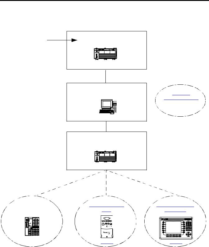
Where to Start
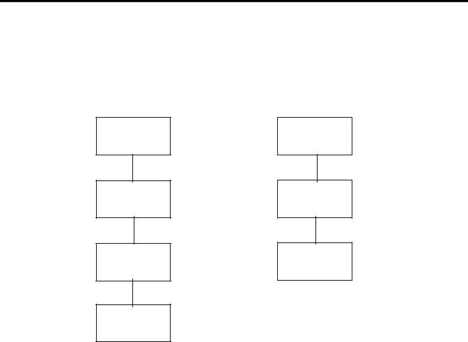
For general information about your packaged controller, start with the User Manual on page 151.
To begin using your packaged |
Chapter 1 |
controller, start here. |
Assemble the CompactLogix |
|
Hardware |
|
CompactLogix L23E |
|
page 23 |
|
Optional Network |
|
(not used to complete examples) |
|
Chapter 2 |
|
Prepare the Computer, Network, and |
|
Controller |
|
DeviceNet Network |
|
page 125 |
|
page 29 |
|
Chapter 3 |
|
Create a Project Using |
|
RSLogix 5000 Software |
|
CompactLogix L23E |
|
page 53 |
Optional |
|
Depending on your system. |
|
Chapter 4 |
|
Add POINT I/O |
|
Modules to the Project |
|
page 73 |
|
Publication IASIMP-QS010B-EN-P - October 2009 |
5 |
Where to Start
Configurations for Quick Start
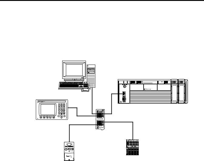
This quick start demonstrates the use of this hardware and network configuration.
Option 1: 1769-L23E Packaged Controller with an EtherNet/IP Network
Workstation
PanelView Plus 600
PV+ 600 |
1769-L23E-QBFC1 or 1769-L23E-QB1B |
|
CompactLogix L23E |
|
I/O |
I/O |
Stratix 6000 Switch
POINT I/O Modules
PowerFlex 40
Component Class
Drive
An Ethernet switch other than the Stratix 6000 switch may be used. For this quick start, the Stratix 6000 switch is recommended.
6 |
Publication IASIMP-QS010B-EN-P - October 2009 |
Where to Start
Option 2: 1769-L23-QBFC1B Packaged Controller with a Serial Network(1)
Workstation
CompactLogix L23
DeviceNet Network
PanelView Plus 600
PV+ 600 |
PowerFlex 40
Component Class Drive
|
|
|
|
|
|
|
|
|
|
|
|
|
|
|
|
|
|
|
|
|
|
|
|
|
|
|
|
|
|
|
|
|
|
|
|
|
|
|
|
|
|
|
|
|
|
|
|
|
|
|
|
|
|
|
|
|
|
|
|
|
|
|
|
|
|
|
|
|
|
|
|
|
|
|
|
|
|
|
|
|
|
|
|
|
|
|
|
|
|
|
|
|
|
|
|
|
|
|
|
|
|
|
|
|
|
|
|
|
|
|
|
|
|
|
|
|
|
|
|
1606 |
|
POINT I/O Modules |
|
|
|||||||||||||||
Power Supply |
|
|
|
|
|
|
|
|
|
|
|
|
|
|
|
|
|||
This option shows an example DeviceNet network that could be configured by using the chapter, Optional - Configuration of the DeviceNet Network (on page 125). While that chapter provides a brief description of how to use a DeviceNet network with a 1769-L23 packaged controller, full details for using a DeviceNet network with any Logix5000 controller are contained in the DeviceNet Modules in Logix5000 Control Systems User Manual, publication DNET-UM004.
Once you have selected your configuration, use the Parts List on page 18 to determine what hardware you need.
If you already have your hardware, proceed to Chapter 1, Assemble the CompactLogix Hardware, on page 23.
(1)
Publication IASIMP-QS010B-EN-P - October 2009 |
7 |

Where to Start
Notes:
8 |
Publication IASIMP-QS010B-EN-P - October 2009 |

Table of Contents
|
Quick Start |
|
Preface |
About This Quick Start . . . . . . . . . . . . . . . . . . . . . . . . . . . . . . . . . . . . . |
15 |
|
Required Software . . . . . . . . . . . . . . . . . . . . . . . . . . . . . . . . . . . . . . . . . |
16 |
|
CompactLogix Packaged Controller Software Requirements . . . . |
16 |
|
POINT I/O Modules and PowerFlex 40 Drive Software |
|
|
Requirements . . . . . . . . . . . . . . . . . . . . . . . . . . . . . . . . . . . . . . . . . . |
16 |
|
PanelView Plus Terminal Software Requirements . . . . . . . . . . . . . |
16 |
|
DeviceNet Network Software Requirements. . . . . . . . . . . . . . . . . |
17 |
|
Parts List . . . . . . . . . . . . . . . . . . . . . . . . . . . . . . . . . . . . . . . . . . . . . . . . . |
18 |
|
Conventions . . . . . . . . . . . . . . . . . . . . . . . . . . . . . . . . . . . . . . . . . . . . . . |
20 |
|
Additional Resources . . . . . . . . . . . . . . . . . . . . . . . . . . . . . . . . . . . . . . . |
21 |
Assemble the CompactLogix
Hardware
Chapter 1
Before You Begin. . . . . . . . . . . . . . . . . . . . . . . . . . . . . . . . . . . . . . . . . . 23 What You Need . . . . . . . . . . . . . . . . . . . . . . . . . . . . . . . . . . . . . . . . . . . 23 Follow These Steps . . . . . . . . . . . . . . . . . . . . . . . . . . . . . . . . . . . . . . . . 24 Connect the Battery to the Packaged Controller . . . . . . . . . . . . . . . . . 25 Record the Ethernet Address (MAC) . . . . . . . . . . . . . . . . . . . . . . . . . . 25 Make Network Connections . . . . . . . . . . . . . . . . . . . . . . . . . . . . . . . . . 26 Wire Power . . . . . . . . . . . . . . . . . . . . . . . . . . . . . . . . . . . . . . . . . . . . . . . 27 Additional Resources . . . . . . . . . . . . . . . . . . . . . . . . . . . . . . . . . . . . . . . 28
Prepare the Computer, Network,
and Controller
Chapter 2
Before You Begin. . . . . . . . . . . . . . . . . . . . . . . . . . . . . . . . . . . . . . . . . . 29 What You Need . . . . . . . . . . . . . . . . . . . . . . . . . . . . . . . . . . . . . . . . . . . 29 Follow These Steps . . . . . . . . . . . . . . . . . . . . . . . . . . . . . . . . . . . . . . . . 30 Terminology . . . . . . . . . . . . . . . . . . . . . . . . . . . . . . . . . . . . . . . . . . . . . . 31 Make Network Connections . . . . . . . . . . . . . . . . . . . . . . . . . . . . . . . . . 31 Install RSLogix 5000 Programming Software. . . . . . . . . . . . . . . . . . . . 33 Configure a Serial Driver . . . . . . . . . . . . . . . . . . . . . . . . . . . . . . . . . . . . 38 Set the IP Address for the Computer . . . . . . . . . . . . . . . . . . . . . . . . . . 40 Assign an IP Address to the Packaged Controller . . . . . . . . . . . . . . . . 42 Configure the EtherNet/IP Driver in RSLinx Software . . . . . . . . . . . 44 Browse the EtherNet/IP Network in RSLinx Software . . . . . . . . . . . 45 Load Firmware . . . . . . . . . . . . . . . . . . . . . . . . . . . . . . . . . . . . . . . . . . . . 46 Install Additional Software . . . . . . . . . . . . . . . . . . . . . . . . . . . . . . . . . . 50 Additional Resources . . . . . . . . . . . . . . . . . . . . . . . . . . . . . . . . . . . . . . . 51
|
Chapter 3 |
|
Create a Project Using |
Before You Begin. . . . . . . . . . . . . . . . . . . . . . . . . . . . . . . . . . . . . . . . . . |
53 |
RSLogix 5000 Software |
What You Need . . . . . . . . . . . . . . . . . . . . . . . . . . . . . . . . . . . . . . . . . . . |
53 |
|
Follow These Steps . . . . . . . . . . . . . . . . . . . . . . . . . . . . . . . . . . . . . . . . |
54 |
|
Create a Project . . . . . . . . . . . . . . . . . . . . . . . . . . . . . . . . . . . . . . . . . . . |
55 |
Publication IASIMP-QS010B-EN-P - October 2009 |
9 |

|
Configure the Packaged Controller . . . . . . . . . . . . . . . . . . . . . . . . . . . . |
57 |
|
Configure Embedded I/O. . . . . . . . . . . . . . . . . . . . . . . . . . . . . . . . . . . |
58 |
|
Add Ladder Logic to Test the Embedded Outputs . . . . . . . . . . . . . . . |
59 |
|
Set the Communication Path and Download to the Controller . . . . . 62 |
|
|
Additional Resources . . . . . . . . . . . . . . . . . . . . . . . . . . . . . . . . . . . . . . . |
64 |
|
Chapter 4 |
|
Add POINT I/O Modules |
Before You Begin. . . . . . . . . . . . . . . . . . . . . . . . . . . . . . . . . . . . . . . . . . |
65 |
|
What You Need . . . . . . . . . . . . . . . . . . . . . . . . . . . . . . . . . . . . . . . . . . . |
65 |
|
Follow These Steps . . . . . . . . . . . . . . . . . . . . . . . . . . . . . . . . . . . . . . . . |
66 |
|
Mount and Connect the Network Adapter. . . . . . . . . . . . . . . . . . . . . . |
67 |
|
Mount the POINT I/O Modules . . . . . . . . . . . . . . . . . . . . . . . . . . . . . |
68 |
|
Mount and Wire the POINT I/O Power Supply. . . . . . . . . . . . . . . . . |
69 |
|
Wire the Adapter and I/O Modules to the Power Supply. . . . . . . . . . |
70 |
|
Assign an IP Address to the POINT I/O Adapter . . . . . . . . . . . . . . . |
71 |
|
Add POINT I/O Modules to the Project . . . . . . . . . . . . . . . . . . . . . . |
73 |
|
Add Ladder Logic . . . . . . . . . . . . . . . . . . . . . . . . . . . . . . . . . . . . . . . . . |
76 |
|
Download the Project . . . . . . . . . . . . . . . . . . . . . . . . . . . . . . . . . . . . . . |
78 |
|
Set the POINT I/O Chassis Size . . . . . . . . . . . . . . . . . . . . . . . . . . . . . |
79 |
|
Test the POINT I/O Light . . . . . . . . . . . . . . . . . . . . . . . . . . . . . . . . . . |
80 |
|
Additional Resources . . . . . . . . . . . . . . . . . . . . . . . . . . . . . . . . . . . . . . . |
81 |
Add a PowerFlex 40 Drive
Add a PanelView Plus 600
Terminal
Chapter 5
Before You Begin. . . . . . . . . . . . . . . . . . . . . . . . . . . . . . . . . . . . . . . . . . 83 What You Need . . . . . . . . . . . . . . . . . . . . . . . . . . . . . . . . . . . . . . . . . . . 83 Follow These Steps . . . . . . . . . . . . . . . . . . . . . . . . . . . . . . . . . . . . . . . . 84 Mount the PowerFlex 40 Drive. . . . . . . . . . . . . . . . . . . . . . . . . . . . . . . 85 Wire Power . . . . . . . . . . . . . . . . . . . . . . . . . . . . . . . . . . . . . . . . . . . . . . . 85 Connect the Communication Adapter . . . . . . . . . . . . . . . . . . . . . . . . . 86 Assign an IP Address to the PowerFlex 40 Drive . . . . . . . . . . . . . . . . 88 Add the Drive to the Project . . . . . . . . . . . . . . . . . . . . . . . . . . . . . . . . . 90 Download the Project . . . . . . . . . . . . . . . . . . . . . . . . . . . . . . . . . . . . . . 92 Edit PowerFlex 40 Parameter Values . . . . . . . . . . . . . . . . . . . . . . . . . . 93
Reference for Editing Parameters . . . . . . . . . . . . . . . . . . . . . . . . . 93 Test the PowerFlex 40 Tags . . . . . . . . . . . . . . . . . . . . . . . . . . . . . . . . . 95 Additional Resources . . . . . . . . . . . . . . . . . . . . . . . . . . . . . . . . . . . . . . . 96
Chapter 6
Before You Begin. . . . . . . . . . . . . . . . . . . . . . . . . . . . . . . . . . . . . . . . . . 97 What You Need . . . . . . . . . . . . . . . . . . . . . . . . . . . . . . . . . . . . . . . . . . . 97 Follow These Steps . . . . . . . . . . . . . . . . . . . . . . . . . . . . . . . . . . . . . . . . 98 Mount the PanelView Plus Terminal . . . . . . . . . . . . . . . . . . . . . . . . . . 99 Wire the PanelView Plus Terminal for Power . . . . . . . . . . . . . . . . . . . 99 Make Network Connections . . . . . . . . . . . . . . . . . . . . . . . . . . . . . . . . 100 Assign an IP Address to the Terminal . . . . . . . . . . . . . . . . . . . . . . . . 101
10 |
Publication IASIMP-QS010B-EN-P - October 2009 |
Optional - Configuration of the
DeviceNet Network
Create a New Application . . . . . . . . . . . . . . . . . . . . . . . . . . . . . . . . . . 102 Create an RSLinx Enterprise Configuration in FactoryTalk View ME Software . . . . . . . . . . . . . . . . . . . . . . . . . . . . . . . . . . . . . . . . . . . . . . . . 103 Create Device Shortcuts to the Controller . . . . . . . . . . . . . . . . . . . . . 105 Create the OB16_Light Indicator . . . . . . . . . . . . . . . . . . . . . . . . . . . . 110 Create a Push Button . . . . . . . . . . . . . . . . . . . . . . . . . . . . . . . . . . . . . . 113 Test the Indicator and Push Button . . . . . . . . . . . . . . . . . . . . . . . . . . 115 Add a Goto Configuration Mode Button . . . . . . . . . . . . . . . . . . . . . . 117 Assign Keys . . . . . . . . . . . . . . . . . . . . . . . . . . . . . . . . . . . . . . . . . . . . . 118 Assign an Initial Screen . . . . . . . . . . . . . . . . . . . . . . . . . . . . . . . . . . . . 120 Transfer to the PanelView Plus Terminal . . . . . . . . . . . . . . . . . . . . . . 121 Test the Application on the PanelView Plus Terminal . . . . . . . . . . . 123 Additional Resources . . . . . . . . . . . . . . . . . . . . . . . . . . . . . . . . . . . . . . 124
Chapter 7
Before You Begin. . . . . . . . . . . . . . . . . . . . . . . . . . . . . . . . . . . . . . . . . 125 What You Need . . . . . . . . . . . . . . . . . . . . . . . . . . . . . . . . . . . . . . . . . . 125 Follow These Steps . . . . . . . . . . . . . . . . . . . . . . . . . . . . . . . . . . . . . . . 126 Attach the 1769-SDN Module to the Packaged Controller . . . . . . . . 127 Connect the 1769-SDN Module to the Network . . . . . . . . . . . . . . . . 128 Connect and Apply Power to the DeviceNet Network . . . . . . . . . . . 129 Set the 1769-SDN Module’s Node Address . . . . . . . . . . . . . . . . . . . . 130 Create a DeviceNet Scanlist. . . . . . . . . . . . . . . . . . . . . . . . . . . . . . . . . 132 Create a DeviceNet Configuration File. . . . . . . . . . . . . . . . . . . . . . . . 135 Add the 1769-SDN Module to the RSLogix 5000 Project. . . . . . . . . 138 Create DeviceNet Tags . . . . . . . . . . . . . . . . . . . . . . . . . . . . . . . . . . . . 140 Additional Resources . . . . . . . . . . . . . . . . . . . . . . . . . . . . . . . . . . . . . . 142
Publication IASIMP-QS010B-EN-P - October 2009 |
11 |

|
User Manual |
|
Preface |
About This User Manual . . . . . . . . . . . . . . . . . . . . . . . . . . . . . . . . . . . |
151 |
|
Additional Resources . . . . . . . . . . . . . . . . . . . . . . . . . . . . . . . . . . . |
151 |
|
Chapter 1 |
|
Overview of the CompactLogix |
Features of the Packaged Controllers . . . . . . . . . . . . . . . . . . . . . . . . . |
153 |
Packaged Controllers |
1769-L23E-QB1B Packaged Controller . . . . . . . . . . . . . . . . . . . . . . . |
154 |
|
1769-L23E-QBFC1B Packaged Controller . . . . . . . . . . . . . . . . . . . . |
154 |
|
1769-L23-QBFC1B Packaged Controller . . . . . . . . . . . . . . . . . . . . . . |
155 |
|
Chapter 2 |
|
Network Communication |
EtherNet/IP Network Communication . . . . . . . . . . . . . . . . . . . . . . . |
158 |
|
Software for an EtherNet/IP Network . . . . . . . . . . . . . . . . . . . . |
158 |
|
EtherNet/IP Network Features . . . . . . . . . . . . . . . . . . . . . . . . . . |
159 |
|
EtherNet/IP Network Connections. . . . . . . . . . . . . . . . . . . . . . . |
159 |
|
Configure the 1769-L23E Ethernet Interface . . . . . . . . . . . . . . . |
161 |
|
Additional Resources for EtherNet/IP Networks. . . . . . . . . . . . |
163 |
|
DeviceNet Network Communication . . . . . . . . . . . . . . . . . . . . . . . . . |
164 |
|
CompactLogix DeviceNet Scanner. . . . . . . . . . . . . . . . . . . . . . . . |
164 |
|
Software for a DeviceNet Network . . . . . . . . . . . . . . . . . . . . . . . |
164 |
|
DeviceNet Network Features . . . . . . . . . . . . . . . . . . . . . . . . . . . . |
165 |
|
Using DeviceNet Modules with the CompactLogix Controller . 165 |
|
|
Additional Resources for DeviceNet Networks. . . . . . . . . . . . . . |
165 |
|
Serial Communication . . . . . . . . . . . . . . . . . . . . . . . . . . . . . . . . . . . . . |
166 |
|
Determine Need for Isolator and Cable for Connection. . . . . . . |
167 |
|
Communicate with DF1 Devices . . . . . . . . . . . . . . . . . . . . . . . . . |
169 |
|
Communicate with ASCII Devices. . . . . . . . . . . . . . . . . . . . . . . . |
172 |
|
ASCII Instructions. . . . . . . . . . . . . . . . . . . . . . . . . . . . . . . . . . . . . |
174 |
|
Modbus Support . . . . . . . . . . . . . . . . . . . . . . . . . . . . . . . . . . . . . . |
176 |
|
Broadcast Messages Over a Serial Port. . . . . . . . . . . . . . . . . . . . . |
176 |
|
DH-485 Network Communication . . . . . . . . . . . . . . . . . . . . . . . . . . . |
184 |
|
Additional Resources for DH-485 Communication . . . . . . . . . . |
188 |
|
Additional Resources for Serial Communication . . . . . . . . . . . . . |
189 |
|
Chapter 3 |
|
Embedded I/O |
Embedded I/O . . . . . . . . . . . . . . . . . . . . . . . . . . . . . . . . . . . . . . . . . . |
191 |
|
Embedded I/O Tags . . . . . . . . . . . . . . . . . . . . . . . . . . . . . . . . . . . . . . |
192 |
|
Digital Inputs . . . . . . . . . . . . . . . . . . . . . . . . . . . . . . . . . . . . . . . . . . . . |
194 |
|
DC Input Wiring . . . . . . . . . . . . . . . . . . . . . . . . . . . . . . . . . . . . . . |
194 |
|
DC Input Filtering . . . . . . . . . . . . . . . . . . . . . . . . . . . . . . . . . . . . . |
195 |
|
Configure the DC Inputs. . . . . . . . . . . . . . . . . . . . . . . . . . . . . . . . |
195 |
|
DC Input Tags . . . . . . . . . . . . . . . . . . . . . . . . . . . . . . . . . . . . . . . . |
197 |
|
Digital Outputs. . . . . . . . . . . . . . . . . . . . . . . . . . . . . . . . . . . . . . . . . . . |
198 |
|
DC Output Wiring. . . . . . . . . . . . . . . . . . . . . . . . . . . . . . . . . . . . . |
198 |
12 |
Publication IASIMP-QS010B-EN-P - October 2009 |

|
Configure the DC Outputs . . . . . . . . . . . . . . . . . . . . . . . . . . . . . . |
199 |
|
DC Output Tags . . . . . . . . . . . . . . . . . . . . . . . . . . . . . . . . . . . . . . |
199 |
|
Analog I/O. . . . . . . . . . . . . . . . . . . . . . . . . . . . . . . . . . . . . . . . . . . . . . |
200 |
|
Analog I/O Wiring Diagrams . . . . . . . . . . . . . . . . . . . . . . . . . . . . |
200 |
|
Configure the Analog I/O . . . . . . . . . . . . . . . . . . . . . . . . . . . . . . |
203 |
|
Analog I/O Tags . . . . . . . . . . . . . . . . . . . . . . . . . . . . . . . . . . . . . . |
205 |
|
High-speed Counters . . . . . . . . . . . . . . . . . . . . . . . . . . . . . . . . . . . . . . |
207 |
|
High-speed Counters Wiring Diagrams . . . . . . . . . . . . . . . . . . . . |
207 |
|
Configure the High-speed Counters . . . . . . . . . . . . . . . . . . . . . . . |
212 |
|
High-speed Counter Tags . . . . . . . . . . . . . . . . . . . . . . . . . . . . . . . |
216 |
|
Range Control of the HSC . . . . . . . . . . . . . . . . . . . . . . . . . . . . . . |
225 |
|
Other Configuration Parameters . . . . . . . . . . . . . . . . . . . . . . . . . . . . . |
226 |
|
Additional Resources . . . . . . . . . . . . . . . . . . . . . . . . . . . . . . . . . . . . . . |
227 |
|
Chapter 4 |
|
Add Additional Local I/O |
Expansion Modules . . . . . . . . . . . . . . . . . . . . . . . . . . . . . . . . . . . . . . . |
229 |
|
Determine Expansion Module Limits. . . . . . . . . . . . . . . . . . . . . . . . . |
230 |
|
Add Expansion I/O Modules . . . . . . . . . . . . . . . . . . . . . . . . . . . . . . . |
231 |
|
Expansion I/O RPI. . . . . . . . . . . . . . . . . . . . . . . . . . . . . . . . . . . . |
231 |
|
Additional Resources . . . . . . . . . . . . . . . . . . . . . . . . . . . . . . . . . . . . . . |
232 |
|
Chapter 5 |
|
Program the Packaged Controller |
Program the Controller . . . . . . . . . . . . . . . . . . . . . . . . . . . . . . . . . . . . |
234 |
|
Tasks. . . . . . . . . . . . . . . . . . . . . . . . . . . . . . . . . . . . . . . . . . . . . . . . |
234 |
|
Programs and Equipment Phases . . . . . . . . . . . . . . . . . . . . . . . . . |
234 |
|
Trends. . . . . . . . . . . . . . . . . . . . . . . . . . . . . . . . . . . . . . . . . . . . . . . |
235 |
|
Monitoring Controller Status . . . . . . . . . . . . . . . . . . . . . . . . . . . . |
235 |
|
Additional Resources . . . . . . . . . . . . . . . . . . . . . . . . . . . . . . . . . . . . . . |
236 |
|
Chapter 6 |
|
Battery Maintenance |
Battery for Use with Packaged Controllers. . . . . . . . . . . . . . . . . . . . . |
237 |
|
Check Battery Power Level . . . . . . . . . . . . . . . . . . . . . . . . . . . . . . . . . |
237 |
|
Estimate 1769-BA Battery Life . . . . . . . . . . . . . . . . . . . . . . . . . . . . . . |
238 |
|
Store Batteries. . . . . . . . . . . . . . . . . . . . . . . . . . . . . . . . . . . . . . . . . . . . |
238 |
|
Additional Resources . . . . . . . . . . . . . . . . . . . . . . . . . . . . . . . . . . . . . . |
238 |
Network Worksheet |
EtherNet/IP Network . . . . . . . . . . . . . . . . . . . . . . . . . . . . . . . . . . . . . |
239 |
|
DeviceNet Network. . . . . . . . . . . . . . . . . . . . . . . . . . . . . . . . . . . . . . . |
239 |
|
1769-SDN Module Information . . . . . . . . . . . . . . . . . . . . . . . . . . . . . |
239 |
|
RSNetWorx for DeviceNet Configuration File Information. . . . . . . |
239 |
Index |
|
|
Publication IASIMP-QS010B-EN-P - October 2009 |
13 |

Notes:
14 |
Publication IASIMP-QS010B-EN-P - October 2009 |

Preface
About This Quick Start
This quick start provides examples and procedures for the use of a CompactLogix packaged controller system. This publication also includes RSLogix 5000 programming software version 18 updates.
The procedures cover many of the most common user tasks, such as:
•connecting the controller to multiple devices (local and distributed I/O, a drive, and a PanelView Plus terminal).
•connecting and configuring networks (EtherNet/IP, DeviceNet, and serial) for use with CompactLogix systems.
•creating and monitoring controller programs.
The examples are designed to get devices installed and communicating with each other in the simplest way possible. The programming examples are not complex, and offer easy solutions to verify that devices are functioning and communicating properly.
The beginning of each chapter contains the following information. Read these sections carefully before beginning work in each chapter:
•Before You Begin - This section lists the steps that must be completed and decisions that must be made before starting that chapter. The chapters in this quick start do not have to be completed in the order in which they appear, but this section defines the minimum amount of preparation required before completing the current chapter.
•What You Need - This section lists the tools that are required to complete the steps in the current chapter. This includes, but is not limited to, hardware and software.
•Follow These Steps - This illustrates the steps in the current chapter and identifies which steps are required to complete the examples for specific networks or configurations.
Also, additional resources, such as websites, technical notes, and other Rockwell Automation publications are listed in the Additional Resources tables at the end of each chapter.
Publication IASIMP-QS010B-EN-P - October 2009 |
15 |

5
Required Software
Your software requirements depend upon the CompactLogix system components you are using. Use the sections below to determine the software required for your system components.
CompactLogix Packaged Controller Software Requirements
To complete any of the examples in this quick start, you need one of these editions of RSLogix 5000 programming software, version 17 or later:
•Lite
•Mini
•Full
•Standard
•Professional
You install and use these utilities included with the RSLogix 5000 programming software to complete the examples in this quick start:
•BootP-DHCP server
•ControlFlash
•RSLinx Classic, version 2.54 or later
Verify that these utilities are included with your RSLogix 5000 software package.
POINT I/O Modules and PowerFlex 40 Drive Software
Requirements
If you are using POINT I/O modules or a PowerFlex 40 drive to complete examples in this quick start, only the software listed for the CompactLogix packaged controllers is required.
PanelView Plus Terminal Software Requirements
If you plan to complete the PanelView Plus examples within this quick start, FactoryTalkView Machine Edition software is required in addition to the software required for the use of the packaged controller.
16 |
Publication IASIMP-QS010B-EN-P - October 2009 |

5
DeviceNet Network Software Requirements
If you plan to use a DeviceNet network with your packaged controller, this software is required:
•RSNetWorx for DeviceNet
•DeviceNet Tag Generator (included with RSLogix 5000 programming software)
Publication IASIMP-QS010B-EN-P - October 2009 |
17 |

5
Parts List
This table lists the hardware used in this quick start. The hardware you need depends on the options and examples you choose to complete. Specific hardware requirements are listed at the beginning of each chapter.
Hardware Used in This Quick Start
|
Quantity |
Cat. No. |
Description |
|
|
|
|
General Configuration |
|
||
|
|
|
|
|
1 |
1769-L23E-QB1B, |
CompactLogix Packaged Controller |
|
|
1769-L23E-QBFC1B, or |
|
|
|
1769-L23-QBFC1B |
|
|
|
|
|
|
1 |
1769-ECR |
Compact I/O Right End Cap/Terminator (included with packaged controller) |
|
|
|
|
|
1 |
1734-IB4(1) |
POINT I/O 4 Sink Input Module |
|
1 |
1734-OB4E(2) |
POINT I/O 4 Protected Output Module |
|
1 |
1734-OE2C(1) |
POINT I/O 2 Current Output Analog Module |
|
1-3 |
1734-TB(3) |
Wiring Base w/ Removable IEC Screw Terminals |
|
1 |
1794-PS13 |
FLEX I/O 85…264V AC to 24V DC 1.3 A Power Supply |
|
|
|
|
|
1 |
22B-V2P3N104 |
PowerFlex 40 Drive |
|
|
|
|
|
1 |
22B-CCB |
PowerFlex 40 Communication Adapter Cover |
|
|
|
|
|
1 |
2711P-T6C20A |
PanelView Plus 6-inch Color Keypad Terminal with EtherNet/IP and RS-232 Networks |
|
|
|
|
|
1 |
1794-PS3 or |
Flex I/O Power Supply or Other General-use Power Supply to supply 70 W DC power to |
|
|
2711P-RSACDIN |
PanelView Plus (if DC power is required for your terminal) |
|
|
|
|
|
2 |
1756-CP3 |
RS-232 Cable |
|
|
|
|
|
1 |
2706-NC13 |
PanelView Plus Serial Cable |
|
|
|
|
|
2…3 |
N/A |
DIN Rail (steel not aluminum) |
|
|
|
|
|
1 |
1606-XLS80E |
DC Power Supply |
|
|
|
|
|
|
|
|
EtherNet/IP Configuration |
|
||
|
|
|
|
|
1 |
1734-AENT |
POINT I/O EtherNet/IP Adapter |
|
|
|
|
|
1 |
22-COMM-E |
EtherNet/IP Adapter for Use With the PowerFlex 40 Drive |
|
|
|
|
|
1 |
1783-EMS08T |
Stratix 6000 Ethernet Switch (recommended), Stratix 2000 Ethernet Switch (for |
|
|
|
applications without remote I/O), or other Ethernet Switch |
|
|
|
|
|
6 |
1585J-M8 |
Industrial-grade Ethernet Cables(5) or Other Standard Ethernet Cables |
|
|
|
|
Serial Configuration |
|
||
|
|
|
|
|
1 |
1756-CP3 |
RS-232 cable |
|
|
|
|
|
1 |
2706-NC13 |
Point-to-point RS-232 Cable (required with 1769-L23-QBFC1B packaged controllers, |
|
|
|
optional with 1769-L23E packaged controllers) |
|
|
|
|
18 |
Publication IASIMP-QS010B-EN-P - October 2009 |

5
Hardware Used in This Quick Start
|
Quantity |
Cat. No. |
Description |
|
|
|
|
DeviceNet Configuration |
|
||
|
|
|
|
|
1 |
1769-SDN |
Compact I/O DeviceNet Scanner |
|
|
|
|
|
1 |
1734-ADNX(4) |
POINT I/O DeviceNet Adapter |
|
1 |
22-COMM-D |
DeviceNet Adapter for Use with the PowerFlex 40 Drive |
|
|
|
|
|
1 |
1606-XLDNET8 |
DeviceNet Power Supply |
|
|
|
|
|
N/A |
1485C-P1E75 |
KwikLink Flat Cable |
|
|
|
|
|
2 |
1485A-T1E4 |
KwikLink Terminator/Resistor |
|
|
|
|
|
4 |
1485P-P1E4-R5 |
KwikLink Sealed Micro Connector |
|
|
|
|
|
4 |
1485K-P1F5-C |
KwikLink Right-angle Male to Cable |
|
|
|
|
|
1 |
1485T-P1E4-B1 |
KwikLink Power Tap Module |
|
|
|
|
|
|
|
|
(1)Use POINT I/O modules at series C or later to complete examples in this quick start.
(2)The 1734-OB4E module is the only POINT I/O module used in this quick start. The other modules are added only as examples and are not required.
(3)The number of wiring bases you need depends upon the number of POINT I/O modules you use in your system.
(4)The examples in this quick start use the 1734-ADNX POINT I/O adapter. However, you may choose to use the 1734-ADN adapter instead.
(5)For more information about industrial grade cables, see the Ethernet Connectivity product profile, publication 1585-PP001.
Publication IASIMP-QS010B-EN-P - October 2009 |
19 |

5
Conventions
This manual uses the following conventions.
Convention |
Meaning |
Example |
|
|
|
bold |
Bold text denotes menus, menu items, buttons, or options. |
Click OK. |
|
|
|
Check/uncheck |
Click to activate/deactivate a checkbox. |
Check the Open Module Properties checkbox. |
|
|
|
Click |
Click left mouse button once. (Assumes cursor is positioned on |
Click Browse. |
|
object or selection.) |
|
|
|
|
Courier |
Type or enter text exactly as shown. |
Type cmd. |
font |
|
|
Double-click |
Click left mouse button twice in quick succession. (Assumes |
Double-click the H1 icon. |
|
cursor is positioned on object or selection.) |
|
|
|
|
Expand |
Click the + to the left of a given item /folder to show its |
In the H1-1 window, expand the FFLD. |
|
contents. |
|
|
|
|
Right-click |
Click right mouse button once. (Assumes cursor is positioned on |
Right-click the Fieldbus Networks icon. |
|
object or selection.) |
|
|
|
|
Select |
Click to highlight a menu item or list choice. |
Select Properties from the pull-down menu. |
|
|
|
> |
Shows nested menu selections as menu name followed by menu |
Click File > Page Setup > Options. |
|
selection. |
|
|
|
|
20 |
Publication IASIMP-QS010B-EN-P - October 2009 |
5
Additional Resources
Resource |
Description |
|
|
1769 CompactLogix Controllers Selection |
Provides information and specifications for consideration when selecting CompactLogix |
Guide, publication 1769-SG001 |
controllers and software. |
|
|
1769 Compact I/O Selection Guide, publication |
Provides information and specifications for consideration when selecting I/O modules |
1769-SG002 |
for use with the CompactLogix system. It includes Compact I/O, POINT I/O, and FLEX I/O |
|
modules. |
|
|
NetLinx Selection Guide, publication |
Provides information and specifications for consideration when selecting a network to |
NETS-SG001 |
use and which hardware and cables you need. |
|
|
EtherNet/IP Media Planning and Installation |
Provides information about how to select and install your EtherNet/IP network physical |
Manual, publication ENET-IN001 |
media. |
|
|
Ethernet Connectivity Product Profile, |
Provides information specific to the industrial-grade Ethernet Connectivity products, |
publication 1585-PP001 |
including RJ45 cables, offered by Rockwell Automation. |
|
|
Publications are available for viewing or electronic download at http://literature.rockwellautomation.com.
Publication IASIMP-QS010B-EN-P - October 2009 |
21 |

5
Notes:
22 |
Publication IASIMP-QS010B-EN-P - October 2009 |

Chapter 1
Assemble the CompactLogix Hardware
In this chapter, you install your CompactLogix hardware packaged controller.
Before You Begin
Determine which of these networks and appropriate hardware to use:
•For the EtherNet/IP network (option 1), use either the 1769-L23E-QB1B or 1769-L23E-QBFC1B controller.
•For a serial connection (option 2), use the 1769-L23-QBFC1B controller.
What You Need
•CompactLogix packaged controller: 1769-L23E-QB1B, 1769-L23E-QBFC1B, or 1769-L23-QBFC1B.
•CompactLogix controller battery: 1769-BA (included with your controller).
•Power supply: This quick start uses the 1606-XLS80E supply, but any DC power supply that meets the requirements for the 1769-L23 controllers may be used.
•Compact I/O end cap: 1769-ECR (included with your controller).
•Compact I/O DeviceNet scanner module: 1769-SDN (only if you are using a DeviceNet network).
•Network cable: Ethernet (1585J-M8 or similar), serial (1756-CP3).
•Stratix 6000 or other Ethernet switch.
Publication IASIMP-QS010B-EN-P - October 2009 |
23 |
Chapter 1 Assemble the CompactLogix Hardware
Follow These Steps
Complete the steps shown for your controller.
1769-L23E
Connect the Battery
to the Packaged
Controller
page 25
Record the
Ethernet Address
(MAC)
page 25
Make Network
Connections
page 26
Wire Power
page 27
1769-L23
Connect the Battery
to the Packaged
Controller
page 25
Make Network
Connections
page 26
Wire Power
page 27
24 |
Publication IASIMP-QS010B-EN-P - October 2009 |

Assemble the CompactLogix Hardware |
Chapter 1 |
|
|
Connect the Battery to the Packaged Controller
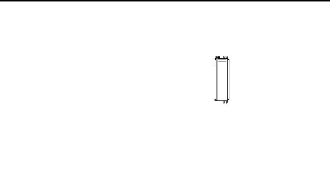
Battery
1. Remove the battery door and connect the battery to the controller.
2. Insert the battery into the slot on the battery door.
3. Close the battery door.
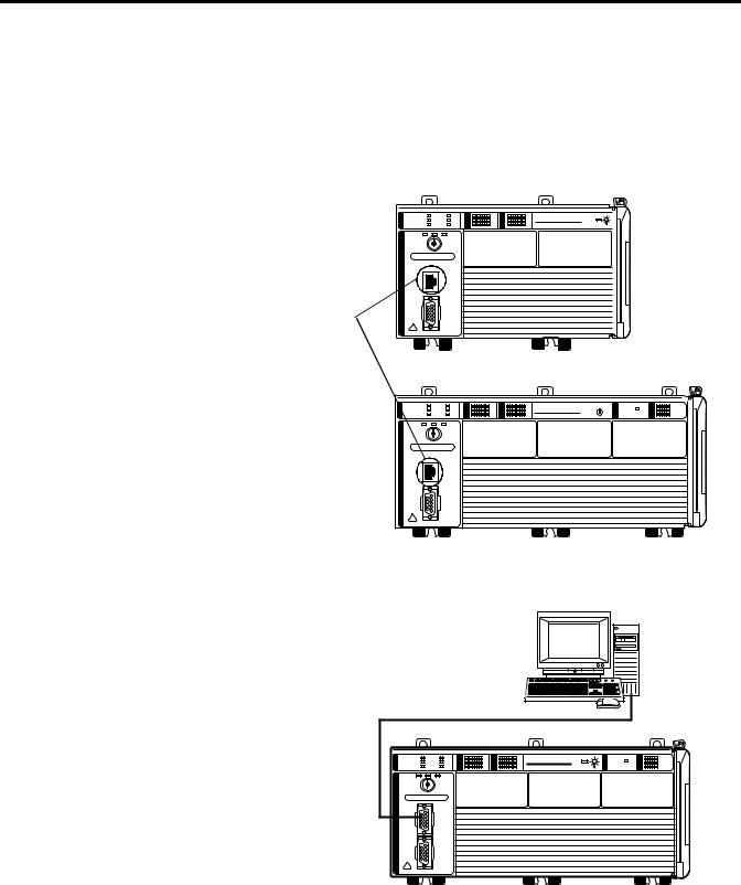
Record the Ethernet Address (MAC)
1769-L23E controllers
The Ethernet address (MAC) is found on a label near the power-supply wiring terminal. This is an example address.
00:00:BC:21:D7:BE Ethernet Address
Record the Ethernet address (MAC) for the CompactLogix controller on the
Network Worksheet at the back of this quick start. This address may be used to set the IP address later.
Publication IASIMP-QS010B-EN-P - October 2009 |
25 |
Chapter 1 Assemble the CompactLogix Hardware
Make Network Connections
1769-L23E packaged controllers, option 1
1.Insert an Ethernet cable with an RJ45 connector.
2.Connect the other end of the cable to the Ethernet switch.
Ethernet Ports
1769-L23 packaged controllers, option 2
1.Connect the 1756-CP3 cable to the channel 0 serial port on the controller.
CompactLogix L23E |
CompactLogix L23E
QBFC-1B |
2.Connect the other end of the cable to a COM port on the computer.
CompactLogix L23 |
1769-L23-QBFC1B
26 |
Publication IASIMP-QS010B-EN-P - October 2009 |
Assemble the CompactLogix Hardware |
Chapter 1 |
|
|
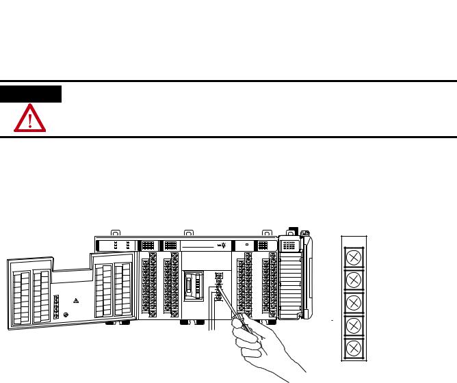
Wire Power
Power supply for all packaged controllers
WARNING
Verify that all incoming power is turned off before wiring power.
1.Insert the +24V DC, DC neutral, and ground wires and tighten the terminal screws.
2.Turn on incoming power.
CompactLogix L23E
QBFC-1B
No Connection
No Connection
+24V DC
DC Neutral
System Power Ground
Publication IASIMP-QS010B-EN-P - October 2009 |
27 |

Chapter 1 Assemble the CompactLogix Hardware
Additional Resources
Resource |
Description |
|
|
Chapter 6 of the user manual, page 237 |
Provides detailed information about the use of the 1769-BA with the packaged |
|
controllers. |
|
|
CompactLogix Packaged Controllers Installation |
Provides details about assembling and mounting the controller and upgrading firmware |
Instructions, publication 1769-IN082 |
as well as controller technical specifications. |
|
|
Publications are available for viewing or electronic download at http://literature.rockwellautomation.com.
28 |
Publication IASIMP-QS010B-EN-P - October 2009 |

Chapter 2
Prepare the Computer, Network, and Controller
In this chapter, you configure network communication on your computer and install the necessary programming and configuration software.
In this chapter, you also assign IP addresses to devices on an EtherNet/IP network. For more information about using the packaged controllers on an EtherNet/IP network, see Chapter 2 of the user manual, titled Network Communication (page 157).
Before You Begin
•Verify that your computer meets the software’s system requirements for your edition of RSLogix 5000 software.
What You Need
•RSLogix 5000 software (see the Preface for version and edition information).
•ControlFlash software (packaged with RSLogix 5000 software).
•RLinx Classic software, version 2.54 or later (packaged with RSLogix 5000 software).
•BOOTP/DHCP server utility (packaged with RSLogix 5000 software).
•The computer needs a Network Interface Card (NIC) and its associated Windows driver installed (the NIC and driver are standard on most computers).
•An Ethernet Address (MAC) for each device. You recorded these addresses in the Network Worksheet on the back cover.
•A planned IP Address for each device. If you are using an isolated network, determine a numbering convention for your IP addresses. Record these addresses on the
Network Worksheet inside the back cover.
Publication IASIMP-QS010B-EN-P - October 2009 |
29 |

Chapter 2 Prepare the Computer, Network, and Controller
Follow These Steps
Complete these steps.
EtherNet/IP
Make Network
Connections
page 31
Install RSLogix 5000 Programming
page 33
Set the IP Address
for the Computer
page 40
Assign an IP
Address to the
Packaged Controller
page 42
Configure the
EtherNet/IP Driver
in RSLinx Software
page 44
Browse the
EtherNet/IP Network
in RSLinx Software
page 45
Optional
Install additional software specific to your system.
page 50
Serial
Make Network
Connections
page 31
Install RSLogix 5000 Programming
page 33
Configure a Serial
Driver
page 38
Optional
Install additional software specific to your system.
page 50
30 |
Publication IASIMP-QS010B-EN-P - October 2009 |
Loading...