

Page 1

Installation Instructions
Display Backlight for PanelView 600 (Series C)
(Cat. No. 2711-NL5 - Series C)
Inside. . .
English Section ......................................................................................................3
Section en français................................................................................................7
Deutscher Abschnitt ............................................................................................11
Sezione in Italiano ...............................................................................................15
Sección en español..............................................................................................19
Seção em português............................................................................................23
Publication 2711-IN040A-MU-P - October 2003
Page 2
2 Display Backlight for PanelView 600 (Series C)
Important User Information
Solid state equipment has operational characteristics differing from those of electromechanical equipment.
Safety Guidelines for the Application, Installation and Maintenance of Solid State Controls (Publication
SGI-1.1 available from your local Rockwell Automation sales office or online at
http://www.ab.com/manuals/gi) describes some important differences between solid state equipment and
hard-wired electromechanical devices. Because of this difference, and also because of the wide variety of
uses for solid state equipment, all persons responsible for applying this equipment must satisfy themselves
that each intended application of this equipment is acceptable.
In no event will Rockwell Automation, Inc. be responsible or liable for indirect or consequential damages
resulting from the use or application of this equipment.
The examples and diagrams in this manual are included solely for illustrative purposes. Because of the many
variables and requirements associated with any particular installation, Rockwell Automation, Inc. cannot
assume responsibility or liability for actual use based on the examples and diagrams.
No patent liability is assumed by Rockwell Automation, Inc. with respect to use of information, circuits,
equipment, or software described in this manual.
Reproduction of the contents of this manual, in whole or in part, without written permission of Rockwell
Automation, Inc. is prohibited.
Throughout this manual we use notes to make you aware of safety considerations.
WARNING
Identifies information about practices or circumstances that can cause an explosion in a
hazardous environment, which may lead to personal injury or death, property damage,
or economic loss.
IMPORTANT
ATTENTION
SHOCK HAZARD
BURN HAZARD
Identifies information that is critical for successful application and understanding of the
product.
Identifies information about practices or circumstances that can lead to personal injury
or death, property damage, or economic loss. Attentions help you:
• identify a hazard
• avoid a hazard
• recognize the consequence
Labels may be located on or inside the drive to alert people that dangerous voltage may
be present.
Labels may be located on or inside the drive to alert people that surfaces may be
dangerous temperatures.
Publication 2711-IN040A-MU-P - October 2003
Page 3
Installation Instructions
Display Backlight for PanelView 600 (Series C)
English Section
This instruction sheet describes how to replace the backlight in the following
PanelView terminal:
Terminal Backlight Catalog Number
PanelView 600 (Series C) 2711-NL5
TIP
This publication excludes PanelView 600 Touch only.
Kit Contents
• Replacement backlight (quantity 2)
• Bezel screws (quantity 6)
• Display mounting plate screws (quantity 4)
The backlight uses Cold Cathode Fluorescent Lamp (CCFL) tubes to illuminate the
display.
ATTENTION
• Disconnect all power from the PanelView terminal before
replacing the backlight. Failure to disconnect power may
result in electrical shock and/or damage to the terminal.
• Do not touch any of the exposed electronic components
to prevent damage from electrostatic discharge (ESD).
• Installer must use proper Anti-ESD equipment.
Publication 2711-IN040A-MU-P - October 2003
Page 4
4 Display Backlight for PanelView 600 (Series C)
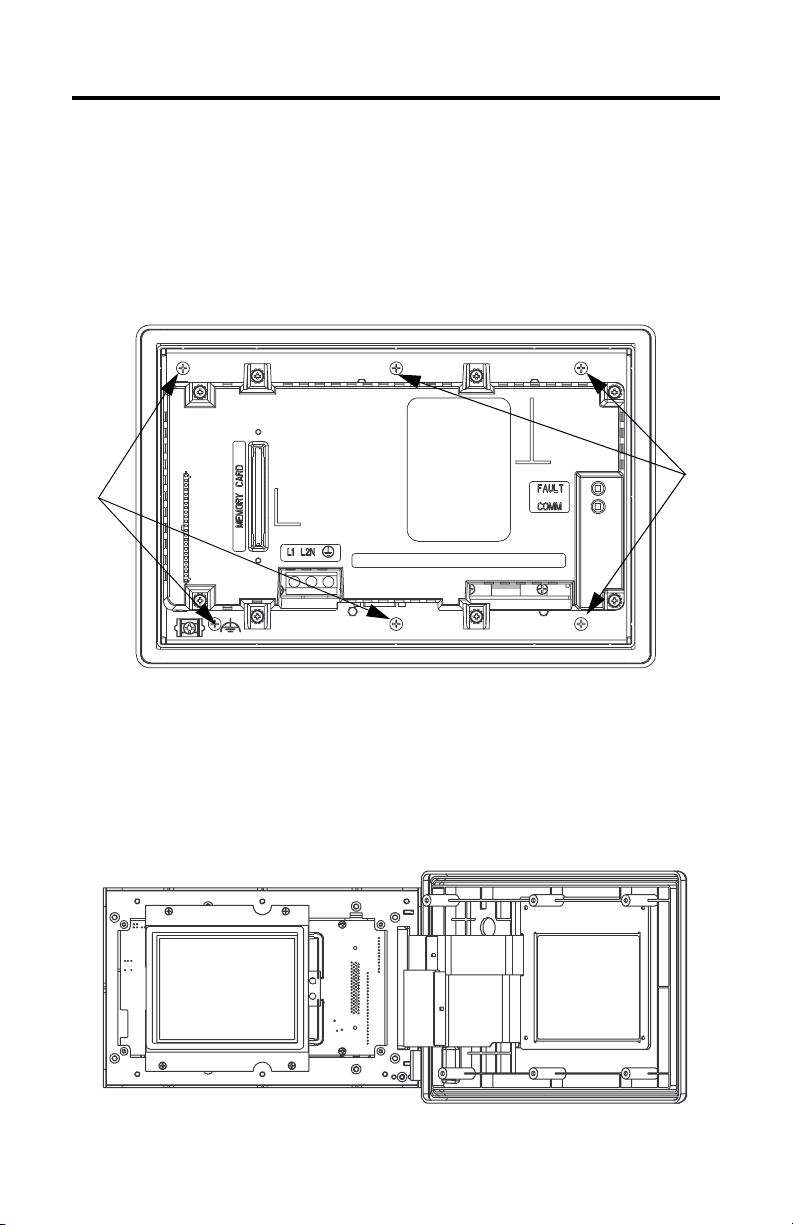
To Remove the Backlight
1. Turn off the power to the PanelView terminal.
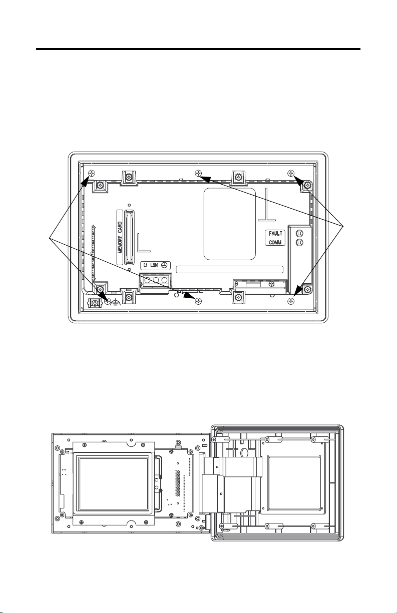
2. Lay terminal on front. Remove six bezel screws from the shroud.
Bezel
Screws
Bezel
Screws
3. Turn terminal over and rest on back cover.
4. Open bezel to the right. Use caution with cables; prop up bezel so cables
are not strained.
Publication 2711-IN040A-MU-P - October 2003
Page 5

Display Backlight for PanelView 600 (Series C) 5
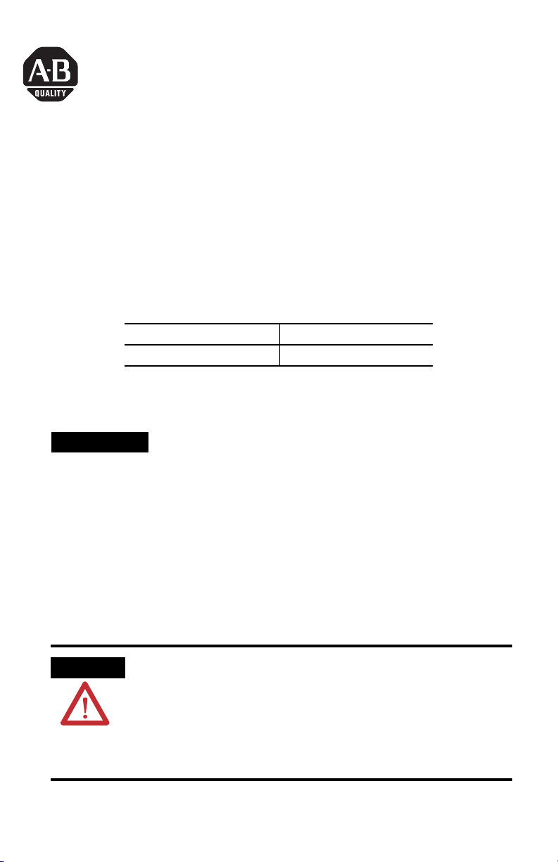
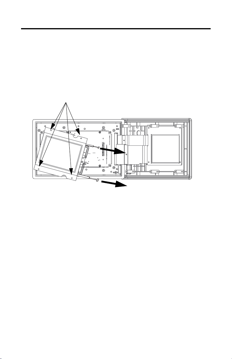
5. Disconnect cables to backlights.
6. Unscrew 4 display mounting plate screws.
7. Turn display to side, remove backlights by pressing tab and gently pulling
straight out on wires.
Display Mounting Screws
8. Properly dispose of old tubes.
Publication 2711-IN040A-MU-P - October 2003
Page 6

6 Display Backlight for PanelView 600 (Series C)
To Install the Backlight
1. Install new backlights. Ensure backlights click into place.
2. Place display mounting plate over standoffs and install four display
mounting plate screws. (Replacement screws are provided.) Torque to 6 to 8
in-lb (0.68 to 0.90 Nm).
3. Plug backlights into appropriate cable, making sure cables click together
firmly.
4. Ensure back of display window is clean and slide bezel into place making
sure to be careful with the bezel connection.
5. Install six bezel screws. (Replacement screws are provided.) Torque to 12 to
14 in-lb (1.35 to 1.58 Nm).
6. Apply power and verify operation of the backlight.
7. If the display does not illuminate, refer to the troubleshooting chart in the
PanelView Standard User Manual, publication 2711-UM014. Recheck all
connections and free pathways for cabling.
Publication 2711-IN040A-MU-P - October 2003
Page 7
Notice d'installation
Rétroéclairage pour PanelView 600 (série C)
Section en français
Cette notice explique comment remplacer le rétroéclairage des terminaux
PanelView suivants :
Terminal Référence du rétroéclairage
PanelView 600 (série C) 2711-NL5
CONSEIL
Cette publication ne porte pas sur les PanelView 600 à
dalle tactile seule.
Contenu du kit
• Rétroéclairage de rechange (quantité 2)
• Vis pour la face avant (quantité 6)
• Vis pour la plaque de fixation de l’écran (quantité 4)
L’écran est éclairé grâce à des lampes fluorescentes à cathode froide (CCFL).
ATTENTION
• Coupez toute alimentation du terminal PanelView avant de
remplacer le rétroéclairage. En cas de non-respect de cette
consigne, vous risquez de vous électrocuter et/ou
d’endommager le terminal.
• Ne touchez pas les composants électroniques exposés pour
éviter de les endommager par une décharge électrostatique.
• L’installateur doit utiliser un équipement antistatique approprié.
Publication 2711-IN040A-MU-P - Octobre 2003
Page 8
8 Rétroéclairage pour PanelView 600 (série C)
Dépose du rétroéclairage
1. Coupez l’alimentation du terminal PanelView.
2. Posez le terminal sur sa face avant. Retirez les six vis qui maintiennent le
boîtier fermé.
Vis
maintenant
la face
avant
Vis
maintenant
la face
avant
3. Retournez le terminal et posez-le sur sa face arrière.
4. Ouvrez la face avant vers la droite. Manipulez les câbles avec précaution ;
soutenez la face avant afin de ne pas exercer de tension sur les câbles.
Publication 2711-IN040A-MU-P - Octobre 2003
Page 9
Rétroéclairage pour PanelView 600 (série C) 9
5. Débranchez les câbles du rétroéclairage.
6. Retirez les 4 vis de la plaque de fixation de l’écran.
7. Tournez l’écran sur le côté, retirez les lampes en appuyant sur la languette et
en tirant doucement sur les fils.
Vis de fixation de l’écran
8. Mettez les lampes usagées au rebut en vous conformant à la réglementation
en vigueur.
Publication 2711-IN040A-MU-P - Octobre 2003
Page 10

10 Rétroéclairage pour PanelView 600 (série C)
Mise en place du rétroéclairage
1. Installez le nouveau rétroéclairage. Veillez à ce que les lampes s’enclenchent
bien.
2. Placez la plaque de fixation de l’écran sur les espaceurs et remettez en place
les quatre vis de la plaque de fixation de l’écran (des vis de rechange sont
fournies). Serrez les vis avec un couple de 0,68 - 0,90
3. Branchez les lampes sur les câbles appropriés, en veillant à ce que ces
derniers s’insèrent bien.
4. Vérifiez que la face antérieure de la fenêtre de l’écran est propre et refermez
la face avant en veillant à sa connexion.
5. Remettez les six vis de la face avant en place (des vis de rechange sont
fournies). Serrez les vis avec un couple de 1,35 - 1,58 Nm.
6. Mettez le terminal sous tension et vérifiez le fonctionnement du
rétroéclairage.
7. Si l’écran ne s’allume pas, consultez le tableau de dépannage dans le manuel
utilisateur des PanelView standard (publication 2711-UM014). Vérifiez de
nouveau toutes les connexions et assurez-vous que rien ne gêne
l’acheminement des câbles.
Nm.
Publication 2711-IN040A-MU-P - Octobre 2003
Page 11

Installationsanleitung
Anzeigenhintergrundbeleuchtung für
PanelView
600 (Serie C)
Deutscher Abschnitt
In dieser Anleitung wird beschrieben, wie die Hintergrundbeleuchtung des
folgenden PanelView-Terminals ausgewechselt wird:
Terminal Best.-Nr. der
Hintergrundbeleuchtung
PanelView 600 (Serie C) 2711-NL5
TIPP
Nur das Terminal PanelView 600 mit Touchscreen wird
von dieser Publikation ausgeschlossen.
Inhalt des Kits
• Ersatzhintergrundbeleuchtung (2 Stück)
• Schrauben für Frontplatte (6 Stück)
• Schrauben für die Montageplatte der Anzeige (4 Stück)
Die Hintergrundbeleuchtung verwendet zur Beleuchtung der Anzeige
Kaltkathoden-Fluoreszenzröhren.
ACHTUNG
• Unterbrechen Sie vor dem Ersetzen der Hintergrundbeleucht-
ung die Stromversorgung zum PanelView-Terminal. Wird die
Stromversorgung nicht unterbrochen, kann dies zu Stromschlägen und/oder zur Beschädigung des Terminals führen.
• Berühren Sie auf keinen Fall die freigelegten elektronischen
Komponenten, um Schäden durch elektrostatische Entladung
zu vermeiden.
• Verwenden Sie bei der Installation eine geeignete
Antistatik-Vorrichtung.
Publikation 2711-IN040A-MU-P – Oktober 2003
Page 12

12 Anzeigenhintergrundbeleuchtung für PanelView 600 (Serie C)
So entfernen Sie die Hintergrundbeleuchtung:
1. Schalten Sie das PanelView-Terminal aus.
2. Legen Sie das Terminal auf die Vorderseite. Drehen Sie die sechs Schrauben
aus der Frontplatte heraus.
Schrauben
für Frontplatte
Schrauben
für Frontplatte
3. Drehen Sie das Terminal um, und legen Sie es auf die hintere Abdeckung.
4. Öffnen Sie die Frontplatte, indem Sie sie nach rechts klappen. Die Kabel
müssen vorsichtig gehandhabt werden; stützen Sie die Platte ab, damit die
Kabel nicht überspannt werden.
Publikation 2711-IN040A-MU-P – Oktober 2003
Page 13

Anzeigenhintergrundbeleuchtung für PanelView 600 (Serie C) 13
5. Trennen Sie die Kabel von den Hintergrundleuchten.
6. Lösen Sie die vier Schrauben der Anzeigenmontageplatte.
7. Legen Sie die Anzeige auf die Seite. Entfernen Sie die Hintergrundleuchten,
indem Sie auf die Verriegelungslasche drücken und gleichzeitig die Drähte
vorsichtig und gerade herausziehen.
Montageschrauben der Anzeige
8. Entsorgen Sie die alten Röhren ordnungsgemäß.
Publikation 2711-IN040A-MU-P – Oktober 2003
Page 14

14 Anzeigenhintergrundbeleuchtung für PanelView 600 (Serie C)
So installieren Sie die Hintergrundbeleuchtung:
1. Installieren Sie die neuen Hintergrundleuchten. Sorgen Sie dafür, dass die
Hintergrundleuchten hörbar einrasten.
2. Stellen Sie die Montageplatte der Anzeige auf die Vorsprünge, und
installieren Sie die vier Schrauben der Montageplatte. (Ersatzschrauben
werden mitgeliefert.) Anzugsdrehmoment für die Schrauben: 0,68 - 0,90
3. Verbinden Sie die Hintergrundleuchten mit der entsprechenden
Verkabelung. Sorgen Sie dafür, dass die Kabel sicher einrasten.
4. Achten Sie darauf, dass die Rückseite des Anzeigenfensters sauber ist, und
schieben Sie die Frontplatte wieder in die richtige Position. Geben Sie dabei
auf die Verbindung der Frontplatte Acht.
5. Bringen Sie die sechs Schrauben der Frontplatte wieder an. (Ersatzschrauben
werden mitgeliefert.) Anzugsdrehmoment für die Schrauben: 1,35 - 1,58 Nm.
6. Schalten Sie das Gerät ein, und überprüfen Sie, ob die
Hintergrundbeleuchtung ordnungsgemäß funktioniert.
7. Wenn die Anzeige nicht beleuchtet wird, ziehen Sie die Tabelle zur
Fehlersuche im PanelView Standard-Benutzerhandbuch zu Rate (Publikation
2711-UM014). Überprüfen Sie erneut alle Anschlüsse und die gesamte
Verkabelung.
Nm.
Publikation 2711-IN040A-MU-P – Oktober 2003
Page 15

Istruzioni per l'installazione
Retroilluminazione display per PanelView 600
(Serie C)
Sezione in Italiano
Queste istruzioni descrivono come sostituire la retroilluminazione dei seguenti
terminali PanelView:
Terminale Num. cat. retroilluminazione
PanelView 600 (Serie C) 2711-NL5
CONSIGLIO
Questa pubblicazione esclude solo i PanelView 600
Touch-Screen.
Contenuto del kit
• Lampade di retroilluminazione di ricambio (quantità 2)
• Viti della cornice (quantità 6)
• Viti per piastra di montaggio display (quantità 4)
Il sistema di retroilluminazione utilizza tubi CCFL (a lampada fluorescente con
catodo freddo) per illuminare il display.
ATTENZIONE
• Scollegare l'alimentazione dal terminale prima di sostituire
il sistema di retroilluminazione. In caso contrario, esiste il
pericolo di scosse elettriche e/o danni al terminale.
• Non toccare i componenti elettronici scoperti onde evitare
danni da scariche elettrostatiche (ESD).
• L'installatore deve utilizzare un'apparecchiatura anti ESD
adeguata.
Pubblicazione 2711-IN040A-MU-P - Ottobre 2003
Page 16

16 Retroilluminazione display per PanelView 600 (Serie C)
Per rimuovere la retroilluminazione
1. Togliere l'alimentazione al terminale PanelView.
2. Poggiare il terminale sulla parte frontale. Rimuovere dal pannello le sei viti
della cornice.
Viti
della
cornice
3. Girare il terminale e adagiarlo sul coperchio posteriore.
4. Aprire la cornice verso destra. Fare attenzion ai cavi; sorreggere la cornice in
modo che i cavi non vengano strappati.
Viti
della
cornice
Pubblicazione 2711-IN040A-MU-P - Ottobre 2003
Page 17

Retroilluminazione display per PanelView 600 (Serie C) 17
5. Scollegare i cavi della retroilluminazione.
6. Svitare le 4 viti della piastra di montaggio del display.
7. Girare il display su di un lato, rimuovere le lampade di retroilluminazione
premendo la linguetta e tirando delicatamente i cavi.
Viti di montaggio del display
8. Disfarsi dei vecchi tubi secondo la normativa vigente.
Pubblicazione 2711-IN040A-MU-P - Ottobre 2003
Page 18

18 Retroilluminazione display per PanelView 600 (Serie C)
Per installare la retroilluminazione
1. Installare le nuove lampade di retroilluminazione. Assicurarsi che si
inseriscano correttamente in posizione.
2. Inserire la piastra di montaggio del display sui distanziatori ed installare le
quattro viti. (Le viti di ricambio sono fornite). Stringere le viti con una coppia
di 0.68 - 0.90Nm.
3. Collegare le lampade di retroilluminazione ai cavi appropriati, assicurandosi
che il collegamento sia saldo (si deve sentire un clic).
4. Accertarsi che la finestra del display sia pulita ed inserire la cornice facendo
attenzione ai collegamenti.
5. Installare le 6 viti della cornice. (Le viti di ricambio sono fornite). Stringere le
viti con una coppia di 1.35 - 1.58Nm.
6. Applicare l'alimentazione e verificare il funzionamento della
retroilluminazione.
7. Se il display non si illumina, consultare la tabella per la ricerca guasti
contenuta in PanelView Standard - Manuale dell'utente, pubblicazione
2711-UM014. Controllare tutte le connessioni e l'instadamento dei cavi.
Pubblicazione 2711-IN040A-MU-P - Ottobre 2003
Page 19

Instrucciones de instalación
Retroiluminación de pantalla para PanelView 600
(serie C)
Sección en español
Este folleto de instrucciones describe el proceso necesario para reemplazar la luz
de retroiluminación en el terminal PanelView siguiente:
Terminal Número de catálogo de la luz
de retroiluminación
PanelView 600 (serie C) 2711-NL5
CONSEJO
Esta publicación sólo excluye el modelo PanelView 600
de pantalla táctil.
Contenido del juego
• Luz de retroiluminación de repuesto (2)
• Tornillos de bisel (6)
• Tornillos de placa de montaje de pantalla (4)
Para iluminar la pantalla, la luz de retroiluminación emplea tubos de lámpara
fluorescente de cátodo frío (CCFL).
ATENCIÓN
• Desconecte completamente la alimentación del terminal
PanelView antes de reemplazar la luz de retroiluminación.
Si no desconecta la alimentación eléctrica, pueden
producirse descargas eléctricas y/o daños en el terminal.
• No toque los componentes electrónicos que queden al
descubierto para evitar daños por descargas electrostáticas
(ESD).
• El instalador deberá utilizar un equipo antiestático
adecuado.
Publicación 2711-IN040A-MU-P - Octubre 2003
Page 20

20 Retroiluminación de pantalla para PanelView 600 (serie C)
Para retirar la luz de retroiluminación
1. Desconecte la alimentación eléctrica del terminal PanelView.
2. Coloque el terminal descansando sobre su parte frontal. Retire los seis
tornillos del bisel de la cubierta.
Tornillos
del
bisel
Tornillos
del
bisel
3. Dé la vuelta al terminal de manera que descanse sobre la cubierta trasera.
4. Abra el bisel hacia la derecha. Tenga cuidado con los cables; sostenga el
bisel para que no se tensen los cables.
Publicación 2711-IN040A-MU-P - Octubre 2003
Page 21

Retroiluminación de pantalla para PanelView 600 (serie C) 21
5. Desconecte los cables que van a las luces de retroiluminación.
6. Retire los 4 tornillos de la placa de montaje de la pantalla.
7. Voltee la pantalla sobre uno de sus lados, retire las luces de
retroalimentación presionando la pestaña y tirando suavemente de los
cables.
Tornillos de montaje de la pantalla
8. Deseche adecuadamente los tubos viejos.
Publicación 2711-IN040A-MU-P - Octubre 2003
Page 22

22 Retroiluminación de pantalla para PanelView 600 (serie C)
Para instalar la luz de retroiluminación
1. Instale las nuevas luces de retroiluminación. Asegúrese de que encajan con
un clic en su lugar.
2. Sitúe la placa de montaje de la pantalla sobre los separadores e instale los
cuatro tornillos de la placa de montaje montaje de la pantalla. (Se
proporcionan tornillos de repuesto.) Apriete los tornillos con un par de
apriete de 0.68 - 0.90 Nm.
3. Conecte las luces con el cable adecuado, asegurándose de que los cables
encajan correctamente con un clic.
4. Compruebe que la parte posterior de la pantalla esté limpia y deslice el bisel
en su lugar, prestando especial atención a la conexión del bisel.
5. Instale los seis tornillos del bisel. (Se proporcionan tornillos de repuesto.)
Apriete los tornillos con un par de apriete de 1.35 - 1.58 Nm.
6. Conecte la alimentación para comprobar el funcionamiento de la luz de
retroiluminación.
7. Si la pantalla no se ilumina, consulte el cuadro de resolución de problemas
del Manual del usuario de PanelView estándar, publicación 2711-UM014.
Vuelva a comprobar todas las conexiones y las rutas por donde pasa el
cableado.
Publicación 2711-IN040A-MU-P - Octubre 2003
Page 23

Instruções de Instalação
Lâmpada traseira do PanelView 600 (Série C)
Seção em português
Esta folha de instruções descreve como substituir a lâmpada traseira no terminal
PanelView a seguir:
Ter mi na l Código de catálogo da lâmpada traseira
PanelView 600 (Série C) 2711-NL5
DICA
Esta publicação exclui apenas o PanelView 600 Touch.
Conteúdo do kit
• Substituição da lâmpada traseira (2)
• Parafusos de moldura (6)
• Parafusos da placa de montagem da tela (4)
A lâmpada traseira usa tubos CCFL (luz fria fluorescente catódica) para iluminar a tela.
ATENÇÃO
• Desconecte totalmente a alimentação do terminal
PanelView antes de substituir a lâmpada traseira. Não
desconectar totalmente a alimentação pode resultar em
choque elétrico e/ou danos ao terminal.
• Não toque em qualquer dos componentes eletrônicos
expostos para que não ocorram danos decorrentes de ESD
(descarga eletrostática).
• O instalador deve usar um equipamento anti-ESD
apropriado.
Publicação 2711-IN040A-MU-P - Outubro de 2003
Page 24

24 Lâmpada traseira do PanelView 600 (Série C)
Para remover a lâmpada traseira
1. Desligue a alimentação ao terminal PanelView.
2. Assente o terminal de frente. Remova os seis parafusos de moldura da
proteção.
Parafusos
de
moldura
Parafusos
de
moldura
3. Vire o terminal para cima e apóie-o na tampa traseira.
4. Abra a moldura para a direita. Tenha cuidado com os cabos; escore a
moldura de modo que os cabos não fiquem esticados.
Publicação 2711-IN040A-MU-P - Outubro de 2003
Page 25

Lâmpada traseira do PanelView 600 (Série C) 25
5. Desconecte os cabos das lâmpadas traseiras.
6. Solte os 4 parafusos da placa de montagem da tela.
7. Vire a tela para o lado, remova as lâmpadas traseiras pressionado a aba e,
mantendo os fios retos, puxe-os cuidadosamente para fora.
Parafusos de montagem da tela
8. Descarte os tubos antigos adequadamente.
Publicação 2711-IN040A-MU-P - Outubro de 2003
Page 26

26 Lâmpada traseira do PanelView 600 (Série C)
Para instalar a lâmpada traseira
1. Instale as lâmpadas novas. Assegure-se de que elas se encaixem na posição.
2. Coloque a placa de montagem da tela sobre cavaletes e instale nela os
quatro parafusos. (São fornecidos parafusos de substituição.) O torque de
aperto dos parafusos é de 0,68 - 0,90 Nm.
3. Conecte as lâmpadas traseiras no cabo apropriado, certificando-se de que os
cabos encaixam-se firmemente.
4. Assegure-se de que a parte de trás da janela da tela esteja limpa e deslize a
moldura para dentro da posição, tomando muito cuidado com a conexão da
moldura.
5. Instale seis parafusos de moldura. (São fornecidos parafusos de
substituição.) O torque de aperto dos parafusos é de 1,35 - 1,58 Nm.
6. Aplique a alimentação e verifique a operação da lâmpada traseira.
7. Se o display não acender, consulte o quadro de localização de falhas no
Manual do Usuário do PanelView Standard, publicação 2711-UM014.
Verifique novamente todas as conexões e libere os percursos de distribuição
do cabeamento.
Publicação 2711-IN040A-MU-P - Outubro de 2003
Page 27

27
Publication 2711-IN040A-MU-P - October 2003
Page 28

Rockwell Automation Support
Rockwell Automation provides technical information on the web to assist you in
using our products. At http://support.rockwellautomation.com, you can find
technical manuals, a knowledge base of FAQs, technical and application notes,
sample code and links to software service packs, and a MySupport feature that you
can customize to make the best use of these tools.
For an additional level of technical phone support for installation, configuration and
troubleshooting, we offer TechConnect Support programs. For more information,
contact your local distributor or Rockwell Automation representative, or visit
http://support.rockwellautomation.com.
Installation Assistance
If you experience a problem with a hardware module within the first 24 hours of
installation, please review the information that's contained in this manual. You can
also contact a special Customer Support number for initial help in getting your
module up and running:
United States 1.440.646.3223
Outside United
States
Monday – Friday, 8am – 5pm EST
Please contact your local Rockwell Automation representative for any
technical support issues.
New Product Satisfaction Return
Rockwell tests all of our products to ensure that they are fully operational when
shipped from the manufacturing facility. However, if your product is not
functioning and needs to be returned:
United States Contact your distributor. You must provide a Customer Support case number
Outside United
States
Publication 2711-IN040A-MU-P - October 2003 PN 41061-339-01(1)
Supersedes Publication XXXX-X.X.X - Month Year Copyright © 2003 Rockwell Automation, Inc. All rights reserved. Printed in the U.S.A.
(see phone number above to obtain one) to your distributor in order to
complete the return process.
Please contact your local Rockwell Automation representative for return
procedure.
 Loading...