

Allen-Bradley
Getting Started
with PanelBuilder
Software
User
Manual

Important User Information
Because of the variety of uses for the products described in this
publication, those responsible for the application and use of this
control equipment must satisfy themselves that all necessary steps
have been taken to assure that each application and use meets all
performance and safety requirements, including any applicable laws,
regulations, codes and standards.
The illustrations, charts, sample programs and layout examples
shown in this guide are intended solely for purposes of example.
Since there are many variables and requirements associated with any
particular installation, Allen-Bradley does not assume responsibility
or liability (to include intellectual property liability) for actual use
based upon the examples shown in this publication.
Allen-Bradley publication SGI-1.1, Safety Guidelines for the
Application, Installation, and Maintenance of Solid-State Control
(available from your local Allen-Bradley office), describes some
important differences between solid-state equipment and
electromechanical devices that should be taken into consideration
when applying products such as those described in this publication.
Reproduction of the contents of this copyrighted publication, in
whole or in part, without written permission of Allen-Bradley
Company, Inc., is prohibited.
Throughout this manual we use notes to make you aware of safety
considerations:
ATTENTION: Identifies information about practices
or circumstances that can lead to personal injury or
!
death, property damage or economic loss.
Attention statements help you to:
• identify a hazard
• avoid the hazard
• recognize the consequences
Important: Identifies information that is critical for successful
application and understanding of the product.
PanelBuilder, PanelView 550, PanelView 600, PanelView 900, PanelView 1400, SLC, SLC 500, SLC 5/01, SLC 5/02, SLC
5/03, SLC 5/04, Data Highway Plus are trademarks of Allen-Bradley Company, Inc.
PLC and PLC-5 are registered trademarks of Allen-Bradley Company, Inc.
RSLinx and INTERCHANGE are trademarks of Rockwell Software Inc.
Microsoft, Windows, and MS-DOS are registered trademarks, and Windows NT is a trademark of Microsoft Corporation.

Preface
Contents of this Guide P–1. . . . . . . . . . . . . . . . . . . . . . . . . . . . . . . . .
Conventions P–2. . . . . . . . . . . . . . . . . . . . . . . . . . . . . . . . . . . . . . . .
Related Publications P–2. . . . . . . . . . . . . . . . . . . . . . . . . . . . . . . . . .
What You Need P–3. . . . . . . . . . . . . . . . . . . . . . . . . . . . . . . . . . . . . .
PanelBuilder Basics
Initial System Setup
Overview of Sample Application
Chapter 1
Chapter Objectives 1–1. . . . . . . . . . . . . . . . . . . . . . . . . . . . . . . . . . .
Windows Environment 1–1. . . . . . . . . . . . . . . . . . . . . . . . . . . . . . . . .
PanelBuilder Windows 1–2. . . . . . . . . . . . . . . . . . . . . . . . . . . . . . . . .
Accessing Objects 1–4. . . . . . . . . . . . . . . . . . . . . . . . . . . . . . . . . . . .
Placing Objects 1–5. . . . . . . . . . . . . . . . . . . . . . . . . . . . . . . . . . . . . .
Selecting Objects 1–7. . . . . . . . . . . . . . . . . . . . . . . . . . . . . . . . . . . . .
Sizing Objects 1–8. . . . . . . . . . . . . . . . . . . . . . . . . . . . . . . . . . . . . . .
Moving Objects 1–8. . . . . . . . . . . . . . . . . . . . . . . . . . . . . . . . . . . . . .
Getting Help 1–9. . . . . . . . . . . . . . . . . . . . . . . . . . . . . . . . . . . . . . . .
Chapter 2
Chapter Objectives 2–1. . . . . . . . . . . . . . . . . . . . . . . . . . . . . . . . . . .
Setting up System Components 2–1. . . . . . . . . . . . . . . . . . . . . . . . . .
Loading the SLC Ladder Logic Program 2–5. . . . . . . . . . . . . . . . . . . .
Loading the PLC Ladder Logic Program 2–5. . . . . . . . . . . . . . . . . . . .
Chapter 3
Chapter Objectives 3–1. . . . . . . . . . . . . . . . . . . . . . . . . . . . . . . . . . .
Purpose of Application 3–1. . . . . . . . . . . . . . . . . . . . . . . . . . . . . . . . .
Application Screens 3–2. . . . . . . . . . . . . . . . . . . . . . . . . . . . . . . . . . .
Motor Status Screen 3–3. . . . . . . . . . . . . . . . . . . . . . . . . . . . . . . .
Motor Speed Screen 3–4. . . . . . . . . . . . . . . . . . . . . . . . . . . . . . . .
Alarm Banner 3–5. . . . . . . . . . . . . . . . . . . . . . . . . . . . . . . . . . . . .
Application Tags 3–6. . . . . . . . . . . . . . . . . . . . . . . . . . . . . . . . . . . . .
DH-485 or DH+ Application Tags 3–7. . . . . . . . . . . . . . . . . . . . . . . .
Remote I/O Application Tags 3–8. . . . . . . . . . . . . . . . . . . . . . . . . . .
Publication 2711-6.2

Table of Contentsii
Creating the Sample Application
Chapter 4
Chapter Objectives 4–1. . . . . . . . . . . . . . . . . . . . . . . . . . . . . . . . . . .
Starting PanelBuilder 4–2. . . . . . . . . . . . . . . . . . . . . . . . . . . . . . . . . .
Opening a New Application File 4–3. . . . . . . . . . . . . . . . . . . . . . . . . .
Creating the Motor Status Screen 4–4. . . . . . . . . . . . . . . . . . . . . . . . .
Opening a New Screen 4–4. . . . . . . . . . . . . . . . . . . . . . . . . . . . . .
Setting Grid Attributes 4–5. . . . . . . . . . . . . . . . . . . . . . . . . . . . . . .
Creating the Start Motor Push Button 4–6. . . . . . . . . . . . . . . . . . . .
Creating the Stop Motor Push Button 4–8. . . . . . . . . . . . . . . . . . . . .
Creating the Motor Speed Screen Button 4–11. . . . . . . . . . . . . . . . . .
Creating a Goto Config Screen Button 4–12. . . . . . . . . . . . . . . . . . . .
Creating the Select Mode Control List 4–13. . . . . . . . . . . . . . . . . . . .
Creating Control List Keys 4–16. . . . . . . . . . . . . . . . . . . . . . . . . . . .
Creating the Mode Indicator 4–17. . . . . . . . . . . . . . . . . . . . . . . . . . .
Creating the Status Indicator 4–21. . . . . . . . . . . . . . . . . . . . . . . . . .
Closing the Motor Status Screen 4–24. . . . . . . . . . . . . . . . . . . . . . . .
Creating the Motor Speed Screen 4–25. . . . . . . . . . . . . . . . . . . . . . . . .
Opening the Toolbox and Color Palette 4–25. . . . . . . . . . . . . . . . . . .
Opening a New Screen 4–25. . . . . . . . . . . . . . . . . . . . . . . . . . . . . .
Creating the Increase Speed Push Button 4–26. . . . . . . . . . . . . . . . .
Creating the Decrease Speed Push Button 4–28. . . . . . . . . . . . . . . .
Creating the Motor Status Screen Button 4–29. . . . . . . . . . . . . . . . . .
Creating the Speed Bar Graph and Scale 4–31. . . . . . . . . . . . . . . . .
Creating the Speed Numeric Entry Object 4–34. . . . . . . . . . . . . . . . .
Creating the RPM Data Display 4–37. . . . . . . . . . . . . . . . . . . . . . . . .
Closing the Toolbox and Color Palette 4–39. . . . . . . . . . . . . . . . . . . .
Closing the Motor Speed Screen 4–39. . . . . . . . . . . . . . . . . . . . . . . .
Linking the Motor Speed and Motor Status Screens 4–39. . . . . . . . . . . .
Creating Alarms 4–40. . . . . . . . . . . . . . . . . . . . . . . . . . . . . . . . . . . . . .
Saving the Application 4–43. . . . . . . . . . . . . . . . . . . . . . . . . . . . . . . . .
Summary 4–43. . . . . . . . . . . . . . . . . . . . . . . . . . . . . . . . . . . . . . . . . .
Publication 2711-6.2

Table of Contents iii
PanelView Terminal Setup
Entering the Application Tags
Validating and Downloading the Application
Chapter 5
Chapter Objectives 5–1. . . . . . . . . . . . . . . . . . . . . . . . . . . . . . . . . . .
Defining Remote I/O Communication Settings 5–2. . . . . . . . . . . . . . . .
Defining DH-485 Communication Settings 5–4. . . . . . . . . . . . . . . . . . .
Defining DH+ Communication Settings 5–5. . . . . . . . . . . . . . . . . . . . .
Setting Terminal Power-up Options 5–6. . . . . . . . . . . . . . . . . . . . . . . .
Saving the Application 5–6. . . . . . . . . . . . . . . . . . . . . . . . . . . . . . . . .
Summary 5–6. . . . . . . . . . . . . . . . . . . . . . . . . . . . . . . . . . . . . . . . . .
Chapter 6
Chapter Objectives 6–1. . . . . . . . . . . . . . . . . . . . . . . . . . . . . . . . . . .
Opening the Tag Editor 6–1. . . . . . . . . . . . . . . . . . . . . . . . . . . . . . . . .
Overview of Tags 6–2. . . . . . . . . . . . . . . . . . . . . . . . . . . . . . . . . . . . .
Entering the Tags 6–3. . . . . . . . . . . . . . . . . . . . . . . . . . . . . . . . . . . . .
Exiting the Tag Editor 6–5. . . . . . . . . . . . . . . . . . . . . . . . . . . . . . . . . .
Using the Form View 6–6. . . . . . . . . . . . . . . . . . . . . . . . . . . . . . . . . .
Chapter 7
Chapter Objectives 7–1. . . . . . . . . . . . . . . . . . . . . . . . . . . . . . . . . . .
V alidating the Application 7–1. . . . . . . . . . . . . . . . . . . . . . . . . . . . . . .
Downloading the Application 7–2. . . . . . . . . . . . . . . . . . . . . . . . . . . . .
Closing the Application 7–4. . . . . . . . . . . . . . . . . . . . . . . . . . . . . . . . .
Running the Application
Chapter 8
Chapter Objectives 8–1. . . . . . . . . . . . . . . . . . . . . . . . . . . . . . . . . . .
Running the Motor in Auto Mode 8–1. . . . . . . . . . . . . . . . . . . . . . . . . . . .
Running the Motor in Manual Mode 8–3. . . . . . . . . . . . . . . . . . . . . . . .
Appendix A SLC Ladder Logic Program
for DH-485/DH+ Application
Appendix B PLC Ladder Logic Program
for Remote I/O Application
Appendix C PLC5 Ladder Logic Program
for DH+ Application
Publication 2711-6.2

Welcome to the PanelBuilder Software. To help you get started,
this guide provides some basics on using the software and a sample
application. It takes you through all the steps that are required to
create, download and run the sample application in a Remote I/O,
DH-485 or DH+ PanelView terminal.
This guide is intended as an introduction. For more information on
software features and how to perform specific tasks refer to the
PanelBuilder Software User Manual.
PanelBuilder runs in the Microsoft Windows environment. You
should be familiar with basic window operations; such as how to use
the mouse, choose commands and work with windows and dialog
boxes.
Contents of this Guide
• Preface
An overview of this guide and what you need to create, download
and run the sample application.
• Chapter 1 – PanelBuilder Basics
Takes a quick look at the PanelBuilder Software.
• Chapter 2 – Initial System Setup
Describes the setup of system components and how to load the
required ladder logic program into a PLC or SLC controller.
• Chapter 3 – Overview of Sample Application
Provides a description of the sample application and its function.
• Chapter 4 – Creating the Sample Application
Provides step-by-step instructions for creating the sample
application.
• Chapter 5 – PanelView Terminal Setup
Shows how to set runtime communication parameters and
power-up options for the PanelView terminal and controller.
• Chapter 6 – Entering the Application Tags
Shows how to use the Tag Editor to enter tags for the application.
• Chapter 7 – Validating and Downloading the Application
Shows how to download the sample application to a PanelView
terminal.
• Chapter 8 – Running the Application
Shows how to run the application in the PanelView terminal.

PrefaceP–2
Conventions
Related Publications
"
The following conventions are used in this guide.
• PanelBuilder refers to the PanelBuilder Configuration Software.
• Terminal refers to a PanelView Operator Terminal.
• Windows refers to Microsoft Windows versions 3.1 (or higher),
or Windows 95.
• Keys on the keyboard appear in small capital letters. For
example, the Ctrl key appears as
ALT, and so on.
CTRL in the text, the Alt key as
• When keys are to be pressed in combination, you’ll see them
connected by a +. For example,
key while you press F4.
ALT+F4 means hold down the ALT
• Bold text precedes all procedures.
To open an application file:
• A solid right cursor in the left margin indicates a tip or hint.
Anchor point is the handle opposite the handle you choose. The
anchor point doesn’t move when sizing objects.
The following table lists other publications related to the
PanelBuilder Software and the PanelView Operator Terminals.
Publication Title Publication No.
PanelBuilder Software User Manual 2711-6.0
PanelView Terminal User Manual 2711-6.1
PanelView File Transfer Utility 2711-805
For information on your PLC or SLC controller, the Advanced
Programming Software, or the 6200 Series Programming Software,
refer to the appropriate manuals.
For information on window operations, refer to your Windows user
guide.
Publication 2711-6.2

Preface P–3
What You Need
This section lists the items needed to create, download and run the
sample application in a PanelView terminal using either:
• Remote I/O communications
• DH-485 communications
• DH+ communications
Personal Computer
The minimum system requirements for installing and running
PanelBuilder Software on a personal computer are:
• Personal computer with a 386 or higher processor
• MS-DOSR operating system version 5.0 or later
• WindowsR 3.1 or later (Windows for Workgroups 3.11 or later),
Windows 95, or Windows NT 4.0.
• 500K free conventional memory
• at least 40 MB available hard disk space
• VGA or other high-resolution display supported by Windows
• Mouse or other Windows pointing device
"
PanelBuilder Software
The PanelBuilder Software (Catalog No. 2711-ND3) is required to
create applications on a computer for PanelView terminals.
Install the PanelBuilder Software as described in Chapter 2 of the
PanelBuilder Software manual.
Publication 2711-6.2

PrefaceP–4
PanelView Operator Terminal
The sample application operates with all of PanelView terminals.
The differences are in the:
• display type (monochrome or color)
• operator input (touch screen or keypad)
• communication ports (Remote I/O, DH-485, RS-232, DH+)
Download Cables
Remote I/O, RS-232 or DH+ Versions of PanelView Terminals
Theses PanelView terminals require one of the following cables to
download applications using an RS-232 connection:
• Catalog No. 2711-NC13
• Catalog No. 2711-NC14
• Catalog No. 2706-NC13
The only difference between the cables is the cable length.
DH-485 Versions of PanelView Terminals
The DH-485 versions of the PanelView terminals require the
following items to download applications:
• Personal Computer Interface Converter (Catalog No. 1747-PIC)
• Communications Cable (Catalog No. 1747-C10, -C11, -C20)
The Personal Computer Interface Converter receives power from an
SLC controller. Downloading an application to the terminal without
an SLC connected requires a power supply (Catalog No. 1747-NP1)
or a powered Link Coupler (Catalog No. 1747-AIC).
Communication Cable
A communication cable is required to connect the PanelView
terminal to a PLC or SLC controller.
Remote I/O Versions of PanelView Terminals
The Remote I/O versions of the PanelView terminals connect to a
PLC controller using Remote I/O cable (Catalog No. 1770-CD),
which is equivalent to the Belden 9463 cable.
Publication 2711-6.2

Preface P–5
DH-485 Versions of PanelView Terminals
The DH-485 versions of the PanelView terminals require one of the
following:
• Catalog No. 1747-C10
• Catalog No. 1747-C11
• Catalog No. 1747-C20
The only difference between the cables is the cable length.
RS-232 Versions of PanelView Terminals
The RS-232 versions of the PanelView terminals use the same cable
for downloading and communications.
• Catalog No. 2711-NC13
• Catalog No. 2711-NC14
• Catalog No. 2706-NC13
DH+ Versions of PanelView Terminals
The DH+ versions of the PanelView terminals connect to a DH+ link
using a Belden 9463 cable (Catalog No. 1770-CD).
PLC or SLC Controller
Remote I/O Versions of PanelView Terminals
The Remote I/O versions of the PanelView terminal operate with a
PLC 5 or SLC controller (with a 1747-SN Scanner). The sample
application uses a PLC 5/25 controller.
DH-485 Versions of PanelView Terminals
The DH-485 versions of the PanelView terminal operate with both
fixed and modular style SLC 500 controllers.
RS-232 Versions of PanelView Terminals
The RS-232 versions of the PanelView terminal require an SLC 5/03
or 5/04 controller.
DH+ Version of PanelView Terminals
The DH+ versions of the PanelView terminal operate with either a
PLC 5 or SLC controller. The sample application uses a PLC 5/25
controller.
Publication 2711-6.2

PrefaceP–6
Application and Ladder Logic Program
The PanelBuilder installation disks contain:
• Getting Started application (.PBA files) for each of the
PanelView terminals.
• Required ladder logic to run the application, including:
– SLC ladder logic files for DH-485/DH+ application
– PLC ladder logic files for Remote I/O application
– PLC ladder logic files for DH+ application
The files are stored on your computer as follows:
DH-485 or DH+ Application C:\AB\PBWIN\GS\5BV2485.PBA
5KV2485.PBA
6BV2485.PBA
6KV2485.PBA
9CKV2485.PBA
9CTV2485.PBA
9MKV2485.PBA
9MTV2485.PBA
10KC_485.PBA
10KG_485.PBA
10TC_485.PBA
10TG_485.PBA
14MKV2485.PBA
14MTV2485.PBA
SLC Ladder Logic Files C:\AB\SLC500\GS\GETSTRTD.AC$
GETSTRTD.ACH
GETSTRTD.B0$
GETSTRTD.B1$
GETSTRTD.B2$
GETSTRTD.IX$
GETSTRTD.LX$
GETSTRTD.NAM
GETSTRTD.OP$
GETSTRTD.PC$
GETSTRTD.XD$
GETSTRTD.XO$
Remote I/O Application C:\AB\PBWIN\GS\5BV2RIO.PBA
5KV2RIO.PBA
6BV2RIO.PBA
6KV2RIO.PBA
9CKV2RIO.PBA
9CTV2RIO.PBA
10KC_RIO.PBA
10KG_RIO.PBA
10TC_RIO.PBA
10TG_485.PBA
9MKV2RIO.PBA
9MTV2RIO.PBA
14MKV2RIO.PBA
14MTV2RIO.PBA
Publication 2711-6.2

Preface P–7
PLC (RIO) Ladder Logic Files C:\AB\PLC5\GS\GSRIO.AC$
GSRIO.AF5
GSRIO.B0$
GSRIO.B1$
GSRIO.D1$
GSRIO.IX$
GSRIO.LX$
GSRIO.OP$
GSRIO.P1$
GSRIO.PC$
GSRIO.TTL
PLC (DH+) Ladder Logic Files C:\AB\PLC5\GS\GSDHP.AC$
GSDHP.AF5
GSDHP.B0$
GSDHP.B1$
GSDHP.D1$
GSDHP.IX$
GSDHP.LX$
GSDHP.OP$
GSDHP.P1$
GSDHP.PC$
Publication 2711-6.2
PanelBuilder Basics
Chapter Objectives
Windows Environment
This chapter covers basics on using PanelBuilder Software.
Section Page
Windows Environment 1–1
PanelBuilder Windows 1–2
Accessing Objects 1–4
Placing Objects 1–5
Selecting Objects 1–7
Sizing Objects 1–8
Moving Objects 1–8
Getting Help 1–9
PanelBuilder runs in the Microsoft Windows environment. You
should be familiar with window operations. That is, you should
know how to use the mouse, choose menu commands, and work with
windows and dialogs.
If you use a mouse, here are the basic terms used:
Term Means
Click Position the mouse pointer on the object, area or field, then
press and release the left mouse button once.
Double-click Position the mouse pointer on the object, area, or field and
then click the left mouse button twice quickly.
Select item or command Click to highlight the item to be affected by the next
command, or click on a dialog box option.
Choose item or command Click on a tool, menu command or an item in a dialog box or
Help window.
Drag Click where to start a selection and hold down the left
mouse button. Move pointer to end of selection and release
the mouse button. Use drag to highlight a text string.
If you prefer to use the keyboard:
Term Means
Choose menu command Press the ALT key and type the underlined letter in the
menu name . Then type the letter underlined in the
command name.
Select item or command Use the arrow keys (or in a dialog, both the TAB and arrow
keys) to move to the item.
Choose item or command Highlight an item, then press the ENTER key.
Publication 2711-6.2

1–2 PanelBuilder Basics
PanelBuilder Windows
Each time you start PanelBuilder, the PanelBuilder window opens.
This is where you create an application. Window elements are
described below.
Menu Bar
Tool Bar
Format Bar *
Border
Mouse Pointer
Status Bar
Control-Menu
Title Bar
Command
Maximize Button
Minimize Button
Close Button
Resizes
⇐⇒
Window
Feature How to use it
Menu Bar Click a name on the menu bar to open a menu and display its
commands.
Or press ALT-X, where X is the underlined letter in the menu name.
Command Click a command to choose it or carry out its action.
Or type the underlined letter in the command name.
Title Bar Drag to move a window.
Tool Bar Click a tool to carry out a frequently used command. The tool bar
toggles on and off from the View menu.
*Format Bar
Click a tool to format an object or text. The format bar doesn’t
appear until you open an application.
Status Bar Shows what PanelBuilder is doing at the moment. The status bar
toggles on and off from the View menu.
Control-Menu Click to open the Control menu. Double-click to close a window.
Minimize button Click to reduce window to an icon.
Maximize button Click to enlarge a window.
Close button Closes the window.
Border Drag to change the size of a window.
Mouse pointer Use to select an item or object.
Publication 2711-6.2

Application File Window
When you open an application, the application file window opens
listing all screens in the application by number and name.
1–3PanelBuilder Basics
Control-menu
Application File Window
Close Button
Maximize Button
Minimize Button
Title Bar
Border
Resizes
⇐⇒
Window
Application Screen Window
Each application screen looks like the PanelView terminal (touch,
keypad, or keypad & touch) for which you are creating the
application. Objects are placed inside the display area. On keypad
terminals, you can also place objects on function keys. Screens are
moved and sized like any other window. Multiple screens can be
open at one time.
Title Bar
Application Screen
Publication 2711-6.2

1–4 PanelBuilder Basics
Accessing Objects
Draw Pointer
Objects are accessed from the Objects menu or the Toolbox.
Toolbox toggles on and
off from the View menu.
After selecting an object and moving the mouse pointer into the
display area, the pointer changes to a crosshair (+). The crosshair
indicates where an object appears when you place it.
If moved to an illegal area of the screen, the crosshair looks like this
.
Publication 2711-6.2

1–5PanelBuilder Basics
Placing Objects
On touch screen terminals, objects are placed in the display area. On
keypad terminals, objects are placed in the display area and assigned
function keys. On terminals that support both keypad and touch
input, you place objects in the display area or on function keys.
To create an object in the display area:
1. Choose an object from the Objects menu.
Or click the appropriate tool in the toolbox.
2. Position the pointer (+) where you want to place the object.
3. Click the left mouse button to place the default size.
Or hold down the left mouse button and drag the pointer to size
the object. Release the mouse when the object is the right size.
The object is automatically selected.
Object
Drag Pointer
to Size Object
4. To place another object of the same type, move the pointer to a
new location and repeat step 3.
5. Click the right mouse button to exit the object mode.
Or click the selection tool in the toolbox.
Or press the
ESC key.
For each object placed on the screen, the status bar shows:
• Object ID number (assigned by PanelBuilder)
• X and Y coordinates of upper left corner of object (in pixels).
Coordinates are referenced from upper left corner of display
(x=0, y=0).
• Width and height of object (in pixels)
• Object type (right element of status bar)
Publication 2711-6.2

1–6 PanelBuilder Basics
To create an object on a function key:
1. Choose an object from the Objects menu.
Or click the appropriate tool in the toolbox.
2. Position the pointer (+) over a function key and click the left
mouse button.
If the function key is already assigned to an object, the pointer
changes to
. Reposition pointer over another key.
Pointer over Function Key
A graphic appears on the function key showing the object type.
An asterisk also appears next to the key number.
*F1
Asterisk
Graphic
3. Click the right mouse button to exit the object mode.
Or click the selection tool in the toolbox.
Publication 2711-6.2

1–7PanelBuilder Basics
electing Objects
S
Before you can move, size or format an object you must first select
the object. A selected object has handles.
To select an object:
Position the mouse pointer anywhere on the object and press the left
mouse button. Handles appear on the object.
A line has one handle at each end. Rectangles and squares have
handles around their edges. Other objects (ellipses and circles) have
handles around an invisible bounding box.
To deselect an object:
• Position pointer outside the object and press the left mouse
button.
• Or select another object.
"
To select multiple objects:
1. Position pointer above and to the left of the objects you want to
group.
2. Press the left mouse button and drag a selection rectangle around
the objects.
Selection Rectangle
3. Release the mouse button.
The other way to select multiple objects is to hold down the
key and click on each object. To add or remove an object from the
selection, hold down the
SHIFT key and click on the object.
SHIFT
To select all objects:
Choose Select All from the Edit menu.
Handles appear on all objects to show that they’re all selected.
Publication 2711-6.2

1–8 PanelBuilder Basics
Sizing Objects
To size an object:
1. Select the object by clicking anywhere on the object.
Handles appear on the object.
Handle
2. Position the pointer over one of the handles.
The pointer changes to show the direction you can size the object.
Size Diagonally
Size Horizontally
Size Vertically
3. Press the left mouse button and drag the handle.
The object stretches from the anchor point to the position of the
pointer, expanding and contracting as you move the mouse.
Moving Objects
"
The anchor point is the handle opposite the handle you choose. It
does not move when objects are sized.
4. Release the mouse button when the object is the right size.
Objects with inner graphics can’t be sized smaller than the graphic.
You might have to move or delete the inner graphic to size the object
appropriately.
To move an object:
1. Move the pointer anywhere inside the object.
2. Hold down the left mouse button and drag the object to its new
location. The pointer changes to show that you are moving the
object. An outline appears as you drag the object.
Old Location
New Location New Location
Publication 2711-6.2
3. Release the mouse button.

1–9PanelBuilder Basics
Getting Help
Help for PanelBuilder is available by choosing a command from the
Help menu or pressing the
F1 key. The following help window opens
when you choose Index from the Help menu.
Help feature How to use it
Contents button Choose to see a list of topics.
Search button Choose to search for topics by keywords.
Back button Choose to view the previous topic. Continue to choose the button
to step back through all the topics.
History button Choose to display a list of topics you have viewed. In the list,
double-click a topic name to view it again.
>> Choose to display the next topic in a series of topics.
<< Choose to display the previous topic in a series of topics.
Publication 2711-6.2

Initial System Setup
Chapter Objectives
Setting up System Components
This chapter contains these sections.
Sections Page
Setting up System Components 2–1
Loading the SLC Ladder Logic Program 2–5
Loading the PLC Ladder Logic Program 2–5
This section shows how to set up the system components that are
required to install, download and run the sample application.
System Components for PanelView with DH-485 Ports
•
DH-485 PanelView Terminal
• Personal Computer with installed:
– PanelBuilder Software
– Advanced Programming Software (APS)
• SLC 500 Controller
• 2 Communication Cables (Catalog No. 1747-C10, -C11 or -C20)
• Personal Computer Interface Converter (Catalog No. 1747-PIC)
Node 0
Personal Computer
PanelBuilder
Serial Port
COM1 or COM2
Make the connections shown below. No other connections are
required.
Node 2
SLC Controller
Cable
DH-485 Connector DH-485 Connector
Personal Computer
Interface Converter
Catalog No. 1747-PIC
PanelView 900 DH-485 Terminal Shown
Catalog No. 1747-C10, -C11, -C20
Node 1
Publication 2711-6.2

2–2 Initial System Setup
System Components for PanelView with RS-232 (DH-485) Port
•
RS-232 PanelView Terminal
• Personal Computer with installed:
– PanelBuilder Software
– Advanced Programming Software (APS)
• SLC 5/03 or 5/04 Controller
• One Communication Cable (Catalog No. 2711-NC13,-NC14
or 2706-NC13)
Node 0
Personal Computer
PanelBuilder
PanelView 900 RS-232 Terminal Shown
Node 2
Serial Port
COM1 or COM2
Cable
Catalog No. 2711-NC13,
2711-NC14, 2706-NC13
To Channel 0
Note: The same cable is used for transferring applications to the terminal and
for connecting the terminal to the SLC 5/03 or 5/04 Controller. After downloading
the application, disconnect the cable from the computer and connect to Channel
0 Port of SLC 5/03 or 5/04.
SLC 5/03 or 5/04 Controller
Node 1
Publication 2711-6.2

System Components for PanelView with Remote I/O Port
ode
•
Remote I/O PanelView Terminal
• Personal Computer with installed:
– PanelBuilder Software
– 6200 Series Programming Software
• PLC-5 Controller
• One RIO Communication Cable (Catalog No. 1770-CD),
equivalent to a Belden 9463 cable. Along with two RIO
connectors, one RIO connector is provided with the terminal.
• One RS-232 Communication Cable (Catalog No.
2711-NC13,-NC14 or 2706-NC13)
N
Personal Computer
0
PanelBuilder
2–3Initial System Setup
PanelView 900 Remote I/O Terminal Shown
RS-232 Port
Node 2
Remote I/O Port
3-Pin Terminal Block Connector
Cable
Catalog No. 1770-CD
(Belden 9463)
PLC-5 Controller
PLC RIO Port
Node 1
Serial Port
COM1 or COM2
Cable
Catalog No. 2711-NC13,
2711-NC14, 2706-NC13
Publication 2711-6.2

2–4 Initial System Setup
ode
System Components for PanelView with DH+ Port
•
DH+ PanelView Terminal
• Personal Computer with installed:
– PanelBuilder Software
– 6200 Series Programming Software
• PLC-5 Controller
• One Communication Cable (Catalog No. 1770-CD), equivalent to
a Belden 9463 cable.
• One RS-232 Communication Cable (Catalog No.
2711-NC13,-NC14 or 2706-NC13)
N
Personal Computer
0
PanelBuilder
PanelView 900 DH+ Terminal Shown
RS-232 Port
Node 2
3-Pin Terminal Block Connector
82 or 150
resistor
21
DH+ Port
Node 1
PLC-5 Controller
PLC DH+ Port
2
Blue
SH
Shield
1
Clear
Clear
Shield
Blue
1
SH
2
Serial Port
COM1 or COM2
Cable
Catalog No. 2711-NC13,
2711-NC14, 2706-NC13
Publication 2711-6.2

2–5Initial System Setup
Loading the SLC Ladder Logic Program
For DH-485 or DH+ applications that communicate with an SLC
controller, the required ladder logic program and data files are
supplied on the PanelBuilder installation disks.
The following files are installed in the C:\AB\SLC500\GS directory
during PanelBuilder installation.
SLC Ladder Logic Files
GETSTRTD.AC$
GETSTRTD.ACH
GETSTRTD.B0$
GETSTRTD.B1$
GETSTRTD.B2$
GETSTRTD.IX$
GETSTRTD.LX$
GETSTRTD.NAM
GETSTRTD.OP$
GETSTRTD.PC$
GETSTRTD.XD$
GETSTRTD.XO$
Run the APS software installed on your computer and load the
ladder logic program into the SLC controller. Appendix A contains
the documented ladder logic program.
For details on how to use the Advanced Programming Software refer
to the appropriate manuals.
Loading the PLC Ladder Logic Program
For Remote I/O and DH+ applications that communicate with a
PLC5 controller, the required ladder logic program and data files are
supplied on the PanelBuilder installation disks.
The following files are installed in the C:\AB\PLC5\GS directory
during PanelBuilder installation.
PLC (RIO) Ladder Logic Files PLC (DH+) Ladder Logic Files
GSRIO.AC$
GSRIO.AF5
GSRIO.B0$
GSRIO.B1$
GSRIO.D1$
GSRIO.IX$
GSRIO.LX$
GSRIO.OP$
GSRIO.P1$
GSRIO.PC$
GSRIO.TTL
GSDHP.AF5
GSDHP.AC$
GSDHP.B0$
GSDHP.B1$
GSDHP.D1$
GSDHP.IX$
GSDHP.LX$
GSDHP.OP$
GSDHP.P1$
GSDHP.PC$
Load the ladder logic program into the PLC controller. Appendix B
contains the ladder logic for the Remote I/O application. Appendix C
contains the ladder logic for the DH+ application.
For details on how to load the ladder logic program into the PLC
controller, to the appropriate user manuals.
Publication 2711-6.2

Overview of Sample Application
Chapter Objectives
Purpose of Application
This chapter contains these sections.
Sections Page
Purpose of Application 3–1
Application Screens 3–2
Motor Status Screen 3–3
Motor Speed Screen 3–4
Alarm Banner 3–5
Application Tags 3–6
DH-485 or DH+ Application Tags 3–7
Remote I/O Application Tags 3–8
The Getting Started application contains objects to control and
monitor the status of a motor. The PanelView terminal reads/writes
data to either:
• an SLC 500 controller on a DH-485 network
• an SLC 500 controller or PLC 5 controller on a DH+ network
• a PLC 5 controller on a Remote I/O network
Chapter 4 gives procedures for creating the application on a
PanelView 900 monochrome terminal with function keys.
• If creating the application for any of the PanelView touch screen
terminal, touch cell input is automatically enabled.
• If creating the application for a PanelView color terminal, the
procedures reference colors.
For PanelView grayscale terminals, the color palette shows 4
shades of gray. Select the appropriate shades.
• If creating the application for other PanelView terminals, use
appropriate text sizes.
You can open any of the .PBA files stored in AB\PBWIN\GS to view
the getting started application on your computer.
Publication 2711-6.2

3–2 Overview of Sample Application
Application Screens
The application contains 3 screens:
• Motor Status
• Motor Speed
• Alarm Banner (V2.0 or later software only)
The Motor Status and Motor Speed screens each contain a screen
button allowing you to navigate between the two screens.
The Alarm Banner is a global display that pops up over the Motor
Status or Motor Speed screen when an alarm is triggered. Alarms
are supported in PanelBuilder V2.0 (or later) Software.
For touch screen terminals, the application includes a CONFIG
SCREEN button allowing the operator to display the terminal’s
Configuration Mode menu when the application is running.
Publication 2711-6.2

Motor Status Screen
The Motor Status screen is the first screen that appears when you
power on the PanelView terminal. It allows you to:
• start and stop motor
• set motor control to auto or manual mode
• monitor status (start/stop) and mode (auto/manual) of motor
• go to the Motor Speed screen
3–3Overview of Sample Application
Keypad Terminal
Touch Screen Terminal
The following table lists objects on the Motor Status screen and each
object’s function. Object headings are created as background text.
Object Object Type Function
Motor
Speed
F8
Standard Control List
with Background Text
Momentary Push Button
(Normally Open)
Momentary Push Button
(Normally Open)
Goto Screen Button Displays the Motor Speed screen when you
2 Multistate Indicators
with Background Text
Sets the motor to auto or manual mode by
moving the cursor up or down and pressing
the Enter key.
The touch screen terminal requires list keys
to move the cursor through the control list
and select an option.
Starts the motor when you press the F1 key
or touch the screen object.
Stops the motor when you press the F2 key
or touch the screen object.
press the F8 key (F5 on PV550 terminals) or
touch the screen object.
MODE indicator shows whether the motor is
in AUTO or MANUAL mode.
STATUS indicator shows whether the motor
is on (START) or off (STOP).
Publication 2711-6.2
3–4 Overview of Sample Application
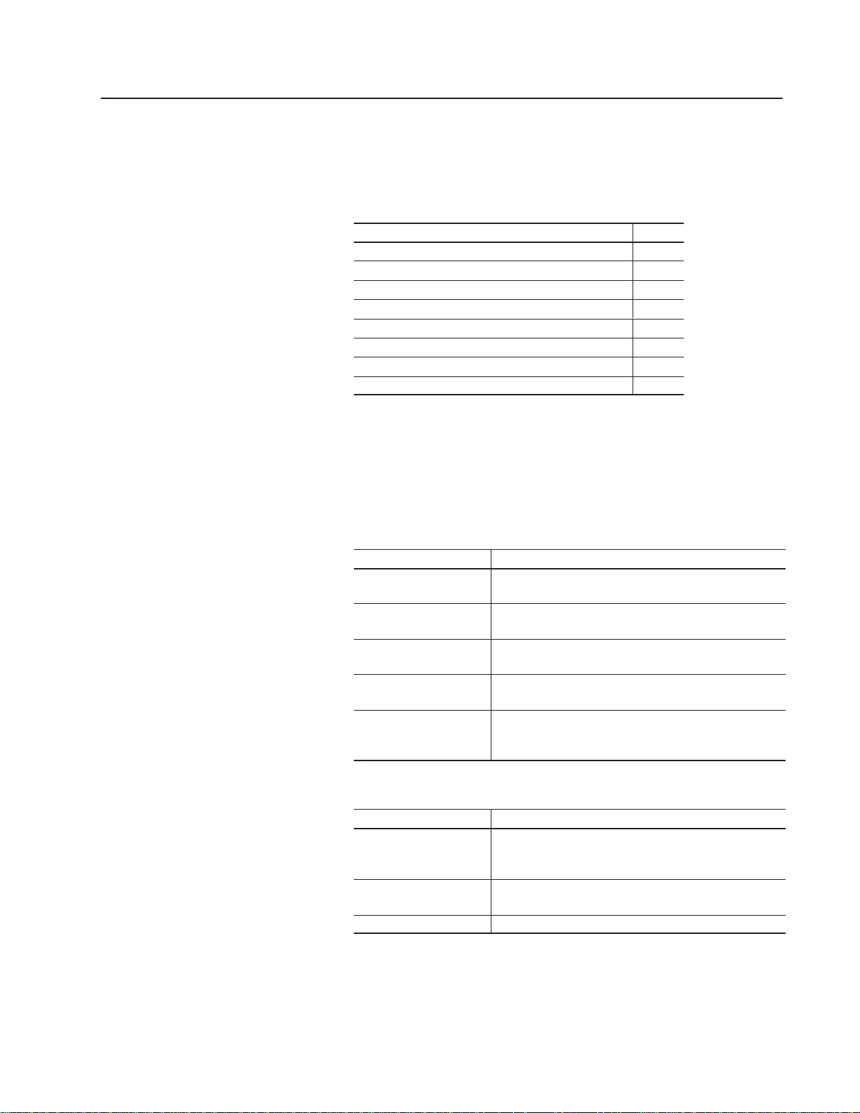
Application Screens
Keypad Terminal
Motor Speed Screen
The Motor Speed screen allows you to:
• monitor motor speed
• increase or decrease motor speed
• enter a new motor speed
• go to the Motor Status screen
Touch Screen Terminal
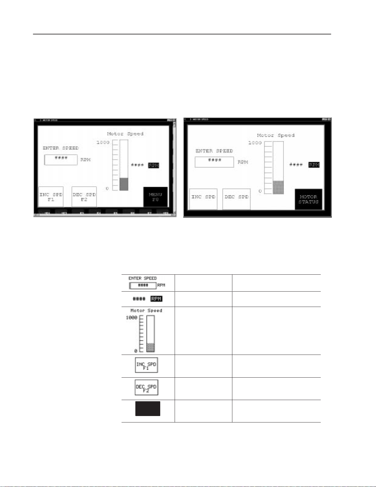
The table below lists objects on the Motor Speed screen and each
object’s function. Object headings are created as background text.
Object Object Type Function
Motor
Status
F8
Numeric Cursor Point
with Background Text
Numeric Data Display Displays the current speed (0 to 1000
Bar Graph and Scale
with Background Text
Momentary Push Button
(Normally Open)
Momentary Push Button
(Normally Open)
Goto Screen Button Displays the Motor Status screen when
Opens the scratchpad for entering a new
motor speed (from 0 to 1000 rpm).
rpm) of the motor.
Displays the current motor speed (0 to
1000 rpm) in a graphic form.
The bar graph scale and tick-mark labels
are created as separate objects.
Increases the speed of the motor when
you press the F1 key or touch the screen
object.
Decreases the speed of the motor when
you press the F2 key or touch the screen
object.
you press the F8 key (F5 on PV550
terminals) or touch the screen object.
Publication 2711-6.2
 Loading...