

Page 1

Attended Workstations
(Catalog Nos. 2708-DH5B2L & -DH5B4L)
(Series B)
User Manual
ALLEN-BRADLEY
Page 2

Disclaimer
Important User Information
Solid state equipment has operational characteristics differing from those of
electromechanical equipment. “Application Considerations for Solid State
Controls” (Publication SGI-1.1) describes some important differences
between solid state equipment and hard–wired electromechanical devices.
Because of this difference, and also because of the wide variety of uses for
solid state equipment, all persons responsible for applying this equipment
must satisfy themselves that each intended application of this equipment is
acceptable.
In no event will the Allen-Bradley Company be responsible or liable for
indirect or consequential damages resulting from the use or application of
this equipment.
The examples and diagrams in this manual are included solely for illustrative
purposes. Because of the many variables and requirements associated with
any particular installation, the Allen-Bradley Company cannot assume
responsibility or liability for actual use based on the examples and diagrams.
No patent liability is assumed by Allen-Bradley Company with respect to use
of information, circuits, equipment, or software described in this manual.
Reproduction of the contents of this manual, in whole or in part, without
written permission of the Allen-Bradley Company is prohibited.
Page 3

Table of Contents
Attended Workstations
User Manual
Introduction
Installing a Network
Chapter Objectives 1–1. . . . . . . . . . . . . . . . . . . . . . . . . . . . . . . . . . . . . . . . .
Catalog Numbers 1–1. . . . . . . . . . . . . . . . . . . . . . . . . . . . . . . . . . . . . . . . . .
Accessory Items 1–1. . . . . . . . . . . . . . . . . . . . . . . . . . . . . . . . . . . . . . . . . . .
Related Publications 1–2. . . . . . . . . . . . . . . . . . . . . . . . . . . . . . . . . . . . . . .
Safety Information 1–2. . . . . . . . . . . . . . . . . . . . . . . . . . . . . . . . . . . . . . . . .
Chapter Objectives 2–1. . . . . . . . . . . . . . . . . . . . . . . . . . . . . . . . . . . . . . . . .
Power Requirements 2–2. . . . . . . . . . . . . . . . . . . . . . . . . . . . . . . . . . . . . . .
Simple Network 2–2. . . . . . . . . . . . . . . . . . . . . . . . . . . . . . . . . . . . . . . . . . .
The RS-485 Network Bus 2–2. . . . . . . . . . . . . . . . . . . . . . . . . . . . . . . .
The Network Connector (Catalog No. 2708-NNC) 2–3. . . . . . . . . . . . .
Cabling a Network Using the Network Connector 2–4. . . . . . . . . . . . .
Cable Wire 2–4. . . . . . . . . . . . . . . . . . . . . . . . . . . . . . . . . . . . . . . .
Preparing the Wire 2–4. . . . . . . . . . . . . . . . . . . . . . . . . . . . . . . . . .
Installing the Connector 2–5. . . . . . . . . . . . . . . . . . . . . . . . . . . . . .
Master Connection 2–5. . . . . . . . . . . . . . . . . . . . . . . . . . . . . . . . . .
NON-MASTER Connection 2–6. . . . . . . . . . . . . . . . . . . . . . . . . . .
Step By Step Installation 2–7. . . . . . . . . . . . . . . . . . . . . . . . . . . . . . . . . . . .
The Terminator Switch 2–9. . . . . . . . . . . . . . . . . . . . . . . . . . . . . . . . . . .
Communication Cables 2–9. . . . . . . . . . . . . . . . . . . . . . . . . . . . . . .
Testing the Network for Data Transmission 2–10. . . . . . . . . . . . . . . . . . . . .
Communication to the Host Computer 2–11. . . . . . . . . . . . . . . . . . . . . . . . .
Description of Large or Complex Network 2–13. . . . . . . . . . . . . . . . . . . . . .
Complex Network 2–13. . . . . . . . . . . . . . . . . . . . . . . . . . . . . . . . . . . . . . . . .
Alternate Communication Links 2–14. . . . . . . . . . . . . . . . . . . . . . . . . . .
Networks Over Telecommunications Lines 2–15. . . . . . . . . . . . . . . . . . .
Barcode Connection
Status Displays
Chapter Objectives 3–1. . . . . . . . . . . . . . . . . . . . . . . . . . . . . . . . . . . . . . . . .
Connection 3–1. . . . . . . . . . . . . . . . . . . . . . . . . . . . . . . . . . . . . . . . . . . . . . .
Introduction 4–1. . . . . . . . . . . . . . . . . . . . . . . . . . . . . . . . . . . . . . . . . . . . . .
Summary Status Display (Status Display 0) 4–2. . . . . . . . . . . . . . . . . . . . .
Network Status (Status Display 1) 4–4. . . . . . . . . . . . . . . . . . . . . . . . . . . . .
Reserved Status (Status Display 2) 4–5. . . . . . . . . . . . . . . . . . . . . . . . . . . .
Time Status (Status Display 3) 4–5. . . . . . . . . . . . . . . . . . . . . . . . . . . . . . .
System Reset Status (Status Display 4) 4–5. . . . . . . . . . . . . . . . . . . . . . . . .
A – Error Codes 4–6. . . . . . . . . . . . . . . . . . . . . . . . . . . . . . . . . . . . . . . . . . .
Network Queue Status (Status Display 5) 4–6. . . . . . . . . . . . . . . . . . . . . . .
Workstation Memory Status (Status Display 6) 4–8. . . . . . . . . . . . . . . . . .
i
Page 4

Table of Contents
Attended Workstations
User Manual
Program Load Status (Status Display 7) 4–9. . . . . . . . . . . . . . . . . . . . . . . .
Program Run Status (Status Display 8) 4–10. . . . . . . . . . . . . . . . . . . . . . . . .
Application Status (Status Display 9) 4–11. . . . . . . . . . . . . . . . . . . . . . . . . .
Configuration Menus
Introduction 5–1. . . . . . . . . . . . . . . . . . . . . . . . . . . . . . . . . . . . . . . . . . . . . .
Using Menus via Workstation Keypad 5–1. . . . . . . . . . . . . . . . . . . . . . . . .
Sub-Menus 5–2. . . . . . . . . . . . . . . . . . . . . . . . . . . . . . . . . . . . . . . . . . . . . . .
Exiting Network Menu 5–2. . . . . . . . . . . . . . . . . . . . . . . . . . . . . . . . . . .
Using Menus from
the Comm Port 5–3. . . . . . . . . . . . . . . . . . . . . . . . . . . . . . . . . . . . . . . . .
Menu 1: Network Menu Paramters 5–4. . . . . . . . . . . . . . . . . . . . . . . . . . . .
Workstation 5–4. . . . . . . . . . . . . . . . . . . . . . . . . . . . . . . . . . . . . . . .
Workstation Type 5–4. . . . . . . . . . . . . . . . . . . . . . . . . . . . . . . . . . .
Menu 2: Comm Port Menu Parameters 5–5. . . . . . . . . . . . . . . . . . . . . . . . .
Comm Port Mode 5–5. . . . . . . . . . . . . . . . . . . . . . . . . . . . . . . . . . .
Comm Baud Rate 5–6. . . . . . . . . . . . . . . . . . . . . . . . . . . . . . . . . . .
Comm Data Bits 5–6. . . . . . . . . . . . . . . . . . . . . . . . . . . . . . . . . . . .
Comm Parity 5–6. . . . . . . . . . . . . . . . . . . . . . . . . . . . . . . . . . . . . . .
Menu 3: System Menu Parameters 5–8. . . . . . . . . . . . . . . . . . . . . . . . . . . .
Menu 4: Bar Code Menu Parameters 5–8. . . . . . . . . . . . . . . . . . . . . . . . . .
Menu 5: Read Only Menu 5–10. . . . . . . . . . . . . . . . . . . . . . . . . . . . . . . . . . .
Menu 6: Diagnostics Menu Parameters 5–10. . . . . . . . . . . . . . . . . . . . . . . . .
1–Keypad/Laser Test 5–11. . . . . . . . . . . . . . . . . . . . . . . . . . . . . . . . . . . . . . .
2–Display Test 5–12. . . . . . . . . . . . . . . . . . . . . . . . . . . . . . . . . . . . . . . . .
3–Destructive RAM Test 5–12. . . . . . . . . . . . . . . . . . . . . . . . . . . . . . . . .
4–Continuous RAM Test 5–13. . . . . . . . . . . . . . . . . . . . . . . . . . . . . . . . .
5–Comm Transmit Test 5–14. . . . . . . . . . . . . . . . . . . . . . . . . . . . . .
6–Comm Receive Test 5–15. . . . . . . . . . . . . . . . . . . . . . . . . . . . . . . . . . . . . .
7–Comm Loop Test 5–15. . . . . . . . . . . . . . . . . . . . . . . . . . . . . . . . . . . . .
8–Aux Comm Transmit Test 5–16. . . . . . . . . . . . . . . . . . . . . . . . . . . . . .
9–Aux Comm Receive Test 5–17. . . . . . . . . . . . . . . . . . . . . . . . . . . . . . .
A–Aux Comm Loopback Test 5–18. . . . . . . . . . . . . . . . . . . . . . . . . . . . . . . .
B–RS485 Block Receive 5–19. . . . . . . . . . . . . . . . . . . . . . . . . . . . . . . . . . . .
C–RS485 Block Transmit 5–19. . . . . . . . . . . . . . . . . . . . . . . . . . . . . . . . . . .
D–RS232 Block Receive 5–20. . . . . . . . . . . . . . . . . . . . . . . . . . . . . . . . . . . .
E–RS232 Block Transmit 5–21. . . . . . . . . . . . . . . . . . . . . . . . . . . . . . . . . . .
F–Lamp Test 5–22. . . . . . . . . . . . . . . . . . . . . . . . . . . . . . . . . . . . . . . . . . . . .
G–Reset Powerup 5–22. . . . . . . . . . . . . . . . . . . . . . . . . . . . . . . . . . . . . . . . .
H–Reset Unit to Factory Defaults 5–22. . . . . . . . . . . . . . . . . . . . . . . . . . . . .
ii
Page 5

Table of Contents
Attended Workstations
User Manual
Operating Procedures
Network Design
Host Communications
Chapter Objectives 6–1. . . . . . . . . . . . . . . . . . . . . . . . . . . . . . . . . . . . . . . . .
Verifying Proper Network Operation 6–2. . . . . . . . . . . . . . . . . . . . . . . . . .
Removing a Master 6–3. . . . . . . . . . . . . . . . . . . . . . . . . . . . . . . . . . . . . . . .
Instituting a New Workstation as Master 6–4. . . . . . . . . . . . . . . . . . . . . . . .
Removing a Workstation from the Network 6–4. . . . . . . . . . . . . . . . . . . . .
Adding a Workstation to the Network 6–5. . . . . . . . . . . . . . . . . . . . . . . . . .
Network Problems 6–5. . . . . . . . . . . . . . . . . . . . . . . . . . . . . . . . . . . . . . . . .
Workstation Status 6–6. . . . . . . . . . . . . . . . . . . . . . . . . . . . . . . . . . . . . . . . .
Networks of 32 Workstations or Less 7–1. . . . . . . . . . . . . . . . . . . . . . . . . .
Network Installation of More than 32 Workstations 7–1. . . . . . . . . . . . . . .
Fault-Tolerant Networks 7–3. . . . . . . . . . . . . . . . . . . . . . . . . . . . . . . . . . . .
Extending Networks Over Phone Lines 7–4. . . . . . . . . . . . . . . . . . . . . . . .
Network Status Records 8–1. . . . . . . . . . . . . . . . . . . . . . . . . . . . . . . . . . . .
Using Retry Counts for Network Diagnosis 8–3. . . . . . . . . . . . . . . . . . . . .
Responses to Network Directives 8–3. . . . . . . . . . . . . . . . . . . . . . . . . . . . .
Network Directives 8–4. . . . . . . . . . . . . . . . . . . . . . . . . . . . . . . . . . . . . . . .
< D – Show Unit Display 8–5. . . . . . . . . . . . . . . . . . . . . . . . . . . . .
< E – Show Last Error Message 8–5. . . . . . . . . . . . . . . . . . . . . . . .
< R – Show Last Reset Message 8–5. . . . . . . . . . . . . . . . . . . . . . .
< S – Show Unit Serial Number 8–6. . . . . . . . . . . . . . . . . . . . . . . .
< T – Show Workstation Date & Time 8–6. . . . . . . . . . . . . . . . . . .
< V – Show Firmware Version 8–6. . . . . . . . . . . . . . . . . . . . . . . . .
> > A – Abort Currently Running A-B VBASIC Program 8–7. . .
> > G – Restart an Aborted BASIC Program 8–7. . . . . . . . . . . . . .
> A – Abort Test 8–7. . . . . . . . . . . . . . . . . . . . . . . . . . . . . . . . . . . .
> C – Send Text Out Comm Port 8–7. . . . . . . . . . . . . . . . . . . . . . .
> c – Send Text Out Aux Comm Port 8–7. . . . . . . . . . . . . . . . . . . .
> D – Display Text on Front Panel 8–7. . . . . . . . . . . . . . . . . . . . . .
> E – Erase the Menu Password 8–8. . . . . . . . . . . . . . . . . . . . . . . .
> F – Reset to Factory Defaults 8–8. . . . . . . . . . . . . . . . . . . . . . . .
> N – Initialize Network 8–8. . . . . . . . . . . . . . . . . . . . . . . . . . . . . .
> R – Reboot Unit 8–8. . . . . . . . . . . . . . . . . . . . . . . . . . . . . . . . . . .
> T – Set Time 8–9. . . . . . . . . . . . . . . . . . . . . . . . . . . . . . . . . . . . .
> Z – Zero Reset Error 8–9. . . . . . . . . . . . . . . . . . . . . . . . . . . . . . .
What is BASIC
Introduction 9–1. . . . . . . . . . . . . . . . . . . . . . . . . . . . . . . . . . . . . . . . . . . . . .
What is Visual BASIC ? 9–1. . . . . . . . . . . . . . . . . . . . . . . . . . . . . . . . . . . .
What is A-B VBASIC? 9–2. . . . . . . . . . . . . . . . . . . . . . . . . . . . . . . . . . . . .
iii
Page 6

Table of Contents
Attended Workstations
User Manual
Developing and Running
An A-B BASIC Program
Step #1 – Planning 10–1. . . . . . . . . . . . . . . . . . . . . . . . . . . . . . . . . . . . . . . . .
The A-B VBASIC Development Procedure 10–1. . . . . . . . . . . . . . . . . . . . .
Step #2 – Coding with the Workstation Application Generator Software . . . .
10–1
Step #3 (Alternate) – Coding with Visual BASIC Editor 10–1. . . . . . . . . . .
Step #4 – Simulation Using Application Library 10–1. . . . . . . . . . . . . . . . .
Step #5 – Compiling the A-B VBASIC Program 10–2. . . . . . . . . . . . . . . . .
Step #6 – Downloading 10–2. . . . . . . . . . . . . . . . . . . . . . . . . . . . . . . . . . . . .
Loading and Auto-Starting an A-B VBASIC Program 10–3. . . . . . . . . . . . .
Start-up Condition of an A-B VBASIC Program 10–3. . . . . . . . . . . . . . . . .
LCD: 10–3. . . . . . . . . . . . . . . . . . . . . . . . . . . . . . . . . . . . . . . . . . . . .
Random numbers: 10–3. . . . . . . . . . . . . . . . . . . . . . . . . . . . . . . . . . .
RAM files: 10–3. . . . . . . . . . . . . . . . . . . . . . . . . . . . . . . . . . . . . . . .
Variables: 10–3. . . . . . . . . . . . . . . . . . . . . . . . . . . . . . . . . . . . . . . . .
Host device: 10–3. . . . . . . . . . . . . . . . . . . . . . . . . . . . . . . . . . . . . . .
Termination of an A-B VBASIC Program 10–4. . . . . . . . . . . . . . . . . . . . . .
A-B VBASIC Run-Time Errors 10–5. . . . . . . . . . . . . . . . . . . . . . . . . . . . . .
Format of a BASIC Error Message 10–5. . . . . . . . . . . . . . . . . . . . . . . . . . . .
Power Failure 10–6. . . . . . . . . . . . . . . . . . . . . . . . . . . . . . . . . . . . . . . . . . . . .
The A-B VBASIC
Cross-Compiler
Special Devices in
A-B VBASIC
iv
Overview 11–1. . . . . . . . . . . . . . . . . . . . . . . . . . . . . . . . . . . . . . . . . . . . . . . .
Invoking the Compiler 11–2. . . . . . . . . . . . . . . . . . . . . . . . . . . . . . . . . . . . . .
LXB param 1 (,param2) (,param3) (,param4) 11–2. . . . . . . . . . . . .
LXB 11–3. . . . . . . . . . . . . . . . . . . . . . . . . . . . . . . . . . . . . . . . . . . . .
LXB Prog1 11–3. . . . . . . . . . . . . . . . . . . . . . . . . . . . . . . . . . . . . . . .
LXB Prog1,Prog1,Prog1 11–3. . . . . . . . . . . . . . . . . . . . . . . . . . . . .
LXB Prog1,Download,PRN 11–3. . . . . . . . . . . . . . . . . . . . . . . . . . .
LXB Prog1,Startnow,Prog1,Wait 11–3. . . . . . . . . . . . . . . . . . . . . . .
A – Source File Specification 11–3. . . . . . . . . . . . . . . . . . . . . . . . . . . . . . . .
B – Downloaded Executable File 11–4. . . . . . . . . . . . . . . . . . . . . . . . . . . . .
C – Listing File 11–4. . . . . . . . . . . . . . . . . . . . . . . . . . . . . . . . . . . . . . . . . . .
D – Secondary Download File 11–4. . . . . . . . . . . . . . . . . . . . . . . . . . . . . . . .
Introduction 12–1. . . . . . . . . . . . . . . . . . . . . . . . . . . . . . . . . . . . . . . . . . . . . .
Device: LCD Display 12–2. . . . . . . . . . . . . . . . . . . . . . . . . . . . . . . . . . . . . .
Device: Keypad 12–3. . . . . . . . . . . . . . . . . . . . . . . . . . . . . . . . . . . . . . . . . . .
Device: Barcode Scanners 12–4. . . . . . . . . . . . . . . . . . . . . . . . . . . . . . . . . . .
When reading barcodes: 12–4. . . . . . . . . . . . . . . . . . . . . . . . . . . . . .
Device: Host Computer 12–6. . . . . . . . . . . . . . . . . . . . . . . . . . . . . . . . . . . . .
Page 7

Table of Contents
Attended Workstations
User Manual
General restrictions and warnings: 12–7. . . . . . . . . . . . . . . . . . . . . .
Details of Specific Statements and Functions 12–8. . . . . . . . . . . . . . . . . . . .
OPEN “HOST” 12–8. . . . . . . . . . . . . . . . . . . . . . . . . . . . . . . . . . . . .
CLOSE “HOST” 12–9. . . . . . . . . . . . . . . . . . . . . . . . . . . . . . . . . . . .
WRITE # 12–9. . . . . . . . . . . . . . . . . . . . . . . . . . . . . . . . . . . . . . . . . .
PUT to HOST 12–9. . . . . . . . . . . . . . . . . . . . . . . . . . . . . . . . . . . . . .
PUT to NET 12–9. . . . . . . . . . . . . . . . . . . . . . . . . . . . . . . . . . . . . . .
PUT to QUE 12–9. . . . . . . . . . . . . . . . . . . . . . . . . . . . . . . . . . . . . . .
PRINT # 12–9. . . . . . . . . . . . . . . . . . . . . . . . . . . . . . . . . . . . . . . . . .
LINE INPUT # for HOST and NET
GET # for HOST and NET (OPEN with RANDOM) 12–10. . . .
LINE INPUT # for QUE
GET # for QUE (OPEN with RANDOM enforced) 12–10. . . . .
EOF for HOST and NET 12–10. . . . . . . . . . . . . . . . . . . . . . . . . . . . .
LOC for HOST and NET 12–10. . . . . . . . . . . . . . . . . . . . . . . . . . . . .
LOF for HOST 12–10. . . . . . . . . . . . . . . . . . . . . . . . . . . . . . . . . . . . .
LOF for NET 12–10. . . . . . . . . . . . . . . . . . . . . . . . . . . . . . . . . . . . . .
IOCTL$ (intrinsic function) for HOST and NET 12–11. . . . . . . . . .
IOCTL (statement) for HOST 12–11. . . . . . . . . . . . . . . . . . . . . . . . .
Devices: Communication Ports, Primary and Auxiliary 12–11. . . . . . . . . . . .
A – Output to a Communication Port 12–12. . . . . . . . . . . . . . . . . . . . . . . . . .
B – Input from a Communication Port 12–12. . . . . . . . . . . . . . . . . . . . . . . . .
C – Modem Control Lines 12–13. . . . . . . . . . . . . . . . . . . . . . . . . . . . . . . . . . .
Device: RAM Files 12–13. . . . . . . . . . . . . . . . . . . . . . . . . . . . . . . . . . . . . . . .
Description: 12–13. . . . . . . . . . . . . . . . . . . . . . . . . . . . . . . . . . . . . . .
File Memory Management 12–14. . . . . . . . . . . . . . . . . . . . . . . . . . . .
Device: Beeper 12–14. . . . . . . . . . . . . . . . . . . . . . . . . . . . . . . . . . . . . . . . . . . .
Device: Front Panel LED’s12–14. . . . . . . . . . . . . . . . . . . . . . . . . . . . . . . . . .
Device: The #9 User Status Display 12–15. . . . . . . . . . . . . . . . . . . . . . . . . . .
Description: 12–15. . . . . . . . . . . . . . . . . . . . . . . . . . . . . . . . . . . . . . .
Device: The Egg Timer 12–16. . . . . . . . . . . . . . . . . . . . . . . . . . . . . . . . . . . . .
Description: 12–16. . . . . . . . . . . . . . . . . . . . . . . . . . . . . . . . . . . . . . .
A-B VBASIC Application
Library
Introduction 13–1. . . . . . . . . . . . . . . . . . . . . . . . . . . . . . . . . . . . . . . . . . . . . .
Using the Library 13–2. . . . . . . . . . . . . . . . . . . . . . . . . . . . . . . . . . . . . . . . . .
Writing Programs 13–3. . . . . . . . . . . . . . . . . . . . . . . . . . . . . . . . . . . . . . . . . .
Using the ENVPC Simulator 13–4. . . . . . . . . . . . . . . . . . . . . . . . . . . . . . . . .
A – Predefined Constants 13–5. . . . . . . . . . . . . . . . . . . . . . . . . . . . . . . . .
B – Global Variables 13–6. . . . . . . . . . . . . . . . . . . . . . . . . . . . . . . . . . . . .
C – BASIC Language Development Kit Limitations 13–7. . . . . . . . . . . .
D – PC Simulation Constants and Variables 13–7. . . . . . . . . . . . . . . . . .
Display and Keyboard 13–8. . . . . . . . . . . . . . . . . . . . . . . . . . . . . . .
Network I/O 13–8. . . . . . . . . . . . . . . . . . . . . . . . . . . . . . . . . . . . . . .
v
Page 8

Table of Contents
Attended Workstations
User Manual
COM and AUX 13–8. . . . . . . . . . . . . . . . . . . . . . . . . . . . . . . . . . . . .
Status Display 13–9. . . . . . . . . . . . . . . . . . . . . . . . . . . . . . . . . . . . . .
Printing Reports and Forms 13–9. . . . . . . . . . . . . . . . . . . . . . . . . . .
2708-DH5B2L and -DH5B4L
Workstation Specifications
Menu Trigger Keys
Technical Description
Workstation Communication
Pin-Out Diagrams
Distance Limitations
Site Parameter List
Electrical – 2708-NP1 A–1. . . . . . . . . . . . . . . . . . . . . . . . . . . . . . . . . . . . . .
Electrical – 2708-NP2 A–1. . . . . . . . . . . . . . . . . . . . . . . . . . . . . . . . . . . . . .
Mechanical – 2708-DH5B2L and -DH5B4L A–1. . . . . . . . . . . . . . . . . . . .
Communication Ports A–1. . . . . . . . . . . . . . . . . . . . . . . . . . . . . . . . . . . . . .
B–1. . . . . . . . . . . . . . . . . . . . . . . . . . . . . . . . . . . . . . . . . . . . . . . . . . . . . . . .
C–1. . . . . . . . . . . . . . . . . . . . . . . . . . . . . . . . . . . . . . . . . . . . . . . . . . . . . . . .
D–1. . . . . . . . . . . . . . . . . . . . . . . . . . . . . . . . . . . . . . . . . . . . . . . . . . . . . . . .
Network (RS-485) Cable Length E–1. . . . . . . . . . . . . . . . . . . . . . . . . . . . . .
RS-232 (MASTER or HOST) Cable Length E–1. . . . . . . . . . . . . . . . . . . . .
F–1. . . . . . . . . . . . . . . . . . . . . . . . . . . . . . . . . . . . . . . . . . . . . . . . . . . . . . . .
Network Pin-Out Diagrams
for DB9 Connector
Error Messages and Prompts
Time Display Formats
VBASIC Language
Development Kit
Programming Conventions
and Tips
vi
G–1. . . . . . . . . . . . . . . . . . . . . . . . . . . . . . . . . . . . . . . . . . . . . . . . . . . . . . . .
H–1. . . . . . . . . . . . . . . . . . . . . . . . . . . . . . . . . . . . . . . . . . . . . . . . . . . . . . . .
I–1. . . . . . . . . . . . . . . . . . . . . . . . . . . . . . . . . . . . . . . . . . . . . . . . . . . . . . . .
Programming Conventions J–1. . . . . . . . . . . . . . . . . . . . . . . . . . . . . . . . . .
Programming Tips J–2. . . . . . . . . . . . . . . . . . . . . . . . . . . . . . . . . . . . . . . . .
Page 9

Table of Contents
Attended Workstations
User Manual
A-B VBASIC and
Visual BASIC Tips
Differences Between
A-B VBASIC and
Visual BASIC
Misspellings K–1. . . . . . . . . . . . . . . . . . . . . . . . . . . . . . . . . . . . . . . . . . . . . .
Strings in TYPEs K–1. . . . . . . . . . . . . . . . . . . . . . . . . . . . . . . . . . . . . . . . . .
Variables Beginning with “FN” K–1. . . . . . . . . . . . . . . . . . . . . . . . . . . . . . .
Accidental Omission of %, &, ! # OR $ K–1. . . . . . . . . . . . . . . . . . . . . . . .
Use of Colons as Statement Separators K–1. . . . . . . . . . . . . . . . . . . . . . . . .
CONSTant Declarations K–2. . . . . . . . . . . . . . . . . . . . . . . . . . . . . . . . . . . .
PRINT “text”; : <statement> K–2. . . . . . . . . . . . . . . . . . . . . . . . . . . . . . . . .
General Restrictions L–1. . . . . . . . . . . . . . . . . . . . . . . . . . . . . . . . . . . . . . . .
Supported A-B VBASIC Keywords L–1. . . . . . . . . . . . . . . . . . . . . . . . . . .
ABS(numeric–expression) L–2. . . . . . . . . . . . . . . . . . . . . . . . . . . . . . . .
ASC(string–expression) L–2. . . . . . . . . . . . . . . . . . . . . . . . . . . . . . . . . .
BEEP L–2. . . . . . . . . . . . . . . . . . . . . . . . . . . . . . . . . . . . . . . . . . . . . . . .
CDBL(numeric–expression) L–2. . . . . . . . . . . . . . . . . . . . . . . . . . . . . .
CHAIN filespec L–2. . . . . . . . . . . . . . . . . . . . . . . . . . . . . . . . . . . . . . . .
CHR$(code) L–3. . . . . . . . . . . . . . . . . . . . . . . . . . . . . . . . . . . . . . . . . . .
CINT(numeric–expression) L–3. . . . . . . . . . . . . . . . . . . . . . . . . . . . . . .
CLNG(numeric–expression) L–3. . . . . . . . . . . . . . . . . . . . . . . . . . . . . .
CLOSE [ [#]filenumber[,[#]filenumber]...] L–3. . . . . . . . . . . . . . . . . . .
CLS [{ 0 | 1 | 2 }] L–3. . . . . . . . . . . . . . . . . . . . . . . . . . . . . . . . . . . . . . .
CONST constname=expression L–4. . . . . . . . . . . . . . . . . . . . . . . . . . . .
CSNG(numeric–expression) L–4. . . . . . . . . . . . . . . . . . . . . . . . . . . . . .
CSRLIN L–4. . . . . . . . . . . . . . . . . . . . . . . . . . . . . . . . . . . . . . . . . . . . . .
CVI, CVS, CVL, (CVD) L–4. . . . . . . . . . . . . . . . . . . . . . . . . . . . . . . . .
DATE$ L–4. . . . . . . . . . . . . . . . . . . . . . . . . . . . . . . . . . . . . . . . . . . . . . .
DATE$ = ”yymmddw” L–4. . . . . . . . . . . . . . . . . . . . . . . . . . . . . . . . . . .
DECLARE {FUNCTION | SUB} name(parameters) L–5. . . . . . . . . . .
DEFINT letterrange[,letterrange]... L–5. . . . . . . . . . . . . . . . . . . . . . . . .
DEFSNG letterrange[,letterrange]... L–5. . . . . . . . . . . . . . . . . . . . . . . . .
(DEFDBL letterrange[,letterrange]...) No longer supported L–5. . . . . .
DEFLNG letterrange[,letterrange]... L–5. . . . . . . . . . . . . . . . . . . . . . . .
DEFSTR letterrange[,letterrange]... L–5. . . . . . . . . . . . . . . . . . . . . . . . .
DIM [SHARED] variable[(subscripts)][AS type]... L–6. . . . . . . . . . . . .
DO...LOOP [{WHILE/UNTIL} booleanexpression] L–6. . . . . . . . . . .
END [{FUNCTION/IF/SELECT/SUB/TYPE}] L–6. . . . . . . . . . . . . . .
EOF(filenumber) L–6. . . . . . . . . . . . . . . . . . . . . . . . . . . . . . . . . . . . . . .
FIX(x) L–7. . . . . . . . . . . . . . . . . . . . . . . . . . . . . . . . . . . . . . . . . . . . . . . .
FOR counter = start TO end [STEP increment]
...
NEXT [counter] L–7. . . . . . . . . . . . . . . . . . . . . . . . . . . . . . . . . . . . .
vii
Page 10

Table of Contents
Attended Workstations
User Manual
viii
FRE(numeric expression) L–8. . . . . . . . . . . . . . . . . . . . . . . . . . . . . . . . .
FREEFILE L–8. . . . . . . . . . . . . . . . . . . . . . . . . . . . . . . . . . . . . . . . . . . .
FUNCTION name[(parameterlist)][STATIC] L–8. . . . . . . . . . . . . . . . .
GET [#]filenumber[,[recordnumber][,variable]] L–8. . . . . . . . . . . . . . .
GOSUB {linelabel | linenumber}....RETURN L–9. . . . . . . . . . . . . . . . .
GOTO {linelabel/linenumber} L–9. . . . . . . . . . . . . . . . . . . . . . . . . . . . .
HEX$(expression) L–9. . . . . . . . . . . . . . . . . . . . . . . . . . . . . . . . . . . . . .
IF...THEN...ELSE L–9. . . . . . . . . . . . . . . . . . . . . . . . . . . . . . . . . . . . . .
INKEY$ L–10. . . . . . . . . . . . . . . . . . . . . . . . . . . . . . . . . . . . . . . . . . . . . .
INPUT$(bytecount[,[#]filenumber]) L–10. . . . . . . . . . . . . . . . . . . . . . . .
INSTR([start,]stringexpression1,stringexpression2) L–10. . . . . . . . . . . .
INT(numeric–expression) L–10. . . . . . . . . . . . . . . . . . . . . . . . . . . . . . . .
IOCTL$([#]filenumber) L–10. . . . . . . . . . . . . . . . . . . . . . . . . . . . . . . . . .
IOCTL[#]filenumber,string L–11. . . . . . . . . . . . . . . . . . . . . . . . . . . . . . .
KILL “filespec” L–11. . . . . . . . . . . . . . . . . . . . . . . . . . . . . . . . . . . . . . . .
LBOUND(array[,dimension]) L–11. . . . . . . . . . . . . . . . . . . . . . . . . . . . .
LCASE$(stringexpression) L–11. . . . . . . . . . . . . . . . . . . . . . . . . . . . . . .
LEFT$(stringexpression, n) L–11. . . . . . . . . . . . . . . . . . . . . . . . . . . . . . .
LEN(stringexpression) L–12. . . . . . . . . . . . . . . . . . . . . . . . . . . . . . . . . . .
LEN(variable) L–12. . . . . . . . . . . . . . . . . . . . . . . . . . . . . . . . . . . . . . . . . .
LINE INPUT[;][“promptstring”;]stringvariable L–12. . . . . . . . . . . . . . .
LINE INPUT #filenumber,stringvariable L–12. . . . . . . . . . . . . . . . . . . . .
LOC(filenumber) L–12. . . . . . . . . . . . . . . . . . . . . . . . . . . . . . . . . . . . . . .
LOCATE[row][,[column][,[cursor]]] L–13. . . . . . . . . . . . . . . . . . . . . . . .
LOF(filenumber) L–13. . . . . . . . . . . . . . . . . . . . . . . . . . . . . . . . . . . . . . .
LTRIM$(stringexpression) L–13. . . . . . . . . . . . . . . . . . . . . . . . . . . . . . . .
MID$(stringexpression, start[, length]) L–13. . . . . . . . . . . . . . . . . . . . . .
MKD$, MKI$, MKL$, MKS$ L–13. . . . . . . . . . . . . . . . . . . . . . . . . . . . .
OCT$(numeric–expression) L–14. . . . . . . . . . . . . . . . . . . . . . . . . . . . . . .
ON expression GOSUB {line–number–list/line–label–list} L–14. . . . . .
ON expression GOTO {line–number–list/line–label–list} L–14. . . . . . .
OPEN file [FOR mode1][ACCESS] AS[#]filenum [LEN=reclen] L–14.
POS(0) L–14. . . . . . . . . . . . . . . . . . . . . . . . . . . . . . . . . . . . . . . . . . . . . . .
PRINT [expressionlist][{,|;}] L–14. . . . . . . . . . . . . . . . . . . . . . . . . . . . . .
PRINT #filenumber,[USING stringexpression;] expressionlist[{,|;}] L–15
PRINT USING formatstring; expressionlist[{,|;}] L–15. . . . . . . . . . . . . .
PUT [#]filenumber[,[recordnumber][,variable]] L–15. . . . . . . . . . . . . . .
RANDOMIZE expression L–15. . . . . . . . . . . . . . . . . . . . . . . . . . . . . . . .
REM remark
‘ remark L–16. . . . . . . . . . . . . . . . . . . . . . . . . . . . . . . . . . . . . . . . . . .
RETURN L–16. . . . . . . . . . . . . . . . . . . . . . . . . . . . . . . . . . . . . . . . . . . . .
RIGHT$(stringexpression, n) L–16. . . . . . . . . . . . . . . . . . . . . . . . . . . . . .
RND L–16. . . . . . . . . . . . . . . . . . . . . . . . . . . . . . . . . . . . . . . . . . . . . . . . .
RTRIM$(stringexpression) L–16. . . . . . . . . . . . . . . . . . . . . . . . . . . . . . . .
Page 11

Table of Contents
Attended Workstations
User Manual
SEEK(filenumber) L–16. . . . . . . . . . . . . . . . . . . . . . . . . . . . . . . . . . . . . .
SEEK [#]filenumber,position L–16. . . . . . . . . . . . . . . . . . . . . . . . . . . . . .
SELECT CASE text_expression L–17. . . . . . . . . . . . . . . . . . . . . . . . . . .
SGN(numeric–expression) L–17. . . . . . . . . . . . . . . . . . . . . . . . . . . . . . . .
SHARED variable [AS type] [,variable [AS type]]... L–17. . . . . . . . . . .
SLEEP seconds L–17. . . . . . . . . . . . . . . . . . . . . . . . . . . . . . . . . . . . . . . . .
SOUND frequency,duration L–18. . . . . . . . . . . . . . . . . . . . . . . . . . . . . . .
SPACE$(n) L–18. . . . . . . . . . . . . . . . . . . . . . . . . . . . . . . . . . . . . . . . . . . .
STATIC variablelist L–18. . . . . . . . . . . . . . . . . . . . . . . . . . . . . . . . . . . . .
STOP L–18. . . . . . . . . . . . . . . . . . . . . . . . . . . . . . . . . . . . . . . . . . . . . . . .
STR$(numeric–expression) L–18. . . . . . . . . . . . . . . . . . . . . . . . . . . . . . .
STRING$(m,n) L–19. . . . . . . . . . . . . . . . . . . . . . . . . . . . . . . . . . . . . . . . .
STRING$(m,stringexpression) L–19. . . . . . . . . . . . . . . . . . . . . . . . . . . . .
SUB globalname[(parameterlist)][STATIC]
...
...
Application Library
Subroutines
A-B VBASIC Limits
END SUB L–19. . . . . . . . . . . . . . . . . . . . . . . . . . . . . . . . . . . . . . . . . .
SWAP vari1,vari2 L–19. . . . . . . . . . . . . . . . . . . . . . . . . . . . . . . . . . . . . . .
SYSTEM L–19. . . . . . . . . . . . . . . . . . . . . . . . . . . . . . . . . . . . . . . . . . . . .
TIME$ L–20. . . . . . . . . . . . . . . . . . . . . . . . . . . . . . . . . . . . . . . . . . . . . . .
TIME$ = stringexpression L–20. . . . . . . . . . . . . . . . . . . . . . . . . . . . . . . .
TIMER L–20. . . . . . . . . . . . . . . . . . . . . . . . . . . . . . . . . . . . . . . . . . . . . . .
TYPE usertype L–20. . . . . . . . . . . . . . . . . . . . . . . . . . . . . . . . . . . . . . . . .
END TYPE L–20. . . . . . . . . . . . . . . . . . . . . . . . . . . . . . . . . . . . . . . . . . . .
UBOUND(array[,dimension]) L–21. . . . . . . . . . . . . . . . . . . . . . . . . . . . .
UCASE$(stringexpression) L–21. . . . . . . . . . . . . . . . . . . . . . . . . . . . . . .
VAL(stringexpression) L–21. . . . . . . . . . . . . . . . . . . . . . . . . . . . . . . . . . .
WHILE condition L–21. . . . . . . . . . . . . . . . . . . . . . . . . . . . . . . . . . . . . . .
WEND L–21. . . . . . . . . . . . . . . . . . . . . . . . . . . . . . . . . . . . . . . . . . . . . . .
WRITE #filenumber [,expressionlist] L–21. . . . . . . . . . . . . . . . . . . . . . .
In ENV.BAS and ENVPC.BAS M–1. . . . . . . . . . . . . . . . . . . . . . . . . . . . . . .
In READ.BAS M–1. . . . . . . . . . . . . . . . . . . . . . . . . . . . . . . . . . . . . . . . . . . .
In MENU.BAS M–1. . . . . . . . . . . . . . . . . . . . . . . . . . . . . . . . . . . . . . . . . . .
In TRIG.BAS M–2. . . . . . . . . . . . . . . . . . . . . . . . . . . . . . . . . . . . . . . . . . . . .
In HYP.BAS M–2. . . . . . . . . . . . . . . . . . . . . . . . . . . . . . . . . . . . . . . . . . . . . .
N–1. . . . . . . . . . . . . . . . . . . . . . . . . . . . . . . . . . . . . . . . . . . . . . . . . . . . . . . .
ix
Page 12

Chapter
Chapter Objectives
A–B
1
Introduction
Allen-Bradley workstations are designed to be rugged and very reliable when
installed using the correct voltage and network cabling. An inexpensive
network connector (Catalog No. 2708-NNC) has been designed in order to
simplify the network installation. Although the workstations may be securely
installed without this connector, it is highly recommended that this connector
be used. The time saved and the ease of installation will be significant.
Chapters 2 through 4 describe network installation, host communication, and
the connection of barcode scanners.
Installation of a network includes cabling (both power and network) and
configuration of the workstations. In some instances, it may be necessary to
consult Chapters 5 through 8 for detailed information on the proper ways to
configure the workstations.
Catalog Numbers
Accessory Items
Item Catalog No. Description
DH5 Power Supply, U.S. 2708-NP1 Accepts 120V AC input power.
DH5 Power Supply, Europe 2708-NP2 Accepts 240V AC input power.
DH5 Network Connector 2708-NNC
Application Generator Software 2708-NAG
Network Manager Software 2708-NNM
Basic Language Development Kit
Software
Hand-Held Scanner 2755-G3, -G6 Visible laser diode, moving beam, hand-held scanner for bar codes.
Bar Code Wand 2755-W1 Visible red light source (high density bar codes).
Bar Code Wand 2755-W2 Visible red light source (low density bar codes).
Bar Code Wand 2755-W5 Infrared light source (high density bar codes).
Slot Scanner 2755-B1, -B2 Slot scanner for bar codes.
The catalog numbers covered by this manual include Attended Workstations
2708-DH5B2L and 2708-DH5B4L.
Accessory items for the 2708-DH5B2L and -DH5B4L workstations are listed
below:
Communications port connector that may be wired for point-to-point or
multidrop applications.
Menu-driven development software package for custom application
programming. Includes Catalog Nos. 2708–NNM and –NBD.
Terminal emulator software utilities package that allows the workstation to
be configured for a variety of network configurations.
2708-NBD
Contains a set of source files that can be used to reduce program
development time.
1–1
Page 13
Chapter 1
Introduction
Related Publications
Publication No. Title Purpose of Publication
2708-801 Application Generator User’s Manual
2708-802 Network Manager User’s Manual
2708-803 Basic Language Kit User’s Manual
2708-2.3
Safety Information
A-B VBASIC vs. Visual BASICt
The following table lists the publications that are available:
Describes how to use Application Generator Software to create
custom application programs.
Describes how to use the Network Manager Software to
configure the workstation for a variety of network configurations.
Describes how to use the Basic Language Kit source files to
reduce program development time.
Describes the differences between standard Visual BASICt
and the Allen-Bradley VBASIC modified for use with the
2708-DH5B_L workstation.
Throughout this manual we use notes to make you aware of safety
considerations.
ATTENTION: Identifies information about practices or
circumstances that can lead to personal injury or death, property
!
damage, or economic loss.
Important: Identifies information that is especially important for successful
application and understanding of the product.
1–2
Page 14
Chapter
Chapter Objectives
A–B
2
Installing a Network
The physical network is based on a twisted pair cabling technique that
follows the Electronic Industrial Association (EIA) RS-485 standard. This
standard specifies the electrical characteristics of the balanced voltage digital
interface circuit. This electrical standard is similar to the more familiar
RS-422 standard. The RS-485 communication drivers are capable of
withstanding greater voltage surges and tolerating more installation errors
than standard RS-422 communications.
The RS-485 network cabling system used by the workstations is a
daisy-chain (or multidrop) architecture. Each workstation is directly
connected to its neighbor. An example of this multidrop architecture is
shown in Figure 2.1.
Figure 2.1
RS-485 Multidrop Architecture
Network Connector
(Catalog No. 2708-NNC)
RS-232 or RS-422
From Host
Master
Although the workstations in the network may be physically identical, the
network role of an individual workstation may be different from its neighbor.
The seven possible network configurations are:
Normal Standard Workstation
Master Communicates with host computer via COM1
Alternate Backup for the Master
Concentrator Connects Submaster to backbone network
Submaster Connects tributary to Concentrator
Alt Submaster Backup for Submaster
Gateway Master/Concentrator
Normal
RS-485
Normal Normal
To Other
Workstations
These configurations are described in Chapters 5 through 8 along with
workstation set-up instructions. It is necessary to understand the
configuration set-up to be able to wire the network properly.
The network check out may be entirely accomplished by using the diagnostic
tests resident in the workstations.
2–1
Page 15
Chapter 2
Installing a Network
Simple Network
ALLEN-BRADLEY
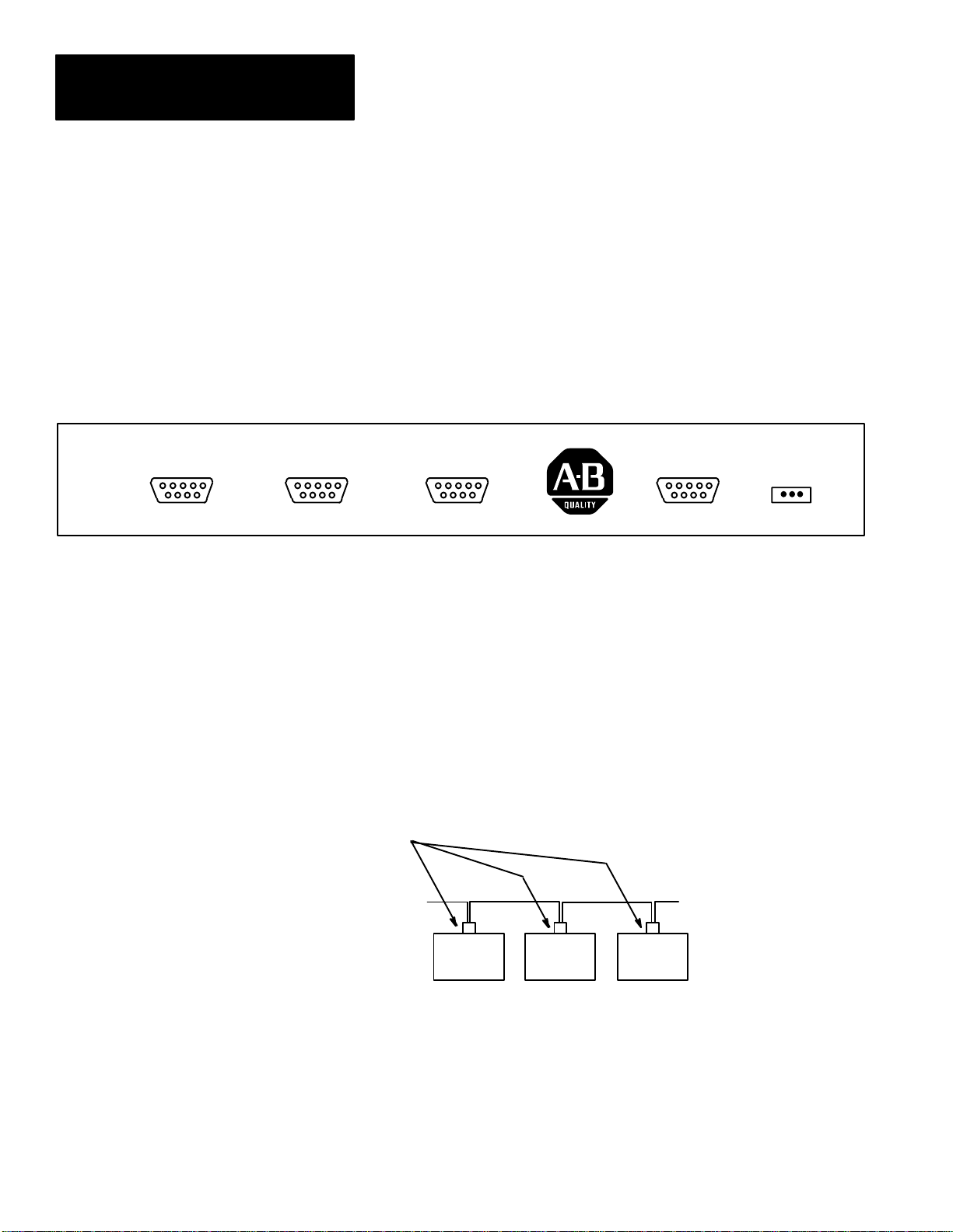
Power Requirements
Each workstation must be powered with 28V of AC power. This power is
supplied by the power supply (Catalog No. 2708-NP1, -NP2) which is a
sealed AC adaptor that is plugged into a wall outlet. The power output cable
is plugged into the power connector as shown in Figure 2. A full diagram of
all the connectors is shown in Figure 2.2.
Figure 2.2
Back Plate of the Workstation
MADE IN USA
485 NETCOM1COM2
BARCODE PWR
In a normal installation, each individual workstation is powered by its own
power supply.
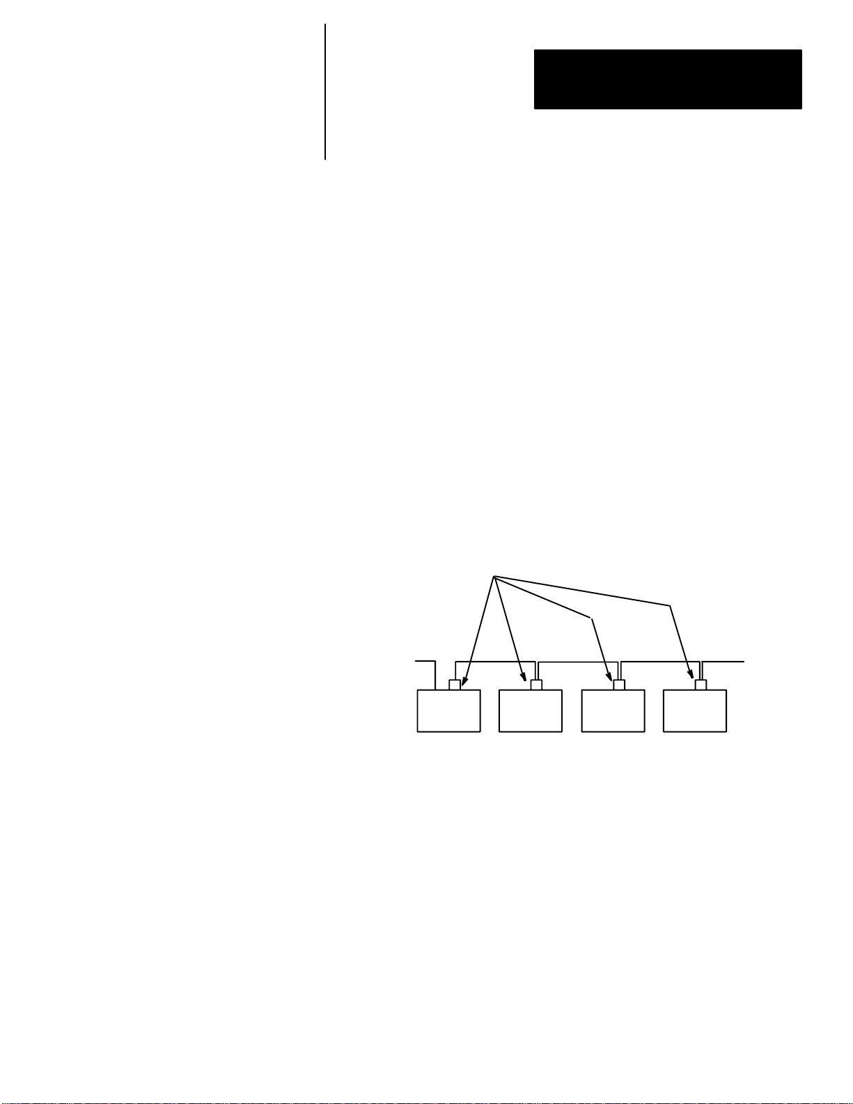
The RS-485 Network Bus
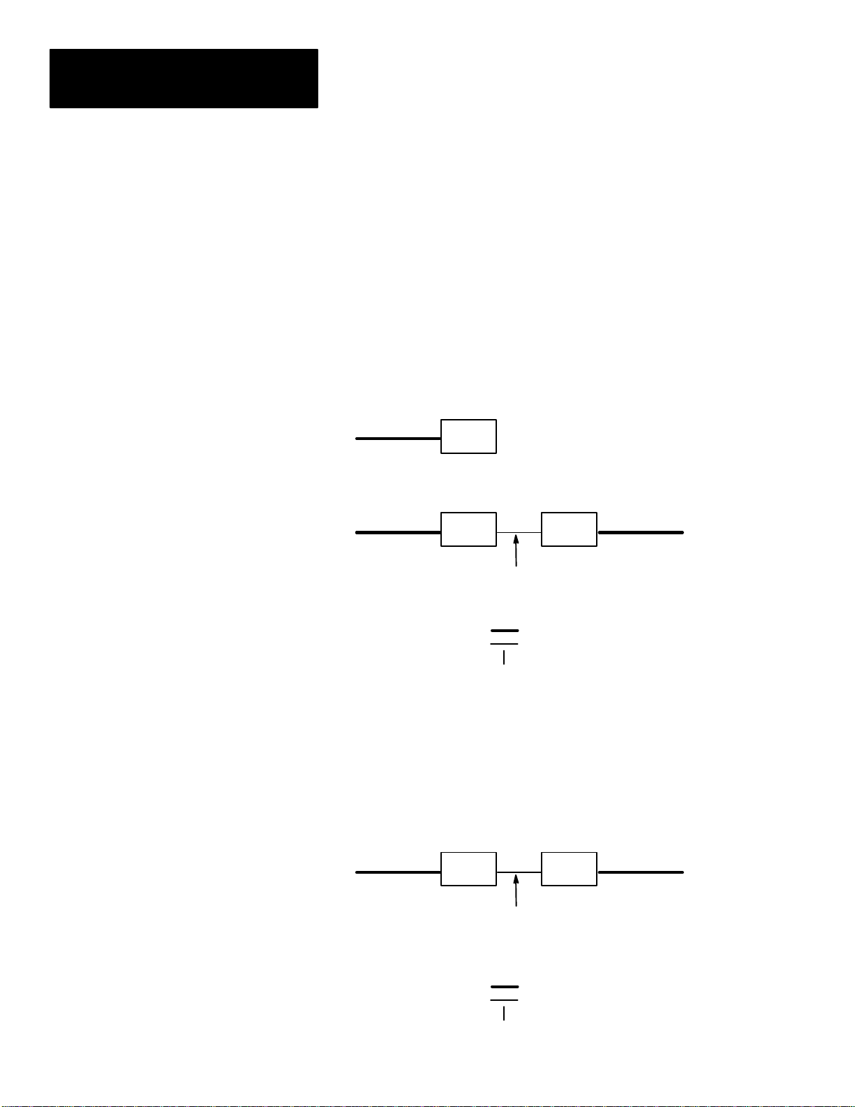
It is highly important to recognize that the network should be wired to appear
as a continuous cable or bus and should not be spliced in a manner that
allows the cable to make a 3-way junction. Figure 2.3 shows the right way to
wire a network.
Figure 2.3
Correct Network Connection
Network
Connector
Workstation
Workstation
Workstation
2–2
Page 16

Chapter 2
Installing a Network
Simple Network (cont’d)
Figure 2.3 shows the correct method of wiring a network. This figure shows
the cable coming into the Network Connector (Catalog No. 2708-NNC) and
making connection with the cable coming out of the connector. If the
workstations are removed from their respective network connectors, it is easy
to determine that a continuous cable or bus has been created.
The network is a signal transmission line and cannot be treated the same as a
power voltage line. The transmission line operates at considerably higher
frequencies and therefore must be properly wired and terminated (resistance
loaded). If this network transmission line is not installed properly, as shown
in Figure 2.3, then voltage standing wave reflections (VSWR) and various
other propagation phenomenon may occur.
This could cause workstations to not come on-line, drop off and on-line, or
have multiple communication retrys in order to make a signal connection.
ATTENTION: It must be emphasized that the network cable be
installed as a transmission line and not as a power voltage line.
!
As discussed in this section, a simple network consists of a single cable to
connect up to 32 workstations. This is called a “backbone” network and is
diagramed on Figure 2.4.
Figure 2.4
Simple Network Configuration
Host M—W—W—W—W—W—W—W—W—W
W Workstation
M Master
Indicates RS-232
Indicates RS-485 backbone
No more than 32 workstations can be connected to the same network cable.
If more than 32 workstations are required, refer to the Complex Networks
section.
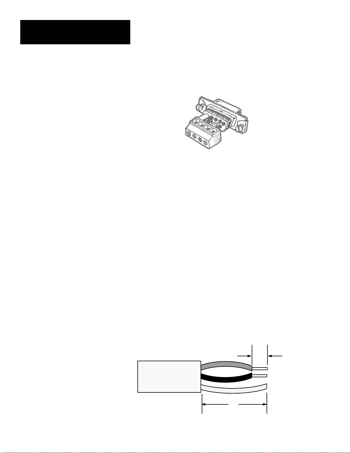
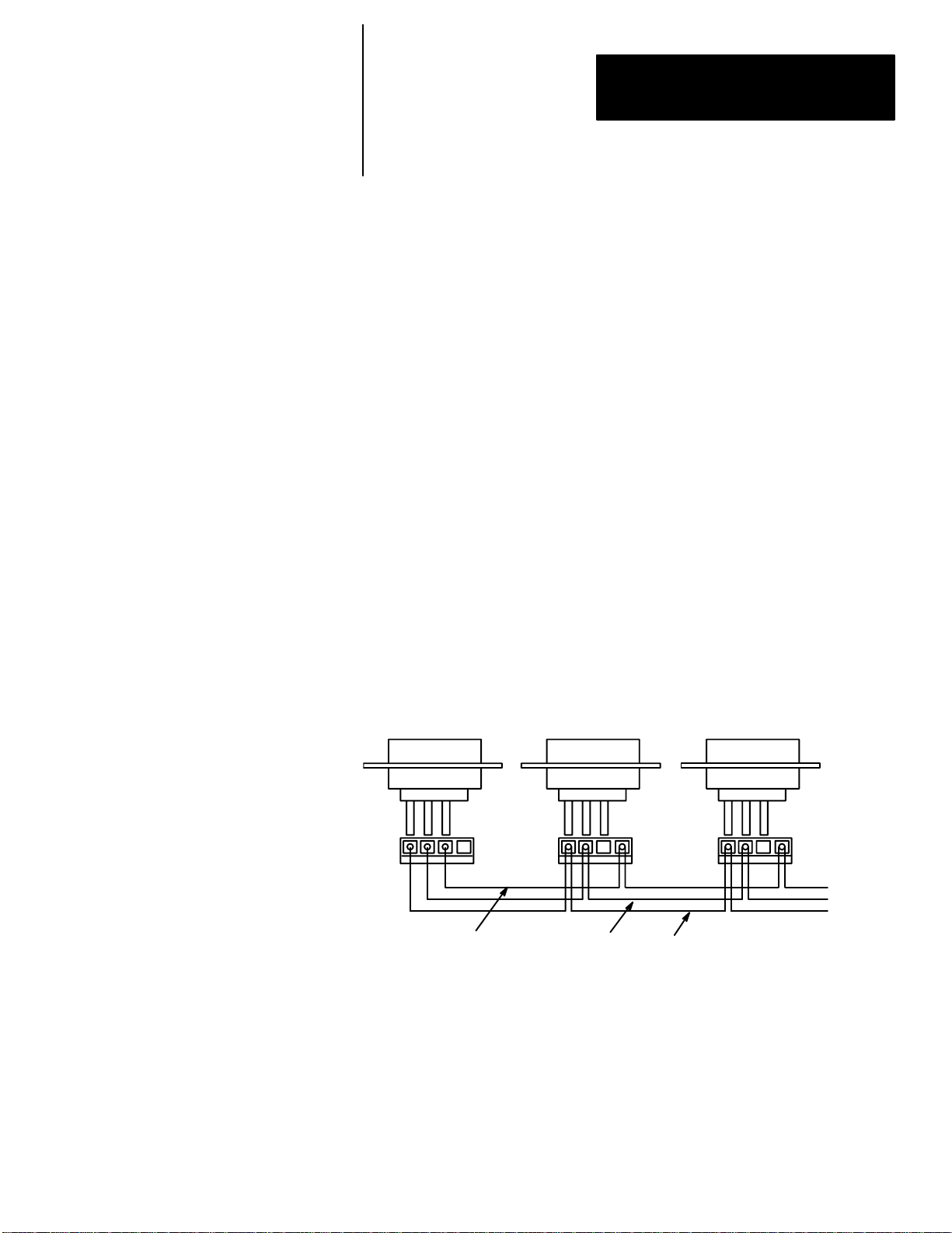
The Network Connector (Catalog No. 2708-NNC)
The Network Connector is made up of three elements. These are (1) the
plastic shroud or hood, (2) the DB-9 connector, and (3) the four screw
terminal block. The terminal block is wired to the back of the DB-9
connector. The black terminal wire is connected to pin 5 of the DB-9
connector and is the network (–) side of the RS-485 network. The red
terminal wire is connected to pin 4 of the DB-9 connector and is the network
(+) side of the RS-485 network. The blue terminal wire is the workstation’s
terminal’s chassis ground, and is connected to pin 8. The last terminal slot is
open and is not connected to the DB-9 connector.
2–3
Page 17
Chapter 2
Installing a Network
Simple Network (cont’d)
Figure 2.5
Network Connector (Catalog No. 2708-NNC)
Cabling a Network Using the Network Connector
Tools Needed — You will need a 3/32” flatblade screwdriver, and a pair of
wire strippers/cutter.
Cable Wire
The recommended cable is a Belden 8723. This cable has 2 pair of
conductors (4 wires) and a common drain wire. Although only one pair of
conductors is necessary for the network, it is desirable to have a back-up or
secondary pair in the event the primary pair has an open wire or some
unforseen malfunction occurs in the primary pair.
The primary cable pair consists of a Red and Black conductor which match
the color of the Network Connector leads. This primary pair will be used in
describing the cable connection.
Preparing the Wire
Check that the cable is cut off evenly. (There should be no wire hanging
beyond the cable insulation.) Remove about 3/4” of the insulation from the
end of the cable. Strip about 1/4” of insulation from the end of each wire.
Figure 2.6
Cable Connecting Length
1/4”
3/4”
2–4
Page 18
Chapter 2
Installing a Network
Simple Network (cont’d)
Installing the Connector
There are two types of connections using the Network Connector. These are
a Master connection and a Non-Master connection. These connections are
shown on Figure 2.7. The physical network connector is shown on Figure
2.4. An examination of both figures shows that there are four open sockets in
which to place three wires; the network plus (+), the network (–), and the
shield wires. In the Network Connector, the three wires connecting the
terminal block to the pins in the DB-9 connector are color coded. This is
consistent with all Network Connectors. It is advised the cable be
color-coded to match the Network Connector to avoid confusion.
Master Connection
The network (–) wire is placed in the connector socket for pin 5 of the
network connector. The network (+) wire is placed in the connector socket
for pin 4 of the network connector. The shield or drain wire is placed in the
connector socket for pin 8 and is the ground connection.
The shield wire is placed in the blue connector socket ONLY in a MASTER
or SUB-MASTER connection. This will effectively ground the network
cable at the MASTER only, and eliminate ground loop current problems.
Figure 2.7
Schematic of the RS-485 Network Using the Network Connector
Master Workstation
Shield or
Drain
Wire
Network Connector (Catalog No. 2708-NNC)
Normal Workstation
Net (+) Net (–)
Normal Workstation
To Other
Workstations
2–5
Page 19

Chapter 2
Installing a Network
Simple Network (cont’d)
NON-MASTER Connection
The following connections are NON-MASTER connections:
Normal
Concentrator
Alternate
Alternate Master
Alternate Sub-Master
All Non-Master workstations, with the exception of the last workstation in
the network, will have a cable going into and a cable coming out of the
network connector. This will cause two wires to be installed in each
connector socket. This is shown on Figure 2.8.
Figure 2.8
Two Wires in a Connector Socket
2–6
Twist the network (–) wires (black) together and place them in the black
connector socket and tighten the screw. Next, twist the network (+) wires
(red) together and place them in the red connector socket and tighten the
screw. The only cable leads left should be the drain or shield wires. Twist
these together and place them in the empty socket that has NO wire going to
the DB-9 connector. Tighten the screw and then examine all connections to
make sure they are secure and that no wires are touching any adjacent
connections to cause short circuits.
If the cable was cut and stripped according to instructions, it should be
straightforward to put the shroud on the network connector and complete the
assembly. When possible, it is advantageous to use the cable restraint device
in the connector to avoid pulling connections loose or breaking the wire.
Remember, cabling problems are the number one cause of problems in a
network.
Page 20

Chapter 2
Installing a Network
Step By Step Installation
It is recommended that at least a simple volt/ohm meter along with assorted
screwdrivers be acquired for installation.
Figure 2.9
The Completed Network Connector
Making a good cable installation is one of the keys to having a properly
working network. Cable installation must always alternate between
installation and inspection. The inspector’s job is to play devil’s advocate at
each phase. By inspecting in phases, you avoid having to do the entire job
over again when problems are found too late.
We recommend the following sequence:
1. Obtain tools, select connectors and cable type. Get a sample of the cable
so you can identify the colors.
2. Draw a MAP of where each workstation is to be placed in the building or
area. Trace a general path that the cable will follow in the physical
building. Make multiple copies of this diagram. One good way to do the
map is to get blueprints of the building and draw in the cables and
workstations. Make sure that you note the WORKSTATION NUMBER
which will be in each location, as well as the location of the Host
computer.
3. Make color keyed cable drawings showing which color wires go to the
pins of the connectors. We recommend you make multiple copies of this
drawing, and store one copy with the installation map.
4. Run the cable through the building. Always leave a few extra feet at each
workstation location so that there is room with which to work.
2–7
Page 21

Chapter 2
Installing a Network
Step By Step Installation
(cont’d)
5. Inspect the locations where the cable has been run, using a different
person than the installer. Make sure that the cable:
a. Is not run parallel to AC cables (BUILDING POWER) for more
than a few feet at any time. This will avoid induction of AC onto
your low voltage data network. Whenever the network cable must
cross AC power lines, they should cross perpendicular to each
other.
b. Is not allowed to rest on top of fluorescent lamps in the ceiling. The
ballasts from these lamps are worse than AC power lines.
c. Is never spliced in a manner that allows the cable to make a 3-way
junction. Network cables must be a bus. Only the Master
workstation and the last workstation can have a single network
cable going to them; all others will have two cables.
d. Is not located next to or run over large motors, building
transformers, or very large current areas, such as radiology labs.
e. Is not located where it is easily broken or shifted around.
Note: Make sure that the workstations are not next to building
transformers, or large electric motors. Induced voltage spikes can affect
the operation of the network.
6. Inspect visually every connector. It is recommended that a person, other
than the one who connected the wires, inspects the following:
a. Correct COLORS of wire have been connected.
b. Be sure that ALL of the strands of the conductor are properly
inserted into the connector. It is very easy to nick the wire when
stripping it. This results in the strands breaking.
c. Flex the wire at the connector a few times (this is not the time to
prove your strength, THEY CAN BE BROKEN) to see if the wire
has been badly nicked. It will break if this has occurred.
7. Inspect the pins for proper color in the proper hole.
8. Check continuity of the network cable by:
a. Temporarily short pins 4 and 5 of the MASTER workstation’s
network connector together. You can do this with a clip lead, or use
a female 9 pin solder type connector with pins 4 and 5 soldered
together. (You can get solder type connectors at local electrical
retailers.)
b. Set the voltmeter to the 100 OHM scale (or the nearest available
value).
2–8
Page 22

Chapter 2
Installing a Network
Step By Step Installation
(cont’d)
c. At the next workstation location, place the meter on pins 4 and 5.
You should have almost no resistance. A good rule of thumb is 1
ohm for every 25 feet of network cable. If there is 400 feet of cable
to the Master, then there should be no more than 16 ohms of
resistance.
d. Try each workstation in turn, checking to see that the resistance
does not change drastically. If the resistance is high, you may have
a poorly crimped pin, or a partial break in the cable itself. If the
resistance is infinite (completely open), then there is a break, or a
broken conductor.
e. By going from one station to the next, you can isolate what
segment of the cable has a problem.
f. When the entire cable has been checked, remove the jumper from
the Master’s connector.
9. Install the hoods on the connectors. Attach the connectors to the
workstations.
The Terminator Switch
After the network is installed, it is usually necessary to cancel out signal
reflections inherent in any cable layout. To do this, flip on the terminator
switch underneath the MASTER and SUBMASTER WORKSTATIONS
ONLY. The terminator switch is on the bottom of the workstation. The ON
position is toward the top of the workstation.
Figure 2.10
Terminator Switch
Note: The terminator switch should be OFF on all workstations except the
MASTER and SUBMASTER. If other terminator switches are on,
indeterminate network conditions will occur.
Communication Cables
The cables used to communicate from the Host computer to the Master or
from a Concentrator to a Sub-Master workstation use either RS-232 or
RS-422 signal standards. The connector pin-out diagrams for all of the
possible workstation configurations are shown in Appendix D.
2–9
Page 23

Chapter 2
Installing a Network
Testing the Network for Data Transmission
1. At the LAST workstation in the network, place the workstations into the
menu setup mode (see Appendix B).
a. Press the left arrow key (<) until the Diagnostic menu statement
appears in the display.
b. Press the ENTER key and then depress the left arrow key (<) until
RS-485 – BLK-Rx is shown on the display.
c. Press the ENTER key and the following should appear:
Rx = 00000 ERRS = 00
000
If the counters are not zero, press EXIT, then press ENTER, and they
should be set to zero.
d. Repeat steps a, b, and c for all workstations, except the Master
workstation.
2. At the Master workstation enter the Diagnostic menu and press the left
arrow key (<) until RS-485 – BLK-Tx is shown on the display.
a. Press ENTER and the display should show the following,
momentarily:
Tx = 00000 ERRS = 00
000
After the counters appear, the Tx counter will begin incrementing to
represent the number of blocks being transmitted over the network to all
workstations.
b. An observation of the display of the workstations placed in receive
will show the Rx counter changing accordingly as the transmitted
network blocks are received.
c. After a reasonable testing interval, press the EXIT key on the
Master workstation, thus suspending the network block test.
d. Examine each workstation to see that the Rx block count is the
same. It should be the same at all workstations (It is possible to be
off by one or two counts.) Also, inspect to see that ERRS count is
zero or less than three. Either a missing block count or high error
count indicates a bad network connection or a faulty workstation.
Exchanging the workstation will determine which is the case.
e. For additional confidence, perform step 1 at the Master workstation
location and step 2 at the last location. Step 1 may be repeated at all
other workstations. The changing of block transmission locations
verifies communications in the opposite direction.
f. Press EXIT three times on each workstation.
2–10
3. Always use retaining screws for all DB-9 connectors. Connect the RS-232
(or RS-422) cable to the host computer.
Page 24

Chapter 2
Installing a Network
Communication to the Host Computer
Connect the WORKSTATION COM1 Port to the Host computer using a
cable wired according to the pin-out diagrams shown in Appendix D. To
communicate to the Host computer, it is necessary to be able to make your
computer send and receive ASCII characters in an asynchronous
communication manner. If a personal computer is used, programs such as
PROCOMM
R
, and KERMIT are ideal for this purpose. Most
ASYNCHRONOUS TERMINAL EMULATION PROGRAMS will work.
The communication set-up parameters must be the same for both the
computer and the workstation terminal. Please see Appendix B, Menu
Trigger Keys, for the procedure to enter the workstation menu mode.
If the program is resident in the workstation, press the menu trigger keys
(Enter and Right Arrow simultaneously), disconnect power, then reconnect
power while holding down the Enter and Right Arrow keys simultanenously
to enter the workstation menu mode.
1. In the menu mode
1—Network
Menu
will appear.
Press ENTER; “Terminal Number” will appear.
Press 1, then ENTER; “Terminal Type” will appear.
Press < – until the terminal type changes to “Master”,
then press ENTER, then press EXIT.
2. Press the < –, until “2-Comm Port Menu” appears. Press ENTER;
“Comm Port Mode” will appear.
Press < – until the mode changes to “XON/XOFF”.
①
Press ENTER; and “Comm Baud Rate” will appear.
3. Press < – until the baud rate is the SAME AS THE BAUD RATE
SELECTED ON THE HOST COMPUTER. 9600 and 1200 are the most
②
common baud rates.
In some cases NO character will show up if the
baud rate is improperly set.
Press ENTER; “Comm Data Bits” will appear.
4. Press < – until the Data Bits are the same as the Host computer. This is
normally 7.
Press ENTER “Comm Parity” will appear.
① For testing the cable connections, use XON/XOFF. If you are using a data collection program such as Network
Manager Software (Catalog No. 2708-NNM), you may have to change this to “POLLED” before using such
programs.
② If the baud rate is incorrectly set, when your computer sends characters to the workstation, unpredictable
characters will show up on the display when you are in “COMM RECEIVE TEST” mode. In some cases NO
character will show up if the baud rate is improperly set.
2–11
Page 25

Chapter 2
Installing a Network
5. Press < – until the parity is the SAME AS THE PARITY SETTING ON
THE HOST COMPUTER. A selection of “EVEN” is commonly used.
③
Press ENTER; “Comm Stop Bits” will appear.
6. Press < – until “One” appears.
④
Press ENTER; “Comm CRLF” will appear.
7. Press < – until “ENABLED” appears.
⑤
Press ENTER; “Comm Echo” will appear.
8. Press < – until “ENABLED” appears.
⑥
Press EXIT; “1-Network Menu” will appear.
9. Press OUT; “Diagnostics” will appear.
Press ENTER; Press < – until “Comm Rx Test” appears.
Press ENTER;
10. The following should appear on the two line display:
DTR: ON CD: ON
Pressing the number 1 and 2 will turn DTR ON and OFF.
⑦
11. Start the communication program on the Host computer. If the program is
an asynchronous terminal emulator program, then characters that are
typed on the computer are sent directly over the communication line.
These characters should appear on the top line of the workstation
display.
⑧
2–12
12. Press EXIT; “Comm Rx Test” will appear.
Press OUT; “Comm Tx Test” will appear.
Press ENTER; The top line will be blank and the second line will show:
DTR: ON CD: ON
The Host computer should be receiving a continuous transmission of
③ If the parity is set incorrectly, the workstation will still RECEIVE characters properly. Your Host computer may not
receive correctly, if at all.
④ If the baud rate is incorrectly set, when your computer sends characters to the workstation, unpredictable
characters will show up on the display when you are in “COMM RECEIVE TEST” mode. In some cases NO
character will show up if the baud rate is improperly set.
⑤ If you find that your computer is receiving double spaced lines from the workstation, then set CRLF to
DISABLED. Also disable when using Network Manager Software (Catalog No. 2708-NNM) or similar software.
⑥ If you find that when you are using your workstation program, you see two characters for each one you type
(such as DDIISSPPLLAAYY//HHEELLOO//) then set Com Echo to DISABLED. Note that when using a data
collection program (such as Network Manager Software (Catalog No. 2708-NNM) you will also DISABLE this
option.
⑦ Your computer may be unwilling to transmit characters unless these RS-232 lines are in the proper state. If you
are having trouble communicating, check your cable diagram against the specifications for your computer’s
RS-232 port. Additionially, the workstation requires CD to be high (or on) for communications.
⑧ Random characters on your computer or the workstation display indicate the baud rate is wrong. If about half of
the characters are wrong or missing, the parity is set incorrectly. If nothing at all happens, the cable is wrong or
something is broken.
Page 26

Chapter 2
Installing a Network
“The quick brown fox jumped over the lazy dog”⑨ type of messages.
Communications can receive at rates that are faster than any terminal
emulation program due to the use of POLLED mode as the COMM
PORT MODE.
13. Press EXIT, three times
14. The AUX port (labeled COM2 on the back of the workstation) can be set
up and checked out in the same manner as the primary COM1 port. The
AUX port, however, is strictly a data transfer port operating with
XON/XOFF flow control. It has transmit, receive, and signal ground
lines. There are no modem control lines on this port.
The installation of the workstation in a simple network is now complete.
Complex Network
Description of Large or Complex Network
Installing a large or complex network of workstations involves connecting
together several smaller networks.
The network which connects all of the smaller or sub-networks together is
called the “backbone” network. Each sub-network is referred to as a
“tributary” network. Up to 31 tributary networks may be attached to the
backbone to form a very large network. Each tributary, in turn, may contain
up to 32 workstations. A maximum of 1024 workstations may be connected
in this fashion. Once the layout of such a network has been determined,
cabling proceeds in the same manner as cabling for a single or backbone
network. Both tributary and backbone networks are wired as previously
described.
The workstation which is attached to the Host is configured as the “Master”.
Each workstation on the backbone network that connects to a tributary
network is configured as “Concentrator”. The workstation on the tributary
which attaches to the Concentrator is configured as the “Sub-Master”.
⑨ After a few seconds or minutes of receiving these messages, your computer starts displaying wrong characters or
only parts of messages, then your computer (or the communications program) is unable to accept records at the
rate they are being sent by the workstation. Try a lower baud rate on your Host and the workstation until you can
receive successfully as quickly as the data is sent. Note that some programs such as Network Manager Software
(Catalog No. 2708-NNM) can receive at rates that are faster than any terminal emulation program due to the use
of POLLED mode as the COMM PORT MODE.
2–13
Page 27

Chapter 2
Installing a Network
Figure 2.11
Large Network Configuration
Host M—W—C—W—C—W—C—W—W—C—C—W
W
|
W
|
W
|
S
|
|
S
|
W
|
W
|
W
|
W
|
S
|
W
|
W
|
W
W
|
W
|
S
|
|
S
|
W
|
W
2–14
Key:
W Workstation
S Submaster
C Concentrator
M Master
Indicates RS-232 or RS-422 connection
Indicates RS-485 backbone
Indicates a tributary
All of the workstations, including Masters, Concentrators and Submasters,
are standard workstations which have been configured for their individual
roles in the network. A configuration parameter is changed to allow any
workstation to adopt a new role in the network. Each workstation is capable
of operating in both a data collection and a data communications mode.
A workstation which is being used as a Master, Concentrator, or
Submaster can perform data collection functions even while serving in
the communication network.
Alternate Communication Links
When installing large networks, you may consider redundant communication
links in order to protect against Host or Master workstation failures. This
involves establishing certain workstations as “Alternate Sub-Masters”.
Configuring a large network with Alternate Masters will allow the alternate
workstation to take over communication operations if the designated Master
becomes inoperable or is removed from the network. An Alternate Host
provides full redundancy for collection in the event of a Host failure.
Page 28

Chapter 2
Installing a Network
Figure 2.12
Large Network Configuration with Alternate Masters
Host 1 M—A—C—C—C—W—C—C—W—C—C—C
Host 2
S
AS
W
|
|
S
|
|
W
|
|
W
|
W
W
|
W
|
AS
S
W
|
W
|
|
|
S
|
|
S
|
AS
|
W
Key:
W Workstation
S Submaster
M Master
C Concentrator
A Alternate Master
AS Alternate Submaster
Indicates RS-232 or RS-422 connection
Indicates RS-485 backbone
Indicates a tributary
An Alternate Submaster will allow the communication operations to continue
through a secondary Concentrator if the primary Concentrator becomes
inoperable or is removed from the network.
Networks Over Telecommunications Lines
It is possible to configure a workstation network which spans multiple
buildings, outposts, or sub-stations located at remote sites. Switched or
leased telephone lines can be used with asynchronous modems to provide
communication links for such a network.
Asynchronous short-haul modems may be used to extend the normal RS-232
communication distance from 100 feet to as much as several miles. To use
modems for communications between a Concentrator and Submaster the
workstations MUST have an RS-232 communication port (Workstation
Catalog No. 2708-DH5B2L). A modem cable must be correctly connected to
TXD, RXD, RTS, CTS, DSR, DTR, and GROUND signals (see Appendix
D). The COMM BAUD RATE parameter must be changed to the same baud
rate as the modem.
2–15
Page 29
Chapter 2
Installing a Network
As soon as the modems establish communication between themselves, the
remote system will be ready for use.
Extension of a network across telephone lines consists of placing a modem
on one side of the line to connect with the Concentrator, and placing another
modem on the other side to connect with the Submaster.
Figure 2.13
Extending Network Across Common Carrier
Backbone
Network
W
|
M
|
W
|
W
|
C
|
W
|
W
Key:
W Workstation
S Submaster
C Concentrator
M Master
Figure 2.14
Use of the Gateway Option
Backbone
Network
W
|
W
|
G
|
W
|
W
HOST
modem modem
Telco
Indicates RS-232 connect
Indicates telephone line
Indicates RS-485 backbone
modem modem
Telco
Tributary
Network
W
|
W
|
W
|
S
|
W
Tributary
Network
W
|
S
|
W
2–16
Key:
W Workstation
S Submaster
C Concentrator
M Master
G Gateway
Indicates RS-232 connect
Indicates telephone line
Indicates RS-485 backbone
Page 30

Chapter
Chapter Objectives
A–B
3
Barcode Connection
The barcode connector on the back of the workstation is a 9 pin DB-9
connector for the bar code scanner.
Connection
The pin-out for the BARCODE connector on the back of the workstation is
shown on Figure 3.1.
Figure 3.1
BARCODE Connector
54321
9876
Pin Number Function
1 Start of Scan. . . . . . . . . . . . . . .
2 Data. . . . . . . . . . . . . . .
3 LED light. . . . . . . . . . . . . . .
4 NOT CONNECTED. . . . . . . . . . . . . . .
5 Trigger. . . . . . . . . . . . . . .
6 Laser synchronization. . . . . . . . . . . . . . .
7 GROUND. . . . . . . . . . . . . . .
8 GROUND. . . . . . . . . . . . . . .
9 Power (+5V). . . . . . . . . . . . . . .
Allen-Bradley offers the following barcode scanners for use with the
workstation:
— Catalog Number 2755-G3 or -G6 Hand-Held Scanner
— Catalog Number 2755-W1, -W2, or -W5 Wand
— Catalog Number 2755-B1 or -B2 Slot Scanner
3–1
Page 31

Chapter
Introduction
A–B
4
Status Displays
The status display provides visible and easily available information
concerning the state of the 2708-DH5B2L or -DH5B4L Attended
Workstation. The workstation reports its operational status through ten
informational displays on the front panel LCD Display. The status displays
are automatically shown when the workstation is powered up unless a
BASIC program is running. Each of the status displays is assigned a number
from 0 to 9. To see status display 1, press the “1” key. When any number is
entered, the workstation will present the status display associated with that
number. The ten displays are:
1. Network Status.
2. Reserved Status.
3. Time Status.
4. System Reset Status.
5. Network Que Status.
6. Workstation Memory Status.
7. Program Load Status.
8. Program Run Status.
9. Application Status.
0. Summary Status.
On the workstation’s 2 x 40 display, two separate status displays will be
shown.
Figure 4.1
Example Status Display
N . . . . . . NN . 01–01 <0 2> NETWORK 2
01234556789 MASTR
4–1
Page 32

Chapter 4
Status Displays
Introduction (cont’d)
With the display, the workstation can show two status displays at the same
time. In Figure 4.1, the summary status display is on the left hand side along
with the reserved status on the right hand side. The ‘< 0’(in Figure 4.1) is
associated with the summary status (left hand side), and signifies that the
summary status is status display number zero. The ‘2>’ tells us that the right
hand display is status display number 2.
On the display, as the user selects a new status display, the new status screen
will be displayed on the left hand side, and the display on the right hand side
will be replaced by the one from the left hand side.
Invoking Status Display – Status displays are visible under these
circumstances:
1. After power-up for 15 seconds.
2. When the workstation has a non-zero terminal number, but is without an
A-B VBASIC program.
3. When the A-B VBASIC program terminates.
4. When manually invoked during a power up. This method will present the
status display for 15 seconds after the last keystroke. The A-B VBASIC
program, if loaded, will resume execution after this 15 second status
display.
Summary Status Display (Status Display 0)
The Status Display 0 summarizes the status of the other nine status displays.
The numbers 0-9 on the lower line represent the ten status displays. The
information above each number refers to the number under it, i.e. the ’.’ over
the 3 refers to the status display 3 – the time display.
Figure 4.2
Summary Status Display
N . . . . . . NN . 01–01
01234556789 MASTR
4–2
Page 33

Summary Status Display
(Status Display 0) (cont’d)
Chapter 4
Status Displays
Display No. / Name Code Description
1 Network Status.
2
3
4 System Reset.
5 Network Queue.
6 Workstation Memory .
7 Program Load.
8 Program Run.
9 Application.
0 Summary
Reserved Status.
Time Status.
Online
O
S
•
T
•
R
•
O
•
F
•
N
L
•
E
N
•
Offline
Standalone
Always a period
Time is set
Time is not set
No serious errors
Serious error occurred
Online
Offline
Memory remains
Out of memory
Program loaded
Never loaded
Loading error
No errors
Run error
Never ran
Always a period
To view one of the other nine status displays, simply enter the number key
associated with the status display desired while viewing status.
The ‘01-01’ is the workstation number. The first number is the Master
number (01), the second number is the individual workstation number (01).
In this example the Master number and the workstation number are the same.
In the case of Master number 06 and workstation number 24 the total
workstation I.D. number would be ‘06-24’.
4–3
Page 34

Chapter 4
Status Displays
Network Status (Status Display 1)
The Network Status display shows information about the network. The
information is updated many times a second, to reflect the status as it
changes.
The information displayed appears in the following form:
Figure 4.3
Network Status, Display 1
mm-tt Ready a
mode [type] a
where, moving from left to right on the top line:
mm is the Master ID or Submaster attached to the workstation. If the
workstation is not attached to a network string, no Master ID will
be present.
tt is the workstation or station ID number.
Ready indicates that the application program is capable of performing a
SEND operation. Alternately,
4–4
Full Indicates that there is no memory remaining in which to save data.
a represents the current polling address. The character which
represents the polling address will be a space, while the unit has the
factory configuration and is offline. If the workstation is online and
waiting for a poll, a question mark will appear in this position.
Moving from left to right, the bottom line meanings are:
mode ONLINE The workstation will send records to its Master.
OFFLINE The workstation will not send records.
TERMINAL The workstation is in standalone mode, and sends
each keystroke.
type The role the workstation plays in the network:
[N] Normal
[M[ Master
[A] Alternate Master
[C] Concentrator
[SM] Submaster
[AM] Alternate Submaster
[G] Gateway
Page 35

Chapter 4
Status Displays
Reserved Status (Status Display 2)
Time Status (Status Display 3)
This display (Figure 4.4) currently has no function. Allen-Bradley has
reserved this menu for future enhancements.
Figure 4.4
Reserved Status, Display 2
NETWORK 2
This display shows the time and date.
Figure 4.5
Time Status, Display 3
2:01:25 PM
MON MAY 8, 1990
To change the format of the time and data, simply choose the option CLOCK
MODE on the system menu (menu 3). Refer to Appendix I for a description
of the CLOCK MODE options.
System Reset Status (Status Display 4)
Serious errors encountered by a workstation are known as “system resets”.
To try and correct a problem the workstation will reset itself and in the
process will attempt to identify the error. The error is then logged, and the
number of system resets is incremented.
Figure 4.6
System Reset Status, Display 4
EC ##
AThhmmssnnyymmdd
The EC in Figure 4.6 represents the Error Code. The ## represents the
number of serious errors. The lower lines gives you “at time and date”.
4–5
Page 36

Chapter 4
Status Displays
System Reset Status
(Status Display 4) (cont’d)
A – Error Codes
1 Undetermined reason for failure
8, 10 These error codes could be the result of excessive power
fluctuations or a sign that the workstation is not functioning
properly because of a hardware problem. Technically, the error is a
result of the micro-processor vectoring to the restart vectors. If the
problem continues, contact your A-B representative.
82 Stack overflow
83 Bad transaction memory structure
84 Illegal interrupt
85 8048-64180 mismatch
86 Bad byte count from extended RAM
87 String from network not properly terminated
88 Invalid block address
89 Out of memory for files
Network Queue Status (Status Display 5)
4–6
This display presents the status of the data queues which link the A-B
VBASIC program to the network.
Figure 4.7
Network Queue Status, Display 5
MODE R C
H L RS S
The top line contains:
Mode [OFF] Offline, the workstation is unable to communicate with the
Host.
[ON] Online, the workstation has established communications with
the Host.
R Records From Host – Records from Host applies to the number of
data records which have arrived from the Host. This number does
not include network commands, only data destined for the A-B
VBASIC program.
Page 37

Chapter 4
Status Displays
Network Que Status
(Status Display 5) (cont’d)
C Count Of Records Lost From Host – This count is incremented
whenever a data record arrives from the network, before the
previous one was read by the A-B VBASIC program.
The lower line contains:
H Host Output Blocked Flag.
Data collected by the application is not being forwarded to the
network, because the Host device is not currently OPEN by an A-B
VBASIC program. Unless some action is taken to OPEN “Host”,
this data will be stranded. The condition can be cleared by an:
OPEN “Host”
KILL “Host”
KILL “QUE”
L Lost Data Flag
Data has been lost. This could be because the Host sent a record
and the workstation was not ready to receive it, or the Host is
sending faster than the workstation can process the data.
RC Record Count From Network – This is a count of the records which
have been transmitted to the Host from the A-B VBASIC program.
S Size Of Host Queue – This is the number of bytes currently in the
que for transmission to the Host. Data in this queue can be
prevented from going to the Host by:
1. A Host computer which has stopped polling (when the Master is in polled
mode).
2. A Host computer which has issued a XOFF, (any mode).
3. The device Host being closed. This condition is associated with the Host
Output Blocked Flag.
4. The workstation being offline.
4–7
Page 38

Chapter 4
Status Displays
Workstation Memory Status (Status Display 6)
This display presents information that describes the utilization of the
workstation’s RAM.
Figure 4.8
Workstation Memory Status, Display 6
RAM PGMEM LPMEM
BFUSE BLEFT
The top line contains:
RAM Total RAM Memory – Displays the total number of K bytes of
RAM installed.
PGMEM Bytes Remaining For Program Use – This value shows the
amount of RAM available for an A-B VBASIC program. The
value is decreased from its factory default setting by the use of
memory for:
1. Program pseudo-code (i.e. “logic”)
2. Program variables
3. Program pseudo-stack (for procedure returns, etc.)
This value is reset to its factory default when the first record of an A-B
VBASIC program is received (the “>, AA record”). It is decremented as the
program arrives and as it runs. Thus, this value reflects the difference
between the factory default and the maximum used by the current application
(A-B VBASIC program).
LPMEM Least Used Program Memory – This value represents the
program’s peak memory utilization. A value of zero means that at
some point, the program memory was full.
The lower line contains:
BFUSE Bytes For File Usage – This value shows the amount of RAM
available for use in A-B VBASIC files.
If this value ever reaches zero, the effect will be quite serious,
unless the A-B VBASIC program detects this condition.
BLEFT Bytes Remaining For File Use – The amount of RAM available
for file use that has never been used by the current application.
4–8
Page 39

Chapter 4
Status Displays
Program Load Status (Status Display 7)
This display shows the progress of the loading operation of the A-B VBASIC
program on the top line and the date/time of the loading operation on the
lower line.
Figure 4.9
Program Load Status, Display 7
LOAD STATUS MSG
AT hhmmss yymmdd
Program Load Messages that could appear on the top line are:
Never loaded This message appears from the time the workstation
is set to factory defaults until the arrival of a
program record.
Loading Line: xx This message is shown as each program record is
received. It should take only a few moments at most
to load a program. If this line is not being updated
every few seconds, the download operation has been
interrupted, possibly by a communications protocol
error from the Host computer.
Loaded <filename> This message indicates that the A-B VBASIC
program was loaded without error and started. The
PC program name is shown. Note: This does not
imply that the program loaded is currently running.
For workstation run status, check status display
eight.
Load Sequence xx – This message indicates that at least one of the
records of the program was received in the wrong
order. The ‘xx’ indicates the expected record.
Length Counters! – This message indicates that the counters holding the
size of the program’s pseudo-code and array
descriptions do not equal the total program length
counter.
Load Length! – This message says the amount of pseudo-code
received does not equal the number supplied in the
total length count.
Program Checksum – This message says the checksum of the pseudo-code
does not equal the value expected.
4–9
Page 40

Chapter 4
Status Displays
Program Load Status
(Status Display 7) (cont’d)
Program Run Status (Status Display 8)
Interpreter Vers – Unlike the previous errors, this error is probably due
to an incompatibility between the interpreter
firmware in the workstation and the version of the
LXB cross-compiler that made the program file.
Consult technical documentation or Allen-Bradley
representative to determine whether the compiler
employed is correct for the workstation which is
being downloaded.
The lower line tells you at what time and date the error occurred.
This display shows the running status of the A-B VBASIC program.
Figure 4.10
Program Run Status, Display 8
PROGRAM STATUS
####: yymmddhhmm
Program run status messages that could appear on the top line are:
Argument count POP-LOAD wrong tag*
Argument count mismatch Pseudo-PC*
Big file number Pseudo-stack underflow
Copy record leng RETURN no GOSUB
Divide by zero Seek < 1
Double overflow Seek past EOF
End of SYSTEM Stack tag*
File memory STORE stack tag mismatch*
File name overflow String overflow
File not open String/Network type mismatch
File number busy Subscript range
Formal Parameter Swap length
Format type mismatch SWAP_STR IV item*
Get needs RANDOM Tag required popping stack*
New Progrm Load Type count mismatch*
No field format Type for PRINT&WRITE*
Not Data item Type mis: whole
Not a NORMAL terminal type Type mismatch
Not string item*
ON jump out-of-range
Operator Abort
Open file limit
The offset in the pseudo code causing the message appears as ####: on the
lower line with the date and time.
4–10
*
Indicates a Bad Error Message (problem in the application program).
Page 41

Chapter 4
Status Displays
Application Status (Status Display 9)
This display is available for workstation application use. It is under the
control of the A-B VBASIC program currently running. It’s contents are set
via the STAT device (see I/O supplement for details). Unless changed, the
display reads as follows.
Figure 4.11
Application Status, Display 9
Application
Status
4–11
Page 42

Chapter
Introduction
Using Menus via Workstation Keypad
A–B
5
Configuration Menus
The workstation uses menus to make configuration parameters accessible and
easy to change. They were designed to be entered, changed and exited by
pushing various keys on the keypad. It is also possible to access the menus
through the communications port using host commands. See section
“Menu 2: Comm Port Menu Parameters”.
In order to access the menus, press the menu trigger keys (Enter and Right
Arrow simultaneously). If a program is loaded, the trigger keys must be held
down while power is removed and then reapplied.
The first menu is the Network Menu and it looks like the display in Figure
5.1.
Figure 5.1
Network Menu
1–Network Menu
< for next menu
When the IN key is pressed, it will allow you to scan the six major menus,
one at a time. They are:
1. Network Menu
2. Comm Port Menu
3. System Menu
4. Bar Code Menu
5. Read Only Menu
6. Diagnostics Menu
From the Diagnostics Menu, pressing <IN> one more time will cause the
Network Menu to reappear. By pressing <OUT> you can scan backwards or
you can select the desired menu by pressing the appropriate menu number.
For example, if the Comm Port Menu is showing on the display, you can get
to the Diagnostics Menu simply by pressing the <6> key. The Diagnostics
Menu will now appear on the display.
5–1
Page 43

Chapter 5
Configuration Menus
Using Menus via
Workstation Keypad (cont’d)
Sub-Menus
After you have selected the appropriate menu item, you can now examine the
sub-menu by pressing <ENTER>.
With the exception of the Diagnostic Menu (which is discussed later), you
can scan through the list of parameters by pressing <ENTER>, and scan
backwards by pressing <CLEAR>. The parameter which appears on the
display is the one which is selected.
Once a parameter is selected, it may be changed. The settings or options
suitable for that parameter can be examined/changed by pressing
<LEFT ARROW>. For some parameters, this is a numeric item which
requires that you enter a value in order to modify it. Once the parameter
has been changed, you must press <ENTER> for the parameter to be
accepted. If you press <EXIT> or <CLEAR> without having pressed
<ENTER>, you selection will be ignored.
Note: Once you have entered the diagnostics menu (by pressing <ENTER>
from the 6-Diagnostics menu) use <LEFT ARROW> to move through and
select the diagnostic you want to execute. Press <ENTER> to start the
diagnostic. Most diagnostics can be stopped by pressing <EXIT>. Pressing
<EXIT> from any of the parameters will return the unit to the Network Menu
(Figure 5.1).
Exiting Network Menu
Pressing <EXIT> from the Network Menu will exit the menus completely.
First, “Final Exit” (Figure 5.2) will briefly appear on the display, to be
replaced either by the status display, or in the case where a program has been
already placed into the workstation, program run will begin.
Figure 5.2
Final Exit Menu
Final Exit.
5–2
Page 44

Chapter 5
Configuration Menus
Using Menus from the Comm Port
After you have attached the cable from the COM1 or COM2 port on a Master
workstation to the appropriate port on your PC or Host, you must transmit a
control character sequence from the communication port menu (see section
titled “Menu 2: Comm Port Menu Parameters”). This is typically done by
holding down the Control (Ctrl) key and pressing the appropriate letter key
(T, C, O, or N) at the same time.
Note: The factory default configuration of the COM1 and COM2 ports is
9600 baud, 7 data bits, EVEN parity and 1 stop bit. The workstation will also
ECHO each character it receives.
The following should appear on your PC:
Figure 5.3
Menu Mode
––––Menu Mode––––
Use Backspace to select
Use Return for next item
Use Control-Z to exit
1–Network Menu
If the workstation does not show the text in Figure 5.3, then you should
check to make sure:
1. The cabling is correct.
2. Your workstation baud rate matches that of the host.
3. The workstation has not been configured as a Concentrator, Submaster or
Alternate Submaster.
4. A control character, such as Control-T, is selected to enter the menus from
the comm port. Check the Comm Menu Character in the comm port
menu.
The <BACKSPACE> and the <SPACE> key will allow you to select one of
the following menus:
1–Network Menu 2–Comm Port Menu
3–System Menu 4–Bar Code Menu
5–Read Only Menu 6–Diagnostics
When you have selected the menu you want, press the <ENTER> key on
your workstation. Each time you press <ENTER>, the display will skip down
to another parameter in the menu. Holding down the <CTRL> and pressing
<Z> (referred to as < ^Z>) will exit from the menu back to the 1–Network
menu. Exiting from the Network menu with the < ^Z> will display:
Final Exit.
The workstation will then continue its normal operation.
5–3
Page 45

Chapter 5
Configuration Menus
Using Menus from
the Comm Port (cont’d)
Menu 1: Network
Menu Paramters
Notice that the selection of a parameter can be managed by scanning through
the parameters using <backspace> or <space>. Also, the number or letter of
the parameter you wish to invoke can be entered directly. In the case of the
Diagnostics, this can be particularly helpful due to the large number of
Diagnostics available.
Pressing <LEFT ARROW> will back through the parameters.
Note: To enable a parameter, you must press <ENTER> in order for your
selection to actually take place. Pressing < ^Z> or <DELETE> will cause
your selection to be ignored.
The following is a description of those parameters accessed by pressing
<ENTER> when 1–Network Menu is showing on the display.
Workstation
Setting terminal to zero (0) turns the workstation into a dumb terminal
(“standalone mode”). Normally a workstation will be configured as number
1-99. The terminal number (I.D. number) is 0 only when the workstation is
used in standalone mode. A value between 1 and 99 must be used for the
workstation to operate on a network.
Note: The selected workstation number must be different from the other
terminals on the network. Two workstations cannot have the same terminal
number.
Workstation Type
The six possible workstation types are:
Normal Standard Workstation
Master Communicates with Host via the Com1 port
Alternate Backup for the Master
Concentrator Connects Submaster to backbone network
Submaster Connects tributary to Concentrator
Alternate Submaster Backup for Submaster
Gateway Master/Concentrator
Lower Poll Addr (1 - 99) – This value is set on each Concentrator/-
Master workstation and specifies the lowest
unit number that the Concentrator or Master
should attempt to locate. It is used to
expedite bringing units online in small
network environments.
5–4
Host Port (COM or AUX) Select which port will communicate with the
host device.
Page 46

Chapter 5
Configuration Menus
Menu 1: Network
Menu Paramters (cont’d)
Upper Poll Addr (1 - 99) – This value is set on each Concentrator/-
Master unit and specifies the highest unit
number plus 1, that the Master or
Concentrator should attempt to locate when
bringing units online. It is used to expedite
accommodation of workstations coming
online in a small network environment.
Offline Cycle (normally 40) – This value is set on each Concentrator/-
Master workstation and gives the number of
online unit polls which will be performed
before an attempt is made to find an offline
workstation. Larger values will initiate
fewer polls for offline workstations.
Max Net Retries (1 - 999) – This value is set on each Concentrator/-
Master workstation and is the number of
times that the Concentrator/Master will retry
a failed poll before designating the
workstation offline.
Comm Mode – The following communication protocols are
selectable:
XON/XOFF
DSR
Polled
Request
Menu 2: Comm Port
Menu Parameters
The following is a description of those parameters accessed by pressing
<ENTER> when 2–Comm Port Menu is showing on the display.
Comm Port Mode
The four parameters available are:
The data collection software you use on your Host will determine which
comm port mode to use. (If you are using the Network Manager Software
package (Catalog No. 2708-NNM), set the comm port mode to POLLED.)
XON/XOFF Use Control-Q (XON) and Control-S (XOFF).
In this mode, the Master sends the data records to the Host as
they are collected. Records are sent from the workstation
even if there is a problem with the Host, or no Host exists.
Note: If the host is not ready to receive the data, the data
will be lost.
DSR Lower DSR to stop transmissions.
5–5
Page 47

Chapter 5
Configuration Menus
Polled The workstation transmits only when polled. However, if
DSR or Polled mode are selected, XON/XOFF will also be
honored by the workstation.
Request This mode does error checking and retransmission of all data
blocks. It is intended for electrically noisy environments.
Comm Baud Rate
The following baud rates are available:
19200 1200
9600 600
4800 300
2400 150
75
Comm Data Bits
The parameters are 7 to 8.
Comm Parity
Your choice of parities for 7 data bits are:
Even
Odd
None
Zero
Mark
Your choice of parities for 8 data bits are:
Even
Odd
None
Comm Stop Bits – Parameters available are:
One
Two
One and a half
Comm CRLF Parameters are Enabled or Disabled. When enabled, the
workstation will send a line-feed after each carriage
return that it transmits.
5–6
Comm Echo The choices are Enabled or Disabled. When enabled, the
workstation will echo each character it receives from the
comm line back to the communications line. This must
be disabled when communicating with most Host
computers.
Sync Count When 0, asynchronous communication is enabled on the
COM1 port. This should always be left at 0 (zero).
Page 48

Chapter 5
Configuration Menus
Aux Baud Rate for COM2 – The following baud rates are available:
38400 1200
19200 600
9600 300
4800 150
2400 75
Aux Parity For COM2 – Parity choices are:
Even
Odd
None
Zero
Mark
Aux CRLF For COM2 – Parameter choices are:
Enable
Disable
Aux Echo For COM2 – Parameter choices are:
Enable
Disable
Comm Menu char – Parameter choices for enabling menu configuration
from a host computer are:
^T
^C
^O
^N
NONE [Default]
This parameter specifies the character that is used from the comm ports to
enter the menu mode. NONE is the default. If the selected character conflicts
with the data transmission between the Host and the Master workstation, then
it may be necessary to select another character to be used to signal the
workstation to enter the menus.
When the NONE option is selected, it is not possible to enter the menus
from the comm ports, nor is it possible to reboot the workstation with
the ^R character.
5–7
Page 49

Chapter 5
Configuration Menus
Menu 3: System Menu Parameters
Time (hhmmss) Current time – This is one method of setting time in the
workstation. Notice that the time shown is the time the menu was entered.
Date (yymmddw) Current date – This is one method of setting the date and
day of week in the workstation. The date must be entered in year, month, and
date order. The “w” represents the day of the week. (Sunday = 1 through
Saturday = 7).
Menu Password 0-9999 – When this is non-zero, the workstation user will
be required to enter this value before access to the menus is allowed.
Note: For added security, the user will be shown prompts for a 5–digit
password, even though only four digits configured are entered.
Clock Mode 1 - 35 (normally 7) – This is a value which contrtols the format
of the time on status displays. This does not affect the BASIC “Time$”
variable. See Appendix I for the full list of formats, and examples of each.
File Block Size – This value controls the size of the blocks which are
allocated for file usage
①
. Choices are:
256
512
1K
2K
4K
Menu 4: Bar Code Menu Parameters
5–8
The following is a description of those parameters accessed by pressing
<ENTER> when the 4–Bar Code Menu is on the display.
Code 3 of 9 Enabled/Disabled. . . . . . . . .
The workstation will auto-discriminate between codes that are enabled. In
order for the workstation to even attempt to read a code, it must first be
enabled. By default, only Code 3 of 9 is enabled.
Code 3 of 9 Check Digits Disabled/Enabled
Enables check digit verification of all codes read using Code 3 of 9.
①
See the chapter on RAM files in the A-B VBASIC Program Development Manual.
Page 50

Chapter 5
Configuration Menus
Menu 4: Bar Code
Menu Parameters (cont’d)
Code 3 of 9 Mode
ASCII Full ASCII character set.. . . . . . . . . . . . .
Normal Only Does not allow +$ to switch mode.. . . . . . . .
ASCII Only Does not allow -$ to switch mode.. . . . . . . . .
Code I 2-of -5 Disabled/Enabled. . . . . . .
Used to enable Interleaved 2 of 5.
I 2-of-5 Check Dgts Enabled/Disabled. .
I 2-of-5 Length
This command enables and disables the I 2-of-5 label length checking. There
are three types of label length checking:
n = 0
I 2-of-5 symbols can be of any (even) length between 4 and 32 digits,
inclusive.
n > = 3 and n < = 32
Only symbols of length n will be read. If an odd value of ‘n’ is specified, it
will be incremented to the next even integer since I 2-of-5 symbols must
have an even number of digits.
n = 33
Then the symbols can be either 6 or 14 digits long.
Codabar Disabled/Enabled. . . . . . . . . . .
Used to enable Codabar.
Code 128 Disabled/Enabled. . . . . . . . . .
Used to enable Code 128.
UPC UPC/EAN/JAN, UPC only, or Disabled. . . . . . . . . . . . . .
Used to enable UPC, European and Japanese Codes.
UPC Supplement None, 2-digit only, 5-digit only, or 2 and 5. . .
Enables reading of the 2 or 5 digit supplement to the standard UPC code.
Bar Header None or STX. . . . . . . .
This selects a header to be sent in front of bar codes which are SENT IN
STANDALONE MODE ONLY. By default, no header is sent.
Bar Trailer CR, NONE, ETX, or TAB. . . . . . . . .
This selects a trailer to be placed on the end of barcodes which are sent in
STANDALONE MODE ONLY. By default a carriage return is sent.
Bar Echo Enabled/Disabled. . . . . . . . . .
This enables the echo of bar codes to the display in STANDALONE MODE
ONLY.
5–9
Page 51

Chapter 5
Configuration Menus
Menu 5: Read Only Menu
Menu 6: Diagnostics Menu Parameters
The Read Only Menu displays the following information:
1–ROM configuration, version and date
2–RAM side
3–Serial Number
4–Program Load Status – i.e. never loaded or never started
The diagnostics provided in the firmware of the workstation allow testing of
the internal hardware, as well as many devices which may be attached to the
workstation.
The following are specific diagnostic tests with the identifier for each:
1–Kbd/Laser Test
2–Display Test
3–Dest. RAM Test
4–Cont. RAM Test
5–Comm Tx Test
6–Comm Rx Test
7–Comm Loop Test
8–Aux TX Test
9–Aux Rx Test
A–Aux Loop Test
B–RS485 Blk Rx (Block Receive)
C–RS485 Blk Tx (Block Transmit)
D–RS232 Blk Rx (Block Receive)
E–RS232 Blk Tx (Block Transmit)
F–Lamp Test
G–Reset Powerup
H–Reset Unit to Factory Defaults
* –Internal Use Only
5–10
Use the <IN>: key to scan forward and the <OUT> key to scan backwards,
or use the number/letter of the test to select it directly. Press <ENTER> to
start the test. <EXIT> stops most tests.
Page 52

Chapter 5
Configuration Menus
Menu 6: Diagnostics
Menu Parameters (cont’d)
1–Keypad/Laser Test
This diagnostic test is used to check the keypad and bar code inputs of the
workstation.
Keypad Test – To test the keypad press each key, which should echo to the
display. The keys cause the following display echoes:
Q echos q W echos w E echos e R echos r
T echos t Y echos y U echos u I echos i
O echos o P echos p A echos a S echos s
D echos d F echos f G echos g H echos h
J echos j K echos k L echos l : echos :
Z echos z X echos x C echos c V echos v
B echos b N echos n M echos m ? echos ?
1 echos 1 2 echos 2 3 echos 3 4 echos 4
5 echos 5 6 echos 6 7 echos 7 8 echos 8
9 echos 9 0 echos 0 IN echos + OUT echos -
Each alpha key described above will echo a Capitalized version of the letter
pressed when the key is pressed concurrent with pressing the SHIFT key.
Some keys echo different characters when pressed concurrent with either the
SHIFT or Alt keys. These are described below:
Key : , . ?!1234567890
SHIFT ” * /() 1234567890
Alt ’ ;<>[@]{^}&|_
Key IN OUT ENTER
SHIFT + – =
Alt $ % #
Alpha keys pressed with the Alt key produce Control-letter codes.
The following six keys do not echo but produce the following effects:
CLEAR clears the display and starts placing input characters. . . . . . . . . . .
at the home position.
LEFT ARROW backs up the cursor by one position.. . . . .
RIGHT ARROW advances the cursor by one position.. . .
SPACE inserts a space character and advances the cursor one. . . . . . . . . . . .
position.
ENTER places the cursor at the left most position of the. . . . . . . . . . .
display line it is currently on.
EXIT will terminate the test.. . . . . . . . . . . . .
5–11
Page 53

Chapter 5
Configuration Menus
Menu 6: Diagnostics
Menu Parameters (cont’d)
Laser Test – All bar codes scanned will be echoed to the display (if this test
was selected from the keypad) or to the comm line (if this test was selected
from the comm line). When a bar code is scanned, the decoded data appears
on the top line of the display. The bottom line of the display will indicate the
type of code read (ie – Code 3 of 9) and the type of scanner used (laser or
wand). If an error occurs, any one or all of the three following errors may
appear on the second line of the display:
LRC error!
N Parity errors!
Timeout!
Press <EXIT> to terminate the test.
2–Display Test
If <ENTER> is pressed while 2–Display Test is on the display, the display
test will be activated. All characters that can possibly be displayed will be
displayed.
This test repeats indefinitely until the <EXIT> key is pressed.
Press <EXIT> to terminate the display test.
3–Destructive RAM Test
Note: This RAM test is identical to the test which is run when the
workstation is reset to factory defaults.
The third diagnostic is a destructive test of all RAM. Since selecting this
test will reset the workstation, the following message is displayed before the
test is started:
Unit will reboot
after test
Enter to start
Clear to quit
If you do not want to run this test, press <CLEAR>, which will cause
3–Destructive RAM Test to be displayed. Pressing <EXIT> will then return
to the Network Menu selection point.
5–12
Page 54

Chapter 5
Configuration Menus
Menu 6: Diagnostics
Menu Parameters (cont’d)
If you press <ENTER> the 3–Destructive RAM Test will be started. The test
is an exhaustive test of all RAM. It measures and testsd all RAM using
memory to memory transfers, testing 48 at a time. Sub-tests include 00, FF,
55, AA, and AD.
The display will show the progress of the test. The top line of the display
shows FULL RAM Test. The lower line shows the progress of the test.
It is followed by the ALIGNMENT which verifies that a byte stored at a 4K
boundary address can be fetched using the same address. This test also
checks for high address line failures by checking the unique contents of each
4K block.
The sub-tests are:
00 and FF Check the ability to store Zero and one bits.. . . . . . . . . .
55 and AA Ensure that adjacent bits are not “pairing”.. . . . . . . . .
AD Stores and checks a pattern from 0 to 254. This. . . . . . . . . . . . . . .
skews the data in memory (from the 256 byte
alignment) and checks for low address line failures.
Failure of the low RAM test halts the workstation unconditionally. The
failure of the other two tests at powerup is not fatal, i.e., the workstation will
run with whatever memory is available.
4–Continuous RAM Test
This is the same as the previous RAM test, except that it will run
continuously. This continues until an error occurs or the workstation is
powered off, and then on. This test will erase the contents of all RAM. Since
this test also destroys the contents of all RAM, these messages are displayed:
Unit will run
test forever
Enter to start
Clear to quit
If you do not want to run this test, press <CLEAR>, which will cause
4–Continuous RAM Test to be displayed.
Pressing <EXIT> will then return to the Network Menu selection point. Press
<ENTER> to start the test.
5–13
Page 55

Chapter 5
Configuration Menus
Menu 6: Diagnostics
Menu Parameters (cont’d)
As the test runs, the display will show the progress of the test. The top line of
the display shows FULL RAM Test. The lower line shows the progress of the
test.
Note: The ONLY way to stop this test is to disconnect the power from the
workstation; then reapply power.
5–Comm Transmit Test
When Enter is pressed while 5–Comm Transmit Test is showing on the
display, the following prompt appears on the display:
DTR: ON CD: ON
Pressing <IN> will turn on DTR.
Pressing < - (LEFT ARROW) will turn off DTR.
For any communications to occur, Data Carrier Detect (DCD) must be high.
Any data transmitted to the workstation through the COMM port will be
echoed to the display. For example, if another workstation is placed in
“COMM Transmit test” and is connected via null modem to the device in
“COMM receive test”, the following test pattern will be received:
0123456789 ––<The quick brown fox jumped over the
lazy dog.–– 9876543210 <carriage return> [<line feed>]
The line feed is optional and is sent only if the Comm CRLF parameter has
been enabled (in the Comm Port Menu). The bottom line of the display will
show:
DTR: ON CD: ON
The pattern is sent continuously until the <EXIT> key is pressed.
Pressing <EXIT> will terminate the test and display 5–Comm Transmit Test.
Note: This test will not operate on a workstation which is currently set up as
a Submaster, Alternate Submaster or Concentrator.
5–14
Page 56

Chapter 5
Configuration Menus
Menu 6: Diagnostics
Menu Parameters (cont’d)
6–Comm Receive Test
When Enter is pressed while 6–Comm Receive Test is showing on the
display, the following prompt appears on the display:
DTR: ON CD: ON
Pressing <IN> will turn on DTR.
Pressing < - (LEFT ARROW) will turn off DTR.
For any communications to occur, Data Carrier Detect (DCD) must be high.
If DCD is high, and another workstation has been set to run Diagnostic
5–Comm Transmit Test, the following test pattern will be received through
the communications port (single 80 column line):
0123456789 ––<The quick brown fox jumped over the
lazy dog.–– 9876543210 <carriage return> [<line feed>]
While operating this test, characters received will be echoed to the top line of
the display. The bottom line displays:
DTR: ON CD: ON
Pressing <EXIT> will terminate the test and display 6–Comm Receive Test.
Note: This test will not operate on a workstation which is currently set up as
a Submaster, Alternate Submaster or Concentrator.
7–Comm Loop Test
When Enter is pressed while 7–Comm Loop Test is showing on the display,
the following prompt appears on the display:
DTR: ON CD: ON
Pressing <IN> will turn on DTR.
Pressing < - (LEFT ARROW) will turn off DTR.
The Comm Loopback test is used to verify proper operation of the
communications line. The same pattern used by the transmit test is sent, and
the test expects to receive this pattern from the comm line. To use this test, a
LOOPBACK PLUG must be made or acquired.
5–15
Page 57

Chapter 5
Configuration Menus
Menu 6: Diagnostics
Menu Parameters (cont’d)
To make an RS-232 loopback plug, use a 9-pin female D connector.
Jumper pin 2 to 3 (TxD to RxD)
Jumper pin 7 to 8 (RTS to CTS)
Jumper pin 6 to 4 (DSR to DTR)
In addition, Data Carrier Detect (DCD) must be high.
To make an RS-422 loopback plug, use a 9-pin female D connector.
Jumper pin 3 to 2 (TxD + to RxD +) through a 1K ohm resistor
Jumper pin 1 to 4 (RxD– to TxD–) through a 1K ohm resistor
The 1,000 ohm resistor is placed in-line between each Receive and Transmit
pin to simulate a 1,000 ft. length of cable.
Install the loopback connector into the communications port of the
workstation BEFORE starting this test.
Once this test is started, the upper line of the display should show the
transmit pattern flashing past. If a character is lost, then the display will
freeze. This indicates a test failure. If a character is substituted, a beep will
sound and the display will pause for 3 seconds. Losing characters is
indicative of a hardware error occurring in the unit.
The keys 1 through 9, <ENTER>, <CLEAR>, <RIGHT ARROW>, <IN>
and <OUT> will be transmitted to the comm line.
Pressing <EXIT> will terminate the test and display 8–Comm Loopback
Test.
Note: This test will not operate on a workstation which is currently set up as
a Submaster, Alternate Submaster or Concentrator. This test CANNOT be
selected from the comm line.
This test can also be used for remote loopback through a modem for
checking the integrity of a modem line. In this case, character substitution
errors may occur occasionally.
8–Aux Comm Transmit Test
When Enter is pressed while 8–Aux Comm Transmit Test is showing on the
display, the following prompt appears on the display:
DTR: ON CD: ON
5–16
DTR cannot be toggled OFF.
Page 58

Chapter 5
Configuration Menus
Menu 6: Diagnostics
Menu Parameters (cont’d)
Pressing <ENTER> will transmit the following test pattern through the
communications port to the Host computer (single 80 column line):
0123456789 ––<The quick brown fox jumped over the
lazy dog.–– 9876543210 <carriage return> [<line feed>]
The line feed is optional and is sent only if the Aux Comm CRLF parameter
has been enabled (in the Comm Port Menu). The bottom line of the display
continues to show:
DTR: ON CD: ON
The pattern is sent continuously until the <EXIT> key is pressed.
Pressing <EXIT> will terminate the test and display 8–Comm Transmit Test.
9–Aux Comm Receive Test
When Enter is pressed while 9–Aux Comm Receive Test (Aux Rx Test) is
showing on the display, the following prompt appears on the display:
DTR: ON CD: ON
DTR cannot be toggled OFF.
If another workstation has been set to run Diagnostic 7–Comm Transmit
Test, the following test pattern will be received through the communications
port (single 80 column line);
0123456789 ––<The quick brown fox jumped over the
lazy dog.–– 9876543210 <carriage return> [<line feed>]
While operating this test, characters received will be echoed to the top line of
the display. The bottom line continues to display:
DTR: ON CD: ON
Pressing <EXIT> will terminate the test and re-display 9–Aux Rx Test.
5–17
Page 59

Chapter 5
Configuration Menus
Menu 6: Diagnostics
Menu Parameters (cont’d)
A–Aux Comm Loopback Test
When Enter is pressed while A–AUX Loop Test is showing on the display,
the following prompt appears on the display:
DTR: ON CD: ON
DTR cannot be toggled OFF.
The Aux Comm Loopback Test is used to verify proper operation of the
communications line. The same pattern used by the transmit test is sent, and
the test expects to receive this pattern from the comm line. In order to use
this test, a LOOPBACK PLUG must be made or acquired.
To make an RS-232 loopback plug, use a 9-pin female D connector:
Jumper pin 2 to 3 (TxD to RxD)
To make an RS-422 loopback plug, use a 9-pin female D connector:
Jumper pin 3 to 2 (TxD + to RxD +) through a 1K ohm resistor
Jumper pin 1 to 4 (RxD– to TxD–) through a 1K ohm resistor
The 1,000 ohm resistor is placed in-line between each Receive and Transmit
pin to simulate a 1,000 ft. length of cable.
Install the loopback connector into the communications port of the
workstation BEFORE starting this test.
Once this test is started, the upper line of the display should show the
transmit pattern flashing past. If a character is lost, then the display will
freeze. This indicates a test failure. If a character is substituted, a beep will
sound and the display will pause for 3 seconds. Losing characters is
indicative of a hardware error occurring in the workstation.
The keys 1 through 9, <ENTER>, <CLEAR>, <RIGHT ARROW>, <IN>
and <OUT> will be transmitted to the comm line.
Pressing <EXIT> will terminate the test and display A–Aux Comm
Loopback Test.
5–18
Page 60

Chapter 5
Configuration Menus
Menu 6: Diagnostics
Menu Parameters (cont’d)
B–RS485 Block Receive
This RS485 Block Receive Test is used in conjunction with diagnostic test
C–RS485 Block Transmit to test the cabling integrity of the network.
When this test is enabled, the following appears on the display:
Rx=nnnnn ERRS=nnnnn –––contents of a block–––––
The Rx indicates the number of blocks received by this workstation, the
ERRS indicates the number of errors encountered.
If the Rx count does not change on the display, then the cable is probably
not connected, is shorted or has a break.
If the Rx Error count is more than 1% of the received blocks (Rx count), then
there are cabling problems present which must be corrected for proper
operation of the network. See Chapter 2. This test is terminated by pressing
<EXIT>.
C–RS485 Block Transmit
This RS485 Block Transmit Test is used in conjunction with diagnostic test
B–RS485 Block Receive to test the cabling integrity of the network. It causes
a continuous stream of test records to be transmitted out the RS-485 port of
the workstation on which it is running.
Other workstations may be placed in RS485 Block Receive mode in order to
verify that the cabling between the workstations in test are properly wired,
connected and are functioning. When this test is enabled, the following
appears on the display:
Tx=nnnnn ERRS=nnnnn –––contents of transmitted block–––––
The Tx indicates the number of blocks transmitted by this workstation, the
ERRS indicates the number of ERRS encountered.
5–19
Page 61

Chapter 5
Configuration Menus
Menu 6: Diagnostics
Menu Parameters (cont’d)
The following is a cable verification procedure:
Place the workstation at the Master’s location into RS485 Block Transmit
test mode (Diagnostic Test C).
As you install each workstation, place it into RS485 Block Receive mode
(diagnostic test B). If the receiving workstation does not show the test block,
it is indicative of a cable fault. Correct any cable faults before proceeding.
Always work your way out from the Master workstation, installing
workstations further and further away as you progress.
After all workstations on the network are in place, verify that every one is
receiving the test message.
Place the Master workstation into RS485 Block Receive test mode
(diagnostic test B), and place the workstation at the most remote position in
the network into RS485 Block Transmit mode (diagnostic test C). Once
again, verify that all workstations are receiving the test block. Remember
that only one workstation on the network can ever be in Block Transmit
mode.
Pressing <EXIT> will exit the Block Transmit mode.
Note: This test must never be performed on a network operating in an actual
application. All other network activity must cease while this test is being run.
D–RS232 Block Receive
This test, and its counterpart, the RS232 Block Transmit must be used only
with asynchronous modem lines. It is used for testing the Concentrator to
Submaster connection ONLY.
When this test is enabled, the following appears on the display:
Rx=nnnnn ERRS=nnnnn –––contents of a block–––––
The Rx indicates the number of blocks received by this workstation, the
ERRS indicates the number of errors encountered.
If the Rx count does not change on the display, then the cable is probably not
connected, is shorted, wired incorrectly or has a break. If the Rx Error count
is more than 1% of the received blocks (Rx count), then there are cabling
problems present which must be corrected for proper operation of the
Concentrator to Submaster link. See Chapter 2.
This test is terminated by pressing <EXIT>.
5–20
Page 62

Chapter 5
Configuration Menus
Menu 6: Diagnostics
Menu Parameters (cont’d)
E–RS232 Block Transmit
This test and its counterpart, the RS232 Block Receive must be used only
with asynchronous modem lines. It is used for testing the Concentrator
Submaster connection ONLY.
This test causes a continuous stream of test records to be transmitted out the
RS-232 port of the workstation on which it is running.
The workstation at the other end of the Concentrator/Submaster connection
must be placed in RS232 Block Receive mode in order to verify that the
cabling between the workstations in this test is properly wired, connected and
is functioning.
When this test is enabled, the following appears on the display:
Tx=nnnnn ERRS=nnnnn –––contents of transmitted block–––––
The Tx indicates the number of blocks transmitted by this workstation,
ERRS indicates the number of errors encountered.
What follows is a cable verification procedure:
Place the workstation at the Concentrator’s location into RS232 Block
Transmit test mode (Diagnostic Test E).
Place the Submaster workstation attached to the Concentrator into RS232
Block Receive mode (Diagnostic Test D). The Submaster should show the
test block being received. If the block does not display the count of received
blocks, it is indicative of a cable fault. Correct any cable faults before
proceeding.
Place the Submaster workstation into RS232 Block Transmit mode. Now
place the Concentrator into RS232 Block Receive test mode. The
Concentrator workstation should show the test block being received. If the
count of received blocks is not displayed, it is indicative of a cable fault.
Correct any cable faults.
Pressing <EXIT> will exit the Block Transmit mode.
Note: This test must never be performed on a network operating in an actual
application. All other network activity must cease while this test is being run.
5–21
Page 63

Chapter 5
Configuration Menus
Menu 6: Diagnostics
Menu Parameters (cont’d)
F–Lamp Test
If this test is selected, it will turn on, one by one, each of the keypad LEDs.
After all the lights are on, the workstation will return to the G–Lamp Test
Menu and the LEDs will return to off.
G–Reset Powerup
When the Reset Powerup Test is entered, it reboots the workstation, causing
the workstation to go through the entire power-up sequence exactly as if
power had been removed, then re-applied.
H–Reset Unit to Factory Defaults
When <ENTER> is pressed while Reset Unit to Factory Defaults is on the
display, it causes all of the workstation parameters, those described in the
Network, Comm and Bar Code menus, to be reset to the way they were set
when the workstation left the factory. This is particularly helpful when
attempting to track other problems, as the factory defaults are a known
starting place from which to work. Refer to Chapter 6 for default values.
5–22
Page 64

Chapter
Chapter Objectives
A–B
6
Operating Procedures
This chapter describes most of the operations normally used in the set-up and
maintenance of a network. It also includes descriptions of some methods
used in discerning correct operation. Some of these are:
• verifying proper operation
• removal of a Master or Submaster from the network
• changing a workstation into a Master
• removal of a Normal workstation from the network
• adding a Normal workstation to the network
Default Configuration – The major factory default settings are:
Parameter Value Configuration Menu
Terminal Number: 0 Network. . . . . . . . . . . . . . . . . . . . .
Host Port: COM Network. . . . . . . . . . . . . . . . . . . . . . . .
Terminal Type: Normal Network. . . . . . . . . . . . . . . . . .
Lower Poll Address 1 Network. . . . . . . . . . . . . . . . . . . .
Upper Poll Address 99 Network. . . . . . . . . . . . . . . . . . .
Offline Cycle 40 Network. . . . . . . . . . . . . . . . . . . . . . . .
Max Net Retries 10 Network. . . . . . . . . . . . . . . . . . . . . .
Comm Port Mode: Polled Network. . . . . . . . . . . . . . . .
Comm Baud Rate: 9600 Comm Port. . . . . . . . . . . . . . . . . .
Comm Data Bits: 7 Comm Port. . . . . . . . . . . . . . . . . . . . . .
Comm Parity: Even Comm Port. . . . . . . . . . . . . . . . . . . .
Comm Stop Bits: One Comm Port. . . . . . . . . . . . . . . . . . .
Comm CRLF: Disabled Comm Port. . . . . . . . . . . . . . . . .
Comm Echo: Disabled Comm Port. . . . . . . . . . . . . . . . . .
Sync Count: 0 (Remains 0 always) Comm Port. . . . . . . . .
Aux Baud Rate: 9600 Comm Port. . . . . . . . . . . . . . . . . . . .
Aux Parity: Even Comm Port. . . . . . . . . . . . . . . . . . . . . .
Aux CRLF: Disabled Comm Port. . . . . . . . . . . . . . . . . . .
Aux Echo: Disabled Comm Port. . . . . . . . . . . . . . . . . . . .
Comm Menu Char.: None Comm Port. . . . . . . . . . . . . . . .
Menu Password 0 System. . . . . . . . . . . . . . . . . . . . . . .
Clock Mode 7 System. . . . . . . . . . . . . . . . . . . . . . . . . .
File Block Size 256 System. . . . . . . . . . . . . . . . . . . . . .
Bar Code Symbology Code 3 of 9 Enabled Bar Code. . . . .
all others Disabled
The workstation will be reset to these settings when Option H – Reset to
Factory Defaults is selected from the Diagnostics Menu (Menu 6)
6–1
Page 65

Chapter 6
Operating Procedures
Verifying Proper Network Operation
Each workstation is capable of displaying information which can be used to
ascertain if it is operating correctly. The Network Status display for
workstations that are online are:
cc–nn READY
ONLINE
cc–nn READY
ONLINE [M]
cc–nn READY
ONLINE [SM]
cc–nn READY
ONLINE [A]
cc–nn READY
ONLINE [AM]
Normal workstation
normal operating display
Master workstation
normal operating display
Submaster workstation
normal operating display
Alternate Master
normal operating display
Alternate Submaster
normal operating display
cc–nn READY
ONLINE [C]
00 READY
TERMINAL
cc–nn READY
ONLINE [G]
Concentrator
normal operating display
Workstation standalone mode
normal operating display
Gateway
normal operating display
Note: Since the program has complete control of the display, the status
message will only be present when no program is active or if ENTER/OUT
has been invoked.
Note: On the displays shown in this manual:
cc = Master or Submaster I.D. number
nn = Workstation I.D. number
6–2
Page 66

Chapter 6
Operating Procedures
Removing a Master
If the Master is physically removed from the network, fails to function, or the
Host stops communicating, then a Master is considered removed from the
network. No data can be received by the Host until the problem is remedied.
If the problem is that the Host has stopped communication, there is a
possibility that the problem lies with the Host. If that is indeed the case, the
solution of the problem is also with the Host, and should be addressed there.
In some cases, the Host will stop communicating due to a problem with the
Master, even though to outward appearances, the Master is fine. Substitution
of another workstation to act as Master will usually show whether the
problem is with the Master Workstation or the Host. See the section on
Instituting a New Workstation as Master.
Alternate Master in Place – If an Alternate Master has already been selected
and established as an Alternate Master on the network, then it will begin
operation at any time from 90 to 120 seconds after the original designated
Master became inoperable.
When the alternate Master begins operating as the new Master, it will briefly
display:
cc–nn READY
ONLINE [M]
where cc is the Master number if this workstation is a Submaster, and nn is
the workstation ID.
Notice that all of the workstations attached to this Master (or Submaster) will
change their Concentrator or Master number to correspond to the new
configuration.
Host/Alternate Master – The Host computer must be ready to accept data
from the Alternate Master or else the workstations on the network will
continue to accept transactions only until their memory is filled. They will
then stop functioning.
No Alternate Available – If no alternate Master is available to take over the
role of Master, then the group of workstations attached to the offline Master
will also go offline after about a minute. When that occurs, each of the
workstations will display:
nn READY
OFFLINE
6–3
Page 67

Chapter 6
Operating Procedures
Instituting a New Workstation as Master
If the network is not operating, then adding a new Master to the system
involves the following steps:
1. Disconnect the cables from the ‘old’ Master
2. Remove the ‘old’ Master
3. Attach cables to the new workstation
4. Configure the new workstation as a Master (see Configuration Menu)
5. Set the communications parameters from the list in your site parameter
list for a Master (see Communications Menu)
Before becoming active, the new Master will wait for a moment to make sure
that no other workstation is currently acting as Master. During this time,
when 1–Network Status is entered, the Master will display:
nn READY
OFFLINE [M]
As soon as the new Master comes online, it’s display will change to:
cc–nn READY
ONLINE [M]
Removing a Workstation from the Network
where cc is the Concentrator or Master number, and nn is this workstation’s
number.
Note: Under polled mode the Master Workstation will not actually go online
until it receives a poll from the Host.
When a workstation is removed from the network, or it becomes inoperable
for whatever reason, there may be approximately a 2 second pause in
network operations. This occurs because the Master makes multiple attempts
to get data from the (now) absent workstation before it stops trying.
When several workstations are removed from the network at the same time,
the pause will be 2 seconds x number of workstations removed.
6–4
Page 68

Chapter 6
Operating Procedures
Adding a Workstation to the Network
When a workstation is first added to the network, it may not immediately be
recognized by the Master. This recognition may take up to a minute. During
this period, when 1–Network Status is entered, a workstation not yet
recognized by the network will display:
nn READY
OFFLINE
As soon as communications are established, the display changes to:
cc–nn READY
ONLINE
If the workstation does not come online in approximately 1 minute, the
cables should be checked. This can be done quickly by substituting a known
working workstation at the questionable position. If the cabling is fine, then
check the site parameter list for this workstation. Verify that the parameters
are set correctly.
Any attempts to load application programs into individual workstations
should not be attempted until the ONLINE message has been received from
that workstation. Premature attempts at downloading a program can result in
nothing being loaded into the workstation.
Network Problems
Visual examinatioin of the 7–Program Load Status display should show
whether a program has been loaded properly.
Network problems usually fall into one of the following categories:
Configuration error This is usually a duplicate station number, but. . . .
can be caused by configuring two Masters and
starting them at the same time.
Cabling error The most common error is caused by switching. . . . . . . . .
polarity of the network wires. Other errors
include: cold solder joints, improper grounding,
excessive induced noise and failure to set the
Terminator switch on one AND ONLY ONE of
a string of workstations.
Workstation malfunction The most likely workstation malfunction which
can effect network operation is a workstation
which contains an improperly operating RS-485
line driver. Such a workstation can render the
entire network inoperable until it is located and
removed.
6–5
Page 69

Chapter 6
Operating Procedures
Network Problems (cont’d)
Workstation Status
Once the application programs have been loaded into the network
workstations, it may not be possible to see the status display, making it even
more difficult to recognize and solve network problems. When tracking
network problems, liberal use of the ENTER/OUT key combination to cause
brief display of the workstation status can be helpful.
The following is a collection of displays which may be helpful in identifying
(and solving) some network problems.
cc–nn WAIT
This workstation is waiting ONLINE to be polled.
When this appears on the display, the data memory of the workstation is full
and it is trying to send a transaction to the Host, but has not been polled. This
should only occur for very short periods of time (less than a second).
If waiting occurs for as long as a minute, the workstation will go into offline
operation.
If waiting occurs on a sporadic basis, then cabling may be the problem. Some
intermittent cable problems have been discovered to be the cause of sporadic
waiting. Verify that the Terminator has been set on either end of the string in
question; check individual cable connectioins to workstations and verify that
all workstations are operating.
If WAIT appears for more than a few seconds only during your peak usage
time, then too many workstations may be trying to send too much data to a
single Master. If this problem continues or worsens, consider laying out a
network with more than a single backbone (see chapter on Network Design).
nn READY
OFFLINE
The Master has stopped
polling this workstation
This indicates that the station is only able to store information in its local
memory, instead of sending data on to the Master. It will do so until either
the Master begins communicating again or the memory becomes full.
nn FULL
OFFLINE
The memory of this workstation
is full and offline
6–6
Page 70

Chapter 6
Operating Procedures
Workstation Status (cont’d)
Wait for the Master to come back ONLINE. If it is ONLINE, and all the
other workstations are ONLINE, a then check the cables for this workstation.
Replace the workstation if no cabling problem can be located. If all other
workstations are ONLINE, and the one unit remains OFFLINE, and the
cables do not seem to be at fault, the problem could be with the network port.
To avoid losing data which may be in the unit, perform the following steps:
1) remove the workstation from the network, 2) connect it to an individual
power source and configure it as a Master, 3) establish communications with
it through its communications port, and 4) dump its contents via the Host
communications. Run the network diagnostics (test D and E) on the
workstation to verify that the problem is the network port.
nn–nn READY
OFFLINE [M]
The Master has not been able
to communicate with the Host
The Host has turned off this Master workstation by sending it an XOFF. The
workstation will not resume transmitting until it receives an XON. There will
be no DSR or poll for at least 10 seconds. If this condition persists, and the
Master is ready to receive data, one way to clear this condition is to enter
then exit the menu mode (ENTER/IN, the EXIT). If the condition persists,
check the cabling. After that, check the Host’s communication (both
hardware and software).
mm–nn READY
OFFLINE [C]
The Concentrator cannot
contact its Submaster
Check the cabling to the Submaster. If the cabling is correct, then verify that
both the Concentrator and the Submaster are set to the same baud rate. If the
problem persists, replace first the Concentrator then the Submaster to
identify the failed workstation.
nn READY
OFFLINE [SM]
The submaster cannot
contact its Concentrator
Use the same solution as described above.
00 READY
TERMINAL
This workstation has been reset
to factory defaults
If this was not specifically caused by changing the workstation’s station
number, then there may be something wrong with this workstation.
Reconfigure the workstation and let it continue to operate in service. If the
workstation resets again, remove it from use and send it back for service.
6–7
Page 71

Chapter
Networks of 32 Workstations or Less
A–B
7
Network Design
Designing a network to connect fewer than 32 workstations is fairly straight
forward: select the best place for the Master Workstation to be, and then run
one single multi-dropped twisted pair cable through each workstation
location. The “Master” workstation is the workstation which communicates
to the host.
A simple network Configuration follows:
Figure 7.1
Simple Network Configuration
Host W—W—W—W—W—W—W—W—W
W Workstation
M Master
M
Indicates RS-232
Indicates RSS-485 backbone
Network Installation of More than 32 Workstations
No more than 32 workstations can be connected to the same network cable.
If more than 32 workstations are required, see the next section.
The last step of this network is to compare the actual cable distances between
each workstation with the distances described in Chapter 2.
Note: All references to RS-232 should be understood to mean RS-422 if the
workstation’s COM1 port was ordered as RS-422.
Installing a large network of workstations involves connecting together
smaller networks. Up to 31 smaller sub-networks may be attached to form a
large network. Each sub-network, in turn, may contain up to 32 workstations.
The network which connects all of the sub-networks is called the ‘backbone’
network. Each sub-network is referred to as a ‘tributary’ network. A
maximum of 1024 workstations may be connected in this fashion. There are
instances where a tributary network can improve performance even when
fewer than 32 workstations are on the network.
The workstation which is attached to the host is configured to as the
“Master”. Each workstation on the backbone network that connects to a
tributary network is configured as “Concentrator”. The workstation on the
tributary which attaches to the Concentrator is configured as a “Submaster”.
7–1
Page 72

Chapter 7
Network Design
Network Installation of
More than 32 Workstations
(cont’d)
All of the workstations, including Masters, Concentrators and Submasters,
are standard workstations which have been configured for their individual
roles in the network. A configuration parameter is changed to allow any
workstation to adopt a new role in the network. Each workstation is capable
of operating in both a data collection and data communications mode.
An example of a large network configuration follows:
Figure 7.2
Large Network Configuration
W
|
W
|
W
|
S
|
Host M—W—C—W—C—W—C—W—W—C—C—W
|
S
|
W
|
W
|
W
|
W
|
S
|
W
|
W
|
W
W
|
W
|
S
|
|
S
|
W
|
W
7–2
Key:
W Workstation
S Submaster
C Concentrator
M Master
Indicates RS-232 connect
Indicates RS-485 backbone
Indicates a tributary
A workstation which is being used as a Master, Concentrator or Submaster
can perform data collection functions even while serving in the
communications network.
Note: All references to RS-232 should be understood to mean RS-422 if the
workstation’s COM1 port was ordered as RS-422.
Page 73

Chapter 7
Network Design
Fault-Tolerant Networks
When installing large networks, you should consider redundant
communication links in order to protect against workstation failures. This
involves establishing certain workstations as “Alternate Masters” and certain
workstations as “Alternate Submasters”. Configuring a large network with
Alternate Masters will allow the Alternate workstation to take over
communication operations if the designated Master becomes inoperable or is
removed from the network. An Alternate Host provides full redundancy for
collection in the event of a host failure.
A large network configuration with Alternate Masters could look like the
following:
Figure 7.3
Large Network Configuration with Alternate Masters
W
|
W
|
W
|
S
|
Host M—A—C—C—W—C—W—C—W—W—C—C
Host
W
|
W
|
S
|
|
S
|
W
|
W
|
S
|
W
|
W
|
W
|
S
|
A
|
W
Key:
W Workstation
S Submaster
C Concentrator
M Master
A Alternate
Indicates RS-232 connect
Indicates RS-485 backbone
Indicates a tributary
Note: All references to RS-232 should be understood to mean RS-422 if the
workstation’s COM1 port was ordered as RS-422.
7–3
Page 74

Chapter 7
Network Design
Extending Networks Over Phone Lines
It is possible to configure a network which spans multiple buildings, outposts
or sub-stations located at remote sites. Switched (dial-up) or leased telephone
lines (also referred to as ‘Common Carrier’) can be used with asynchronous
modems to provide communications for such a network.
Asynchronous short-haul modems may be used to extend the normal RS-232
communication distance from 100 feet to as much as several miles. The only
modem recommended for networks over dial-up telephone lines is a 212-A
compatible modem.
①
To use modems for communications between a Concentrator and Submaster,
the workstations must have the RS-232 communications port and a modem
cable connected for TXD, RXD, RTS, CTS, DSR, DTR and GROUND (see
Chapter 2). The COMM BAUD RATE parameter must be changed from
9600 baud to whatever baud rate is correct for your modem. As soon as the
modems establish communications between themselves the remote system
will be ready for use.
A Concentrator which has not yet been connected via modem to the
Submaster will display:
mm–nn READY/ONLINE [C] ?
When the Submaster does respond, the ? is removed to display:
mm–nn READY/ONLINE [C]
7–4
① A “Hayes-compatible” modem is a good choice.
Page 75

Chapter 7
Network Design
Extending Networks
Over Phone Lines (cont’d)
The following is an example of a network extending across a Common
Carrier.
Figure 7.4
Extending Network Across Common Ca;rrier
Backbone
Network
W
|
M
|
W
|
W
|
C
|
W
|
W
Key:
HOST
modem modem
W Workstation
S Submaster
C Concentrator
M Master
Telco
Indicates RS-232 connect
Indicates RS-485 backbone
Tributary
Network
W
|
W
|
W
|
S
|
W
The extension of a network across telephone lines consists of placing a
modem on one side of the line to connect with the Concentrator, and placing
the other modem on the other side to connect with the Submaster.
Figure 7.5
Extending Network Across Common Ca;rrier
Backbone
Network
HOST
W
|
W
|
G
|
W
Key:
W Workstation
S Submaster
C Concentrator
M Master
G Gateway
modem modem
TelcoCOM1COM2
Indicates RS-232 connect
Indicates RS-485 backbone
Tributary
Network
W
|
S
|
W
|
W
7–5
Page 76

Chapter
Network Status Records
A–B
8
Host Communications
The Master workstation sends notification to the Host of any change of status
in the network. Usually these status records indicate that a workstation which
used to be communicating with the Master has been disconnected.
Status records consist of a 10-character prefix described below. However, all
status records carry 00 as the transaction number.
The ten character transaction prefix is explained in the following:
ccssrrqqtt Station number of the Concentrator or Master
ccssrrqqtt Station (workstation) number
ccssrrqqtt Number of retries required to transfer the record
ccssrrqqtt Sequence number used internally by the network
ccssrrqqtt Transaction number containing the SEND
In addition, a two-letter code follows the prefix. These codes are referred to
as Network Diagnostics. The codes are:
ON WORKSTATION ONLINE: the workstation indicated by the
Concentrator/ID and workstation number has just been attached to
the network. The Host may need to set up a new transaction
configuration for this workstation.
OF WORKSTATION OFFLINE: the workstation indicated by
Concentrator/ID and workstation number has ceased to respond to
polling. The Master or Submaster reports this problem.
MO ON-LINE: the workstation indicated has come on line as a Master.
CO Concentrator ON-LINE: the workstation indicated has come on line
as a Concentrator.
SO Submaster ON-LINE: the workstation indicated has come on line as
a Submaster.
DU DUPLICATE: the Master has detected a station with a duplicate
station number attempting to act as a Master. This MUST be
corrected before network operation.
AO Alternate OVERRIDE: this Master has detected another workstation
that is operating on the same network that has a smaller station
number than this one. This message indicates that this workstation is
giving up control and turning itself into an Alternate.
8–1
Page 77

Chapter 8
Host Communications
Network Status Records
(cont’d)
NF NO FORWARD: the addressed station cannot forward the requested
information to a sub-network. It is NOT a Concentrator.
ER ERROR: the transaction command contains some form of error or
the workstation has detected an error. The remainder of the record
contains text which indicates the contents of the error.
A sampling of network status messages the Host could expect to see as this
network comes up would be:
Message Description
0101001100MO actual Master indicating it is ready
0102000000ON backbone workstation 2 online
0103000000ON backbone workstation 3 online
0104000000ON backbone workstation 4 online
0104000000CO workstation 01-04 indicating it is a Concentrator
0105000100ON tributary workstation 5 online
0105000000SO tributary workstation 5 becomes Submaster
0509000000ON tributary workstation 05-09 online
As the number of Concentrators and Submasters in a network increases,
more time is required for each of the workstations on the sub-strings to come
ONLINE. When installing very large networks with many sub-networks, it is
advisable to set up the network with all the workstations in one room, and
observe just how long it takes for the last workstations on the sub-networks
to come online.
When installing very small networks, set the upper and lower polling
addresses (in the Main Menu), such that they narrowly window the
Concentrators in the network. This will reduce time in bringing workstations
online, as the Master will not spend time polling for non-existent
workstations. For example, if a Master is connected to only 2 Concentrators,
(Concentrators #4 and #5), then set the lower poll address to 3 and the upper
poll address to 6.
8–2
Page 78

Chapter 8
Host Communications
Using Retry Counts for Network Diagnosis
Responses to Network Directives
The middle pair of numbers in the status records, the retry count, may be
used to diagnose improper cabling, or to identify workstations which may be
malfunctioning. Normally all retry counts should be 00.
If the retry count has a non-zero value, then the record following that prefix
had to be sent more than once in order for it to reach the Master. If certain
workstations require retries on a frequent basis, then it is recommended that
the cabling be checked for these workstations. If one workstation only is
registering consistent retries, consider swapping it with another workstation
to show if it is cabling or the workstation which is the cause of the problem.
If the number of retries shown in prefix becomes much greater as the
workstations creating those records are farther from the Master along the
network cable, then a faulty or poorly grounded cable is suspect. See the
Chapter 2 for information pertaining to cabling, termination and network
layouts.
The network directives are a set of commands which can be sent from the
Host to any workstation on the network. All responses are directed to the
Host, and take the form:
<10-byte prefix> ND <command letter> data
where:
10-byte prefix is the prefix attached to all records (as described
above)
ND appears in positions 11 and 12, and indicates a
Network Diagnostic
<command letter> is a single UPPER case character which identifies
the data which follows
data the useful portion of the response.
For example, the response to the <T directive (a request for time) might be:
0808001400ND T 1743077788020506
8–3
Page 79

Chapter 8
Host Communications
Network Directives
Requests may be sent through the network to perform various command
functions on the workstation.
These requests constitute a valid “poll”. For workstations which are currently
using polled mode, any available record will be forwarded to the Host after
receipt of one of these network directives. Your Host software must be able
to handle any data records which are transmitted during the course of
network directives transmissions.
The following is a list of the network directives, with a one-line description
of what each does. Details on each individual network directive follow the
list.
These commands are of two principle types:
1. Requests for information
2. Commands
The way you can distinguish between these two types is by observing which
way the arrow (bracket) points in the command.
< is a request for information
> is a command
The directives which start with a left angle bracket request information from
the workstation.
< D shows contents of front panel display
< E shows last language error message
< R shows last RESET error message
< S shows serial number and other status
< T shows date and time as set on workstation
< V shows firmware version and description
10-3:<V
This request is made to workstation 3 attached to master 10. The directive
<V asks to return the firmware version and description. Directives preface
with a left arrow (<) identifies a request for information. Right arrow
directives (>) indicate a command that requires an action. If the colon (:) is
replaced by an equal sign (=) then all subsequent transfers will take place on
the specified workstation. For example, if 10-3 = is entered, all directives
will only act on this workstation until another workstation number is
specified.
8–4
Page 80

Chapter 8
Host Communications
Network Directives (cont’d)
The directives which begin with a right angle bracket > direct the
workstation to perform a specific action. Note that any data which is sent
along with the command must be preceded by a space.
> > A abort the currently running BASIC program
> > G restart an aborted program
> A abort the test invoked by B directive
> C output text to communications port
> c output text to aux communications port
> D output test to unit display
> E erase the current menu password
> F reset the unit to factory defaults
> N Initialize the network
> R reboot the unit
> S save the configuration
> T set date and time
> Z zero the reset error and powerfail counters
Several of the network directives are intended for internal use only, as
indicated in the detailed descriptions which follow. They have been included
here for completeness.
< D – Show Unit Display
Is used to request what is currently on the display of the workstation
addressed. In the example below, it is the status line.
Directive: < D
Response: 0808001600ND D 8-8 Ready ––Online [M] ? 45
< E – Show Last Error Message
Requests the text of the last error message issued from the language
interpreter at the workstation addressed.
Directive: < E
Response: 0808001600ND E ERROR 03 UNKNOWN AT 255.00.00
TIME OF ERROR ... 1742478802056
< R – Show Last Reset Message
Request the text of the last ‘reset’ error message. If a recoverable “reset”
condition occurs, this message is automatically generated. The < R directive
can then be used to see it again.
8–5
Page 81

Chapter 8
Host Communications
Network Directives (cont’d)
Directive: < R
Response:
0808001600ND R Reset 30 #1 00005017000000 [1234] PF = 0
0808001600ND @ T1 PC = 32DA SP = 87D4 Regs = 0000 0000 0000
0808001600ND . 338F BC8B 0003 0013 0868 0C9E 6AA5 650F
0808001600ND . 83AF 646C 0380 0000 0000 0000 0000 0000
0808001600ND . 0000 0000 0000 0000 0000 0000 FFFF FF00
0808001600ND . FFFF FFF FFFF FFFF FFFF FFFF FFFF FFFF
If a recoverable “reset” condition occurs, this message is automatically
generated. The < R command can be used to view it again. In the R line,
Reset 30 is the error number, #1 counts the number of resets, the date/time
string follows. [1234] is the unit serial number and PF is the power fail
count.
In the @ line, is the task number, PC is the program counter, or top of stack;
SP is the stack counter and the values following represent registers BC, DE
and HL.
< S – Show Unit Serial Number
Requests the workstation to return its current status and serial number. The
number appearing between [ ] is the workstation’s serial number. The size of
the workstation’s memory is next, followed by the number of reset errors and
the number of power failures.
Directive: < S
Response:
0808001600ND S [1234] 4K RS = 1 PF = 0
< T – Show Workstation Date & Time
Requests the workstation to show its date and time. The string format for the
message response is the same as that used in the Set Time network directive
(> T).
Directive: < T
Response:
0808001600ND T 174423518802056
< V – Show Firmware Version
Asks for the firmware version and description.
Directive: < V
Response:
0808001600ND V A-B VBASIC ABC
8–6
Page 82

Chapter 8
Host Communications
Network Directives (cont’d)
> > A – Abort Currently Running A-B VBASIC Program
Terminates the program which is currently running on the workstation. This
will also generate an error message back to the Host which says: “BASIC
Error: Operator Abort xxxx: yymmddhhmmss”, where xxxx is the address at
which the program was aborted.
> > G – Restart an Aborted BASIC Program
A program which has been aborted using the > > A network directive can be
restarted with this command. The program is restarted at the beginning, and
all variables can be assumed to be re-initialized.
> A – Abort Test
Allows the Host program to terminate the network performance test initiated
by the B command (described next).
> C – Send Text Out Comm Port
Causes the text which follows the command to be sent out the
communications port of the destination workstation. If the symbol “&”
appears first in the text, no carriage return will be output.
Note: Control codes cannot be directly sent, only printable characters.
However, a backslash ( \ ) is converted to a carriage return, a grave accent
( ’ ) is converted into an escape, and an up arrow ( ^ ) is converted into a
linefeed.
Directive: > C text
Action: text specified is sent out comm port of destination workstation.
> c – Send Text Out Aux Comm Port
Same as > C except it uses the aux comm port.
> D – Display Text on Front Panel
Causes the specified text to appear on the front panel displayof the indicated
workstation. If the symbol “&” is the first character of the text, the display is
not cleared prior to displaying the text.
Directive: > D text
Action: text specified is displayed on front panel of workstation.
Note: Control codes cannot be directly sent, only printable characters;
however a grave accent (’) is converted into an ESC.
8–7
Page 83

Chapter 8
Host Communications
Network Directives (cont’d)
> E – Erase the Menu Password
Causes the menu password to be erased on the specified workstation.
Directive: > E
Action: erases menu password.
> F – Reset to Factory Defaults
Causes the unit to be reset to the factory defaults.
Directive: > F
Action: resets specified workstation to factory default settings. Note that the
factory default for Terminal Number is 0, which will immediately
abort the Host communications protocol currently in use, and will
put the terminal into Standalone mode. (You may not be able to
continue commanding the workstation.)
> N – Initialize Network
Gives the Host program the ability to tailor the network for throughput. It
contains three required numeric parameters in the range 0 to 255. They affect
the network activity only in workstations which are currently serving a
network role, i.e., Master, Concentrator or Submaster. The network is
initialized after any (or none) of the parameters are reset. These parameters
are:
111 the lower polling address
uuu the upper polling address + 1
sss the sync count (leave at 0 for Asynchronous communications)
The parameters are the same ones which are set by entering the Main Menu
at the Keypad of a workstation. When the > N directive is issued, the
network polling will perform in the manner specified by setting these
parameters.
Directive: > N 111 uuu sss
Action: initializes network
> R – Reboot Unit
Causes the specified workstation to be rebooted.
Directive: > R
Action: reboots the specified workstation
8–8
Page 84

Chapter 8
Host Communications
Network Directives (cont’d)
> T – Set Time
Causes the time and date in the destination workstation to be set to the value
provided as a parameter.
Directive: > T hhmmssnnyymmddw
Where: hh = hours
mm = minutes
ss = seconds
nn = 1/100 second
yy = year
mm = month
dd = day #
w = dayof week
Action: resets time and date in the destination workstation. The entire string
is mandatory. You cannot, for example, set only the time and leave
the date portion off, or the workstation’s date will be set to zeros.
The “w” (day of the week: Sunday – 1) parameter is, however,
optional: if ommited or specified in error, the workstation will
calculate and set its own day of the week.
> Z – Zero Reset Error
Used to zero the reset error and powerfail counters on the designated
workstation. Intended for internal use only.
Directive: > Z
Action: resets the error and powerfail counters
8–9
Page 85

Chapter
Introduction
What is Visual BASIC ?
A–B
9
What is BASIC?
The acronym “BASIC” stands for “Beginner’s All-purpose Symbolic
Instruction Code”. It was designed as a programming language for novice
programmers in the early 60’s. In the 90’s, BASIC still ranks as one of the
most popular programming languages.
BASIC is used as a workstation programming language for several reasons:
1. its ease of use
2. its wide-spread popularity
3. its structure and versatility
Almost no one is using the original ANSI standard BASIC any more. The
language only allowed 26 variables, had no string capability, and was very
simplistic. Visual BASIC is a product of Microsoft Corporation which
expands greatly on the original language, and provides an integrated
development environment containing a BASIC program editor, a BASIC
compiler with a vast array of statements, and a debugging platform.
The Visual BASIC program editor checks each line of the program for
syntactical errors as they are entered. It has all the functions normally found
in program editors and is designed to interact with the compiler and
debugger. It facilitates the separation of functions and subroutines into
easy-to-read pages, and has full search and replace facilities.
The Visual BASIC program compiler can be invoked from inside the editor,
or from the DOS command line. Once an error is found, the compiler returns
control to the editor on the line with the mistake so that changes can be made
to correct the problem. When the program is compiled successfully, it can be
run either from inside the debugger, or from the DOS command line. If a
run-time error is encountered, the screen returns to the editor at the line
containing the error.
In the event the program fails to do what was planned, the program debugger
can be used to track down any logical problems.
These tools are essential for programmers at any level. We highly
recommend that you make use of Microsoft’s Visual BASIC to develop
application programs for the workstations.
9–1
Page 86

Chapter 9
What is BASIC ?
What is A-B VBASIC?
A-B VBASIC is a subset of Microsoft’s Visual BASIC, consisting of those
commands which are relevant in the workstation environment. A-B VBASIC
includes a set of Special Devices which allows access to things like bar code
scanners. Many commands which would be appropriate in a PC environment,
but are not applicable on a workstation, such as color, graphics, and disk
commands have been left out.
A-B VBASIC provides the user with a near-industry-standard programming
language which is powerful enough to handle any application, yet easy to
learn.
Additional reference resources for learning about Visual BASIC and A-B
VBASIC are:
Learning to Use Microsoft Visual BASIC – by Microsoft
Programming in BASIC – by Microsoft
Basic Language Reference – by Microsoft
Note: These publications are provided with the Application Generator
Software (Catalog No. 2708-NAG) and the BASIC Language Development
Kit (Catalog No. 2708-NBD).
Together, they provide all the information needed by a programmer with
some BASIC experience. However, none of the books can be considered a
tutorial on the BASIC language. Check your local library, the computer
section of your local bookstore or a computer dealer near you for beginner
BASIC books. Most programmers have programmed in BASIC or a similar
language and will have little trouble converting to A-B VBASIC.
9–2
Page 87

Chapter
The A-B VBASIC Development Procedure
A–B
10
Developing and Running
an A-B VBASIC Program
Step #1 – Planning
The 2708-DH5B2L and -DH5B4L workstations have approximately 79K
bytes dedicated for program memory. Programs that are larger than about
20-30 pages of BASIC source code need to be broken up into several smaller
CHAINed programs. It is much easier to plan for this in the design stage than
to be forced into it in the coding stage.
For smaller applications (applications that can be coded in 20-30 pages of
source or less) there is no need to worry about the CHAIN statement. By far
the majority of applications fall into this category.
Step #2 – Coding with the Workstation Application Generator Software
For many data collection programs, a software development tool called the
Application Generator Software (Catalog No. 2708-NAG) may be all you
need to implement your application. Application Generator Software is
extremely useful in the development of applications, prototyping applications
with an end-user, and creating demonstration programs quickly. Application
Generator Software requires very little learning curve. It allows the program
to be simulated on the PC, which helps in the testing and debugging of the
program, and outputs a syntactically correct A-B VBASIC source program as
a “.BAS” file, which can then be compiled as described later.
Step #3 (Alternate) – Coding with Visual BASIC Editor
If you do not use Application Generator Software, we recommend that you
enter your A-B VBASIC programs using the Visual BASIC editor. This
provides syntax checking, subroutine and function menus, and liberal help
screens. Since A-B VBASIC is a subset of Visual BASIC, you can enter any
A-B VBASIC commands with the editor.
Note: When using the Visual BASIC programming environment, be sure to
save your A-B VBASIC program file in ASCII text format rather than the
compact format. (Use the SAVE AS option in the Visual BASIC editor.)
Step #4 – Simulation Using Application Library
A design goal for A-B VBASIC was to have the workstation behave like a
PC when running the same code. Since the PC and workstation act the same,
the ideal place to test the subroutines of your application is right on the PC
itself in the Visual BASIC environment.
10–1
Page 88

Chapter 10
Developing and Running
an A-B VBASIC Program
The A-B VBASIC
Development Procedure
(cont’d)
In order to emulate programs on a PC the A-B Application Library was
developed (see Chapter 13). Many basic I/O routines for the various devices
found on a workstation are available through this library. These include
inputs from barcode scanners, timeouts, formatted and edited keypad read
routines, data conversion routine, etc. One of the clear benefits of using the
library is that you don’t have to “re-invent the wheel”.
There are two main files in the Application Library: ENV.BAS and
ENVPC.BAS. When testing your program on a PC, just include
ENVPC.BAS into your program, and all your I/O will be directed at standard
PC devices which will emulate the workstation. When it’s time to run the
program on the real workstation, simply substitute ENV.BAS at compile
time.
Step #5 – Compiling the A-B VBASIC Program
After the program has been written and tested on the PC using ENVPC or
Application Generator Software, the program must be converted into a form
that a workstation can understand. This is done with the A-B VBASIC cross
compiler (LXB). LXB will flag any lines that do not fit the subset of allowed
commands. It will also flag syntactical errors, but those will normally already
have been taken care of by the Visual BASIC editor. The output of the LXB
compiler is a “.LXE” file, suitable for downloading to a workstation.
Step #6 – Downloading
You can download the program with another software product called
Network Manager Software (Catalog No. 2708-NNM). Network Manager
Software is a data collection and network management program which can
collect data, download programs and files, and perform network management
functions. It is the preferred tool for commmunicating between a PC and a
workstation network. It interprets network status records and provides
repetitive command transmissions to multiple workstations. However, in the
absence of Network Manager Software, any asynchronous terminal emulator
that has a file transfer feature and honors XON/XOFF protocol should work.
10–2
As soon as the download is complete, the program automatically starts
running. At this point the program can be tested for proper functioning on the
workstation itself.
To summarize, the steps in developing an application for a workstation are as
follows:
1. Lay out a structured design for application
2. Decide if application is small or large (is CHAINing necessary?)
3. Use developed tools wherever possible
(BASIC Language Development Kit)
4. Code the application using the Visual BASIC editor or Application
Generator Software
5. Test the program under simulation (include ENVPC.BAS)
6. Compile with LXB (include ENV.BAS)
7. Download the program
8. Test the program on the target workstation
Page 89

Chapter 10
Developing and Running
an A-B VBASIC Program
Loading and Auto-Starting an A-B VBASIC Program
Start-up Condition of
an A-B VBASIC Program
The .LXE “download” file produced the the A-B VBASIC cross-compiler
must be transmitted, through the Master Workstation, to the target
workstation. This transmission must honor whatever protocol has been
chosen for Host-Master communication in the Setup menus on the
workstation: XON/XOFF, Polled Mode, Request Response, or whatever
other method is enabled. In particular, the following will NOT WORK:
COPY PGM.LXE COM1
This WON’T WORK, since the standard DOS communication drivers do not
implement XON/XOFF.
Downloading a BASIC program in .LXE format will terminate any program
in progress at the start of the downloading process. Successful completion of
a download results in the initiation of the new program. However, a program
that is in .PGM format (described in Chapter 11) can be downloaded into
RAM without interrupting the currently running program. The .PGM format
program can later be executed by calling it with a CHAIN statement.
This section summarizes the status of the workstation when a program starts.
LCD:
The front panel display may be thought of as being blank. The first character
output will appear in the upper left corner of the display. The cursor is on.
The words “BASIC START” are placed on the display by the operating
system before the BASIC program is initiated. If this text is visible long
enough to be noticed, the probable cause is a BASIC program which has not
yet reached a PRINT statement.
Random numbers:
The random number seed is set to 1.
RAM files:
All files are closed but their contents, if any, remain unchanged.
Variables:
Are 0 or null string per Visual BASIC defaults.
Host device:
The Host device is closed and therefore any data collected by the workstation
and queued is held until an OPEN “Host” command is encountered.
10–3
Page 90

Chapter 10
Developing and Running
an A-B VBASIC Program
Loading and Auto-Starting
an A-B VBASIC Program
(cont’d)
Termination of an A-B VBASIC Program
Prefix digits 9 and 10 of the network record: are 01. (See Chapter 8 on
responses to Network Directives.) Manual Intervention in an A-B VBASIC
program:
In a normal production use of a workstation, the application program
remains running continuously. Consequently, only limited facilities are
supported for manual intervention.
Sending an > > A command to the terminal will abort any A-B VBASIC
program in progress and generate the “operator abort” BASIC ERROR
message. For more information on commands, refer to Chapter 8.
The > > G command will restart a terminated A-B VBASIC program. It is
ignored if the program is already running.
Note: The program will restart at the beginning not at the point of
termination.
The following are reasons for the absence of a running A-B VBASIC
program:
1. The download of a .LXE file was never started, never completed, or
resulted in an error. The load status display (number 7) should be
consulted (refer to Chapter 4).
2. The program was started but terminated voluntarily by executing an
EXIT, STOP, or SYSTEM statement, or by “reaching the bottom”. We
suggest that if you allow a program to terminate itself, you leave a
descriptive message on the application status display (number 9) before
termination. (See the STAT device later in this manual.)
3. A running program is automatically terminated when any record of a
download (.LXE) file is received. This results in the BASIC ERROR
“New Program Load”, which means “Program aborted due to a new
download”.
4. The program was aborted by the operator using > > A.
5. Power failure.
6. A runtime error occurred.
10–4
Page 91

Chapter 10
Developing and Running
an A-B VBASIC Program
A-B VBASIC Run-Time Errors
All errors encountered by the A-B VBASIC pseudo-code interpreter are
serious enough to result in the termination of the application program.
Program termination results in the following:
1. A return to the display of workstation status information (10
operator-selectable status displays discussed in Chapter 4.
2. An error message is sent through the network to the Host which begins
with the words “BASIC ERROR”.
3. The error message is also available on the BASIC run-time status display
(number 8), and through the read-only menu.
4. The diagnostic command < E will return the error message on demand
(refer to Chapter 8).
5. The error flag E is posted over the 8 on the summary status display
(number 0).
Format of a BASIC Error Message
The format of a BASIC run-time error message is:
text offset date time
where “text” is an explanation of the error,
and “offset” is the displacement from the start of the program’s pseudo code
of the pseudo-instruction which was unable to complete. The corresponding
BASIC statement can be found by correlating this value with the offset
information provided in the program listing (.LST File) from LXB. The
following chapter discusses how to get a listing file from LXB.
“date time” is the date and time the error occurred in the same form returned
by the DATE$ and TIME$ functions. Example:
0101000600BASIC ERROR: New Program Load 054B: 9102281345
Runtime error messages presented to the Host computer are preceded with
the customary 10 digit prefix, digits 9 and 10 of which are 00, followed by
BASIC ERROR (refer to Chapter 8).
10–5
Page 92

Chapter 10
Developing and Running
an A-B VBASIC Program
Power Failure
Circuitry within a workstation is capable of detecting and reporting to the
processor an imminent loss of power. When this occurs, all tasks are brought
to a logical conclusion and the following message:
POWERFAIL SHUTDOWN!
is sent to the LCD. Normally, this message will never be seen because a true
power failure will blank the display. Its viability for any perceptible length of
time is evidence of a power failure which was not quite long enough to
completely turn off the workstation, or a workstation overly sensitive to
power fluctuations.
The restoration of power results in this environment for the A-B VBASIC
program:
1. The program is restarted FROM THE BEGINNING.
2. All files (RAM FILES) in existence at power failure are intact, although
closed. Any write operation (a single PUT, etc.) to a file of a length under
4K bytes which was in progress when the power failure occurred, either
did or did not complete AS A UNIT. Stated differently, record fragments
are not present, only whole records.
3. All others program parameters are reset as for any other program
initiation: variables 0, etc.
Programs wishing to distinguish between initial (cold) start-up and powerfail
restart (warm), should open a file named, say, POWER. If the LOF function
on POWER returns 0, assume a cold start and PUT something into the file. A
non-zero file length implies a warm start.
10–6
Page 93

Chapter
Overview
A–B
11
The A-B VBASIC
CROSS-COMPILER (LXB)
The Visual BASIC Development Environment alone will not generate a
program for a workstation. Visual BASIC allows the developer to create a
program which can execute on a PC, but it is unable to create programs that a
2708-DH5 workstation can understand. To do that, we have developed a
cross compiler that accepts an ASCII text file containing valid BASIC
statements and creates a file that will execute only on a 2708-DH5
workstation. The extension .LXE is an adaptation of the .EXE name
commonly used for executables under MS-DOS.
Typically a program is created and tested on a PC compatible computer with
Visual BASIC and the application library. Once the program is refined
through editing and testing, it can be compiled into an LXE file. The LXE
file is also an ASCII text file. However, because it contains pseudo-code it
doesn’t look like anything familiar. Even character strings will not be visible
in the file. The LXE can therefore be considered an encrypted file.
Because it is pure ASCII displayable text, it can be uploaded to other
computers without worrying about control codes or binary objects becoming
garbled. There should be no problem, for example, uploading an LXE file to
an IBM mainframe, which can later download the program to a 2708-DH5
network using its native EBCDIC/ASCII translation tables.
Each line of an LXE file begins with a two-character sequence called a
Network Directive. These are discussed in detail in Chapter 8. For
downloadable files, the two characters are a greater than (>) and a comma (,).
When the operating system sees an incoming record prefaced with these two
characters, it knows that this is a line from a compiled program and not a line
of data. If the file is in PGM format (see next section), it will have an
additional network directive appended to the front of each record, and a
2-record header on the file.
The next two characters will begin with AA and increment sequentially
through ZZ.
Any further discussion of the contents of the LXE records is beyond the
scope of this document. Since the LXB compiler puts out an entire file, no
further information is needed.
Following a successful download, the workstation will begin immediately
executing the program.
11–1
Page 94

Chapter 11
The A-B VBASIC
CROSS-COMPILER (LXB)
Invoking the Compiler
The LXB compiler is executed on a PC by entering the following command.
You must be in the right directory, or have the directory containing the
LXB.EXE file set in your PATH. Optional parameters are in parentheses:
LXB param 1 (,param2) (,param3) (,param4)
The parameters are:
param1 Source filename (Default extension: .BAS)
param2 Download filename (Default extension: .LXE)
param3 Listing filename (Default extension: .LST)
param4 Secondary download filename (Automatic extension .PGM)
Entering the LXB command without any parameters will cause the compiler
to prompt for the source, download, and list file names, offering defaults as
appropriate. The default file extensions are in most cases the only allowable
ones, and should not be specified or overwritten:
A.BAS source file extension is assumed. The source filename must always
be specified.
The .LXE file is always generated. If the .LXE filename is omitted, it
assumes the same name as the source file, and has the extension LXE.
If the .LST filename is omitted, the compiler will not generate a listing. Use
a comma to hold its place if you want to specify a 4th parameter but don’t
want to enter the filename for the .LST file.
If the .PGM filename is omitted, the compiler will not generate a secondary
download file. If it is specified, LXB will output (in addition to the regular
.LXE file) a download file which contains the necessary network directives
to cause the program to be stored in RAM and not immediately executed
upon download. This feature is used for programs which will be CHAINed to
later on. The RAM filename for the CHAIN statement will be the one
specified in this parameter. In order for the fourth file to be generated, the
.LXE file’s default extension of “.LXE” MUST NOT be overridden.
11–2
Page 95

Chapter 11
The A-B VBASIC
CROSS-COMPILER (LXB)
Invoking the Compiler
(cont’d)
Examples:
LXB
In the case above, the operator is prompted for 3 file names.
LXB Prog1
In this case, the file Prog1.BAS is read, and Prog1.LXE is the product. (This
is the fastest compile option.)
LXB Prog1,Prog1,Prog1
File Prog1.BAS is the source, Prog1.LXE and Prog1.LST are generated.
LXB Prog1,Download,PRN
Generate Download.LXE, and send listing directly to the printer (PRN).
LXB Prog1,Startnow,Prog1,Wait
Generate Startnow.LXE and Wait.PGM output files, and Prog1.LST as the
listing file.
A – Source File Specification
The A-B VBASIC compiler requires a plain ASCII text file. By default, the
Visual BASIC editor saves the source text in a compacted format. Be sure to
use the SAVE AS option in Microsoft’s Visual BASIC to save the source as
an ASCII file. LXB cannot recognize the compacted representation.
For a tutorial on BASIC programming, please refer to Microsoft’s “Learning
and Using Microsoft Visual BASIC”, and “Programming in BASIC”, both of
which are supplied with the Application Generator Software (Catalog No.
2708-NAG) and BASIC Language Development Kit Software (Catalog No.
2708-NBD). A list of the STATEMENTS & FUNCTIONS supported by A-B
VBASIC can be found in Appendix M of this manual.
11–3
Page 96

Chapter 11
The A-B VBASIC
CROSS-COMPILER (LXB)
Invoking the Compiler
(cont’d)
B – Downloaded Executable File
The usual extension of a file that is produced by most other compilers is
“.OBJ”. Those files usually go through a separate LINK step before an
executable “.EXE” file is generated. However, the extension of the A-B
VBASIC cross compiler output is “.LXE”. The extension “.LXE” is used for
two reasons:
1. The file cannot be link edited like a usual PC object file.
2. There is only one useful operation that can be performed on this file:
Download it to a workstation.
The code portion of the file is checksummed. Except for carriage returns, the
entire file is within the printable ASCII character set. Transmission of a
download file using modems should be safe since a corrupted file will result
in a checksum error instead of program initiation.
C – Listing File
If specified, LXB places a listing into a file with the same base name as the
source file, with an “.LST” extension. The OFFSET column of the listing
shows the location of the pseudo-code corresponding to the BASIC
statement. Error messages at run-time provide this offset as an aid in locating
errors.
Program pseudo-code size is given in the listing file which can be used to
gauge how much of the maximum 13,700 bytes of available program space
(32K memory workstation) were used. Other statistics provide insight into
the free variable space and other elements of memory use.
D – Secondary Download File
If the secondary download file parameter is specified, then a .PGM file will
be output in addition to the .LXE file. The .PGM file is a special type of
download file which will not begin executing immediately, but rather stores
itself into RAM for future execution via a CHAIN statement from another
program. It does this by appending some additional network directives onto
the front of the file, and onto each record.
11–4
Page 97

Chapter
Introduction
A–B
12
Special Devices in A-B VBASIC
Most I/O in A-B VBASIC is performed by accessing special device names
which are unique to the workstation. In A-B VBASIC, as in Visual BASIC,
devices are accessed with the same statements as files. For example, access
to the workstation’s barcode reader is obtained by an OPEN of the device
named “BAR”, followed by GETs or LINE INPUTs.
We highly recommend use of the BASIC Language Development Kit
(Catalog No. 2708-NBD) of subroutines for faster, easier development of
larger programs. Subroutines in that library automatically open the required
devices and perform the appropriate timeouts and formatting operations. In
addition, debugging can be done on the PC without the need for downloading
each time a program change is made. Refer to Appendix M.
Most of the following information assumes that you are not using the BASIC
Language Development Kit, but are writing a program which directly
addresses I/O devices.
Here is a list of all reserved filenames which address the special devices.
Note that they are different from DOS device names, and that they do not
contain colons:
Real Devices Name
Front panel LCD LCD. . . . . . . . . . . . . . . . . .
Keypad KEYS. . . . . . . . . . . . . . . . . . . . . . . . .
Comm line - primary COM. . . . . . . . . . . . . .
Comm line - auxiliary AUX. . . . . . . . . . . . .
Barcode BAR. . . . . . . . . . . . . . . . . . . . . . . . .
Lights on keypad LITE. . . . . . . . . . . . . . . . .
Timer EGG. . . . . . . . . . . . . . . . . . . . . . . . . .
Host computer HOST and NET. . . . . . . . . . . . . . . . . . .
Pseudo Devices Name
Queue to host computer QUE. . . . . . . . . . . .
User status display STAT. . . . . . . . . . . . . . . .
RAM files (any non-reserved name, 12 characters per file name max.)
12–1
Page 98

Chapter 12
Special Devices in A-B VBASIC
Introduction (cont’d)
Device: LCD Display
Some statements and intrinsic functions implicitly refer to a specific device.
These are:
Front panel LCD CLS, CSRLIN, LOCATE, POS, PRINT and WRITE. . . . .
(without file numbers)
Keypad INKEY$, INPUT$ (without filenumber),. . . . . . . . . . . .
LINE INPUT (without filenumber)
Beeper BEEP, SOUND. . . . . . . . . . . . .
Timer DATE$, SLEEP, TIME$, TIMER. . . . . . . . . . . . .
Files KILL. . . . . . . . . . . . . .
Reserved device name: LCD
These statements always access the LCD display:
PRINT and PRINT USING (without a file number)
WRITE (without a file number)
CLS
CSRLIN
LOCATE
POS
Prompts for LINE INPUT (without a file number)
As an alternative, OPEN “LCD” may be used to associate the device with a
file number and PRINT # or WRITE # used.
Note: Once OPENed, the “LCD” file CANNOT be closed.
At program start, the LCD displays the words “BASIC START”. The cursor
is at the home position and is on. The LCD is set to clear when the program’s
first character is output to it. Thus, the programmer can act as if the LCD
were actually already blank.
PRINTs to the LCD, ending without a comma or semicolon (, or ;) leave the
cursor at the start of the next line. Thus, the next PRINT causes that line to
be cleared before data is written.
PRINT statements terminated by a comma or semicolon leave the cursor
where it was at statement’s end, as shown in the following example.
12–2
Page 99

Chapter 12
Special Devices in A-B VBASIC
Device: LCD Display
(cont’d)
Device: Keypad
Note: See the description of PRINT USING and WRITE for details on other
formatting options supported.
See also the READ.BAS collection of BASIC Language Development Kit
subroutines for useful LCD output subroutines, including automatic
formatting of display lines, automatic clearing of the display, and cursor
positioning.
CLS
Name$ = “Fred”
PRINT “Please Enter Now!”
PRINT “Thank Y ou”; Name$; ‘ Keep cursor on second line.
CONST ScreenDev = 1
OPEN “LCD” FOR OUTPUT AS #ScreenDev ‘ Cannot be CLOSEd
LineWidth% = LOF (ScreenDev) \ 2 ‘ Width of display .
PRINT #ScreenDev, “Please Enter Code:”; ‘ Cursor remains on line.
LINE INPUT, Code$
Reserved device name: KEYS
These statements always access the Keypad:
INPUT$ (without a file number)
LINE INPUT (without a file number)
INKEY$
When a Keypad line is being entered with LINE INPUT, only the enter and
backspace keys perform the expected termination and correction functions.
As an alternative, INPUT$ and LINE INPUT can be used to access this
device using OPEN “KEYS”.
The BASIC Language Development Kit (Catalog No. 2708-NBD) modules
READ.BAS and MENU.BAS contain several helpful subroutines for
obtaining input through the Keypad.
CONST KeyDev = 1 ‘ Assign device a file number
OPEN “KEYS” FOR INPUT AS #KeyDev ‘ Open device.
DO WHILE a$ = ” ”: a$ = INKEY$: LOOP ‘ Wait for a key stroke.
LINE INPUT “Enter your name: ”; Name$ ‘ Must press enter.
b$ – INPUT$ (1) ‘ Another way to get a key stroke.
12–3
Page 100

Chapter 12
Special Devices in A-B VBASIC
Device: Barcode Scanners
Reserved device name: BAR
Open Modes: INPUT
Statements: LINE INPUT
Functions: EOF returns TRUE when a complete record has
arrived. Once TRUE, a LINE INPUT statement
can be used and will immediately return the data
when LINE INPUT completes. EOF returns to
FALSE.
LOF remains 0 until a barcode is read. Then it
contains the length of the data record. It must be
called before LINE INPUT. Once LINE INPUT
has been used, LOF returns 0 until the next
barcode is read.
IOCTL$ may be called after LINE INPUT to obtain more information about
the type and origin of the data. In general, the string which is returned is of
the form:
Type/Source
When reading barcodes:
Type can be: Code 3 of 9, I25, UPC, CBAR, or C128
Source can be WAND or LASER
There are two intrinsic functions which may be used before LINE INPUT to
determine whether a barcode has been read: EOF, and LOF.
For barcodes, “read” means that the operator correctly used a wand, laser, or
slot reader to scan one of the barcode types enabled through the barcode
menu. For example, an A-B VBASIC program will not be aware that a UPC
barcode has been scanned if UPC is not enabled or if another condition such
as a check digit has not been satisfied. It also means that the operating
system was able to decode the pattern of the barcode because the reader was
operated at the correct speed and angle. Unsuccessful attempts to read a
barcode are not reported to the BASIC program.
Once a read has occurred, the TRUE returned by EOF, the barcode length
from LOF, and the data from LINE INPUT, are “latched” until a LINE
INPUT is used.
Note: Allen-Bradley slot scanners (Catalog No. 2755-B1, -B2) can be used
in place of a wand or hand-held scanner.
12–4
 Loading...