

Page 1

MicroView
Programming
Software
Catalog No. 2707-NP2
Programming Manual
Page 2
Important User Information
Because of the variety of uses for the products described in this
publication, those responsible for the application and use of this
control equipment must satisfy themselves that all necessary steps
have been taken to assure that each application and use meets all
performance and safety requirements, including any applicable laws,
regulations, codes and standards.
The illustrations, charts, sample programs and layout examples shown
in this guide are intended solely for purposes of example. Since there
are many variables and requirements associated with any particular
installation, Allen-Bradley does not assume responsibility or liability
(to include intellectual property liability) for actual use based upon
the examples shown in this publication.
Allen-Bradley publication SGI-1.1, Safety Guidelines for the
Application, Installation and Maintenance of Solid-State Control
(available from your local Allen-Bradley office), describes some
important differences between solid-state equipment and
electromechanical devices that should be taken into consideration
when applying products such as those described in this publication.
Reproduction of the contents of this copyrighted publication, in whole
or part, without written permission of Rockwell Automation, is
prohibited.
Throughout this manual we use notes to make you aware of safety
considerations:
ATTENTION
Identifies information about practices or
circumstances that can lead to personal injury or
death, property damage or economic loss
!
Attention statements help you to:
• identify a hazard
• avoid a hazard
• recognize the consequences
IMPORTANT
Identifies information that is critical for successful
application and understanding of the product.
MicroView and MicroLogix are registered trademarks of Allen-Bradley Company, Inc.
PLC and PLC-5 are registered trademarks of Allen-Bradley Company, Inc.
Allen-Bradley is a trademark of Rockwell Automation
IBM is a registered trademarkof Internation Business Machines, Incorporated
Page 3

Table of Contents Chapter 1
Using this Manual
Objectives. . . . . . . . . . . . . . . . . . . . . . . . . . . . . . . . . . . . . 1-1
Manual Contents . . . . . . . . . . . . . . . . . . . . . . . . . . . . . . . . 1-1
Intended Audience . . . . . . . . . . . . . . . . . . . . . . . . . . . . . . 1-2
Conventions . . . . . . . . . . . . . . . . . . . . . . . . . . . . . . . . . . . 1-3
Related Publications . . . . . . . . . . . . . . . . . . . . . . . . . . . . . 1-3
Rockwell Automation Support . . . . . . . . . . . . . . . . . . . . . . 1-4
Local Product Support . . . . . . . . . . . . . . . . . . . . . . . . . 1-4
Technical Product Assistance . . . . . . . . . . . . . . . . . . . . 1-4
Chapter 2
Installing and Running the
MicroView Programming
Software
Chapter Objectives . . . . . . . . . . . . . . . . . . . . . . . . . . . . . . 2-1
Introduction to MicroView Programming Software . . . . . . . 2-1
System Requirements . . . . . . . . . . . . . . . . . . . . . . . . . . . . 2-2
MicroView Accessories . . . . . . . . . . . . . . . . . . . . . . . . . . . 2-2
Making a Backup Copy . . . . . . . . . . . . . . . . . . . . . . . . . . . 2-2
Installation Files . . . . . . . . . . . . . . . . . . . . . . . . . . . . . . . . 2-2
Installing MicroView Programming Software. . . . . . . . . . . . 2-3
Running DPS . . . . . . . . . . . . . . . . . . . . . . . . . . . . . . . . . . 2-6
Menu Conventions . . . . . . . . . . . . . . . . . . . . . . . . . . . . . . 2-7
Screen Building Conventions. . . . . . . . . . . . . . . . . . . . . . . 2-8
Cursor Status Line . . . . . . . . . . . . . . . . . . . . . . . . . . . . . . . 2-9
Moving Around Screens . . . . . . . . . . . . . . . . . . . . . . . . . . 2-9
Linking Application Screens. . . . . . . . . . . . . . . . . . . . . . . . 2-9
Table of Contents
Designing Microview
Applications
Creating or Editing an Application
File
Chapter 3
Chapter Objectives . . . . . . . . . . . . . . . . . . . . . . . . . . . . . . 3-1
MicroView Operator Terminal . . . . . . . . . . . . . . . . . . . . . . 3-1
MicroView File Types . . . . . . . . . . . . . . . . . . . . . . . . . . . . 3-2
Screen Types and Data Formats. . . . . . . . . . . . . . . . . . . . . 3-3
Data Scaling . . . . . . . . . . . . . . . . . . . . . . . . . . . . . . . . . . . 3-4
Application Example . . . . . . . . . . . . . . . . . . . . . . . . . . . . . 3-6
Description of Example Application. . . . . . . . . . . . . . . . . . 3-7
Designing an Application . . . . . . . . . . . . . . . . . . . . . . . . . 3-8
Chapter 4
Chapter Objectives . . . . . . . . . . . . . . . . . . . . . . . . . . . . . . 4-1
Opening Menu . . . . . . . . . . . . . . . . . . . . . . . . . . . . . . . . . 4-1
Creating / Editing Applications . . . . . . . . . . . . . . . . . . . . . 4-2
Saving Application File . . . . . . . . . . . . . . . . . . . . . . . . . . . 4-3
i Publication 2707-PM002B-EN-P
Page 4

Table of Contents ii
Using Screen Builder
Creating Menu and Sub-Menu
Screens
Chapter 5
Chapter Objectives . . . . . . . . . . . . . . . . . . . . . . . . . . . . . . 5-1
Screen Builder . . . . . . . . . . . . . . . . . . . . . . . . . . . . . . . . . 5-1
Accessing Screen Types. . . . . . . . . . . . . . . . . . . . . . . . . . . 5-2
Editing Screen Displays . . . . . . . . . . . . . . . . . . . . . . . . . . . 5-4
Copying Screens . . . . . . . . . . . . . . . . . . . . . . . . . . . . . . . . 5-5
Selecting Other Screens. . . . . . . . . . . . . . . . . . . . . . . . . . . 5-6
Clearing Screens . . . . . . . . . . . . . . . . . . . . . . . . . . . . . . . . 5-7
Exiting Screen Builder. . . . . . . . . . . . . . . . . . . . . . . . . . . . 5-8
Chapter 6
Chapter Objectives . . . . . . . . . . . . . . . . . . . . . . . . . . . . . . 6-1
Menu Screens . . . . . . . . . . . . . . . . . . . . . . . . . . . . . . . . . . 6-1
Main Menu Screens . . . . . . . . . . . . . . . . . . . . . . . . . . . . . . 6-1
Sub-Menu Screens. . . . . . . . . . . . . . . . . . . . . . . . . . . . . . . 6-1
Building a Menu . . . . . . . . . . . . . . . . . . . . . . . . . . . . . . . . 6-2
Main Menu and Sub-Menu Screen Builder . . . . . . . . . . . . . 6-3
Creating a Menu Screen. . . . . . . . . . . . . . . . . . . . . . . . . . . 6-4
Creating Data Display Screens
Creating Data Entry Screens
Creating Security Screens
Chapter 7
Chapter Objectives . . . . . . . . . . . . . . . . . . . . . . . . . . . . . . 7-1
Data Displays . . . . . . . . . . . . . . . . . . . . . . . . . . . . . . . . . . 7-1
Scaling . . . . . . . . . . . . . . . . . . . . . . . . . . . . . . . . . . . . . . . 7-1
Data Display Screen Builder . . . . . . . . . . . . . . . . . . . . . . . 7-2
Creating a Display Screen . . . . . . . . . . . . . . . . . . . . . . . . . 7-3
Display Register Format Selections. . . . . . . . . . . . . . . . . . . 7-6
Chapter 8
Chapter Objectives . . . . . . . . . . . . . . . . . . . . . . . . . . . . . . 8-1
Data Entry Screens . . . . . . . . . . . . . . . . . . . . . . . . . . . . . . 8-1
Scaling . . . . . . . . . . . . . . . . . . . . . . . . . . . . . . . . . . . . . . . 8-1
Data Entry Screen Builder . . . . . . . . . . . . . . . . . . . . . . . . . 8-2
Creating a Data Entry Screen . . . . . . . . . . . . . . . . . . . . . . . 8-3
Data Entry Register Format Selections . . . . . . . . . . . . . . . . 8-6
Chapter 9
Chapter Objectives . . . . . . . . . . . . . . . . . . . . . . . . . . . . . . 9-1
Security Screens . . . . . . . . . . . . . . . . . . . . . . . . . . . . . . . . 9-1
Security Screen Builder . . . . . . . . . . . . . . . . . . . . . . . . . . . 9-2
Creating a Security Screen . . . . . . . . . . . . . . . . . . . . . . . . . 9-3
Publication 2707-PM002B-EN-P
Page 5

Creating Recipe Screens
Linking Menu and Application
Screens
Entering MicroView Configuration
Data
Table of Contents iii
Chapter 10
Chapter Objectives . . . . . . . . . . . . . . . . . . . . . . . . . . . . . . 10-1
Recipe Screens . . . . . . . . . . . . . . . . . . . . . . . . . . . . . . . . . 10-1
Recipe Screen Builder . . . . . . . . . . . . . . . . . . . . . . . . . . . . 10-2
Creating a Recipe Screen. . . . . . . . . . . . . . . . . . . . . . . . . . 10-3
Chapter 11
Chapter Objectives . . . . . . . . . . . . . . . . . . . . . . . . . . . . . . 11-1
Linking Application Screens. . . . . . . . . . . . . . . . . . . . . . . . 11-1
Linking Menu Screens . . . . . . . . . . . . . . . . . . . . . . . . . . . . 11-2
Screen Linking Guidelines . . . . . . . . . . . . . . . . . . . . . . . . . 11-2
Application Screen Linking Function Keys . . . . . . . . . . . . . 11-3
Menu and Sub Menu Linkage Display . . . . . . . . . . . . . . . . 11-4
Linking a Menu. . . . . . . . . . . . . . . . . . . . . . . . . . . . . . . . . 11-4
Linking Example . . . . . . . . . . . . . . . . . . . . . . . . . . . . . . . . 11-5
Chapter 12
Chapter Objectives . . . . . . . . . . . . . . . . . . . . . . . . . . . . . . 12-1
Configuration Parameters . . . . . . . . . . . . . . . . . . . . . . . . . 12-1
Accessing Configuration Data . . . . . . . . . . . . . . . . . . . . . . 12-2
Update Interval . . . . . . . . . . . . . . . . . . . . . . . . . . . . . . . . . 12-3
MicroView Advisor . . . . . . . . . . . . . . . . . . . . . . . . . . . . . . 12-4
Advisor Operation. . . . . . . . . . . . . . . . . . . . . . . . . . . . . . . 12-5
Setting Master Security Code . . . . . . . . . . . . . . . . . . . . . . . 12-6
Special Security Screen . . . . . . . . . . . . . . . . . . . . . . . . . . . 12-7
MicroLogix Hardware Parameters. . . . . . . . . . . . . . . . . . . . 12-9
MicroView Function Key Builder
Chapter 13
Chapter Objectives . . . . . . . . . . . . . . . . . . . . . . . . . . . . . . 13-1
Function Key Options . . . . . . . . . . . . . . . . . . . . . . . . . . . . 13-1
Auto Return. . . . . . . . . . . . . . . . . . . . . . . . . . . . . . . . . 13-2
Continue . . . . . . . . . . . . . . . . . . . . . . . . . . . . . . . . . . . 13-2
Bit Write Mode . . . . . . . . . . . . . . . . . . . . . . . . . . . . . . . . . 13-3
Function Key Builder . . . . . . . . . . . . . . . . . . . . . . . . . . . . 13-4
Linking Screens to Function Keys . . . . . . . . . . . . . . . . . . . 13-5
Assigning Bit Write Functions . . . . . . . . . . . . . . . . . . . . . . 13-6
Publication 2707-PM002B-EN-P
Page 6

Table of Contents iv
Transferring / Printing Application
Files
Upgrading the Operating System
Chapter 14
Chapter Objectives . . . . . . . . . . . . . . . . . . . . . . . . . . . . . . 14-1
Program Mode Setting. . . . . . . . . . . . . . . . . . . . . . . . . . . . 14-1
Communication Cables . . . . . . . . . . . . . . . . . . . . . . . . . . . 14-1
Power Supply . . . . . . . . . . . . . . . . . . . . . . . . . . . . . . . . . . 14-1
Computer Setup . . . . . . . . . . . . . . . . . . . . . . . . . . . . . . . . 14-1
Downloading an Application . . . . . . . . . . . . . . . . . . . . . . . 14-2
Uploading an Application . . . . . . . . . . . . . . . . . . . . . . . . . 14-5
Printing Application Files. . . . . . . . . . . . . . . . . . . . . . . . . . 14-8
Chapter 15
Chapter Objectives . . . . . . . . . . . . . . . . . . . . . . . . . . . . . . 15-1
Steps to Upgrade the Operating System . . . . . . . . . . . . . . . 15-1
Appendix A - ASCII Character set
Appendix B - Application and Screen Worksheets
Appendix C - MicroLogix Mnemonics in DPS
Appendix D - MicroLogix Data Formats
Index
Publication 2707-PM002B-EN-P
Page 7

Using this Manual
Chapter
1
Objectives
Manual Contents
Read this chapter to familiarize yourself with the rest of the manual.
You will learn about:
• Contents of this manual
• Intended audience
• Conventions
• Related publications
• Rockwell Automation support
The following table lists the contents of each chapter:
Chapter Title Purpose
1 Using this Manual Provides an overview of the manual
contents.
2 Installing/Running MicroView
Programming Software
3 Designing MicroView
Applications
Describes how to install DPS on your
computer. Basic software operating
functions are described.
Provides guidelines for creating
MicroView applications.
4 Creating and Editing
an Application File
5 Using Screen Builder Describes how to use Screen Builder to
6 Creating Menu and
Sub-Menu Screens
7 Creating Data
Display Screens
8 Creating Data Entry Screens Describes how to create a screen that
9 Creating Security Screens Describes how to create screens that
10 Creating Recipe Screens Describes how to create screens that
1 Publication 2707-PM002B-EN-P
Describes how to open, edit, and save
new or existing application files.
create application screens.
Describes how to create menu and
sub–menu displays.
Describes how to display the actual or
scaled contents of a controller address.
allows an operator to write data to a
controller address.
restrict operator access to parts of an
application.
write data to multiple controller
addresses from a single screen.
Page 8

1-2 Using this Manual
Chapter Title Purpose
11 Linking Menu and Application
Screens
12 Entering Configuration Data Describes how to enter configuration
13 MicroView Function Key Builder Describes how to assign screen
14 Transferring / Printing
Application Files
15 Upgrading the Operating System Describes how to install a new system
Appendix A ASCII Display Characters The character set supported by the
Describes how to link all of the
application screens into a logical
sequence.
data that allows the MicroView to
communicate with a controller.
navigation or bit write functions to the
MicroView function keys.
Describes how to transfer applications
between a personal computer and the
MicroView.
software.
MicroView.
Intended Audience
Appendix B Application and Screen
Worksheets
Appendix C Mnemonics in DPS Reference section for MicroLogix
Appendix D Data Formats Description of the data formats used by
Worksheets assist in the design of an
application and individual screens.
mnemonic codes used for addressing.
MicroLogix controllers.
The MicroView Programming Software does not require special
programming knowledge. It is menu driven and generates an
application program based on your menu selections and data entries.
If you are creating an application for a MicroView, you should be
familiar with the user manuals. Refer to related publications in this
chapter.
IMPORTANT
The MicroView Operator Interface is for use with the
MicroLogix Controllers only.
Publication 2707-PM002B-EN-P
Page 9

Using this Manual 1-3
Conventions
Related Publications
This manual uses the following conventions:
• Keys that you press on your personal computer keyboard are
enclosed in brackets [ ].
For example: [Esc] refers to the Escape key
• Keys that an operator would press on the MicroView operator
interface are also enclosed in brackets [ ].
For example: [F1] refers to the F1 function key on the
MicroView.
• [Return] refers to the carriage return key of your computer
keyboard. This key may appear on your keyboard as
[Enter] or
[].
• This manual describes how to use the MicroView programming
software for both the Hand-Held and Panel-Mount MicroView
operator interface.
• DPS refers to MicroView Programming Software (Catalog No.
2707-NP2).
The following publications may be helpful for additional reference.
Publication / Catalog
Number
2707-UM005B-EN-P
(was Publication 2707-804)
2707-802 Getting Started with DTAM Plus
1761-6.3 MicroLogix 1000 User Manual
9399-RL50GR RSLogix 500 Getting Results
IMPORTANT
For users of MicroLogix Controllers:
Title
MicroView Operator Interface Module User Manual
MicroLogix Programmable Controllers Series D, FRN
5.0 or earlier do not support 32-bit data formats or
ASCII strings greater than 2 characters.
Publication 2707-PM00 2B-EN-P
Page 10

1-4 Using this Manual
Rockwell Automation Support
Rockwell Automation offers support services worldwide, with over 75
Sales/Support Offices, 512 authorized Distributors and 260 authorized
Systems Integrators located throughout the United States alone, plus
Rockwell Automation representatives in every major country in the
world.
Local Product Support
Contact your local Rockwell Automation representative for:
• sales and order support
• product technical training
• warranty support
• support service agreements
Technical Product Assistance
If you need to contact Rockwell Automation for technical assistance,
call your local Rockwell Automation representative.
Publication 2707-PM002B-EN-P
Page 11

Chapter
Installing and Running the MicroView
Programming Software
2
Chapter Objectives
This chapter describes how to install the MicroView DPS software.
Menu and screen conventions are also provided.
Section Page
Introduction to MicroView Programming Software
System Requirements 2-2
MicroView Accessories 2-2
Making a Backup Copy 2-2
Installation Files 2-2
Installing MicroView Programming Software 2-3
Running DPS 2-6
Menu Conventions 2-7
Screen Building Conventions 2-8
Cursor Status Line 2-9
Moving Around Screens 2-9
Linking Application Screens 2-9
2-1
Introduction to MicroView
Programming Software
1 Publication 2707-PM00 2B-EN-P
The MicroView Programming Software (DPS) is a self-prompting,
menu driven package that allows you to create and edit applications
for the MicroView operator terminals. DPS does not require any
programming knowledge.
Page 12

2-2 Installing and Running the MicroView Programming Software
System Requirements
MicroView Accessories
Verify your computer is properly configured with the following:
• IBM PC/AT or 100% compatible
• 640K RAM (minimum)
• One or two diskette drives (1.44 Mb minimum)
• One fixed (hard) disk drive recommended. Required if only one
diskette drive is present.
• DOS version 3.2 or later
• Serial communications port (COM1 or COM2)
RS-232C
• Monochrome or color monitor (color monitor is recommended).
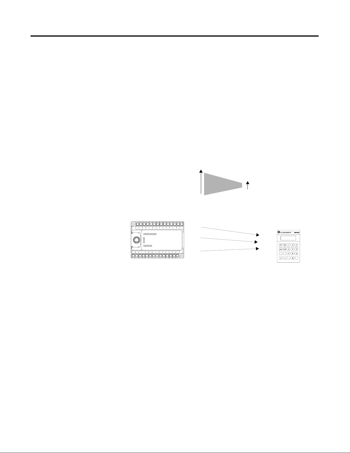
For application program transfers, you need a programming cable
(Catalog No. 2707-NC8) to connect the computer to the MicroView
communications port. You also need an external power supply to
power the MicroView for program uploads and downloads. Refer to
the MicroView User Manual (Catalog No. 2707-UM005B-EN-P) for
additional download/upload information.
Making a Backup Copy
Installation Files
Make a backup copy of the MicroView programming software
diskette. Insert the supplied disk into the diskette drive and use either
the DISKCOPY or COPY command of your installed DOS version.
Refer to your DOS manual for information and procedures regarding
these commands.
After you have created a duplicate disk, store the original in a safe
place and use the backup disk for normal operations.
The files on the installation disk are compressed and remain
compressed until they are installed. Once installed, the following files
are contained in the subdirectory:
DPS.EXE – MicroView Programming Software
DPS_CFG.EXE – DPS Configuration Utility.
MDPS_100.SLB – Operating systems for the MicroView. The version
noted here is 1.00.
Publication 2707-PM002B-EN-P
Page 13

Installing and Running the MicroView Programming Software 2-3
Installing MicroView Programming Software
This section shows how to install the software on a personal computer
with at least 1 hard disk drive and 1 floppy disk drive. The software is
1
supplied on one high density 3
/2 inch disk
1. Turn on your computer. Your computer prompt will display the
currently active drive: A:, B:, or C:
2. Insert the DPS installation disk into the floppy drive.
3. Select the drive containing the disk (A: or B:) and press [Return].
Normally this is the A: drive.
C:> A: [Return]
A:>
4. Type install and press [Return] to start the installation.
A:> install [Return]
The following screen appears:
This program will install Bul. 2707 MicroView Prog. S/W V1.00
on your computer system and verify the integrity of the
distribution disk(s).
You may press the [Esc] key at any time to abort the installation.
Each question has a default answer. If the default answer is
correct, press the ENTER key in response to the question.
Otherwise, type the answer and then press the ENTER key.
Press [Esc] to quit, any other key to continue . . .
Publication 2707-PM002B-EN-P
Page 14
2-4 Installing and Running the MicroView Programming Software
5. Press any key (other than [Esc] ) to continue.
This screen appears.
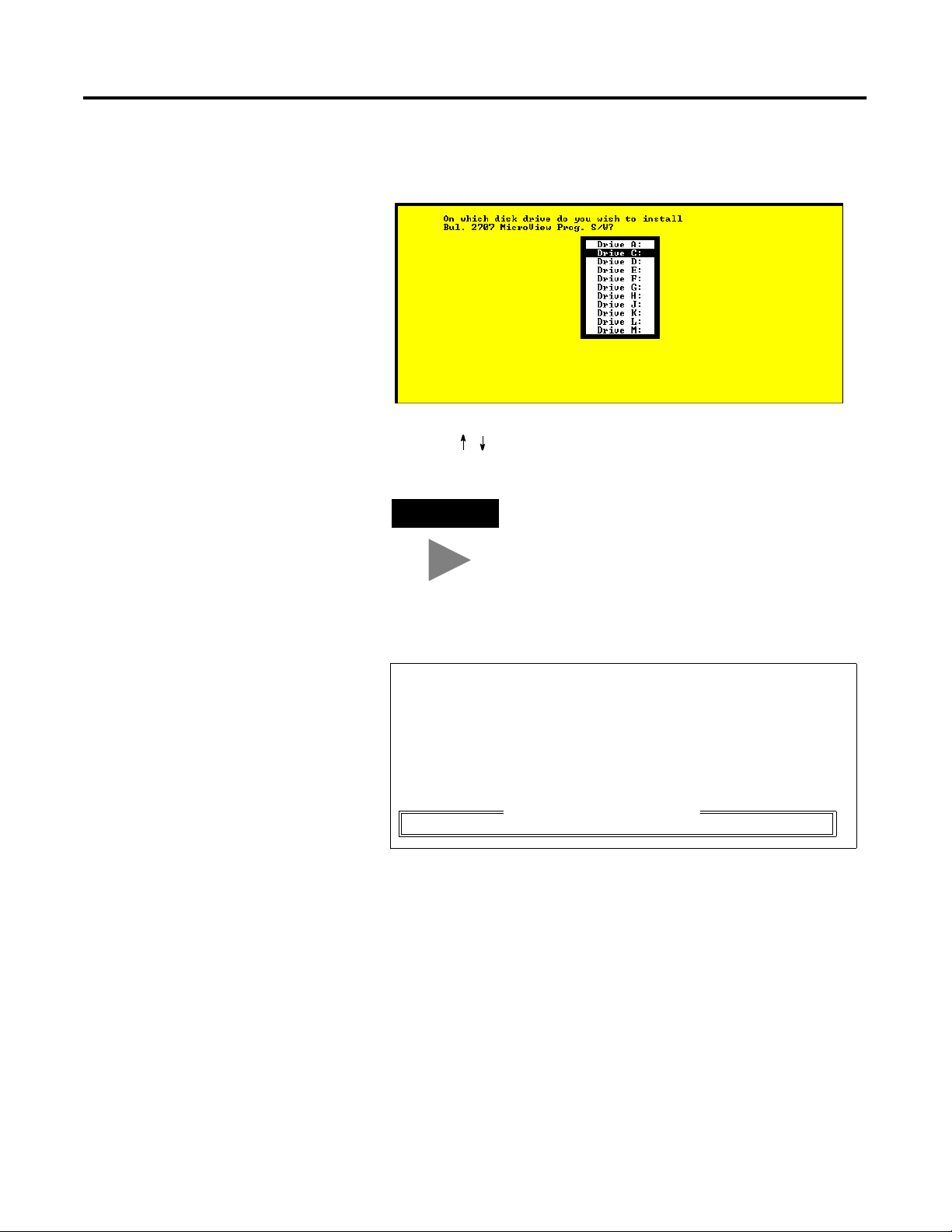
6. Use the [ ][ ] arrow keys to highlight the drive on which you
want to install DPS and press [Return]. The default drive is C:
TIP
You cannot install the DPS software on the
same drive the Install program resides.
This screen appears:
Now you need to specify the disk destination subdirectory.
The subdirectory is the location on your disk where the
Bul. 2707 MicroView prog. S/W will be installed.
If you don’t know what a “subdirectory” is, you probably
need not worry about it, and should press [Enter] for the next
prompt (don’t type the quote characters).
\MDPS
Which subdirectory ([Enter] = \MDPS) ?
Publication 2707-PM002B-EN-P
Page 15
Installing and Running the MicroView Programming Software 2-5
7. Press [Return] to install the DPS software in the \MDPS
subdirectory. The Install program creates the subdirectory. If
you enter your own subdirectory name, the entire path name
including colons, forward slash, and name should not exceed 28
characters.
The status of the installation is displayed on the screen.
The DPS Configuration Utility screen then appears:
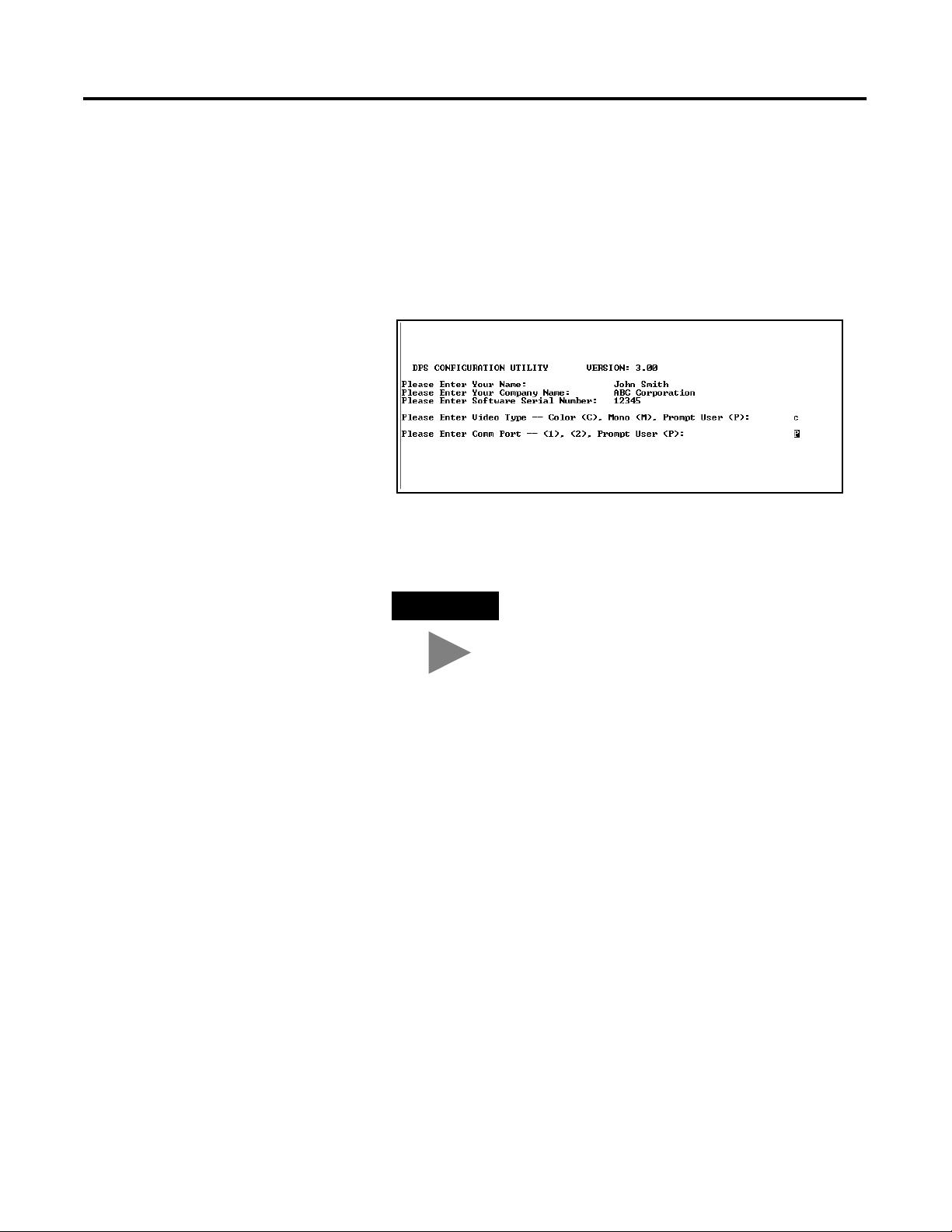
8. Enter your name, company name, and software serial number
(on registration card). Also, enter the monitor type and
communication port used by your computer.
TIP
Press [Return] at the Video Type and Comm
Port questions to prompt the user for this
information during application development.
The software serial number is required when requesting phone
support (refer to startup screen on next page).
9. After responding to the above questions, you are asked to
confirm the configuration. Press [Return] to accept the
configuration.
10. The installation is complete. You are returned to DOS at the
new subdirectory C: \MDPS>.
Publication 2707-PM002B-EN-P
Page 16
2-6 Installing and Running the MicroView Programming Software
Running DPS
To run the MicroView Programming Software:
1. Verify that you are at the \MDPS subdirectory where the
software resides.
If you are not, enter cd \MDPS and press [Return].
C:\MDPS>
2. Type DPS and press [Return] to start the program.
C:\MDPS> DPS [Return]
3. Specify whether you are using a color monitor. Enter [Y] or [N].
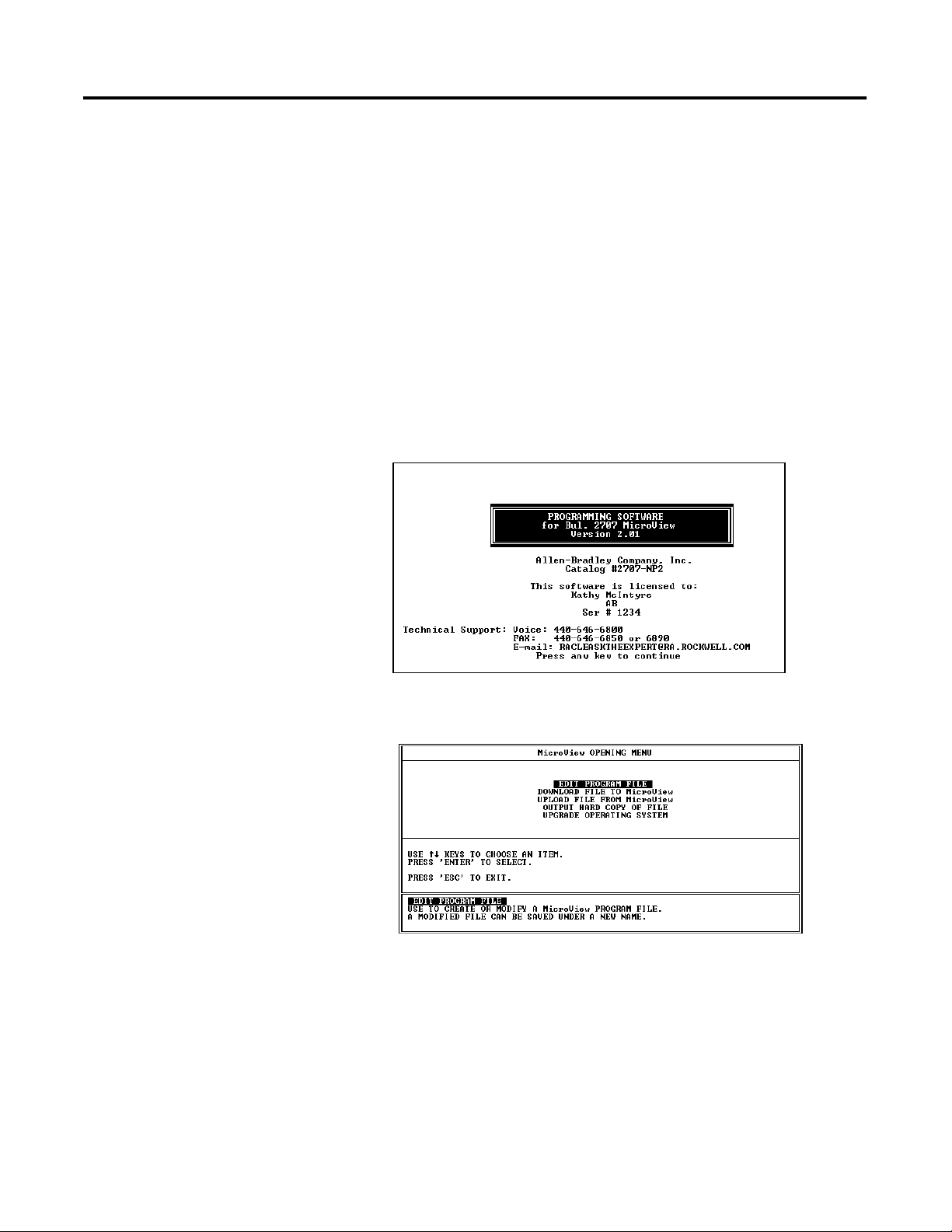
The startup screen displays. It identifies the MicroView version
and licensed owner. A phone support number is provided for
your assistance.
When you press any key, the Opening Menu appears:
You are now ready to create a file for your application.
Publication 2707-PM002B-EN-P
Page 17
Installing and Running the MicroView Programming Software 2-7
Menu Conventions
The following shows the format of DPS menu screens:
Menu
Window
Operations
Window
Information Window
Menu Window
The Menu Window lists operations available at the current menu. To
select one of the operations, use the cursor keys to highlight the
operation and press [Return].
Operations Windows
The Operations Window displays keyboard operations available at the
current Menu Window.
Information Window
The Information Window displays a brief explanation of each
operation available for the selected menu item.
Publication 2707-PM002B-EN-P
Page 18
2-8 Installing and Running the MicroView Programming Software
Screen Building Conventions
Application programs are written or edited using the Screen Builder.
Chapter 5 provides you with detailed instructions on how to use this
screen for creating application programs. The following shows the
Screen Builder format:
Display Window
Parameters
Window
Control Window
Information Window
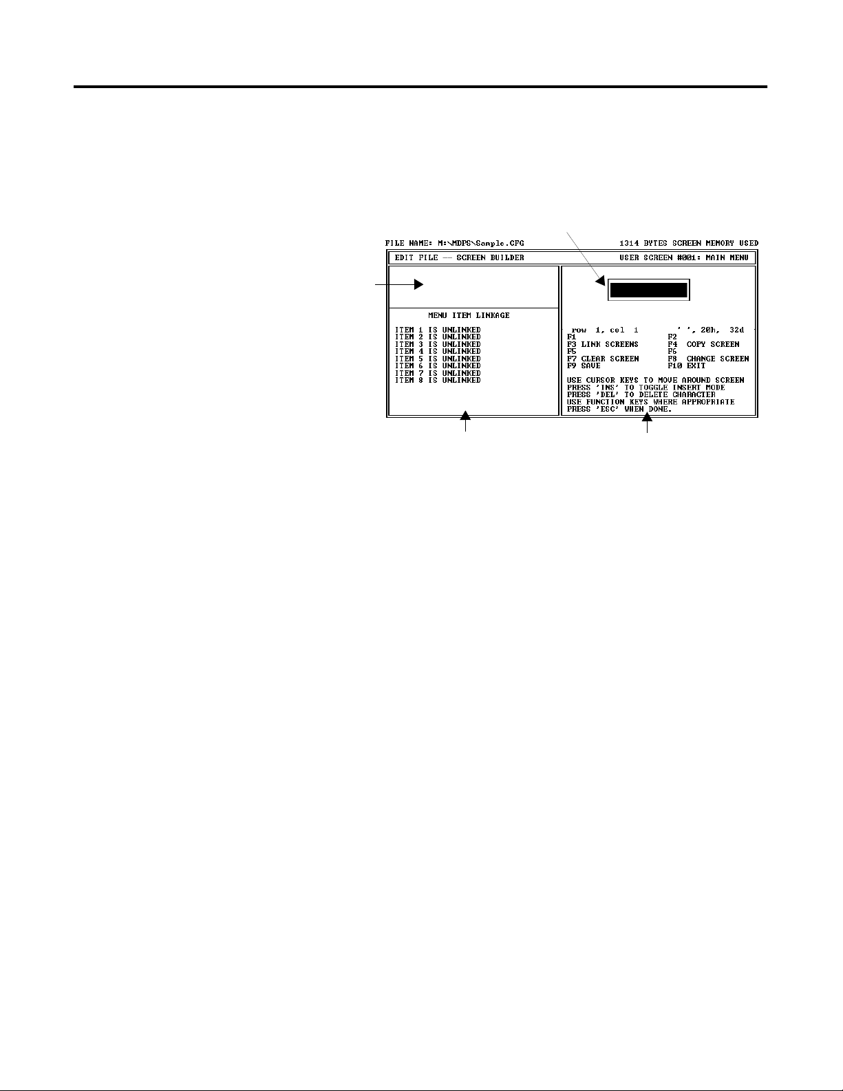
There are two information lines at the top of the screen:
• The first line identifies the current program path and file name,
as well as screen memory usage to help you track the size of
your program file.
• The second line identifies the current DPS operating area as well
as the current screen number and type.
Screen Builder has 4 windows:
Parameters Window
The Parameters Window displays the linking definitions that have
been established for the current screen.
Display Window
The Display Window simulates the MicroView (2 line display) screen.
It displays the formatted data and text as it would appear to the
MicroView operator.
Control Window
The Control Window displays the available data format selection and
the register information which can be defined for the current screen.
Information Window
The Information Window displays information about the function key
and keyboard operations available at the current screen.
Publication 2707-PM002B-EN-P
Page 19
Installing and Running the MicroView Programming Software 2-9
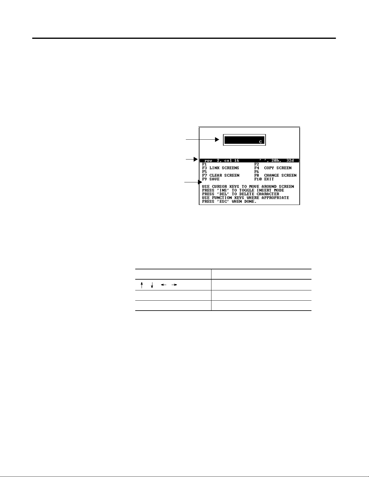
Cursor Status Line
The cursor status line is located between the Display and Information
windows. This line displays the current row and column of the cursor.
Also listed is the character at that position along with the character
ASCII code in hex and decimal formats. Confirm character codes by
placing the cursor under the character and reading the code from the
cursor status line.
The following example shows the character C at row 2, column 15.
Display Window
Cursor Status Line
Information
Window
Moving Around Screens
Linking Application Screens
DPS uses menus to guide you through the application development
process. Select a menu item and the next menu or screen is displayed.
The standard keyboard operations are:
Use these keys: To:
[
] [] [] []
[Return] Select a menu item.
[Esc] Return to the previous menu.
MicroView application files allow you to present screens in a
meaningful sequence, a hierarchy of possible tasks and operations.
To do this, you will need to specify a link for each screen.
The linking function is the basis of a MicroView operator terminal’s
power and flexibility. When screens are linked, the MicroView
becomes an interactive operator workstation, one that can guide an
operator through a hierarchy of operations. This hierarchy can be as
simple or as complicated as your application requires.
Highlight a menu selection.
Note: All application screens must be created before they can be
linked.
Publication 2707-PM002B-EN-P
Page 20

2-10 Installing and Running the MicroView Programming Software
Publication 2707-PM002B-EN-P
Page 21
Designing Microview Applications
Chapter
3
Chapter Objectives
MicroView Operator Terminal
This chapter provides guidelines for creating MicroView applications.
Section Page
MicroView Operator Terminal 3-1
MicroView File Types 3-2
Screen Types and Data Formats 3-3
Data Scaling 3-4
Application Example 3-6
Description of Example Application 3-7
Designing an Application 3-8
MicroView application programs are created using MicroView DPS.
The development of applications for the MicroView are very similar to
the DTAM Micro and DTAM Plus. The differences in application
development are related to differences in the operator terminals. The
following table lists MicroView Functional considerations.
Function MicroView
Screen Capacity Up to 50 Screens
Display Format 2 Line x 16 Character
Function Keys 2
Recipe Operations Yes
Advisor Option Yes
Screen Write Option Yes
Alarm Screens No
Point Access Display (P/AD) Yes
Auto Scaling Yes
Printer Port No
Mode Menu Changing of Comm. port Baud Rate
Mode Menu changing of Security Codes Yes
Processor Registers Supported MicroLogix
1 Publication 2707-PM002B-EN-P
Page 22
3-2 Designing Microview Applications
Function MicroView
Communications Port RS-232
Protocol MicroLogix DF1
Off line Programming Software 2707-NP, 2707-NP2, 2707-NP3
A major consideration when designing application programs is the
screen size of the MicroView.
MicroView Screen
2 Lines x 16 Characters
MicroView File Types
The MicroV ie w can read and wri te MicroLogi x controller f iles. Refe r to the
following when designing applications.
MicroLogix (DF1 File Types)
File Type
Output Yes Read O 0 0 NA 0-15
Input Yes Read I 1 0,1 NA 0-15
Status Yes Read / Write S 2 0-32 NA 0-15
Bit (Binary) Yes Read / Write B 3 0-31 NA 0-511
Timer Yes Read / Write T 4 0-39 PRE, ACC EN, TT, DN
HSC
(High Speed
Counter)
Counter Yes Read / Write C 5 1-31 PRE, ACC CU, CD, DN, OV, UN
Control Yes Read / Write R 6 0-15 LEN, POS EN, EU,
Integer Yes Read / Write N 7 0-104 NA 0–15
File Type
Supported By
MicroView
Yes Read / Write C 5 0 PRE, ACC CU, CD, DN, OV, UN,
Read / Write Identifier
File
Number
Element
Integer
Sub-Element
Bit Number
UA, HP, LP, IV, IN, IH, IL,
PE, LS, IE
DN, EM, ER, UL, IN, FD
Publication 2707-PM002B-EN-P
Page 23
Designing Microview Applications 3-3
Screen Types and Data Formats
Some application screens require that you specify register information.
Each MicroView screen type supports different data formats. The table
below lists each screen type and the data formats supported.
MicroLogix Controller
MicroLogix Data Formats
Format
Bit Yes Yes
16 Bit Signed Integer Yes Yes Yes
16 Bit Unsigned Integer Yes Yes Yes
16 Bit BCD Yes Yes Yes
16 Bit Hex Yes
ASCII Yes
Display
Screens
Data Entry
Screens
Recipe
Screens
Publication 2707-PM002B-EN-P
Page 24
3-4 Designing Microview Applications
Data Scaling
Data entered by an operator can be scaled from engineering units
such as gallons or PSI to machine control values. Likewise, data
displays can take raw numeric values and scale them so they are
displayed in engineering units.
Scaling of data is accomplished by defining a proportional ratio
between the register value range and the display or entry value range.
If a 1:1 ratio exists, the MicroView displayed or entered value equals
the controller register value.
Here is an example of scaling using a data display to scale a register
data range of 0 to 4,095 to a MicroView display range of -100 to +300.
Controller
Register Limits
MicroView
Display Limits
+300
-100
This Value
is Displayed:
+300
+100
-100
SCALING
If the Display
Register Contains:
4,095
SCALING
0
4,095
2,047
0
Publication 2707-PM002B-EN-P
When the ratio between the controller register values and MicroView
display or entry values is not a multiple of 2, the value is rounded.
Rounding may result in a 1 count error. Depending upon the
direction of the scaling, this means that:
When the ratio between the controller register values and MicroView
display or entry values is not a multiple of 2, the value is rounded.
Rounding may result in a 1 count error. Depending upon the
direction of the scaling, this means that:
• The MicroView display value may be off by 1 when the
controller register value is scaled
• The controller register value may be off by one when a
MicroView data entry is scaled.
An error screen appears if a rounding error occurs at the end points of
a data range. You must either increase the minimum or decrease the
maximum range of either the controller register or display ranges.
Page 25
Designing Microview Applications 3-5
Scaling Formulas
The scaling formula for a MicroView display value is:
Displayed Value = m x Register Value + b
Where:
Display Maximum Value - Display Minimum Value
m =
Register Maximum Value - Register Minimum Value
Display Maximum Value - Display Minimum Value - (m x Register Minimum Value)
b =
The scaling formula for an entered valued is:
Register Value = m x Entered Value + b
Where:
Register Maximum Value - Display Minimum Value
m =
Entry Maximum Value - Entry Minimum Value
Register Minimum Value - Entry Minimum Value - (m x Entry Minimum Value)
b =
Register Range = 0 to 4,095
Display Range = -100 to +300
Actual Register Value = 2,047
Scaling Example:
300 - (-100)
m =
4,095 - 0
= 0.0977
b = -100 - (0.0977 x 0) = -100
Displayed Value = 0.0977 x 2,047 + (-100)
= 99.9919
= 100
Publication 2707-PM002B-EN-P
Page 26
3-6 Designing Microview Applications
Application Example
Submenu
1. East Pmp/Tank
2. West Pmp/Tank
Data Display
East Pump is On
Tank is 38% Full
The following example shows typical menus and screens of a
MicroView application.
MicroView Application Outline
Data Display
West Pump is Off
Tank is 72% Full
Main Menu
1. Pmp/Tank Level
2. Pump Control
Security
* Limited Access *
Code: * * * * * * *
Submenu
1. East Pump
2. West Pump
Data Display
East Feed Pump
Run Time: 693 Hrs
Data Display
West Feed Pump
Run Time: 22 Hrs
Data Display
Setpoint = 94 CFM
New Setpoint:? _______
Data Display
Setpoint = 94 CFM
New Setpoint:? _______
Publication 2707-PM002B-EN-P
Page 27

Designing Microview Applications 3-7
Description of Example Application
Pump/Tank Levels
When Pump/Tank Levels is selected from the Main Menu, a Sub-Menu
displays two new choices (East Pump/Tank and West Pump/Tank).
Selecting either of these Sub-Menu items allows you to display pump
and tank information for the East or West systems.
Pump Control
Allows you to enter new pump setpoints to be entered. A security
code is required to access the Data Entry screens.
Data Entry screens use data from the controller (% Full & CFM) to
display this information along with a prompt to enter a new setpoint.
When a new setpoint is entered, the value is checked to verify that it
is within the programmed limits. If the value is within the entry limits,
the number is then scaled to engineering units and sent to the
controller. If the value is outside the limits, an error message informs
you of the valid range. You can then enter another value.
Appendix B contains worksheets for designing both MicroView
applications. Both application layout and screen design worksheets
are provided.
Publication 2707-PM002B-EN-P
Page 28
3-8 Designing Microview Applications
Designing an Application
Use the application design worksheets to layout a logical sequence of
screens. Make copies of the worksheets as needed. On each
worksheet, list the screen numbers, type of screens, register numbers,
etc.
Application Worksheet
Use the screen worksheets to define screen text and layout. Make
copies of the screen worksheets and write out each application
screen.
MicroView
Screen Worksheets
Screen # 1
Screen # 2
1
PUM
PUM P
30 P
P
0
2
LEVEL
P
RSSUREE
I
S
Before you design an application, become familiar with the types of
screens and how they function. To assist you, a sample application is
provided in this chapter. In addition, you should become familiar with
the controller files and data type supported for each operator module
type and selected protocol (see previous section). When register
information is required, this manual lists the applicable data formats
(such as ASCII or 16 Bit Hex) for each controller file type.
Publication 2707-PM002B-EN-P
Page 29

Designing Microview Applications 3-9
Recommended sequence for designing an application
1. On paper, design all the operator screens with the associated
register numbers, and produce a map of how all screens are
linked together.
2. Construct all screens using DPS. Save the program file without
linking.
3. Link the application screens. Use the design from step 1.
When you have established all links, save the program file.
An error display will warn you of any unlinked screens.
4. Download the application file.
5. Use the Simulate function (described in the MicroView User
Manual) to verify operations such as screen links, text, and
screen types.
6. Run the application.
Publication 2707-PM002B-EN-P
Page 30

3-10 Designing Microview Applications
Publication 2707-PM002B-EN-P
Page 31

Chapter
Creating or Editing an Application File
4
Chapter Objectives
Opening Menu
This chapter describes how to open, edit and save an application file.
Section Page
Opening Menu
Creating/Editing Application File
Saving Application File
The Opening Menu is the first menu displayed each time you run
the software.
TIP
If you specified prompts for the monitor type during
installation, these prompts will appear before the
opening menu.
4-1
4-2
4-3
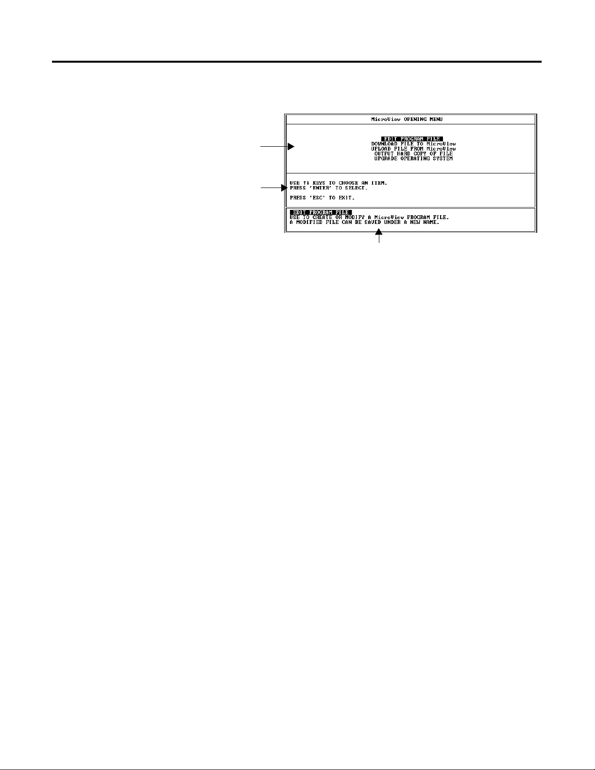
The Opening Menu displays the following operations:
• Edit Program File
• Download File to MicroView
• Upload File from MicroView
• Output Hard Copy of File
• Upgrade Operating System
1 Publication 2707-PM002B-EN-P
Page 32

4-2 Creating or Editing an Application File
Creating / Editing Applications
To create or edit an application:
1. Select Edit Program File to create or edit a MicroView
application file.
You are prompted for the file name to edit or create. All
MicroView application files in the current directory are listed.
If files already exist, each file name is followed by “-
MicroView”. Which is the type of Operating System the file was
created for.
2. Select the name of an existing application file or enter a new file
name. The new file name must be less than eight characters. Do
not use a file name extension. DPS automatically adds a “.CFG”
extension to each file name.
After you select an existing file or enter the new file name, the
following screen appears. Press [Return] to continue.
Publication 2707-PM002B-EN-P
Page 33

Creating or Editing an Application File 4-3
The Edit File - Option Selection menu is displayed.
3. Access the following functions from the Edit File - Option
Selection menu to create your application screens and enter
configuration data.
Select this Menu Option: To:
MicroView Configuration Data Set configuration and operating
parameters.
Saving Application File
Screen Builder Create or modify application screens.
Function Key Builder Assign application specific operations to
the MicroView function keys.
Save the application periodically while you are working on the
application screens and save the file again before you exit the
software.
To save an application periodically during editing:
1. Press [F9].
You are prompted to save the application under the current file
name or you can enter a new file name.
Publication 2707-PM002B-EN-P
Page 34

4-4 Creating or Editing an Application File
Note: If the same file name currently exists, you are prompted
if you want to overwrite the existing file.
FILE EXISTS!!! OVERWRITE? (Y or N)
2. Press [Return] to save the application under the file name
entered when the application file was opened.
Or enter a new file name of less than eight characters:
If you were creating a new file, the new file name replaces the
file name entered when the application was opened.
If you are editing an existing file, the original file is unchanged.
The file and all edits made prior to the last save are stored under
the new file name.
3. After saving the file, you can continue editing the application
program.
To save an application before exiting:
1. Exit the software by pressing [F10].
You are prompted save the application under the current file
name or you can enter a new file name.
2. If you enter a new file name, the original file is unchanged and
all edits are stored under the new file name.
After saving the file, you are returned to the DOS prompt.
Publication 2707-PM002B-EN-P
Page 35

Using Screen Builder
Chapter
5
Chapter Objectives
Screen Builder
This chapter describes how to use the Screen Builder to create or edit
application programs.
Section Page
Screen Builder 5-1
Accessing Screen Types 5-2
Editing Screen Displays 5-4
Copying Screens 5-5
Selecting Other Screens 5-6
Clearing Screens 5-7
Exiting Screen Builder 5-8
Screen Builder is one of the menu items available when you select
Edit Program File from the Opening menu. Use Screen Builder to
create:
• Menus and Sub-menus
• Data Entry screens
• Data Display screens
• Security screens
• Recipe screens
The Special menu security screen is not created within Screen Builder.
This screen is created using other DPS functions:
• For the Special menu security screen, see Chapter 12.
1 Publication 2711-PM002B-EN-P
Page 36

5-2 Using Screen Builder
Accessing Screen Types
To access Screen Builder screens:
1. Select Screen Builder from the Edit File - Option Selection menu.
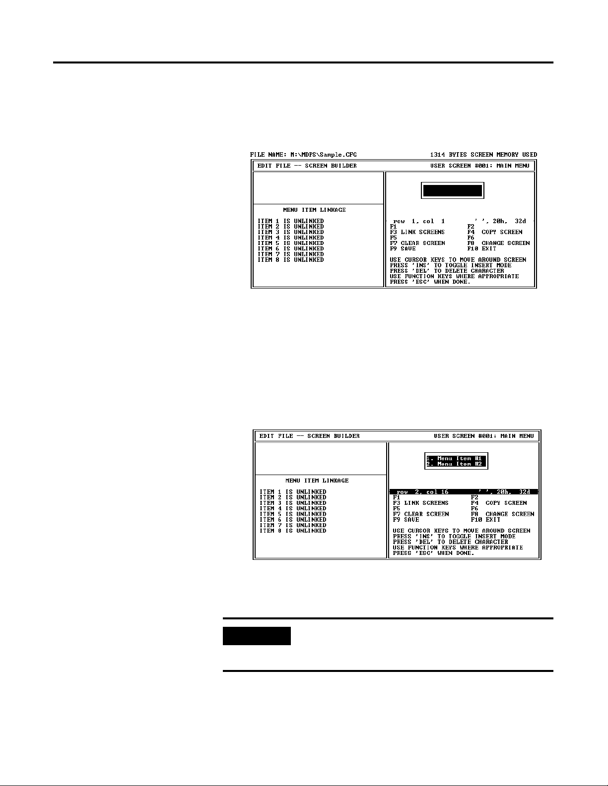
The Screen Builder for the main menu screen (screen #1)
displays:
Publication 2711-PM002B-EN-P
2. If you have designed your main menu screen, you can create it
now as described in Chapter 6. Each application must have a
main menu screen. If you want to create another screen type,
proceed to the next step.
Page 37

Using Screen Builder 5-3
3. Press [F8] on any screen to access the other screen types. You
are prompted for a screen number:
Press [F6] to go to the next available unused screen. Press [F8] to
view the next programmed screen. Press [F1] to go to the first
screen that you created. Press [F2] to go to the last screen of the
current program.
4. If you enter any screen number other than screen #1 (main
menu screen), you are prompted for a screen type:
5. Select a screen type. A Screen Builder for the selected screen
type is then displayed. Refer to Chapters 6 through 10.
Screen Type Chapter
Menus and Sub–Menus 6
Data Displays 7
Data Entry 8
Security 9
Recipe 10
Publication 2711-PM002B-EN-P
Page 38

5-4 Using Screen Builder
Editing Screen Displays
When you are editing screen text, the following editing operations are
available:
Screen Text Edit Functions
Screen Edit Key Function
[
] [] [] []
[Del] Deletes the character at the cursor position.
[Back Space] Deletes the character to the left of the cursor position.
[Ins] Toggles the insert mode on or off. Characters entered in
Move the screen cursor.
The cursor is moved to the left one space.
the insert mode are shifted to the right. A block shaped
cursor indicates the insert mode is on. An underline
cursor indicates that insert mode is off.
The extended MicroView character set can be used, refer to Appendix
A for additional information.
Screen Builder Function keys
The following function keys are available on most screen types.
Function Key Designation Function
[F3] LINK SCREENS Accesses screen mapping functions that link
application screens in a logical sequence.
Link screens only after all of the screens have
been created.
[F4] COPY SCREEN Copies an existing screen to or from the current
display window. Both the source and destination
screens must be of the same type (such as Data
Display screens).
[F7] CLEAR SCREEN Clears the current screen. You have the option of
clearing only the screen text or deleting the entire
screen including any linking you may have
established.
[F8] CHANGE
SCREEN
[F9] SAVE Saves the application without exiting the Screen
[F10] EXIT Prompts you to save the application to the current
Displays menu for selecting another screen.
Builder function.
file and exits the DPS software.
Publication 2711-PM002B-EN-P
Page 39

Using Screen Builder 5-5
Copying Screens
Use the copy function [F4] to save time when creating similar screens.
Both the source screen and the destination screen must be of the
same type. For example, you can’t copy Data Entry screen text into a
Data Display screen.
When you copy a screen, all register data and display text is also
copied. Edit the screen as needed after copying.
To copy a screen:
1. Open the screen you want to copy the screen to or from. In this
example, a Data Display screen:
2. Press [F4]. You are prompted for the screen to copy to or from:
3. Press [F1] to copy the current screen to another screen. Press
[F2] to copy another screen to the current screen.
You are prompted for a screen number.
Publication 2711-PM002B-EN-P
Page 40

5-6 Using Screen Builder
4. Enter the screen number and press [Return].
The screen is copied.
5. Edit the copied screen text and/or register data, refer to
descriptions of individual screen types (Chapters 6 through 10).
After you have completed an application screen, use [F8] Change
Screen to edit another screen. You can change to any screen.
Selecting Other Screens
To change screens:
1. Select [F8] Change Screen.
2. Enter the screen number you want to change to or select one of
the function keys:
Function Key Designation Function
[F1] FIRST SCREEN Returns to screen #1, the main menu.
[F6] NEXT UNUSED Selects the next unused screen.
Publication 2711-PM002B-EN-P
[F7] LAST SCREEN Selects the last programmed screen.
[F8] NEXT PROG Selects the next programmed screen.
The selected screen is displayed.
Page 41

Using Screen Builder 5-7
Clearing Screens
Use the [F7] Clear Screen function to clear all or part of the currently
displayed screen.
To clear a screen:
1. Open the screen you want to clear.
2. Select [F7] Clear Screen.
You are prompted for a clear screen option:
3. Select the Clear Screen option.
Function Key Function
ENTER
[Return]
DELETE
[Del]
ESCAPE
[Esc]
Clear the display text only. Screen linking and register data
for the screen are not deleted.
Clears the entire screen including screen display text, register
data, and screen links.
Cancels the clear screen function.
The screen is cleared.
4. Continue editing or change to another screen.
Publication 2711-PM002B-EN-P
Page 42

5-8 Using Screen Builder
Exiting Screen Builder
You can exit Screen Builder at any time during the design of an
application. Screen edits are not lost when you exit Screen Builder,
however, we recommend that you press [F9] SAVE before exiting.
To exit Screen Builder:
1. Press [Esc].
If you haven’t established screen linking, you are provided a
reminder:
WARNING 01: Screen Number 002 has not been mapped.
WARNING 01: Screen Number 003 has not been mapped.
WARNING 01: Screen Number 007 has not been mapped.
WARNING 01: Screen Number 008 has not been mapped.
WARNING 01: Screen Number 011 has not been mapped.
PRESS ‘Y’
2. Press [Y] to acknowledge the reminder (if displayed).
After exiting Screen Builder, the Edit File - Option Selection
menu is displayed.
Publication 2711-PM002B-EN-P
You can re-enter Screen Builder later for additional edits or to
establish screen linking.
Page 43

Chapter
Creating Menu and Sub-Menu Screens
6
Chapter Objectives
Menu Screens
This chapter describes how to create the main menu and sub–menu
screens.
Section Page
Menu Screens 6-1
Building a Menu 6-2
Main Menu and Sub-Menu Screen Builder 6-3
Creating a Menu Screen 6-4
Menu Screens provide easy access to different parts of an application.
Menus structure an application on the basis of specific tasks and
responsibilities.
Each menu screen may consist of up to 8 different menu items. When
selected (by pressing a corresponding numeric key), a menu item
displays the linked screen or sub-menu.
A typical menu screen might look like this:
1. TEMP.
2. MONITOR
3. LEVEL
Main Menu Screens
Sub-Menu Screens
1 Publication 2707-PM002B-EN-P
The Main Menu is always operator screen #1. This menu lists the
primary components of your application. All other menus and data
screens are accessed from this screen.
There are two differences between the main menu and sub-menus:
• The MicroView [MENU] key displays the Main Menu. This key is
active at all times.
• The Main Menu is the first screen that appears after a restart or
reset.
Sub-menu screens are identical in appearance to the main menu
screen. Sub-menu screens enable you to expand the scope of an
application by providing directed choices through linked menus. This
allows you to construct a large application and maintain efficient
access to specific areas.
Page 44

6-2 Creating Menu and Sub-Menu Screens
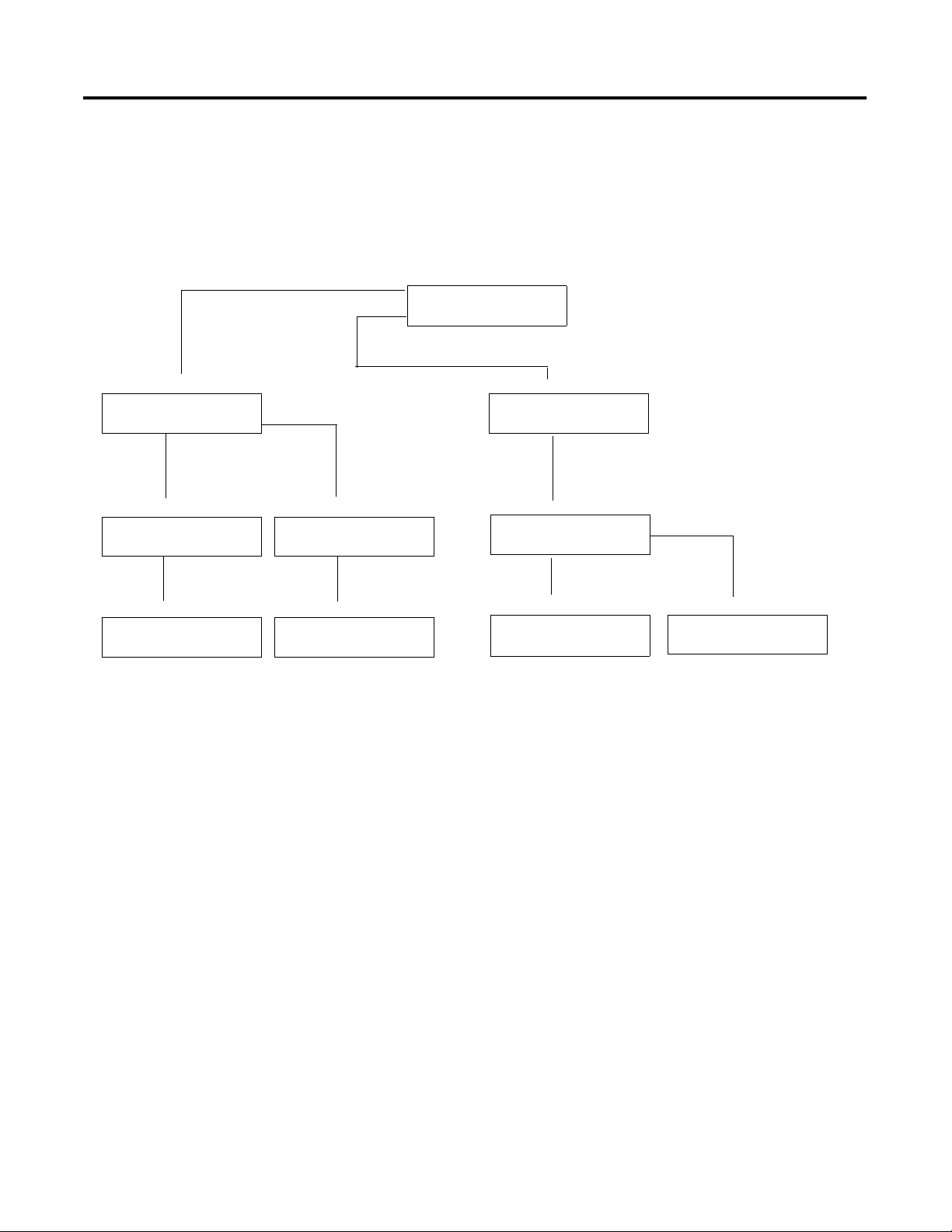
Building a Menu
When you build a menu, you are directing the operator to more
specific screens. A menu is a numbered list of components available
at the current stage of a process. Number each successive menu entry
sequentially. The number tells the operator which MicroView keypad
key ([1] through [8]) to press for each menu item (1 through 8).
The following example shows the menu structure of a MicroView
application. The operator uses the MicroView numeric keypad keys to
select a menu item. Pressing [1] on the keypad selects the Pump Status
screen. Screen #11 is linked to keypad key [1] on the MicroView while
this menu is displayed. Pressing keypad key [2] on the MicroView
displays another menu which has different links assigned to keypad
keys [1] and [2].
Main Menu
1. Pump Status
2. Tank Information
Screen 11
East Pump is ON
West Pump is ON
Sub-Menu
1. Temperature
2. Tank Level
Screen 20
Items 1 through 8 correspond
to MicroView keypad keys 1
through 8. Each key can be
linked to a screen number.
Screen 40
East Tank = 36 C
West Tank = 54 C
Screen 39
East Tank = 75% Full
West Tank = 48% Full
To assign menu text, position the cursor at the location you want the
list to begin and enter text.
Enter
Menu
Text here .
Screens can’t be linked to MicroView keypad keys ([1] – [8]) until you
have first created the screens. After creating your application screens,
you can return to the menu screens and assign the links, refer to
Chapter 11.
Publication 2707-PM002B-EN-P
Page 45

Creating Menu and Sub-Menu Screens 6-3
Main Menu and Sub-Menu Screen Builder
The screen for creating the main menu and sub-menu screens is the
same. Both the main menu and sub menu screens can display up to a
16 character two line message.
Menu Screen Builder Function Keys
Function
Key
[F3] LINK
Designation Function
Accesses screen mapping functions that link
SCREENS
application screens in a logical sequence.
Link screens only after all of the screens have been
created. Refer to Chapter 11.
[F4] COPY
SCREEN
[F7] CLEAR
SCREEN
[F8] CHANGE
SCREEN
[F9] SAVE Saves the application without exiting the Screen
[F10] EXIT Prompts you to save the application to the current file
Copies an existing screen to or from the current
display window. Both the source and destination
screens must be of the same type (Menu screens).
Clears the current screen. You have the option of
clearing only the screen text or deleting the entire
screen including any linking you may have
established.
Selects another operator screen.
Builder function.
and exits the DPS software.
Publication 2707-PM002B-EN-P
Page 46
6-4 Creating Menu and Sub-Menu Screens
Creating a Menu Screen
To create a menu screen:
1. Select Screen Builder from the Edit File - Option Selection menu.
The Screen Builder for the main menu (screen #1) is displayed.
2. If you are creating a sub-menu, press [F8], enter the screen
number, and select a sub-menu screen type.
The screen builder for a sub-menu is displayed. The sub-menu
screen builder is the same as the main screen (shown above).
3. Enter the screen text. The sequence, length and location of the
text does not matter but make sure you number each menu item
(1 through 8).
Publication 2707-PM002B-EN-P
4. Press [F9] to save the screen.
IMPORTANT
You can’t link screens to a menu until all of the
application screens have been created. Chapter 11
describes how to link screens to a menu.
Page 47

Creating Data Display Screens
Chapter
7
Chapter Objectives
Data Displays
This chapter describes how to create data display screens.
Section Page
Data Displays 7-1
Scaling 7-1
Data Display Screen Builder 7-2
Creating a Display Screen 7-3
Display Register Format Selections 7-6
Data display screens allow you to monitor the value of registers in the
controller. The MicroView continuously reads the registers to update
(at a user-defined rate) the displayed values.
This is how a data display screen may appear:
Tank #1 = 33 Gal
10% Full
To construct data display screens, you need to specify:
• The type of screen as data display
• The type of data stored in the controller register
• The register to access (address)
• Any data format and display information
• The display position for the data
• Any additional text information that you want to display
Scaling
1 Publication 2707-PM002B-EN-P
Data in controller data files can be scaled to standard engineering
units such as gallons, pounds, feet, etc. Data is scaled by setting up a
proportion between the controller register data limits and the
MicroView data display limits. Refer to the description of scaling in
Chapter 3.
Page 48

7-2 Creating Data Display Screens
Data Display Screen Builder
The screen for creating data display screens has a maximum display
size of 2 lines of 16 characters.
Data Display Screen Builder Function Keys
Function
Key
[F1] DISPLAY REG Inserts data display field at the cursor point. Accesses
[F3] MAP SCREEN Accesses screen mapping functions that link application
Designation Function
the display register information.
screens in a logical sequence. Link screens only after all
of the screens have been created.
[F4] COPY SCREEN Copies an existing screen to or from the current display
window. Both the source and destination screens must
be of the same type (Data Display screens).
[F7] CLEAR
SCREEN
[F8] CHANGE
SCREEN
[F9] SAVE Saves the application without exiting the Screen Builder
[F10] EXIT Prompts you to save the application to the current file
Clears the current screen. You have the option of
clearing only the screen text or deleting the entire
screen including any linking you may have established.
Selects another operator screen.
function.
and exits the DPS software.
Publication 2707-PM002B-EN-P
Page 49

Creating Data Display Screens 7-3
Creating a Display Screen
The display register data field may be inserted anywhere on the
screen. The number of positions required for the data field depends
upon the register information you provide. You can insert the display
data while you are entering the screen text or you can leave spaces
and insert the data field later.
To create a data display:
1. Select Screen Builder from the Edit File - Option Selection menu.
The Screen Builder for the main menu (screen #1) is displayed.
2. Press [F8] and enter the display screen # or press [F6] for the
next unused screen.
3. You are then prompted to choose a screen type. Select Data
Display Screen and press [Return].
The Screen Builder for a data display screen appears.
Publication 2707-PM002B-EN-P
Page 50

7-4 Creating Data Display Screens
4. Enter the screen text to the point where you want the data
display field to be inserted. You can either leave spaces for the
display field or enter the display field at this time. Position the
cursor where you want to insert the data display.
5. Press [F1] to insert a display register.
IMPORTANT
32 Bit Register Types appear in the list but
are not available.
You are prompted to select a register type. Refer to Chapter 3
for a list of the applicable file types for MicroLogix DF1 protocol.
6. Select a register type.
You are prompted for data specific to the selected register type:
16 Bit Signed Integer Shown
Publication 2707-PM002B-EN-P
7. Enter the register data. Refer to the next section Display Register
Format Selections.
Page 51

Creating Data Display Screens 7-5
8. After entering the register data, press [Esc] to save the data and
return to the screen editing. The data display register field is
indicated by a series of asterisks ****. The number of asterisks
and format (decimal point and sign) is determined by the
register data you entered.
Data Display Register
9. Enter the remainder of the screen text or additional display
registers and press [F9] to save the screen.
Move the cursor off the data display field using the arrow keys
before entering additional screen text. If you attempt to enter
text over a display field you will be prompted:
WAR NING !
You are about to delete
a register definition.
PRESS ‘Y’ to proceed.
PRESS ‘N’ to abort.
Publication 2707-PM002B-EN-P
Page 52

7-6 Creating Data Display Screens
Display Register Format Selections
See Appendix C
for default Bit text.
When inserting a data display field, you must provide register
information that determines the address and format of the data being
displayed. This section describes options available for data display
registers.
Bit
The register information for a Bit display is shown below.
Format Selection Description
Register Number The controller address from which the bit will be
monitored.
Bit Number The Bit number of a multiple bit address which will be
monitored for status if the register number designates a
multiple bit address (a 16 bit data address, for example).
This selection is unavailable if the register number refers
to a Bit type address.
Text when Bit is OFF (0) The text description (16 character maximum) to be
displayed when the bit is in an OFF (0) state.
Text when Bit is ON (1) The text description (16 character maximum) to be
displayed when the bit is in an ON (1) state.
Publication 2707-PM002B-EN-P
Page 53

Creating Data Display Screens 7-7
16 Bit Signed Integer, 16 Bit Unsigned Integer, 16 Bit BCD (Binary
Coded Decimal)
The screen for a 16 Bit Unsigned Integer format is shown below. The
screens for 16 Bit Signed Integer and 16 Bit BCD formats are similar.
Format Selection Description
Register Number The controller address from which the integer will be monitored.
Digits Right of Decimal The number of digits to be placed to the right of the decimal.
Digits Left of Decimal The number of digits to be placed to the left of the decimal.
Leave Place for Sign (Y or N) Provides for a one character place for the polarity sign (+ or –)
Show Leading Zeros (Y or N) Provides for any zeros to the left of the data, if desired.
Minimum Register Value The minimum data value of the controller address being
Maximum Register Value The maximum data value of the controller address being
Minimum Displayed Value The minimum data value to be displayed. This value is displayed
Maximum Displayed Value The maximum data value to be displayed. This value is displayed
when the data is displayed, if desired.
monitored.
monitored.
when the data in the controller address is equal to the minimum
register value and scaling is enabled.
when the data in the controller address is equal to the maximum
register value and scaling is enabled. The range defined by the
Minimum Displayed Value and the Maximum Displayed Value is
proportionally scaled to the range of the minimum and maximum
register values. If both ranges are equal then the scaling ratio is
1:1.
Publication 2707-PM002B-EN-P
Page 54

7-8 Creating Data Display Screens
16 Bit HEX (Hexadecimal)
The screen for a 16 Bit Hex format is shown below.
Format Selection Description
Register Number The controller address to be monitored.
IMPORTANT
The scaling of data is not supported for the
hexadecimal selections.
Publication 2707-PM002B-EN-P
Page 55

Creating Data Display Screens 7-9
ASCII
The screen for an ASCII format is shown below:
Format Selection Description
Register Number The controller address to be monitored.
Character Count The number of characters (2 characters for each 16 bit
data address) to be displayed, up to a maximum of 2
characters. The initial byte of the address identified by the
register number is displayed first, then the second byte,
the first byte of the next higher sequential address, and so
on. To display 16 characters, a sequential block of eight 16
bit addresses is read by the MicroView.
First Character in LSB or
MSB
Indicates placement of first ASCII character to be read. If
LSB, the first character is in bits 0 to 7 of the register. If
MSB, the first character is in bits 8 to 15 of the register
Each data display can only be 16 bit data or 2 characters. Multiple data
entries can be created in sequence up to 28 total.
Publication 2707-PM002B-EN-P
Page 56

7-10 Creating Data Display Screens
Publication 2707-PM002B-EN-P
Page 57

Creating Data Entry Screens
Chapter
8
Chapter Objectives
Data Entry Screens
This chapter describes how to create data entry screens
Section Page
Data Entry Displays 8-1
Scaling 8-1
Data Entry Screen Builder 8-2
Creating a Data Entry Screen 8-3
Data Entry Register Format Selections 8-6
Data entry screens allow an operator to directly enter values into
MicroView registers. Data entry screens can also contain data display
fields.
This is how a data entry screen may appear:
Temp = 150 Deg. C
Desired:
(Must be last on screen)
Data Display Field
Data Entry Field
To construct data entry screens, you need to specify:
• The type of screen as data entry
• Any additional text information that you want to display
• The type of data stored in the controller register
• The register to access (address), and if used, a display register
• Any data format and display information
• The display position for the entry field
Scaling
1 Publication 2707-PM002B-EN-P
Data entered in standard engineering units such as gallons, pounds,
feet, etc. can be scaled to machine control values. Data is scaled by
setting up a proportion between the MicroView data entry limits and
the controller register data limits. Refer to the description of scaling in
Chapter 3.
IMPORTANT
The 16 bit data format cannot be scaled.
Page 58

8-2 Creating Data Entry Screens
Data Entry Screen Builder
The screen for creating data entry screens has a display size of 2 lines
of 16 characters.
Data Entry Screen Builder Function Keys
Function
Key
[F1] DISPLAY REG Inserts data display field at the cursor point. Accesses
Designation Function
the display register information.
Note: Display values must be positioned before the
data entry field.
[F2] ENTRY REG Inserts data entry field at the cursor point. Accesses
the entry register information.
[F3] MAP SCREEN Accesses screen mapping functions that link
application screens in a logical sequence. Link
screens only after all of the screens have been
created.
[F4] COPY SCREEN Copies an existing screen to the current window.
Both the source and destination screens must be of
the same type (Data Entry screens).
[F7] CLEAR SCREEN Clears the current screen. You have the option of
clearing only the screen text or deleting the entire
screen including any linking you may have established.
[F8] CHANGE
SCREEN
[F9] SAVE Saves the application without exiting the Screen
[F10] EXIT Prompts you to save the application to the current file
Selects another operator screen.
Builder function.
and exits the DPS software.
Publication 2707-PM002B-EN-P
Page 59

Creating Data Entry Screens 8-3
Creating a Data Entry Screen
The entry register data field may be inserted anywhere on the screen,
however, no text may follow the data entry field. This means that you
must insert any text or a display field before the data entry field. The
number of character positions required for the data entry field
depends upon the register information you provide.
To create a data entry screen:
1. Select Screen Builder from the Edit File – Option Selection
menu.
The Screen Builder for the main menu (screen #1) is displayed.
2. Press [F8] and enter the display screen # or press [F6] for the
next unused screen.
You are then prompted to choose a screen type.
3. Select Data Entry Screen and press [Return].
The Screen Builder for a data entry screen appears.
Publication 2707-PM002B-EN-P
Page 60

8-4 Creating Data Entry Screens
4. Create all of the screen text and, if used, a data display field.
Refer to Chapter 7 for information on how to insert a data
display field. The same procedures apply to a data display on
the data entry screen.
5. Position the cursor where you want to insert the data entry field.
Display Field and Text
Data Entry
Position
6. Press [F2] to insert a data entry register.
Publication 2707-PM002B-EN-P
You are prompted to select a register type. Refer to Chapter 3 for
a list of the applicable register types for each.
Page 61

Creating Data Entry Screens 8-5
7. Select a register type.
You are prompted for data specific to the selected register type:
8. Enter the register data. Refer to the next section Data Entry
Register Format Selections.
9. After entering the register data, press [Esc] to save the data and
return to the screen editing. The data entry register field is
indicated by a series of diamonds. The number of diamonds
and format (decimal point and sign) is determined by the
register data you entered.
Data Entry Register
10. Press [F9] to save the screen, any text entered after the data entry
field will not be displayed.
Publication 2707-PM002B-EN-P
Page 62

8-6 Creating Data Entry Screens
Data Entry Register Format Selections
When inserting a data entry field, you must provide register
information that determines the address and format of the data storage
location. This section describes options available for data entry
registers.
Bit
The screen for a Bit format is shown below
Format Selection Description
Register Number The controller data address to be monitored.
Bit Number The Bit number if the register number designates a
multiple bit address (a 16 bit data address, for example).
This selection is unavailable if the register number refers
to a Bit type address.
Default Value ?
Z = No Default
(Enter 1,0,Z)
This parameter defines the default value that is displayed
at the data entry position of the MicroView display. If a
default value of 1 is entered, a 1 is displayed, and the
operator is only required to press ENTER to set the bit
address.
An entry of Z defines no default value. NONE appears in
the window when Z is entered.
Publication 2707-PM002B-EN-P
Page 63

Creating Data Entry Screens 8-7
16 Bit Signed Integer,
16 Bit Unsigned Integer,
16 Bit BCD Binary Coded Decimal)
The screen for a 16 Bit Unsigned Integer format is shown below. The
screens for 16 Bit Signed Integer and 16 Bit BCD formats are similar.
Format Selection Description
Register Number The controller data address to be monitored.
Digits Right of Decimal The number of digits to be placed to the right of the decimal.
Digits Left of Decimal The number of digits to be placed to the left of the decimal.
Leave Place for Sign (Y or N) Provides for a one character place for the polarity sign (+ or –)
Minimum Register Value The minimum data value of the controller address being
Maximum Register Value The maximum data value of the controller address being
Minimum Entry Value The minimum data value to be entered. When this value is
Maximum Entry Value The maximum data value to be entered. When this value is
Low User Input Limit The minimum entry value that an operator may enter. If a value
High User Input Limit The maximum entry value that an operator may enter. If a value
Default Value This parameter defines a default value that is displayed at the
when the data is displayed, if desired.
monitored.
monitored.
entered the minimum register value is entered to the defined
controller address when scaling is enabled.
entered the maximum register value is entered to the defined
controller address when scaling is enabled. The range defined
by the minimum entry value and the maximum entry value is
proportionally scaled to the range of the minimum and maximum
register values. If both ranges are equal then the scaling ratio is
1:1.
lower than this limit is entered the MicroView will display an
“Input Error” screen displaying the minimum and maximum
entry limits.
higher than this limit is entered the MicroView will display an
“Input Error” screen displaying the minimum and maximum
entry limits.
entry address of the display. An entry of Z defines no default
value. NONE appears in the window when Z is entered.
Publication 2707-PM002B-EN-P
Page 64

8-8 Creating Data Entry Screens
Publication 2707-PM002B-EN-P
Page 65

Creating Security Screens
Chapter
9
Chapter Objectives
Security Screens
This chapter describes how to create security screens.
Section Page
Security Screens 9-1
Security Screen Builder 9-2
Creating a Security Screen 9-3
Security screens use numeric codes to restrict access to any associated
information or processes. For ease of programming, security screens
are provided with default text:
*LIMITED ACCESS*
CODE:
If a different message is required, the security screen text can be
edited. Constructing a security screen usually consists of assigning the
security code(s).
As an operator enters a security code, an asterisk (
the MicroView for each character input on the keyboard. If a valid
security code has been entered, the next linked screen is displayed. If
an invalid security code is entered, an error message appears. Once
the error condition is acknowledged, the operator can re-enter the
code or return to the Main Menu.
) is displayed on
*
1 Publication 2707-PM002B-EN-P
Page 66

9-2 Creating Security Screens
Security Screen Builder
This is the Security Screen Builder display.
Security Screen Builder Function Keys
Function
Key
[F1] EDIT CODES Allows previously entered codes to be edited.
[F3] MAP
Designation Function
Accesses screen mapping functions that link
SCREEN
application screens in a logical sequence. Link screens
only after all of the screens have been created. Refer
to Chapter 11.
[F4] COPY
SCREEN
[F7] CLEAR
SCREEN
[F8] CHANGE
SCREEN
[F9] SAVE Saves the application without exiting the Screen
[F10] EXIT Prompts you to save the application to the current file
Copies an existing screen to or from the current display
window. Both the source and destination screens must
be of the same type (Security screens).
Clears the current screen. You have the option of
clearing only the screen text or deleting the entire
screen.
Selects another operator screen.
Builder function.
and exits the DPS software.
Publication 2707-PM002B-EN-P
Page 67

Creating Security Screens 9-3
Creating a Security Screen
You can specify up to three separate codes for each Security Screen.
An operator is allowed access by entering any of the assigned security
codes.
To create a security screen:
1. Select Screen Builder from the Edit File - Option Selection menu.
The Screen Builder for the main menu (screen #1) is displayed.
2. Press [F8] and enter the display screen # or press [F6] for the
next unused screen.
3. You are then prompted to choose a screen type. Select Security
Screen and press [Return].
The Screen Builder for a security screen appears.
4. If no security codes have been previously defined, you are
prompted to enter a code(s).
Publication 2707-PM002B-EN-P
Page 68

9-4 Creating Security Screens
If you are editing a screen with a previously defined security
code(s), you must press [F1] to edit the code(s).
5. Enter at least one digit at each prompt. You can enter up to
eight digits. If less than eight digits are entered, each remaining
digit is displayed as a question mark (?). The question mark is a
wildcard character, designating any character entry as
acceptable.
6. To modify a security code, highlight the value and overwrite the
old code.
7. To save the security code(s), press [F9] or [Esc]. The cursor is
then returned to the display window where you can edit the
screen text.
8. Press [Esc] to save the screen and return to the Edit File - Option
Selection menu.
Publication 2707-PM002B-EN-P
Page 69

Creating Recipe Screens
Chapter
10
Chapter Objectives
Recipe Screens
This chapter describes how to create recipe screens.
Section Page
Recipe Screens 10-1
Recipe Screen Builder 10-2
Creating a Recipe Screen 10-3
Recipe Screens allow an operator to download a block of data for up
to 10 register addresses. These addresses can be in any order. Multiple
recipe screens may be linked together in sequential order to
download more than 10 register addresses, or to download more than
one data format. You can choose to initiate the download
automatically or manually (with a prompt).
If recipe screens are linked together, successive screens linked to the
first recipe screen are downloaded immediately following the first
screen. The operator prompt enabled for the first screen prompts the
operator to acknowledge the recipe download. If the other linked
recipes do not have the operator prompt enabled they are sent
automatically. This appears to the operator as though all recipes were
sent as one large recipe.
1 Publication 2707-PM002B-EN-P
Page 70

10-2 Creating Recipe Screens
Recipe Screen Builder
The screen for creating recipe screens is shown below:
Recipe Screen Builder Function Keys
Function
Key
[F3] MAP SCREEN Accesses screen mapping functions that link
Designation Function
application screens in a logical sequence. Link
screens only after all of the screens have been
created. Refer to Chapter 11.
[F4] COPY SCREEN Copies an existing screen to or from the current
display window. Both the source and destination
screens must be of the same type (Recipe screens).
[F8] CHANGE
SCREEN
[F9] SAVE Saves the application without exiting the Screen
[F10] EXIT Prompts you to save the application to the current file
Selects another operator screen.
Builder function.
and exits the DPS software
Publication 2707-PM002B-EN-P
Page 71

Creating Recipe Screens 10-3
Creating a Recipe Screen
To create a recipe screen:
1. Select Screen Builder from the Edit File - Option Selection menu.
The Screen Builder for the main menu (screen #1) is displayed.
2. Press [F8] and enter the display screen # or press [F6] for the
next unused screen.
3. You are then prompted to choose a screen type. Select Recipe
Screen and press [Return].
The Screen Builder for a recipe screen appears. You are asked
whether the operator is to be prompted before the recipe data is
downloaded (manual or automatic operation).
4. Enter [Y] or [N] and press [Return]. If you select [Y], the operator
is prompted to acknowledge the screen. The operator must
press [ ] on the MicroView. If you select [N], the download
occurs automatically when the screen is selected. The operator
in most cases will not even see the screen, only the message that
data is being downloaded.
Publication 2707-PM002B-EN-P
Page 72

10-4 Creating Recipe Screens
You are prompted for a register type.
IMPORTANT
32 Bit Register Types appear in the list but are
not available.
5. Select a register type and press [Return]. You are prompted to
enter the registers and the values you want to write.
6. Enter the register address and press [Return]. Enter the value to
send and press [Return]. Repeat for up to 9 more addresses that
you want to write at download.
Publication 2707-PM002B-EN-P
7. After entering the download data and addresses, press [Esc] to
accept the data.
8. Enter the screen text.
9. Press [F9] to save the screen or press [Esc] to save the screen and
return to the Edit File - Option Selection menu.
Page 73

Chapter
Linking Menu and Application Screens
11
Chapter Objectives
Linking Application Screens
This chapter describes how to link the application screens so that an
operator is presented with a logical flow of information.
Section Page
Linking Application Screens 11-1
Linking Menu Screens 11-2
Screen Linking Guidelines 11-2
Application Screen Linking Function Keys 11-3
Menu and Sub-Menu Linkage Display 11-4
Linking a Menu 11-4
Linking Example 11-5
After you have developed all of the screens necessary for an
application, you need to decide how to link them. It is very helpful to
create a flowchart of the screens to use as a map before you begin to
define the links.
The [PREV] and [NEXT] keys of the MicroView use the linking
information to move between screens. Not all links need to have a
“next” and “previous” screen. A screen link may create a two-way or
one-way relationship.
Two-way links utilize a Link function:
[PREV]
selected
One-way links only use a Goto function:
1 Publication 2707-PM002B-EN-P
Screen #20
[NEXT]
selected
Screen #30
Screen #20
[NEXT]
selected
Screen #30
Page 74

11-2 Linking Menu and Application Screens
Linking Menu Screens
Screen Linking Guidelines
Menu and sub-menu links provide one way links with up to 8
application screens or sub-menus. An operator selects a menu item
by pressing the numeric key corresponding to the menu item. When
you link the main menu and sub-menu items you are linking screens
to the keys on the numeric keypad.
1. Menu 3. Level
2. Temperature
Tank Level
33 Gallons
Temperature
is 55 C.
1. Pump Control
2. Pump Output
The following rules apply to linking screens:
• Only screens that are already defined can be linked.
• Wait until you have developed all of your screens and menus
before establishing links. It is much easier to create your links
once, rather than change them whenever you change the order
of screens.
• A non-menu screen cannot be linked back to a menu screen,
use a Goto (one way) link instead.
• A link is a one-to-one relationship between the current screen
and the target screen. You cannot establish more than a single
one-way link to any particular screen.
Publication 2707-PM002B-EN-P
If you attempt to link to a destination screen that is already linked,
you have the option of inserting the screen (changing the current link)
or aborting the operation.
WARNING!!! That screen has already
been mapped.
PRESS ‘Y’ to insert this screen
between screen XX and screen XX.
Press ‘N’ to abort.
Screen Being Linked
to Target Screen
Other Screen Already
Linked to Target Screen
Page 75

Linking Menu and Application Screens 11-3
Application Screen Linking Function Keys
When you press [F3] MAP Screen on a non-menu screen, the screen
linking function keys are active. Shown below is an example using a
data display screen, the other screen types are similar.
Screen Linking Function Keys
Function
Key
[F1] INSERT LINK Inserts a link between two screens. This link is bi–
Designation Function
directional, an operator can toggle between the screens
using the [NEXT] and [PREV] keys.
[F3] INSERT GOTO Inserts Goto link between two screens. This is a one
way link, an operator cannot return to the previous
screen by pressing [PREV].
[F5] DELETE
MAPPING
[F7] DELETE NEXT Deletes the link established for the next screen only. On
Deletes all links to the current screen.
two-way links this also deletes the link to the screen
previous to the current screen.
Publication 2707-PM002B-EN-P
Page 76

11-4 Linking Menu and Application Screens
Menu and Sub Menu Linkage Display
Linking a Menu
When you press [F3] MAP Screen on a main or sub-menu screen, the
current screen links are displayed. Items 1 through 8 correspond with
keypad keys [1] through [8]. Screens are linked by entering a screen
number.
The following is a typical example of how to link items to a main
menu. Links to a sub-menu are done in the same manner.
To link screens to a menu:
1. Open the menu or sub-menu screen.
2. Press [F3] to select the link screens function.
You are prompted to enter a screen number.
Publication 2707-PM002B-EN-P
Page 77
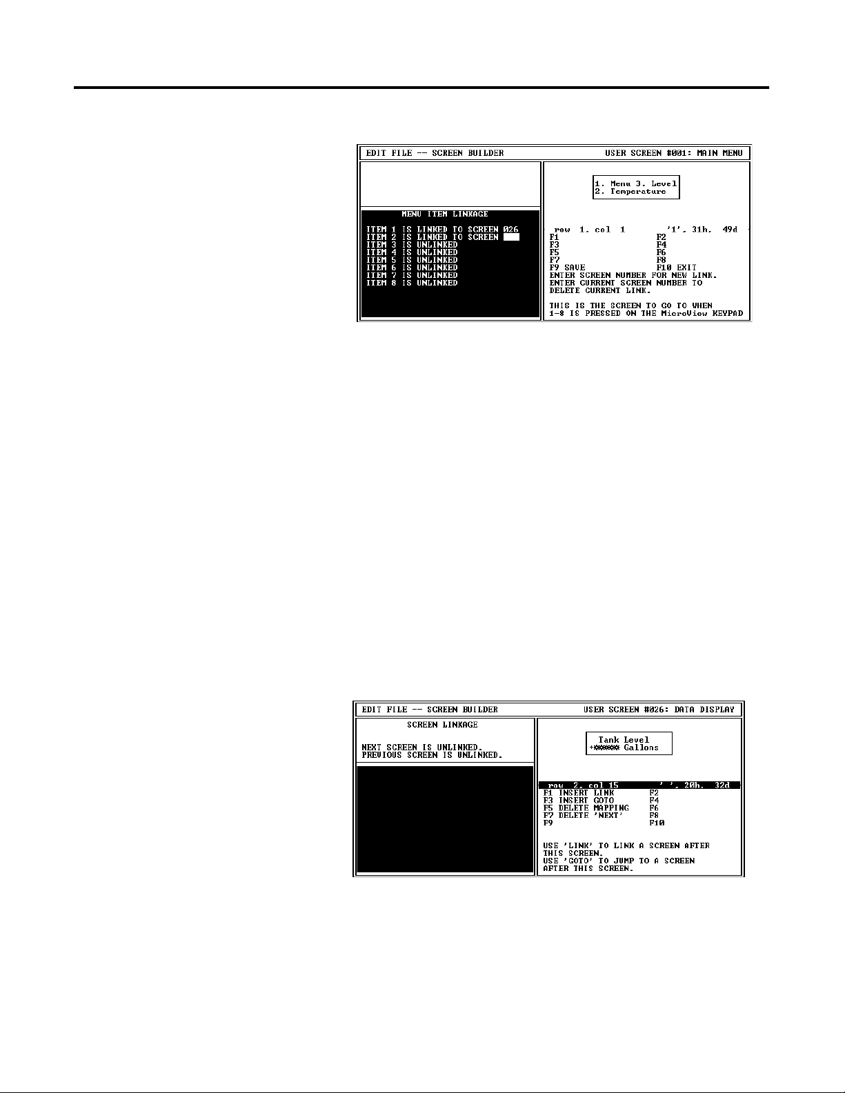
Linking Menu and Application Screens 11-5
3. Enter the screen # you want linked to numeric entry key [1] and
press [Return].
You are prompted to enter the screen linked to the MicroView
numeric key [2].
4. Continue entering the screen links for up to eight MicroView
numeric entry keys.
Linking Example
5. Press [F9] to save the menu edits.
The following example shows how to create one way or bidirectional
screen links.
To link application screens:
1. Open the screen you want to link. In this example, we are
linking screen #26 (data display) to screen #33 (data entry
screen).
Publication 2707-PM002B-EN-P
Page 78

11-6 Linking Menu and Application Screens
2. Press [F3] to select the MAP Screen function.
The current screen links are displayed along with the screen
linking function key operation.
3. Press [F1] to create a bidirectional link (operator can move
between screens) or [F3] to create a Goto (one way link, this
screen to specified screen).
You are prompted to enter a screen number.
INSERT SCREEN LINKAGE
SCREEN TO LINK TO:
33
4. Enter a screen number (in this example, screen #33) and press
[Return]. The screen link is shown in the Screen Linkage
description.
SCREEN LINKAGE
NEXT SCREEN IS SCREEN 33.
PREVIOUS SCREEN IS UNLINKED.
5. Press [F9] to save the screen edits.
When you open the screen that was just linked (screen #33), the
Screen Linkage description will show that there is now a
previous screen link to that screen.
SCREEN LINKAGE
NEXT SCREEN IS UNLINKED.
PREVIOUS SCREEN IS SCREEN 26.
Publication 2707-PM002B-EN-P
Page 79

Chapter
Entering MicroView Configuration Data
12
Chapter Objectives
Configuration Parameters
This chapter describes how to set the configuration parameters of the
MicroView.
Section Page
Configuration Parameters 12-1
Accessing Configuration Data 12-2
Update Interval 12-3
MicroView Advisor 12-4
Advisor Operation 12-5
Setting Master Security Code 12-6
Special Security Screen 12-7
MicroLogix Hardware Parameters 12-9
The following configuration parameters can be set. These parameters
are downloaded with the application and override any settings that
are currently used by the MicroView.
Parameter Description
Update Interval Defines the rate at which the screen display is updated.
MicroView Advisor Assign advisor register data allowing screen changes by a
controller.
Set Master Security Code Sets the master security code allowing an operator access
to security screens and codes.
Special Security Screen Restricts access to the Mode Menu of the MicroView to
prevent unauthorized access to controller functions.
PLC Hardware Parameters Defines the communication parameters between a
controller and the MicroView.
1 Publication 2707-PM002B-EN-P
Page 80

12-2 Entering MicroView Configuration Data
Accessing Configuration Data
The following shows how to access MicroView configuration data.
1. Select Edit Program File from the Opening menu.
You are prompted for a file name.
2. Enter the file name of the application.
The Edit File - Option Selection menu displays.
3. Select MicroView Configuration Data.
The Configuration - Option Selection menu displays.
Publication 2707-PM002B-EN-P
4. Select the configuration item you want to modify. Refer to the
appropriate section in this chapter for additional information.
Page 81

Entering MicroView Configuration Data 12-3
Update Interval
The update interval specifies the display update rate of the MicroView.
The Update Interval is the period of time between read and write
requests to the controller. This is not the rate at which data is read
from or written to a controller.
When you select Update Interval from the Configuration – Option
Selection menu, the following is displayed:
To assign a new update interval, enter a valid number from 0.05 to
12.50 seconds in any increment of 0.05 seconds and press [Return].
To save the new update interval, press [Esc]. You are then returned to
the Configuration – Option Selection menu.
Publication 2707-PM002B-EN-P
Page 82

12-4 Entering MicroView Configuration Data
MicroView Advisor
The Advisor function allows screen changes to be made by the logic
controller. The advisor consists of a controller address monitored by
the MicroView. When the advisor address contains a screen number,
the corresponding screen is displayed.
When you select MicroView Advisor from the Configuration – Option
Selection menu, the following is displayed:
The MicroView Advisor consists of six items:
Item Purpose
Screen Read
Register Number
ACK/NAK Write
Register Number
ACK Bit* The bit number within the ACK/NAK write
ACK/NAK Bit Polarity Defines the polarity (0 or 1) ACK/NAK bits:
Screen Write Enable
Screen Write
Register Number
* NAK bit is always the next sequential bit after the ACK bit.
** If Mode Menu is the current screen, the MicroView assigns it to screen number 255.
**
The controller address (16 bit) that the
MicroView reads for the current screen number.
The controller address (16 bit or bit type) that
contains the ACK
and NAK bits which are written to and monitored
by the MicroView
and controller. The write register is updated at
the Update Interval not the Advisor update rate.
register that will be used as an
acknowledgement bit. If a bit type address was
assigned for the write register, this field will be
filled in using the bit address specified. ACK/
NAK bits are used only to indicate that the
MicroView has received a message.
When set to 1, a value of 1 for the ACK bit
indicates a valid screen and a value of 1 for the
NAK bit indicates an invalid number.
When set to 0, a value of 0 for the ACK bit
indicates a valid screen and a value of 0 for the
NAK bit indicates an invalid number.
When enabled, the MicroView writes the current
screen number to the controller.
The controller address that is written by the
MicroView when screen write is enabled. The
MicroView writes the current screen number in
this register.
Publication 2707-PM002B-EN-P
Page 83

Entering MicroView Configuration Data 12-5
Advisor Operation
The following shows how the Advisor function operates. The
controller program must reset the ACK and NAK bits after writing a
screen number.
1. MicroLogix Controller writes screen number to assigned Read Register.
4. Controller monitoring ACK bit
clears ACK/NAK bits for next screen
number.
3. MicroView writes Advisor Write
Register ACK bit indicating that the
screen display was changed. Or wrties
NAK bit if an invalid screen was read.
2. MicroView reads Advisor Read
Register and displays corresponding
screen (if valid).
If the controller sends an invalid screen number (not a programmed
screen) the MicroView writes the write register NAK bit (always next
sequential bit following ACK bit). The NAK bit indicates to the
controller that the screen number is incorrect. The master security
code is used by an operator to access and/or change the security
codes of the security screens.
Publication 2707-PM002B-EN-P
Page 84

12-6 Entering MicroView Configuration Data
Setting Master Security Code
When you select Master Code from the Configuration - Option
Selection menu, the following is displayed:
Enter a new security code. There are two codes that perform special
functions:
• 00000000 disables the security function. This allows an
operator to enter any number as a valid access code.
• 99999999 disables the master security code(s). When used,
only the security code(s) assigned to individual screens are
valid. Use this code when you do not want to provide an
operator the ability to override or change security codes for
security screens.
The security code must be an 8 digit number, if you enter less than 8
digits, the remaining values are set to 0. The operator must enter all
eight numbers (including zeroes) for a valid code.
To save the new security code, press [Esc]. You are returned to the
Configuration - Option Selection menu.
ATTENTION
Keep a record of the Master Security Code. If you or
another user does not remember the Master Security
Code, the unit is disabled. You must return the unit
to the factory for repair.
!
Publication 2707-PM002B-EN-P
Page 85

Entering MicroView Configuration Data 12-7
Special Security Screen
The special security screen restricts access to the MicroView Mode
Menu. The MicroView Mode Menu allows an operator to directly
access controller data files and other controller functions. Providing a
security screen protects against unintended use of these functions. If
you don’t provide a special security screen, the Mode Menu is
available to any operator when they press [Mode] on the MicroView.
When you select Special Security Screen from the Configuration –
Option Selection menu, the first security screen is displayed:
To enter new security codes:
1. Enter an eight digit code. Press [Return] to advance to the next
security code. Enter up to three eight digit codes.
TIP
2. Press [F9] to save the new security codes and advance to the
next screen. If you do not wish to edit the security message,
Press [Esc] to exit the Special Security Screen. You are returned
to the Configuration - Option.
Use a question mark ? to specify a wild card
character. A wild card character matches with
any character input by the operator.
Publication 2707-PM002B-EN-P
Page 86

12-8 Entering MicroView Configuration Data
To edit the screen text:
You can edit the screen text from the second security screen. The
default text is shown in the example.
1. Press [F7] to clear the display window.
2. Enter the new message of up to 21 characters.
3. Press [F9] to save the new message.
4. Press [Esc] to exit the Special Security Screen You are returned
to the Configuration – Option Selection menu.
IMPORTANT
You cannot link the Special Security Screen. This
screen only restricts access to the Mode Menu and is
not assigned a screen number.
IMPORTANT
The security screen protects against unauthorized
entry into the (MODE MENU) of the MicroView.
Keep a record of all security codes used. If the user
forgets the security code and the DPS application
program is not available, there will be no way for the
user to place the MicroView into the program mode
in order to change or update an application.
Publication 2707-PM002B-EN-P
Page 87

Entering MicroView Configuration Data 12-9
MicroLogix Hardware Parameters
When using DF1 protocols, you must specify the operating parameters
that allow the MicroView to communicate with the controller. The
MicroView settings must match the settings of the controller.
When you select PLC Hardware Parameters from the Configuration Option Selection menu, the following is displayed:
Hardware
Parameter
Purpose
Com Port Setup Defines the baud rate used for communication with the
controller.
Advisor Update Rate Sets the rate at which the MicroView reads the advisor
register.
To save the new hardware parameters, press [F9]. To exit the screen,
press [Esc]. You are returned to the Configuration - Option Selection
menu.
Publication 2707-PM002B-EN-P
Page 88

12-10 Entering MicroView Configuration Data
Com Port Setup
Selecting Com Port Setup displays:
The Communications Port parameters have the following default
values for the MicroView:
Baud Rate: 9600
Parity: None
Data Bits: 8
Baud Rate
Default is 9600 baud. Baud rate options are 19200, 9600, 2400, 1200,
and 300.
Parity
Parity of the MicroView’s communications port is fixed at (None) and
it can not be changed.
Data Bits
Defines the data length. The number of data bits of MicroView’s
communication port is fixed at eight bits.
Publication 2707-PM002B-EN-P
Page 89

Entering MicroView Configuration Data 12-11
If you wish to change the baud rate of the MicroView, press [Return] to
display the second screen.
Select a baud rate that matches your controller.
To save the new Baud Rate, press [Esc]. You are returned to the PLC
Hardware Parameter - Option Selection menu.
Publication 2707-PM002B-EN-P
Page 90

12-12 Entering MicroView Configuration Data
Advisor Update Rate
Selecting Advisor Update Rate from the PLC Hardware Parameters –
Option Selection menu, displays the following:
The Advisor Update Rate is the periodic rate at which the MicroView
scans the Advisor register. For example a rate of 2.00 means the
MicroView reads the advisor register once every 2 seconds.
To assign a new Advisor Update Rate, enter a valid decimal number
and press [Return]. The valid range is from 1 to 12.5 seconds. The
default is 2 seconds. Entries are rounded up to the next higher 0.1
second.
To save the new Advisor Update Rate, press [Esc]. You are returned to
the PLC Hardware Parameter - Option Selection menu.
Note: Because the advisor adds to the network communication
traffic, the rate should be set to the highest possible value that is
acceptable for your application.
Publication 2707-PM002B-EN-P
Page 91

MicroView Function Key Builder
Chapter
13
Chapter Objectives
Function Key Options
This chapter describes how to use the Function Key Builder to assign
screen selection or bit write operations to function keys. The chapter
contains these sections:
Section Page
Function Key Options 13-1
Bit Write Mode 13-3
Function Key Builder 13-4
Linking Screens to Function Keys 13-5
Assigning Bit Write Functions 13-6
You can link the MicroView function keys, F1 and F2, to the following
screens depending upon whether or not Auto Return is enabled.
Auto Return Enabled? Function keys can be assigned to these screens:
Yes Data Display, Data Entry, Recipe
No Menu, Sub-Menu, Data Display, Data Entry, Security,
Recipe
Pressing an assigned function key displays the function key number
for approximately 0.5 seconds and then the assigned screen. There
are two function key modes:
• Auto Return
• Continue
1 Publication 2707-PM002B-EN-P
Page 92

13-2 MicroView Function Key Builder
Auto Return
Auto return function keys return to the initial display after the linked
screen is executed. For example, assume that an application is
displaying screen #6 and an auto return function key F2 is linked to a
recipe screen #10. When F2 is pressed, the recipe screen #10 is
displayed. After the operator downloads a new recipe on screen #10,
the initial screen #6 will be again displayed.
The following table describes when the return to the initial screen
occurs.
Function Key Linked To: Returns to Initial Screen After:
Data Display Screen
Data Entry Screen A value is entered or
Recipe Screen Recipe data is downloaded or
* [PREV] and [NEXT] abort the operation.
[ ], [PREV] or [NEXT] keys are pressed
[PREV] or [NEXT] keys are pressed *
[PREV], or [NEXT] keys are pressed *
Continue
Continue function keys do not return to the initial display but remain
at the linked screen. For example, assume that an application is
displaying screen #3 and a continue function key F1 is linked to a data
entry screen #5. When F1 is pressed, the data entry screen #5 is
displayed. The application continues from screen #5.
Publication 2707-PM002B-EN-P
Page 93

MicroView Function Key Builder 13-3
Bit Write Mode
The function keys of the MicroView can also set or clear bits in the
logic controller. The bit write mode may be enabled with or without
screen links being assigned to the same function keys (if bit write is
enabled, both function keys will write to the corresponding registers).
The function keys are assigned to 2 contiguous 16 bit addresses such
as N7:20 and N7:21.
Depending upon how a bit write is configured (clear or set), a
function key will either:
• send the corresponding value (F1 = 1, F2 = 2)
• clear the register
The following chart shows the set and clear values for each function
key. The register location for F1 is specified on the Function Key
Builder screen. The remaining function key is automatically assigned
to the next consecutive register.
MicroView
Function Key
F1 00000000 00000001 00000000 00000000 1
Set Value Clear Value
Register
Location
F2 00000000 00000010 00000000 00000000 2
TIP
The entire word register (16 bits) is written when a
bit write is initiated. Bit write does not change
individual bits.
If a function key is used for bit write mode as well as screen
navigation, the bit pattern will not be written if the MicroView cannot
go to the mapped screen.
Publication 2707-PM002B-EN-P
Page 94

13-4 MicroView Function Key Builder
Function Key Builder
The screen for assigning MicroView function key options is shown
below:
Function Key Builder Function Keys
Function
Key
[F1] PREV SCREEN Displays next programmed screen in display
Designation Function
window. Use this display as a reference when
assigning screen numbers to function keys.
[F2] NEXT SCREEN Displays previous programmed screen in display
window. Use this display as a reference when
assigning screen numbers to function keys.
[F5] BIT WRITE REG Prompts you for a base register location.
[F7] CLEAR F KEYS Clears all screen and bit write mode operations
assigned to the function keys.
[F9] SAVE Saves the application without exiting the Function
Key Builder screen.
[F10] EXIT Prompts you to save the application to the current
file and exits the DPS software.
Publication 2707-PM002B-EN-P
Page 95

MicroView Function Key Builder 13-5
Linking Screens to Function Keys
You can link function keys [F1] and [F2] to individual screens.
To link screens to function keys:
1. At the Opening menu select Edit Program File and enter a file
name.
The Edit File - Option Selection menu is displayed.
2. Select Function Key Builder.
The Function Key Builder screen appears.
3. Use the arrow keys to highlight the function key you want to
assign.
4. Enter a screen number for the function key and press [Return].
To see the screen you are assigning, press [F1] and [F2].
You are prompted if you want the key to auto return.
5. Enter [Y] for Auto Return Mode or [N] for Continue Mode and
press [Return].
6. Assign the other function key using the same procedure. To
assign bit write mode functions, refer to the next section.
7. Press [F9] to save the screen.
Publication 2707-PM002B-EN-P
Page 96

13-6 MicroView Function Key Builder
Assigning Bit Write Functions
To assign bit write mode functions:
1. Open the Function Key Builder screen, refer to previous section.
2. Press [F5] to assign the bit write mode register.
You are prompted to enter a base register.
Publication 2707-PM002B-EN-P
3. Enter the base register number (for function key F1) and press
[Return], the next register will automatically be assigned to
function key F2.
You are prompted to clear or set a bit when the operator presses
the function key.
Page 97

MicroView Function Key Builder 13-7
4. Enter [1] or [0] and press [Return]. Press [Esc] when done.
The function key register assignments are displayed (partial
screen shown).
Function Key
Register Assignments
5. Press [F9] to save the screen.
Publication 2707-PM002B-EN-P
Page 98

13-8 MicroView Function Key Builder
Publication 2707-PM002B-EN-P
Page 99

Chapter
Transferring / Printing Application Files
14
Chapter Objectives
Program Mode Setting
This chapter describes how to transfer application files between a
MicroView and a personal computer. Also provided is a description
of how to print out an application file.
Section Page
Program Mode Setting 14-1
Communication Cables 14-1
Power Supply 14-1
Computer Setup 14-1
Downloading an Application 14-2
Uploading an Application 14-5
Printing Application Files 14-8
Before you can upload or download an application, you must set the
MicroView to the Program Mode. Refer to the MicroView User Manual
for information on how to access the Program Mode.
Communication Cables
Power Supply
Computer Setup
1 Publication 2707-PM002B-EN-P
You will need a programming cable, Catalog No. 2707-NC8. If you
need to construct your own cable. refer to the cable diagrams
provided in the MicroView User Manual.
You will also need a MicroView Power Supply (Catalog No.
2707-PS120 or 2707-PS220) to power the MicroView during the
program transfer.
Upload and download functions are initiated from a personal
computer running the programming software DPS. All transfer
functions occur at 9600 baud.
After the transfer is complete, the MicroView baud rate is set to the
parameters defined by the application program residing in the
MicroView.
Page 100

14-2 Transferring / Printing Application Files
Downloading an Application
This section shows how to download an application from a computer
running DPS software to the MicroView.
1. Apply power to the MicroView and set the MicroView to the
Program Mode.
• Press the[MODE] key
• [3] for Special,
• [3] for Program,
• [1] for Upload (Download).
2. The following message will appear in the window of the
MicroView.
If you do not see this message, consult the MicroView User
Manual (Publication No. 2707-UM005B-EN-P) for information on
how to access the Program Mode.
Programming Mode
“MENU” to Exit
3. On your computer, move to the /MDPS subdirectory where the
software resides.
C:\MDPS>
4. Type dps and press [Return] to start the program.
C:\MDPS>dps [Return]
5. Specify whether you are using a color monitor. Enter [Y] or [N].
You will not see this prompt if a monitor was selected during
installation.
The startup screen displays:
6. Press any key to continue.
Publication 2707-PM002B-EN-P
 Loading...