

Page 1
Allen-Bradley
DTAM
Programming
Programming
Software
Catalog No. 2707-NP
Manual
Page 2

Important User Information
Solid state equipment has operational characteristics differing from those of
electromechanical equipment. “Safety Guidelines for the Application,
Installation and Maintenance of Solid State Controls” (Publication SGI-1.1)
describes some important differences between solid state equipment and
hard–wired electromechanical devices. Because of this difference, and also
because of the wide variety of uses for solid state equipment, all persons
responsible for applying this equipment must satisfy themselves that each
intended application of this equipment is acceptable.
In no event will the Allen-Bradley Company be responsible or liable for
indirect or consequential damages resulting from the use or application of
this equipment.
The examples and diagrams in this manual are included solely for illustrative
purposes. Because of the many variables and requirements associated with
any particular installation, the Allen-Bradley Company cannot assume
responsibility or liability for actual use based on the examples and diagrams.
No patent liability is assumed by Allen-Bradley Company with respect to use
of information, circuits, equipment, or software described in this manual.
Reproduction of the contents of this manual, in whole or in part, without
written permission of the Allen-Bradley Company is prohibited.
Throughout this manual we use notes to make you aware of safety
considerations.
ATTENTION: Identifies information about practices or
circumstances that can lead to personal injury or death, property
!
damage, or economic loss.
Attentions help you:
• identify a hazard
• avoid the hazard
• recognize the consequences
Important: Identifies information that is especially important for successful
application and understanding of the product.
PLC and PLC–5 are registered trademarks of Allen-Bradley Company, Inc.
SLC, DTAM Plus, and DTAM Micro are trademarks of Allen-Bradley Company, Inc.
IBM is a registered trademark of International Business Machines, Incorporated.
Page 3

Table of Contents
DT AM Programming Software
User Manual
Using this Manual
Installing / Running
DTAM Programming
Software
Chapter 1
Objectives 1–1. . . . . . . . . . . . . . . . . . . . . . . . . . . . . . . . . . . . . . . . . . . . . . . . .
Contents 1–1. . . . . . . . . . . . . . . . . . . . . . . . . . . . . . . . . . . . . . . . . . . . . . . . . .
Intended Audience 1–2. . . . . . . . . . . . . . . . . . . . . . . . . . . . . . . . . . . . . . . . . . .
Conventions 1–3. . . . . . . . . . . . . . . . . . . . . . . . . . . . . . . . . . . . . . . . . . . . . . .
Related Publications 1–4. . . . . . . . . . . . . . . . . . . . . . . . . . . . . . . . . . . . . . . . .
Chapter 2
Chapter Objectives 2–1. . . . . . . . . . . . . . . . . . . . . . . . . . . . . . . . . . . . . . . . . .
Introduction to DTAM Programming Software 2–1. . . . . . . . . . . . . . . . . . . . . . . .
Software Requirements 2–1. . . . . . . . . . . . . . . . . . . . . . . . . . . . . . . . . . . . . . .
Firmware Compatibility 2–1. . . . . . . . . . . . . . . . . . . . . . . . . . . . . . . . . . . . . . . .
Performing Firmware Upgrade with Older Software Versions 2–2. . . . . . . . . . . . .
System Requirements 2–2. . . . . . . . . . . . . . . . . . . . . . . . . . . . . . . . . . . . . . . .
Communication Cables 2–2. . . . . . . . . . . . . . . . . . . . . . . . . . . . . . . . . . . . . . .
Making a Backup Copy 2–2. . . . . . . . . . . . . . . . . . . . . . . . . . . . . . . . . . . . . . .
Installation Files 2–2. . . . . . . . . . . . . . . . . . . . . . . . . . . . . . . . . . . . . . . . . . . . .
Installing DT AM Programming Software 2–3. . . . . . . . . . . . . . . . . . . . . . . . . . . .
Running DPS 2–6. . . . . . . . . . . . . . . . . . . . . . . . . . . . . . . . . . . . . . . . . . . . . .
Menu Conventions 2–8. . . . . . . . . . . . . . . . . . . . . . . . . . . . . . . . . . . . . . . . . . .
Screen Building Conventions 2–9. . . . . . . . . . . . . . . . . . . . . . . . . . . . . . . . . . .
Cursor Status Line 2–10. . . . . . . . . . . . . . . . . . . . . . . . . . . . . . . . . . . . . . . . . . .
Moving Around Screens 2–10. . . . . . . . . . . . . . . . . . . . . . . . . . . . . . . . . . . . . . .
Linking Application Screens 2–10. . . . . . . . . . . . . . . . . . . . . . . . . . . . . . . . . . . .
Designing DTAM Plus and
DTAM Micro Applications
Creating or Editing an
Application File
Chapter 3
Objectives 3–1. . . . . . . . . . . . . . . . . . . . . . . . . . . . . . . . . . . . . . . . . . . . . . . . .
DT AM Plus / DTAM Micro Comparison 3–2. . . . . . . . . . . . . . . . . . . . . . . . . . . .
DT AM Plus / DTAM Micro File Types 3–3. . . . . . . . . . . . . . . . . . . . . . . . . . . . . .
Screen Types and Data Formats 3–4. . . . . . . . . . . . . . . . . . . . . . . . . . . . . . . . .
PLC Data Formats 3–5. . . . . . . . . . . . . . . . . . . . . . . . . . . . . . . . . . . . . . . . .
SLC Data Formats 3–5. . . . . . . . . . . . . . . . . . . . . . . . . . . . . . . . . . . . . . . . .
Data Scaling 3–6. . . . . . . . . . . . . . . . . . . . . . . . . . . . . . . . . . . . . . . . . . . . . . .
Application Example 3–8. . . . . . . . . . . . . . . . . . . . . . . . . . . . . . . . . . . . . . . . .
Example Application Description 3–9. . . . . . . . . . . . . . . . . . . . . . . . . . . . . . . . .
Designing an Application 3–10. . . . . . . . . . . . . . . . . . . . . . . . . . . . . . . . . . . . . .
Chapter 4
Chapter Objectives 4–1. . . . . . . . . . . . . . . . . . . . . . . . . . . . . . . . . . . . . . . . . .
Opening Menu 4–1. . . . . . . . . . . . . . . . . . . . . . . . . . . . . . . . . . . . . . . . . . . . . .
Edit Application File 4–2. . . . . . . . . . . . . . . . . . . . . . . . . . . . . . . . . . . . . . . . . .
Save Application File 4–4. . . . . . . . . . . . . . . . . . . . . . . . . . . . . . . . . . . . . . . . .
i
Page 4

Table of Contents
DT AM Programming Software
User Manual
Using Screen Builder
Creating Menu and
Sub-Menu Screens
Chapter 5
Chapter Objectives 5–1. . . . . . . . . . . . . . . . . . . . . . . . . . . . . . . . . . . . . . . . . .
Screen Builder 5–1. . . . . . . . . . . . . . . . . . . . . . . . . . . . . . . . . . . . . . . . . . . . . .
Accessing Screen Types 5–2. . . . . . . . . . . . . . . . . . . . . . . . . . . . . . . . . . . . . .
Editing Screen Displays 5–4. . . . . . . . . . . . . . . . . . . . . . . . . . . . . . . . . . . . . . .
Copying Screens 5–5. . . . . . . . . . . . . . . . . . . . . . . . . . . . . . . . . . . . . . . . . . . .
Selecting Other Screens 5–6. . . . . . . . . . . . . . . . . . . . . . . . . . . . . . . . . . . . . . .
Clearing Screens 5–7. . . . . . . . . . . . . . . . . . . . . . . . . . . . . . . . . . . . . . . . . . . .
Inserting the Time or Date 5–8. . . . . . . . . . . . . . . . . . . . . . . . . . . . . . . . . . . . .
Exiting Screen Builder 5–9. . . . . . . . . . . . . . . . . . . . . . . . . . . . . . . . . . . . . . . .
Chapter 6
Chapter Objectives 6–1. . . . . . . . . . . . . . . . . . . . . . . . . . . . . . . . . . . . . . . . . .
Menu Screens 6–1. . . . . . . . . . . . . . . . . . . . . . . . . . . . . . . . . . . . . . . . . . . . . .
Main Menu Screens 6–1. . . . . . . . . . . . . . . . . . . . . . . . . . . . . . . . . . . . . . . .
Sub-Menu Screens 6–1. . . . . . . . . . . . . . . . . . . . . . . . . . . . . . . . . . . . . . . .
Building a Menu 6–2. . . . . . . . . . . . . . . . . . . . . . . . . . . . . . . . . . . . . . . . . . . . .
Main Menu and Sub-Menu Screen Builder 6–3. . . . . . . . . . . . . . . . . . . . . . . . . .
Creating a Menu Screen 6–4. . . . . . . . . . . . . . . . . . . . . . . . . . . . . . . . . . . . . . .
Creating Data
Display Screens
Creating Data
Entry Screens
Chapter 7
Chapter Objectives 7–1. . . . . . . . . . . . . . . . . . . . . . . . . . . . . . . . . . . . . . . . . .
Data Displays 7–1. . . . . . . . . . . . . . . . . . . . . . . . . . . . . . . . . . . . . . . . . . . . . .
Scaling 7–1. . . . . . . . . . . . . . . . . . . . . . . . . . . . . . . . . . . . . . . . . . . . . . . . . . .
Data Display Screen Builder 7–2. . . . . . . . . . . . . . . . . . . . . . . . . . . . . . . . . . . .
Creating a Display Screen 7–3. . . . . . . . . . . . . . . . . . . . . . . . . . . . . . . . . . . . .
Display Register Format Selections 7–5. . . . . . . . . . . . . . . . . . . . . . . . . . . . . . .
Chapter 8
Chapter Objectives 8–1. . . . . . . . . . . . . . . . . . . . . . . . . . . . . . . . . . . . . . . . . .
Data Entry Screens 8–1. . . . . . . . . . . . . . . . . . . . . . . . . . . . . . . . . . . . . . . . . .
Scaling 8–1. . . . . . . . . . . . . . . . . . . . . . . . . . . . . . . . . . . . . . . . . . . . . . . . . . .
Data Entry Screen Builder 8–2. . . . . . . . . . . . . . . . . . . . . . . . . . . . . . . . . . . . .
Creating a Data Entry Screen 8–3. . . . . . . . . . . . . . . . . . . . . . . . . . . . . . . . . . .
Data Entry Register Format Selections 8–6. . . . . . . . . . . . . . . . . . . . . . . . . . . .
ii
Page 5

Table of Contents
DT AM Programming Software
User Manual
Creating Security Screens
Creating Recipe Screens
Creating Bar
Graph Screens
Chapter 9
Chapter Objectives 9–1. . . . . . . . . . . . . . . . . . . . . . . . . . . . . . . . . . . . . . . . . .
Security Screens 9–1. . . . . . . . . . . . . . . . . . . . . . . . . . . . . . . . . . . . . . . . . . . .
Security Screen Builder 9–2. . . . . . . . . . . . . . . . . . . . . . . . . . . . . . . . . . . . . . .
Creating a Security Screen 9–3. . . . . . . . . . . . . . . . . . . . . . . . . . . . . . . . . . . . .
Chapter 10
Chapter Objectives 10–1. . . . . . . . . . . . . . . . . . . . . . . . . . . . . . . . . . . . . . . . . .
Recipe Screens 10–1. . . . . . . . . . . . . . . . . . . . . . . . . . . . . . . . . . . . . . . . . . . . .
Recipe Screen Builder 10–2. . . . . . . . . . . . . . . . . . . . . . . . . . . . . . . . . . . . . . . .
Creating a Recipe Screen 10–3. . . . . . . . . . . . . . . . . . . . . . . . . . . . . . . . . . . . . .
Chapter 11
Chapter Objectives 1 1–1. . . . . . . . . . . . . . . . . . . . . . . . . . . . . . . . . . . . . . . . . .
Bar Graph Screens 11–1. . . . . . . . . . . . . . . . . . . . . . . . . . . . . . . . . . . . . . . . . .
Bar Graph Screen Builder 11–2. . . . . . . . . . . . . . . . . . . . . . . . . . . . . . . . . . . . . .
Graph Display Range 11–3. . . . . . . . . . . . . . . . . . . . . . . . . . . . . . . . . . . . . . . . .
Creating a Bar Graph Screen 1 1–4. . . . . . . . . . . . . . . . . . . . . . . . . . . . . . . . . . .
Bar Graph Register Format Selections 1 1–6. . . . . . . . . . . . . . . . . . . . . . . . . . . . .
Linking Menu and
Application Screens
Creating Alarm Screens
Chapter 12
Chapter Objectives 12–1. . . . . . . . . . . . . . . . . . . . . . . . . . . . . . . . . . . . . . . . . .
Linking Application Screens 12–1. . . . . . . . . . . . . . . . . . . . . . . . . . . . . . . . . . . .
Linking Menu Screens 12–2. . . . . . . . . . . . . . . . . . . . . . . . . . . . . . . . . . . . . . . .
Screen Linking Guidelines 12–2. . . . . . . . . . . . . . . . . . . . . . . . . . . . . . . . . . . . .
Application Screen Linking Function Keys 12–3. . . . . . . . . . . . . . . . . . . . . . . . . .
Menu and Sub-Menu Linkage Display 12–3. . . . . . . . . . . . . . . . . . . . . . . . . . . . .
Linking a Menu 12–4. . . . . . . . . . . . . . . . . . . . . . . . . . . . . . . . . . . . . . . . . . . . .
Linking Example 12–5. . . . . . . . . . . . . . . . . . . . . . . . . . . . . . . . . . . . . . . . . . . .
Chapter 13
Chapter Objectives 13–1. . . . . . . . . . . . . . . . . . . . . . . . . . . . . . . . . . . . . . . . . .
Alarm Screens 13–1. . . . . . . . . . . . . . . . . . . . . . . . . . . . . . . . . . . . . . . . . . . . . .
Alarm Screen Builder 13–3. . . . . . . . . . . . . . . . . . . . . . . . . . . . . . . . . . . . . . . . .
Creating an Alarm Screen 13–4. . . . . . . . . . . . . . . . . . . . . . . . . . . . . . . . . . . . .
iii
Page 6

Table of Contents
DT AM Programming Software
User Manual
Entering DTAM
Configuration Data
Chapter 14
Chapter Objectives 14–1. . . . . . . . . . . . . . . . . . . . . . . . . . . . . . . . . . . . . . . . . .
Configuration Parameters 14–1. . . . . . . . . . . . . . . . . . . . . . . . . . . . . . . . . . . . . .
Accessing Configuration Data 14–2. . . . . . . . . . . . . . . . . . . . . . . . . . . . . . . . . . .
Update Interval 14–3. . . . . . . . . . . . . . . . . . . . . . . . . . . . . . . . . . . . . . . . . . . . .
DT AM Advisor 14–4. . . . . . . . . . . . . . . . . . . . . . . . . . . . . . . . . . . . . . . . . . . . . .
Advisor Operation 14–5. . . . . . . . . . . . . . . . . . . . . . . . . . . . . . . . . . . . . . . . .
Time Synchronization 14–6. . . . . . . . . . . . . . . . . . . . . . . . . . . . . . . . . . . . . . . . .
Setting Master Security Code 14–8. . . . . . . . . . . . . . . . . . . . . . . . . . . . . . . . . . .
Special Security Screen 14–9. . . . . . . . . . . . . . . . . . . . . . . . . . . . . . . . . . . . . .
Printer Port Parameters 14–10. . . . . . . . . . . . . . . . . . . . . . . . . . . . . . . . . . . . . . .
SLC Hardware Parameters 14–11. . . . . . . . . . . . . . . . . . . . . . . . . . . . . . . . . . . .
SLC Com Port Setup 14–12. . . . . . . . . . . . . . . . . . . . . . . . . . . . . . . . . . . . . . .
SLC 500 Slot Configuration 14–13. . . . . . . . . . . . . . . . . . . . . . . . . . . . . . . . . .
Max Node Address 14–13. . . . . . . . . . . . . . . . . . . . . . . . . . . . . . . . . . . . . . . .
SLC 500 Node Address 14–14. . . . . . . . . . . . . . . . . . . . . . . . . . . . . . . . . . . . .
DT AM Node Address 14–14. . . . . . . . . . . . . . . . . . . . . . . . . . . . . . . . . . . . . .
Advisor Update Rate 14–15. . . . . . . . . . . . . . . . . . . . . . . . . . . . . . . . . . . . . . .
PLC Hardware Parameters 14–16. . . . . . . . . . . . . . . . . . . . . . . . . . . . . . . . . . . . .
PLC Com Port Setup 14–17. . . . . . . . . . . . . . . . . . . . . . . . . . . . . . . . . . . . . . .
RIO port Setup with Remote I/O Operating System 14–18. . . . . . . . . . . . . . . . . .
Com Port Setup with DevieNet Operating System 14–19. . . . . . . . . . . . . . . . . . .
Advisor Update Rate 14–20. . . . . . . . . . . . . . . . . . . . . . . . . . . . . . . . . . . . . . .
DTAM Plus
Background Monitor
DTAM Micro
Function Key Builder
Chapter 15
Chapter Objectives 15-1. . . . . . . . . . . . . . . . . . . . . . . . . . . . . . . . . . . . . . . . . .
Background Monitor 15-1. . . . . . . . . . . . . . . . . . . . . . . . . . . . . . . . . . . . . . . . . .
Background Monitor Screen 15-2. . . . . . . . . . . . . . . . . . . . . . . . . . . . . . . . . . . .
Creating a Background Monitor 15-3. . . . . . . . . . . . . . . . . . . . . . . . . . . . . . . . . .
Background Monitor Register Selections 15-5. . . . . . . . . . . . . . . . . . . . . . . . . . .
Chapter 16
Chapter Objectives 16–1. . . . . . . . . . . . . . . . . . . . . . . . . . . . . . . . . . . . . . . . . .
Function Key Options 16–1. . . . . . . . . . . . . . . . . . . . . . . . . . . . . . . . . . . . . . . . .
Bit Write Mode 16–2. . . . . . . . . . . . . . . . . . . . . . . . . . . . . . . . . . . . . . . . . . . . . .
Function Key Builder 16–3. . . . . . . . . . . . . . . . . . . . . . . . . . . . . . . . . . . . . . . . .
Linking Screens to Function Keys 16–4. . . . . . . . . . . . . . . . . . . . . . . . . . . . . . . .
Assigning Bit Write Functions 16–5. . . . . . . . . . . . . . . . . . . . . . . . . . . . . . . . . . .
iv
Page 7

Table of Contents
DT AM Programming Software
User Manual
DTAM Plus
Print Form Builder
DTAM Plus ASCII
Bar Code Input
Transferring / Printing
Application Files
Chapter 17
Chapter Objectives 17–1. . . . . . . . . . . . . . . . . . . . . . . . . . . . . . . . . . . . . . . . . .
Printer Form Builder 17–1. . . . . . . . . . . . . . . . . . . . . . . . . . . . . . . . . . . . . . . . . .
Printer Control 17–1. . . . . . . . . . . . . . . . . . . . . . . . . . . . . . . . . . . . . . . . . . . . . .
Print Form Builder Function Keys 17–2. . . . . . . . . . . . . . . . . . . . . . . . . . . . . . . .
Creating a Printer Form 17–3. . . . . . . . . . . . . . . . . . . . . . . . . . . . . . . . . . . . . . .
Print Forms 16 Bit Binary Data 17–6. . . . . . . . . . . . . . . . . . . . . . . . . . . . . . . . . .
Chapter 18
Chapter Objectives 18–1. . . . . . . . . . . . . . . . . . . . . . . . . . . . . . . . . . . . . . . . . .
ASCII Input 18–1. . . . . . . . . . . . . . . . . . . . . . . . . . . . . . . . . . . . . . . . . . . . . . . .
Allen-Bradley Bar Code Message Formats 18–1. . . . . . . . . . . . . . . . . . . . . . . . . .
Creating an ASCII Entry Display 18–2. . . . . . . . . . . . . . . . . . . . . . . . . . . . . . . . .
Entering Data with a Bar Code Scanner 18–3. . . . . . . . . . . . . . . . . . . . . . . . . . . .
Chapter 19
Chapter Objectives 19–1. . . . . . . . . . . . . . . . . . . . . . . . . . . . . . . . . . . . . . . . . .
Upload / Download DIP Switch Settings 19–1. . . . . . . . . . . . . . . . . . . . . . . . . . .
Communication Cables 19–1. . . . . . . . . . . . . . . . . . . . . . . . . . . . . . . . . . . . . . .
Computer Setup 19–1. . . . . . . . . . . . . . . . . . . . . . . . . . . . . . . . . . . . . . . . . . . .
Printer Setup 19–1. . . . . . . . . . . . . . . . . . . . . . . . . . . . . . . . . . . . . . . . . . . . . . .
Downloading an Application 19–2. . . . . . . . . . . . . . . . . . . . . . . . . . . . . . . . . . . .
Uploading an Application 19–6. . . . . . . . . . . . . . . . . . . . . . . . . . . . . . . . . . . . . .
Printing Application Files 19–9. . . . . . . . . . . . . . . . . . . . . . . . . . . . . . . . . . . . . .
Upgrading the
Operating System
ASCII Character Set
Application and
Screen Worksheets
PLC-5 Mnemonics in DPS
Chapter 20
Chapter Objectives 20–1. . . . . . . . . . . . . . . . . . . . . . . . . . . . . . . . . . . . . . . . . .
Upgrading the Operating System 20–1. . . . . . . . . . . . . . . . . . . . . . . . . . . . . . . .
Appendix A
ASCII Table A–1. . . . . . . . . . . . . . . . . . . . . . . . . . . . . . . . . . . . . . . . . . . . . . . .
How to Program Supported ASCII Characters A–1. . . . . . . . . . . . . . . . . . . . . . .
Appendix B
Application and Screen Worksheets B–1. . . . . . . . . . . . . . . . . . . . . . . . . . . . . .
Appendix C
v
Page 8

Table of Contents
DT AM Programming Software
User Manual
Data Formats
Appendix D
Data Formats D–1. . . . . . . . . . . . . . . . . . . . . . . . . . . . . . . . . . . . . . . . . . . . . .
Bit Format D–2. . . . . . . . . . . . . . . . . . . . . . . . . . . . . . . . . . . . . . . . . . . . . . .
16 Bit Signed Integer D–2. . . . . . . . . . . . . . . . . . . . . . . . . . . . . . . . . . . . . . .
16 Bit Unsigned Integer D–3. . . . . . . . . . . . . . . . . . . . . . . . . . . . . . . . . . . . .
16 Bit BCD D–3. . . . . . . . . . . . . . . . . . . . . . . . . . . . . . . . . . . . . . . . . . . . . .
16 Bit HEX (Hexadecimal) D–3. . . . . . . . . . . . . . . . . . . . . . . . . . . . . . . . . . .
32 Bit Unsigned Integer D–4. . . . . . . . . . . . . . . . . . . . . . . . . . . . . . . . . . . . .
32 Bit BCD (Binary Coded Decimal) D–4. . . . . . . . . . . . . . . . . . . . . . . . . . . .
32 Bit HEX (Hexadecimal) D–4. . . . . . . . . . . . . . . . . . . . . . . . . . . . . . . . . . .
32 Bit Floating Point (PLC Controllers Only) D–5. . . . . . . . . . . . . . . . . . . . . . .
DT AM Micro Floating Point Numbers D–5. . . . . . . . . . . . . . . . . . . . . . . . . . . .
ASCII D–8. . . . . . . . . . . . . . . . . . . . . . . . . . . . . . . . . . . . . . . . . . . . . . . . . .
vi
Page 9

Chapter
Objectives
Contents
A–B
1
Using this Manual
Read this chapter to familiarize yourself with the rest of the manual.
You will learn about:
• Contents of this manual
• Intended audience
• Conventions
• Related publications
The following table lists the contents of each chapter:
Chapter Title Purpose
1 Using this Manual
2
3
4
5 Using Screen Builder
6
7
8 Creating Data Entry Screens
9 Creating Security Screens
10 Creating Recipe Screens
11 Creating Bar Graph Screens
12
13 Creating Alarm Screens
Installing/Running DTAM
Programming Software
Designing DTAM Plus and
DTAM Micro Applications
Creating and Editing
an Application File
Creating Menu and
Sub-Menu Screens
Creating Data
Display Screens
Linking Menu and Application
Screens
Provides a brief overview of the manual
structure, intended use, and conventions.
Describes how to install DPS on your
computer. Basic software operating
functions are described.
Describes the differences and similarities
between DTAM Micro and DTAM Plus
applications.
Describes how to open, edit, and save
new or existing application files.
Describes how to use Screen Builder to
create application screens.
Describes how to create menu and
sub-menu displays.
Describes how to display the actual or
scaled contents of a controller address.
Describes how to create a screen that
allows an operator to write data to a
controller address.
Describes how to create screens that
restrict operator access to parts of an
application.
Describes how to create screens that
write data to multiple controller
addresses from a single screen.
Describes how to create a data display
using a bar graph.
Describes how to link all of the
application screens into a logical
sequence.
Describes how to create screens that
warn an operator of abnormal operating
conditions.
1–1
Page 10

Chapter 1
Using this Manual
Chapter
14 Entering Configuration Data
15
16
17
18 ASCII Bar Code Input
19
20
Appendix A ASCII Display Characters
Appendix B
Appendix C
Appendix D PLC-5 Mnemonics in DPS
Appendix E Data Formats
Index
DTAM Plus
Background Monitor
DTAM Micro
Function Key Builder
DTAM Plus
Printer Form Builder
Transferring / Printing
Application Files
Upgrading the Operating
System
Application and Screen
Worksheets
Using a BASIC Module
With An SLC
Title Purpose
Describes how to enter configuration
data that allows the DTAM to
communicate with a controller.
Describes how to monitor controller
addresses for displaying alarm or
generating printouts on the DTAM Plus.
Describes how to assign screen
navigation or bit write functions to the
DTAM Micro function keys.
Describes how to create a DTAM Plus
printer form.
Describes how to input data into a data
entry register using a bar code scanner.
Describes how to transfer applications
between a personal computer and the
DTAM Plus or DTAM Micro.
Describes how to upgrade the DTAM
Micro and DTAM Plus operating systems.
The character set supported by the
DTAM Micro and DTAM Plus.
Worksheets assist in the design of an
application and individual screens.
Describes how to use the SLC BASIC
module with a DTAM Plus AB BASIC
operating system.
Reference section for PLC mnemonic
codes used for addressing.
Description of the data formats used by
SLC and PLC controllers.
Intended Audience
1–2
The DTAM Programming Software does not require special programming
knowledge. It is menu driven and generates a DTAM Plus, DTAM Micro or
MicroView program based on your menu selections and data entries.
If you are creating an application for a DTAM Plus or Micro, you should be
familiar with the user manuals. Refer to related publications on page 1–4.
Page 11
Chapter 1
Using this Manual
Conventions
This manual uses the following conventions:
• Keys that you press on your personal computer keyboard are enclosed in
brackets [ ].
For example: [Esc] refers to the Escape key
• Keys that an operator would press on the DTAM Micro or DTAM Plus
are also enclosed in brackets but are bold [ ].
For example: [F1] refers to the F1 function key on the DTAM Micro.
• [Return] refers to the carriage return key of your computer keyboard.
This key may appear on your keyboard as [Enter] or [
].
• This manual describes how to use the DTAM programming software for
both DTAM Plus and DTAM Micro applications. DTAM Plus screens are
shown for most examples, these illustrations also apply to the DTAM
Micro unless noted.
DTAM Plus shown
but also applies to
DTAM Micro.
• DPS refers to DTAM Programing Software (Catalog No. 2707-NP, Series
J or later)
1–3
Page 12
Chapter 1
Using this Manual
Related Publications
The following publications may be required for additional reference.
DT AM Plus and DTAM Micro Publications
Publication / Catalog
Number
2707-800 DTAM Plus User Manual
2707-803 DTAM Micro User Manual
2707-802 Getting Started With the DTAM Plus
SLC Publications
Publication / Catalog
Number
1747-6.21
1747-6.2
1746-6.1
1746-6.2
1746-6.3
SLC 500 Fixed Hardware Style
Installation and Operation Manual
SLC 500 Modular Hardware Style
Installation and Operation Manual
SLC 500 BASIC Module
Design and Integration Manual
Development Software Programming Manual
Language Reference Manual
Title
Title
SLC 500 BASIC
SLC 500 BASIC
PLC-5 Publications
Publication / Catalog
Number
1785-6.2.1 1785 PLC-5 Programmable Controllers Design Manual
1785-6.1 PLC-5 Instruction Set Reference
1785-6.6.1
1785-7.1 PLC-5 Programmable Controllers Quick Reference
Title
PLC-5 Family Programmable Controllers Hardware
Installation Manual
1–4
Page 13

Chapter
Chapter Objectives
A–B
2
Installing / Running
DTAM Programming Software
This chapter describes how to install the DPS software. Menu and screen
conventions are also provided.
Section Page
Introduction to DTAM Programming Software 2–1
System Requirements 2–2
Communications Cable 2–2
Making a Backup Copy 2–2
Installation Files 2–2
Installing DTAM Programming Software 2–3
Running DPS 2–6
Menu Conventions 2–9
Screen Building Conventions 2–10
Cursor Status Line 2–11
Moving Around Screens 2–11
Linking Application Screens 2–11
Introduction to DTAM Programming Software
Software Requirements
Firmware Compatibility
The DTAM Programming Software (DPS) is a self-prompting, menu driven
package that allows you to create and edit applications for the DTAM Plus or
DTAM Micro operator terminals. DPS does not require any programming
knowledge.
DTAM Plus Series C and later versions require 2707-NP Programming
Software release 7.0 and later.
DTAM Micro Series C and later versions require 2707-NP Programming
Software release 8.0 and later.
Because of the hardware enhancements made to the DTAM Plus and DTAM
Micro products, a minimum level of firmware is required for these products
to operate with the programming software. Previous series of these products
have not been released with the newer firmware required. As a precaution:
You should upgrade the software for the DTAM Micro or DTAM
Plus to Version 9.0 or above.
2–1
Page 14

Chapter 2
Installing / Running
DTAM Programming Software
Performing Firmware Upgrade
with Older Software Versions
System Requirements
Communication Cables
The incompatibility between firmware and hardware causes the screen to go
blank and no communications with the SLC/PLC will occur. You must then
upgrade the firmware to the latest level available before the DTAM will
respond again.
Verify your computer is properly configured with the following:
• IBM PC/AT or 100% compatible
• 640K RAM (minimum)
• One or two diskette drives (720K minimum)
• One fixed (hard) disk drive recommended. Required if only one diskette
drive is present.
• DOS version 3.2 or later
• Serial communications port (COM1 or COM2)
RS-232C or RS-485
• Monochrome or color monitor (color monitor is recommended).
You need an upload/download cable (Catalog No. 2707-NC2) or (Catalog
No. 2707- NC5) to connect the computer to the DTAM Plus or DTAM Micro
communications port. If you have a DTAM Plus Remote I/O version with
only a printer port, you will need to use cable (Catalog No. 2707-NC2) with
a gender adapter. Refer to the DTAM Plus/Micro User Manuals for
download/upload cabling information.
Making a Backup Copy
Installation Files
2–2
Make a backup copy of the DTAM programming software diskette. Insert
the supplied disk into the diskette drive and use either the DISKCOPY or
COPY command of your installed DOS version. Refer to your DOS manual
for information and procedures regarding these commands.
After you have created a duplicate disk, store the original in a safe place and
use the backup disk for normal operations.
The files on the installation disk are compressed and remain compressed
until they are installed. Once installed, the following files are contained in
the subdirectory:
DPS.EXE - DTAM Programming Software
DPS_CFG.EXE - Utility for changing software license information.
DPS_900.SLB - Operating systems for the DTAM Plus or DTAM Micro.
Page 15
Chapter 2
Installing / Running
DTAM Programming Software
Installing DTAM Programming Software
This section shows how to install the software on a personal computer with
at least 1 hard disk drive and 1 floppy disk drive. The software is supplied
1
on 3
/2 inch disks.
1. Turn on your computer. Your computer prompt will display the currently
active drive: A:, B:, or C:
2. Insert the DPS installation disk into the floppy drive.
3. Select the drive containing the disk (A: or B:) and press [Return].
Normally this is the A: drive.
C:> A: [Return]
A:>
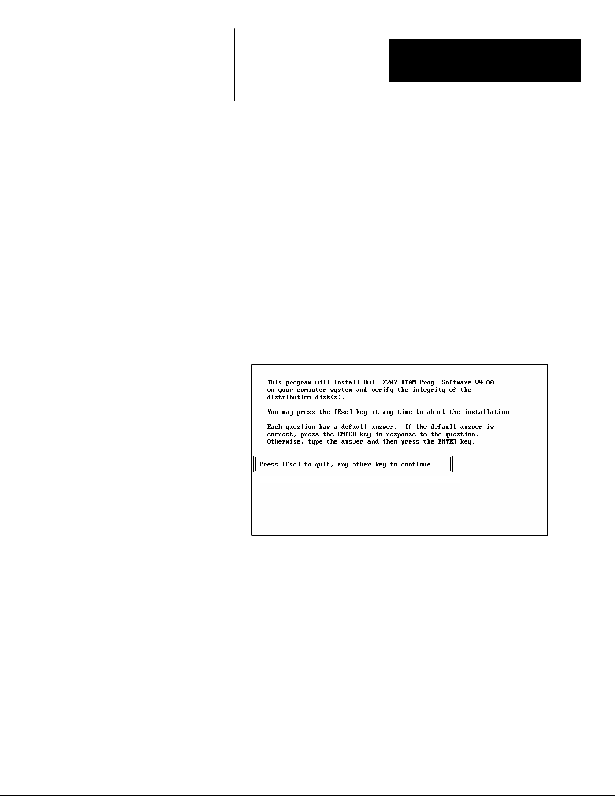
4. Type install and press [Return] to start the installation.
A:> install [Return]
The following screen appears:
2–3
Page 16
Chapter 2
Installing / Running
DTAM Programming Software
Installing DTAM
Programming Software
☞ You cannot install the DPS soft-
ware on the same drive on which
the Install program resides.
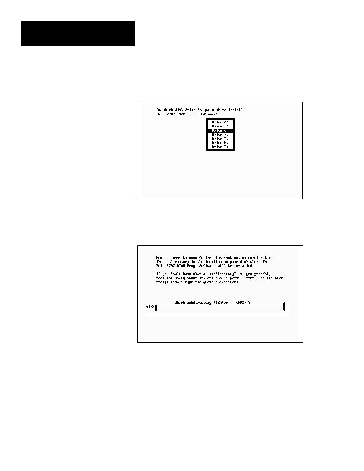
5. Press any key (other than [Esc]) to continue.
This screen appears.
6. Use the ["][#] arrow keys to highlight the drive on which you want to
install DPS and then press [Return]. The default drive is C:
This screen appears.
2–4
Page 17
Chapter 2
Installing / Running
DTAM Programming Software
☞ You can specify another
directory. The Install program
will create the directory if it
does not exist.
7. Press [Return] to install the DPS software in the \DPS subdirectory. The
Install program creates the subdirectory. If you enter your own
subdirectory name, the entire path name including colons, forward slash,
and name should not exceed 28 characters.
The status of the installation is displayed on the screen.
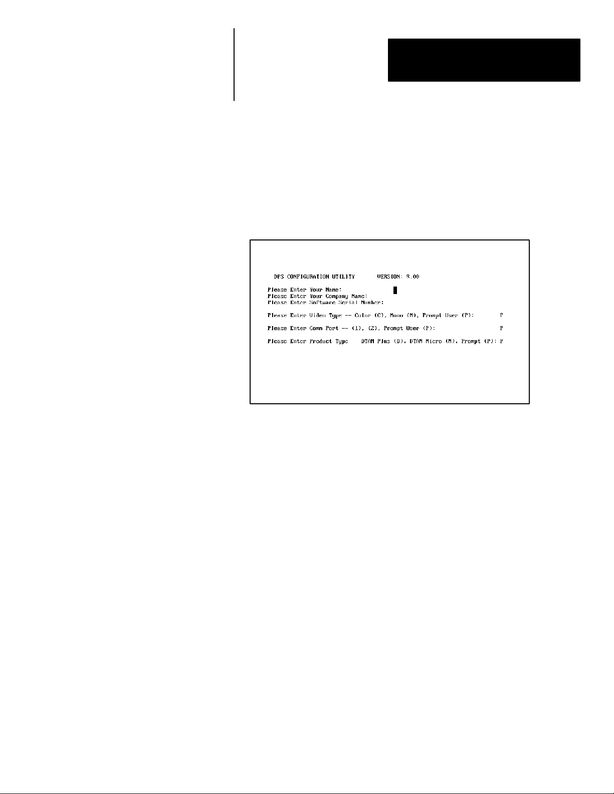
The DPS Configuration Utility screen then appears:
☞ Press [Return] at the Video
Type and Comm Port questions
to prompt the user for this
information during application
development.
8. Enter your name, company name, and software serial number (on
registration card). Also, enter the monitor type and communication port
used by your computer.
The software serial number is required when requesting phone support
(refer to startup screen on next page).
9. After responding to the above questions, you are asked to confirm the
configuration. Press [Return] to accept the configuration.
10. The installation is complete. You are returned to DOS at the new
subdirectory C: \DPS>.
2–5
Page 18
Chapter 2
Installing / Running
DTAM Programming Software
Running DPS
☞ If you installed the software in
another subdirectory, move to
that directory.
To run the DTAM Programming Software:
1. Verify that you are at the \DPS subdirectory where the software resides.
If you are not, enter cd \DPS and press [Return].
C:\DPS>
2. Type DPS and press [Return] to start the program.
C:\DPS> DPS [Return]
3. Specify whether you are using a color monitor. Enter [Y] or [N].
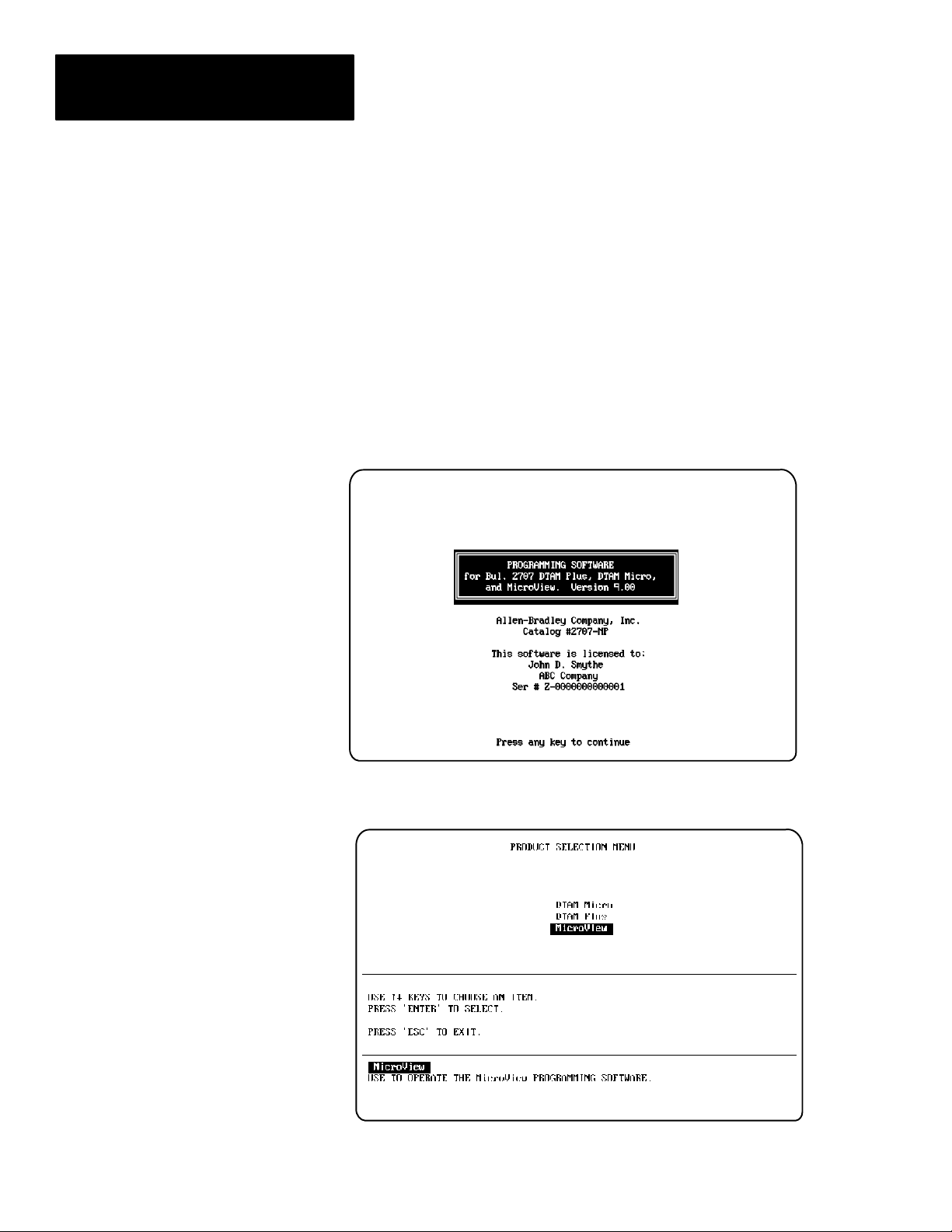
The startup screen displays. It identifies the DPS version and licensed
owner. A phone support number is provided for your assistance.
Technical Support
Voice: 440–646–6800
FAX: 440–646–6850 or 6890
E–mail: RACLEASKTHEEXPERT@RA.ROCKWELL.COM
Followed by this screen.
2–6
Page 19
Chapter 2
Installing / Running
DTAM Programming Software
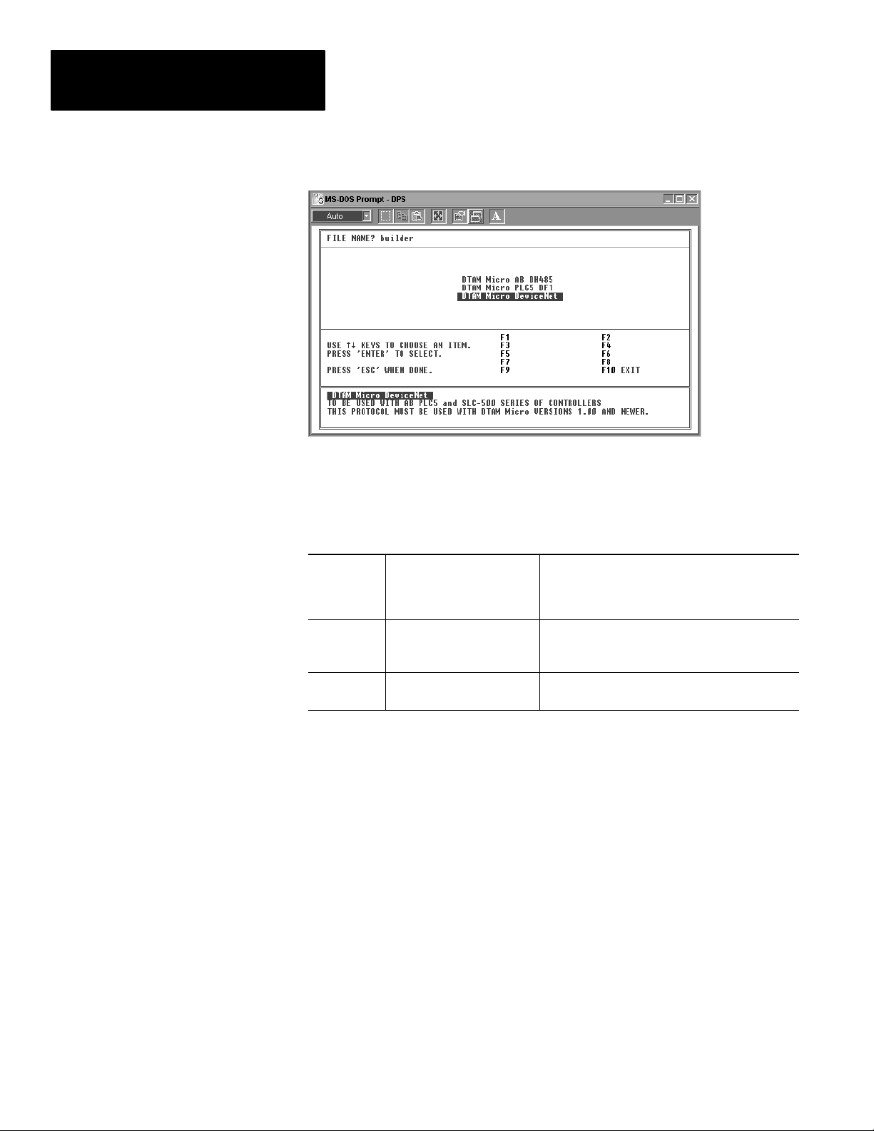
4. Select the product type you are creating an application for (DTAM Micro,
DTAM Plus, or MicroView) and press [Return].
The Opening Menu appears:
Plus, Micro, or MicroView
Depending upon selection.
2–7
Page 20
Chapter 2
Installing / Running
DTAM Programming Software
You are now ready to create a file for your application.
The following chart lists the various protocols and the corresponding
controllers:
DTAM Plus
DTAM Micro
MicroView
AB DH485
PLC5 DF1
PLC5 DF1
RI0
DN
AB DH485
PLC5 DF1
DN
Micro Logix DF1
DN
SLC or Micro Logix (Series C or later)
PLC5 or Micro Logix
PLC5 or Micro Logix
PLC5 or SLC w/1747-SN
PLC or SLC w/★-SDN
SLC or Micro Logix (Series C or later)
PLC5 or Micro Logix
PLC or SLC w/★-SDN
Micro Logix
PLC or SLC w/★-SDN
Note: Once a protocol has been selected and the file has been saved, you
can not change the protocol. A new file must be created when a different
protocol is selected.
2–8
Page 21
Chapter 2
Installing / Running
DTAM Programming Software
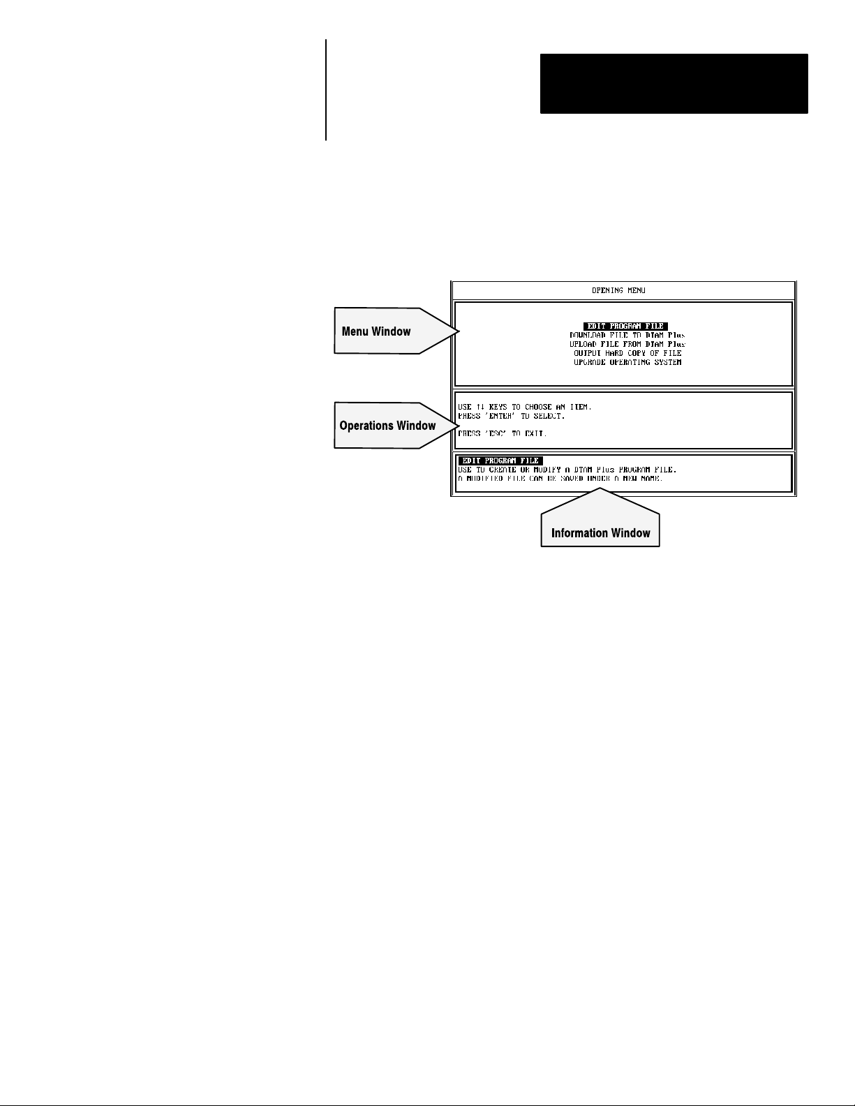
Menu Conventions
Figure 2.1 shows the format of DPS menu screens:
Figure 2.1
DPS Menu Screen Format
Menu Window
The Menu Window lists operations available at the current menu. To
select one of the operations, highlight the operation and press [Return].
Operations Windows
The Operations Window displays keyboard operations available at the
current Menu Window.
Information Window
The Information Window displays a brief explanation of each operation
available for the selected menu item.
2–9
Page 22
Chapter 2
Installing / Running
DTAM Programming Software
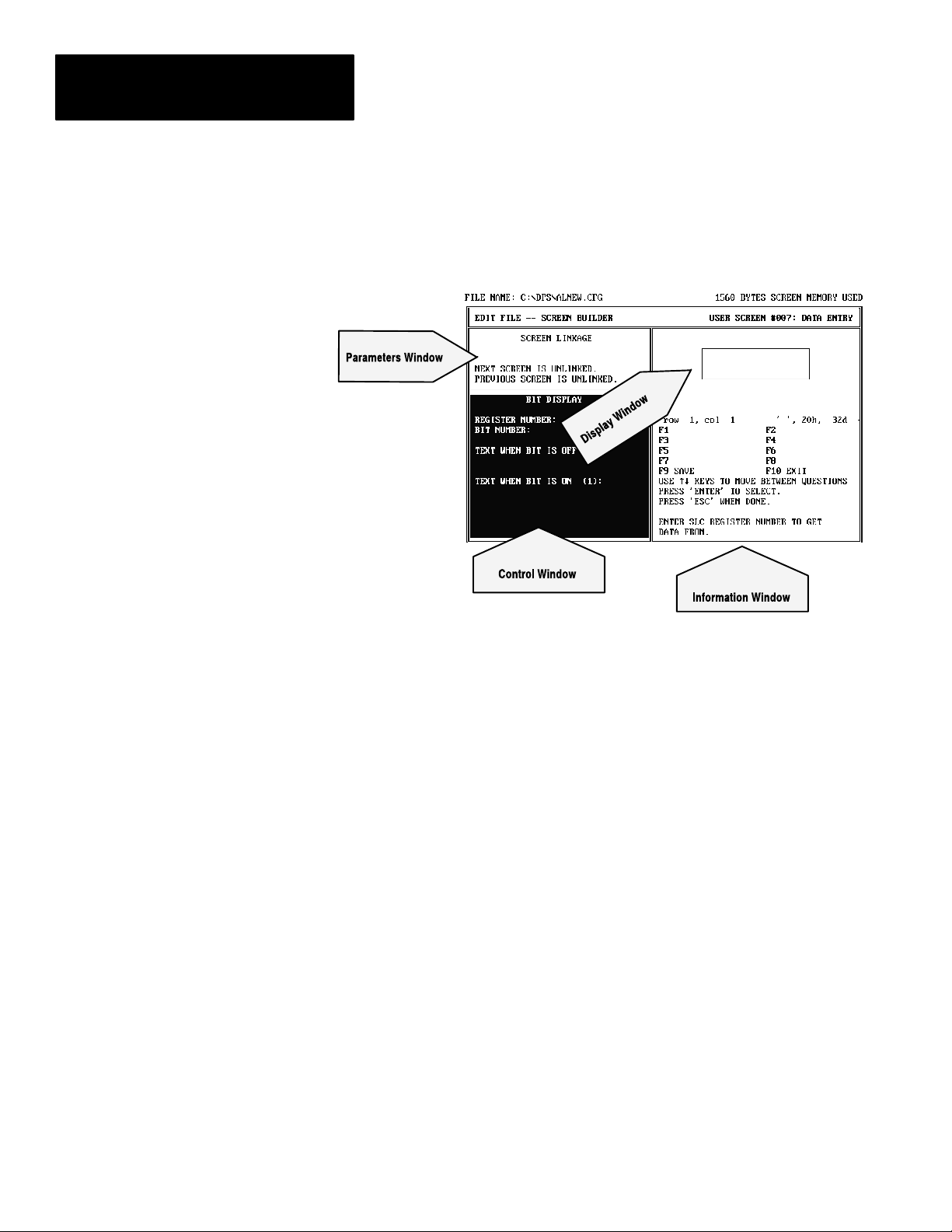
Screen Building Conventions
Figure 2.2 shows the Screen Builder format:
Figure 2.2
Screen Builder Format
There are two information lines at the top of the screen:
• The first line identifies the current program path and file name, as well as
screen memory usage to help you track the size of your program file.
• The second line identifies the current DPS operating area as well as the
current screen number and type.
Screen builder has four windows:
Parameters Window
The Parameters Window displays the linking definitions that have been
established for the current screen.
Display Window
The Display Window simulates the DTAM Plus (4 line display) or DTAM
Micro (2 line display) screen. It displays the formatted data and text as it
would appear to the DTAM operator.
Control Window
The Control Window displays the available data format selection and the
register information which can be defined for the current screen.
Information Window
The Information Window displays information about the function key
operations available at the current screen.
2–10
Page 23
Chapter 2
Installing / Running
DTAM Programming Software
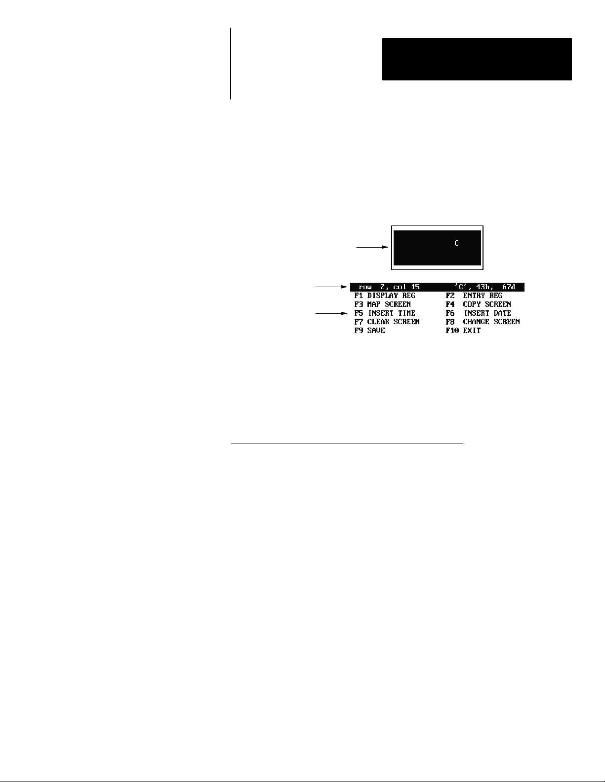
Cursor Status Line
Moving Around Screens
The cursor status line is located between the Display and Information
windows. This line displays the current row and column of the cursor.
Also listed is the character at that position along with the character ASCII
code in hex and decimal formats. Confirm character codes by placing the
cursor under the character and reading the code from the cursor status line.
The following example shows the character C at row 2, column 15.
Display Window
Cursor Status Line
Information Window
DPS uses menus to guide you through the application development process.
Select a menu item and the next menu or screen is displayed. The standard
keyboard operations are:
Linking Application Screens
Use these keys To
[°][±][²][³]
[Return] Select a menu item.
[Esc] Return to the previous menu.
Highlight a menu selection
DTAM application files allow you to present screens in a meaningful
sequence, a hierarchy of possible tasks and operations. To do this, you will
need to specify a link for each screen.
The linking function is the basis of a DTAM operator terminal’s power and
flexibility. When screens are linked, the DTAM becomes an interactive
operator workstation, one that can guide an operator through a hierarchy of
operations. This hierarchy can be as simple or as complicated as your
application requires.
Note: All application screens must be created before they can be linked.
2–11
Page 24

Page 25

Chapter
Objectives
A–B
3
Designing DTAM Plus and
DTAM Micro Applications
This chapter describes the differences between DTAM Micro and DTAM
Plus applications. Also provided are guidelines for creating applications.
Section Page
DTAM Plus / DTAM Micro Comparison 3–2
DTAM Plus / DTAM Micro File Types 3–3
Screen Types and Data Formats 3–4
Data Scaling 3–6
Application Example 3–8
Designing an Application 3–10
3–1
Page 26
Chapter 3
Designing DTAM Plus and
DTAM Micro Applications
DTAM Plus / DTAM Micro Comparison
Both the applications are created using DPS. The development of
applications for the DTAM Micro and DTAM Plus is very similar. This
manual shows screens for DTAM Plus applications, the DTAM Micro
screens are similar unless noted. The differences in application development
are related to differences in the operator terminals. The following table lists
these differences.
Function DTAM Plus DTAM Micro
Screen Capacity Up to 244 Screens Up to 244 Screens
Terminal Mode Yes No
Function Key Screen Selection No Yes
Alarm LED Yes No
Background Monitor Yes No
Application Upgrade / Downgrade Yes No
Contrast / Backlight Adjustment Yes No
Time / Date Functions Yes No
PID File Operations Yes No
SFC File Operations Yes No
Block Transfer File Operations Yes No
Floating Point File Operation Yes No
Bargraph Display Yes No
[Y], [N], [PREV MENU] keys Yes No
Printer Port Yes No
3–2
The main difference in designing DTAM Micro and DTAM Plus applications
is the screen size.
DTAM Plus
4 Lines x 20 Characters
DTAM Micro
2 Lines x 20 Characters
Page 27
Chapter 3
Designing DTAM Plus and
DTAM Micro Applications
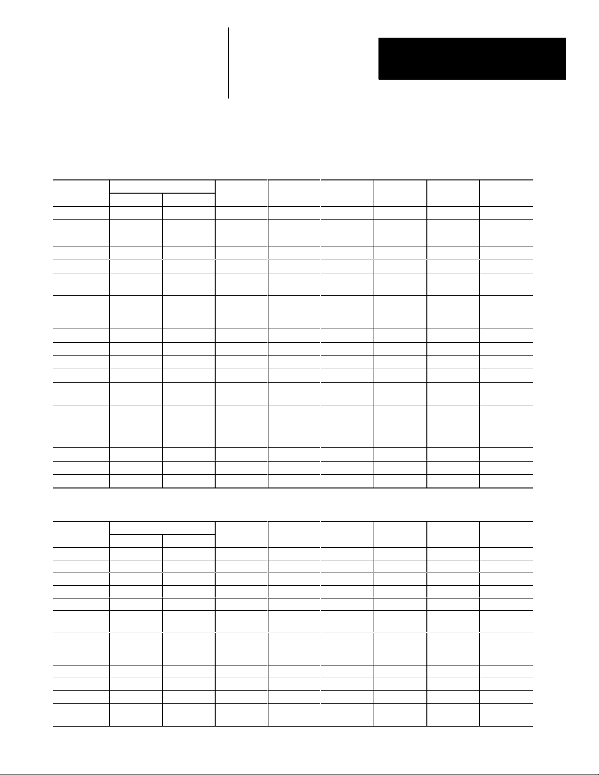
DTAM Plus / DTAM Micro File Types
File Type
Output Yes Yes Read O 0
Input Yes Yes
Status Yes Yes Read / Write S 2 0-127 NA 0-15
Bit (Binary) Yes Yes Read / Write B 3-999 0-999 NA 0-15999
Timer Yes Yes Read / Write T 3-999 0-999 PRE, ACC EN, TT, DN
Counter Yes Yes Read / Write C 3-999 0-99 PRE, ACC
Control Yes Yes Read / Write R 3-999 0-999 LEN, POS
Integer Yes Yes Read / Write N 3-999 0-999 NA 0-15
Floating Point Yes Yes (Limited) Read / Write F 3-999 0-999 NA NA
ASCII Yes Yes Read A 3-999 0-999 NA 0-15
BCD Yes Yes Read / Write D 3-999 0-999 NA 0-15
Block
Transfer
Message Yes Yes Read MG 3-999 0-584
PID Yes No Read / Write PD 3-999 NA NA NA
SFC Yes No Read / Write SC 3-999 NA NA NA
ASCII String Yes Yes Read ST 3-999 0-799 LEN, CHAR 0-15
➀ Octal format, all other values are decimal. ➁ Remote I/O allows the DTAM to write it’s own output words.
File Type Supported By;
DTAM Plus
Yes No Read / Write BT 3-999 0-999 NA NA
DTAM Micro
Both the DTAM Micro and DTAM Plus can read and write PLC and SLC
controller files. Refer to the following when designing applications.
PLC-5 File Types
Integer
Read / Write Identifier File Number Element
0-277➀
Read➁
I 1
0-277➀
Integer
Sub-Element
NA
NA
ERR, RLEN,
DLEN,
DATA 90-51)
Bit Number
0-17➀
0-17➀
CU, CD, DN.
OV, UN
EN, EU,
DN, EM, ER,
UL, IN, FD
NR, TO,
EN, ST, DN,
ER, CO, EW,
SD, SE
SLC File Types
File Type
Output Yes Yes Read O 0 0-255 NA 0-15
Input Yes Yes Read I 1 0-255 NA 0-15
Status Yes Yes Read / Write S 2 0-82 NA 0-15
Bit (Binary) Yes Yes Read / Write B 3, 9-255 0-255 NA 0-4094
Timer Yes Yes Read / Write T 4, 9-255 0-255 PRE, ACC EN, TT, DN
Counter Yes Yes Read / Write C 5, 9-255 0-255 PRE, ACC
Control Yes Yes Read / Write R 6, 9-255 0-255 LEN, POS
Integer Yes Yes Read / Write N 7, 9-255 0-255 NA 0-15
ASCII Yes Yes Read A 3-999 0-999 NA 0-15
ASCII String Yes Yes Read ST 3-999 0-799 LEN, CHAR 0-15
Floating Point Yes
③ Need SLC 5/03 Series C w/OS 301 or SLC 5/04.
File Type Supported By;
DTAM Plus
DTAM Micro
Yes③
(Limited)
Read / Write Identifier File Number Element
Read / Write F 3-999 0-999 NA NA
Integer
Integer
Sub-Element
Bit Number
CU, CD, DN,
OV, UN
EN, EU,
DN, EM, ER,
UL, IN, FD
3–3
Page 28
Chapter 3
Designing DTAM Plus and
DTAM Micro Applications
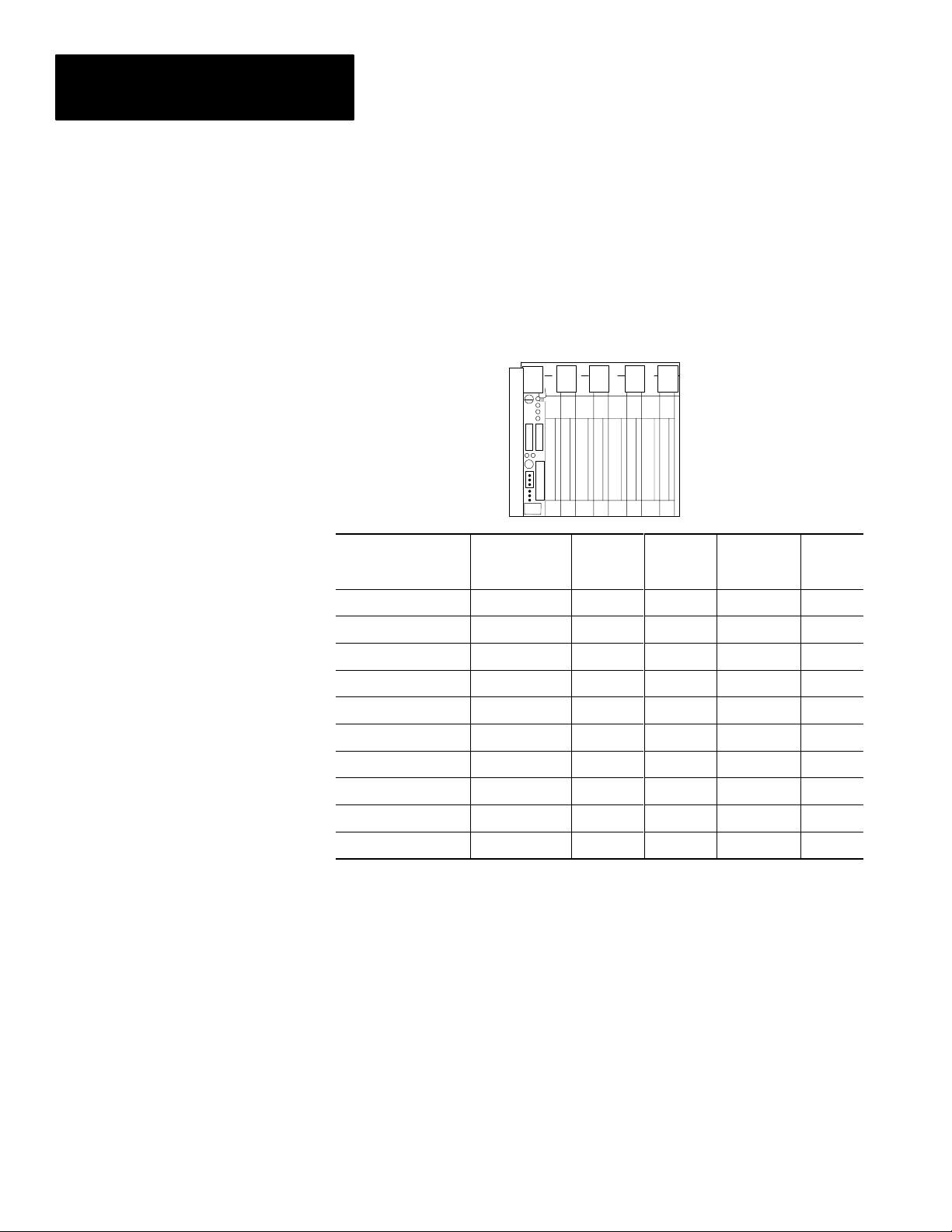
Screen Types and Data Formats
Some application screens require that you specify register information.
Each DTAM screen type supports different data formats. The following table
lists each screen type and the data formats supported.
PLC Data Formats
Display, Alarm,
Format
Bit
16 Bit Signed Integer
16 Bit Unsigned Integer
16 Bit BCD
16 Bit Hex
32 Bit Floating Point
32 Bit Unsigned Integer
32 Bit BCD
32 Bit Hex
ASCII
➀ Bar Graph, Printer Form, and Background Monitor are only available on DTAM Plus Operator
Modules.
Printer Form ➀
Screens
n
n
n
n
n
n n n
n n n
n n n
n
n
Data Entry
Screens
n n
n n n n
n n
n n n n
Bar Graph
Screens ➀
Background
Monitor ➀
Recipe
Screens
3–4
Page 29
Chapter 3
Designing DTAM Plus and
DTAM Micro Applications
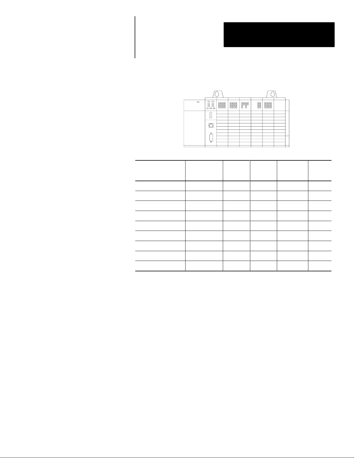
SLC Data Formats
Display, Alarm,
Format
Bit
16 Bit Signed Integer
16 Bit Unsigned Integer
16 Bit BCD
16 Bit Hex
32 Bit Unsigned Integer
32 Bit BCD
32 Bit Hex
ASCII
➀ Bar Graph, Printer Form, and Background Monitor are only available on DTAM Plus Operator
Modules.
Printer Form ➀
Screens
n n n
n n n n n
n n n
n n n n n
n
n n n
n n n
n
n
Data Entry
Screens
Bar Graph
Screens ➀
Background
Monitor ➀
Recipe
Screens
3–5
Page 30
Chapter 3
Designing DTAM Plus and
DTAM Micro Applications
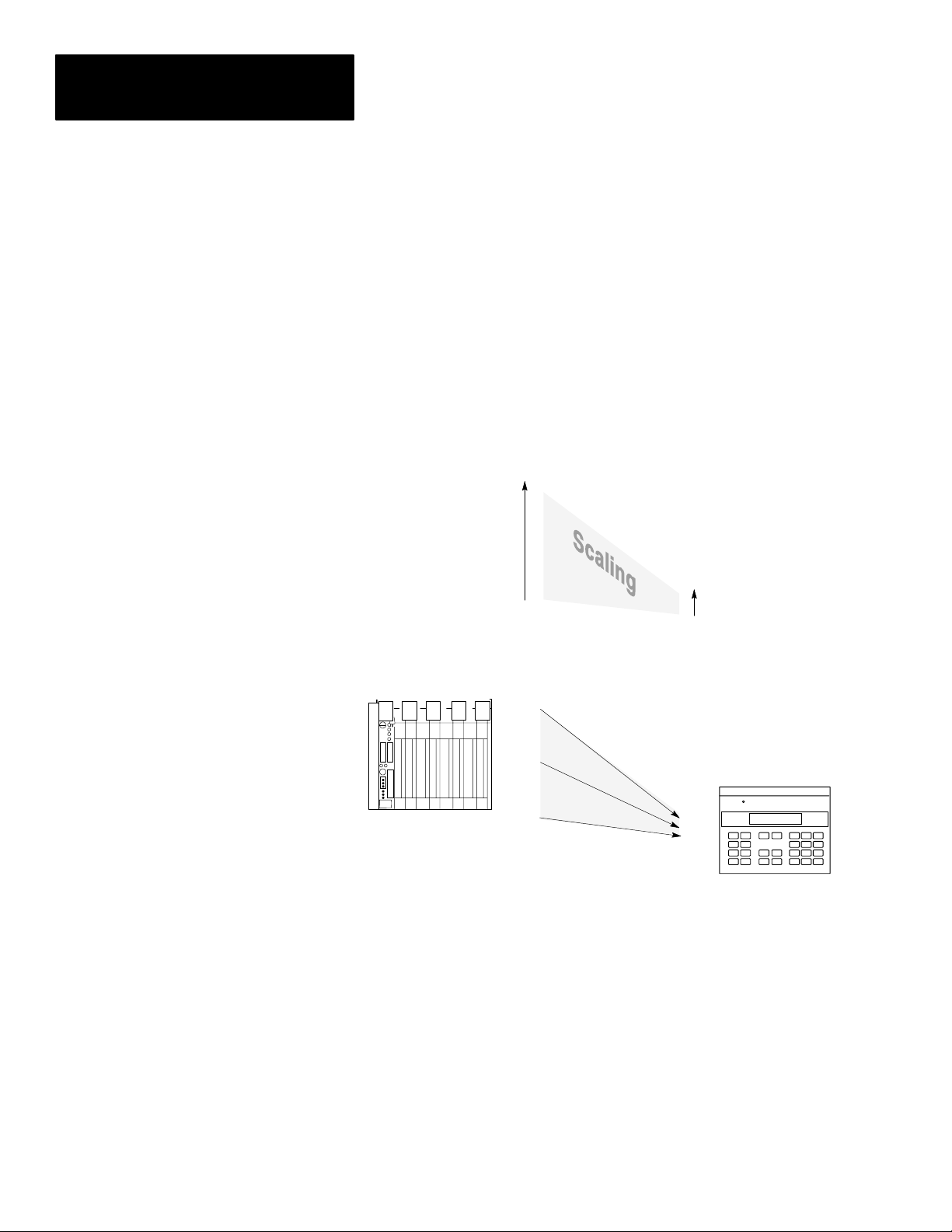
Data Scaling
Data entered by an operator can be scaled from engineering units such as
gallons or PSI to machine control values. Likewise, data displays can
take raw numeric values and scale them so they are displayed in
engineering units.
Scaling of data is accomplished by defining a proportional ratio between the
register value range and the display or entry value range. If a 1:1 ratio exists,
the DTAM displayed or entered value equals the controller register value.
Here is an example of scaling using a data display to scale a register data
range of 0 to 4,095 to a DTAM display range of -100 to +300.
Controller
Register Limits
4,095
4,095
DTAM
Display Limits
+300
0
-100
If the Display
Register Contains:
4,095
2,047
This Value
Is Displayed:
0
+300
+100
-100
When the ratio between the controller register values and DTAM display or
entry values is not a multiple of 2, the value is rounded. Rounding may
result in a 1 count error. Depending upon the direction of the scaling, this
means that:
• The DTAM display value may be off by 1 when the controller register
value is scaled
• The controller register value may be off by one when a DTAM data entry
is scaled.
An error screen appears if a rounding error occurs at the end points of a data
range. You must either increase the minimum or decrease the maximum
range of either the controller register or display ranges.
3–6
Page 31

Chapter 3
Designing DTAM Plus and
DTAM Micro Applications
Scaling Formulas
The scaling formula for a DTAM display value is:
Displayed Value= m x Register Value + b
Where:
Display Maximum Value – Display Minimum Value
m =
Register Maximum Value – Register Minimum Value
Display Minimum Value – ( m x Register Minimum Value )
b =
The scaling formula for an entered valued is:
Register Value = m x Entered Value + b
Where:
Register Maximum Value – Register Minimum Value
m =
b =
Entry Maximum Value – Entry Minimum Value
Register Minimum Value – ( m x Entry Minimum Value )
Scaling example: Register Range = 0 ! 4,095
Display Range = -100 ! +300
Actual Register Value = 2,047
300 - (-100)
m =
4,095 - 0
b =
-100 - (0.0977 x 0) = -100
= 0.0977
Displayed Value = 0.0977 x 2,047 + (-100)
= 99.9919
= 100
3–7
Page 32

Chapter 3
Designing DTAM Plus and
DTAM Micro Applications
Application Example
Sub Menu
1. East Pump/Tank
2. West Pump/Tank
The following example shows typical menus and screens of a DTAM Plus
application. The same application could be created on a DTAM Micro with
the following exceptions:
• DTAM Micro screen is 2 lines by 20 characters. Large screens would
have to be shortened or broken down into separate screens.
• The DTAM Micro cannot support a bar graph screen.
DTAM Plus Application Outline
Main Menu
1. Pump/Tank Levels
2. Pump Control
3. Flow/Level Status
4. Controller Status
Security
* Restricted Access *
Enter Your Security
Code: * * * * * * * *
Data Display
East Pump: 280 CFM
West Pump: 0 CFM
North Pump: 207 CFM
South Pump: 70 CFM
Data Display
Controller Status
Scan Time is: 7 ms
Controller is: Online
Battery Power: OK
Data Display
East Feed Pump
Main Pump is: On
Fill Rate: 280 CFM
Tank is 38% Full
Data Display
East Feed Pump
Efficiency: 77%
Run Time:693 Hrs.
Next Serv:307 Hrs.
3–8
Data Display
West Feed Pump
Main Pump is: Off
Fill Rate: 8 CFM
Tank is 72% Full
Data Display
West Feed Pump
Efficiency: 83%
Run Time:22 Hrs.
Next Serv:978 Hrs.
Data Entry
East Tank: 38% Full
Setpoint is 280 CFM
Please Enter New
Setpoint: 145
Data Entry
West Tank: 72% Full
Setpoint is 170 CFM
Please Enter New
Setpoint:
Data Display
East Tank: 38% Full
West Tank: 72% Full
North Tank: 16% Full
South Tank: 5% full
Bar Graph
Tank Total Pumping
Rate is: 557 CFM
Page 33

Chapter 3
Designing DTAM Plus and
DTAM Micro Applications
Example Application Description
Pump/Tank Levels
When Pump/Tank Levels is selected from the Main Menu, a Sub-Menu
displays two new choices (East Pump/Tank and West Pump/Tank). Selecting
either of these Sub-Menu items allows you to display pump and tank
information for the East or West systems.
Pump Control
Allows you to enter new pump setpoints to be entered. A security code is
required to access the Data Entry screens.
Data Entry screens use data from the SLC or PLC (% Full & CFM) to
display this information along with a prompt to enter a new setpoint. When a
new setpoint is entered, the value is checked to verify that it is within the
programmed limits. If the value is within the entry limits, the number is then
scaled to engineering units and sent to the SLC or PLC. If the value is
outside the limits, an error message informs you of the valid range. You can
then enter another value.
Flow/Level Status
Allows access to three Data Display screens identifying the flow rates for the
four pumps. All values are updated in real time and are scaled to engineering
units by the DTAM. Using the [NEXT] key on the DTAM keypad, an
operator can display the sequence of Data Display screens. The Bar Graph
screen (DTAM Plus only), lets you view the data in a graphic format.
Controller Status
Shows the status of the controller (SLC or PLC).
3–9
Page 34

Chapter 3
Designing DTAM Plus and
DTAM Micro Applications
Designing an Application
Appendix B contains worksheets for designing both DTAM Micro and
DTAM Plus applications. Both application layout and screen design
worksheets are provided.
Use the application design worksheets to layout a logical sequence of
screens. Make copies of the worksheets as needed. On each worksheet, list
the screen numbers, type of screens, register numbers, etc.
DTAM Application Worksheet
Use the screen worksheets to define screen text and layout. Make copies of
the screen worksheets and write out each application screen.
DTAM Plus
Screen Worksheet
Screen #
DTAM Micro
Screen Worksheet
Screen #
Before you design an application, become familiar with the types of screens
and how they function. To assist you, a sample application is provided in
this chapter. In addition, you should become familiar with the controller files
and data types supported for each operator module type and selected protocol
(see previous section). When register information is required, this manual
lists the applicable data formats (such as ASCII or 16 Bit Hex) for each
controller file type.
3–10
Page 35

Chapter 3
Designing DTAM Plus and
DTAM Micro Applications
Recommended sequence for creating an application:
Step 1 On paper, design all the operator screens with the associated register
numbers, and produce a map of how all screens are linked together.
Step 2 Construct all screens using DPS. Save the program file without
linking.
Step 3 Link the application screens. Use the design from step 1.
When you have established all links, save the program file.
An error display will warn you of any unlinked screens.
Step 4 Download the application file.
Step 5 Use the Simulate function (described in the DTAM Micro or DTAM
Plus user manuals) to verify operations such as screen links, text, and
screen types.
Step 6 Run the application.
3–11
Page 36

Page 37

Chapter
Chapter Objectives
Opening Menu
A–B
4
Creating or Editing
an Application File
This chapter describes how to open, edit and save an application file.
Section Page
Opening Menu 4–1
Edit Application File 4–2
Save Application File 4–4
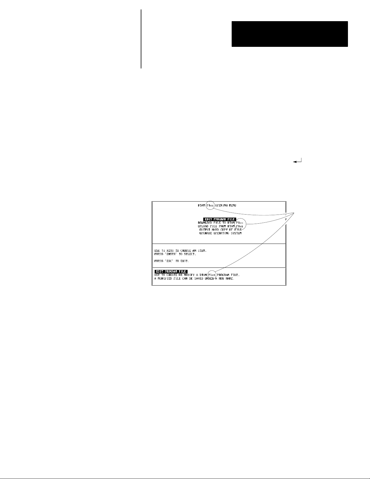
The Opening Menu is the first menu displayed each time you run
the software.
Note: If you specified prompts for monitor type and product type during
installation, these prompts will appear before the opening menu.
The Opening Menu displays the following operations:
• Edit Program File
• Download File to DTAM Plus or Micro
• Upload File from DTAM Plus or Micro
• Output Hard Copy of File
• Upgrade Operating System
4–1
Page 38

Chapter 4
Creating or Editing an Application File
Edit Application File
The directory only lists files compatible
with the currently specified hardware type.
For example, if DTAM Micro is specified
only DTAM Micro applications are listed.
To create or edit an application:
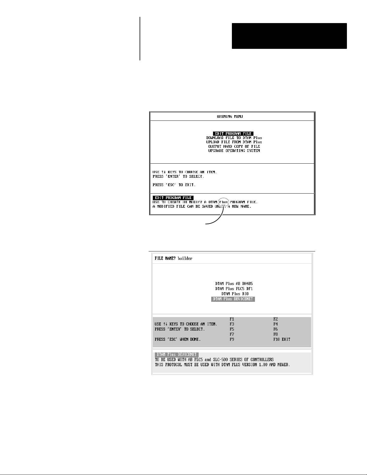
1. Select Edit Program File to create or edit a DTAM application file.
You are prompted for the file name to edit or create. All DTAM
application files in the current directory are listed.
If files already exist, each file name is followed by the type of Operating
System the file was created for:
• AB DH485 for point to point or 32 node operation with SLC
controllers.
• PLC5 DF1 for DF1 connection to PLC-5 serial port (channel 0).
• AB BASIC only applies to DTAM Plus programming when
communicating with an SLC BASIC module (Catalog No.
1746-BAS).
• RIO only applies to DTAM Plus programming when communicating
with an a PLC-5 or SLC 5/03 / 5/04 over a remote I/O link.
4–2
2. Select the name of an existing application file or enter a new file name.
If you entered a new file name, you must select an operating system:
Page 39

Chapter 4
Creating or Editing an Application File
After you select an existing file or enter the operating system (for new
files), the Edit File - Option Selection menu is displayed.
DTAM Micro or
MicroView or
DTAM Plus
3. Access the following functions from the Edit File - Option Selection
menu to create your application screens and enter configuration data.
4–3
Page 40

Chapter 4
Creating or Editing an Application File
Save Application File
Select this
Menu Option:
DTAM Configuration Data
Screen Builder
Alarm Screen Builder
Background Monitor
Print Form Builder
Function Key Builder
Applies to:
DTAM-
Plus
Micro-
View
✓
✓ ✓ ✓
✓ ✓
✓
✓
✓
DTAM-
Micro
✓
✓
Set configuration and operating
parameters.
Create or modify application
screens.
Create or modify alarm screens.
Assign background registers and
limits for the DTAM Plus to monitor.
Create or modify DTAM Plus
Printer Forms.
Assign application specific
operations to the DTAM Micro
function keys.
To
Save the application periodically while you are working on the application
screens and save the file again before you exit the software.
To save an application periodically during editing:
1. Press [F9].
You are prompted to save the application under the current file name or
you can enter a new file name.
Note: If the same file name currently exists under a different product
type, you are prompted if you want to overwrite the existing file.
4–4
Page 41

Chapter 4
Creating or Editing an Application File
2. Press [Return] to save the application under the file name entered when
the application file was opened.
Or enter a new file name:
If you were creating a new file, the new file name replaces the file
name entered when the application was opened.
If you are editing an existing file, the original file is unchanged.
The file and all edits made prior to the last save are stored under the
new file name.
3. After saving the file, you can continue with your editing of the application
To save an application before exiting:
1. Exit the software by pressing [F10].
You are prompted save the application under the current file name or you
can enter a new file name.
2. If you enter a new file name, the original file is unchanged. All edits are
stored under the new file name.
After saving the file, you are returned to a DOS prompt.
4–5
Page 42

Page 43

Chapter
Chapter Objectives
A–B
5
Using Screen Builder
This chapter describes options common to all of the Screen Builder types.
Section Page
Screen Builder 5–1
Accessing Screen Types 5–2
Editing Screen Displays 5–4
Copying Screens 5–5
Selecting Other Screens 5–6
Clearing Screens 5–7
Inserting Time or Date 5–8
Exiting Screen Builder 5–9
Screen Builder
Screen Builder is one of the menu items available when you select Edit
Program File from the Opening menu. Use Screen Builder to create:
• Menus and Sub-menus
• Data Entry screens
• Data Display screens
• Security screens
• Recipe screens
• Bar Graph screens (DTAM Plus only)
Alarm and Special menu security screens are not created within Screen
Builder. These screens are created using other DPS functions:
• For alarm screens, refer to Chapter 13.
• For the Special menu security screen, see Chapter 14.
5–1
Page 44

Chapter 5
Using Screen Builder
Accessing Screen Types
To access Screen Builder screens:
1. Select Screen Builder from the Edit File - Option Selection menu.
The Screen Builder for the main menu screen (screen #1) displays:
5–2
2. If you have designed your main menu screen, you can create it now as
described in Chapter 6. Each application must have a main menu screen.
If you want to create another screen type, proceed to the next step.
Page 45

Chapter 5
Using Screen Builder
3. Press [F8] on any screen to access the other screen types. You are
prompted for a screen number:
Press [F6] to go to the next available unused screen or [F8] to view the
contents of the next programmed screen.
4. If you enter any screen number other than screen #1 (main menu screen),
you are prompted for a screen type:
5. Select a screen type. A Screen Builder for the selected screen type is
then displayed. Refer to Chapters 6 through 11.
Screen Type Chapter
Menus and Sub-Menus 6
Data Displays 7
Data Entry 8
Security 9
Recipe 10
Bar Graph ➀
➀ DTAM Plus only.
11
5–3
Page 46

Chapter 5
Using Screen Builder
Editing Screen Displays
5–4
When you are editing screen text, the following editing operations are
available:
Screen Text Edit Functions
Screen Edit Key Function
Arrow keys
[°] [±] [²] [³]
[Del] Deletes the character at the cursor position.
[Back Space] Deletes the character to the left of the cursor position. The
[Ins] Toggles the insert mode on or off. Characters entered in the
Move the screen cursor.
cursor is moved to the left one space.
insert mode are shifted to the right. A block shaped cursor
indicates the insert mode is on. An underline cursor indicates
that insert mode is off.
The extended DTAM character set can be used, refer to Appendix A for
additional information.
Screen Builder Function keys
The following function keys are available on most screen types.
Function
Key
[F3] LINK
[F4] COPY
[F5] INSERT TIME
[F6] INSERT DATE
[F7] CLEAR
[F8] CHANGE
[F9] SAVE
[F10] EXIT
Designation
SCREENS
SCREEN
SCREEN
SCREEN
Applies to:
DTAM Plus DTAM Micro
✓ ✓
✓ ✓
✓
✓
✓ ✓
✓ ✓
✓ ✓
✓ ✓
Function
Accesses screen mapping functions
that link application screens in a
logical sequence.
Link screens only after all of the
screens have been created.
Copies an existing screen to or from
the current display window. Both the
source and destination screens must
be of the same type (such as Data
Display screens).
Inserts the time into the display.
Only available with a DTAM Plus
having the Calendar/Clock option.
Inserts the date into the display.
Only available with a DTAM Plus
having the Calendar/Clock option.
Clears the current screen. You have
the option of clearing only the screen
text or deleting the entire screen
including any linking you may have
established.
Displays menu for selecting another
screen type.
Saves the application without exiting
the Screen Builder function.
Prompts you to save the application
to the current file and exits the DPS
software
Page 47

Chapter 5
Using Screen Builder
Copying Screens
Use the copy function [F4] to save time when creating similar screens. Both
the source screen and the destination screen must be of the same type. For
example, you can’t copy Data Entry screen text into a Data Display screen.
When you copy a screen, all register data and display text is also copied.
Edit the screen as needed after copying.
To copy a screen:
1. Open the screen you want to copy the screen to or from. In this example
a Data Display screen:
2. Press [F4].
You are prompted for the screen to copy to or from:
3. Press [F1] to copy the current screen to another screen. Press [F2] to
copy another screen to the current screen.
You are prompted for a screen number.
4. Enter the screen number and press [Return].
The screen is copied.
5. Edit the copied screen text and/or register data, refer to descriptions of
individual screen types (Chapters 6 through 11).
5–5
Page 48

Chapter 5
Using Screen Builder
Selecting Other Screens
After you have completed an application screen, use [F8] Change Screen to
edit another screen. You can change to any screen except an alarm screen.
Use the Alarm Builder function (Chapter 13) to access alarm screens.
To change screens:
1. Select [F8] Change Screen.
You are prompted for a screen number.
8
2. Enter the screen number you want to change to or select one of the
function keys:
Function Key Designation Function
[F1] FIRST
SCREEN
[F6] NEXT
UNUSED
[F7] LAST
SCREEN
[F8] NEXT PROG Selects the next programmed screen.
Returns to screen #1, the main menu.
Selects the next unused screen.
Selects the last programmed screen.
The selected screen is displayed.
5–6
Page 49

Chapter 5
Using Screen Builder
Clearing Screens
Use the [F7] Clear Screen function to clear all or part of the currently
displayed screen.
To clear a screen:
1. Open the screen you want to clear.
2. Select [F7] Clear Screen.
You are prompted for a clear screen option:
8
3. Select the Clear Screen option.
Press: To:
ENTER
[Return]
DELETE
[Del]
ESCAPE
[Esc]
Clear the display text only. Screen linking and register data for the screen
are not deleted.
Clears the entire screen including screen display text, register data, and
screen links.
Cancels the clear screen function.
The screen is cleared.
4. Continue programming or change to another screen.
5–7
Page 50

Chapter 5
Using Screen Builder
Inserting the Time or Date
If you are programming a DTAM Plus with a clock/calendar option, you can
insert the time or date into any application screen. Time and date functions
are not available on the DTAM Micro.
The time field takes up 5 character positions and is displayed in the
format HH:MM. AM/PM and seconds are not displayed to conserve space.
However AM/PM and the seconds are shown on print forms in the format
HH:MM:SS AM.
The date field takes up 9 character positions and is displayed in the format
MMM/DD/YY.
To insert the time or date:
1. Use the arrow keys to position the cursor where you want to insert the
date or time.
2. Press [F5] to insert the time or [F6] to insert the date.
The current date or time is inserted on the display:
Time
Date
3. Continue programming the remainder of the screen.
5–8
Page 51

Chapter 5
Using Screen Builder
Exiting Screen Builder
You can exit Screen Builder at any time during the design of an application.
Screen edits are not lost when you exit Screen Builder, however, we
recommend that you press [F9] SAVE before exiting.
To exit Screen Builder:
1. Press [Esc].
If you haven’t established screen linking, you are provided a reminder:
2. Press [Y] to acknowledge the reminder (if displayed).
After exiting Screen Builder, the Edit File - Option Selection menu
is displayed.
You can re-enter Screen Builder later for additional edits or to establish
screen linking.
5–9
Page 52

Page 53

Chapter
Chapter Objectives
Menu Screens
A–B
6
Creating Menu and
Sub-Menu Screens
This chapter describes how to create the main menu and sub-menu screens.
Section Page
Menu Screens 6–1
Building a Menu 6–2
Main Menu and Sub-Menu Screen Builder 6–3
Creating a Menu Screen 6–4
Menu Screens provide easy access to different parts of an application.
Menus structure an application on the basis of specific tasks and
responsibilities.
Each menu screen may consist of up to 8 different menu items. When
selected (by pressing a corresponding numeric key), a menu item displays
the linked screen or sub-menu.
A typical menu screen might look like this:
1. Temp Set 3. Level
2. Monitor
Main Menu Screens
The Main Menu is always operator screen #1. This menu lists the primary
components of your application. All other menus and data screens are
accessed from this screen.
There are two differences between the main menu and sub-menus:
• The DTAM Plus [MAIN MENU] or DTAM Micro [MENU] key displays
the Main Menu. This key is active at all times, unless an alarm is
detected.
• The Main Menu is the first screen that appears after a restart or reset,
unless an alarm is detected.
Sub-Menu Screens
Sub-menu screens are identical in appearance to the main menu screen.
Sub-menu screens enable you to expand the scope of an application by
providing directed choices through linked menus. This allows you to
construct a large application and maintain efficient access to specific areas.
6–1
Page 54

Chapter 6
Creating Menu and
Sub-Menu Screens
Building a Menu
When you build a menu, you are directing the operator to more specific
screens. A menu is a numbered list of components available at the current
stage of a process. Number each successive menu entry sequentially. The
number tells the operator which DTAM keypad key ([1] through [8]) to press
for each menu item (1 through 8).
The following example shows the menu structure of a DTAM Plus
application. The operator uses the DTAM numeric keypad keys to select a
menu item. Pressing [1] on the keypad selects the Pump Application screen.
Screen #11 is linked to keypad key [1] on the DTAM while this menu is
displayed. Pressing keypad key [2] on the DTAM Plus displays another
menu which has different links assigned to keypad keys [1],[2] and [3].
Screen 11 Screen 20 Screen 39 Screen 40
Main Menu
Items 1 through 8 correspond
to DTAM keypad keys
1 through 8. Each key can
be linked to a screen number.
To assign menu text, position the cursor at the location you want the list to
begin and enter text.
Enter Menu
Text here.
Screens can’t be linked to DTAM keypad keys ([1] - [8]) until you have first
created the screens. After creating your application screens, you can return
to the menu screens and assign the links, refer to Chapter 12.
6–2
Page 55

Chapter 6
Creating Menu and
Sub-Menu Screens
Main Menu and Sub-Menu Screen Builder
The screen for creating the main menu and sub-menu screens is the same for
the DTAM Plus and DTAM Micro. The only difference is the DTAM Micro
has a 2 line display and the DTAM Plus can display 4 lines.
Menu Screen Builder Function keys
Applies to:
Function
Key
[F2] CHANGE
[F3] LINK
[F4] COPY
[F5] INSERT TIME
[F6] INSERT DATE
[F7] CLEAR
[F8] CHANGE
[F9] SAVE
[F10] EXIT
Designation
PREV
SCREENS
SCREEN
SCREEN
SCREEN
DTAM
Plus
DTAM
Micro
✓
✓ ✓
✓ ✓
✓
✓
✓ ✓
✓ ✓
✓ ✓
✓ ✓
Function
Only applies to DTAM Plus sub-menu screens.
Displays linking prompt used to designate the
screen displayed when the operator presses the
[PREV MENU] key (DTAM Plus only).
Accesses screen mapping functions that link
application screens in a logical sequence.
Link screens only after all of the screens have
been created. Refer to Chapter 12.
Copies an existing screen to or from the current
display window. Both the source and destination
screens must be of the same type (Menu
screens).
Inserts the time into the menu. Only available
with a DTAM Plus having the Calendar/Clock
option.
Inserts the date into the menu. Only available
with a DTAM Plus having the Calendar/Clock
option.
Clears the current screen. You have the option
of clearing only the screen text or deleting the
entire screen including any linking you may have
established.
Selects another operator screen.
Saves the application without exiting the Screen
Builder function.
Prompts you to save the application to the
current file and exits the DPS software.
6–3
Page 56

Chapter 6
Creating Menu and
Sub-Menu Screens
Creating a Menu Screen
To create a menu screen:
1. Select Screen Builder from the Edit File - Option Selection menu.
The screen builder for the main menu (screen #1) is displayed.
2. If you are creating a sub-menu, press [F8], enter the screen number, and
select a sub-menu screen type.
The screen builder for a sub-menu is displayed. The sub-menu screen
builder is the same as the main screen (shown above).
3. Enter the screen text. The sequence, length and location of the text does
not matter but make sure you number each menu item (1 through 8).
Enter menu
text.
4. Press [F9] to save the screen.
Note: You can’t link screens to a menu until all of the application screens
have been created. Chapter 12 describes how to link screens to a menu.
6–4
Page 57

Chapter
Chapter Objectives
Data Displays
A–B
7
Creating Data Display Screens
This chapter describes how to create data display screens.
Section Page
Data Displays 7–1
Scaling 7–1
Data Display Screen Builder 7–2
Inserting Display Data 7–3
Display Register Format Selections 7–5
Data display screens allow you to monitor the value of registers in the SLC
or PLC. The DTAM continuously reads the registers to update (at a userdefined rate) the displayed values.
Scaling
This is how a data display screen may appear:
Tank Level = 33 Gallons
10% Full Press NEXT
To construct data display screens, you need to specify:
• The type of screen as data display
• The type of data stored in the PLC or SLC register
• The register to access (address)
• Any data format and display information
• The display position for the data
• Any additional text information that you want to display
Data in controller data files can be scaled to standard engineering units such
as gallons, pounds, feet, etc. Data is scaled by setting up a proportion
between the controller register data limits and the DTAM data display limits.
Refer to the description of scaling in Chapter 3.
Note: The 32 bit BCD data format cannot be scaled.
7–1
Page 58

Chapter 7
Creating Data Display Screens
Data Display Screen Builder
The screen for creating data display screens is the same for the DTAM Plus
and DTAM Micro. The only exceptions are the DTAM Micro display does
not show the time and date function keys and has a smaller display size (2
lines of 20 characters).
Data Display Screen Builder Function Keys
Applies to:
Function
Key
[F1] DISPLAY REG
[F3] MAP SCREEN
[F4] COPY
[F5] INSERT TIME
[F6] INSERT DATE
[F7] CLEAR
[F8] CHANGE
[F9] SAVE
[F10] EXIT
Designation
SCREEN
SCREEN
SCREEN
DTAM
Plus
✓ ✓
✓ ✓
✓ ✓
✓
✓
✓ ✓
✓ ✓
✓ ✓
✓ ✓
DTAM
Micro
Function
Inserts data display field at the cursor point.
Accesses the display register information.
Accesses screen mapping functions that link
application screens in a logical sequence.
Link screens only after all of the screens have
been created.
Copies an existing screen to or from the current
display window. Both the source and destination
screens must be of the same type (Data Display
screens).
Inserts the time into the display. Only available
on a DTAM Plus having the Calendar/Clock
option.
Inserts the date into the display. Only available
on a DTAM Plus having the Calendar/Clock
option.
Clears the current screen. You have the option of
clearing only the screen text or deleting the
entire screen including any linking you may have
established.
Selects another operator screen.
Saves the application without exiting the Screen
Builder function.
Prompts you to save the application to the
current file and exits the DPS software.
7–2
Page 59

Chapter 7
Creating Data Display Screens
Creating a Display Screen
The display register data field may be inserted anywhere on the screen.
The number of positions required for the data field depends upon the register
information you provide. You can insert the display data while you are
entering the screen text or you can leave spaces and insert the data field later.
To create a data display:
1. Select Screen Builder from the Edit File - Option Selection menu.
The Screen Builder for the main menu (screen #1) is displayed.
2. Press [F8], enter the display screen #, and select Data Display
Screen type.
The Screen Builder for a data display screen appears.
3. Enter the screen text to the point where you want the data display field to
be inserted. You can either leave spaces for the display field or enter the
display field at this time. Position the cursor where you want to insert the
data display.
4. Press [F1] to insert a display register.
You are prompted to select a register type. The selection depends upon
the protocol (AB-DH485, AB BASIC, PLC-5 DF1, RIO) that was
selected. Refer to page 3–3 for a list of the applicable file types for each
protocol.
7–3
Page 60

Chapter 7
Creating Data Display Screens
5. Select a register type.
You are prompted for data specific to the selected register type:
16 Bit Signed Integer Shown
6. Enter the register data. Refer to the next section Display Register Format
Selections.
7. After entering the register data, press [Esc] to save the data and return to
the screen editing. The data display register field is indicated by a series
of asterisks ****. The number of asterisks and format (decimal point and
sign) is determined by the register data you entered.
Data Display
Register
8. Enter the remainder of the screen text or additional display registers and
press [F9] to save the screen.
Note: Move the cursor off the data display field using the arrow keys
before entering additional screen text. If you attempt to enter text over a
display field you will be prompted:
7–4
Page 61

Chapter 7
Creating Data Display Screens
Display Register Format Selections
Refer to Appendix D
for default bit text.
When inserting a data display field, you must provide register information
that determines the address and format of the data being displayed. This
section describes options available for data display registers.
Bit
The register information for a Bit display is shown below.
SLC or PLC
depending upon protocol.
Format Selection Description
Register Number The controller address from which the bit will be monitored.
Bit Number The Bit number of a multiple bit address which will be monitored for
status if the register number designates a multiple bit address (a 16
bit data address, for example). This selection is irrelevant if the
register number refers to a Bit type address.
Text when Bit is OFF (0) The text description (20 character maximum) to be displayed when
the bit is in an OFF (0) state.
Text when Bit is ON (1) The text description (20 character maximum) to be displayed when
the bit is in an ON (1) state.
7–5
Page 62

Chapter 7
Creating Data Display Screens
Display Register
Format Selections
16 Bit Signed Integer,
16 Bit Unsigned Integer,
16 Bit BCD (Binary Coded Decimal)
The screen for a 16 Bit Unsigned Integer format is shown below. The
screens for 16 Bit Signed Integer and 16 Bit BCD formats are similar.
SLC or PLC
depending upon protocol.
Format Selection
Register Number The controller address from which the integer will be monitored.
Digits Right of Decimal The number of digits to be placed to the right of the decimal.
Digits Left of Decimal The number of digits to be placed to the left of the decimal.
Leave Place for Sign (Y or N) Provides for a one character place for the polarity sign (+ or -) when
the data is displayed, if desired.
Show Leading Zeros (Y or N) Provides for any zeros to the left of the data, if desired.
Minimum Register Value The minimum data value of the controller address being monitored.
Maximum Register Value The maximum data value of the controller address being monitored.
Minimum Displayed Value The minimum data value to be displayed. This value is displayed
when the data in the controller address is equal to the minimum
register value.
Maximum Displayed Value The maximum data value to be displayed. This value is displayed
when the data in the controller address is equal to the maximum
register value.
The range defined by the Minimum Displayed Value and the
Maximum Displayed Value is proportionally scaled to the range of
the minimum and maximum register values. If both ranges are equal
then the scaling ratio is 1:1.
Description
7–6
Page 63

Chapter 7
Creating Data Display Screens
16 Bit Binary Data Display (DTAM Plus DH485 only)
A new data type for data display screens has been added. The new selection
16 BIT BINARY displays a 16 bit binary value with a space between every
four bits (nibble). For example: 1010 1011 1100 1101. The most significant
bit is at the left, and the least significant bit is at the right.
After selecting the 16 BIT BINARY data display, you must enter the register
number.
16-BIT BINARY DISPLAY
REGISTER NUMBER:
7–7
Page 64

Chapter 7
Creating Data Display Screens
32 Bit Floating Point
Important: 32 bit floating point is supported on the DTAM Plus if PLC-5
DF1, DH485, or Remote I/O protocol has been selected.
See Appendix D for DTAM Micro floating point format.
The screen for a 32 Bit Floating Point format is shown below.
Format Selection Description
Register Number The PLC address to be monitored.
Minimum Register Value The minimum data value of the PLC address.
Maximum Register Value The maximum data value of the PLC address.
Minimum Displayed Value The minimum data value to be displayed. This value is displayed
when the data in the PLC address is equal to the minimum register
value.
Maximum Displayed Value The maximum data value to be displayed. This value is displayed
when the data in the PLC address is equal to the maximum register
value.
The range defined by the Minimum Displayed Value and the
Maximum Displayed Value is proportionally scaled to the range of
the minimum and maximum register values. If both ranges are equal
then the scaling ratio is 1:1.
7–8
Page 65

Chapter 7
Creating Data Display Screens
Display Register
Format Selections
32 Bit Unsigned Integer,
32 Bit BCD (Binary Coded Decimal)
The screen for a 32 Bit BCD format is shown below. The screen for a 32 Bit
Unsigned Integer format is similar.
SLC or PLC
SLC or PLC
depending upon protocol.
depending upon protocol.
Format Selection
Register Number The controller address to be monitored.
Digits Right of Decimal The number of digits to be placed to the right of the decimal.
Digits Left of Decimal The number of digits to be placed to the left of the decimal.
Show Leading Zeros (Y or N) Provides for zeros to the left of the data, if desired.
Description
Note: For the 32 Bit selections, scaling of data is not supported. The selected
register number and the next higher sequential register number identify the
addresses defining the 32 bit data value.
7–9
Page 66

Chapter 7
Creating Data Display Screens
16 Bit HEX (Hexadecimal),
32 Bit HEX
The screen for a 32 Bit Hex format is shown below. The screen for a 16 Bit
Hex format is similar.
SLC or PLC
depending upon protocol.
Format Selection
Register Number The controller address to be monitored.
Description
7–10
Page 67

Chapter 7
Creating Data Display Screens
Display Register
Format Selections
ASCII
The screen for an ASCII format is shown below:
SLC or PLC
depending upon protocol.
Format Selection
Register Number The controller address to be monitored.
Character Count The number of characters (2 characters for each 16 bit data
address) to be displayed, up to a maximum of 20 characters. The
initial byte of the address identified by the register number is
displayed first, then the second byte, the first byte of the next higher
sequential address, and so on. To display 20 characters, a
sequential block of ten 16 bit addresses is read by the DTAM.
First Character in LSB or MSB Indicates placement of first ASCII character to be read.
Description
7–11
Page 68

Page 69

Chapter
Chapter Objectives
Data Entry Screens
A–B
8
Creating Data Entry Screens
This chapter describes how to create data entry screens
Section Page
Data Entry Displays 8–1
Scaling 8–1
Data Entry Screen Builder 8–2
Creating a Data Entry Screen 8–3
Data Entry Register Format Selections 8–6
Data entry screens allow an operator to directly enter values into SLC or
PLC registers. Data entry screens can also contain a data display field.
Scaling
This is how a data entry screen may appear:
Data Display Field
Temp =150 Deg. C
Desired:
Data Entry Field
(Must be last on screen)
To construct data entry screens, you need to specify:
• The type of screen as data entry
• Any additional text information that you want to display
• The type of data stored in the PLC or SLC register
• The register to access (address), and if used, a display register
• Any data format and display information
• The display position for the entry field
Data entered in standard engineering units such as gallons, pounds, feet, etc.
can be scaled to machine control values. Data is scaled by setting up a
proportion between the DTAM data entry limits and the controller register
data limits. Refer to the description of scaling in Chapter 3.
Note: The 32 bit BCD data format cannot be scaled.
8–1
Page 70

Chapter 8
Creating Data Entry Screens
Data Entry Screen Builder
8–2
The screen for creating data entry screens is the same for the DTAM Plus and
DTAM Micro. The only exceptions are the DTAM Micro display does not
show the time and date function keys and has a smaller display size (2 lines
of 20 characters).
Data Entry Screen Builder Function Keys
Applies to:
Function
Key
[F1] DISPLAY REG
[F2] ENTRY REG
[F3] MAP SCREEN
[F4] COPY
[F5] INSERT TIME
[F6] INSERT DATE
[F7] CLEAR
[F8] CHANGE
[F9] SAVE
[F10] EXIT
Designation
SCREEN
SCREEN
SCREEN
DTAM
Plus
✓ ✓
✓ ✓
✓ ✓
✓ ✓
✓
✓
✓ ✓
✓ ✓
✓ ✓
✓ ✓
DTAM
Micro
Function
Inserts data display field at the cursor point.
Accesses the display register information.
Note: Display values must positioned before the
data entry field.
Inserts data entry field at the cursor point.
Accesses the entry register information.
Accesses screen mapping functions that link
application screens in a logical sequence.
Link screens only after all of the screens have
been created.
Copies an existing screen to the current window.
Both the source and destination screens must be
of the same type (Data Entry screens).
Inserts the time into the display. Only available
with a DTAM Plus having the Calendar/Clock
option.
Inserts the date into the display. Only available
with a DTAM Plus having the Calendar/Clock
option.
Clears the current screen. You have the option of
clearing only the screen text or deleting the
entire screen including any linking you may have
established.
Selects another operator screen.
Saves the application without exiting the Screen
Builder function.
Prompts you to save the application to the
current file and exits the DPS software.
Page 71

Chapter 8
Creating Data Entry Screens
Creating a Data Entry Screen
The entry register data field may be inserted anywhere on the screen,
however, no text may follow the data entry field. This means that you must
insert any text or a display field before the data entry field. The number of
character positions required for the data entry field depends upon the register
information you provide.
To create a data entry screen:
1. Select Screen Builder from the Edit File - Option Selection menu.
The Screen Builder for the main menu (screen #1) is displayed.
2. Press [F8], enter the display screen #, and select Data Entry
Screen type.
The Screen Builder for a data entry screen appears.
3. Create all of the screen text and, if used, a data display field. Refer to
Chapter 7 for information on how to insert a data display field. The same
procedures apply to a data display on the data entry screen.
4. Position the cursor where you want to insert the data entry field.
Display Field
and Text
Data Entry
Position
8–3
Page 72

Chapter 8
Creating Data Entry Screens
Creating a Data
Entry Screen
5. Press [F2] to insert a data entry register.
You are prompted to select a register type. The selection depends upon
the protocol that was selected. Refer to page 3–3 for a list of the
applicable register types for each.
6. Select a register type.
You are prompted for data specific to the selected register type:
8–4
16 Bit Signed Integer Shown
7. Enter the register data. Refer to the next section Data Entry Register
Format Selections.
Page 73

Chapter 8
Creating Data Entry Screens
8. After entering the register data, press [Esc] to save the data and return to
the screen editing. The data entry register field is indicated by a series of
diamonds
zzzz. The number of diamonds and format (decimal point
and sign) is determined by the register data you entered.
Data Entry
Register
9. Press [F9] to save the screen, any text entered after the data entry field
will not be displayed.
8–5
Page 74

Chapter 8
Creating Data Entry Screens
Data Entry Register Format Selections
When inserting a data entry field, you must provide register information that
determines the address and format of the data storage location. This section
describes options available for data entry registers.
If a data display is included on a data entry screen, the data display value is
only updated when the screen is entered. Data does not update continuously.
Bit
The screen for a Bit format is shown below:
SLC or PLC
depending upon protocol.
Format Selection Description
Register Number The controller data address to be monitored.
Bit Number The Bit number if the register number designates a multiple bit
address (a 16 bit data address, for example). This selection is
irrelevant if the register number refers to a Bit type address.
(DTAM Plus Screen shown)
Input Data by Pressing ’1’/’0’
or ’Y’/’N’ ?
(Enter 1 or Y)
Default Value ?
Z = No Default
(Enter 1,0,Y,N,Z)
This parameter determines whether the operator will enter 1 or Y to
set the defined bit address. If 1 is entered, 0 will clear the bit
address. If Y is entered, N will clear the bit address. The DTAM
Micro module does not have the ’Y’/’N’ keys so the ’1’/’0’ keys are
used to enter data.
This parameter defines the default value that is displayed at the
data entry position of the DTAM display. If a default value of Y is
entered, a Y is displayed, and the operator is only required to press
ENTER to set the bit address.
An entry of Z defines no default value. NONE appears in the
window when z is entered.
8–6
Page 75

Chapter 8
Creating Data Entry Screens
16 Bit Signed Integer,
16 Bit Unsigned Integer,
16 Bit BCD (Binary Coded Decimal)
The screen for a 16 Bit Unsigned Integer format is shown below. The
screens for 16 Bit Signed Integer and 16 Bit BCD formats are similar.
SLC or PLC
depending upon protocol.
Format Selection
Register Number The controller data address to be monitored.
Digits Right of Decimal The number of digits to be placed to the right of the decimal.
Digits Left of Decimal The number of digits to be placed to the left of the decimal.
Leave Place for Sign (Y or N) Provides for a one character place for the polarity sign (+ or -) when
the data is displayed, if desired.
Minimum Register Value The minimum data value of the controller address being monitored.
Maximum Register Value The maximum data value of the controller address being monitored.
Minimum Entry Value The minimum data value to be entered. When this value is
entered the minimum register value is entered to the defined
controller address.
Maximum Entry Value The maximum data value to be entered. When this value is entered
the maximum register value is entered to the defined controller
address. The range defined by the minimum entry value and the
maximum entry value is proportionally scaled to the range of the
minimum and maximum register values. If both ranges are equal
then the scaling ratio is 1:1.
Low User Input Limit The minimum entry value that an operator may enter. This value
must be within the minimum and maximum entry values. If a value
lower than this limit is entered the DTAM will display an “Input Error”
screen displaying the minimum and maximum entry limits.
High User Input Limit The maximum entry value that an operator may enter. This value
must be within the minimum and maximum entry values. If a value
higher than this limit is entered the DTAM will display an “Input Error”
screen displaying the minimum and maximum entry limits.
Default Value This parameter defines a default value that is displayed at the entry
address of the display. An entry of Z defines no default value.
NONE appears in the window when Z is entered.
Description
8–7
Page 76

Chapter 8
Creating Data Entry Screens
16 Bit Binary Data Entry (DTAM Plus DH485 Only)
A new data type for data entry screens has been added. The new selection 16
BIT BINARY displays a 16 bit binary value with a space between every four
bits (nibble). A default value may be provided for the data entry field. For
example: 0001 0010 0011 0100. If a default is not provided, the data entry
screen displays asterisks in the field positions:
Use the [Y], [N] and [+/–] keys to move data entry field positions:
• [Y] moves the cursor one position to the right. If the cursor is already at
the least significant (rightmost) bit, the cursor moves to the most
significant (leftmost) bit position.
• [N] moves the cursor one position to the left. If the cursor is already at
the most significant (leftmost) bit, the cursor moves to the least
significant (rightmost) bit position.
• [+/–] functions same as the [Y] key.
Change a bit value by moving the cursor to the bit position and press either
[0] or [1].
After selecting the 16 BIT BINARY data entry type, you must enter the
register number and select whether or not a default value is read into the
field. If you don’t enable the default, the initial data entry displays asterisks
in the field positions.
16-BIT BINARY DISPLAY
REGISTER NUMBER:
DEFAULT READ (Y OR N): N
8–8
Page 77

Chapter 8
Creating Data Entry Screens
Data Entry Register
Format Selections
32 Bit Floating Point
Important: 32 bit floating point is an option on a DTAM Plus with PLC-5
DF1, DH485, or RIO protocol selected.
See Appendix D for DTAM Micro Floating Point format.
The screen for a 32 Bit Floating Point format is shown below.
Format Selection Description
Register Number The PLC address to be monitored.
Minimum Register Value The minimum data value of the controller address being monitored.
Maximum Register Value The maximum data value of the controller address being monitored.
Minimum Entry Value The minimum data value to be entered. When this value is
entered the minimum register value is entered to the defined
controller address.
Maximum Entry Value The maximum data value to be entered. When this value is entered
the maximum register value is entered to the defined controller
address. The range defined by the minimum entry value and the
maximum entry value is proportionally scaled to the range of the
minimum and maximum register values. If both ranges are equal
then the scaling ratio is 1:1.
Low User Input Limit The minimum entry value that an operator may enter. This value
must be within the range of the data format selected. If a value lower
than this is entered, the DTAM will display an “Input Error” screen
displaying the minimum and maximum entry limits.
High User Input Limit The maximum entry value that an operator may enter. This value
must be within the range of the data format selected. If a value
higher than this is entered, the DTAM will display an “Input Error”
screen displaying the minimum and maximum entry limits.
Default Value This parameter defines a default value that is displayed at the
entry address of the display. An entry of Z defines no default.
NONE appears in the window when Z is entered.
8–9
Page 78

Chapter 8
Creating Data Entry Screens
32 Bit Unsigned Integer,
32 Bit BCD (Binary Coded Decimal)
The screen for a 32 Bit Unsigned Integer format is shown below. The screen
for a 32 Bit BCD format is similar.
SLC or PLC
depending upon protocol.
Format Selection Description
Register Number The controller data address to be monitored.
Digits Right of Decimal The number of digits to be placed to the right of the decimal.
Digits Left of Decimal The number of digits to be placed to the left of the decimal.
Low User Input Limit The minimum entry value that an operator may enter. This value
must be within the range of the data format selected. If a value lower
than this is entered, the DTAM will display an “Input Error” screen
displaying the minimum and maximum entry limits.
High User Input Limit The maximum entry value that an operator may enter. This value
must be within the range of the data format selected. If a value
higher than this is entered, the DTAM will display an “Input Error”
screen displaying the minimum and maximum entry limits.
Default Value This parameter defines a default value that is displayed at the entry
address of the display. An entry of Z defines no default.
NONE appears in the window when Z is entered.
8–10
Page 79

Chapter 8
Creating Data Entry Screens
ASCII Input
The screen for ASCII input through the printer port (only on some versions)
is shown below.
Note: Refer to Chapter 18 for additional information on using ASCII bar
code input.
SLC or PLC
depending upon protocol.
Format Selection Description
Register Number The controller data address to be written.
Character Count The number of characters (1 to 32) that are expected for each entry.
The DTAM sends the data to the controller after receiving the
specified character count.
Enter/CR Enabled (Y or N) Determines when the ASCII data is sent to the controller.
If Y is selected, data is sent to the controller when one of the
following occurs.:
1.The DTAM receives the the number of characters specified in
the character count
2.Operator presses the Enter key.
3.A carriage return character (ASCII 13) character is received.
If N is selected, data is sent to the controller when the DTAM
receives the number of characters specified in the character count.
Send Scanner ID (Y or N) Specifies whether or not the scanner ID is included as part of the
message sent to the controller. The scanner ID is a 2 character
ASCII designation that identifies the ASCII string from each scanner.
Keypad Entry (Y or N) Enables or disables the ability of the operator to enter data using the
DTAM keypad.
XON/XOFF Handshake
(Y or N)
Enables or disables XON/XOFF flow control between the bar code
scanner and the DTAM.
8–11
Page 80

Page 81

Chapter
Chapter Objectives
Security Screens
A–B
9
Creating Security Screens
This chapter describes how to create security screens.
Section Page
Security Screens 9–1
Security Screen Builder 9–2
Creating a Security Screen 9–3
Security screens use numeric codes to restrict access to any associated
information or processes. For ease of programming, security screens are
provided with default text:
*RESTRICTED ACCESS*
ENTER CODE:
If a different message is required, the security screen text can be edited.
Constructing a security screen usually consists of assigning the security
code(s).
As an operator enters a security code, an asterisk (
DTAM for each character input on the keyboard. If a valid security code has
been entered, the next linked screen is displayed. If an invalid security code
is entered, an error message appears. Once the error condition is
acknowledged, the operator can re-enter the code or return to the Main
Menu.
) is displayed on the
*
9–1
Page 82

Chapter 9
Creating Security Screens
Security Screen Builder
The screen for creating security screens is similar for the DTAM Plus and
DTAM Micro.
Security Screen Builder Function Keys
Applies to:
Function
Key
[F1] EDIT CODES
[F3] MAP SCREEN
[F4] COPY
[F5] INSERT TIME
[F6] INSERT DATE
[F7] CLEAR
[F8] CHANGE
[F9] SAVE
[F10] EXIT
Designation
SCREEN
SCREEN
SCREEN
DTAM
Plus
✓ ✓
✓ ✓
✓ ✓
✓
✓
✓ ✓
✓ ✓
✓ ✓
✓ ✓
DTAM
Micro
Function
Allows previously entered codes to be edited.
Accesses screen mapping functions that link
application screens in a logical sequence.
Link screens only after all of the screens have
been created. Refer to Chapter 12.
Copies an existing screen to or from the current
display window. Both the source and destination
screens must be of the same type (Security
screens).
Inserts the time into the display. Only available
with a DTAM Plus having the Calendar/Clock
option.
Inserts the date into the display. Only available
with a DTAM Plus having the Calendar/Clock
option.
Clears the current screen. You have the option
of clearing only the screen text or deleting the
entire screen.
Selects another operator screen.
Saves the application without exiting the Screen
Builder function.
Prompts you to save the application to the
current file and exits the DPS software.
9–2
Page 83

Chapter 9
Creating Security Screens
Creating a Security Screen
You can specify up to three separate codes for each Security Screen. An
operator is allowed access by entering any of the assigned security codes.
Access is also allowed by entering the Master Security Code.
To create a security screen:
1. Select Screen Builder from the Edit File - Option Selection menu.
The Screen Builder for the main menu (screen #1) is displayed.
2. Press [F8], enter the display screen #, and select Security Screen type.
The Screen Builder for a security screen appears.
3. If no security codes have been previously defined, you are prompted to
enter a code(s).
If you are editing a screen with a previously defined security code(s), you
must press [F1] to edit the code(s).
4. Enter at least one digit at each prompt. You can enter up to eight digits.
If less than eight digits are entered, each remaining digit is displayed as a
question mark (?). The question mark is a wildcard character, designating
any character entry as acceptable.
5. To modify a security code, highlight the value and overwrite the old code.
6. To save the security code(s), press [Esc]. The cursor is then returned to
the display window where you can edit the screen text.
7. Press [Esc] to save the screen.
9–3
Page 84

Page 85

Chapter
Chapter Objectives
Recipe Screens
A–B
10
Creating Recipe Screens
This chapter describes how to create recipe screens.
Section Page
Recipe Screens 10–1
Recipe Screen Builder 10–2
Creating a Recipe Screen 10–3
Recipe Screens allow an operator to download a block of data for up to 10
register addresses. These addresses can be in any order. Multiple recipe
screens may be linked together in sequential order to download more than 10
register addresses, or to download more than one data format. You can
choose to initiate the download automatically or manually (with a prompt).
If recipe screens are linked together, successive screens linked to the first
recipe screen are downloaded immediately following the first screen. The
operator prompt enabled for the first screen prompts the operator to
acknowledge the recipe download. If the other linked recipes do not have the
operator prompt enabled they are sent automatically. This appears to the
operator as though all recipes were sent as one large recipe.
There is only one exception to the immediate download of successive recipe
screens. If an alarm is initiated before all recipe screens are finished, the
alarm screen is displayed, temporarily halting the download. As soon as the
operator acknowledges the alarm, downloading of the recipe continues until
completed.
10–1
Page 86

Chapter 10
Creating Recipe Screens
Recipe Screen Builder
The screen for creating recipe screens is similar for the DTAM Plus and
DTAM Micro. The default prompt for operator acknowledgement is
different due to differences in the DTAM Plus and DTAM Micro keypads.
DTAM Micro Default Prompt
Recipe Screen Builder Function Keys
Applies to:
Function
Key
[F3] MAP SCREEN
Designation
DTAM
Plus
DTAM
Micro
✓ ✓
[F4] COPY SCREEN
✓ ✓
[F8] CHANGE
SCREEN
[F9] SAVE
[F10] EXIT
✓ ✓
✓ ✓
✓ ✓
Function
Accesses screen mapping functions that link
application screens in a logical sequence.
Link screens only after all of the screens
have been created. Refer to Chapter 12.
Copies an existing screen to or from the
current display window. Both the source
and destination screens must be of the
same type (Recipe screens).
Selects another operator screen.
Saves the application without exiting the
Screen Builder function.
Prompts you to save the application to the
current file and exits the DPS software
10–2
Page 87

Chapter 10
Creating Recipe Screens
Creating a Recipe Screen
To create a recipe screen:
1. Select Screen Builder from the Edit File - Option Selection menu.
The Screen Builder for the main menu (screen #1) is displayed.
2. Press [F8], enter the display screen #, and select Recipe
Screen type.
The Screen Builder for a recipe screen appears. You are asked whether
the operator is to be prompted before the recipe data is downloaded
(manual or automatic operation).
3. Enter [Y] or [N] and press [Return]. If you select [Y], the operator is
prompted to acknowledge the screen. The operator must press [
the DTAM Micro or [Y] on the DTAM Plus before the download occurs.
If you select [N], the download occurs automatically when the screen is
selected. The operator in most cases will not even see the screen, only the
message that data is being downloaded.
You are prompted for a register type.
] on
10–3
Page 88

Chapter 10
Creating Recipe Screens
4. Select a register type.
You are prompted to enter the registers and the values you want to write.
5. Enter the register address and press [Return]. Enter the value to send and
press [Return]. Repeat for up to 9 more addresses that you want to write
at download.
6. After entering the download data and addresses, press [Esc] to accept
the data.
7. Enter the screen text. If an operator prompt was selected, you cannot edit
the prompt text.
8. Press [F9] to save the screen.
10–4
Page 89

Chapter
Chapter Objectives
Bar Graph Screens
A–B
11
Creating Bar Graph Screens
This chapter describes how to create bar graph screens for DTAM Plus
applications. Bar graph screens are not available on DTAM Micro operator
modules.
Section Page
Bar Graph Screens 11–1
Bar Graph Screen Builder 11–2
Graph Display Range 11–3
Creating a Bar Graph Screen 11–4
The following is an example of a bar graph screen:
1700
The screen has the following structure:
• Lines one and two are used for text and numeric data display.
• The third line displays a horizontal bar graph having a left to right scale.
The bar can represent up to forty elements. Each element represents 2.5%
of the bar range.
• The fourth line displays the minimum and maximum numeric values, and
horizontal axis marks at 25%, 50%, and 75% of scale.
Constructing a bar graph screen consists of the following:
• The text to be displayed
• The type of data stored in the SLC or PLC register
• The register to access
• Any data format and display information
• Range of register values
• Range of display values
• Range of graphical display
11–1
Page 90

Chapter 11
Creating Bar Graph Screens
Bar Graph Screen Builder
The bar graph screen is only available on the DTAM Plus. The bar graph
Screen Builder looks like this:
Bar Graph Screen Builder Function Keys
FunctionFunction
Key
[F1] DISPLAY BAR
[F2] EDIT BAR DATA Access data register and bar graph display information.
[F3] MAP SCREEN Accesses screen mapping functions that link application screens
[F4] COPY SCREEN Copies an existing screen to or from the current display window.
[F5] INSERT TIME Inserts the time into the display. Only available with a DTAM Plus
[F6] INSERT DATE Inserts the date into the display. Only available with a DTAM Plus
[F7] CLEAR SCREEN Clears the current screen. You have the option of clearing only the
[F8] CHANGE
[F9] SAVE Saves the application without exiting the Screen Builder function.
[F10] EXIT Prompts you to save the application to the current file and exits the
Designation
REG
SCREEN
Inserts data display field at the cursor point. Accesses the display
register information.
in a logical sequence.
Link screens only after all of the screens have been created.
Both the source and destination screens must be of the same type
(Bar Graph screens).
having the Calendar/Clock option.
having the Calendar/Clock option.
screen text or deleting the entire screen including any linking you
may have established.
Selects another operator screen.
DPS software.
Function
11–2
Page 91

Chapter 11
Creating Bar Graph Screens
Graph Display Range
Displayed Value (F1)
Bar Graph Value
The bar graph can correspond to any range of values within the minimum
and maximum values stored in a register. In this way, you can present the
optimum control for an operator.
For example, if a register has values between 0 and 9999 that correspond to
-300°F to 1000°F. For register data, enter 0 and 9999 for the low and high
register limits, and -300°F and 1000°F for the display limits (the range
shown the operator). If the major region of interest for the bar graph were
100°F to 300°F, you would enter these limits and the bar graph will display
only the 100 ! 300°F range.
Note: Display and bar graph values can be scaled separately. Refer to the
description of scaling in Chapter 3.
11–3
Page 92

Chapter 11
Creating Bar Graph Screens
Creating a Bar Graph Screen
To create a bar graph screen:
1. Select Screen Builder from the Edit File - Option Selection menu.
The Screen Builder for the main menu (screen #1) is displayed.
2. Press [F8], enter the display screen #, and select Bar Graph
Screen type.
The Screen Builder for a bar graph screen appears and you are prompted
for a register type 16 Bit Signed Integer or 16 bit BCD.
3. Select a register type.
You are prompted for the register information.
4. Enter the register data, refer to the next section Bar Graph Register
Format selections.
5. Press [Esc] to save the register data.
You are prompted to enter any screen text on the first 2 lines of the
display screen.
11–4
Page 93

Chapter 11
Creating Bar Graph Screens
6. Enter the screen text or if you want to add a data display field, press [F1].
The data displayed is the same register value shown in a graphical form
on the bar graph. The display window shows an asterisk (
) for each
*
character displayed as register data, and a sign (if specified).
For example, the display data for a Signed Integer register having
two characters to the right of the decimal and three to the left and sign
would be:
Display Data
7. If you need to edit the bar graph register data, press [F2]
The cursor is moved to the bar graph register data. Change any register
values as required.
8. Press [F9] to save the screen.
11–5
Page 94

Chapter 11
Creating Bar Graph Screens
Bar Graph Register Format Selections
The screen for a 16 Bit Signed Integer register is shown below. The screen
for a 16 Bit BCD register is similar.
SLC or PLC
depending upon protocol.
Format Selection Description
Register Number The controller address to be monitored.
Digits Right of Decimal The number of digits to be placed to the right of the decimal.
Digits Left of Decimal The number of digits to be placed to the left of the decimal.
Leave Place for Sign (Y or N) Provides for a one character place for the polarity sign (+ or -) when
the data is displayed, if desired.
Minimum Register Value The minimum data value of the controller address.
Maximum Register Value The maximum data value of the controller address.
Minimum Displayed Value The minimum data value to be displayed. This value is displayed
when the data in the controller address is equal to the minimum
register value.
Maximum Displayed Value The maximum data value to be displayed. This value is displayed
when the data in the controller address is equal to the maximum
register value.
The range defined by the Minimum Displayed Value and the
Maximum Displayed Value is proportionally scaled to the range of
the minimum and maximum register values. If both ranges are equal
then the scaling ratio is 1:1.
Minimum Bar Value The minimum value of data to be displayed in the bar graph. This
value must be greater or equal to the Minimum Displayed Value.
Maximum Bar Value The maximum value of data to be displayed in the bar graph. This
value must be less than or equal to the Maximum Displayed Value
The minimum and maximum bar graph values may be used to
display a particular range or window of an overall range (Minimum
and Maximum Displayed Values).
11–6
Page 95

Chapter
Chapter Objectives
A–B
12
Linking Menu and Application Screens
This chapter describes how to link the application screens so that an operator
is presented with a logical flow of information.
Section Page
Linking Application Screens 12–1
Linking Menu Screens 12–2
Screen Linking Guidelines 12–2
Application Screen Linking Function Keys 12–3
Menu and Sub-Menu Linkage Display 12–3
Linking a Menu 12–4
Linking Example 12–5
Linking Application Screens
After you have developed all of the screens necessary for an application, you
need to decide how to link them. It is very helpful to create a flowchart of
the screens to use as a map before you begin to define the links.
The [PREV] and [NEXT] keys of the DTAM Plus or DTAM Micro use the
linking information to move between screens. Not all links need to have a
“next” and “previous” screen. A screen link may create a two-way or
one-way relationship.
Two-way links utilize a Link function:
Screen #20
[NEXT] selected[PREV] selected
Screen #30
One-way links only utilize a Goto function:
Screen #20
Screen #30
[NEXT] selected
12–1
Page 96

Chapter 12
Linking Menu and Application Screens
Linking Menu Screens
Screen Linking Guidelines
Menu and sub-menu links provide one way links with up to 8 application
screens or sub-menus. An operator selects a menu item by pressing the
numeric key corresponding to the menu item. When you link the main
menu and sub-menu items you are linking screens to the keys on the
numeric keypad.
1. Menu
3. Level
2. Temp Graph
F
123
1700
The following rules apply to linking screens:
• Only screens that are already defined can be linked.
• Wait until you have developed all of your screens and menus before
establishing links. It is much easier to create your links once, rather than
change them whenever you change the order of screens.
• A non-menu screen cannot be linked back to a menu screen, use a Goto
(one way) link instead.
• A link is a one-to-one relationship between the current screen and the
target screen. You cannot establish more than a single one-way link to
any particular screen.
12–2
If you attempt to link to a destination screen that is already linked, you
have the option of inserting the screen (changing the current link) or
aborting the operation.
Screen Being Linked To
(Target Screen)
Other Screen Already
Linked to Target Screen
Page 97

Chapter 12
Linking Menu and Application Screens
Application Screen Linking Function Keys
When you press [F3] MAP Screen on a non-menu screen, the screen linking
function keys are active. Shown below is an example using a bar graph
screen, the other screen types are similar.
Current
Links
Screen Link
Function Keys
Screen Linking Function Keys
Applies to:
Function
Key
[F1] INSERT LINK
[F3] INSERT
[F5] DELETE
[F7] DELETE
Designation
GOTO
MAPPING
NEXT
DTAM
Plus
DTAM
Micro
✓ ✓
✓ ✓
✓ ✓
✓ ✓
Function
Inserts a link between two screens. This link is
bi-directional, an operator can toggle between
the screens using the [NEXT] and [PREV] keys.
Inserts Goto link between two screens. This is a
one way link, an operator cannot return to the
previous screen by pressing [PREV].
Deletes all links to the current screen.
Deletes the link established for the next screen
only. On two-way links this also deletes the link
to the screen previous to the current screen.
Menu and Sub-Menu Linkage Display
When you press [F3] MAP Screen on a main or sub-menu screen, the
current screen links are displayed. Items 1 through 8 correspond with
keypad keys [1] through [8]. Screens are linked by entering a screen number.
Current
Links
12–3
Page 98
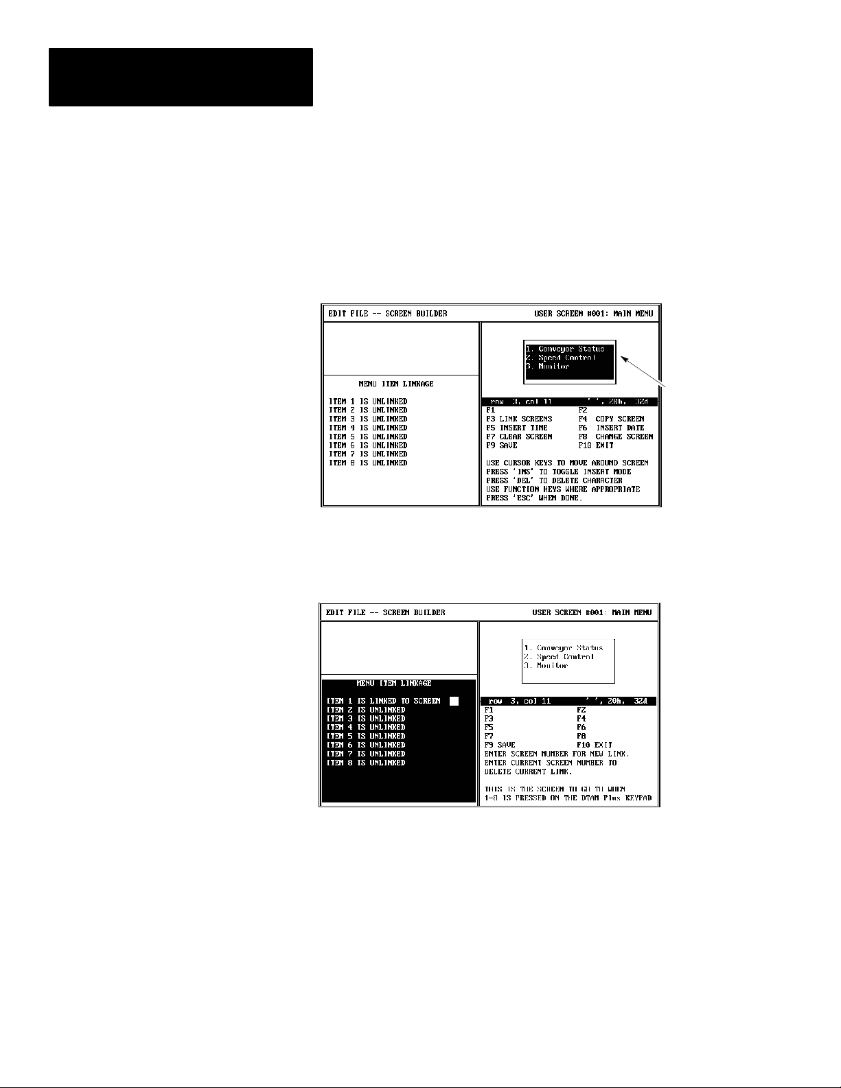
Chapter 12
Linking Menu and Application Screens
Linking a Menu
The following is a typical example of how to link items to a main menu.
Links to a sub-menu are done in the same manner.
To link screens to a menu:
1. Open the menu or sub-menu screen.
Previously
entered text,
refer to Chapter 6
2. Press [F3] to select the link screens function.
You are prompted to enter a screen number.
12–4
3. Enter the screen # you want linked to numeric entry key [1] and
press [Return].
You are prompted to enter the screen linked to DTAM numeric key [2].
4. Continue entering screen links with up to 8 DTAM numeric entry keys.
5. Press [F9] to save the menu edits.
Page 99
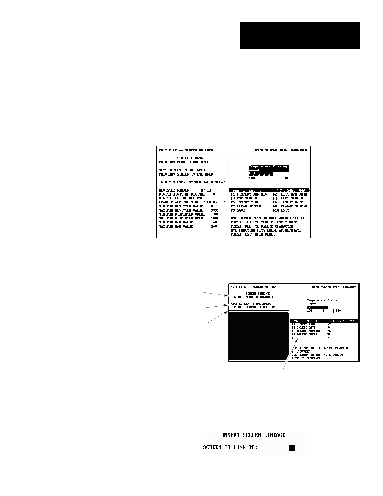
Chapter 12
Linking Menu and Application Screens
Linking Example
The following is an example of how to create one way or bidirectional
screen links.
To link application screens:
1. Open the screen you want to link. In this example we are linking screen
#16 (bar graph display) to screen # 33 (numeric entry screen).
2. Press [F3] to select the MAP Screen function.
The current screen links are displayed along with the screen linking
function key operations.
Indicates that this
screen is not linked
to a menu.
Indicates this screen
is not linked to another.
Indicates that no other
screen is linked to this
screen.
Function key
operations.
3. Press [F1] to create a bidirectional link (operator can move between
screens) or [F3] to create a Goto (one way link, this screen to specified
screen).
You are prompted to enter a screen number.
12–5
Page 100

Chapter 12
Linking Menu and Application Screens
4. Enter a screen number (in this example screen #33) and press [Return].
The screen link is shown in the Screen Linkage description.
5. Press [F9] to save the screen edits.
When you open the screen that was just linked (#33), the Screen Linkage
description will show that there is now a previous screen link to that
screen.
12–6
 Loading...