

Page 1

PowerFlex® 22-COMM-B
BACnet MS/TP Adapter
Firmware Version 1.xxx
User Manual
Page 2
Important User Information
Solid state equipment has operational characteristics differing from those of
electromechanical equipment. Safety Guidelines for the Application, Installation
and Maintenance of Solid State Controls (Publication SGI-1.1 available from your
local Rockwell Automation sales office or online at http://
www.rockwellautomation.com/literature) describes some important differences
between solid state equipment and hard-wired electromechanical devices. Because
of this difference, and also because of the wide variety of uses for solid state
equipment, all persons responsible for applying this equipment must satisfy
themselves that each intended application of this equipment is acceptable.
In no event will Rockwell Automation, Inc. be responsible or liable for indirect or
consequential damages resulting from the use or application of this equipment.
The examples and diagrams in this manual are included solely for illustrative
purposes. Because of the many variables and requirements associated with any
particular installation, Rockwell Automation, Inc. cannot assume responsibility or
liability for actual use based on the examples and diagrams.
No patent liability is assumed by Rockwell Automation, Inc. with respect to use of
information, circuits, equipment, or software described in this manual.
Reproduction of the contents of this manual, in whole or in part, without written
permission of Rockwell Automation, Inc. is prohibited.
Throughout this manual, when necessary we use notes to make you aware of safety
considerations.
WARNING: Identifies information about practices or circumstances
that can cause an explosion in a hazardous environment, which may
!
!
lead to personal injury or death, property damage, or economic loss.
Important: Identifies information that is critical for successful application and
!
!
Allen-Bradley, PowerFlex, DriveExplorer, DriveExecutive, DriveTools SP, and ControlFLASH are trademarks of Rockwell
Automation, Inc.
Trademarks not belonging to Rockwell Automation are property of their respective companies.
understanding of the product.
ATTENTION: Identifies information about practices or circumstances
that can lead to personal injury or death, property damage, or economic
loss. Attentions help you identify a hazard, avoid a hazard, and
recognize the consequences.
Shock Hazard labels may be located on or inside the equipment (e.g.,
drive or motor) to alert people that dangerous voltage may be present.
Burn Hazard labels may be located on or inside the equipment (e.g.,
drive or motor) to alert people that surfaces may be at dangerous
temperatures.
Page 3

Summary of Changes
The information below summarizes the changes made to this manual
since its last release (October 2006):
Description of Changes Page(s)
Updated information in the “Related Documentation” section. P-1
In the “Compatible Products” section, added the PowerFlex 4M drive.
NOTE: The 22-COMM-B adapter must have firmware version 1.003 (or later)
to be compatible with the PowerFlex 4M drive.
Updated information in the “Using the Optional, External PowerFlex 4-Class
HIM” section.
Added the new section “Flash Updating the Adapter.” 3-10
Revised Table 4.A to include the PowerFlex 4M drive. 4-3
1-3
3-2
Page 4

soc-ii Summary of Changes
Page 5

Preface About This Manual
Related Documentation . . . . . . . . . . . . . . . . . . . . . . . . . . . . . P-1
Rockwell Automation Support. . . . . . . . . . . . . . . . . . . . . . . . P-2
Conventions Used in this Manual . . . . . . . . . . . . . . . . . . . . . P-2
Chapter 1 Getting Started
Components . . . . . . . . . . . . . . . . . . . . . . . . . . . . . . . . . . . . . . 1-1
Features . . . . . . . . . . . . . . . . . . . . . . . . . . . . . . . . . . . . . . . . . 1-2
Compatible Products . . . . . . . . . . . . . . . . . . . . . . . . . . . . . . . 1-3
Required Equipment . . . . . . . . . . . . . . . . . . . . . . . . . . . . . . . 1-3
Safety Precautions . . . . . . . . . . . . . . . . . . . . . . . . . . . . . . . . . 1-4
Quick Start . . . . . . . . . . . . . . . . . . . . . . . . . . . . . . . . . . . . . . . 1-6
Status Indicators. . . . . . . . . . . . . . . . . . . . . . . . . . . . . . . . . . . 1-7
Chapter 2 Installing the Adapter
Preparing for an Installation. . . . . . . . . . . . . . . . . . . . . . . . . . 2-1
Commissioning the Adapter. . . . . . . . . . . . . . . . . . . . . . . . . . 2-1
Connecting the Adapter to the Drive . . . . . . . . . . . . . . . . . . . 2-6
Applying Power . . . . . . . . . . . . . . . . . . . . . . . . . . . . . . . . . . . 2-9
Connecting the Drive/Adapter to the Network . . . . . . . . . . 2-11
Chapter 3 Configuring the Adapter
Configuration Tools . . . . . . . . . . . . . . . . . . . . . . . . . . . . . . . . 3-1
Using the Optional, External PowerFlex 4-Class HIM . . . . . 3-2
Setting the Device Instance Number . . . . . . . . . . . . . . . . . . . 3-4
Setting a Comm Loss Action . . . . . . . . . . . . . . . . . . . . . . . . . 3-6
Setting the Comm Loss Time. . . . . . . . . . . . . . . . . . . . . . . . . 3-7
Setting the Baud Rate. . . . . . . . . . . . . . . . . . . . . . . . . . . . . . . 3-8
Resetting the Adapter. . . . . . . . . . . . . . . . . . . . . . . . . . . . . . . 3-9
Viewing the Adapter Status Using Parameters . . . . . . . . . . 3-10
Flash Updating the Adapter . . . . . . . . . . . . . . . . . . . . . . . . . 3-10
Table of Contents
Chapter 4 Using BACnet Objects
Understanding BACnet Objects. . . . . . . . . . . . . . . . . . . . . . . 4-1
Basic Drive Operation on the Network . . . . . . . . . . . . . . . . . 4-2
Supported BACnet Objects . . . . . . . . . . . . . . . . . . . . . . . . . . 4-3
Page 6

ii Table of Contents
Chapter 5 Troubleshooting
Understanding the Status Indicators . . . . . . . . . . . . . . . . . . . 5-1
PORT Status Indicator . . . . . . . . . . . . . . . . . . . . . . . . . . . . . . 5-2
MOD Status Indicator . . . . . . . . . . . . . . . . . . . . . . . . . . . . . . 5-2
NET A Status Indicator . . . . . . . . . . . . . . . . . . . . . . . . . . . . . 5-3
NET B Status Indicator . . . . . . . . . . . . . . . . . . . . . . . . . . . . . 5-3
Viewing Adapter Diagnostic Items . . . . . . . . . . . . . . . . . . . . 5-4
Viewing and Clearing Events. . . . . . . . . . . . . . . . . . . . . . . . . 5-5
Appendix A Specifications
Communications . . . . . . . . . . . . . . . . . . . . . . . . . . . . . . . . . A-1
Electrical . . . . . . . . . . . . . . . . . . . . . . . . . . . . . . . . . . . . . . . A-1
Mechanical . . . . . . . . . . . . . . . . . . . . . . . . . . . . . . . . . . . . . . A-1
Environmental . . . . . . . . . . . . . . . . . . . . . . . . . . . . . . . . . . . A-2
Regulatory Compliance . . . . . . . . . . . . . . . . . . . . . . . . . . . . A-2
Appendix B Adapter Parameters
About Parameter Numbers. . . . . . . . . . . . . . . . . . . . . . . . . . . B-1
Parameter List . . . . . . . . . . . . . . . . . . . . . . . . . . . . . . . . . . . . B-1
Appendix C Protocol Implementation Conformance Statement
(PICS)
Product Description . . . . . . . . . . . . . . . . . . . . . . . . . . . . . . . . C-1
BACnet Standardized Device Profile (Annex L). . . . . . . . . . C-1
List all BACnet Interoperability Building Blocks Supported
(Annex K) . . . . . . . . . . . . . . . . . . . . . . . . . . . . . . . . . . . . C-1
Segmentation Capability . . . . . . . . . . . . . . . . . . . . . . . . . . . . C-1
Standard Object Types Supported . . . . . . . . . . . . . . . . . . . . . C-2
Data Link Layer Options . . . . . . . . . . . . . . . . . . . . . . . . . . . . C-3
Device Address Binding . . . . . . . . . . . . . . . . . . . . . . . . . . . . C-3
Networking Options. . . . . . . . . . . . . . . . . . . . . . . . . . . . . . . . C-3
Appendix D Routing Capability for Networked Drives
Glossary
Index
Page 7

Preface
About This Manual
Topic Page
Related Documentation
Rockwell Automation Support P-2
Conventions Used in this Manual P-2
Related Documentation
For: Refer to: Publication
DriveExplorer™ http://www.ab.com/drives/driveexplorer, and
DriveTools™ SP (includes
DriveExecutive™)
PowerFlex 4-Class HIM
(22-HIM-A3 or 22-HIM-C2S)
Powe rFlex
Powe rFlex
Powe rFlex
Powe rFlex
(1)
The 22-COMM-B adapter must have firmware version 1.003 (or later) to be compatible with the PowerFlex 4M
drive.
®
4 Drive PowerFlex 4 User Manual
®
4M Drive
®
40 Drive PowerFlex 40 User Manual
®
400 Drive PowerFlex 400 User Manual
DriveExplorer online Help (installed with the software)
http://www.ab.com/drives/drivetools, and
DriveExecutive online Help (installed with the software)
HIM Quick Reference 22HIM-QR001
PowerFlex 4 Quick Start
(1)
PowerFlex 4M User Manual
PowerFlex 4M Quick Start
PowerFlex 40 Quick Start
PowerFlex 400 Quick Start
P-1
—
—
22A-UM001
22A-QS001
22F-UM001
22F-QS001
22B-UM001
22B-QS001
22C-UM001
22C-QS001
You can view or download publications at http://
www.rockwellautomation.com/literature. To order paper copies of
technical documentation, contact your local Rockwell Automation
distributor or sales representative.
To find your Rockwell Automation distributor or sales representative,
visit www.rockwellautomation.com/locations
For information such as firmware updates or answers to drive-related
questions, go to the Drives Service & Support web site at www.ab.com/
support/abdrives and click on the “Downloads” or “Knowledgebase”
link.
.
Page 8

P-2 About This Manual
Rockwell Automation Support
Rockwell Automation, Inc. offers support services worldwide, with over
75 sales/support offices, over 500 authorized distributors, and over 250
authorized systems integrators located throughout the United States
alone. In addition, Rockwell Automation, Inc. representatives are in
every major country in the world.
Local Product Support
Contact your local Rockwell Automation, Inc. representative for:
• Sales and order support
• Product technical training
• Warranty support
• Support service agreements
Technical Product Assistance
For technical assistance, please review the information in Chapter 5,
Troubleshooting first. If you still have problems, then access the
Allen-Bradley Technical Support web site at www.ab.com/support/
abdrives or contact Rockwell Automation, Inc.
Conventions Used in this Manual
This manual provides information about the adapter and using it with
PowerFlex 4-Class drives. The adapter can be used with other products
that support a DSI™ adapter, such as the DSI External Comms Kit
(22-XCOMM-DC-BASE). Refer to the documentation for your product
for specific information about how it works with the adapter.
The following conventions are used throughout this manual:
• Parameter names are shown in the format Parameter xx - [*]. The xx
represents the parameter number, and the * represents the parameter
name—for example, Parameter 01 - [Mode].
• Menu commands are shown in bold type face and follow the format
Menu > Command. For example, if you read “Select File > Open,”
you should click the File menu and then click the Open command.
• The firmware release is displayed as FRN X.xxx. The “FRN”
signifies Firmware Release Number. The “X” is the major release
number. The “xxx” is the minor update number.
Page 9
Chapter 1
Getting Started
The adapter is intended for installation into a PowerFlex 40 or
PowerFlex 400 drive and is used for network communication. The
adapter can also be installed in a DSI External Comms Kit
(22-XCOMM-DC-BASE). This kit enables PowerFlex 4 and PowerFlex
4M drives, which cannot accommodate an internally-mounted adapter,
to connect to a BACnet MS/TP network. NOTE: The 22-COMM-B
adapter must have firmware version 1.003 (or later) to be compatible
with the PowerFlex 4M drive.
Topic Page Topic Page
Components
Features 1-2 Quick Start 1-6
Compatible Products 1-3 Status Indicators 1-7
Required Equipment 1-3
1-1 Safety Precautions 1-4
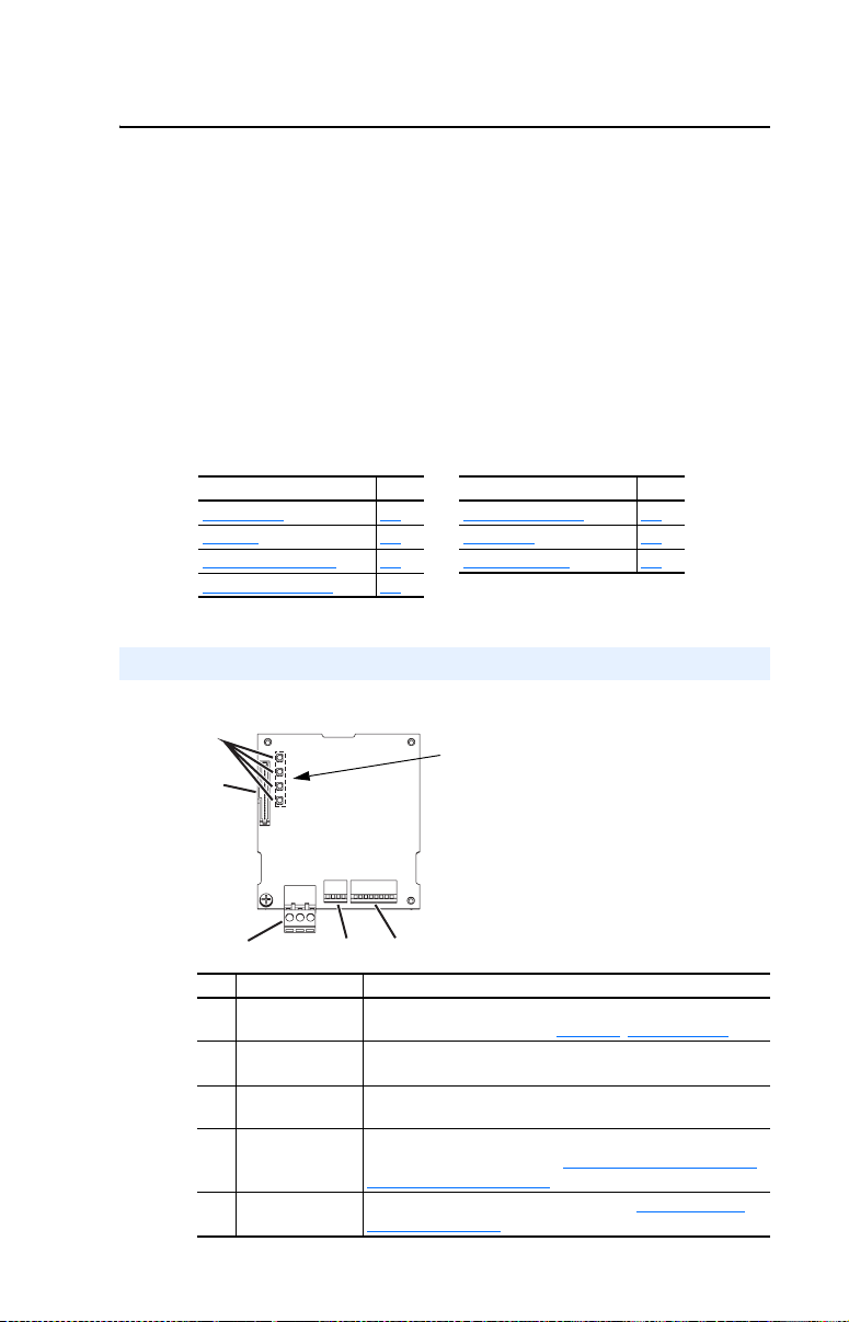
Components
Figure 1.1 Components of the Adapter
➊
➋
LEDs are located
on bottom side of
adapter board
➌
Item Component Description
Status Indicators Four LEDs that indicate the status of the network connection,
➊
DSI Connector A 20-pin, single-row shrouded male header. An Internal Interface
➋
Terminal Block A 3-pin terminal block with mating 3-pin linear plug connects the
➌
TERM, -BIAS, and
➍
+BIAS Switches
MAC Address
➎
Switches
➍
➎
DSI, and the adapter. Refer to Chapter 5
cable connects to this connector and a connector on the drive.
adapter to the network.
Switches for turning on/off the adapter’s internal termination
resistor and bias resistors. See Setting the TERM, -BIAS, and
+BIAS Switches on page 2-4 for details.
Switches for setting the MAC address. See Setting the MAC
Address on page 2-2 for details.
, Troubleshooting.
Page 10

1-2 Getting Started
Features
The adapter features include:
• Typical mounting in a PowerFlex 40 or PowerFlex 400 drive. The
adapter can also be installed in a DSI External Comms Kit
(22-XCOMM-DC-BASE).
• Switches that enable you to:
– Set a MAC address before applying power to the drive.
– Turn on/off the adapter’s built-in termination resistor and bias
resistors for optimizing operation on the network.
• A captive screw secures and grounds the adapter to the drive or,
when mounted in a DSI External Comms Kit, to the kit’s metal
enclosure.
• Compatibility with various configuration tools to configure the
adapter and connected drive. The tools include an external
PowerFlex 4-Class HIM (22-HIM-A3 or 22-HIM-C2S), and
drive-configuration software such as DriveExplorer (version 3.01 or
later) or DriveExecutive (version 3.01 or later).
• Status indicators that report the status of drive communications, the
adapter, and network.
• Read and write access to parameters to configure and monitor
parameter values over the network.
• User-defined fault actions to determine how the adapter and
connected drive respond to I/O communication disruptions (Comm
Loss Action) on the network.
Page 11

Getting Started 1-3
Compatible Products
The adapter is compatible with Allen-Bradley PowerFlex 4-Class
(Component-Class) drives and other products that support an internal
DSI adapter. At the time of publication, compatible products include:
• PowerFlex 4 drives (when used with DSI External Comms Kit)
• PowerFlex 4M drives
• PowerFlex 40 drives
• PowerFlex 400 drives
(1)
The 22-COMM-B adapter must have firmware version 1.003 (or later) to be compatible with
PowerFlex 4M drives.
Required Equipment
Equipment Shipped with the Adapter
When you unpack the adapter, verify that the package includes:
❑ One adapter
❑ One 15.24 cm (6 in.) Internal Interface cable
❑ One 3-pin linear plug (plugged into the adapter socket)
❑ One PowerFlex 4-Class DSI (Drive Serial Interface) Network
Communications Adapter Installation Instructions (publication
22COMM-IN002)
(1)
(when used with DSI External Comms Kit)
User-Supplied Equipment
To install and configure the adapter, you must supply:
❑ A small flathead screwdriver
❑ A shielded, twisted wire pair to connect the adapter to the network
❑ A configuration tool, such as:
– PowerFlex 4-Class HIM (22-HIM-A3 or 22-HIM-C2S) – required
to access adapter parameters when not using DriveExplorer or
DriveExecutive software
– DriveExplorer software (version 3.01 or later)
– DriveExecutive stand-alone software (version 3.01 or later) or
bundled with the DriveTools SP suite (version 1.01 or later)
– Third-party network configuration software
Page 12
1-4 Getting Started
Safety Precautions
Please read the following safety precautions carefully.
ATTENTION: Risk of injury or death exists. The PowerFlex drive
may contain high voltages that can cause injury or death. Remove
!
power from the PowerFlex drive, and then verify power has been
discharged before installing or removing an adapter.
ATTENTION: Risk of injury or equipment damage exists. Only
personnel familiar with drive and power products and the associated
!
machinery should plan or implement the installation, start-up,
configuration, and subsequent maintenance of the product using an
adapter. Failure to comply may result in injury and/or equipment
damage.
ATTENTION: Risk of equipment damage exists. The adapter
contains ESD (Electrostatic Discharge) sensitive parts that can be
!
damaged if you do not follow ESD control procedures. Static control
precautions are required when handling the adapter. If you are
unfamiliar with static control procedures, refer to Guarding Against
Electrostatic Damage (publication 8000-4.5.2).
ATTENTION: Risk of injury or equipment damage exists. If the
adapter is transmitting control I/O to the drive, the drive may fault when
!
you reset the adapter. Determine how your drive will respond before
resetting an adapter.
ATTENTION: Risk of injury or equipment damage exists.
Parameter 02 - [Comm Loss Action] lets you determine the action of
!
the adapter and connected drive if communications are disrupted. By
default, this parameter faults the drive. You can set this parameter so
that the drive continues to run. Precautions should be taken to ensure
that the setting of this parameter does not create a risk of injury or
equipment damage. When commissioning the drive, verify that your
system responds correctly to various situations (for example, a
disconnected cable).
ATTENTION: Risk of injury or equipment damage exists. Parameter
03 - [Comm Loss Time] lets you determine how long it will take the
!
adapter to detect network communication losses. By default, this
parameter sets the timeout to ten seconds. You can set it so that the
duration is shorter, longer, or disabled. When set to disabled, this also
disables adapter Parameter 02 - [Comm Loss Action]. Therefore, a
communications fault action will be ignored. Take precautions to ensure
that the setting does not create a risk of injury or equipment damage.
When commissioning the drive, verify that your system responds
correctly to various situations (for example, a disconnected cable).
Page 13

Getting Started 1-5
ATTENTION: Risk of injury or equipment damage exists. When a
system is configured for the first time, there may be unintended or
!
incorrect machine motion. Disconnect the motor from the machine or
process during initial system testing.
ATTENTION: Risk of injury or equipment damage exists. The
examples in this publication are intended solely for purposes of
!
example. There are many variables and requirements with any
application. Rockwell Automation, Inc. does not assume responsibility
or liability (to include intellectual property liability) for actual use of
the examples shown in this publication.
Page 14

1-6 Getting Started
Quick Start
This section is provided to help experienced users quickly start using the
adapter. If you are unsure how to complete a step, refer to the referenced
chapter.
Step Action Refer to …
1 Review the safety precautions for the adapter. Throughout this manual
2 Verify that the PowerFlex drive is properly installed. Drive User Manual
3 Commission the adapter.
Set a unique MAC address and, depending on where the
PowerFlex drive nodes are located on the network,
appropriately set the TERM, -BIAS, and +BIAS switches.
4 Install the adapter.
Verify that the PowerFlex drive is not powered. Then,
connect the adapter to the drive using the Internal
Interface cable. Use the captive screw to secure and
ground the adapter to the drive.
When installing the adapter in a DSI External Comms Kit,
refer to the 22-XCOMM-DC-BASE Installation Instructions
(publication 22COMM-IN001) supplied with the kit.
5 Apply power to the adapter and verify key settings.
A. The adapter receives power from the drive. Verify
that the adapter is installed correctly and then apply
power to the drive. The PORT status indicator should
be solid green. If it is red, there is a problem. Refer to
Chapter 5
B. Verify/configure key adapter parameters.
C. Configure/verify key drive parameters.
6 Connect the adapter to the network.
Verify that the PowerFlex drive is not powered. Then,
connect the adapter to the network using a shielded,
twisted wire pair.
7 Configure the adapter for your application.
Set adapter parameters for the following functions as
required by your application:
• Fault actions
• Baud rate
8 Configure the controller to communicate with the
adapter.
Use the controller’s programming software to program the
controller.
, Troubleshooting.
Chapter 2
,
Installing the Adapter
PowerFlex 4-Class DSI
Network Communication
Adapter Installation
Instructions (publication
22COMM-IN002) and
Chapter 2
,
Installing the Adapter
,
Chapter 2
Installing the Adapter
Chapter 2,
Installing the Adapter
Chapter 3,
Configuring the Adapter
Instructions for your
controller’s programming
software
Page 15
Getting Started 1-7
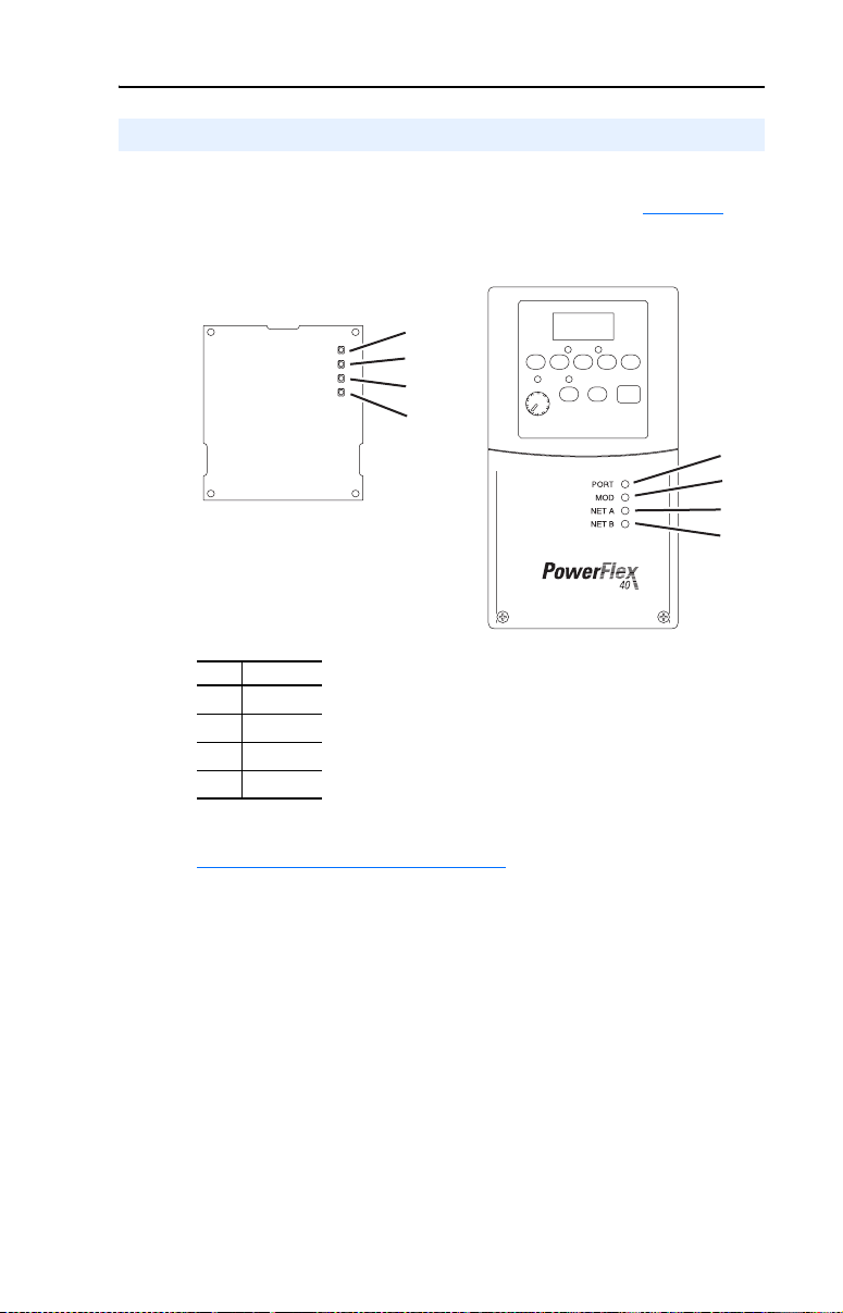
Status Indicators
The adapter uses four status indicators to report its operating status. They
can be viewed on the adapter or through the drive cover (Figure 1.2
Figure 1.2 Status Indicators (location on drive may vary)
➊
➋
➌
➍
Bottom side
of adapter board
).
➊
➋
➌
➍
Item Name
PORT
➊
MOD
➋
NET A
➌
NET B
➍
After installing the adapter and applying power to the drive, refer to
Start-Up Status Indications
indications and their descriptions.
on page 2-9 for possible start-up status
Page 16

1-8 Getting Started
Notes:
Page 17

Chapter 2
Installing the Adapter
This chapter provides instructions for installing the adapter in a
PowerFlex 40 or PowerFlex 400 drive. This adapter can also be installed
in a DSI External Comms Kit. In this case, refer to the
22-XCOMM-DC-BASE Installation Instructions (publication
22COMM-IN001) supplied with the kit.
Topic Page
Preparing for an Installation
Commissioning the Adapter 2-1
Connecting the Adapter to the Drive 2-6
Applying Power 2-9
Connecting the Drive/Adapter to the Network 2-11
2-1
Preparing for an Installation
Before installing the adapter, verify that you have all required
equipment. Refer to Required Equipment
on page 1-3.
Commissioning the Adapter
To commission the adapter, you must set a unique MAC address and,
depending on where the PowerFlex drive node is located on the network
(starting and ending network nodes versus all other node locations),
appropriately set the TERM, -BIAS, and +BIAS switches.
Important: New settings are recognized only when power is applied to
the adapter or it is reset. If you change a switch setting,
cycle power or reset the adapter to apply the change.
ATTENTION: Risk of equipment damage exists. The adapter
contains ESD (Electrostatic Discharge) sensitive parts that can be
!
damaged if you do not follow ESD control procedures. Static control
precautions are required when handling the adapter. If you are
unfamiliar with static control procedures, refer to Guarding Against
Electrostatic Damage (publication 8000-4.5.2).
Page 18
2-2 Installing the Adapter
Setting the MAC Address
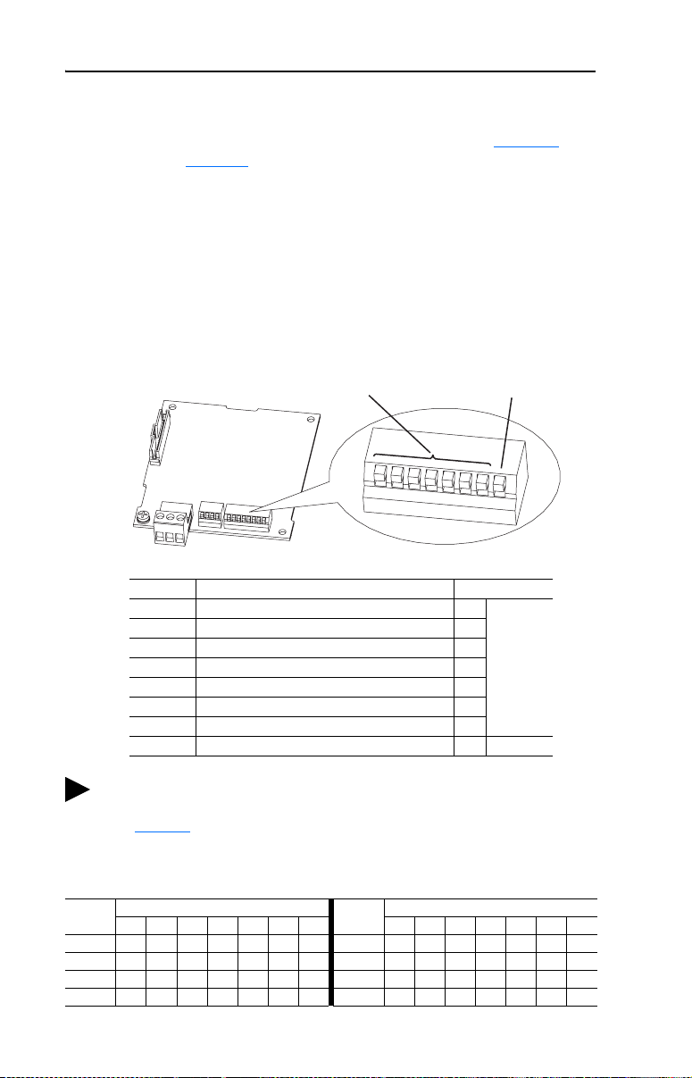
Set the MAC address using the MAC Address switches (Figure 2.1).
Refer to Table 2.A for specific MAC address switch settings.
Important: Each node on the network must have a unique MAC
address. Set the MAC address before power is applied
because the adapter uses the MAC address it detects when it
first receives power. To change a MAC address, you must
set the new value. Then remove and reapply power to (or
reset) the adapter.
Figure 2.1 Setting the Adapter MAC Address Switches
MAC Address Switches
(SW1…SW7)
Switches Description Default
SW1 Least Significant Bit (LSB) of MAC Address 0
SW2 Bit 1 of MAC Address 0
SW3 Bit 2 of MAC Address 0
SW4 Bit 3 of MAC Address 0
SW5 Bit 4 of MAC Address 0
SW6 Bit 5 of MAC Address 0
SW7 Most Significant Bit (MSB) of MAC Address 0
SW8 Mode (reserved for future use) — —
TIP: The MAC address switch settings can be verified by viewing
Parameter 08 - [MAC Address] or Diagnostic Item number 12
(page 5-4
DriveExplorer software, or DriveExecutive software.
Table 2.A MAC Address Switch Settings (UP = 1 = OPEN)
Address
MAC
SW1 SW2 SW3 SW4 SW5 SW6 SW7
0 0000000
1 1000000
2 0100000
3 1100000
) using an optional, external PowerFlex 4-Class HIM,
Switch Setting
MAC
Address
4 0010000
5 1010000
6 0110000
7 1110000
Mode Switch (SW8)
Reserved for future use
1
2
3
4
5
6
7
8
UP = 1 = OPEN
Node 0
Switch Setting
SW1 SW2 SW3 SW4 SW5 SW6 SW7
Page 19

Installing the Adapter 2-3
Table 2.A MAC Address Switch Settings (UP = 1 = OPEN) (Continued)
MAC
Address
SW1 SW2 SW3 SW4 SW5 SW6 SW7
8 0 0 0 1 0 0 0 56 0 0 0 1 1 1 0
9 1 0 0 1 0 0 0 57 1 0 0 1 1 1 0
10 0 1 0 1 0 0 0 58 0 1 0 1 1 1 0
11 1 1 0 1 0 0 0 59 1 1 0 1 1 1 0
12 0011000
13 1011000
14 0111000
15 1111000
16 0 0 0 0 1 0 0 64 0 0 0 0 0 0 1
17 1 0 0 0 1 0 0 65 1 0 0 0 0 0 1
18 0 1 0 0 1 0 0 66 0 1 0 0 0 0 1
19 1 1 0 0 1 0 0 67 1 1 0 0 0 0 1
20 0010100
21 1010100
22 0110100
23 1110100
24 0 0 0 1 1 0 0 72 0 0 0 1 0 0 1
25 1 0 0 1 1 0 0 73 1 0 0 1 0 0 1
26 0 1 0 1 1 0 0 74 0 1 0 1 0 0 1
27 1 1 0 1 1 0 0 75 1 1 0 1 0 0 1
28 0011100
29 1011100
30 0111100
31 1111100
32 0 0 0 0 0 1 0 80 0 0 0 0 1 0 1
33 1 0 0 0 0 1 0 81 1 0 0 0 1 0 1
34 0 1 0 0 0 1 0 82 0 1 0 0 1 0 1
35 1 1 0 0 0 1 0 83 1 1 0 0 1 0 1
36 0010010
37 1010010
38 0110010
39 1110010
40 0 0 0 1 0 1 0 88 0 0 0 1 1 0 1
41 1 0 0 1 0 1 0 89 1 0 0 1 1 0 1
42 0 1 0 1 0 1 0 90 0 1 0 1 1 0 1
43 1 1 0 1 0 1 0 91 1 1 0 1 1 0 1
44 0011010
45 1011010
46 0111010
47 1111010
48 0 0 0 0 1 1 0 96 0 0 0 0 0 1 1
49 1 0 0 0 1 1 0 97 1 0 0 0 0 1 1
50 0 1 0 0 1 1 0 98 0 1 0 0 0 1 1
51 1 1 0 0 1 1 0 99 1 1 0 0 0 1 1
52 0010110
53 1010110
54 0110110
55 1110110
Switch Setting
MAC
Address
SW1 SW2 SW3 SW4 SW5 SW6 SW7
60 0011110
61 1011110
62 0111110
63 1111110
68 0010001
69 1010001
70 0110001
71 1110001
76 0011001
77 1011001
78 0111001
79 1111001
84 0010101
85 1010101
86 0110101
87 1110101
92 0011101
93 1011101
94 0111101
95 1111101
100 0010011
101 1010011
102 0110011
103 1110011
Switch Setting
Page 20
2-4 Installing the Adapter
Table 2.A MAC Address Switch Settings (UP = 1 = OPEN) (Continued)
MAC
Address
SW1 SW2 SW3 SW4 SW5 SW6 SW7
104 0 0 0 1 0 1 1 116 0 0 1 0 1 1 1
105 1 0 0 1 0 1 1 117 1 0 1 0 1 1 1
106 0 1 0 1 0 1 1 118 0 1 1 0 1 1 1
107 1 1 0 1 0 1 1 119 1 1 1 0 1 1 1
108 0011011
109 1011011
110 0111011
111 1111011
112 0 0 0 0 1 1 1 124 0 0 1 1 1 1 1
113 1 0 0 0 1 1 1 125 1 0 1 1 1 1 1
114 0 1 0 0 1 1 1 126 0 1 1 1 1 1 1
115 1 1 0 0 1 1 1 127 1 1 1 1 1 1 1
Switch Setting
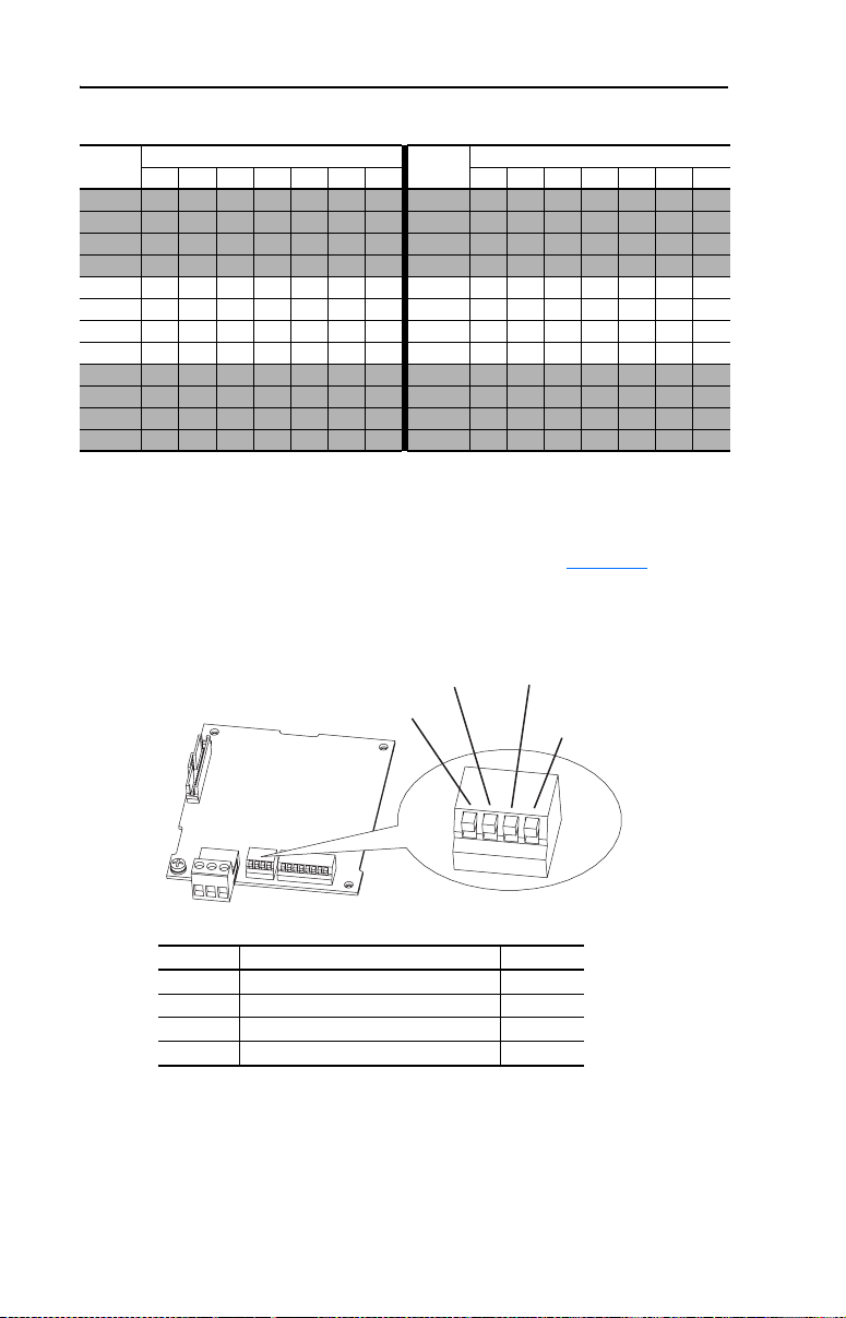
Setting the TERM, -BIAS, and +BIAS Switches
The adapter’s TERM, -BIAS, and +BIAS switches (Figure 2.2) are used
to turn on/off its built-in termination resistor and bias resistors.
MAC
Address
SW1 SW2 SW3 SW4 SW5 SW6 SW7
120 0001111
121 1001111
122 0101111
123 1101111
Switch Setting
Figure 2.2 Setting the TERM, -BIAS, and +BIAS Switches
-BIAS Switch (SW2) +BIAS Switch (SW3)
TERM Switch (SW1)
RSRV Switch (SW4)
Reserved for future use
1
2
3
4
Switches Description Default
SW1 Turns on/off the termination resistor Up (Off)
SW2 Turns on/off the -bias resistor Up (Off)
SW3 Turns on/off the +bias resistor Up (Off)
SW4 Reserved (not used) —
Since nodes on a BACnet MS/TP network are typically a mix of
Allen-Bradley PowerFlex drives and other brands of building automation
products, the network node locations for the PowerFlex drives will
determine how their adapter’s TERM, -BIAS, and +BIAS switches
should be set.
UP = OFF
Page 21
Installing the Adapter 2-5
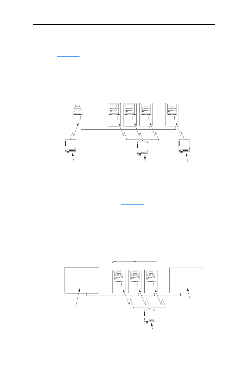
Network with PowerFlex Drives at Starting and/or Ending Nodes
For a network with PowerFlex drives at the starting and/or ending nodes
(Figure 2.3
switches to the “Down” (On) position. All other PowerFlex drive
network nodes must have these switches set to the “Up” (Off) position.
Figure 2.3 Example Network with PowerFlex Drives at Starting and/or Ending Nodes
), set their 22-COMM-B adapter’s TERM, -BIAS, and +BIAS
Node 1
(Starting Node)
BACnet MS/TP Network
22-COMM-B Adapter Settings for
TERM, -BIAS, and +BIAS Switches
"Down" (On) Positions
Node 2 Node 3 Node 4
"Up" (Off) Positions
Node
(Ending Node)
■ ■ ■
"Down" (On) Positions
n
Network with PowerFlex Drives at Other Nodes
For a network with PowerFlex drives at other node locations—not
starting and/or ending nodes (Figure 2.4), set their 22-COMM-B
adapter’s TERM, -BIAS, and +BIAS switches to the “Up” (Off)
position. In this network scenario, other brands of building automation
products at the starting and/or ending nodes require appropriate
termination and bias resistors. Refer to their documentation for details.
Figure 2.4 Example Network with PowerFlex Drives at Other Nodes
Node 1
(Starting Node)
Other Brand
Building Automation
Product
PowerFlex 4-Class Drives
Node 2 Node 3 Node 4
(Ending Node)
Other Brand
Building Automation
■ ■ ■
n
Node
Product
BACnet MS/TP Network
Requires
Termination and
Bias Resistors
22-COMM-B Settings
for TERM, -BIAS, and
+BIAS Switches
Requires
Termination and
Bias Resistors
"Up" (Off) Positions
Page 22
2-6 Installing the Adapter
Connecting the Adapter to the Drive
PowerFlex 40 Frames B and C, and PowerFlex 400 Frame C
1. Remove power from the drive, and remove the drive cover.
2. Use static control precautions.
3. Mount the adapter on the required special drive cover (ordered
separately; see Figure 2.5 for part numbers).
• Frame B: Do not use the adapter screw; snap the adapter in place.
• Frame C: Use the adapter screw to secure the adapter to the cover.
Important: To properly ground the adapter in Frame B drives,
install the special drive cover onto the drive using both
cover fasteners. To ground the adapter in Frame C
drives, tighten the adapter’s lower left screw (see
Figure 2.5
recommended torque (0.9 N•m / 8.0 lb•in).
Figure 2.5 Mounting and Grounding the Adapter – PowerFlex 40 Frames B and C,
and PowerFlex 400 Frame C
). In either case, tighten the screw(s) to the
Adapter Mounted on Back of
Required Special Drive Cover
(Frame C cover shown)
PowerFlex 40 Drive (Frame C
shown with cover removed)
0.9 N
(8.0 lb
PowerFlex 40 Frame B -- Part Number 22B-CCB
PowerFlex 40 Frame C -- Part Number 22B-CCC
PowerFlex 400 Frame C -- Part Number 22C-CCC
•
m
•
in)
Ground for Frame C Drives
For Frame B drives, the lower left
NOTE:
adapter screw does not ground the adapter.
To ground the adapter, install the special drive
cover onto the drive using both cover fasteners.
Page 23
Installing the Adapter 2-7
r
4. Connect the Internal Interface cable to the DSI port on the drive and
then to the mating DSI connector on the adapter.
Figure 2.6 Connecting DSI Ports with Internal Interface Cable
➊
22-COMM-B
➋
Adapter
Back of Required
Special Drive Cove
PowerFlex 40 Drive (Frame C
shown with cover removed)
Item Description
DSI connector
➊
15.24 cm (6 in.) Internal Interface cable
➋
Shielded, twisted wire pair for network connection
➌
➌
Page 24
2-8 Installing the Adapter
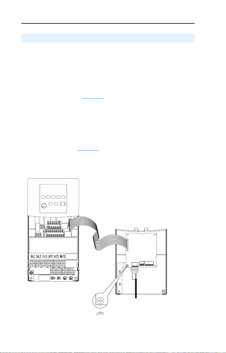
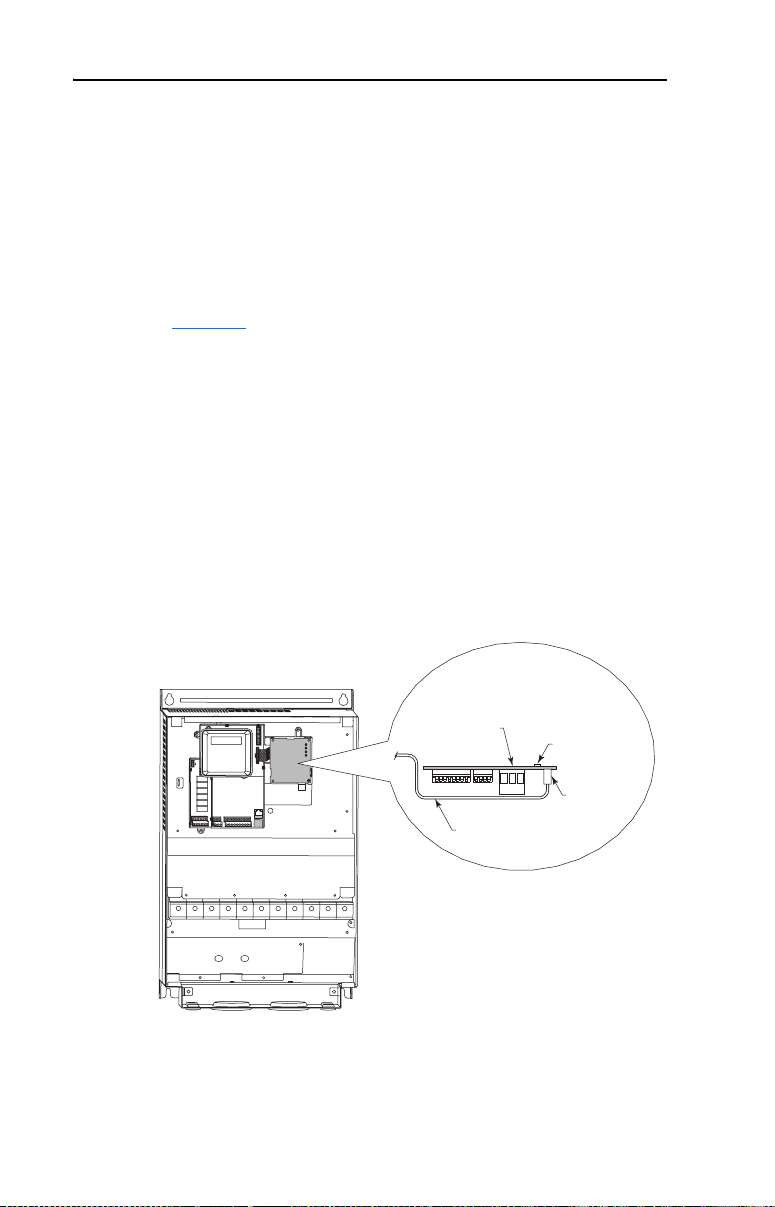
PowerFlex 400 Frames D, E, and F
1. Remove power from the drive, and open the drive cover.
2. Use static control precautions.
3. With the adapter board right side up, remove its mounting screw
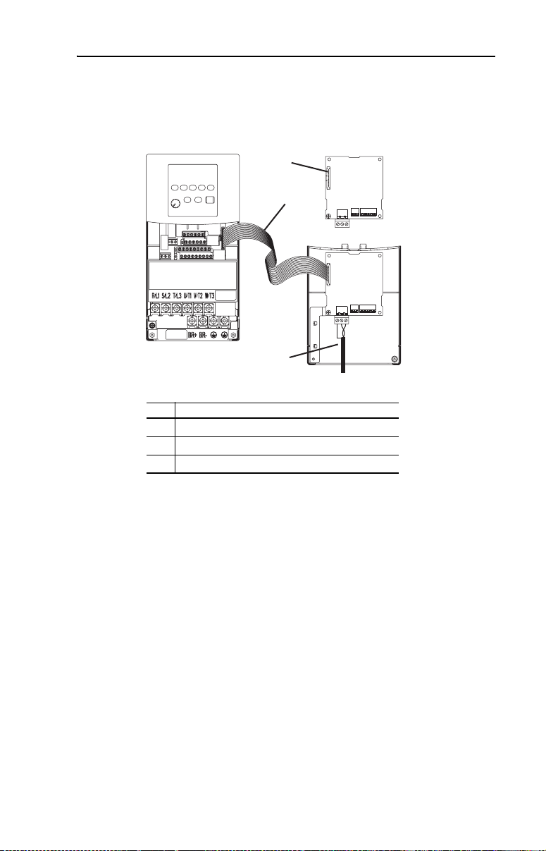
from the lower left hole. Save the screw for mounting in Step 6.
4. Connect the Internal Interface cable to the DSI port on the drive (see
Figure 2.7
5. With the adapter board oriented bottom side up, route the Internal
Interface cable under the adapter, and then to the mating DSI
connector on the adapter.
6. Install the adapter, bottom side up, to the right side of the display
board by snapping it into place. Then insert the adapter mounting
screw into the lower left hole on the board.
Important: Tighten the mounting screw in the adapter’s lower left
Figure 2.7 Mounting and Connecting the Adapter – PowerFlex 400 Frames D, E, and F
).
hole to the recommended torque (0.9 N•m/8.0 lb•in) to
ground the adapter to the drive.
PowerFlex 400
(Frame D shown
with cover removed)
Adapter Installation
(Side View)
Bottom of
Adapter Board
Internal Interface
Ribbon Cable
LEDs
Connector
Page 25

Installing the Adapter 2-9
Applying Power
ATTENTION: Risk of equipment damage, injury, or death exists.
Unpredictable operation may occur if you fail to verify that parameter
!
settings and switch settings are compatible with your application.
Verify that settings are compatible with your application before
applying power to the drive.
Apply power to the drive. The adapter receives its power from the
connected drive. When you apply power to the adapter for the first time,
its topmost status indicator “PORT” should be solid green after an
initialization. If it is red, there is a problem. Refer to Chapter 5
Troubleshooting.
Start-Up Status Indications
Status indicators for the drive and communications adapter can be
viewed on the front of the drive (Figure 2.8
applied. Possible start-up status indications are shown in Table 2.B.
Figure 2.8 Drive and Adapter Status Indicators (location on drive may vary)
) after power has been
,
➊
➋
Page 26

2-10 Installing the Adapter
Table 2.B Drive and Adapter Start-Up Status Indications
Item Name Color State Description
FAULT Red Off Drive ready but not running, and no faults are present.
➊
PORT Green Flashing Normal Operation. The adapter is establishing
➋
MOD Green Flashing Normal Operation. The adapter is operating but is not
NET A Green Flashing Normal Operation. The adapter is properly connected and
NET B Green Off Normal Operation. The adapter is properly connected but is
Verifying/Setting Key Adapter Parameters
For instructions to use an optional PowerFlex 4-Class HIM to access
adapter parameters, see Using the Optional, External PowerFlex 4-Class
HIM on page 3-2.
Drive FAULT Status Indicator
Flashing A fault has occurred.
Adapter Status Indicators
communications with the drive. It will turn solid green or red.
Steady Normal Operation. The adapter is properly connected and
communicating with the drive
transferring I/O data.
Steady Normal Operation. The adapter is operating and transmitting
I/O data.
communicating on the network.
idle.
Flashing Normal Operation. The adapter is transmitting data.
1. Verify that adapter Parameter 08 - [MAC Address] is reporting the
MAC address set in Setting the MAC Address on page 2-2.
2. Set adapter Parameters 11 - [Device Inst Hi] and 12 - [Device Inst
Lo] to establish a unique number for representation to the Building
Automation Controller. For more information, see Setting the Device
Instance Number on page 3-4.
3. Reset the adapter by setting adapter Parameter 01 - [Reset Module]
to “1” (Reset Module) to apply the new Device Instance Number.
Configuring/Verifying Key Drive Parameters
The PowerFlex 4-Class drive can be separately configured for the control
and reference functions in various combinations. For example, you
could set the drive to have its control come from a peripheral or terminal
block with the reference coming from the BACnet MS/TP network. Or
you could set the drive to have its control come from the BACnet MS/TP
network with the reference coming from another peripheral or terminal
block. Or you could set the drive to have both its control and reference
come from the BACnet MS/TP network.
Page 27

Installing the Adapter 2-11
The following steps in this section assume that the drive will receive the
Logic Command and Reference from the BACnet MS/TP network.
1. Using drive Parameter P038 - [Speed Reference], set the drive
speed Reference to “5” (Comm Port).
2. Verify that drive Parameter P036 - [Start Source] is reporting that the
source of the Reference to the drive is “5” (Comm Port). This ensures
that any Reference commanded from the network can be monitored by
using drive Parameter d002 - [Commanded Freq]. If a problem
occurs, this verification step provides the diagnostic capability to
determine whether the drive/adapter or the network is the cause.
Connecting the Drive/Adapter to the Network
ATTENTION: Risk of injury or death exists. The PowerFlex drive
may contain high voltages that can cause injury or death. Remove
!
power from the drive, and then verify power has been discharged
before installing or removing an adapter.
1. Remove power from the drive.
2. Use static control precautions.
3. Connect one end of a shielded, twisted wire pair to the network.
4. Route the other end of the twisted wire pair through the bottom of the
drive (see Figure 2.5
the 3-pin linear plug (provided with the adapter). See Figure 2.9 for
terminal designations and typical terminal connections.
Figure 2.9 Typical Network Terminal Connections
Node 1 Node 2 Node "n"
-A
+B
SHLD
). Connect the twisted wire pair and its shield to
SHLD
-A
SHLD
+B
-A
+B
…
…
…
Terminal Signal Function
SHLD Termination Shield Termination
+B Signal B TxRxD+
-A Signal A TxRxD-
Page 28

2-12 Installing the Adapter
5. Insert the 3-pin linear plug into the mating adapter socket.
6. Close or install the drive cover.
7. Apply power to the drive.
8. Verify that adapter Parameter 07 - [Baud Rate Act] is reporting the
actual network baud rate. If not, use Parameter 06 - [Baud Rate
Cfg] to set the adapter to a fixed baud rate that matches the network
baud rate.
TIP: After the drive is connected and communicating on the BACnet
MS/TP network, it may be necessary to set additional adapter parameters
to meet your application requirements (for example Parameters 02 -
[Comm Loss Action] or 03 - [Comm Loss Time]).
For instructions to use an optional PowerFlex 4-Class HIM to access
adapter parameters, see Using the Optional, External PowerFlex 4-Class
HIM on page 3-2.
Page 29

Chapter 3
Configuring the Adapter
This chapter provides information and instructions for setting the
parameters in the adapter.
Topic Page
Configuration Tools
Using the Optional, External PowerFlex 4-Class HIM 3-2
Setting the Device Instance Number 3-4
Setting a Comm Loss Action 3-6
Setting the Comm Loss Time 3-7
Setting the Baud Rate 3-8
Resetting the Adapter 3-9
Viewing the Adapter Status Using Parameters 3-10
Flash Updating the Adapter 3-10
3-1
For a list of parameters, refer to Appendix B, Adapter Parameters. For
definitions of terms in this chapter, refer to the Glossary.
Configuration Tools
The adapter stores parameters and other information in its own
Non-Volatile Storage (NVS) memory. You must, therefore, access the
adapter to view and edit its parameters. The following tools can be used
to access the adapter parameters:
Tool Refer to…
PowerFlex 4-Class HIM
(22-HIM-A3 or 22-HIM-C2S)
DriveExplorer Software
(version 3.01 or later)
DriveExecutive Software
(version 3.01 or later)
page 3-2
http://www.ab.com/drives/driveexplorer, and
DriveExplorer online help (installed with the software)
http://www.ab.com/drives/drivetools
DriveExecutive online help (installed with the software)
, and
Page 30

3-2 Configuring the Adapter
Using the Optional, External PowerFlex 4-Class HIM
Adapter parameters cannot be accessed using the integral keypad on a
PowerFlex 4-Class drive. You must use DriveExplorer or DriveExecutive
software, or an optional, external PowerFlex 4-Class HIM (22-HIM-A3
or 22-HIM-C2S). See Figure 3.1
parameters in the adapter using the external HIM are shown in
Table 3.A
4-Class HIM Quick Reference (publication 22HIM-QR001).
Table 3.A Accessing Adapter Parameters Using the HIM
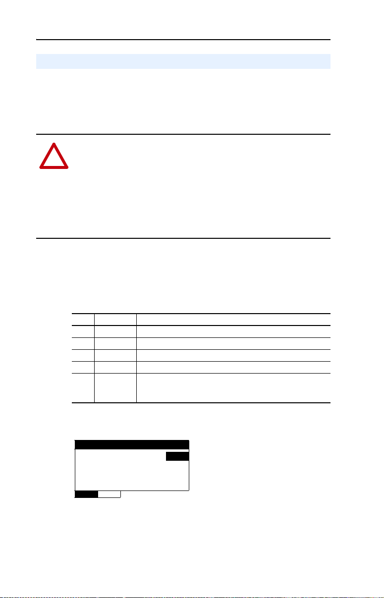
Step Example Screens
1. Power up the drive. Then plug the
2. Press key once to display the
3. Press (Enter) key to display
. For additional HIM information, refer to the Pow erFl ex
external HIM into the bottom of the
drive. The Parameters menu for
the drive
will be displayed.
Sel
Device Select menu.
the DSI Devices menu. Press
Arrow to scroll to
22-COMM-B.
for styles. Basic steps to access
Parameters
Groups
Linear List
Changed Params
DIAG PAR A M DSEL MEM SEL
Device Select
DSI Devices
DIAG PARAM DSEL MEM SEL
DSI Devices
PowerFlex 4 0
22-COMM-B
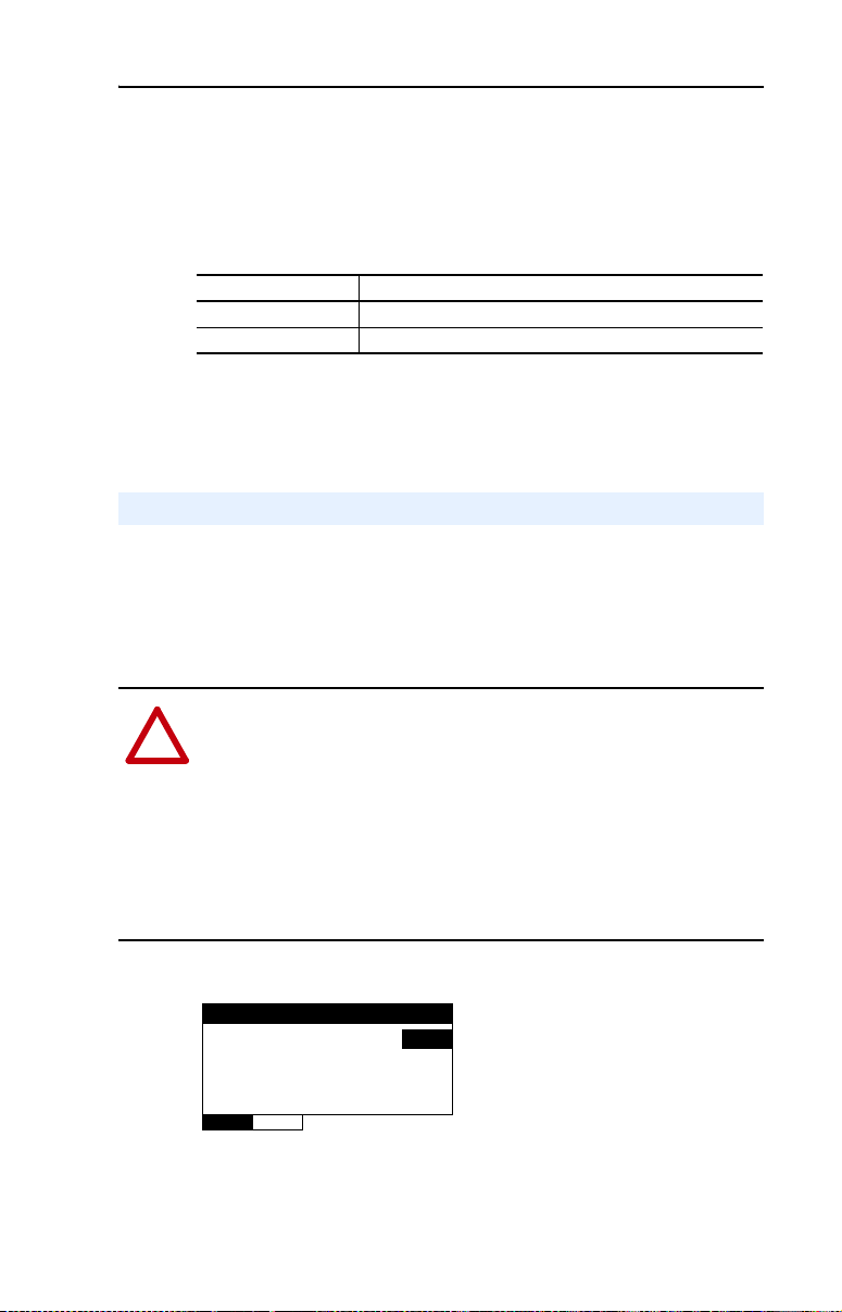
4. Press (Enter) key to select
the adapter. The Parameters menu
for the adapter
5. Press (Enter) key to access
the parameters. Edit the adapter
parameters using the same
techniques that you use to edit
drive parameters.
will be displayed.
Parameters
Linear List
Changed Params
DIAG PA R A M DSEL MEM SEL
Reset Module
Parameter : #
Ready 0
VAL UE LIMITS SEL
001
Page 31

Configuring the Adapter 3-3
NOTE: All configuration procedures throughout this chapter use the
optional, external PowerFlex 4-Class HIM to access parameters in the
adapter and show example HIM screens.
Figure 3.1 Optional, External PowerFlex 4-Class HIMs
F Stopped Auto
Hz
A
V
LANGDISP
EscEsc
SelSel
9
8
7
6
5
4
1
3
2
+/-
0
.
DSI
REMOVE
ALT
Jog
F Stopped Auto
Hz
A
V
View Lang Remove
Esc
Sel
7 8 9
4 5 6
1 2 3
.
Alt
0 +/-
Param #
DISP
DSI
Jog
LANG
Esc
Sel
ALT
Jog
|
DSI
22-HIM-A3 Series A 22-HIM-A3 Series C 22-HIM-C2S
Series A or Series C
Page 32
3-4 Configuring the Adapter
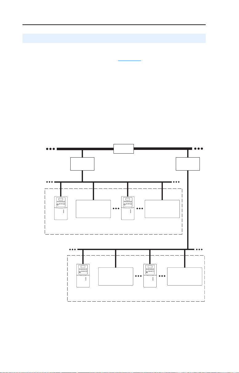
Setting the Device Instance Number
While there are many ways to implement Device Instance and network
strategies, the example shown in Figure 3.2
approach.
In this example, two individual Floor Level Networks are connected to
the Building Level Network through a router which allows devices on
each network to share the same MAC address. However, each device on
the network must have a unique Device Instance which, in this case,
consists of 4 digits. The first digit (in bold) represents the Building or
Floor number. The last 3 digits represent the device’s set MAC address.
Figure 3.2 Building Automation Network Example
illustrates one logical
Building Level Network 1
Router
Building
Controller 1
Building Level Network 2
Building
Controller 2
Floor Level Network 1 (BACnet MS/TP)
Bldg 1/Flr 1
Other Brand
Building Automation
Product
MAC Address 1
Device Instance 1001
The Device Instance Number can be a number from 1 to 4,194,302.
When the Device Instance Number is three digits or less, set Parameter
11 - [Device Inst Hi] to “0” (zero) and use Parameter 12 - [Device Inst
Lo] to directly enter the number. When the Device Instance Number is
four or more digits, use Parameter 11 - [Device Inst Hi] to enter the
MAC Address 2
Device Instance 1002
Bldg 2/Flr 2
MAC Address 1
Device Instance 2001
MAC Address 50
Device Instance 1050
Floor Level Network 2 (BACnet MS/TP)
Other Brand
Building Automation
Product
MAC Address 2
Device Instance 2002
Other Brand
Building Automation
Product
MAC Address 127
Device Instance 1127
MAC Address 50
Device Instance 2050
Other Brand
Building Automation
Product
MAC Address 127
Device Instance 2127
Page 33
Configuring the Adapter 3-5
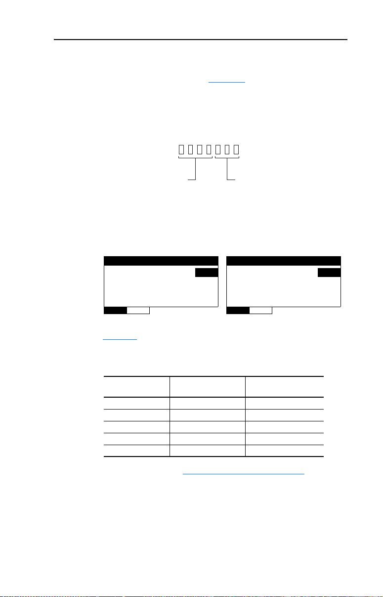
high portion (most significant digits) of the number and Parameter 12 [Device Inst Lo] to enter the low portion (always the three least
significant digits) of the number. Figure 3.3
the Device Instance Number for entry into the adapter.
Figure 3.3 Apportioning the Device Instance Number for Entry
Device Instance Number
illustrates how to apportion
Use Parameter 11 - [Device Inst Hi]
1. Enter the Device Instance Number using Parameter 11 - [Device
Most Significant Digits
to enter value.
Inst Hi] and Parameter 12 - [Device Inst Lo].
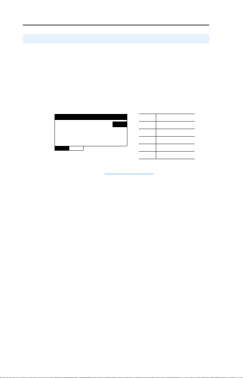
Figure 3.4 Example Device Inst Hi/Lo HIM Screens
Device Inst Hi
Parameter: #
160
VAL UE LIMITS SEL
Table 3.B shows Device Instance Number examples to illustrate the
values needed to be entered for each parameter.
Table 3.B Examples of Device Instance Numbers
Device Instance
Number
14 0 14
328 0 328
2369 2 369
160000 (default) 160 0
4150732 4150 732
Parameter 11 [Device Inst Hi] Value
011
Least Significant Digits
Use Parameter 12 - [Device Inst Lo]
to enter value.
Device Inst Lo
Parameter: #
0
VAL UE LIMITS SEL
Parameter 12 [Device Inst Lo] Value
012
2. Reset the adapter (see Resetting the Adapter on page 3-9) to apply
the new Device Instance Number.
Page 34
3-6 Configuring the Adapter
Setting a Comm Loss Action
By default, when communications are disrupted (for example, a cable is
disconnected), the drive responds by faulting if it is using I/O from the
network. You can configure a different response to communication
disruptions using Parameter 02 - [Comm Loss Action].
ATTENTION: Risk of injury or equipment damage exists.
Parameter 02 - [Comm Loss Action] lets you determine the action of
!
the adapter and connected drive if communications are disrupted. By
default, this parameter faults the drive. You can set this parameter so
that the drive continues to run. Take precautions to ensure that the
setting of this parameter does not create a risk of injury or equipment
damage. When commissioning the drive, verify that your system
responds correctly to various situations (for example, a disconnected
cable).
Changing the Comm Loss Action
Set the value of Parameter 02 - [Comm Loss Action] to the desired
response action:
Value Action Description
0 Fault The drive is faulted and stopped. (Default)
1 Stop The drive is stopped, but not faulted.
2 Zero Data The drive is sent 0 for output data. This does not command a stop.
3 Hold Last The drive continues in its present state.
4 Send Flt Cfg The drive is sent the data that you set in the fault configuration
Figure 3.5 Example Comm Loss Action HIM Screen
Comm Loss Action
Parameter: #
VAL UE LIMITS SEL
Changes to this parameter takes effect immediately. A reset is not
required.
parameters (Parameter 04 - [Flt Cfg Logic] and Parameter 05 [Flt Cfg Ref]).
002
Fault 0
Page 35
Configuring the Adapter 3-7
Setting the Fault Configuration Parameters
If you set Parameter 02 - [Comm Loss Action] to “Send Flt Cfg,” the
values in the following parameters are sent to the drive after a
communications fault occurs. You must set these parameters to values
required by your application.
Parameter Description
04 - [Flt Cfg Logic] A 16-bit value sent to the drive for Logic Command.
05 - [Flt Cfg Ref] A 16-bit value (0…65535) sent to the drive as a Reference.
Changes to these parameters take effect immediately. A reset is not
required.
Setting the Comm Loss Time
Set Parameter 03 - [Comm Loss Time] to a communication loss
timeout period suitable for your application. By default, the timeout is
set to ten (10) seconds. You can increase or decrease this value.
Alternatively, you can set the value to zero (0) to disable this timeout
feature so that the adapter does not detect communication losses.
ATTENTION: Risk of injury or equipment damage exists. Parameter
03 - [Comm Loss Time] lets you determine how long it will take the
!
adapter to detect network communication losses. By default, this
parameter sets the timeout to ten (10) seconds. You can set it so that the
duration is shorter, longer, or disabled. When set to disabled, this also
disables adapter Parameter 02 - [Comm Loss Action]. Therefore, a
communications fault action will be ignored. Take precautions to ensure
that the setting does not create a risk of injury or equipment damage.
When commissioning the drive, verify that your system responds
correctly to various situations (for example, a disconnected cable).
Figure 3.6 Example Comm Loss Time HIM Screen
Comm Loss Time
Parameter : #
10 sec
VAL UE LIMITS SEL
Changes to this parameter take effect immediately. A reset is not
required.
003
Page 36
3-8 Configuring the Adapter
Setting the Baud Rate
The value of Parameter 06 - [Baud Rate Cfg] determines the baud rate
used by the adapter. The Autobaud setting will detect the baud rate used
on the network if another device is setting the baud rate. Your application
may require a different setting.
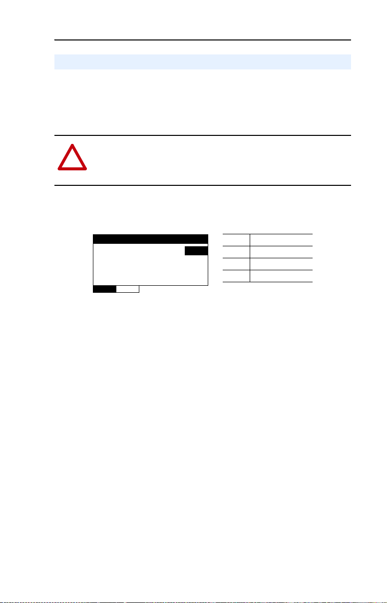
1. Set the value of Parameter 06 - [Baud Rate Cfg] to the baud rate at
which your network is operating.
Figure 3.7 Example Baud Rate Cfg HIM Screen
Baud Rate Cfg
Parameter: #
Autobaud 0
VAL UE LIMITS SEL
2. Reset the adapter (see Resetting the Adapter) so that the new baud
rate takes effect.
006
Value Description
0 Autobaud (Default)
1 9600
2 19200
3 38400
4 76800
Page 37
Configuring the Adapter 3-9
Resetting the Adapter
Changes to switch settings and some adapter parameters require that you
reset the adapter before the new settings take effect. You can reset the
adapter by cycling power to the drive or by using Parameter 01 - [Reset
Module].
ATTENTION: Risk of injury or equipment damage exists. If the
adapter is transmitting control I/O to the drive, the drive may fault
!
when you reset the adapter. Determine how your drive will respond
before resetting a connected adapter.
Set Parameter 01 - [Reset Module] to “1” (Reset Module).
Figure 3.8 Example Reset Module HIM Screen
Reset Module
Parameter : #
Reset Module 0
VAL UE LIMITS SEL
When you enter “1” (Reset Module), the adapter will be immediately
reset. When you enter “2” (Set Defaults), the adapter will set all adapter
parameters to their factory-default values. After performing a Set
Defaults, enter “1” (Reset Module) so that the new values take effect.
The value of this parameter will be restored to “0” (Ready) after the
adapter is reset.
Value Description
001
0 Ready (Default)
1 Reset Module
2 Set Defaults
Page 38

3-10 Configuring the Adapter
Viewing the Adapter Status Using Parameters
The following parameters provide information about the status of the
adapter. You can view these parameters at any time.
Parameter Description
07 - [Baud Rate Act] The baud rate used by the adapter. This will be one of the
08 - [MAC Address] The MAC address used by the adapter that was set by the MAC
Flash Updating the Adapter
The adapter can be flash updated over the network or serially through a
direct connection from a computer to the drive using a 1203-USB
converter or 22-SCM-232 serial converter module (firmware version
2.005 or later).
following values:
• The value of Parameter 06 - [Baud Rate Cfg].
• An old baud rate if Parameter 06 - [Baud Rate Cfg] has
been changed and the adapter has not been reset.
• The value “0” (Unknown) if Parameter 06 - [Baud Rate Cfg]
is set to “0” (Autobaud) and the adapter has not yet detected
the baud rate.
Address Switches SW1…SW7 (Figure 2.1
).
When flashing over the network, you can use the Allen-Bradley software
tool ControlFLASH, the built-in flash capability of DriveExplorer Lite
or Full, or the built-in flash capability of DriveExecutive.
When flashing through a direct serial connection from a computer to a
drive, you can use the same Allen-Bradley software tools described
above, or you can use HyperTerminal set to the X-modem protocol.
To obtain a flash update for this adapter, go to http://www.ab.com/
support/abdrives/webupdate. This site contains all firmware update files
and associated Release Notes that describe firmware update
enhancements/anomalies, how to determine the existing firmware
version, and how to flash update using DriveExplorer, DriveExecutive,
ControlFLASH or HyperTerminal.
Page 39

Chapter 4
Using BACnet Objects
This chapter provides information about controlling a PowerFlex 4-Class
drive using BACnet objects.
Topic Page
Understanding BACnet Objects
Basic Drive Operation on the Network 4-2
Supported BACnet Objects 4-3
Understanding BACnet Objects
BACnet nodes are controlled and monitored by the use of several types
of objects. The BACnet controller performs read and write commands to
these objects, and the adapter transfers/translates the data between these
objects and the drive.
When a read or write command occurs to a specific object, data in the
object is refreshed from or transferred to the drive.
4-1
The BACnet object types that are supported by the adapter are:
• Analog Input (AI)
• Analog Output (AO)
• Analog Value (AV)
• Binary Input (BI)
• Binary Output (BO)
• Binary Value (BV)
Page 40

4-2 Using BACnet Objects
Basic Drive Operation on the Network
This section describes how to operate a drive on the network using a
combination of BACnet object types for basic control.
ATTENTION: Control information written to the adapter by a BACnet
controller is volatile. That is, it will not survive an adapter reset or
!
power cycle. For example, if a BACnet controller writes to a Binary
Output (BO) object to energize an output relay on the drive and then
that drive is reset or power cycled, the drive will return the relay to its
default (de-energized) state. The adapter will not attempt to restore the
relay to the energized state unless a BACnet controller writes to it again.
Basic Drive Control (Start/Stop)
1. Write a speed reference value (in %) to the Reference 1 Analog
Value object (AV0) Present Value property.
2. To start the drive, write a value of “1” to the Run/Stop Binary Value
object (BV10) Present Value property.
3. To stop the drive, write a value of “0” (zero) to the Run/Stop Binary
Value object (BV10) Present Value property.
Using an Alternate Speed Reference
To assign an alternate speed reference to the drive:
1. Write a speed reference value (in %) to the Reference 2 Analog
Value object (AV1) Present Value property.
2. Write a value of “1” to the Ref2/Ref1 Binary Value object (BV12)
Present Value property.
Changing Motor Rotation Direction
To command a reverse direction of motor rotation when the drive is
running, write a value of “1” to the Rev/Fwd Binary Value object
(BV11) Present Value property. To command a forward direction when
the drive is running, write a value of “0” (zero) to the Rev/Fwd Binary
Value object (BV11) Present Value property.
Clearing a Drive Fault
To clear a drive fault, write a value of “1” to the Clear Faults Binary Value
object (BV13) Present Value property.
Page 41

Using BACnet Objects 4-3
Supported BACnet Objects
The type of drive used on the network determines the specific BACnet
objects that are supported. Refer to Table 4.A
BACnet objects and the drives supporting those objects.
for descriptions of the
Compatible PowerFlex Drives
44M40400
✔✔✔✔
✔✔✔✔
Analog Input (AI) Objects
Analog Output (AO) Objects
terminal block.
terminal block.
——✔✔
(Powerflex 400) on the drive’s I/O terminal block. The drive must be configured
to accept the value of this output from the network. This is done by setting the
following drive parameter:
• PowerFlex 40: A065 - [Analog Out Sel] to the value “18” (Setpnt 0-10), “19”
(Setpnt 0-20) or “20” (Setpnt 4-20)
———✔
“12” (Setpnt 0-20) or “19” (Setpnt 4-20)
drive must be configured to accept the value of this output from the network.
• PowerFlex 400: T082 - [Analog Out1 Sel] to the value “5” (Setpnt 0-10),
This is done by setting drive parameter T085 - [Analog Out2 Sel] to the value
✔✔✔✔
Analog Value (AV) Objects
“5” (Setpnt 0-10), “12” (Setpnt 0-20) or “19” (Setpnt 4-20).
configured to accept its speed reference from the network. This is typically
done by setting drive parameter P038 - [Speed Reference] to the value “5”
(Comm Port).
Table 4.A BACnet Object Descriptions and Supported Drives
Object Name Use This Object to…
AI0 Analog Input 1 (%) Read the value of Analog Input 1 (voltage or current) on the drive’s I/O
AI1 Analog Input 2 (%) Read the value of Analog Input 2 (voltage or current) on the drive’s I/O
AO0 Analog Output 1 (%) Read/write the value of Analog Output (PowerFlex 40) or Analog Output 1
AO1 Analog Output 2 (%) Read/write the value of Analog Output 2 on the drive’s I/O terminal block. The
AV0 Reference 1 (%) Read/write the Reference 1 and Reference 2 values. The drive must be
AV1 Reference 2 (%) ✔✔✔✔
AV2 Output Frequency (Hz) Read the drive’s output frequency. ✔✔✔✔
Page 42

4-4 Using BACnet Objects
Compatible PowerFlex Drives
4 4M 40 400
———✔
Note: When writing, this object accepts only a value of “0” (zero).
✔✔✔✔
Note: When writing, this object accepts only a value of “0” (zero).
• PowerFlex 400: Read/write the drive’s accumulated run time.
✔✔✔✔
Binary Input (BI) Objects
for the desired parameter to the Mailbox Param object, and then read the
Mailbox Value object. To write a drive parameter, write the number for the
desired parameter to the Mailbox Param object, and then write the desired
value to the Mailbox Value object.
Object Name Use This Object to…
AV3 Output Current (Amps) Read the drive’s output current. ✔✔✔✔
AV4 Output Voltage (VAC) Read the drive’s output voltage. ✔✔✔✔
AV5 Output Power (kW) Read the drive’s output power. — — ✔✔
AV6 Output Energy (kWh) Read/write the drive’s accumulated output energy.
AV7 DC Bus Voltage (VDC) Read the drive’s DC bus voltage. ✔✔✔✔
AV8 Drive Temp (°C) Read the drive’s temperature. ✔✔✔✔
AV9Reserved — ————
AV10Reserved — ————
AV11 Run Time (Hours) • PowerFlex 4/4M/40: Read the drive’s accumulated run time.
AV12 Fault 1 Read the code for the drive’s most recent fault. ✔✔✔✔
AV13 Fault 2 Read the code for the drive’s second most recent fault. ✔✔✔✔
AV14 Fault 3 Read the code for the drive’s third most recent fault. ✔✔✔✔
AV15 Accel Time 1 (Sec) Read/write the drive’s Accel Time 1 setting. ✔✔✔✔
AV16 Decel Time 1 (Sec) Read/write the drive’s Decel Time 1 setting. ✔✔✔✔
AV17 Mailbox Param Read/write any drive parameter. To read a drive parameter, write the number
Table 4.A BACnet Object Descriptions and Supported Drives (Continued)
AV18 Mailbox Value ✔✔✔✔
BI0 Stop Input Read the state of the Stop Input on the drive’s I/O terminal block. ✔✔✔✔
Page 43

Using BACnet Objects 4-5
Compatible PowerFlex Drives
4 4M 40 400
• PowerFlex 4/40: P055 - [Relay Out Sel] to the value “20” (ParamControl)
• PowerFlex 4M: t221 - [Relay Out Sel] to the value “11” (ParamControl)
——✔✔
• PowerFlex 400: T055 - [Relay Out1 Sel] to the value “12” (ParamControl)
drive must be configured to accept the value of this output from the network.
✔✔✔✔
Binary Output (BO) Objects
drive must be configured to accept the value of this output from the network.
This is done by setting the following drive parameter:
This is done by setting the following drive parameter:
• PowerFlex 40: P058 - [Opto Out1 Sel] to the value “20” (ParamControl)
——✔✔
• PowerFlex 400: T060 - [Relay Out2 Sel] to the value “12” (ParamControl)
drive must be configured to accept the value of this output from the network.
This is done by setting the following drive parameter:
• PowerFlex 40: P061 - [Opto Out2 Sel] to the value “20” (ParamControl)
• PowerFlex 400: T065 - [Opto Out Sel] to the value “12” (ParamControl)
Object Name Use This Object to…
BI1 Start Input Read the state of the Start Input on the drive’s I/O terminal block. ✔✔✔✔
BI2 Dir Input Read the state of the Dir (Direction) Input on the drive’s I/O terminal block. ✔✔✔✔
BI3 Digital Input 1 Read the state of Digital Input 1 on the drive’s I/O terminal block. ✔✔✔✔
BI4 Digital Input 2 Read the state of Digital Input 2 on the drive’s I/O terminal block. ✔✔✔✔
Table 4.A BACnet Object Descriptions and Supported Drives (Continued)
BI5 Digital Input 3 Read the state of Digital Input 3 on the drive’s I/O terminal block. — — ✔✔
BO0 Digital Output Cmd 1 Read/write the state of Digital Output 1 on the drive’s I/O terminal block. The
BI6 Digital Input 4 Read the state of Digital Input 4 on the drive’s I/O terminal block. — — ✔✔
BO1 Digital Output Cmd 2 Read/write the state of Digital Output 2 on the drive’s I/O terminal block. The
BO2 Digital Output Cmd 3 Read/write the state of Digital Output 3 on the drive’s I/O terminal block. The
Page 44

4-6 Using BACnet Objects
4 4M 40 400
Compatible PowerFlex Drives
✔✔✔✔
✔✔✔✔
✔✔✔✔
✔✔✔✔
✔✔✔✔
✔✔✔✔
✔✔✔✔
Binary Value (BV) Objects
Object Name Use This Object to…
Table 4.A BACnet Object Descriptions and Supported Drives (Continued)
run command.
BV0 Ready Read the drive’s Ready status, which is active if the drive is ready to accept a
in the reverse direction.
BV1 Running Read the drive’s Running status, which is active if the drive is running. ✔✔✔✔
BV2 Running Reverse Read the drive’s Running Reverse status, which is active if the drive is running
the specified speed reference.
drive. Turn off this object to stop the drive.
BV3 Fault Read the drive’s Fault status, which is active if the drive is faulted. ✔✔✔✔
BV4 Alarm Read the drive’s Alarm status, which is active if the drive has an alarm. ✔✔✔✔
BV5 At Reference Read the drive’s At Reference status, which is active if the drive is running at
BV10 Run/Stop Read/write the adapter’s Run/Stop command. Turn on this object to start the
the reverse direction when the drive is running. Turn off this object to
BV11 Rev/Fwd Read/write the adapter’s Rev/Fwd command. Turn on this object to command
command Forward.
Reference 2 instance of the AV object as the drive’s speed reference. Turn off
this object to select Reference 1. The drive must be configured to accept its
speed reference from the network. This is typically done by setting drive
parameter P038 - [Speed Reference] to the value “5” (Comm Port).
the drive fault. Turning off this object does nothing.
BV12 Ref2/Ref1 Read/write the adapter’s Ref2/Ref1 command. Turn on this object to select the
BV13 Clear Faults Read/write the adapter’s Clear Faults command. Turn on this object to clear
Page 45

Chapter 5
Troubleshooting
This chapter provides information for diagnosing and troubleshooting
potential problems with the adapter and network.
Topic Page
Understanding the Status Indicators
PORT Status Indicator 5-2
MOD Status Indicator 5-2
NET A Status Indicator 5-3
NET B Status Indicator 5-3
Viewing Adapter Diagnostic Items 5-4
Viewing and Clearing Events 5-5
5-1
Understanding the Status Indicators
The adapter has four status indicators. They can be viewed on the
adapter or through the drive cover. See Figure 5.1
.
Figure 5.1 Status Indicators (location on drive may vary)
➊
➋
➌
➍
Bottom side
of adapter board
Item Status Indicator Description Page
PORT DSI Connection Status 5-2
➊
MOD Adapter Status 5-2
➋
NET A Serial Communication Status 5-3
➌
NET B Serial Communication Traffic Status 5-3
➍
➊
➋
➌
➍
Page 46

5-2 Troubleshooting
PORT Status Indicator
State Cause Corrective Actions
Off The adapter is not powered or
Flashing
Red
Orange The adapter is connected to a
Flashing
Green
Steady
Green
is not properly connected to
the drive.
The adapter is not receiving
communication from the drive.
drive that is not compatible.
The adapter is establishing
communications with the
drive.
The adapter is properly
connected and is
communicating with the drive.
• Securely connect the adapter to the drive
using the Internal Interface (ribbon)
cable.
• Apply power to the drive (or adapter if
mounted in a DSI External Comms Kit).
• Verify that cables are securely connected
and not damaged. Replace cables if
necessary.
• Cycle power to the drive (or adapter if
mounted in a DSI External Comms Kit).
Connect the adapter to a compatible
PowerFlex 4, PowerFlex 4M, PowerFlex 40
or PowerFlex 400 drive.
No action required. This status indicator will
turn steady green or flashing red.
No action required.
MOD Status Indicator
State Cause Corrective Actions
Off The adapter is not powered or
Flashing
Red
Flashing
Green
Steady
Green
is not properly connected to
the drive.
The adapter has failed the
firmware test.
The adapter is operational, but
is not transferring I/O data.
The adapter is operational and
transferring I/O data.
• Securely connect the adapter to the drive
using the Internal Interface (ribbon)
cable.
• Apply power to the drive (or adapter if
mounted in a DSI External Comms Kit).
• Cycle power to the drive (or adapter if
mounted in a DSI External Comms Kit).
• If cycling power does not correct the
problem, the adapter parameter settings
may have been corrupted. Reset defaults
and reconfigure the adapter.
• If resetting defaults does not correct the
problem, flash the adapter with the latest
firmware release.
Enable the network device that is providing
control to the adapter.
No action required.
Page 47

Troubleshooting 5-3
NET A Status Indicator
State Cause Corrective Actions
Off The adapter is not powered or
Flashing
Red
Flashing
Green
is not properly connected to
the network.
A network connection has
timed out.
The adapter is properly
connected and communicating
on the network.
• Securely connect the adapter to the drive
using the Internal Interface (ribbon)
cable.
• Correctly connect the network cable to
the adapter’s network connector.
• Apply power to the drive (or adapter if
mounted in a DSI External Comms Kit)
and network.
• Enable the network device that is
providing control to the adapter.
• Check the amount of traffic on the
network.
No action required. The LED will flash
green each time the token is passed to the
adapter by another BACnet device.
NET B Status Indicator
State Cause Corrective Actions
Off Adapter is not powered or is
not transmitting on the
network.
Flashing
Green
The adapter is transmitting on
the network.
If NET A indicator is off:
• Securely connect the adapter to the drive
using the Internal Interface (ribbon)
cable, and to the network using the
appropriate network cable.
• Correctly connect the network cable to
the adapter’s network connector.
Normal condition if the adapter is idle.
No action required.
Page 48

5-4 Troubleshooting
Viewing Adapter Diagnostic Items
If you encounter unexpected communications problems, the adapter’s
diagnostic items can help you or Rockwell Automation personnel
troubleshoot the problem. Adapter diagnostic items can be viewed using
a PowerFlex 4-Class HIM, DriveExplorer software (version 3.01 or
later), or DriveExecutive software (version 3.01 or later).
Table 5.A Adapter Diagnostic Items
No. Name Description
1Reserved —
2 Logic Cmd The present value of the Logic Command being transmitted to
3 Reference The present value of the Reference being transmitted to the
4Reserved —
5 Logic Sts The present value of the Logic Status being received from the
6 Feedback The present value of the Feedback being received from the
7 DSI Overrun Errs The number of DSI receive overrun errors.
8 DSI Framing Errs The number of DSI receive framing errors.
9 DSI CRC Errs The number of DSI receive CRC errors.
10 Boot Flash Count The number of times the boot firmware in this adapter has
11 App Flash Count The number of times the application firmware in this adapter
12 MAC Addr SW The MAC address selected by the DIP switches (SW1…SW7)
13 BN Rx Packets The number of BACnet packets received by the adapter.
14 BN Tx Packets The number of BACnet packets transmitted by the adapter.
15 BN Overrun Errs A count of the number of BACnet receive overrun errors.
16 BN Framing Errs A count of the number of BACnet receive framing errors.
17 BN CRC Errs A count of the number of BACnet receive CRC errors.
the drive by the adapter.
drive by the adapter.
drive by the adapter.
drive by the adapter.
been flash updated.
has been flash updated.
on the adapter. This value is not latched when the adapter
powers up, and will update as the switch settings are
changed.
Page 49
Troubleshooting 5-5
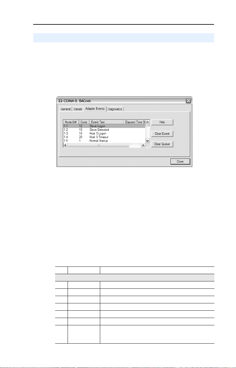
Viewing and Clearing Events
The adapter has an event queue to record significant events that occur in
the operation of the adapter. When such an event occurs, an entry is put
into the event queue. You can view the event queue using a PowerFlex
4-Class HIM, DriveExplorer software (version 3.01 or later), or
DriveExecutive software (version 3.01 or later).
Figure 5.2 DriveExplorer Event View/Clear Screen
The event queue can contain up to 32 entries. Eventually the event queue
will become full, since its contents are retained through adapter resets.
At that point, a new entry replaces the oldest entry. Only an event queue
clear operation or adapter power cycle will clear the event queue
contents.
Resetting the adapter to defaults has no effect on the event queue.
Many events in the event queue occur under normal operation. If you
encounter unexpected communications problems, the events may help
you or Allen-Bradley personnel troubleshoot the problem. The following
events may appear in the event queue.
Table 5.B Adapter Events
Code Event Description
Adapter Events
0 No Event Text displayed in an empty event queue entry.
1 Normal Startup Power is applied to the adapter.
2 Manual Reset The adapter was reset from the “Reset Module” parameter.
3 Watchdog T/O Flt The software watchdog detected a failure and reset the adapter.
4 App Updated The application firmware has been flash updated.
5 Boot Updated The boot firmware has been flash updated.
6 EEPROM Sum
Flt
The EEPROM checksum/CRC is incorrect. The functionality of
the adapter will be limited. Default parameter values must be
loaded to clear this condition.
Page 50

5-6 Troubleshooting
Code Event Description
7–9 Reserved —
10 Slave Detected The adapter detected that the slave has been connected.
11 Slave Removed The adapter detected that the slave has been disconnected.
12 Slave Logon The adapter has established communications with the slave.
13 Slave Timeout The adapter has lost communications with the slave.
14 Slave Brand Flt The slave brand is different than the adapter.
15 Host 0 Logon The adapter has established communications with the drive.
16-19 Reserved —
20 Host 0 Timeout The adapter has lost communications with the drive.
21-24 Reserved —
25 Host 0 Brand Flt The drive is not an Allen-Bradley brand drive.
26–39 Reser ved —
40 Net Link Up The network link is established.
41 Net Link Down The network link is lost.
42 Dup Net Addr The adapter detected that another device is using its network
43 Net Open An I/O connection from the network to the adapter was opened.
44 Net Close An I/O connection from the network to the adapter was closed.
45 Net Timeout An I/O connection from the network to the adapter has timed
46 Net Comm Flt The adapter has performed the “Comm Flt” action specified by
47 Net Idle Flt The adapter has performed the “Idle Flt” action specified by the
48 PCCC IO Open The adapter has begun receiving PCCC Control messages (the
49 PCCC IO Close The device sending PCCC Control messages to the adapter
50 PCCC IO Time
Flt
51 Net Sent Reset The adapter received a reset from the network.
52 Msg Ctrl Open The adapter has begun receiving Client-Server Control
53 Msg Ctrl Close The device sending Client-Server Control messages to the
54 Msg Ctrl
Timeout
DSI Events
Network Events
address. In this case, the adapter will not participate in any
network activity.
out.
the user.
user.
PCCC Control Timeout was previously set to a non-zero value).
has set the PCCC Control Timeout to a value of zero.
The adapter has not received a PCCC Control message for
longer than the PCCC Control Timeout.
messages (the Client-Server Control Timeout was previously
set to a non-zero value).
adapter has set the Client-Server Control Timeout to a value of
zero.
The adapter has not received a Client-Server Control message
for longer than the established timeout period.
Page 51

Appendix A
Specifications
Appendix A presents the specifications for the adapter.
Topic Page
Communications
Electrical A-1
Mechanical A-1
Environmental A-2
Regulatory Compliance A-2
Communications
A-1
Network
Protocol
Data Rates
Drive
Protocol
Data Rate
BACnet MS/TP
9600, 19200, 38400 or 76800 baud
DSI
19.2 kbps
Electrical
Consumption
Drive
Network
Mechanical
Dimensions
Height
Length
Width
Weight 85g (3 oz.)
275 mA at 5 VDC supplied by the host (drive or DSI
External Comms Kit)
None
19 mm (0.75 inches)
86 mm (3.39 inches)
78.5 mm (3.09 inches)
Page 52

A-2 Specifications
Environmental
Temperature
Operating
Storage
Relative Humidity 5…95% non-condensing
Atmosphere Important: Adapter must not be installed in an area
Regulatory Compliance
Certification Specification
BACnet BTL (BACnet Testing Laboratories) approval pending
UL UL508C
cUL CAN / CSA C22.2 No. 14-M91
CE EN50178 and EN61800-3
CTick EN61800-3
-10…50 °C (14…122 °F)
-40…85 °C (-40…185 °F)
where the ambient atmosphere contains volatile or
corrosive gas, vapors or dust. If the adapter is not going
to be installed for a period of time, it must be stored in an
area where it will not be exposed to a corrosive
atmosphere.
NOTE: The addition of a ferrite core (Fair-Rite P/N 0431167281 or
equivalent) to the BACnet cable might be required on applications which
must meet IEC 61800-3.
NOTE: This is a product of category C2 according to IEC 61800-3. In a
domestic environment this product may cause radio interference in
which case supplementary mitigation measures may be required.
Page 53
Appendix B
Adapter Parameters
Appendix B provides information about the adapter parameters.
Topic Page
About Parameter Numbers
Parameter List B-1
About Parameter Numbers
The parameters in the adapter are numbered consecutively. However,
depending on which configuration tool you use, they may have different
numbers.
Configuration Tool Numbering Scheme
• DriveExplorer
• DriveExecutive
• HIM
B-1
The adapter parameters begin with parameter 1. For
example, Parameter 01 - [Reset Module] is parameter 1 as
indicated by this manual.
Parameter List
Parameter
No. Name and Description Details
01 [Reset Module]
No action if set to “0” (Ready). Resets the adapter
if set to “1” (Reset Module). Restores the adapter
to its factory default settings if set to “2” (Set
Defaults). This parameter is a command. It will be
reset to “0” (Ready) after the command has been
performed.
ATTENTION: Risk of injury or equipment damage exists. If the adapter is
transmitting I/O that controls the drive, the drive may fault when you reset the
adapter. Determine how your drive will respond before resetting a connected
!
adapter.
Default: 0 = Ready
Values 0 = Ready
Type: Read/Write
Reset Required: No
1 = Reset Module
2 = Set Defaults
Page 54

B-2 Adapter Parameters
Parameter
No. Name and Description Details
02 [Comm Loss Action]
Sets the action that the adapter and drive will take
if the adapter detects that network
communications have been disrupted. This setting
is effective only if I/O that controls the drive is
transmitted through the adapter.
ATTENTION: Risk of injury or equipment damage exists. Parameter 02 - [Comm
Loss Action] lets you determine the action of the adapter and connected drive if
communications are disrupted. By default, this parameter faults the drive. You
!
can set this parameter so that the drive continues to run. Precautions should be
taken to ensure that the setting of this parameter does not create a risk of injury
or equipment damage. When commissioning the drive, verify that your system
responds correctly to various situations (for example, a disconnected drive).
Default: 0 = Fault
Values: 0 = Fault
Type: Read/Write
Reset Required: No
1 = Stop
2 = Zero Data
3 = Hold Last
4 = Send Flt Cfg
03 [Comm Loss Time]
Sets the communication loss timeout period in
seconds. The value zero disables this feature.
ATTENTION: Risk of injury or equipment damage exists. Parameter 03 - [Comm
Loss Time] lets you determine how long it will take the adapter to detect network
communication losses. By default, this parameter sets the timeout to ten (10)
!
seconds. You can set it so that the duration is shorter, longer, or disabled. When
set to disabled, this also disables adapter Parameter 02 - [Comm Loss Action].
Therefore, a communications fault action will be ignored. Take precautions to
ensure that the setting does not create a risk of injury or equipment damage.
When commissioning the drive, verify that your system responds correctly to
various situations (for example, a disconnected cable).
04 [Flt Cfg Logic]
Sets the Logic Command data that is sent to the
drive if Parameter 02 - [Comm Loss Action] is
set to “Send Flt Cfg” and network communications
are disrupted.
The bit definitions will depend on the product to
which the adapter is connected. See the
documentation for the drive being used.
05 [Flt Cfg Ref]
Sets the Reference data that is sent to the drive if
Parameter 02 - [Comm Loss Action] is set to
“Send Flt Cfg” and communications are disrupted.
Default: 10 seconds
Minimum: 0 seconds
Maximum: 180 seconds
Type: Read/Write
Reset Required: No
Default: 0000 0000 0000 0000
Minimum: 0000 0000 0000 0000
Maximum: 1111 1111 1111 1111
Type: Read/Write
Reset Required: No
Default: 0
Minimum: 0
Maximum: 65535
Type: Read/Write
Reset Required: No
Page 55

Parameter
No. Name and Description Details
06 [Baud Rate Cfg]
Sets the baud rate (kilobits per second) at which
the adapter communicates. (Updates Parameter
07 - [Baud Rate Act] after a reset.)
07 [Baud Rate Act]
Displays the baud rate (kilobits per second)
actually used by the adapter.
08 [MAC Address]
Displays the address set by the MAC Address
Switches SW1…SW7 (Figure 2.1
This value is latched when the adapter powers up.
09 [Max Master]
Sets the maximum MAC Address for any device in
the BACnet MS/TP token ring.
10 [Max Info Frames]
Sets the maximum number of messages that the
adapter can transmit while it owns the token.
11 [Device Inst Hi]
Sets the high portion (most significant digits) of
the Device Instance Number. The Device Instance
Number used by the adapter is the value of this
parameter times 1000 plus the value of Parameter
12 - [Device Inst Lo].
12 [Device Inst Lo]
Sets the low portion (always the last three least
significant digits) of the Device Instance Number.
The Device Instance Number used by the adapter
is the value of Parameter 11 - [Device Inst Hi]
times 1000 plus the value of this parameter.
) on the adapter.
Default: 0 = Autobaud
Values: 0 = Autobaud
Type: Read/Write
Reset Required: Yes
Default: 0 = Unknown
Values: 0 = Unknown
Type: Read Only
Default: 0
Minimum: 0
Maximum: 127
Type: Read Only
Default: 127
Minimum: 0
Maximum: 127
Type: Read/Write
Reset Required: Yes
Default: 1
Minimum: 1
Maximum: 255
Type: Read/Write
Reset Required: Yes
Default: 160
Minimum: 0
Maximum: 4194
Type: Read/Write
Reset Required: Yes
Default: 0
Minimum: 0
Maximum: 999
Type: Read/Write
Reset Required: Yes
Adapter Parameters B-3
1 = 9600 kbps
2 = 19200 kbps
3 = 38400 kbps
4 = 76800 kbps
1 = 9600 kbps
2 = 19200 kbps
3 = 38400 kbps
4 = 76800 kbps
Page 56

B-4 Adapter Parameters
Notes:
Page 57

Appendix C
Protocol Implementation Conformance Statement (PICS)
Date: March 27, 2006
Vendor Name: Rockwell Automation
Product Name: 22-COMM-B
Product Model Number: 22-COMM-B
Applications Software Version: 3.003
Firmware Revision: 1.001
BACnet Protocol Revision: 2
Product Description
DSI to BACnet MS/TP communication adapter for PowerFlex 4-Class
drives
BACnet Standardized Device Profile (Annex L)
BACnet Operator Workstation (B-OWS)
BACnet Building Controller (B-BC)
BACnet Advanced Application Controller (B-AAC)
BACnet Application Specific Controller (B-ASC)
BACnet Smart Sensor (B-SS)
BACnet Smart Actuator (B-SA)
List all BACnet Interoperability Building Blocks Supported (Annex K)
DS-RP-B, DS-RPM-B,
DS-WP-B, DS-WPM-B,
DM-DDB-B, DM-DOB-B,
DM-DCC-B,
DM-PT-A, DM-PT-B,
DM-RD-B
Segmentation Capability
Segmented requests supported Window size ________
Segmented responses supported Window size ________
Page 58

C-2 Protocol Implementation Conformance Statement (PICS)
Standard Object Types Supported
The table below lists the object types supported by the 22-COMM-B.
Dynamic object creation and deletion is not supported. The property
access rules use the following key:
R = Read Only: the property is supported for this object type
W = Read/Write: the property is supported for this object type
C = Commandable: the property is supported for this object type
Analog
Analog
Analog
Binary
Binary
Property
APDU Timeout R
Application Software Version R
Database Revision R
Description RRRRRRW
Device Address Binding R
Event State RRRRRR
Firmware Revision R
Location W
Max APDU Length Accepted R
Max Info Frames W
Max Master W
Model Name R
Number of APDU Retries R
Object Identifier R R R RRRR
Object List R
Object Name RRRRRRR
Object Type RRRRRRR
Out of Service RRRRRR
Polari ty R R
Present Value R C C
Priority Array R R
Protocol Object Types Supported R
Protocol Revision R
Protocol Services Supported R
Protocol Version R
Relinquish Default R R
Segmentation Supported R
Status Flags R R R R R R
System Status R
Units RRR
Vendor Identifier R
Vendor Name R
(1)
This property will accept a maximum of 16 characters when written.
(2)
This property will accept a maximum of 32 characters when written.
(3)
This property will accept a value between 1 and 255 inclusive when written.
(4)
This property will accept a value between 0 and 127 inclusive when written.
(5)
This property is commandable for some instances of this object. Otherwise it is read/write.
(6)
This property is supported only for instances of this object where the Present Value property is commandable.
Input
Output
Value
(5)
(6)
(6)
Input
RCC
Binary
Output
Value
RR
RR
Device
(1)
(2)
(3)
(4)
(5)
(6)
(6)
Page 59

Protocol Implementation Conformance Statement (PICS) C-3
Data Link Layer Options
BACnet IP, (Annex J)
BACnet IP, (Annex J), Foreign Device
ISO 8802-3, Ethernet (Clause 7)
ANSI/ATA 878.1, 2.5 Mb. ARCNET (Clause 8)
ANSI/ATA 878.1, RS-485 ARCNET (Clause 8), baud rate(s)
MS/TP master (Clause 9), baud rate(s): 9600, 19200, 38400, 76800
MS/TP slave (Clause 9), baud rate(s):
Point-To-Point, EIA 232 (Clause 10), baud rate(s):
Point-To-Point, modem (Clause 10), baud rate(s):
LonTalk, (Clause 11), medium:
Other:
Device Address Binding
Is static device binding supported? (This is currently necessary for
two-way communication with MS/TP slaves and certain other devices.)
Yes No
Networking Options
Not applicable.
Page 60

C-4 Protocol Implementation Conformance Statement (PICS)
Notes:
Page 61

Appendix D
Routing Capability for Networked Drives
Appendix D provides information about the unique routing capability for
up to 127 PowerFlex 4/4M/40/400 drives on a BACnet MS/TP network
when using the DriveExplorer (Full version only) drive software tool.
First, configure the 22-COMM-B adapter in each networked drive (or
DSI External Comms Kit) using the procedures described in Chapter 2
(NOTE: To be compatible with PowerFlex 4M drives, the 22-COMM-B
adapter must have firmware version 1.003 or later.) Then use a 1203-USB
or 22-SCM-232 converter to connect the first networked drive to a laptop
or desktop PC with DriveExplorer Full. Thereafter, you can use
DriveExplorer Full to route to any drive on the BACnet MS/TP network
to configure or monitor the drive or any of its connected peripherals.
Figure D.1 BACnet MS/TP Network Routing Capability
.
PowerFlex 4-Class Drives
Laptop or
Desktop PC
with DriveExplorer Full
1
PC Cable
1203-USB
Converter
Drive Cable
Use DriveExplorer Full to connect
to a single drive and configure
its installed BACnet adapter
1
PowerFlex 40 and PowerFlex 400 Drives (with internally-mounted 22-COMM-B adapters as shown) or
any PowerFlex 4-Class Drives (typically PowerFlex 4 and PowerFlex 4M) connected to 22-COMM-B
adapters that are mounted in DSI External Comms Kits.
Use DriveExplorer Full to route through DSI to drives
connected directly on BACnet (Up to 127 drives!)
BACnet MS/TP Network
Page 62

D-2 Routing Capability for Networked Drives
Notes:
Page 63

A Adapter
Devices such as drives, controllers, and computers usually require an
adapter to provide a communication interface between them and a
network such as BACnet MS/TP. An adapter reads data on the network
and transmits it to the connected device. It also reads data in the device
and transmits it to the network.
The 22-COMM-B adapter connects PowerFlex 4, PowerFlex 4M,
PowerFlex 40 or PowerFlex 400 drives to a BACnet MS/TP network.
(NOTE: The 22-COMM-B adapter must have firmware version 1.003 or
later to be compatible with PowerFlex 4M drives.) Adapters are
sometimes also called “cards,” “embedded communication options,”
“gateways,” “modules,” and “peripherals.”
B BACnet MS/TP
BACnet is a data communication protocol for B
Control networks. BACnet MS/TP (master-slave/token-passing) is a
specific type of BACnet network designed to run at speeds of 1 Mbps or
less over twisted pair wiring.
Baud Rate
The speed at which data is transferred on the network. Each device on a
network must be set for the same baud rate.
uilding Automation and
Glossary
C ControlFLASH
An Allen-Bradley software tool that lets users electronically update
firmware on printed circuit boards.
D DSI (Drive Serial Interface)
DSI is based on the Modbus RTU serial communication protocol and is
used by various Allen-Bradley drives and power products, such as
PowerFlex 4-Class drives.
DSI Peripheral
A device that provides an interface between DSI and a network or user.
Peripheral devices are also referred to as “adapters” or “modules.” The
22-COMM-B adapter, 1203-USB or 22-SCM-232 converter, and
PowerFlex 4-Class HIMs (22-HIM-A3 or 22-HIM-C2S) are examples of
DSI peripherals.
Page 64

G-2 Glossary
DSI Product
A device that uses the DSI communications interface to communicate
with one or more peripheral devices. For example, a motor drive such as
a PowerFlex 4-Class drive is a DSI product. In this manual, a DSI
product is also referred to as “drive” or “host.”
DriveExplorer Software
A tool for monitoring and configuring Allen-Bradley products and
adapters. It can be run on computers running various Microsoft Windows
operating systems. DriveExplorer (version 3.xx or later) can be used to
configure this adapter and PowerFlex drives. Information about
DriveExplorer software and a free lite version can be accessed at http://
www.ab.com/drives/driveexplorer.
DriveTools SP Software
A software suite designed for running on various Microsoft Windows
operating systems. This software suite provides a family of tools,
including DriveExecutive (version 3.01 or later), that you can use to
program, monitor, control, troubleshoot, and maintain Allen Bradley
products. DriveTools SP can be used with PowerFlex drives. Information
about DriveTools SP can be accessed at http://www.ab.com/drives/
drivetools.
E EDS (Electronic Data Sheet) Files
Simple text files that are used by network configuration tools to describe
products so that you can easily commission them on a network. EDS
files describe a product device type, revision, and configurable
parameters. EDS files for many Allen-Bradley products can be found at
http://www.ab.com/networks/eds
.
F Fault Action
A fault action determines how the adapter and connected drive act when
a communications fault (for example, a cable is disconnected) occurs.
Fault Configuration
When communications are disrupted (for example, a cable is
disconnected), the adapter and PowerFlex drive can respond with a
user-defined fault configuration. The user sets the data that is sent to the
drive using specific fault configuration parameters in the adapter. When
a fault action parameter is set to use the fault configuration data and a
fault occurs, the data from these parameters is sent as the Logic
Command and/or Reference.
Page 65

Glossary G-3
Flash Update
The process of updating firmware in a device. The adapter can be flash
updated using various Allen-Bradley software tools. Refer to Flash
Updating the Adapter on page 3-10 for more information.
H HIM (Human Interface Module)
A device that can be used to configure and control a drive. PowerFlex
4-Class HIMs (22-HIM-A3 or 22-HIM-C2S) can be used to configure
PowerFlex 4-Class drives and their connected peripherals.
Hold Last
When communications are disrupted (for example, a cable is
disconnected), the adapter and PowerFlex drive can respond by holding
last. Hold last results in the drive receiving the last data received via the
network connection before the disruption. If the drive was running and
using the Reference from the adapter, it will continue to run at the same
Reference.
I I/O Data
I/O data, sometimes called “implicit messages” or “input/output,” is
time-critical data such as a Logic Command and Reference. The terms
“input” and “output” are defined from the controller’s point of view.
Output is produced by the controller and consumed by the adapter. Input
is produced by the adapter and consumed by the controller.
L Logic Command/Logic Status
The Logic Command is used to control the PowerFlex 4-Class drive (for
example, start, stop, direction). It consists of one 16-bit word of output to
the adapter from the network. The definitions of the bits in this word
depend on the drive, and are shown in the drive’s documentation.
The Logic Status is used to monitor the PowerFlex 4-Class drive (for
example, operating state, motor direction). It consists of one 16-bit word
of input from the adapter to the network. The definitions of the bits in
this word depend on the drive, and are shown in the drive’s
documentation.
M MAC Address
Each device on a network must have a unique MAC address to identify
it. On BACnet MS/TP networks, devices can have MAC addresses
between 0 and 127 if the network is set up to accommodate that number
of devices.
Page 66

G-4 Glossary
N NVS (Non-Volatile Storage)
NVS is the permanent memory of a device. Devices such as the adapter
and drive store parameters and other information in NVS so that they are
not lost when the device loses power. NVS is sometimes called
“EEPROM.”
P PCCC (Programmable Controller Communications Commands)
PCCC is the protocol used by some controllers to communicate with
devices on a network. Some software products (for example,
DriveExplorer and DriveExecutive) also use PCCC to communicate.
PowerFlex 4-Class (Component-Class) Drives
The Allen-Bradley PowerFlex 4-Class family of drives supports DSI
and, at the time of publication, includes the PowerFlex 4, PowerFlex 4M,
PowerFlex 40, and PowerFlex 400.
R Reference/Feedback
The Reference is used to send a setpoint (for example, speed, frequency,
torque) to the drive. It consists of one 16-bit word of output to the
adapter from the network.
Feedback is used to monitor the speed of the drive. It consists of one
16-bit word of input from the adapter to the network.
S Status Indicators
Status indicators are LEDs that are used to report the status of the
adapter, network, and drive. They are on the adapter and can be viewed
on the front cover of the drive when the drive is powered.
Z Zero Data
When communications are disrupted (for example, a cable is
disconnected), the adapter and drive can respond with zero data. Zero
data results in the drive receiving zero as values for Logic Command and
Reference data. If the drive was running and using the Reference from
the adapter, it will stay running but at zero Reference.
Page 67

Index
Numerics
3-pin linear plug, 2-11
A
adapter
applying power, 2-9
commissioning, 2-1
compatible products, 1-3
components, 1-1
connecting to a drive, 2-6
connecting to the network, 2-11
definition, G-1
features, 1-2
flash updating, 3-10
grounding, 2-6
installation, 2-1 to 2-12
mounting on a drive, 2-6 to 2-8
parameters, B-1 to B-3
resetting, 3-9
setting the baud rate, 3-8
setting the MAC address, 2-2
specifications, A-1
viewing its status, 3-10
applying power to the adapter, 2-9
attentions, 1-4
B
BACnet MS/TP network, G-1
BACnet objects
for basic drive control, 4-2
supported by the adapter, 4-3
types, 4-1
baud rate
definition, G-1
setting, 3-8
Baud Rate Act parameter, B-3
Baud Rate Cfg parameter, B-3
C
cables
DSI Internal Interface, 2-6
network, 2-11
Comm Loss Action parameter, B-2
Comm Loss Time parameter, B-2
commissioning the adapter, 2-1
compatible products, 1-3
components of the adapter, 1-1
configuration tools, 3-1
configuring parameters, B-1 to B-3
connecting
adapter to the drive, 2-6
adapter to the network, 2-11
ControlFLASH, G-1
D
Device Inst Hi parameter, B-3
Device Inst Lo parameter, B-3
diagnostic items, 5-4
dimensions, A-1
drive, see DSI products
DriveExecutive software
adapter configuration tool, 3-1
definition/web site, G-2
DriveExplorer software
adapter configuration tool, 3-1
definition/web site, G-2
free lite version, G-2
DriveTools SP software, G-2
DSI
connector on adapter, 1-1
definition, G-1
Internal Interface cable, 2-7
peripheral, G-1
products, 1-3, G-2
Page 68

Index-2
E
EDS (Electronic Data Sheet) files
definition/web site, G-2
EEPROM, see Non-Volatile Storage
(NVS)
electrical specifications, A-1
environmental specifications, A-2
equipment required, 1-3
events
list of, 5-5
viewing/clearing, 5-5
F
factory-default settings, 3-9
fault action
configuring the adapter for, 3-6
definition, G-2
fault configuration
configuring the adapter for, 3-7
definition, G-2
features of the adapter, 1-2
firmware release, P-2
flash update
definition, G-3
guidelines, 3-10
Flt Cfg Logic parameter, B-2
Flt Cfg Ref parameter, B-2
G
grounding the adapter, 2-6
H
HIM (Human Interface Module)
accessing parameters with, 3-1
definition, G-3
using, 3-2
hold last
configuring the adapter for, 3-6
definition, G-3
I
I/O data, G-3
installation
applying power to the adapter, 2-9
connecting to the drive, 2-6
connecting to the network, 2-11
preparing for, 2-1
Internal Interface cable
connecting to adapter/drive, 2-7
shipped with adapter, 1-3
L
LEDs, see status indicators
Logic Command/Status definition,
G-3
M
MAC address
definition, G-3
setting with switches, 2-2
MAC Address parameter, B-3
manual
conventions, P-2
related documentation, P-1
web site, P-1
Max Info Frames parameter, B-3
Max Master parameter, B-3
mechanical dimensions, A-1
MOD status indicator
locating, 1-7
troubleshooting with, 5-2
mounting the adapter, 2-6 to 2-8
N
NET A status indicator
locating, 1-7
troubleshooting with, 5-3
NET B status indicator
locating, 1-7
troubleshooting with, 5-3
Page 69

Index-3
network cable - connecting to 3-pin
plug, 2-11
Non-Volatile Storage (NVS)
definition, G-4
in adapter, 3-1
P
parameters
accessing, 3-1
configuring, 3-1 to 3-10
convention, P-2
list of, B-1 to B-3
numbering scheme, B-1
restoring to factory-default
settings, 3-9
PCCC (Programmable Controller
Communication
Commands), G-4
plug for network cable, 2-11
PORT status indicator
locating, 1-7
troubleshooting with, 5-2
power consumption, A-1
PowerFlex drives
compatible with adapter, 1-3
HIM, 3-2
preparing for an installation, 2-1
routing capability for networked
drives, D-1
S
safety precautions, 1-4
specifications for the adapter, A-1
status indicators
definition, G-4
locating, 1-7
MOD, 1-7, 5-2
NET A, 1-7, 5-3
NET B, 1-7, 5-3
normal operation, 2-9
PORT, 1-7, 5-2
troubleshooting with, 5-2 to 5-3
understanding, 5-1
switches
MAC address, 2-2
TERM, -BIAS, and +BIAS, 2-4
T
technical support, P-2
three-pin linear plug, 2-11
tools required, 1-3
troubleshooting, 5-1 to 5-6
Q
quick start, 1-6
R
Reference/Feedback definition, G-4
regulatory compliance, A-2
related documentation, P-1
required equipment, 1-3
Reset Module parameter, B-1
resetting the adapter, 3-9
ribbon cable, see Internal Interface
cable
U
update, see flash update
W
web site
DriveExecutive software, G-2
DriveExplorer software, G-2
DriveTools SP software, G-2
EDS files, G-2
related documentation, P-1
Page 70

Index-4
Z
zero data
configuring the adapter for, 3-6
definition, G-4
Page 71

Page 72

U.S. Allen-Bradley Drives Technical Support
Tel: (1) 262.512.8176, Fax: (1) 262.512.2222, Email: support@drives.ra.rockwell.com, Online: www.ab.com/support/abdrives
www.rockwellautomation.com
Power, Control and Information Solutions Headquarters
Americas: Rockwell Automation, 1201 South Second Street,
/
Middle East/Africa: Rockwell Automati
Europe
Asia Pacific: Rockwell Automation, Level 14, Core F, Cyberport 3, 100 Cyberport Road, Hong Kong, Tel: (852) 2887 4788, Fax: (852) 2508 1846
Milwaukee, WI 53204-2496 USA,
on,
Pegasus Park, De Kleetlaan 12a,
Tel:
(1) 414.382.2000, Fax: (1) 414.382.4444
1831 Diegem, Belgium,
Tel: (32) 2 663 0600, Fax: (32) 2 663 0640
Publication 22COMM-UM008C-EN-P – July 2010
Supersedes 22COMM-UM008B-EN-P – October 2006 Copyright © 2010 Rockwell Automation, Inc. All rights reserved. Printed in USA.
 Loading...