

Page 1
Installation Instructions
PowerFlex 4-Class DSI (Drive Serial Interface)
Network Communication Adapter
This document explains how to install and wire a PowerFlex 4-Class Network
Communication Adapter into a PowerFlex 40 Class or PowerFlex 400 Class drive.
ATTENTION: Risk of injury or death exists. The PowerFlex 40/400
Class drive may contain high voltages that can cause injury or death.
!
Remove power from the drive, and then verify power has been discharged
before removing the drive cover.
ATTENTION: Risk of equipment damage exists. The Network
Communication Adapter contains ESD (Electrostatic Discharge) sensitive
!
parts that can be damaged if you do not follow ESD control procedures.
Static control precautions are required when handling the card. If you are
unfamiliar with static control procedures, refer to Guarding Against
Electrostatic Damage, publication 8000-4.5.2.
If the adapter is being installed in a DSI External Comms Kit, refer to its Installation
Instructions, publication 22-COMM-IN001 before/when installing the adapter. See
“Related Documentation” for details.
Related Documentation
Document Description
DSI External Comms Kit Installation
Instructions, publication 22COMM-IN001
PowerFlex 4-Class Network
Communication Adapter User Manuals,
publications 22COMM-UM
Guarding Against Electrostatic Damage,
publication 8000-4.5.2
Wiring and Grounding Guidelines for PWM
AC Drives, publication DRIVES-IN001
Instructions to install and wire a PowerFlex 4-Class adapter
in a DSI External Comms Kit.
Provides complete installation, wiring, setup, and
communication information for respective PowerFlex
4-Class Network Communication Adapter.
Provides static control procedures for protecting
electrostatic discharge sensitive parts.
Guidelines for proper wiring, grounding, and shielding, and
standard practices for noise protection.
You can view or download publications at www.literature.rockwellautomation.com.
To order paper copies of technical documentation, contact your local Rockwell
Automation distributor or sales representative.
For information such as firmware updates and answers to drive-related questions, go
to the Drives Service & Support web site at www.ab.com/support/abdrives
on the “Downloads” or “Get help with the new Knowledgebase” link.
Step 1
Step 2
and click
Remove power from the drive.
Remove the drive cover.
Page 2
2
Step 3
Step 4
If the adapter has address or data rate switches, and/or an Operating
Mode jumper, set them to appropriate positions. See the adapter User
Manual for complete details.
Mount the adapter.
PowerFlex 40 Class Frames B and C, and PowerFlex 400 Class Frame C
A. Mount the adapter on the required special drive cover (see Figure 1 for
part numbers).
– Frame C: Use the adapter screw to secure the adapter to the cover.
Important: Tighten the adapter’s lower left screw to properly
ground the adapter (see Figure 1).
– Frame B: Disregard the screw and snap the adapter in place.
Important: Install the drive cover onto the drive using both cover
fasteners to properly ground the adapter.
B. Connect one end of the Internal Interface cable to the DSI port on the
drive and the other end to the mating DSI connector on the adapter
(Figure 2
Figure 1 Mounting and Grounding the Adapter – PowerFlex 40 Class Frames B and C,
).
and PowerFlex 400 Class Frame C
PowerFlex 40 Drive
(Frame C shown as
example with cover removed)
0.9 N-m
(8.0 lb.-in.)
1 Place
Adapter Mounted on Back of
Required Special Drive Cover
(Frame C cover shown)
PowerFlex 40 Class Frame B: Part No. 22B-CCB
PowerFlex 40 Class Frame C: Part No. 22B-CCC
PowerFlex 400 Class Frame C: Part No. 22C-CCC
Ground for Frame C Drives
NOTE: For Frame B drives, the lower
left adapter screw does not ground the
adapter. To ground the adapter, install
the special drive cover onto the drive
using both cover fasteners.
Page 3

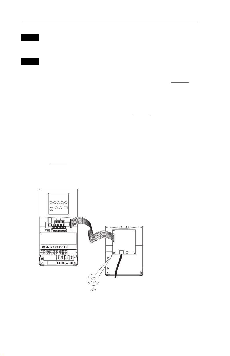
Figure 2 Connecting DSI Ports with Internal Interface Cable
(22-COMM-E EtherNet/IP
Adapter shown as example)
➊
➋
3
PowerFlex 40 Drive
(Frame C shown as
example with cover removed)
PowerFlex 400 Class Frame D and Higher
C. With the adapter board right side up, remove its mounting screw from
the lower left hole. Save the screw for mounting in step F.
D. Connect the Internal Interface cable to the DSI port on the drive (see
Figure 3
E. With the adapter board oriented bottom side up, route the Internal
Interface cable under the adapter, and then to the mating DSI connector
on the adapter.
F. Install the adapter, bottom side up, to the right side of the display board
by snapping it into place. Then insert the adapter mounting screw into
the lower left hole on the board.
Important: Tighten the mounting screw in the adapter’s lower left hole
➌
Back of Required
Special Drive Cover
Item Description
DSI Connector
➊
15.24 cm (6 in.) Internal Interface cable
➋
Network cable
➌
).
to ground the adapter to the drive.
Page 4

Figure 3 Mounting and Connecting the Adapter – PowerFlex 400 Class Frame D and
A
A
Higher
Adapter Installation
Bottom of
Adapter Board
(Side View)
LEDs
Step 5
Step 6
Step 7
Internal Interface
Ribbon Cable
0.9 N-m
(8.0 lb.-in.)
1 Place
PowerFlex 400 Drive (Frame D shown
as example with cover removed)
Connect one end of the network cable to the network. Make sure to use
the proper cable for the network. See the adapter User Manual’s “Related
Documentation” section for appropriate publication(s).
Route the other end of the network cable through the bottom of the
PowerFlex 40/400 Class drive, and connect the cable to the adapter using
the adapter’s mating socket or terminal block. For complete wiring details,
see the adapter User Manual.
Important: Make sure to properly route, wire, and ground the cable.
Always separate the communications wiring from the power
and motor wiring. For more information, see Wiring and
Grounding Guidelines for PWM AC Drives.
Read the adapter User Manual for information to configure and
determine how to apply the network to the host product.
Connector
U.S. Allen-Bradley Drives Technical Support
Tel: (1) 262.512.8176, Fax: (1) 262.512.2222, Email: support@drives.ra.rockwell.com, Online: www.ab.com/support/abdrives
www.rockwellautomation.com
Power, Control and Information Solutions Headquarters
mericas: Rockwell Automation, 1201 South Second Street, Milwaukee, WI 53204-2496 USA, Tel: (1) 414.382.2000, Fax: (1) 414.382.4444
Europe/Middle East/Africa: Rockwell Automation, Vorstlaan/Boulevard du Souverain 36, 1170 Brussels, Belgium, Tel: (32) 2 663 0600, Fax: (32) 2 663 0640
sia Pacific: Rockwell Automation, Level 14, Core F, Cyberport 3, 100 Cyberport Road, Hong Kong, Tel: (852) 2887 4788, Fax: (852) 2508 1846
Publication 22COMM-IN002A-EN-P – January, 2008 P/N 376924-P01
Copyright © 2008 Rockwell Automation, Inc. All rights reserved. Printed in USA.
 Loading...