

Page 1
Installation Instructions
Mounting Channels
PowerFlex 755 Transition Section and Splicing Kit for Floormount Drives and CENTERLINE 2100 Motor Control Centers
Top ic Pa ge
Introduction, Compatibility 1
Additional Resources 2
What the Kits Contain 2
Remove Power from All Equipment 3
Approximate Dimensions 4
Preparing the Transition Section 5
Joining Drive, Transition Section, and MCC 6
Left-side Kit Assembly 7
Right-side Kit Assembly 14
Specifications 25
Introduction
Compatibility
This document explains the recommended procedures that you should use when
joining and splicing a PowerFlex® 755 Floor-mount drive, Frames 8…10, with a
CENTERLINE® 2100 Motor Control Center (MCC).
Before you begin, familiarize yourself with the installation requirements and
recommendations for both the PowerFlex 755 drive and the CENTERLINE
2100 MCC.
The transition section and splicing kit is designed to join together a PowerFlex
755 floor-mount drive and a CENTERLINE 2100 MCC column with or
without 1.5 inch mounting channels.
Diagrams in this publication show the mounting channels installed. Mounting
channels will not be used in all installations.
Page 2
PowerFlex 755 Transition Section and Splicing Kit for Floor-mount Drives and CENTERLINE 2100 Motor Control Centers
Additional Resources
What the Kits Contain
The following table lists publications that provide general PowerFlex 755 drives
and CENTERLINE 2100 MCC related information.
Resource Description
PowerFlex 750-Series AC Drives Installation Instructions,
publication 750-IN001
CENTERLINE 2100 Low Voltage Motor Control Centers
Installation Instructions, publication 2100-IN012
CENTERLINE Motor Control Centers NEMA Type 12 Sealing
Instructions, publication 2100-IN037
Provides detailed information on:
• Installation requirements
• Additional safety requirements
• Drive assembly removal and handling
• Approximate dimensions
Provides detailed information on:
• Installation requirements
• Handling instructions
• Approximate dimensions
Provides detailed information on:
• Sealing NEMA Type 12 structures
You can view or download publications at
http://www.rockwellautomation.com/literature/
.
To order paper copies of technical documentation, contact your local AllenBradley distributor or Rockwell Automation sales representative.
A complete installation requires one transition section and one bus bar splicing
kit. Depending on the catalog number ordered, the kit will be a left-side mount or
a right-side mount relative to the drive. Kits include all joining and splicing
hardware. An IP20, NEMA/UL Type 1 enclosure results when kits are installed
according to these instructions. If a NEMA Type 12 structure is required, follow
the CENTERLINE Motor Control Centers NEMA Type 12 Sealing
Instructions, publication 2100-IN037
.
Left-side Kits Right-side Kits Amp
20-750-XBUS-LHNB-1200 20-750-XBUS-RHNB-1200 1200 Standard (15 and 20 in. deep) For use
20-750-XBUS-LHNB-2000 20-750-XBUS-RHNB-2000 2000 Standard (15 and 20 in. deep)
20-750-XBUS-LHNB-3000 20-750-XBUS-RHNB-3000 3000 Standard (15 and 20 in. deep)
20-750-XBUS-LHBB-1200 20-750-XBUS-RHBB-1200 1200 Bumped Back (20 in. deep)
20-750-XBUS-LHBB-2000 20-750-XBUS-RHBB-2000 2000 Bumped Back (20 in. deep)
20-750-XBUS-LHBB-3000 20-750-XBUS-RHBB-3000 3000 Bumped Back (20 in. deep)
20-750-XSEC-LH-20G
20-750-XBUS-LLNB-1200 20-750-XBUS-RLNB-1200 1200 Standard (15 and 20 in. deep) For use
20-750-XBUS-LLNB-2000 20-750-XBUS-RLNB-2000 2000 Standard (15 and 20 in. deep)
20-750-XBUS-LLNB-3000 20-750-XBUS-RLNB-3000 3000 Standard (15 and 20 in. deep)
20-750-XBUS-LLBB-1200 20-750-XBUS-RLBB-1200 1200 Bumped Back (20 in. deep)
20-750-XBUS-LLBB-2000 20-750-XBUS-RLBB-2000 2000 Bumped Back (20 in. deep)
20-750-XBUS-LLBB-3000 20-750-XBUS-RLBB-3000 3000 Bumped Back (20 in. deep)
(1) Hardware is included to install the optional 1.5 mounting channel.
(2) The 15 in. deep transition section can be mounted on the left side or the right side of the PowerFlex 755 drive cabinet.
(1)
20-750-XSEC-RH-20G
20-750-XSEC-BH-15G
(2)
Rating
(1)
N/A 20 in. deep transition section N/A
N/A 15 in. deep transition section N/A
MCC Bus Bar Position Mounting
Channel
with MCCs
that have
1.5 inch
mounting
channels.
with MCCs
that do not
have
mounting
channels.
2 Rockwell Automation Publication 750-IN027C-EN-P - November 2013
Page 3
PowerFlex 755 Transition Section and Splicing Kit for Floor-mount Drives and CENTERLINE 2100 Motor Control Centers
Frame 8 AC Input Drive Shown
Left-side Kits
Follow all steps including the Left-side Kit Assembly sequence for 20 in. deep
left-side-mount transition sections and the 15 in. deep left- or right-side-mount
transition section.
Right-side Kits
Follow all steps including Right-side Kit Assembly sequence for 20 in. deep rightside-mount transition sections and the 15 in. deep left- or right-side-mount
transition section.
Remove Power from All
Equipment
Remove power from all equipment before proceeding with these instructions.
Refer to the product’s installation instructions and review all safety precautions
before performing work on this equipment.
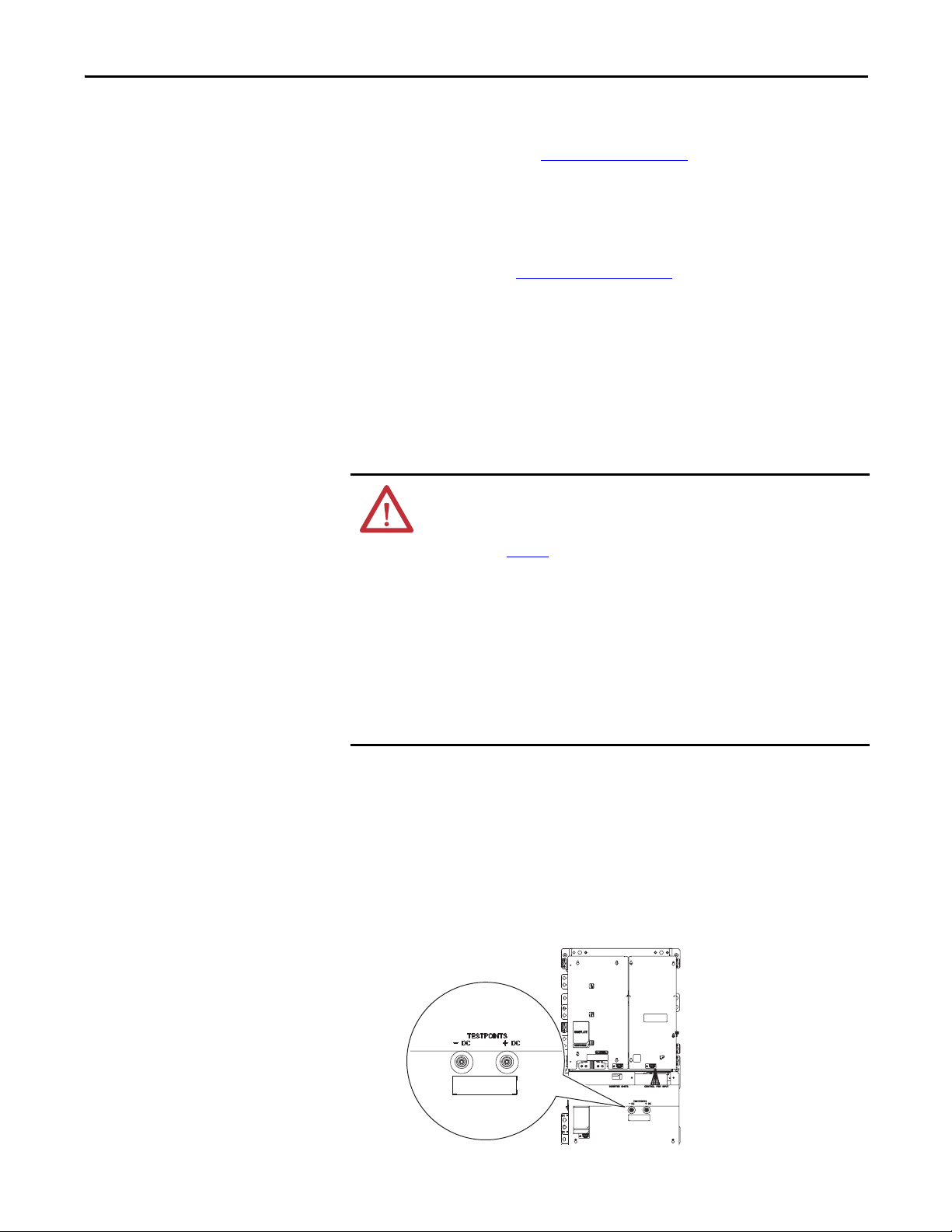
PowerFlex 755 Drive
ATT EN TI ON : To avoid an electric shock hazard, verify that the voltage on the
bus capacitors has discharged completely before servicing. Measure the DC bus
voltage at the -DC and +DC TESTPOINT sockets on the front of the power
module (see Figure 1
Remove power before making or breaking cable connections. When you remove or
insert a cable connector with power applied, an electrical arc may occur. An
electrical arc can cause personal injury or property damage by:
• sending an erroneous signal to your system’s field devices, causing unintended
machine motion
• causing an explosion in a hazardous environment
Electrical arcing causes excessive wear to contacts on both the module and its
mating connector. Worn contacts may create electrical resistance.
1. Turn off and lock out all input power, including any and all external power
sources.
for location).
2. Wait 15 minutes and verify that there is no voltage at the drive’s input
power terminals.
3. Measure the DC bus voltage at the -DC and +DC TESTPOINT sockets
on the front of the power module.
Figure 1 - PowerFlex Drive -DC and +DC Testpoint Sockets
Rockwell Automation Publication 750-IN027C-EN-P - November 2013 3
Page 4
PowerFlex 755 Transition Section and Splicing Kit for Floor-mount Drives and CENTERLINE 2100 Motor Control Centers
CENTERLINE 2100 MCC
ATT EN TI ON : De-energize all units before installing or removing.
When installing or removing MCC units, when possible, deenergize, lockout, and
tag-out all sources of power to the MCC.
ATT EN TI ON : De-energize all power sources to the motor control center before
joining and splicing with the drive. Failure to de-energize all power sources can
result in severe injury or death. Using a voltmeter, verify that the MCC remote
power sources are disconnected.
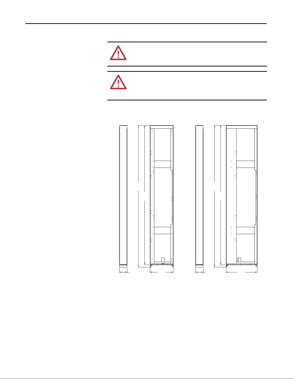
Approximate Dimensions
Dimensions are in millimeters and (inches).
2323
(91.5)
2285
(90.0)
2323
(91.5)
2285
(90.0)
127
(5.0)
20-750-XSEC-BB-20G
4 Rockwell Automation Publication 750-IN027C-EN-P - November 2013
381
(15.0)
127
(5.0)
20-750-XSEC-RH-20G
20-750-XSEC-LH-20G
508
(20.0)
Page 5
PowerFlex 755 Transition Section and Splicing Kit for Floor-mount Drives and CENTERLINE 2100 Motor Control Centers
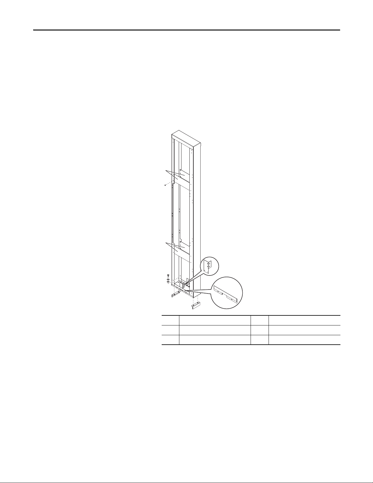
Preparing the Transition
Section
1. Remove and discard the four shipping plates ➊.
2. Remove the masking from the ground terminals
➋.
MCC Columns with Mounting Channels
3. Remove the spacer ➌ on the side of the transition section that will attach to
the MCC column.
MCC Columns without Mounting Channels
3. Remove the mounting channels ➍ from the transition section.
➊
x 4
➊
x 4
➍
No. Description No. Description
➊ Shipping plates ➌ Spacer
➋ Ground Terminal ➍ Mounting Channels
➋
➌
Rockwell Automation Publication 750-IN027C-EN-P - November 2013 5
Page 6
PowerFlex 755 Transition Section and Splicing Kit for Floor-mount Drives and CENTERLINE 2100 Motor Control Centers
IMPORTANT
Joining Drive, Transition
Section, and MCC
Physical restrictions at your installation may not allow the following sequence to
be followed exactly as stated.
Step 1: Remove Drive Assembly
The PowerFlex 755 drive assembly must be removed to access side panels and
horizontal bus bars.
For detailed information on removing and handling the PowerFlex 755 drive
assembly, refer to the PowerFlex 750-Series AC Drives Installation Instructions,
publication 750-IN001
ATT EN TI ON : This drive has a high center of gravity and a tip-over hazard exists.
To guard against death, serious personal injury, and/or equipment damage, do
not subject the drive to high rates of acceleration or deceleration while
transporting. Do not push or pull above the points indicated on the drive.
. Special equipment is required.
Step 2: Remove Plug-in Units, Support Pans, and Access Covers
All plug-in units and support pans must be removed to access side panels and
horizontal bus bars.
ATT EN TI ON : Plug-in MCC units may be heavy or awkward to handle. Use an
assistant or a platform lift device if necessary to help you handle the unit
To complete plug-in unit removal refer to Installing Units with Horizontal
Operating Handles, publication 2100-IN060
Operating Handles, publication 2100-IN014
ATT EN TI ON : MCCs are top and front heavy. To avoid personal injury or
structural damage, never attempt to lift or move the MCC by any means other
than the methods outlined in Receiving and Storing Motor Control Centers,
publication 2100-IN040
If you’re installing a left-mount kit, see page 7
If you’re installing a right-mount kit, see page 14
After completing these instructions, refer to the publications listed on this page and
under Additional Resources
equipment and components.
.
on page 2 for detailed information on reinstalling
, and Installing Units with Vertical
.
.
.
6 Rockwell Automation Publication 750-IN027C-EN-P - November 2013
Page 7
PowerFlex 755 Transition Section and Splicing Kit for Floor-mount Drives and CENTERLINE 2100 Motor Control Centers
➊
➊
➋
➋
➌
Cabinet door and internal components
omitted for clarity.
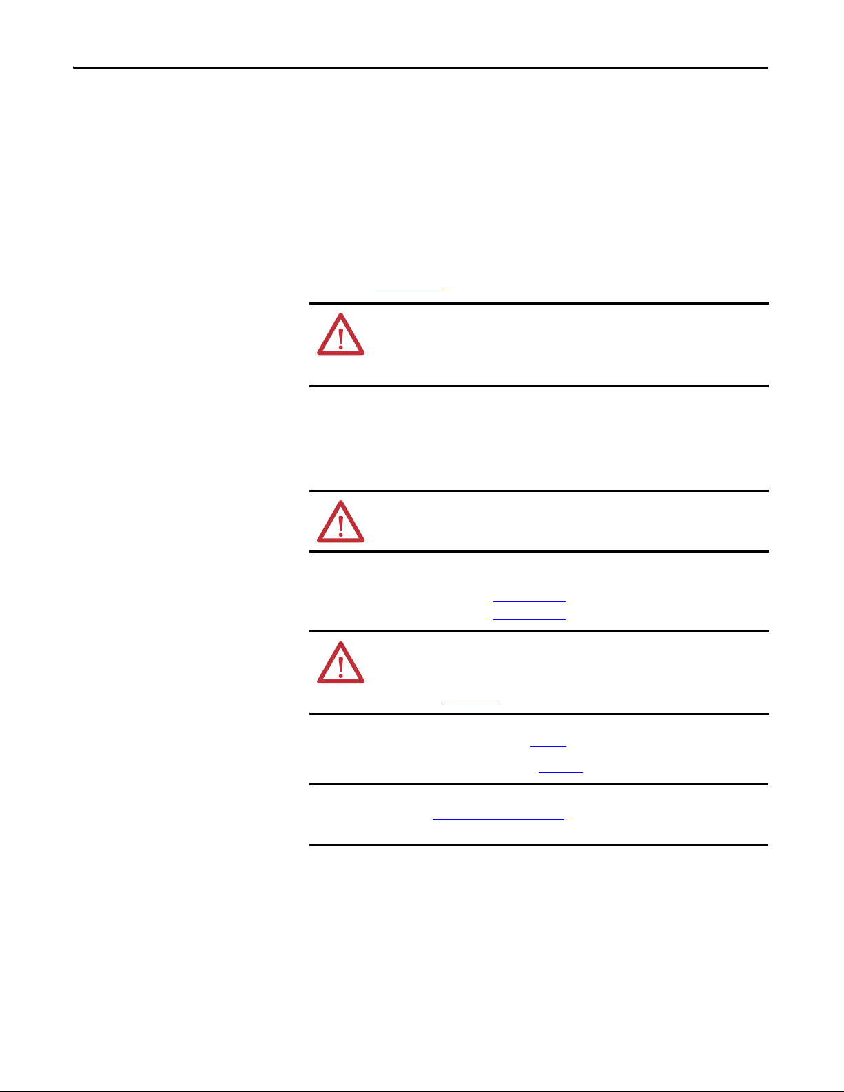
Left-side Kit Assembly
Step 3 (Left): Join Transition Section to Left Side of Drive Cabinet
1. Remove panels from the left side of the PowerFlex 755 drive cabinet.
No. Description
➊ Top and bottom rear-wireway panels.
➋ Top and bottom PE bus-bar access panels.
➌ Main horizontal bus-bar access panel.
2. Align the left transition section with the drive cabinet.
➊
➊
➊
➊
➊
➊
➊
➊
Rockwell Automation Publication 750-IN027C-EN-P - November 2013 7
Page 8
PowerFlex 755 Transition Section and Splicing Kit for Floor-mount Drives and CENTERLINE 2100 Motor Control Centers
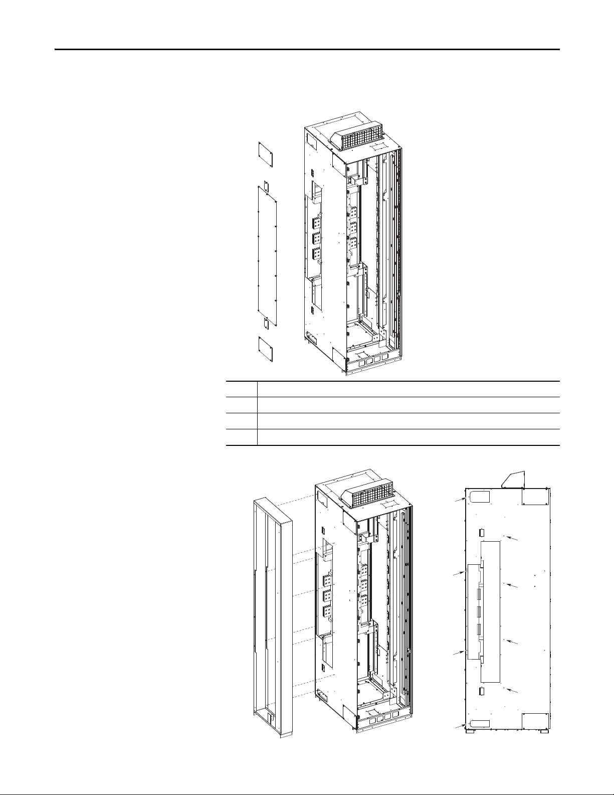
IMPORTANT
3. Bring the transition section and drive cabinet together.
4. Pass the M6 x 16 mm hex-head thread-forming screws from inside the
transition section through the joining holes and engage the screws with the
➊ holes in the drive cabinet.
5. Make sure cabinets are level and pushed together tightly.
6. Tighten the screws in a uniform pattern.
Do not use hardware to draw cabinets together.
M6
6.2 N•m (55 lb•in)
10 mm
8 Rockwell Automation Publication 750-IN027C-EN-P - November 2013
Page 9

PowerFlex 755 Transition Section and Splicing Kit for Floor-mount Drives and CENTERLINE 2100 Motor Control Centers
Unit doors, support pans, and access
covers omitted for clarity.
Step 4 (Left): Join MCC Column to Left Side of Transition Section
1. Remove the closing plates from the right side of the MCC column.
➋
➊
➌
➋
➊
No. Description
➊ Top and bottom front-wireway closing plates.
➋ Top and bottom rear-wireway closing plates.
➌ Main horizontal bus-bar closing plates.
Rockwell Automation Publication 750-IN027C-EN-P - November 2013 9
Page 10

PowerFlex 755 Transition Section and Splicing Kit for Floor-mount Drives and CENTERLINE 2100 Motor Control Centers
➋
➊
➊
➊
➊
➊
➊
MCC side of transition section
2. Align the MCC column with the left transition section.
3. Bring the MCC column, transition section, and drive cabinet together.
4. Pass the 1/4-20 x 0.5 in. hex-head thread-forming screws from inside the
MCC column through the joining holes and engage the screws with the
➊
holes in the transition section.
5. Pass the 1/4-20 x 1 in. screw from inside the MCC column through the
transition section joining hole
➋ and secure with the 1/4-20 steel nut.
10 Rockwell Automation Publication 750-IN027C-EN-P - November 2013
Page 11

PowerFlex 755 Transition Section and Splicing Kit for Floor-mount Drives and CENTERLINE 2100 Motor Control Centers
IMPORTANT
6. Make sure cabinets are level and pushed together tightly.
7. Tighten the screws in a uniform pattern.
Do not use hardware to draw cabinets together.
1/4-20
6.2 N•m (55 lb•in)
10 mm
Rockwell Automation Publication 750-IN027C-EN-P - November 2013 11
Page 12

PowerFlex 755 Transition Section and Splicing Kit for Floor-mount Drives and CENTERLINE 2100 Motor Control Centers
IMPORTANT
Step 5 (Left): Join PE Bus Bar and Grounding Bracket
1. Align the protective earth (PE) conductor splicing hardware with the
transition section grounding bracket.
2. Insert and tighten the 1/4-20 x 1 in. screws.
Do not grease or lubricate hardware.
1/4-20 x 1 in.
7.3 N•m (65 lb•in)
10 mm
12 Rockwell Automation Publication 750-IN027C-EN-P - November 2013
Page 13

PowerFlex 755 Transition Section and Splicing Kit for Floor-mount Drives and CENTERLINE 2100 Motor Control Centers
1/4-20
7.3 N•m (65 lb•in)
10 mm
➊
➌
➋
1/4-20 x 1 in.
1/4-20 x 1 in.
1/4-20 x 1.25 in.
Step 6 (Left): Connect PE Splicing Cables
1. Pass the cables through the bottom wireway openings.
2. Connect the PE splicing cables between the MCC and drive PE bus bars.
No. Description Hardware
➊ 1200A with 25.4 mm (1 in.) bus bar. Requires two splice cables.
➋ 2000A with 25.4 mm (1 in.) bus bar. Requires two splice cables.
2000A with 50.8 mm (2 in.) bus bar. Requires three splice cables.
➌ 3000A with 50.8 mm (2 in.) bus bar. Requires three splice cables.
See Tab le 3
required hardware.
for a list of
Rockwell Automation Publication 750-IN027C-EN-P - November 2013 13
Page 14

PowerFlex 755 Transition Section and Splicing Kit for Floor-mount Drives and CENTERLINE 2100 Motor Control Centers
Unit doors, support pans, and access
covers omitted for clarity.
➊
➋
➊
➊
➊
➊
➊
MCC column
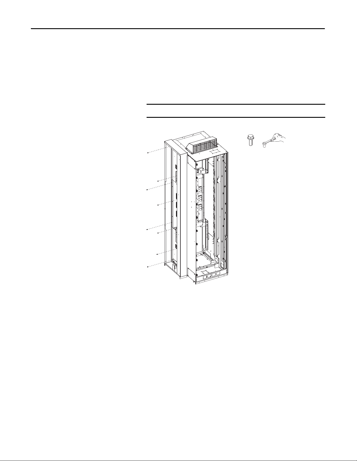
Right-side Kit Assembly
Step 3 (Right): Join Transition Section to Left Side of MCC Column
1. Remove the closing plates from the left side of the MCC column.
➋
➊
➌
➋
➊
No. Description
➊ Top and bottom front-wireway closing plates.
➋ Top and bottom rear-wireway closing plates.
➌ Main horizontal bus-bar closing plates.
2. Align the right transition section with the MCC column
14 Rockwell Automation Publication 750-IN027C-EN-P - November 2013
Page 15

PowerFlex 755 Transition Section and Splicing Kit for Floor-mount Drives and CENTERLINE 2100 Motor Control Centers
IMPORTANT
1/4-20
6.2 N•m (55 lb•in)
10 mm
3. Bring the transition section and MCC column together.
4. Pass the 1/4-20 x 0.5 in. hex-head thread-forming screws from inside the
transition section through the joining holes and engage the screws with the
➊ holes in the MCC column.
5. Pass the 1/4-20 x 1 in. screw from inside the MCC column through the
transition section joining hole
➋ and secure with the 1/4-20 steel nut.
6. Make sure cabinets are level and pushed together tightly.
7. Tighten the screws in a uniform pattern.
Do not use hardware to draw cabinets together.
Rockwell Automation Publication 750-IN027C-EN-P - November 2013 15
Page 16

PowerFlex 755 Transition Section and Splicing Kit for Floor-mount Drives and CENTERLINE 2100 Motor Control Centers
IMPORTANT
Step 4 (Right): Join PE Bus Bar and Grounding Bracket
1. Align the protective earth (PE) conductor splicing hardware with the
transition section grounding bracket.
2. Insert and tighten the 1/4-20 x 1 in. screws.
Do not grease or lubricate hardware.
1/4-20 x 1 in.
7.3 N•m (65 lb•in)
10 mm
16 Rockwell Automation Publication 750-IN027C-EN-P - November 2013
Page 17

PowerFlex 755 Transition Section and Splicing Kit for Floor-mount Drives and CENTERLINE 2100 Motor Control Centers
Cabinet door and internal components
omitted for clarity.
Step 5 (Right): Join Drive Cabinet to Left Side of Transition Section
1. Remove panels from the right side of the PowerFlex 755 drive cabinet.
➊
➋
➌
➋
No. Description
➊ Top and bottom rear-wireway panels.
➋ Top and bottom PE bus-bar access panels.
➌ Main horizontal bus-bar access panel.
➊
Rockwell Automation Publication 750-IN027C-EN-P - November 2013 17
Page 18

PowerFlex 755 Transition Section and Splicing Kit for Floor-mount Drives and CENTERLINE 2100 Motor Control Centers
2. Align the right transition section with the drive cabinet.
➊
➊
➊
➊
➊
➊
➊
➊
3. Bring the transition section, MCC column, and drive cabinet together.
4. Pass the M6 x 16 mm hex-head thread-forming screws from inside the
drive cabinet through the joining holes and engage the screws with the
holes in the transition section.
➊
18 Rockwell Automation Publication 750-IN027C-EN-P - November 2013
Page 19

PowerFlex 755 Transition Section and Splicing Kit for Floor-mount Drives and CENTERLINE 2100 Motor Control Centers
IMPORTANT
1/4-20
7.3 N•m (65 lb•in)
10 mm
➊
➌
➋
1/4-20 x 1 in.
1/4-20 x 1 in.
1/4-20 x 1.25 in.
5. Make sure cabinets are level and pushed together tightly.
6. Tighten the screws in a uniform pattern.
Do not use hardware to draw cabinets together.
M6
6.2 N•m (55 lb•in)
10 mm
Step 6 (Right): Connect PE Splicing Cables
1. Pass the cables through the bottom wireway openings.
2. Connect the PE splicing cables between the MCC and drive PE bus bars.
No. Description Hardware
➊ 1200A with 25.4 mm (1 in.) bus bar. Requires two splice cables.
➋ 2000A with 25.4 mm (1 in.) bus bar. Requires two splice cables.
2000A with 50.8 mm (2 in.) bus bar. Requires three splice cables.
➌ 3000A with 50.8 mm (2 in.) bus bar. Requires three splice cables.
Rockwell Automation Publication 750-IN027C-EN-P - November 2013 19
See Tab le 3
required hardware.
for a list of
Page 20

PowerFlex 755 Transition Section and Splicing Kit for Floor-mount Drives and CENTERLINE 2100 Motor Control Centers
IMPORTANT
Main Horizontal Bus -bar
Main Horizontal
Bus-bar Splicing Bars
Flat Washers
One-Piece Nut and Conical Spring Washer
Bus Clamps
Front
Step 7: Join Horizontal Bus and Splicing Bars
Splicing kits will contain either two or four sets of hardware per splice bar,
depending on the current rating of the horizontal bus. Assemble hardware as
depicted in Figure 2
listed in Ta bl e 1
Figure 2 - Splicing Hardware Configuration Detail
and uniformly tighten splice kit hardware to the final torque
.
Note for NO-OX-ID: If you’re using corrosion inhibitor on bus bars, do not get
any on the bus splicing hardware. It will prevent the hardware from being
properly torqued. Damage may occur.
20 Rockwell Automation Publication 750-IN027C-EN-P - November 2013
See Tab le 3 for main horizontal bus-bar splicing bar dimensions.
Page 21

PowerFlex 755 Transition Section and Splicing Kit for Floor-mount Drives and CENTERLINE 2100 Motor Control Centers
Standard Bus-bar Position
MCC Horizontal Bus
PowerFlex Drive
Horizontal Bus
Front
MCC Horizontal Bus
PowerFlex Drive
Horizontal Bus
Front
MCC Horizontal Bus
PowerFlex Drive
Horizontal Bus
Front
Left-side Standard Bus-bar Splice Kits
Figure 3 - 1200A (Kit No. 20-750-XBUS-LHNB/LLNB-1200) - Standard Bus-bar Position
3/8-16 x 1.38 in.
Figure 4 - 2000A (Kit No. 20-750-XBUS-LHNB/LLNB-2000) - Standard Bus-bar Position
3/8-16 x 2.25 in.
Figure 5 - 3000A (Kit No. 20-750-XBUS-LHNB/LLNB-3000) - Standard Bus-bar Position
3/8-16 x 2.75 in.
3/8-16 x 2.25 in.
Rockwell Automation Publication 750-IN027C-EN-P - November 2013 21
Page 22

PowerFlex 755 Transition Section and Splicing Kit for Floor-mount Drives and CENTERLINE 2100 Motor Control Centers
Bumped-Back Bus-bar Position
3/8-16 x 1.38 in.
MCC Horizontal Bus
PowerFlex Drive
Horizontal Bus
Front
3/8-16 x 2.25 in.
MCC Horizontal Bus
Power Flex Dri ve
Horizontal Bus
Front
MCC Horizontal Bus
Power Flex Dri ve
Horizontal Bus
Front
Left-side Bumped-Back Bus-bar Splice Kits
Figure 6 - 1200A (Kit No. 20-750-XBUS-LHBB/LLBB-1200) - Bumped-Back Bus-bar Position
Figure 7 - 2000A (Kit No. 20-750-XBUS-LHBB/LLBB-2000) - Bumped-Back Bus-bar Position
Figure 8 - 3000A (Kit No. 20-750-XBUS-LHBB/LLBB-3000) - Bumped-Back Bus-bar Position
3/8-16 x 2.25 in.
3/8-16 x 2.75 in.
22 Rockwell Automation Publication 750-IN027C-EN-P - November 2013
Page 23

PowerFlex 755 Transition Section and Splicing Kit for Floor-mount Drives and CENTERLINE 2100 Motor Control Centers
Standard Bus-bar Position
3/8-16 x 1.38 in.
MCC Horizontal Bus
PowerFlex Drive
Horizontal Bus
Front
MCC Horizontal Bus
PowerFlex Drive
Horizontal Bus
Front
MCC Horizontal Bus
PowerFlex Drive
Horizontal Bus
Front
Right-side Standard Bus-bar Splice Kits
Figure 9 - 1200A (Kit No. 20-750-XBUS-RHNB/RLNB-1200) - Standard Bus-bar Position
Figure 10 - 2000A (Kit No. 20-750-XBUS-RHNB/RLNB-2000) - Standard Bus-bar Position
3/8-16 x 2.25 in.
Figure 11 - 3000A (Kit No. 20-750-XBUS-RHNB/RLNB-3000) - Standard Bus-bar Position
3/8-16 x 2.25 in.
3/8-16 x 2.75 in.
Rockwell Automation Publication 750-IN027C-EN-P - November 2013 23
Page 24

PowerFlex 755 Transition Section and Splicing Kit for Floor-mount Drives and CENTERLINE 2100 Motor Control Centers
Bumped-Back Bus-bar Position
3/8-16 x 1.38 in.
MCC Horizontal Bus
PowerFlex Drive
Horizontal Bus
Front
MCC Horizontal Bus
PowerFlex Drive
Horizontal Bus
Front
MCC Horizontal Bus
PowerFlex Drive
Horizontal Bus
Front
Right-side Bumped-Back Bus-bar Splice Kits
Figure 12 - 1200A (Kit No. 20-750-XBUS-RHBB/RLBB-1200) - Bumped-Back Bus-bar Position
Figure 13 - 2000A (Kit No. 20-750-XBUS-RHBB/RLBB-2000) - Bumped-Back Bus-bar Position
3/8-16 x 2.25 in.
Figure 14 - 3000A (Kit No. 20-750-XBUS-RHBB/RLBB-3000) - Bumped-Back Bus-bar Position
3/8-16 x 2.25 in.
3/8-16 x 2.75 in.
24 Rockwell Automation Publication 750-IN027C-EN-P - November 2013
Page 25

PowerFlex 755 Transition Section and Splicing Kit for Floor-mount Drives and CENTERLINE 2100 Motor Control Centers
Specifications
Tighten all bus connections with a torque wrench and socket according to
intervals established by your maintenance policy. If a torque wrench is not
available, tighten until the conical spring washer is flat. Do not grease or lubricate
the hardware.
Table 1 - Torque Requirements
Description Hardware Torque
Transition section to drive cabinet joining screws M6 6.2 N•m (55 lb•in)
Transition section to MCC column joining screws 1/4-20 6.2 N•m (55 lb•in)
Protective earth (PE) conductor splice connection 1/4-20 7.3 N•m (65 lb•in)
Main horizontal bus-bar splice connection 3/8-16 38 N•m (336 lb•in)
Table 2 - Horizontal Bus Required Splice Hardware
Amp Rating Description Quantity
1200 3/8-16 x 1.38 in. bus clamp assembly 12
3/8 flat washer 24
3/8-16 one-piece nut and conical spring washer 24
2000 3/8-16 x 2.25 in. bus clamp assembly 12
3/8 flat washer 24
3/8-16 one-piece nut and conical spring washer 24
3000 3/8-16 x 2.25 in. bus clamp assembly 6
3/8-16 x 2.75 in. bus clamp assembly 6
3/8 flat washer 24
3/8-16 one-piece nut and conical spring washer 24
Table 3 - PE Bus Required Splice Hardware
PE Bus Bar Width Amp Rating Description Quantity
25.4 mm (1.0 in.) 1200 and 2000 762 mm (30 in.) 250 MCM cable 2
1/4-20 x 1.25 in. hex-head cap screw 1
1/4-20 x 1.0 in. hex-head cap screw 3
1/4 flat washer 7
1/4 conical spring washer 4
1/4-20 G5 hex nut 3
50.8 mm (2.0 in.) 2000 and 3000 762 mm (30 in.) 250 MCM cable 2
914 mm (36 in.) 250 MCM cable 1
1/4-20 x 1.25 in. hex-head cap screw 1
1/4-20 x 1.0 in. hex-head cap screw 6
1/4 flat washer 10
1/4 conical spring washer 7
1/4-20 G5 hex nut 5
Rockwell Automation Publication 750-IN027C-EN-P - November 2013 25
Page 26

Rockwell Automation Support
Rockwell Automation provides technical information on the Web to assist you in using its products.
At http://www.rockwellautomation.com/support
code and links to software service packs, and a MySupport feature that you can customize to make the best use of these
tools. You can also visit our Knowledgebase at http://www.rockwellautomation.com/knowledgebase
information, support chat and forums, software updates, and to sign up for product notification updates.
, you can find technical manuals, technical and application notes, sample
for FAQs, technical
For an additional level of technical phone support for installation, configuration, and troubleshooting, we offer
Te c h C o n n e c t
representative, or visit http://www.rockwellautomation.com/support/
SM
support programs. For more information, contact your local distributor or Rockwell Automation
.
Installation Assistance
If you experience a problem within the first 24 hours of installation, review the information that is contained in this
manual. You can contact Customer Support for initial help in getting your product up and running.
United States or Canada 1.440.646.3434
Outside United States or Canada Use the Worldwi de Lo cator
local Rockwell Automation representative.
at http://www.rockwellautomation.com/rockwellautomation/support/overview.page, or contact your
New Product Satisfaction Return
Rockwell Automation tests all of its products to help ensure that they are fully operational when shipped from the
manufacturing facility. However, if your product is not functioning and needs to be returned, follow these procedures.
United States Contact your distributor. You must provide a Customer Support case number (call the phone number above to obtain one) to your
distributor to complete the return process.
Outside United States Please contact your local Rockwell Automation representative for the return procedure.
Documentation Feedback
Your comments will help us serve your documentation needs better. If you have any suggestions on how to improve this
document, complete this form, publication RA-DU002
U.S. Allen-Bradley Drives Technical Support - Tel: (1) 262.512.8176, Fax: (1) 262.512.2222, E-mail: support@drives.ra.rockwell.com
Online: www.ab.com/support/abdrives
Allen-Bradley, Rockwell Software, Rockwell Automation, PowerFlex, RSLinx, DriveExplorer, DriveExecutive, ControlFLASH, and TechConnect are trade marks of Rockwell Automation, Inc.
Trademarks not belonging to Rockwell Automation are property of their respective companies.
Publication 750-IN027C-EN-P - November 2013
Supersedes Publication 750-IN027B-EN-P - February 2013 Copyright © 2013 Rockwell Auto mation, Inc. All rights reserved. Pr inted in the U.S.A.
, available at http://www.rockwellautomation.com/literature/.
 Loading...