

Page 1
Installation Instructions
PowerFlex® 750-Series Roll-Out Cart
ATTENTION: Because drive installations can vary, the PowerFlex
750-Series Roll-out Cart may require adjustment prior to use. Refer to the
PowerFlex 750-Series AC Drive Installation Instructions, publication
750-IN001 for detailed setup information. Familiarize yourself with all
hazards associated with using the Roll-out Cart before attempting to
remove the drive from the cabinet.
ATTENTION: The Roll-out Cart is used with a drive that has a high center
of gravity and a tip over hazard exists. To guard against death, serious
personal injury, and/or equipment damage, do not subject the drive to
high rates of acceleration or deceleration while transporting. Do not push
or pull above the points indicated on the drive.
ATTENTION: To avoid an electric shock hazard, verify that the voltage on
the bus capacitors has discharged completely before servicing. After
removing power to the drive, wait 5 minutes for the bus capacitors to
discharge. Measure the DC bus voltage at the DC+ and DC- TESTPOINT
sockets on the front of the power module. The voltage must be zero.
ATTENTION: HOT surfaces can cause severe burns. After disconnecting
power allow time for cooling.
ATTENTION: This drive contains ESD (Electrostatic Discharge) sensitive
parts and assemblies. Static control precautions are required when
installing, testing, servicing or repairing this assembly. Component
damage may result if ESD control procedures are not followed. If you are
not familiar with static control procedures, reference Guarding Against
Electrostatic Damage, publication 8000-4.5.2 or any other applicable ESD
protection handbook.
ATTENTION: Hazard of permanent eye damage exists when using optical
transmission equipment. This product emits intense light and invisible
radiation. Do not look into module ports or fiber optic cable connectors.
Finding Specific Information
IMPORTANT
Take precautions when using the Roll-out Cart to move the drive.
• Only use the Roll-out Cart to move the drive a short distance in order to
gain access to the cabinet interior.
• Do not attempt to move the drive on the Roll-out Cart with the handle
alone. The Roll-out Cart handle is designed for positioning the empty
cart.
• Only use the cart on a smooth and level surface.
• Ensure the path for the cart is clear of debris and obstacles.
• Avoid sloped and rough surfaces.
• Always move the drive slowly.
For detailed information on using the Roll-out Cart with the drive refer to the
PowerFlex 750-Series Installation Instructions, publication 750-IN001 available
online at: www.rockwellautomation.com/literature
Page 2
2
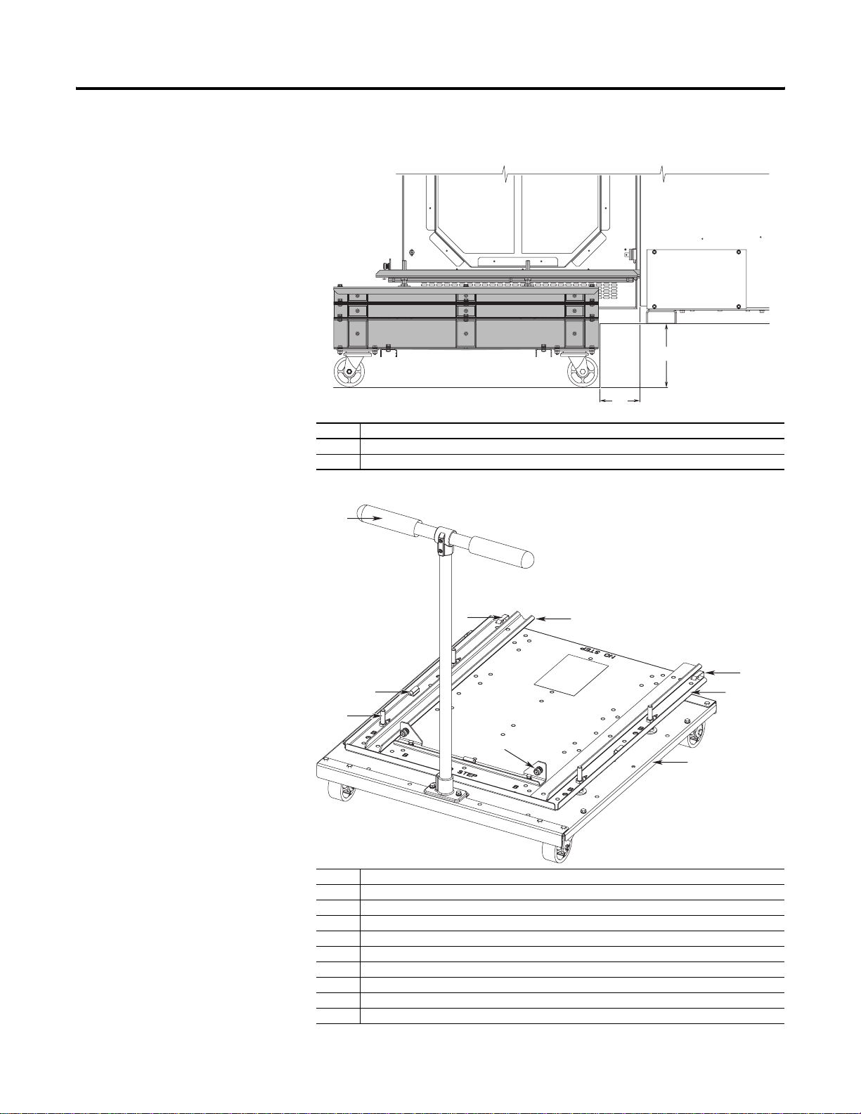
Prepare the Roll-out Cart
The 20-750-CART1-F8 Roll-out Cart is required to remove the Frame 8 drive
from the cabinet. It can be adjusted for reach and height.
➋
➊
No. Description
➊ Adjustment for Curb Offset/Reach: 0…114 mm (0…4.5 in.)
➋ Adjustable Curb Height: 0…182 mm (0…7.2 in.)
Figure 1 - Roll-out Cart Features
➌
➍
➎
➍
➋
➏
➊
➑
➐
No. Description
➊ Threaded studs and nuts allow precision height and leveling adjustments (four positions)
➋ Bubble levels help with fine adjustment of the cart deck (three positions)
➌ Handle
➍ Retaining clips positively engage the cart with the drive cabinet (two positions)
➎ Alignment track keeps the drive in the correct position
➏ Cart deck
➐ Cart chassis
➑ Drive stop and capture screws
➒ Hardware for assembling I-beam spacers (not shown)
Rockwell Automation Publication 750-IN014A-EN-P - August 2010
Page 3
3
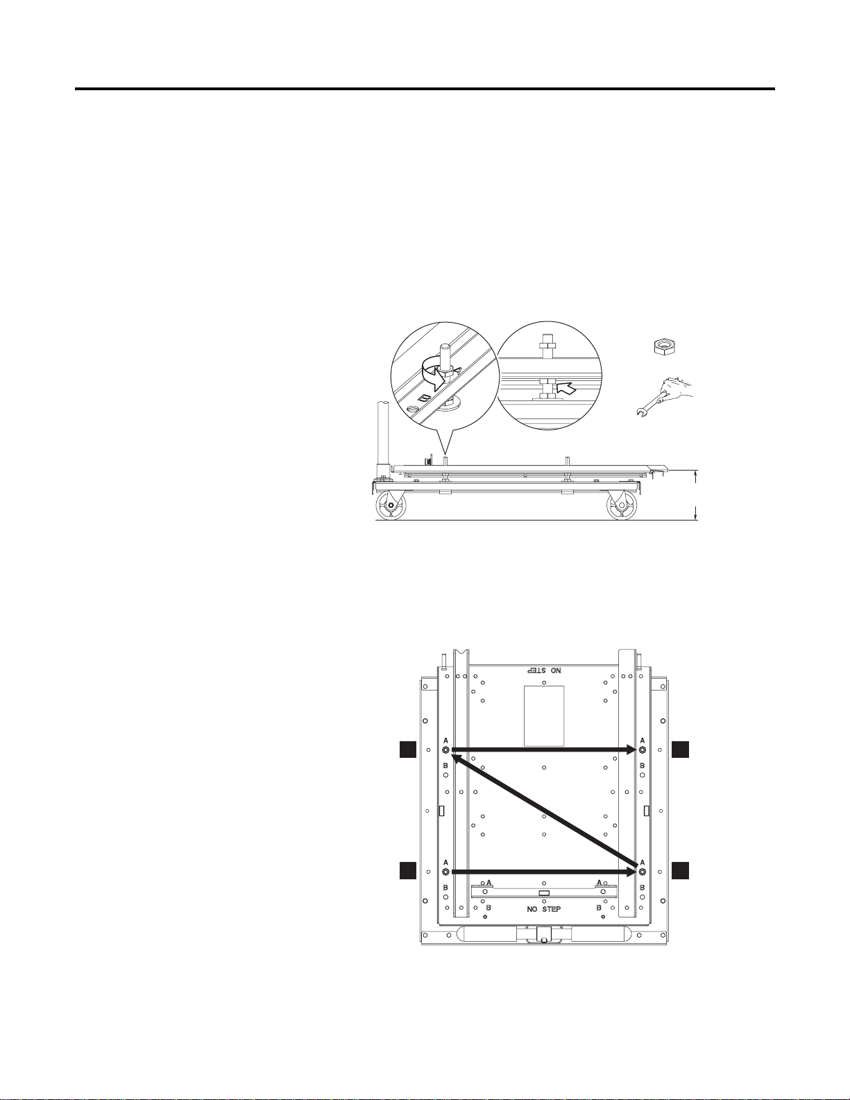
Adjust Roll-Out Cart Height Using Threaded Studs and Nuts
The height of the Roll-out Cart deck can be adjusted using the threaded leveling
studs and nuts.
• Maximum height = 155.5 mm (6.1 in.)
• Minimum height = 116 mm (4.6 in.)
• Adjustment range = 30 mm (1.2 in.) up, 9.5 mm (0.4 in.) down from the
factory setting of 125.5 mm (4.9 in.)
1. Loosen and back off the top nuts on the four threaded leveling studs ➊.
➊
➋
M10 x 1.5
17 mm
125.5 +30.0/-9.5
(4.9 +1.2/-0.4)
2. Turn the bottom supporting nuts to raise or lower the cart deck ➋. Right
hand nut rotation lowers the deck. Left hand rotation raises the deck.
Make uniform half-turn adjustments to each of the four threaded studs in
an alternating pattern to help prevent binding and maintain a level
orientation.
3
1
3. At the desired height, ensure the deck is level using the three bubble levels.
4. Tighten the top nuts.
Rockwell Automation Publication 750-IN014A-EN-P - August 2010
4
2
Page 4

4
Adjust Roll-Out Cart Height Using Spacers
The height of the Roll-out Cart deck can be adjusted using the I-beam spacers
provided.
➊
➋
No. Description
➊ Four 38.1 mm (1.5 in.) spacers
➋ Two 76.2 mm (3.0 in.) spacers
Spacer Height Combinations
Each of the base heights below have adjustment range of +30.0 mm (1.2 in.) and
-9.5 mm (0.4 in.).
125.5
(4.9)
163.6
(6.4)
201.7
(7.9)
Rockwell Automation Publication 750-IN014A-EN-P - August 2010
239.8
(9.4)
277.9
(10.9)
Page 5

1. Remove the Roll-out Cart deck by removing the top nuts of the four
threaded leveling studs.
5
M10 x 1.5
17 mm
2. Lift the deck off of the four threaded leveling studs.
Rockwell Automation Publication 750-IN014A-EN-P - August 2010
Page 6

6
3. Remove the bolts securing the casters to chassis.
M6 x 1.0
10 mm
4. Select the spacer or spacers required. Combine spacers using bolts
provided as needed.
M6 x 1.0
11.8 N•m (104 lb•in)
10 mm
Rockwell Automation Publication 750-IN014A-EN-P - August 2010
Page 7

5. Bolt the spacer or spacer assembly to the bottom of the cart chassis.
7
M6 x 1.0
11.8 N•m (104 lb•in)
10 mm
6. Bolt the cross beams to the bottom of the spacers.
M6 x 1.0
11.8 N•m (104 lb•in)
10 mm
Rockwell Automation Publication 750-IN014A-EN-P - August 2010
Page 8

8
7. Bolt the casters to the bottom spacer.
M6 x 1.0
11.8 N•m (104 lb•in)
10 mm
8. Determine reach required and install the deck in Position A or Position B
See next section for details.
M10 x 1.5
17 mm
Rockwell Automation Publication 750-IN014A-EN-P - August 2010
Page 9

Adjust Roll-Out Cart Reach
Figure 2 - Reach Position A
9
Figure 3 - Reach Position B
78
(3.1)
142
(5.6)
ATTENTION: A tip over hazard exists. To guard against death, serious
personal injury, and/or equipment damage, ensure the Drive Stop is in the
same position as the corresponding threaded leveling studs. The weight
of the drive must be evenly distributed over the cart wheels.
Rockwell Automation Publication 750-IN014A-EN-P - August 2010
Page 10

Rockwell Automation Support
Before you contact Rockwell Automation for technical assistance, we suggest you
please review the troubleshooting information contained in the supporting
product publications first (e.g. Hardware Service Manual, Installation
Instructions, Programming Manual, etc.).
If the difficulty persists, call your local distributor or contact Rockwell
Automation in one of the following ways:
Phone United
States/Canada
Outside United
States/Canada
Internet Go to http://www.ab.com/support/abdrives/
E-mail support@drives.ra.rockwell.com
1.262.512.8176 (7 AM - 6 PM CST)
1.440.646.5800 (24 hour paid support available through
the TechConnect Support Program)
You can access the phone number for your country via
the Internet:
Go to http://www.ab.com
Click on Support
(http://support.rockwellautomation.com/)
Under Contact Customer Support, click on Phone
Support
Be prepared to furnish the following information when you contact support:
• Product Catalog Number
• Product Serial Number
• Firmware Revision Level
Publication 750-IN014A-EN-P - August 2010
*PN-80076*
PN-80076
Copyright © 2010 Rockwell Automation, Inc. All rights reserved. Printed in the U.S.A.
 Loading...