

Page 1

Programming Manual
PowerFlex 750-Series AC Drives
Firmware Versions:1.xxx…10.xxx
Page 2

Important User Information
IMPORTANT
Read this document and the documents listed in the additional resources section about installation, configuration, and
operation of this equipment before you install, configure, operate, or maintain this product. Users are required to
familiarize themselves with installation and wiring instructions in addition to requirements of all applicable codes, laws,
and standards.
Activities including installation, adjustments, putting into service, use, assembly, disassembly, and maintenance are required
to be carried out by suitably trained personnel in accordance with applicable code of practice.
If this equipment is used in a manner not specified by the manufacturer, the protection provided by the equipment may be
impaired.
In no event will Rockwell Automation, Inc. be responsible or liable for indirect or consequential damages resulting from the
use or application of this equipment.
The examples and diagrams in this manual are included solely for illustrative purposes. Because of the many variables and
requirements associated with any particular installation, Rockwell Automation, Inc. cannot assume responsibility or
liability for actual use based on the examples and diagrams.
No patent liability is assumed by Rockwell Automation, Inc. with respect to use of information, circuits, equipment, or
software described in this manual.
Reproduction of the contents of this manual, in whole or in part, without written permission of Rockwell Automation,
Inc., is prohibited.
Throughout this manual, when necessary, we use notes to make you aware of safety considerations.
WARNING: Identifies information about practices or circumstances that can cause an explosion in a hazardous environment,
which may lead to personal injury or death, property damage, or economic loss.
ATTENTION: Identifies information about practices or circumstances that can lead to personal injury or death, property
damage, or economic loss. Attentions help you identify a hazard, avoid a hazard, and recognize the consequence.
Identifies information that is critical for successful application and understanding of the product.
Labels may also be on or inside the equipment to provide specific precautions.
SHOCK HAZARD: Labels may be on or inside the equipment, for example, a drive or motor, to alert people that dangerous
voltage may be present.
BURN HAZARD: Labels may be on or inside the equipment, for example, a drive or motor, to alert people that surfaces may
reach dangerous temperatures.
ARC FLASH HAZARD: Labels may be on or inside the equipment, for example, a motor control center, to alert people to
potential Arc Flash. Arc Flash will cause severe injury or death. Wear proper Personal Protective Equipment (PPE). Follow ALL
Regulatory requirements for safe work practices and for Personal Protective Equipment (PPE).
Allen-Bradley, Rockwell Software, Rockwell Automation, and TechConnect are trademarks of Rockwell Automation, Inc.
Trademarks not belonging to Rockwell Automation are property of their respective companies.
Page 3
Summary of Changes
New and Updated Information
This table contains the changes made to this revision.
Top ic Pag e
The PowerFlex 753 and PowerFlex 755 flashing yellow STS status description changed. 18
Main DC Bus Volt parameter moved to the Metering Group. 42
The following parameters have new descriptions or default, minimum, and/or maximum
values h ave changed.
[Comman ded Trq]
4
35 [Motor Ctrl Mode]
40 [Mtr Options Cfg]
[DI Precharge]
189
312 [SpdTrqPsn Mode D]
326 [Manual Cmd Mask]
[FlyingStart Mode]
356
[Pwr Loss A Level ] and 454 [Pwr Loss B Level]
451
688
[Notch Fltr Atten]
[Psn Reg Ki]
838
839 [Psn Reg Kp]
731 [Homing Control]
[DLX Out 01]…14 [DLX Out 14]
1
17 [DLX In 01]…30 [DLX In 14]
82 [Enc Out FD PPR]
Motor control parameter 40 [Mtr Options Cfg] default setting for Jerk Select changed. 56
Motor control parameter 63 [Break Frequency] has the Voltage to Frequency table added. 60
Motor control parameter 80 [PM Cfg] has a table added. 62
Feedback & I/O parameters 181 [Dl SpTqPs Sel 0 and 182 [Dl SpTqPs Sel 1] has a table added. 73
Units for the following parameters were added.
244 [TO0 On Time]
[TO0 Off Time]
245
276 [Anlg Out0 Stpt]
The following parameters have been added.
[CbFan TotalLife]…484 [CbFan RemainLife]
482
[HSFan TotalLife]…491 [HSFan RemainLife]
489
496
[InFan TotalLife]…498 [InFan RemainLife]
[CRC Fl t Cfg]
964
1700…1731
1800…1831 [UserData Real 00…UserData Real 31]
1900
1901, 1905…1929 [ScaleBlk Scal 00…07]
1902
1903
Diagnostics parameter 935 [Drive Status 1] table changed. 156
Removed “755” icon from parameters 1153 [Dead Time Comp] and 1154 [DC offset Crtl]. 180
Universal feedback parameter 6 [FBO Device Sel] options changed. 275
Descriptions for the following event numbers have changed.
24 “Decel Inhibit
27 “Torq Pro ve C fl ct”
35 “IPM OverCurrent
211 “Safety Brd Fault
901…927 “Machine Check…CIP Motion Error”
The following event numbers were added.
333 “I3 Comm Loss
343 “C3 Comm Loss”
[UserData Int 00…UserData Int 31]
, 1904…1928 [ScaleBlk Sel 00…07]
, 1906…1930 [ScaleBlk Int 00…07]
, 1907…1931 [ScaleBlk Real 00…07]
”
”
”
”
,307, 308
52
55
56
73
86
88
92
102
127
147
147
136
243
243
286
79
79
81
105
106
107
212
212
212
212
212
212
213
314
314
314
321
323
323
323
Rockwell Automation Publication 750-PM001J-EN-P - October 2014 3
Page 4

Summary of Changes
Top ic Pag e
Added Predictive Maintenance with Logix
Remove Table 8 - Integrated Motion on EtherNet/IP Attribute Alphabetical Order from
Appendix E.
Base 10 and Base 16 numbers were added to the attribute mapping tables in Appendix E. 512
information in Appendix B. 475
505
4 Rockwell Automation Publication 750-PM001J-EN-P - October 2014
Page 5

Summary of Changes
Table of Contents
Preface
Overview
Start Up
Table of Contents
Important User Information . . . . . . . . . . . . . . . . . . . . . . . . . . . . . . . . . . . . . . . 2
New and Updated Information. . . . . . . . . . . . . . . . . . . . . . . . . . . . . . . . . . . . . 3
Who Should Use This Manual . . . . . . . . . . . . . . . . . . . . . . . . . . . . . . . . . . . . . 9
What Is Not In This Manual. . . . . . . . . . . . . . . . . . . . . . . . . . . . . . . . . . . . . . . 9
Recommended Documentation . . . . . . . . . . . . . . . . . . . . . . . . . . . . . . . . . . . . 9
Obtaining Manuals. . . . . . . . . . . . . . . . . . . . . . . . . . . . . . . . . . . . . . . . . . . . . . . 10
Allen-Bradley Drives Technical Support . . . . . . . . . . . . . . . . . . . . . . . . . . . 11
Product Certification. . . . . . . . . . . . . . . . . . . . . . . . . . . . . . . . . . . . . . . . . . . . . 11
Manual Conventions . . . . . . . . . . . . . . . . . . . . . . . . . . . . . . . . . . . . . . . . . . . . . 11
General Precautions . . . . . . . . . . . . . . . . . . . . . . . . . . . . . . . . . . . . . . . . . . . . . . 12
Chapter 1
Start-Up Check List . . . . . . . . . . . . . . . . . . . . . . . . . . . . . . . . . . . . . . . . . . . . . . 15
Start-Up Menu . . . . . . . . . . . . . . . . . . . . . . . . . . . . . . . . . . . . . . . . . . . . . . . . . . 17
Drive Status Indicators . . . . . . . . . . . . . . . . . . . . . . . . . . . . . . . . . . . . . . . . . . . 18
Establishing A Connection With EtherNet/IP . . . . . . . . . . . . . . . . . . . . . 19
Parameter Organization
Drive Port 0 Parameters
Chapter 2
About Parameters . . . . . . . . . . . . . . . . . . . . . . . . . . . . . . . . . . . . . . . . . . . . . . . . 22
Parameter Access Level . . . . . . . . . . . . . . . . . . . . . . . . . . . . . . . . . . . . . . . . . . . 23
How Drive Parameters are Organized . . . . . . . . . . . . . . . . . . . . . . . . . . . . . . 24
How Option Module Parameters are Organized . . . . . . . . . . . . . . . . . . . . 45
Chapter 3
Drive (Port 0) Monitor File . . . . . . . . . . . . . . . . . . . . . . . . . . . . . . . . . . . . . . . 52
Drive (Port 0) Motor Control File. . . . . . . . . . . . . . . . . . . . . . . . . . . . . . . . . 54
Drive (Port 0) Feedback & I/O File. . . . . . . . . . . . . . . . . . . . . . . . . . . . . . . . 68
Drive (Port 0) Cfg File. . . . . . . . . . . . . . . . . . . . . . . . . . . . . . . . . . . . . . . . . . . . 84
Drive (Port 0) Protection File . . . . . . . . . . . . . . . . . . . . . . . . . . . . . . . . . . . . . 98
Drive (Port 0) Speed Control File . . . . . . . . . . . . . . . . . . . . . . . . . . . . . . . . 111
Drive (Port 0) Torque Control File . . . . . . . . . . . . . . . . . . . . . . . . . . . . . . . 126
Drive (Port 0) Position Control File . . . . . . . . . . . . . . . . . . . . . . . . . . . . . . 133
Drive (Port 0) Communication File . . . . . . . . . . . . . . . . . . . . . . . . . . . . . . 148
Drive (Port 0) Diagnostics File . . . . . . . . . . . . . . . . . . . . . . . . . . . . . . . . . . . 154
Drive (Port 0) Applications File . . . . . . . . . . . . . . . . . . . . . . . . . . . . . . . . . . 172
Drive (Port 0) General Purpose Parameters. . . . . . . . . . . . . . . . . . . . . . . . 212
Port 10 and Port 11 Parameters
Chapter 4
Inverter (Port 10) Common Parameters. . . . . . . . . . . . . . . . . . . . . . . . . . . 216
Inverter n (Port 10) Parameters. . . . . . . . . . . . . . . . . . . . . . . . . . . . . . . . . . . 218
Converter (Port 11) Common Parameters . . . . . . . . . . . . . . . . . . . . . . . . 221
Rockwell Automation Publication 750-PM001J-EN-P - October 2014 5
Page 6

Table of Contents
Embedded Feature and Option
Module Parameters
Troubleshooting
Converter n (Port 11) Parameters . . . . . . . . . . . . . . . . . . . . . . . . . . . . . . . . 223
Precharge (Port 11) Common Parameters . . . . . . . . . . . . . . . . . . . . . . . . . 227
Precharge n (Port 11) Parameters . . . . . . . . . . . . . . . . . . . . . . . . . . . . . . . . . 229
Chapter 5
Embedded EtherNet/IP (Port 13) Parameters . . . . . . . . . . . . . . . . . . . . . 234
Communication Configurations . . . . . . . . . . . . . . . . . . . . . . . . . . . . . . . . . 240
Embedded DeviceLogix (Port 14) Parameters. . . . . . . . . . . . . . . . . . . . . . 243
11-Series I/O Module Parameters . . . . . . . . . . . . . . . . . . . . . . . . . . . . . . . . 246
22-Series I/O Module Parameters . . . . . . . . . . . . . . . . . . . . . . . . . . . . . . . . 256
Single Incremental Encoder Module Parameters . . . . . . . . . . . . . . . . . . . 267
Dual Incremental Encoder Module Parameters . . . . . . . . . . . . . . . . . . . . 269
Universal Feedback Module Parameters . . . . . . . . . . . . . . . . . . . . . . . . . . . 274
Safe Speed Monitor Module Parameters. . . . . . . . . . . . . . . . . . . . . . . . . . . 292
Chapter 6
Faults, Alarms and Configurable Conditions . . . . . . . . . . . . . . . . . . . . . . 306
Drive Status Indicators . . . . . . . . . . . . . . . . . . . . . . . . . . . . . . . . . . . . . . . . . . 307
HIM Indication. . . . . . . . . . . . . . . . . . . . . . . . . . . . . . . . . . . . . . . . . . . . . . . . . 309
Manually Clearing Faults . . . . . . . . . . . . . . . . . . . . . . . . . . . . . . . . . . . . . . . . 309
Power Layer Interface (PLI) Board 7-Segment Display . . . . . . . . . . . . . 310
Setting Factory Defaults . . . . . . . . . . . . . . . . . . . . . . . . . . . . . . . . . . . . . . . . . 311
System Resource Allocation . . . . . . . . . . . . . . . . . . . . . . . . . . . . . . . . . . . . . . 311
Hardware Service Manual. . . . . . . . . . . . . . . . . . . . . . . . . . . . . . . . . . . . . . . . 312
Integrated Motion Applications . . . . . . . . . . . . . . . . . . . . . . . . . . . . . . . . . . 312
Fault and Alarm Display Codes. . . . . . . . . . . . . . . . . . . . . . . . . . . . . . . . . . . 312
Parameter Access Level . . . . . . . . . . . . . . . . . . . . . . . . . . . . . . . . . . . . . . . . . . 312
Drive Fault and Alarm Descriptions . . . . . . . . . . . . . . . . . . . . . . . . . . . . . . 313
Inverter (Port 10) Faults and Alarms (Frame 8 and Larger) . . . . . . . . . 328
Converter (Port 11) Faults and Alarms (Frame 8 and Larger) . . . . . . . 333
Precharge (Port 11) Faults and Alarms (Frame 8 and Larger). . . . . . . . 338
N-1 and Re-Rate Functions . . . . . . . . . . . . . . . . . . . . . . . . . . . . . . . . . . . . . . 341
Embedded EtherNet/IP (Port 13) Events . . . . . . . . . . . . . . . . . . . . . . . . . 345
I/O Faults and Alarms. . . . . . . . . . . . . . . . . . . . . . . . . . . . . . . . . . . . . . . . . . . 347
Safe Torque Off Fault . . . . . . . . . . . . . . . . . . . . . . . . . . . . . . . . . . . . . . . . . . . 347
ATEX Faults . . . . . . . . . . . . . . . . . . . . . . . . . . . . . . . . . . . . . . . . . . . . . . . . . . . 348
Single Incremental Encoder Faults and Alarms. . . . . . . . . . . . . . . . . . . . . 348
Dual Incremental Encoder Faults and Alarms. . . . . . . . . . . . . . . . . . . . . . 349
Universal Feedback Faults and Alarms . . . . . . . . . . . . . . . . . . . . . . . . . . . . 350
Port Verification . . . . . . . . . . . . . . . . . . . . . . . . . . . . . . . . . . . . . . . . . . . . . . . . 357
Common Symptoms and Corrective Actions . . . . . . . . . . . . . . . . . . . . . . 357
PowerFlex 755 Lifting/Torque Proving . . . . . . . . . . . . . . . . . . . . . . . . . . . 360
External Brake Resistor . . . . . . . . . . . . . . . . . . . . . . . . . . . . . . . . . . . . . . . . . . 360
Technical Support Options . . . . . . . . . . . . . . . . . . . . . . . . . . . . . . . . . . . . . . 361
6 Rockwell Automation Publication 750-PM001J-EN-P - October 2014
Page 7

Appendix A
Table of Contents
PowerFlex 753 Control Block
Diagrams
PowerFlex 755 Control Block
Diagrams
Application Notes
Using DeviceLogix
List of PowerFlex 753 Control Block Diagrams . . . . . . . . . . . . . . . . . . . . 363
Diagram Conventions and Definitions. . . . . . . . . . . . . . . . . . . . . . . . . . . . 364
List of PowerFlex 755 Control Block Diagrams . . . . . . . . . . . . . . . . . . . . 398
Diagram Conventions and Definitions. . . . . . . . . . . . . . . . . . . . . . . . . . . . 399
Appendix B
Voltage Tolerance . . . . . . . . . . . . . . . . . . . . . . . . . . . . . . . . . . . . . . . . . . . . . . . 443
PowerFlex 755 Lifting/Torque Proving . . . . . . . . . . . . . . . . . . . . . . . . . . . 444
Crane Setup with Encoder Feedback. . . . . . . . . . . . . . . . . . . . . . . . . . . . . . 446
Crane Setup - Encoderless. . . . . . . . . . . . . . . . . . . . . . . . . . . . . . . . . . . . . . . . 455
Pump Off Function . . . . . . . . . . . . . . . . . . . . . . . . . . . . . . . . . . . . . . . . . . . . . 463
Predictive Maintenance with Logix . . . . . . . . . . . . . . . . . . . . . . . . . . . . . . . 475
Appendix C
Introduction. . . . . . . . . . . . . . . . . . . . . . . . . . . . . . . . . . . . . . . . . . . . . . . . . . . . 483
Parameters. . . . . . . . . . . . . . . . . . . . . . . . . . . . . . . . . . . . . . . . . . . . . . . . . . . . . . 485
Function Block Elements . . . . . . . . . . . . . . . . . . . . . . . . . . . . . . . . . . . . . . . . 485
Bit and Analog I/O Points . . . . . . . . . . . . . . . . . . . . . . . . . . . . . . . . . . . . . . . 486
Tips. . . . . . . . . . . . . . . . . . . . . . . . . . . . . . . . . . . . . . . . . . . . . . . . . . . . . . . . . . . . 488
Program Examples. . . . . . . . . . . . . . . . . . . . . . . . . . . . . . . . . . . . . . . . . . . . . . . 490
Permanent Magnet Motors
Integrated Motion on EtherNet/IP
Index
Appendix D
Compatible Allen-Bradley Servo Motors . . . . . . . . . . . . . . . . . . . . . . . . . . 501
Appendix E
Introduction. . . . . . . . . . . . . . . . . . . . . . . . . . . . . . . . . . . . . . . . . . . . . . . . . . . . 505
Feedback Configuration Options. . . . . . . . . . . . . . . . . . . . . . . . . . . . . . . . . 507
Parameter / Instance Attribute Mapping . . . . . . . . . . . . . . . . . . . . . . . . . . 512
Enhanced Attributes . . . . . . . . . . . . . . . . . . . . . . . . . . . . . . . . . . . . . . . . . . . . 516
Faults . . . . . . . . . . . . . . . . . . . . . . . . . . . . . . . . . . . . . . . . . . . . . . . . . . . . . . . . . . 522
Additional Resources . . . . . . . . . . . . . . . . . . . . . . . . . . . . . . . . . . . . . . . . . . . . 525
. . . . . . . . . . . . . . . . . . . . . . . . . . . . . . . . . . . . . . . . . . . . . . . . . . . . . . . . . . . . . . . . 527
Rockwell Automation Publication 750-PM001J-EN-P - October 2014 7
Page 8

Table of Contents
8 Rockwell Automation Publication 750-PM001J-EN-P - October 2014
Page 9

Preface
Overview
The purpose of this manual is to provide you with the basic information needed
to install, start-up and troubleshoot PowerFlex® 750-Series Adjustable Frequency
AC Drives.
For information on … See page...
Who Should Use This Manual 9
What Is Not In This Manual 9
Recommended Documentation 9
Obtaining Manuals 10
Allen-Bradley Drives Technical Support 11
Product Certification 11
Manual Conventions 11
General Precautions 12
Who Should Use This Manual
What Is Not In This Manual
Recommended Documentation
This manual is intended for qualified personnel. You must be able to program
and operate Adjustable Frequency AC Drive devices. In addition, you must have
an understanding of the parameter settings and functions.
The PowerFlex 750-Series User Manual is designed to provide only basic start-up
information.
All the recommended documentation listed in this section is available online at
http://www.rockwellautomation.com/literature
.
The following publications provide general drive information.
Title Publication
Wiring and Grounding Guidelines for Pulse Width Modulated (PWM) AC Drives DRIVES-IN001
Safety Guidelines for the Application, Installation and Maintenance of Solid State Control SGI-1.1
A Global Reference Guide for Reading Schematic Diagrams 100-2.10
Guarding Against Electrostatic Damage 8000-4.5.2
Rockwell Automation Publication 750-PM001J-EN-P - October 2014 9
Page 10

Preface
The following publications provide specific PowerFlex 750-Series information on
drive installation, features, specifications, and service:
Title Publication
PowerFlex 750-Series AC Drive Installation Instructions 750-IN001
PowerFlex 750-Series AC Drives Technical Data 750-TD001
Enhanced PowerFlex 7-Class Human Interface Module (HIM) User Manual 20HIM-UM001
PowerFlex 750-Series Safe Torque Off User Manual 750-UM002
Safe Speed Monitor Option Module for PowerFlex 750-Series AC Drives Reference Manual 750-RM001
PowerFlex 750-Series AC Drives Hardware Service Manual (Frame 8 and Larger) 750-TG001
Dynamic Braking Resistor Calculator PFLEX-AT001
DeviceLogix User Manual RA-UM003
The following publications provide specific Network Communications
information:
Title Publication
PowerFlex 755 Drive Embedded EtherNet/IP Adapter 750COM-UM001
PowerFlex 750-Series Drive DeviceNet Option Module 750COM-UM002
PowerFlex 20-750-CNETC Coaxial ControlNet Option Module 750COM-UM003
Obtaining Manuals
The following publications provide necessary information when applying the
Logix Processors:
Title Publication
Logix5000 Controllers Common Procedures 1756-PM001
Logix5000 Controllers General Instructions 1756-RM003
Logix5000 Controllers Process Control and Drives Instructions 1756-RM006
RSLogix 5000 Getting Results 9399-RLD300GR
The following publications provide information that is useful when planning and
installing communication networks:
Title Publication
ContolNet Coax Tap Installation Instructions 1786-5.7
ControlNet Cable System Planning and Installation Manual 1786-6.2.1
ContolNet Fiber Media Planning and Installation Guide CNET-IN001
To order paper copies of technical documentation, contact your local Rockwell
Automation distributor or sales representative.
To find your local Rockwell Automation distributor, visit
www.rockwellautomation.com/locations
10 Rockwell Automation Publication 750-PM001J-EN-P - October 2014
Page 11

Preface
Allen-Bradley Drives Technical Support
Product Certification
Manual Conventions
Online at… By Email at… By Telephone at…
www.ab.com/support/abdrives support@drives.ra.rockwell.com 262-512-8176
For Automation and Control Technical Support:
Title Online at…
Rockwell Automation Technical
Support
http://support.rockwellautomation.com/knowledgebase
Product Certifications and Declarations of Conformity are available on the
internet at: www.rockwellautomation.com/products/certification
• In this manual we refer to PowerFlex 750-Series Adjustable Frequency AC
Drives as: drive, PowerFlex 750, PowerFlex 750 drive or PowerFlex 750
AC drive.
• Specific drives within the PowerFlex 750-Series may be referred to as:
– PowerFlex 753, PowerFlex 753 drive or PowerFlex 753 AC drive
– PowerFlex 755, PowerFlex 755 drive or PowerFlex 755 AC drive
• To help differentiate parameter names and LCD display text from other
text, the following conventions will be used:
– Parameter Names will appear in [brackets] after the Parameter Number.
For example: parameter 308 [Direction Mode].
– Display text will appear in “quotes.” For example: “Enabled.”
• The following words are used throughout the manual to describe an
action:
Word Meani ng
Can Possible, able to do something
Cannot Not possible, not able to do something
May Permitted, allowed
Must Unavoidable, you must do this
Shall Required and necessary
Should Recommended
Should Not Not recommended
Rockwell Automation Publication 750-PM001J-EN-P - October 2014 11
Page 12
Preface
General Precautions
Qualified Personnel
ATTENTION: Only qualified personnel familiar with adjustable frequency AC drives and
associated machinery should plan or implement the installation, start-up and
subsequent maintenance of the system. Failure to comply may result in personal injury
and/or equipment damage.
Personal Safety
ATTENTION: To avoid an electric shock hazard, verify that the voltage on the bus
capacitors has discharged completely before servicing. Check the DC bus voltage at the
Power Terminal Block by measuring between the +DC and -DC terminals, between the
+DC terminal and the chassis, and between the -DC terminal and the chassis. The
voltage must be zero for all three measurements.
ATTENTION: Hazard of personal injury or equipment damage exists when using bipolar
input sources. Noise and drift in sensitive input circuits can cause unpredictable changes
in motor speed and direction. Use speed command parameters to help reduce input
source sensitivity.
ATTENTION: Risk of injury or equipment damage exists. DPI or SCANport host products
must not be directly connected together via 1202 cables. Unpredictable behavior can
result if two or more devices are connected in this manner.
ATTENTION: The drive start/stop/enable control circuitry includes solid state
components. If hazards due to accidental contact with moving machinery or
unintentional flow of liquid, gas or solids exists, an additional hardwired stop circuit
may be required to remove the AC line to the drive. An auxiliary braking method may be
required.
ATTENTION: Hazard of personal injury or equipment damage due to unexpected
machine operation exists if the drive is configured to automatically issue a Start or Run
command. Do not use these functions without considering applicable local, national
and international codes, standards, regulations or industry guidelines.
12 Rockwell Automation Publication 750-PM001J-EN-P - October 2014
Page 13
Product Safety
ATTENTION: An incorrectly applied or installed drive can result in component damage
or a reduction in product life. Wiring or application errors such as under sizing the
motor, incorrect or inadequate AC supply, or excessive surrounding air temperatures
may result in malfunction of the system.
ATTENTION: This drive contains ESD (Electrostatic Discharge) sensitive parts and
assemblies. Static control precautions are required when installing, testing, servicing or
repairing this assembly. Component damage may result if ESD control procedures are
not followed. If you are not familiar with static control procedures, reference Guarding
Against Electrostatic Damage, publication 8000-4.5.2 or any other applicable ESD
protection handbook.
ATTENTION: Configuring an analog input for 0-20 mA operation and driving it from a
voltage source could cause component damage. Verify proper configuration prior to
applying input signals.
ATTENTION: A contactor or other device that routinely disconnects and reapplies the
AC line to the drive to start and stop the motor can cause drive hardware damage. The
drive is designed to use control input signals that will start and stop the motor. If an
input device is used, operation must not exceed one cycle per minute or drive damage
will occur.
Preface
ATTENTION: Drive must not be installed in an area where the ambient atmosphere
contains volatile or corrosive gas, vapors or dust. If the drive is not going to be installed
for a period of time, it must be stored in an area where it will not be exposed to a
corrosive atmosphere.
Class 1 LED Product
ATTENTION: Hazard of permanent eye damage exists when using optical transmission
equipment. This product emits intense light and invisible radiation. Do not look into
module ports or fiber optic cable connectors.
Rockwell Automation Publication 750-PM001J-EN-P - October 2014 13
Page 14

Preface
Notes:
14 Rockwell Automation Publication 750-PM001J-EN-P - October 2014
Page 15

Chapter 1
Start Up
This chapter provides the information needed to start up the PowerFlex
750-Series drive.
Top ic Pag e
Start-Up Check List 15
Start-Up Menu 17
Drive Status Indicators 18
Establishing A Connection With EtherNet/IP 19
Start-Up Check List
• This check list supports the Start-Up menu option.
• A Human Interface Module (HIM) is required to run the Start-Up
routine.
For detailed information on using the HIM, refer to the Enhanced
PowerFlex 7-Class Human Interface Module (HIM) User Manual,
publication 20HIM-UM001.
• The Start-Up routine may modify parameter values for Analog and Digital
I/O.
ATTENTION: Power must be applied to the drive to perform the following start-up
procedure. Some of the voltages present are at incoming line potential. To avoid electric
shock hazard or damage to equipment, only qualified service personnel should perform
the following procedure. Thoroughly read and understand the procedure before
beginning.
Prepare For Initial Drive Start-Up
❏ 1. Confirm that drive has been installed according to the PowerFlex 750-
Series AC Drives Installation Instructions, publication 750-IN001
❏ 2. Confirm that all inputs are connected to the correct terminals and are
secure.
.
❏ 3. Verify that AC line power at the disconnect device is within the rated value
of the drive.
❏ 4. Verify that control power voltage is correct.
Rockwell Automation Publication 750-PM001J-EN-P - October 2014 15
Page 16
Chapter 1 Start Up
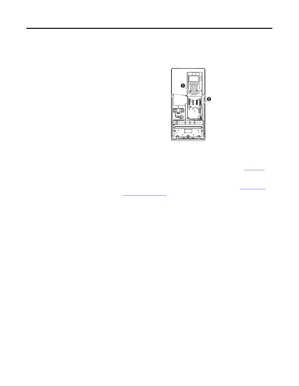
❏ 5. The remainder of this procedure requires that a Human Interface Module
(HIM) is connected to DPI Port 1 or 2.
Figure 1 - DPI Ports ➊ and ➋
❏ 6. Apply AC power and control voltages to the drive.
If any digital inputs are configured to Stop – CF, Run, or Enable, verify
that signals are present or the drive will not start. Refer to Chapter
6 for
a list of potential digital input conflicts.
If the STS LED is not flashing green at this point, refer to Drive Status
Indicators on page 18.
❏ 7. When prompted, select a display language. The Start-Up Screen will
automatically display for drives that have not been previously configured.
If the Start-Up screen is not displayed press the Enter key.
❏ 8. Press the Enter key to display the Start-Up Menu.
❏ 9. Use the Up/Down Arrow keys to highlight “2. Basic.”
❏ 10. Press the Enter key. Follow the menu using the Enter key which will step
you through the Start-Up routine.
The Start-Up routine asks simple questions and prompts you to input
required information.
16 Rockwell Automation Publication 750-PM001J-EN-P - October 2014
Page 17
Start Up Chapter 1
IMPORTANT
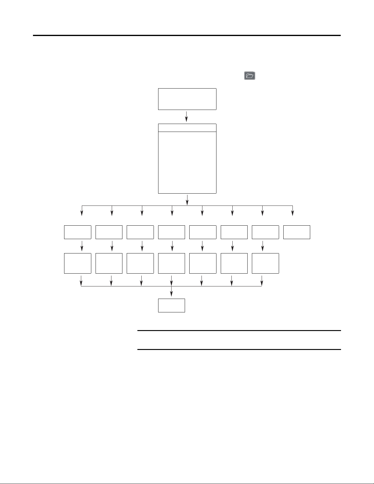
Start-Up Menu
Motor Control Motor Data Feedback Limits Tests Reference I/O Done
Motor Ctrl Motor Data Feedback
The Human Interface Module (HIM) displays the General Start-Up menu by
default upon initial power up of the drive. To navigate to the Start-Up menu after
the initial power up of the drive, press the (Folders) key.
General Startup
Start-Up Main Menu
Complete these steps in order:
Motor Control
Motor Data
Feedback
Limits
Tes t s
Ref, Ramp, Stop
I/O
Done
Confi g
Limits Tests Ref, Ramp,
Stop
I/O Return to
Main Menu
Motor Ctrl
Return
Motor Data
Return
Fdbk Cnfg
Return
Limits
Return
Return to
Main Menu
Tes t s
Return
Ref, Ramp,
Stop
Return
I/O
Return
If a start up routine is initiated, but must be terminated before the routine is
completed, be sure to press the Abort soft key to completely exit the routine.
Rockwell Automation Publication 750-PM001J-EN-P - October 2014 17
Page 18
Chapter 1 Start Up
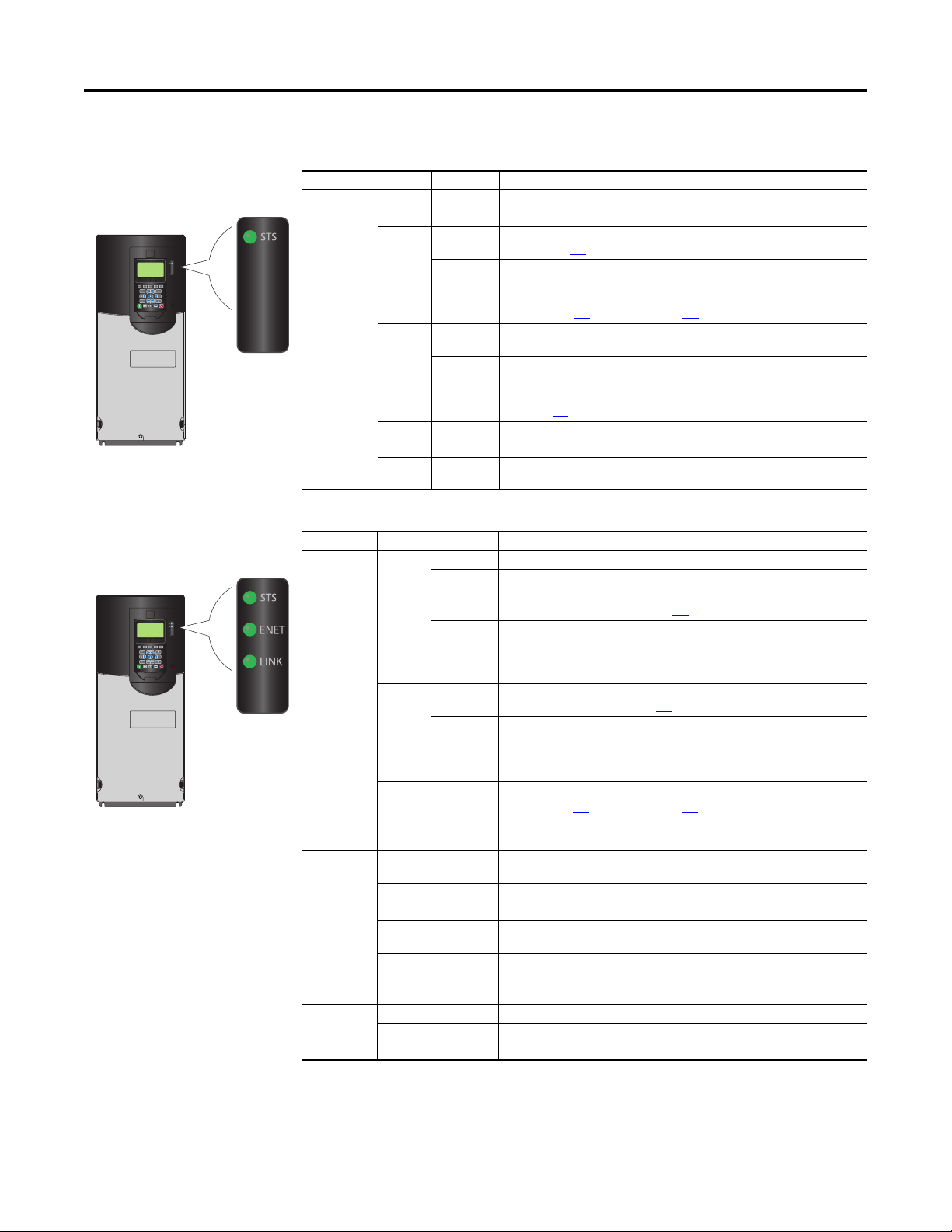
Drive Status Indicators
Table 1 - PowerFlex 753 Status Indicator Descriptions
Name Color State Description
STS
(Status)
Green Flashing Drive ready but not running, and no faults are present.
Steady Drive running, no faults are present.
Yellow Flashing Drive is not running, a start inhibit condition exists and the drive cannot be started.
Steady A t ype 1 (user configurable) alarm exists. If the drive is stopped, it is prevented from
Red Flashing A major fault has occurred. Drive will stop. Drive cannot be started until fault
Steady A non-resettable fault has occurred.
Red /
Yellow
Yellow /
Green
Green /
Red
Flashing
Alternately
Flashing
Alternately
Flashing
Alternately
See parameter 933
starting until the alarm condition is cleared. If the drive is running, it continues to
run but cannot restart until the alarm condition is cleared.
See parameters 959
condition is cleared. See parameter 951
A minor fault has occurred. When running, the drive continues to run. System is
brought to a stop under system control. Fault must be cleared to continue. Use
parameter 950
When running, a type 1 alarm exists.
See parameters 959
Drive is flash updating.
[Start Inhibits].
[Alarm Status A] and 960 [Alarm Status B].
[Last Fault Code].
[Minor Flt Cfg] to enable. If not enabled, acts like a major fault.
[Alarm Status A] and 960 [Alarm Status B].
Table 2 - PowerFlex 755 Status Indicator Descriptions
Name Color State Description
STS
(Status)
ENET Unlit Off Embedded EtherNet/IP is not properly connected to the network or needs an IP
LINK Unlit Off Adapter is not powered or is not transmitting on the network.
Green Flashing Drive ready but not running, and no faults are present.
Steady Drive running, no faults are present.
Yellow Flashing Drive is not running, a type 2 (non-configurable) alarm condition exists and the
Steady A type 1 (user configurable) alarm exists. If the drive is stopped, it is prevented from
Red Flashing A major fault has occurred. Drive will stop. Drive cannot be started until fault
Steady A non-resettable fault has occurred.
Red /
Yellow
Yellow /
Green
Green /
Red
Red Flashing An EtherNet/IP connection has timed out.
Red /
Green
Green Flashing Adapter is properly connected but is not communicating with any devices on the
Green Flashing Adapter is properly connected and transmitting data packets on the network.
Flashing
Alternately
Flashing
Alternately
Flashing
Alternately
Steady Adapter failed the duplicate IP address detection test.
Flashing
Alternately
Steady Adapter is properly connected and communicating on the network.
Steady Adapter is properly connected but is not transmitting on the network.
drive cannot be star ted. See parameter 961
starting until the alarm condition is cleared. If the drive is running, it continues to
run but cannot restart until the alarm condition is cleared.
See parameters 959 [Alar m Status A] and 960 [Alarm Stat us B].
condition is cleared. See parameter 951
A minor fault has occurred. When running, the drive continues to run. System is
brought to a stop under system control. Fault must be cleared to continue. Use
parameter 950 [Minor Flt Cfg] to enable. If not enabled, acts like a major fault.
When running, a type 1 alarm exists.
See parameters 959
Drive is flash updating.
address.
Adapter is performing a self-test.
network.
[Alarm Stat us A] and 960 [Alarm Status B].
[Type 2 Alarms].
[Last Fault Code].
18 Rockwell Automation Publication 750-PM001J-EN-P - October 2014
Page 19

Start Up Chapter 1
IMPORTANT
IMPORTANT
IMPORTANT
The Status Indicator LEDs on the HIM cradle do not indicate the current status of an
installed Communication Adapter option. If an optional Communication Adapter is
installed, refer to that option’s user manual for a description of LED location and
indication.
Establishing A Connection With EtherNet/IP
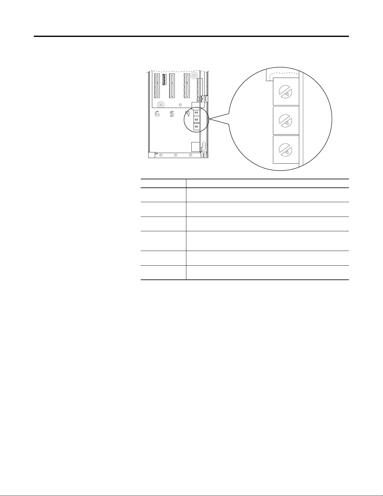
There are three methods for configuring the embedded EtherNet/IP adapter’s IP
address:
• Adapter Rotary Switches – Use the switches when working on a simple,
isolated network (for example, 192.168.1.xxx) that has other products
with switches to set their IP addresses, does not need to be accessed from
outside the network, and you prefer a simplified node addressing method.
The three adapter switches are read when the drive powers up, and
represent three decimal digits from top to bottom (see Figure 2
). If set to a
valid address (001-254), the adapter will use that value as the lower octet of
its IP address (192.168.1.xxx, where xxx = rotary switch settings), along
with a subnet mask of 255.255.255.0 and there will be no gateway
configured. Also, the setting for adapter P36 [BOOTP] is automatically
ignored.
See Figure 2
and its accompanying table for all possible switch settings and
their related descriptions.
When using the adapter rotary switches, set the IP address before power is applied
because the adapter uses the IP address it detects when it first receives power.
•BOOTP Server – Use BOOTP if you prefer to control the IP addresses of
devices using a server. The IP address, subnet mask, and gateway addresses
will then be provided by the BOOTP server.
•Adapter Parameters – Use adapter parameters when you want more
flexibility in setting up the IP address, or need to communicate outside the
control network using a gateway. The IP address, subnet mask, and
gateway addresses will then come from the adapter parameters you set.
Regardless of the method used to set the adapter’s IP address, each node on the
EtherNet/IP network must have a unique IP address. To change an IP address, you
must set the new value and then remove and reapply power to (or reset) the adapter.
Rockwell Automation Publication 750-PM001J-EN-P - October 2014 19
Page 20
Chapter 1 Start Up
Ones
Posi tion
Hundreds
Posi tion
Ten s Po si tio n
Figure 2 - Setting the IP Address Switches
5
6
4
7
3
8
2
9
1
0
5
6
4
7
3
8
2
9
1
0
5
6
4
7
3
8
2
9
1
0
Possible Settings Description
000 Adapter will use, depending on P36 [BOOTP], the BOOTP setting or the adapter parameter
001…254 Adapter will use the rotary switch settings for the IP address (192.168.1.xxx, where xxx =
255…887 Adapter will use, depending on P36 [BOOTP], the BOOTP setting or the adapter parameter
888 Resets the adapter IP address function to factory defaults. Thereafter, the drive must be
889…998 Adapter will use, depending on P36 [BOOTP], the BOOTP setting or the adapter parameter
999
(default settings)
settings for the IP address.
rotary switch settings).
settings for the IP address.
powered down, the switches set to a setting other than 888, and then the drive must be
powered up again to accept the new address.
settings for the IP address.
Disables the rotary switches. Adapter will use, depending on P36 [BOOTP], the BOOTP
setting or the adapter parameter settings for the IP address.
20 Rockwell Automation Publication 750-PM001J-EN-P - October 2014
Page 21

Chapter 2
Parameter Organization
This chapter lists and describes the PowerFlex 750-Series Port 0 drive parameters.
The parameters can be programmed (viewed/edited) using a Human Interface
Module (HIM). Refer to Enhanced PowerFlex 7-Class Human Interface Module
(HIM) User Manual, publication 20HIM-UM001
HIM to view and edit parameters. As an alternative, programming can also be
performed using DriveTools™ software and a personal computer.
Top ic Pag e
About Parameters 22
Parameter Access Level 23
How Drive Parameters are Organized 24
How Option Module Parameters are Organized 45
, for information on using the
Rockwell Automation Publication 750-PM001J-EN-P - October 2014 21
Page 22
Chapter 2 Paramete r Organ ization
753
Options
Reserved
Reserved
Reserved
Reserved
Reserved
Reserved
Reserved
Reserved
Reserved
Reserved
Reserved
Reserved
Reserved
Digital In 2
Digital In 1
Digital In 0
Default0000000000000000
Bit 1514131211109876543210
0 = Condition False
1 = Condition True
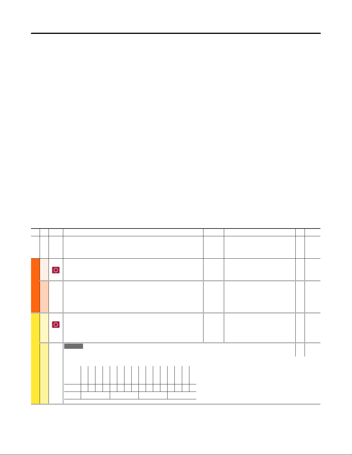
About Parameters
To configure a drive module to operate in a specific way, certain drive parameters
may have to be configured appropriately. Three types of parameters exist:
•Numeric Parameters
These parameters have a single numeric value (such as 1750.0 RPM).
•ENUM Parameters
These parameters allow a selection from 2 or more items. The LCD HIM
will display a text message for each item.
•Indirect Parameters
These parameters, represented by a maximum value of 159999 or
159999.15, are used to create assignments or to select either a data source
or destination. The first two digits are used to select a port. The next four
digits select a parameter number. If applicable, the two digits following the
decimal point select a bit. For example, to assign an I/O option module in
port 4 using a run contact on digital input 0, parameter 163 [DI Run] is set
to 040001.00.
•Bit Parameters
These parameters have individual bits associated with features or
conditions. If the bit is 0, the feature is off or the condition is false. If the
bit is 1, the feature is on or the condition is true.
The following table shows how each parameter type is presented in this manual.
Table 3 - Table Explan ation
➊➋ ➌
No. Display Name
Full Na me
Description
28 Motor NP RPM
Motor Nameplate Revolutions Per Minute
Motor Data
MOTOR CONTROL
Vector Regulator
Digin Functions
FEEDBACK & I/O
Digital Inputs
Rated RPM shown on the motor nameplate.
107 Trq Adapt En
Tor que Ad apt io n En ab le
Enables or disables the adaptive torque calculation. This selec tion is active only in motor
control mode flux vector induction (P35 [Motor Ctrl Mode] = 3 “Induction FV”).
164 DI Run Forward
Digital Input Run Forward
Assigns a digital input used to run the drive (2 wire control) and command forward
direction.
220 Digital In Sts
Digital Input Status
Status of the digital inputs resident on the main control board (Port 0).
Values
Units:
Default:
Min/Max:
Default:
Options:
Default:
Min/Max:
RPM
1750.0
1.0 / 40000.0
1 = “Enabled”
0 = “Disabled”
1 = “Enabled”
0.00
0.00 / 159999.15
Read-Write
Data Type
RW Real
RW 32-bit
Integer
RW 32-bit
Integer
RO 16-bit
Integer
22 Rockwell Automation Publication 750-PM001J-EN-P - October 2014
Page 23
Param eter Organizat ion Chapter 2
753
755
755 (8+)
No. Name
Description
➊ File and Group organization
No. - Parameter Number
Parameter value cannot be changed until the drive is stopped.
Parameter cannot be set to DataLink In.
➋ Name - Parameter name as it appears in the DriveExecutive software.
Description - Brief description of parameter function. The first line is the full text parameter name.
= Parameter or option is specific to PowerFlex 753 drives only.
= Parameter or option is specific to PowerFlex 755 drives only.
= Parameter or option is specific to PowerFlex 755 Frame 8 drives and larger only.
➌ Value s - Define the various operating characteristics of the parameter. There are 3 types of Values.
ENUM Default: Lists the value assigned at the factory.
Options: Displays the selections available.
Bit Default: Lists the value assigned at the factory.
Options: Displays the selections available.
Numeric Default Lists the value assigned at the factory.
Min/Max. Displays lowest possible setting/Displays highest possible setting.
Indicates if parameter is read-write or read-only.
RW = Read-Write
RO = Read Only
Indicates parameter data type (i.e. integer, floating point, boolean). 32-bit Integer
Read-Write Data Type
RW
RO
Parameter Access Level
Three parameter access level options are selectable by P301 [Access Level].
• Option 0 “Basic” is the most limited view that only displays commonly
utilized parameters and options.
• Option 1 “Advanced” is an expanded view that may be required to access
more advanced drive features.
• Option 2 “Expert” provides a comprehensive view of the drive’s entire
parameter set.
Rockwell Automation Publication 750-PM001J-EN-P - October 2014 23
Page 24

Chapter 2 Paramete r Organ ization
How Drive Parameters are Organized
DriveExecutive programming software displays parameters in “Linear List” or
“File Group Parameter” format. Viewing the parameters in “File Group
Parameter” format simplifies programming by grouping parameters that are used
for similar functions. There are eleven files. Each file is divided into multiple
groups of parameters.
Drive (Port 0) parameter descriptions begin on page 51
Basic Parameter View (Port 0)
Parameter 301 [Access Level] set to option 0 “Basic.”
File Group Parameters
Monitor Metering O utput Frequency 1
Monitor
Drive Data Rated Volts 20 Rated Amps 21 Rated kW 22
Motor Control Motor Data Motor NP Volts 25
Motor Control
Mtr Ctrl Options Motor Ctrl Mode 35 Maximum Voltage 36
Volt s per Hert z VHz Curv e 65
Autotune Autot une 70 Autotun e Torque 71 IPM_Lg_25_pc t 1630
Feedback & I/O Digin Functions Digital In Cfg 150
Feedback and IO
Control Board IO
Digital Inputs
753
Digital Outputs
753
Motor PTC
Analog Inputs
753
Analog Outputs
Commanded SpdRef 2
Mtr Vel Fdbk 3
Commanded Trq 4
Motor NP Amps 26
DI Enable 155
DI Clear Fault 156
DI Aux Fault 157
DI Stop 158
DI Cur Lmt Stop 159
DI Coast Stop 160
755
Digital In Sts 220
Digital In Sts 220 Dig In Filt Mask 222 Dig In Filt 223
753
Dig Out Sts 225
Dig Out Invert 226
PTC Cfg 250 PTC Status 251
Anlg In Type 255 Anlg In0 Value 260 Anlg In0 Hi 261 Anlg In0 Lo 262
753
Anlg Out Type 270 Anlg Out0 Sel 275 Anlg Out0 Data 277
Tor que C ur F dbk 5
Flux Cur Fdbk 6
Output Current 7
Output Voltage 8
Motor NP Hertz 27
Motor NP RPM 28
Maximum Freq 37
DI Start 161
DI Fwd Reverse 162
DI Run 163
DI Run Forward 164
DI Run Reverse 165
RO0 Sel 230
RO0 Level Sel 231
RO0 Level 232
RO0 Level CmpSts 233
.
Output Power 9
DC Bus Volts 11
Mtr NP Pwr Units 29
Motor NP Power 30
PWM Frequency 38 IPM Stc OfsTst K
IPM_Lg_50_pct 1631
IPM_Lg_75_pct 1632
IPM_Lg_100_pct 1633
IPM_Lg_125_pct 1634
DI Jog 1 166
DI Jog 1 Forward 167
DI Jog 1 Reverse 168
DI Jog 2 169
DI Jog 2 Forward 170
DI Jog 2 Reverse 171
TO0 S el 240
TO0 Leve l Sel 241
TO0 Leve l 242
TO0 Level CmpSts 243
Anlg Out0 DataHi 278
Anlg Out0 DataLo 279
Motor Poles 31
(1) Frames 1…7 Only
IPM_Ld_0_pct 1635
IPM_Ld_100_pct 1636
DI Manual Ctrl 172
DI Speed Sel 0 173
DI Speed Sel 1 174
DI Speed Sel 2 175
DI HOA Start 176
DI Accel 2 179
DI Decel 2 180
Anlg Out0 Hi 280
Anlg Out0 Lo 281
Anlg Out0 Val 282
(1)
1660
24 Rockwell Automation Publication 750-PM001J-EN-P - October 2014
Page 25

File Group Parameters
Drive Cfg Preferences Speed Units 300 Access Level 301 Language 302
Drive Cong
Control Cfg Voltage Class 305
SpdTrqPsn Mode A 309
Duty Rating 306
Direction Mode 308
Auto Manual Ctrl Logic Mask 324
Auto Mask 325
Manual Cmd Mask 326
Alt Man Ref Sel 328
Alt Man Ref AnHi 329
Alt Man Ref AnLo 330
Manual Preload 331
Manual Ref Mask 327
Braking Features Stop Mode A 370
Stop Mode B 371
Bus Reg Mode A 372
Bus Reg Mode B 373
Protection Motor Overload Motor OL Actn 410
Protection
Mtr OL at Pwr Up 411
DB Resistor Type 382
DB Ext Ohms 383
DB Ext Watts 384
DB ExtPulseWatts 385
Mtr OL Factor 413
Mtr OL Hertz 414
Stop Dwell Time 392
Dec Inhibit Actn 409
Mtr OL Reset Lvl 415
MtrOL Reset Time 416
Mtr OL Alarm Lvl 412
Load Limits Current Lmt Sel 421
Current Limit 1 422
Shear Pin Cfg 434
Shear Pin 1 Actn 435
Shear Pin1 Level 436
Shear Pin 1 Time 437
Power Loss Power Loss Actn 449 Pwr Loss Mode A 450
Speed Control Speed Limits Max Fwd Speed 520
Speed Control
Max Rev Speed 521
Speed Ramp Rates Accel Time 1 535
Accel Time 2 536
Speed Reference Spd Ref A Sel 545
Spd Ref A Stpt 546
Spd Ref A AnlgHi 547
Spd Ref A AnlgLo 548
Torque Control Torque Reference Trq Ref A Sel 675
Torq ue Con tro l
Trq Ref A Stpt 676
Trq Ref A AnlgHi 677
Trq Ref A AnlgLo 678
Trq Ref A Mult 679
Min Fwd Speed 522
Min Rev Speed 523
Decel Time 1 537
Decel Time 2 538
Spd Ref B Sel 550
Spd Ref B Stpt 551
Spd Ref B AnlgHi 552
Spd Ref B AnlgLo 553
Trq Ref B Se l 68 0
Trq Ref B Stpt 681
Trq Ref B An lgH i 682
Trq Ref B An lgL o 68 3
Trq Ref B Mult 684
Jog Acc Dec Time 539
Jog Speed 1 556
Jog Speed 2 557
MOP Init Select 566
MOP Init Stpt 567
Selected Trq Ref 685
Param eter Organizat ion Chapter 2
Preset Speed 1 571
Preset Speed 2 572
Preset Speed 3 573
Preset Speed 4 574
Preset Speed 5 575
Preset Speed 6 576
Preset Speed 7 577
Communication Comm Control Port 1 Reference 871
Communication
DPI Datalinks Data In A1 895
Data In A2 896
Data In B1 897
Data In B2 898
Diagnostics Status Speed Ref Source 930
Diagnostics
Last StartSource 931
Last Stop Source 932
Start Inhibits 933
Last StrtInhibit 934
Fault/Alarm Info Minor Flt Cfg 950
Last Fault Code 951
Fault Status A 952
Fault Status B 953
Rockwell Automation Publication 750-PM001J-EN-P - October 2014 25
Data In C1 899
Data In C2 900
Data In D1 901
Data In D2 902
Drive Status 1 935
Drive Status 2 936
Condition Sts 1 937
Data Out A1 905
Data Out A2 906
Data Out B1 907
Data Out B2 908
Data Out C1 909
Data Out C2 910
Data Out D1 911
Data Out D2 912
Page 26

Chapter 2 Paramete r Organ ization
Advanced Parameter View (Port 0)
Parameter 301 [Access Level] set to option 1 “Advanced.”
File Group Parameters
Monitor Metering O utput Frequency 1
Monitor
Drive Data R ated Volts 20 Rated Amps 21 Rated kW 22
Motor Control Motor Data Motor NP Volts 25
Motor Control
Mtr Ctrl Options Motor Ctrl Mode 35 Maximum Voltage 36
Volts per Hertz Start Acc Boost 60
Autotune Au totune 70
Feedback & I/O Digin Functions Digital In Cfg 150
Feedback and IO
Control Board IO
Digital Inputs
753
Digital Outputs
753
Motor PTC
Analog Inputs
753
Analog Outputs
R0 Predict Main
Commanded SpdRef 2
Mtr Vel Fdbk 3
Commanded Trq 4
Motor NP Amps 26
Run Boost 61
Autotune Torque 71
IR Voltage Drop 73
Ixo Voltage Drop 74
Flux Current Ref 75
DI Enable 155
DI Clear Fault 156
DI Aux Fault 157
DI Stop 158
DI Cur Lmt Stop 159
DI Coast Stop 160
DI Start 161
DI Fwd Reverse 162
DI Run 163
DI Run Forward 164
DI Run Reverse 165
755
Digital In Sts 220
Digital In Sts 220 Dig In Filt Mask 222 Dig In Filt 223
753
Dig Out Sts 225
Dig Out Invert 226
Dig Out Setpoint 227
PTC Cfg 250 PTC Status 251
Anlg In Type 255
Anlg In Sqrt 256
Anlg In Loss Sts 257
753
Anlg Out Type 270
Anlg Out Abs 271
753
RO PredMaint Sts 285
RO0 Load Type 286
Torque Cur Fdbk 5
Flux Cur Fdbk 6
Output Current 7
Output Voltage 8
Output Power 9
Output Powr Fctr 10
Motor NP Hertz 27
Motor NP RPM 28
Maximum Freq 37
PWM Frequency 38
Break Voltage 62
Break Frequency 63
Total Inertia 76
Inertia Test Lmt 77
DI Jog 1 166
DI Jog 1 Forward 167
DI Jog 1 Reverse 168
DI Jog 2 169
DI Jog 2 Forward 170
DI Jog 2 Reverse 171
DI Manual Ctrl 172
DI Speed Sel 0 173
DI Speed Sel 1 174
DI Speed Sel 2 175
DI HOA Start 176
DI MOP Inc 177
DI MOP Dec 178
RO0 Sel 230
RO0 Level Sel 231
RO0 Level 232
RO0 Level CmpSts 233
RO0 On Time 234
RO0 Off Time 235
Anlg In0 Value 260
Anlg In0 Hi 261
Anlg In0 Lo 262
Anlg Out0 Sel 275
Anlg Out0 Stpt 276
RO0 Load Amps 287
RO0 TotalLife 288
DC Bus Volts 11
DC Bus Memory 12
Elapsed MWH 13
Elapsed kWH 14
Elapsed Run Time 15
Mtr NP Pwr Units 29
Motor NP Power 30
Mtr Options Cfg 40
Flux Up Enable 43
Flux Up Time 44
VHz Curve 65
IPM_Lg_25_pct 1630
IPM_Lg_50_pct 1631
IPM_Lg_75_pct 1632
IPM_Lg_100_pct 1633
IPM_Lg_125_pct 1634
DI Accel 2 179
DI Decel 2 180
DI SpTqPs Sel 0 181
DI SpTqPs Sel 1 182
DI Stop Mode B 185
DI BusReg Mode B 186
DI PwrLoss ModeB 187
DI Pwr Loss 188
DI Precharge 189
DI Prchrg Seal 190
DI PID Enable 191
DI PID Hold 192
TO0 Sel 240
TO0 Level Sel 241
TO0 Level 242
TO0 Level CmpSts 243
TO0 On Time 244
TO0 Off Time 245
Anlg In0 LssActn 263
Anlg In0 Raw Val 264
Anlg Out0 Data 277
Anlg Out0 DataHi 278
Anlg Out0 DataLo 279
RO0 ElapsedLife 289
RO0 RemainLife 290
Elpsd Mtr MWHrs 16
Elpsd Rgn MWHrs 17
Elpsd Mtr kWHrs 18
Elpsd Rgn kWHrs 19
Motor Poles 31
(1)
IPM Stc OfsTst K
1660
(1) Frames 1…7 Only
IPM_Ld_0_pct 1635
IPM_Ld_100_pct 1636
DI PID Reset 193
DI PID Invert 194
DI Torque StptA 195
DI Fwd End Limit 196
DI Fwd Dec Limit 197
DI Rev End Limit 198
DI Rev Dec Limit 199
DI PHdwr OvrTrvl 200
DI NHdwr OvrTrvl 201
Anlg In0 Filt Gn 265
Anlg In0 Filt BW 266
Anlg Out0 Hi 280
Anlg Out0 Lo 281
Anlg Out0 Val 282
RO0 LifeEvntLvl 291
RO0 LifeEvntActn 292
26 Rockwell Automation Publication 750-PM001J-EN-P - October 2014
Page 27

File Group Parameters
Drive Cfg Preferences Speed Units 300 Access Level 301 Language 302
Drive Cong
Control Cfg Voltage Class 305
Duty Rating 306
Direction Mode 308
SpdTrqPsn Mode A 309
SpdTrqPsn Mode B 310
SpdTrqPsn Mode C 311
Actv SpTqPs Mode 313
SLAT Err Stpt 314
SLAT Dwell Time 315
SpdTrqPsn Mode D 312
Auto Manual Ctrl Logic Mask 324
Auto Mask 325
Manual Cmd Mask 326
Alt Man Ref Sel 328
Alt Man Ref AnHi 329
Alt Man Ref AnLo 330
Manual Preload 331
Manual Ref Mask 327
Drive Memory Reset Meters 336
Start Features Start At PowerUp 345
PowerUp Delay 346
Auto Retry Fault 347
Auto Rstrt Tries 348
Auto Rstrt Delay 349
Sleep Wake Mode 350
SleepWake RefSel 351
Sleep Level 352
Sleep Time 353
Wake Level 354
FlyingStart Mode 356
Wake Time 355
Braking Features Stop Mode A 370
Stop Mode B 371
Bus Reg Mode A 372
Bus Reg Mode B 373
Bus Reg Lvl Cfg 374
Bus Reg Level 375
Protection Motor Overload Motor OL Actn 410
Protection
Mtr OL at Pwr Up 411
DB Resistor Type 382
DB Ext Ohms 383
DB Ext Watts 384
DB ExtPulseWatts 385
Flux Braking En 388
Flux Braking Lmt 389
Mtr OL Factor 413
Mtr OL Hertz 414
Stop Dwell Time 392
DC Brake Lvl Sel 393
DC Brake Level 394
DC Brake Time 395
Mtr OL Reset Lvl 415
MtrOL Reset Time 416
Mtr OL Alarm Lvl 412
Load Limits Drive OL Mode 420
Current Lmt Sel 421
Current Limit 1 422
Current Limit 2 423
Active Cur Lmt 424
Current Rate Lmt 425
Regen Power Lmt 426
Power Loss Power Loss Actn 449 Pwr Loss Mode A 450
Motor Power Lmt 427 Shear Pin Cfg 434
Shear Pin 1 Actn 435
Shear Pin1 Level 436
Shear Pin 1 Time 437
Shear Pin 2 Actn 438
Shear Pin2 Level 439
Shear Pin 2 Time 440
Pwr Loss Mode B 453
Pwr Loss A Level 451
Pwr Loss A Time 452
Pwr Loss B Leve l 454
Pwr Loss B Time 455
Ground Fault Ground Warn Actn 466
Ground Warn Lvl 467
Predictive Main PredMaint Sts 469
PredMaintAmbTemp 470
PredMaint Rst En 471
PredMaint Reset 472
CbFan Derate
755 (8+)
CbFan TotalLife
CbFan ElpsdLife
CbFan RemainLife
CbFan EventLevel
CbFan EventActn
755 (8+)
755 (8+)
755 (8+)
755 (8+)
755 (8+)
481
482
483
484
485
486
HSFan Derate 488
HSFan TotalLife 489
HSFan ElpsdLife 490
HSFan RemainLife 491
HSFan EventLevel 492
HSFan EventActn 493
HSFan ResetLog
(1)
InFan Derate 495
InFan TotalLife 496
InFan ElpsdLife 497
MtrBrngTotalLife 502
MtrBrngElpsdLife 503
MtrBrngRemainLif 504
MtrBrngEventLvl 505
MtrBrngEventActn 506
MtrBrng ResetLog 507
494
MtrLubeElpsdHrs 508
MtrLubeEventLvl 509
MtrLubeEventActn 510
InFan RemainLife 498
InFan EventLevel 499
InFan EventActn 500
InFan ResetLog 501
(1) 755 Frames 1…7 only.
Param eter Organizat ion Chapter 2
Prchrg Control 321
Prchrg Delay 322
Prchrg Err Cfg 323
Brake Off Adj 1 402
Brake Off Adj 2 403
Dec Inhibit Actn 409
Mtr OL Counts 418
Mtr OL Trip Time 419
Load Loss Action 441
Load Loss Level 442
Load Loss Time 443
OutPhaseLossActn 444
Out PhaseLossLvl 445
UnderVltg Action 460
UnderVltg Level 461
InPhase LossActn 462
InPhase Loss Lvl 463
DC Bus Mem Reset 464
MchBrngTotalLife 511
MchBrngElpsdLife 512
MchBrngRemainLif 513
MchBrngEventLvl 514
MchBrngEventActn 515
MchBrngResetLog 516
MchLubeElpsdHrs 517
MchLube EventLvl 518
MchLubeEventActn 519
Rockwell Automation Publication 750-PM001J-EN-P - October 2014 27
Page 28

Chapter 2 Paramete r Organ ization
File Group Parameters
Speed Control Speed Limits Max Fwd Speed 520
Speed Control
Max Rev Speed 521
Speed Ramp Rates Accel Time 1 535
Accel Time 2 536
Speed Reference Spd Ref A Sel 545
Spd Ref A Stpt 546
Spd Ref A AnlgHi 547
Spd Ref A AnlgLo 548
Spd Ref A Mult 549
Spd Ref B Sel 550
Spd Ref B Stpt 551
Spd Ref B AnlgHi 552
Spd Ref B AnlgLo 553
Spd Ref B Mult 554
Sp eed Trim Tr im R ef A Sel 6 00
Trim Ref A Stpt 601
Trim RefA AnlgHi 602
Trim RefA AnlgLo 603
Slip/Droop Comp Droop RPM at FLA 620
Slip RPM at FLA 621
Slip Comp BW 622
Speed Regulator Spd Options Ctrl 635
Speed Reg BW 636
Filtered SpdFdbk 640
Speed Error 641
Speed Comp Speed Comp Sel 665
Speed Comp Gain 666
Speed Comp Out 667
Torque Control Torq ue Li mit s Pos Torqu e Lim it 670
Torq ue Con tro l
Neg Torque Limit 671
Torque Reference Trq Ref A Sel 675
Trq Ref A Stpt 676
Trq Ref A AnlgHi 677
Trq Ref A AnlgLo 678
Trq Ref A Mult 679
Inertia Comp
755
Inertia Adaption
Inertia CompMode 695 Inertia Acc Gain 696
755
InAdp LdObs Mode 704
Inertia Adapt BW 705
InertiaAdaptGain 706
Frictio n Comp
755
FrctnComp Mode 1560
FrctnComp Trig 1561
Min Fwd Speed 522
Min Rev Speed 523
Decel Time 1 537
Decel Time 2 538
Spd Ref Scale 555
Jog Speed 1 556
Jog Speed 2 557
MOP Reference 558
Save MOP Ref 559
MOP Rate 560
MOP High Limit 561
MOP Low Limit 562
MOP Init Select 566
MOP Init Stpt 567
Trim Ref B Sel 604
Trim Ref B Stpt 605
Trim RefB AnlgHi 606
Trim RefB AnlgLo 607
Speed Reg Kp 645
Speed Reg Max Kp 646
Speed Reg Ki 647
Trq Ref B Sel 680
Trq Ref B Stpt 681
Trq Ref B AnlgHi 682
Trq Ref B AnlgLo 683
Trq Ref B Mult 684
Inertia Dec Gain 697
Load Estimate 707
InertiaTrqAdd 708
FrctnComp Hyst 1562
FrctnComp Time 1563
Overspeed Limit 524
Zero Speed Limit 525
Skip Speed 1 526
Skip Speed 2 527
Skip Speed 3 528
Skip Speed Band 529
Jog Acc Dec Time 539 S Curve Accel 540
S Curve Decel 541
DI ManRef Sel 563
DI ManRef AnlgHi 564
DI ManRef AnlgLo 565
Preset Speed 1 571
Preset Speed 2 572
Preset Speed 3 573
Preset Speed 4 574
Preset Speed 5 575
Preset Speed 6 576
Preset Speed 7 577
TrmPct RefA Sel 608
TrmPct RefA Stpt 609
TrmPct RefA AnHi 610
TrmPct RefA AnLo 611
Spd Loop Damping 653
Spd Reg Int Out 654
TrmPct RefB Sel 612
TrmPct RefB Stpt 613
TrmPct RefB AnHi 614
TrmPct RefB AnLo 615
VHzSV Spd Reg Kp 663
VHzSV Spd Reg Ki 664
Spd Reg Pos Lmt 655
Spd Reg Neg Lmt 656
SReg Output 660
Selected Trq Ref 685 Torque Step 686
Filtered Trq Ref 689
Limited Trq Ref 690
Inert Comp LPFBW 698
Ext Ramped Ref 700
Inertia Comp Out 699
IA LdObs Delay 709
Load Observer BW 711
InertAdptFltrBW 710
FrctnComp Stick 1564
FrctnComp Slip 1565
FrctnComp Rated 1566
FrctnComp Out 1567
28 Rockwell Automation Publication 750-PM001J-EN-P - October 2014
Page 29

File Group Parameters
Posit ion Cont rol Position Cfg/Sts PTP PsnRefStatus 720
Position Control
Position Control 721
Position Homing Homing Status 730
Homing Control 731
755
Position Watch
PsnWatch1 Select 745
PsnWatch1 DtctIn 746
PsnWatch1 Stpt 747
Interpolator
755
Interp Control 755 Interp Psn Input 756
Direct Psn Ref Select 765 Psn Direct Stpt 766
Point to Point PTP Control 770
PTP Mode 771
DI Indx Step 772
DI Indx StepRev 773
DI Indx StepPrst 774
755
Phase Lock Loop
PLL Control 795
PLL Ext Spd Sel 796
PLL Ext Spd Stpt 797
PLL Ext SpdScale 798
Electronic Gear Psn Ref EGR Out 815 Psn EGR Mult 816
Position Offset Psn Offset 1 Sel 820
Psn Offset 1 821
Ld Psn Fdbk Scal
755
LdPsn Fdbk Mult 825 LdPsn Fdbk Div 826
Position Reg Psn Error 835
Communication Comm Control Port 1 Reference 871
Communication
Port 2 Reference 872
Port 3 Reference 873
Security Port Mask Act 885
Logic Mask Act 886
DPI Datalinks Data In A1 895
Data In A2 896
Data In B1 897
Data In B2 898
Owners Stop Owner 919
Start Owner 920
Psn Selected Ref 722
Psn Command 723
DI Find Home 732
DI Redefine Psn 733
DI OL Home Limit 734
PsnWatch2 Select 748
PsnWatch2 DtctIn 749
PsnWatch2 Stpt 750
Interp Vel Input 757
Interp Trq Input 758
Psn Direct Ref 767
PTP Ref Sel 775
PTP Reference 776
PTP Feedback 777
PTP Ref Scale 778
PTP Index Preset 779
PLL Psn Ref Sel 799
PLL Psn Stpt 800
PLL BW 801
PLL LPFilter BW 802
PLL Virt Enc RPM 803
Psn EGR Div 817
Psn Offset 2 Sel 822
Psn Offset 2 823
Psn Actual 836
Psn Load Actual
755
837
Psn Reg Ki 838
Psn Reg Kp 839
Port 4 Reference 874
Port 5 Reference 875
Port 6 Reference 876
Write Mask Act 887
Write Mask Cfg 888
Data In C1 899
Data In C2 900
Data In D1 901
Data In D2 902
Jog Owner 921
Dir Owner 922
Param eter Organizat ion Chapter 2
Psn Reg Status 724
Zero Position 725
Find Home Speed 735
Find Home Ramp 736
Interp Psn Out 759
Interp Vel Out 760
Interp Trq Out 761
PTP Setpoint 780
PTP Accel Time 781
PTP Decel Time 782
PTP Speed FwdRef 783
PTP Command 784
PLL EPR Input 804
PLL Rvls Input 805
PLL Psn Out Fltr 806
PLL Speed Out 807
PLL Speed OutAdv 808
Psn Offset Vel 824
PReg Pos Int Lmt 840
PReg Neg Int Lmt 841
PsnReg IntgrlOut 842
PsnReg Spd Out 843
Port13 Reference
755
877
Port14 Reference 878
Data Out A1 905
Data Out A2 906
Data Out B1 907
Data Out B2 908
Clear Flt Owner 923
Manual Owner 924
In Pos Psn Band 726
In Pos Psn Dwell 727
Actual Home Psn 737
User Home Psn 738
PTP Fwd Vel Lmt 785
PTP Rev Vel Lmt 786
PTP S Curve 787
PTP Vel Override 788
PTP EGR Mult 789
PTP EGR Div 790
PLL Enc Out 809
PLL Enc Out Adv 810
PLL EPR Output 811
PLL Rvls Output 812
PReg Pos Spd Lmt 844
PReg Neg Spd Lmt 845
Psn Reg Droop 846
Psn Fdbk 847
Psn Gear Ratio 848
Drive Logic Rslt 879
DPI Ref Rslt 880
DPI Ramp Rslt 881
DPI Logic Rslt 882
Drive Ref Rslt 883
Drive Ramp Rslt 884
Data Out C1 909
Data Out C2 910
Data Out D1 911
Data Out D2 912
Ref Select Owner 925
Rockwell Automation Publication 750-PM001J-EN-P - October 2014 29
Page 30

Chapter 2 Paramete r Organ ization
File Group Parameters
Diagnostics Status Speed Ref Source 930
Diagnostics
Last StartSource 931
Last Stop Source 932
Start Inhibits 933
Last StrtInhibit 934
Fault/Alarm Info Minor Flt Cfg 950
Last Fault Code 951
Fault Status A 952
Fault Status B 953
755
Peak Detection
PkDtct Stpt Real 1035
PkDtct Stpt DInt 1036
PkDtct1 In Sel 1037
Applications Process PID PID Cfg 1065
Applications
PID Control 1066
PID Ref Sel 1067
PID Ref AnlgHi 1068
PID Ref AnlgLo 1069
PID Setpoint 1070
PID Ref Mult 1071
Tor que Pro ve
755
Trq Prove Cfg 1100
Trq Prove Setup 1101
DI FloatMicroPsn 1102
Trq Prove Status 1103
Fibers Function Fiber Control 1120
Fiber Status 1121
Sync Time 1122
Adjustable Vltg Adj Vltg Config 1131
Adj Vltg Selec t 1133
Adj Vltg Ref Hi 1134
Adj Vltg Ref Lo 1135
Pump Jack Rod Speed 1165
Rod Torque 1166
Rod Speed Cmd 1167
Pump Off Pump Off Config 1187
Pump Off Setup 1188
Pump Off Action 1189
Pump Off Control 1190
Pump Off Status 1191
Drive Status 1 935
Drive Status 2 936
Condition Sts 1 937
Drive OL Count 940
Status1 at Fault 954
Status2 at Fault 955
Fault Frequency 956
Fault Amps 957
Fault Bus Volts 958
PkDtct1PresetSel 1038
Peak1 Cfg 1039
Peak 1 Change 1040
PID Fdbk Sel 1072
PID Fdbk AnlgHi 1073
PID Fdbk AnlgLo 1074
PID FBLoss SpSel 1075
PID FBLoss TqSel 1076
PID Fdbk 1077
PID Fdbk Mult 1078
Trq Lmt SlewRate 1104
Speed Dev Band 1105
SpdBand Intgrtr 1106
Traverse Inc 1123
Traverse Dec 1124
Max Traverse 1125
Adj Vltg TrimSel 1136
Adj Vltg Trim Hi 1137
Adj Vltg Trim Lo 1138
Adj Vltg Command 1139
Adj Vltg AccTime 1140
Adj Vltg DecTime 1141
TorqAlarm Action 1168
TorqAlarm Config 1169
TorqAlarm Dwell 1170
TorqAlarm Level 1171
TorqAlm Timeout 1172
TorqAlarm TOActn 1173
Pump Cycle Store 1192
Set Top ofStroke 1193
Torque Setpoint 1194
Pump Off Level 1195
Pump Off Speed 1196
Pump Off Time 1197
IGBT Temp Pct 941
IGBT Temp C 942
At Limit Status 945
Safety Port Sts 946
Drive Temp Pct 943
Drive Temp C 944
Alarm Status A 959
Alarm Status B 960
AlarmA at Fault 962
AlarmB at Fault 963
Type 2 Alarms 961
PeakDetect1 Out 1041
PkDtct2 In Sel 1042
PkDtct2PresetSel 1043
PID Output Sel 1079
PID Output Mult 1080
PID Upper Limit 1081
PID Lower Limit 1082
PID Deadband 1083
PID LP Filter BW 1084
PID Preload 1085
Peak2 Cfg 1044
Peak 2 Change 1045
PeakDetect2 Out 1046
PID Prop Gain 1086
PID Int Time 1087
PID Deriv Time 1088
PID Status 1089
PID Ref Meter 1090
PID Fdbk Meter 1091
PID Error Meter 1092
PID Output Meter 1093
Brk Release Time 1107
Brk Set Time 1108
Brk Alarm Travel 1109
Brk Slip Count 1110
Float Tolerance 1111
MicroPsnScalePct 1112
ZeroSpdFloatTime 1113
755
Br ake Test To rq
1114
P Jump 1126 DI Fiber SyncEna 1129
DI Fiber TravDis 1130
Adj Vltg Preset1 1142
Adj Vltg Preset2 1143
Adj Vltg Preset3 1144
Adj Vltg Preset4 1145
Adj Vltg Preset5 1146
Adj Vltg Preset6 1147
Adj Vltg RefMult 1149
Adj Vltg Scurve 1150
Adj Vltg TrimPct 1151
Min Adj Voltage 1152
Dead Time Comp 1153
DC Offset Ctrl 1154
Adj Vltg Preset7 1148
Total Gear Ratio 1174
Max Rod Speed 1175
Max Rod Torque 1176
Min Rod Speed 1177
Motor Sheave 1178
PCP Pump Sheave 1180
Gearbox Limit 1181
Gearbox Rating 1182
Gearbox Ratio 1183
Gearbox Sheave 1184
OilWell Pump Cfg 1179
Pct Cycle Torque 1198
Pct Lift Torque 1199
Pct Drop Torque 1200
Stroke Pos Count 1201
Stroke Per Min 1202
Pump Off Count 1203
PumpOff SleepCnt 1204
Day Stroke Count 1205
DI PumpOff Disbl 1206
Pump OffSleepLvl 1207
30 Rockwell Automation Publication 750-PM001J-EN-P - October 2014
Page 31

File Group Parameters
Applications Profiling
Applications
755
Profile Status 1210
Units Traveled 1212
Profile Command 1213
Counts Per Unit 1215
ProfVel Override 1216
Prof DI Invert 1217
DI Hold Step 1218
DI Abort Step 1219
DI Abort Profile 1220
Camming
755
PCAM Control 1390
PCAM Mode 1391
PCAM Psn Select 1392
PCAM Psn Stpt 1393
PCAM Psn Ofst 1394
PCAM PsnOfst Eps 1395
Roll Position
755
Roll Psn Config 1500
Roll Psn Status 1501
RP Psn Fdbk Stpt 1502
RP Psn Fdbk Sel 1503
Tor que Bo ost
755
PsnTrqBst Ctrl 1515
PsnTrqBst Sts 1516
PsnTrqBst RefSel 1517
PsnTrqBstPsnOfst 1518
PsnTrqBst UNWCnt 1519
Variable Boost VB Config 1535
VB Status 1536
VB Voltage 1537
VB Time 1538
755
Spindle Orient
SO Config 1580
SO Status 1581
SO Setpoint 1582
SO Offset 1583
Id Compensation
755
Id Comp Enbl 1600
Id Comp Mtrng 1 1601
IdCompMtrng 1 Iq 1602
Id Comp Mtrng 2 1603
IdCompMtrng 2 Iq 1604
Id Comp Mtrng 3 1605
IdCompMtrng 3 Iq 1606
DI Vel Override 1221
DI StrtStep Sel0 1222
DI StrtStep Sel1 1223
DI StrtStep Sel2 1224
DI StrtStep Sel3 1225
DI StrtStep Sel4 1226
PCAM Span X 1396
PCAM Scale X 1397
PCAM Span Y 1398
PCAM ScaleY Sel 1399
PCAM ScaleYSetPt 1400
PCAM VelScaleSel 1401
PCAM VelScaleSP 1402
PCAM Slope Begin 1403
PCAM Slope End 1404
PCAM Main EndPnt 1405
PCAM Main Types 1406
Roll Psn Preset 1504
Roll Psn Offset 1505
RP EPR Input 1506
PsnTrqBst Ps X1 1520
PsnTrqBst Ps X2 1521
PsnTrqBst Ps X3 1522
PsnTrqBst Ps X4 1523
PsnTrqBst Ps X5 1524
VB Minimum 1539
VB Maximum 1540
VB Accel Rate 1541
VB Decel Rate 1542
SO EPR Input 1584
SO Rvls Input 1585
SO Rvls Output 1586
SO Cnts per Rvls 1587
Id Comp Mtrng 4 1607
IdCompMtrng 4 Iq 1608
Id Comp Mtrng 5 1609
IdCompMtrng 5 Iq 1610
Id Comp Mtrng 6 1611
IdCompMtrng 6 Iq 1612
Param eter Organizat ion Chapter 2
Step 1, 2, 3…16 Type 1230, 1240, 1250…1380
Step 1, 2, 3…16 Velocity 1231, 1241, 1251…1381
Step 1, 2, 3…16 Accel 1232, 1242, 1252…1382
Step 1, 2, 3…16 Decel 1233, 1243, 1253…1383
Step 1, 2, 3…16 Value 1234, 1244, 1254…1384
Step 1, 2, 3…16 Dwell 1235, 1245, 1255…1385
Step 1, 2, 3…16 Batch 1236, 1246, 1256…1386
Step 1, 2, 3…16 Next 1237, 1247, 1257…1387
Step 1, 2, 3…16 Action 1238, 1248, 1258…1388
Step 1, 2, 3…16 Dig In 1239, 1249, 1259…1389
PCAM Main Pt X 0, 1, 2…15 1407, 1409, 1411…1437
PCAM Main Pt Y 0, 1, 2…15 1408, 1410, 1412…1438
PCAM Aux EndPnt 1439
PCAM Aux Types 1440
PCAM Aux Pt X 1, 2, 3…15 1441, 1443, 1445…1469
PCAM Aux Pt Y 1, 2, 3…15 1442, 1444, 1446…1470
PCAM Status 1471
PCAM Vel Out 1472
PCAM Psn Out 1473
DI PCAM Start 1474
RP Rvls Input 1507
RP Rvls Output 1508
RP Unwind 1509
PsnTrqBst Trq Y2 1525
RP Unit Scale 1510
RP Psn Output 1511
RP Unit Out 1512
PsnTrqBst TrqOut 1528
PsnTrqBst Trq Y3 1526
PsnTrqBst Trq Y4 1527
VB Frequency 1543
VB Min Freq 1544
VB Flux Thresh 1545
VB Flux Lag Freq 154 6
VB Current Rate 1548
VB Current Hyst 1549
VB Cur Thresh 1550
VB Rate Lag Freq 1551
VB Filt Flux Cur 1547
SO Unit Scale 1588
SO Position Out 1589
SO Unit Out 1590
SO Accel Time 1591
SO Decel Time 1592
SO Fwd Vel Lmt 1593
SO Rev Vel Lmt 1594
Id Comp Regen 1 1613
IdCompRegen 1 Iq 1614
Id Comp Regen 2 1615
IdCompRegen 2 Iq 1616
Id Comp Regen 3 1617
IdCompRegen 3 Iq 1618
Id Comp Regen 4 1619
IdCompRegen 4 Iq 1620
Id Comp Regen 5 1621
IdCompRegen 5 Iq 1622
Id Comp Regen 6 1623
IdCompRegen 6 Iq 1624
Rockwell Automation Publication 750-PM001J-EN-P - October 2014 31
Page 32

Chapter 2 Paramete r Organ ization
Expert Parameter View (Port 0)
Parameter 301 [Access Level] set to option 2 “Expert.”
File Group Parameters
Monitor Metering O utput Frequency 1
Monitor
Drive Data R ated Volts 20 Rated Amps 21 Rated kW 22
Motor Control Motor Data Motor NP Volts 25
Motor Control
Mtr Ctrl Options Motor Ctrl Mode 35
Commanded SpdRef 2
Mtr Vel Fdbk 3
Commanded Trq 4
Motor NP Amps 26
Maximum Voltage 36
Maximum Freq 37
PWM Frequency 38
Mtr Options Cfg 40
Torque Cur Fdbk 5
Flux Cur Fdbk 6
Output Current 7
Output Voltage 8
Motor NP Hertz 27
Motor NP RPM 28
Bus Utilization 42
Flux Up Enable 43
Flux Up Time 44
Flux Down Ki 4 5
Flux Down Kp 4 6
Output Power 9
Output Powr Fctr 10
DC Bus Volts 11
DC Bus Memory 12
Mtr NP Pwr Units 29
Motor NP Power 30
Econ At Ref Ki 47
Econ AccD ec Ki 48
Econ AccD ec Kp 49
Stability Filter 50
Stab Volt Gain 51
Stab Angle Gain 52
Elapsed MWH 13
Elapsed kWH 14
Elapsed Run Time 15
Elpsd Mtr MWHrs 16
Elpsd Rgn MWHrs 17
Elpsd Mtr kWHrs 18
Elpsd Rgn kWHrs 19
Motor Poles 31
IPM V FB HP Filt 1648
IPM SpdEst Filt 1649
IPM SpdEst Kp 1650
IPM SpdEst Ki 1651
IPM SpdEst KiAdj 1652
IPM Tran PWM 1653
IPMTran PWM Hyst 1654
IPM Tran Mode 1655
IPM TranMod Hyst 1656
IPM Tran Filt Lo 1657
IPM Tran Filt Hi 1658
IPM Tran Angle 1659
IPM Stc OfsTst K 1660
IPM Lq Cmd BW 1661
Volts per Hertz Start Acc Boost 60
Run Boost 61
Autotune Au totune 70
Autotune Torque 71
IR Voltage Drop 73
Ixo Voltage Drop 74
Flux Current Ref 75
Vector Regulator VCL Cur Reg BW 95
VCL Cur Reg Kp 96
VCL Cur Reg Ki 97
VEncdls FReg Kp 98
VEncdls FReg Ki 99
Slip Reg Enable 100
Slip Reg Ki 101
Slip Reg Kp 102
Break Voltage 62
Break Frequency 63
Total Inertia 76
Inertia Test Lmt 77
Encdrlss AngComp 78
Encdrlss VltComp 79
PM Cfg 80
PM PriEnc Offset 81
PM AltEnc Offset 82
PM OfstTst Cur 83
PM OfstTst CRamp 84
Flux Reg Enable 103
Flux Reg Ki 104
Flux Reg Kp 105
Trq Adapt Speed 106
Trq Adapt En 107
Phase Delay Comp 108
Trq Comp Mode 109
Trq Comp Mtring 110
SVC Boost Filter 64
VHz Curve 65
PM OfstTst FRamp 85
PM CEMF Voltage 86
PM IR Voltage 87
PM IXq Voltage
PM IXd Voltage
755
755
PM Vqs Reg Kp 91
PM Vqs Reg Ki 92
PM Dir Test Cur 93
PM IXqVoltage125 120
Trq Comp Regen 111
Slip Adapt Iqs 112
SFAdapt SlewLmt 113
SFAdapt SlewRate 11 4
SFAdapt CnvrgLvl 115
SFAdapt CnvrgLmt 116
Parameters 1648…1661 used
by drive frames 1…7 only.
IPM_Lg_25_pct 1630
IPM_Lg_50_pct 1631
IPM_Lg_75_pct 1632
88
IPM_Lg_100_pct 1633
89
IPM_Lg_125_pct 1634
IPM_Ld_0_pct 1635
IPM_Ld_100_pct 1636
IPM PriOffstComp 1646
IPM AltOffstComp 1647
IPM Bus Prot
755
IPMVqFFwdCemf
IPMVqFFwdLdIdWe
IPMVdFFwdLqIqWe
IPM Max Cur
IPM Max Spd
IPM TrqTrim Kp
IPM TrqTrim Ki
755
755
755
755
IPM TrqTrim HLim
IPM TrqTrim LLim
1629
755
1637
755
1638
755
1639
1640
1641
1642
1643
755
1644
755
1645
32 Rockwell Automation Publication 750-PM001J-EN-P - October 2014
Page 33

File Group Parameters
Feedback & I/O Feedback Pri Vel Fdbk Sel 125
Feedback and IO
Pri Vel FdbkFltr 126
Pri Vel Feedback 127
Alt Vel Fdbk Sel 128
Alt Vel FdbkFltr 129
Digin Functions Digital In Cfg 150
DI Enable 155
DI Clear Fault 156
DI Aux Fault 157
DI Stop 158
DI Cur Lmt Stop 159
DI Coast Stop 160
DI Start 161
DI Fwd Reverse 162
DI Run 163
DI Run Forward 164
DI Run Reverse 165
755
Control Board IO
Digital Inputs
Digital Outputs
753
Digital In Sts 220
Digital In Sts 220 Dig In Filt Mask 222 Dig In Filt 223
753
Dig Out Sts 225
Dig Out Invert 226
Dig Out Setpoint 227
753
Motor PTC
Analog Inputs
753
PTC Cfg 250 PTC Sts 251
Anlg In Type 255
Anlg In Sqrt 256
Anlg In Loss Sts 257
Analog Outputs
753
Anlg Out Type 270
Anlg Out Abs 271
753
R0 Predict Main
RO PredMaint Sts 285
RO0 Load Type 286
Alt Vel Feedback 130
Active Vel Fdbk 131
Aux Vel Fdbk Sel 132
Aux Vel FdbkFltr 133
Aux Vel Feedback 134
DI Jog 1 166
DI Jog 1 Forward 167
DI Jog 1 Reverse 168
DI Jog 2 169
DI Jog 2 Forward 170
DI Jog 2 Reverse 171
DI Manual Ctrl 172
DI Speed Sel 0 173
DI Speed Sel 1 174
DI Speed Sel 2 175
DI HOA Start 176
DI MOP Inc 177
DI MOP Dec 178
RO0 Sel 230
RO0 Level Sel 231
RO0 Level 232
RO0 Level CmpSts 233
RO0 On Time 234
RO0 Off Time 235
Anlg In0 Value 260
Anlg In0 Hi 261
Anlg In0 Lo 262
Anlg Out0 Sel 275
Anlg Out0 Stpt 276
RO0 Load Amps 287
RO0 TotalLife 288
Param eter Organizat ion Chapter 2
Psn Fdbk Sel 135
755
Load Psn FdbkSel
136
Open Loop Fdbk 137
Simulator Fdbk 138
DI Accel 2 179
DI Decel 2 180
DI SpTqPs Sel 0 181
DI SpTqPs Sel 1 182
DI Stop Mode B 185
DI BusReg Mode B 186
DI PwrLoss ModeB 187
DI Pwr Loss 188
DI Precharge 189
DI Prchrg Seal 190
DI PID Enable 191
DI PID Hold 192
TO0 Sel 240
TO0 Level Sel 241
TO0 Level 242
TO0 Level CmpSts 243
TO0 On Time 244
TO0 Off Time 245
Anlg In0 LssActn 263
Anlg In0 Raw Val 264
Anlg Out0 Data 277
Anlg Out0 DataHi 278
Anlg Out0 DataLo 279
RO0 ElapsedLife 289
RO0 RemainLife 290
Delayed Spd Ref
Virt ual EncD elay
Virtual Enc EPR
Virt ual Enc Ps n
755
139
755
755
755
140
141
142
DI PID Reset 193
DI PID Invert 194
DI Torque StptA 195
DI Fwd End Limit 196
DI Fwd Dec Limit 197
DI Rev End Limit 198
DI Rev Dec Limit 199
DI PHdwr OvrTrvl 200
DI NHdwr OvrTrvl 201
Anlg In0 Filt Gn 265
Anlg In0 Filt BW 266
Anlg Out0 Hi 280
Anlg Out0 Lo 281
Anlg Out0 Val 282
RO0 LifeEvntLvl 291
RO0 LifeEvntActn 292
Rockwell Automation Publication 750-PM001J-EN-P - October 2014 33
Page 34

Chapter 2 Paramete r Organ ization
File Group Parameters
Drive Cfg Preferences Speed Units 300 Access Level 301 Language 302
Drive Cong
Control Cfg Voltage Class 305
Duty Rating 306
Direction Mode 308
SpdTrqPsn Mode A 309
SpdTrqPsn Mode B 310
SpdTrqPsn Mode C 311
Actv SpTqPs Mode 313
SLAT Err Stpt 314
SLAT Dwell Time 315
SpdTrqPsn Mode D 312
Auto Manual Ctrl Logic Mask 324
Auto Mask 325
Manual Cmd Mask 326
Manual Ref Mask 327
Alt Man Ref Sel 328
Alt Man Ref AnHi 329
Alt Man Ref AnLo 330
Drive Memory Reset Meters 336
Start Features Start At PowerUp 345
PowerUp Delay 346
Auto Retry Fault 347
Auto Rstrt Tries 348
Auto Rstrt Delay 349
Sleep Wake Mode 350
SleepWake RefSel 351
Sleep Level 352
Sleep Time 353
Wake Level 354
FlyingStart Mode 356
FS Gain 357
FS Ki 358
FS Speed Reg Ki 359
FS Speed Reg Kp 360
Wake Time 355
Braking Features Stop Mode A 370
Stop Mode B 371
Bus Reg Mode A 372
Bus Reg Mode B 373
Bus Reg Lvl Cfg 374
Bus Reg Level 375
Bus Limit Kp 376
Bus Limit Kd 377
Protection Motor Overload Motor OL Actn 410
Protection
Mtr OL at Pwr Up 411
Bus Limit ACR Ki 378
Bus Limit ACR Kp 379
Bus Reg Ki 380
Bus Reg Kp 381
DB Resistor Type 382
DB Ext Ohms 383
DB Ext Watts 384
DB ExtPulseWatts 385
Mtr OL Factor 413
Mtr OL Hertz 414
Flux Braking En 388
Flux Braking Lmt 389
Flux Braking Ki 390
Flux Braking Kp 391
Stop Dwell Time 392
DC Brake Lvl Sel 393
DC Brake Level 394
DC Brake Time 395
Mtr OL Reset Lvl 415
MtrOL Reset Time 416
Mtr OL Alarm Lvl 412
Load Limits Drive OL Mode 420
Current Lmt Sel 421
Current Limit 1 422
Current Limit 2 423
Active Cur Lmt 424
Current Rate Lmt 425
Regen Power Lmt 426
Power Loss Powe r Loss Ac tn 4 49
Pwr Loss Mode A 450
Pwr Loss A Level 451
Pwr Loss A Time 452
Motor Power Lmt 427
Current Limit Kd 428
Current Limit Ki 429
Current Limit Kp 430
Id Lo FreqCur Kp 431
Iq Lo FreqCur Kp 432
Jerk Gain 433
Pwr Loss Mode B 453
Pwr Los s B Level 454
Pwr Loss B Time 455
Shear Pin Cfg 434
Shear Pin 1 Actn 435
Shear Pin1 Level 436
Shear Pin 1 Time 437
Shear Pin 2 Actn 438
Shear Pin2 Level 439
Shear Pin 2 Time 440
PwrLoss RT BusKp 456
PwrLoss RT BusKd 457
PwrLoss RT ACRKp 458
PwrLoss RT ACRKi 459
Ground Fault Ground Warn Actn 466 Ground Warn Lvl 467
Predictive Main PredMaint Sts 469
PredMaintAmbTemp 470
PredMaint Rst En 471
PredMaint Reset 472
CbFan Derate
755 (8+)
CbFan TotalLife
CbFan ElpsdLife
CbFan RemainLife
CbFan EventLevel
CbFan EventActn
755 (8+)
755 (8+)
755 (8+)
755 (8+)
755 (8+)
481
482
483
484
485
486
HSFan Derate 488
HSFan TotalLife 489
HSFan ElpsdLife 490
HSFan RemainLife 491
HSFan EventLevel 492
HSFan EventActn 493
HSFan ResetLog
(1)
InFan Derate 495
InFan TotalLife 496
InFan ElpsdLife 497
MtrBrngTotalLife 502
MtrBrngElpsdLife 503
MtrBrngRemainLif 504
MtrBrngEventLvl 505
MtrBrngEventActn 506
MtrBrng ResetLog 507
494
MtrLubeElpsdHrs 508
MtrLubeEventLvl 509
MtrLubeEventActn 510
InFan RemainLife 498
InFan EventLevel 499
InFan EventActn 500
InFan ResetLog
(1)
501
(1) 755 Frames 1…7 only.
Prchrg Control 321
Prchrg Delay 322
Prchrg Err Cfg 323
Manual Preload 331
FS Excitation Ki 361
FS Excitation Kp 362
FS Reconnect Dly 363
FS Msrmnt CurLvl 364
DC Brake Ki 396
DC Brake Kp 397
DC Brk Vq Fltr 398
DC Brk Vd Fltr 399
Fast Braking Ki 400
Fast Braking Kp 401
Brake Off Adj 1 402
Brake Off Adj 2 403
Dec Inhibit Actn 409
Mtr OL Counts 418
Mtr OL Trip Time 419
Load Loss Action 441
Load Loss Level 442
Load Loss Time 443
OutPhaseLossActn 444
Out PhaseLossLvl 445
UnderVltg Action 460
UnderVltg Level 461
InPhase LossActn 462
InPhase Loss Lvl 463
DC Bus Mem Reset 464
MchBrngTotalLife 511
MchBrngElpsdLife 512
MchBrngRemainLif 513
MchBrngEventLvl 514
MchBrngEventActn 515
MchBrngResetLog 516
MchLubeElpsdHrs 517
MchLube EventLvl 518
MchLubeEventActn 519
34 Rockwell Automation Publication 750-PM001J-EN-P - October 2014
Page 35

File Group Parameters
Speed Control Speed Limits Max Fwd Speed 520
Speed Control
Max Rev Speed 521
Speed Ramp Rates Accel Time 1 535
Accel Time 2 536
Speed Reference Spd Ref A Sel 545
Spd Ref A Stpt 546
Spd Ref A AnlgHi 547
Spd Ref A AnlgLo 548
Spd Ref A Mult 549
Spd Ref B Sel 550
Spd Ref B Stpt 551
Spd Ref B AnlgHi 552
Spd Ref B AnlgLo 553
Spd Ref B Mult 554
Sp eed Trim Tr im R ef A Sel 6 00
Trim Ref A Stpt 601
Trim RefA AnlgHi 602
Trim RefA AnlgLo 603
Slip/Droop Comp Droop RPM at FLA 620
Slip RPM at FLA 621
Speed Regulator Spd Options Ctrl 635
Speed Reg BW 636
SReg FB Fltr Sel 637
SReg FB FltrGain 638
SReg FB Fltr BW 639
Filtered SpdFdbk 640
Speed Error 641
Servo Lock Gain
755
642
SpdReg AntiBckup 643
Spd Err Fltr BW 644
Speed Comp Speed Comp Sel 665 Speed Comp Gain 666 Speed Comp Out 667
Torque Control Torq ue Li mit s Pos Torqu e Lim it 670
Torq ue Con tro l
Neg Torque Limit 671
Torque Reference Trq Ref A Sel 675
Trq Ref A Stpt 676
Trq Ref A AnlgHi 677
Trq Ref A AnlgLo 678
Trq Ref A Mult 679
Inertia Comp
755
Inertia Adaption
Inertia CompMode 695 Inertia Acc Gain 696
755
InAdp LdObs Mode 704
Inertia Adapt BW 705
InertiaAdaptGain 706
Frictio n Comp
755
FrctnComp Mode 1560
FrctnComp Trig 1561
Min Fwd Speed 522
Min Rev Speed 523
Decel Time 1 537
Overspeed Limit 524
Zero Speed Limit 525
Jog Acc Dec Time 539 S Curve Accel 540
Decel Time 2 538
Spd Ref Scale 555
Jog Speed 1 556
Jog Speed 2 557
MOP Reference 558
Save MOP Ref 559
MOP Rate 560
MOP High Limit 561
MOP Low Limit 562
DI ManRef Sel 563
DI ManRef AnlgHi 564
Trim Ref B Sel 604
Trim Ref B Stpt 605
Trim RefB AnlgHi 606
Trim RefB AnlgLo 607
DI ManRef AnlgLo 565
MOP Init Select 566
MOP Init Stpt 567
Preset Speed 1 571
Preset Speed 2 572
Preset Speed 3 573
Preset Speed 4 574
Preset Speed 5 575
Preset Speed 6 576
Preset Speed 7 577
TrmPct RefA Sel 608
TrmPct RefA Stpt 609
TrmPct RefA AnHi 610
TrmPct RefA AnLo 611
Slip Comp BW 622 VHzSV SpdTrimReg 623
Speed Reg Kp 645
Speed Reg Max Kp 646
Speed Reg Ki 647
Alt Speed Reg BW 648
Alt Speed Reg Kp 649
Alt Speed Reg Ki 650
AltSpdErr FltrBW 651
SReg Trq Preset 652
Spd Loop Damping 653
Spd Reg Int Out 654
Spd Reg Pos Lmt 655
Spd Reg Neg Lmt 656
SReg OutFltr Sel 657
SReg OutFltrGain 658
SReg OutFltr BW 659
SReg Output 660
Trq Ref B Sel 680
Selected Trq Ref 685 Torque Step 686
Trq Ref B Stpt 681
Trq Ref B AnlgHi 682
Trq Ref B AnlgLo 683
Trq Ref B Mult 684
Inert Comp LPFBW 698
Inertia Dec Gain 697
Load Estimate 707
InertiaTrqAdd 708
FrctnComp Hyst 1562
FrctnComp Time 1563
Inertia Comp Out 699
IA LdObs Delay 709
InertAdptFltrBW 710
FrctnComp Stick 1564
FrctnComp Slip 1565
Param eter Organizat ion Chapter 2
Skip Speed 1 526
Skip Speed 2 527
Skip Speed 3 528
Skip Speed Band 529
S Curve Decel 541
Spd Ref Filter 588
Spd Ref Fltr BW 589
Spd Ref FltrGain 590
Spd Ref Sel Sts 591
Selected Spd Ref 592
Limited Spd Ref 593
Ramped Spd Ref 594
Filtered Spd Ref 595
Speed Rate Ref 596
Final Speed Ref 597
TrmPct RefB Sel 612
TrmPct RefB Stpt 613
TrmPct RefB AnHi 614
TrmPct RefB AnLo 615
SpdTrimPrcRefSrc 616
Spd Trim Source 617
VHzSV Spd Reg Kp 663
VHzSV Spd Reg Ki 664
Active Vel Fdbk 131
Notch Fltr Freq 687
Notch Fltr Atten 688
Filtered Trq Ref 689
Limited Trq Ref 690
Ext Ramped Ref 700
Load Observer BW 711
FrctnComp Rated 1566
FrctnComp Out 1567
Rockwell Automation Publication 750-PM001J-EN-P - October 2014 35
Page 36

Chapter 2 Paramete r Organ ization
File Group Parameters
Posit ion Cont rol Position Cfg/Sts PTP PsnRefStatus 720
Position Control
Position Control 721
Position Homing Homing Status 730
Homing Control 731
755
Position Watch
PsnWatch1 Select 745
PsnWatch1 DtctIn 746
PsnWatch1 Stpt 747
Interpolator
755
Interp Control 755 Interp Psn Input 756
Direct Psn Ref Select 765 Psn Direct Stpt 766
Point to Point PTP Control 770
PTP Mode 771
DI Indx Step 772
DI Indx StepRev 773
DI Indx StepPrst 774
755
Phase Lock Loop
PLL Control 795
PLL Ext Spd Sel 796
PLL Ext Spd Stpt 797
PLL Ext SpdScale 798
Electronic Gear Psn Ref EGR Out 815 Psn EGR Mult 816
Position Offset Psn Offset 1 Sel 820
Psn Offset 1 821
Ld Psn Fdbk Scal
755
LdPsn Fdbk Mult 825 LdPsn Fdbk Div 826
Position Reg PsnNtchFltrFreq 830
PsnNtchFltrDepth 831
Psn Out Fltr Sel 832
Psn Out FltrGain 833
Psn Out Fltr BW 834
Communication Comm Control DPI Pt1 Flt Actn 865
Communication
DPI Pt2 Flt Actn 866
DPI Pt3 Flt Actn 867
DPI Pt1 Flt Ref 868
DPI Pt2 Flt Ref 869
DPI Pt3 Flt Ref 870
Security Port Mask Act 885
Logic Mask Act 886
DPI Datalinks Data In A1 895
Data In A2 896
Data In B1 897
Data In B2 898
Owners Stop Owner 919
Start Owner 920
Psn Selected Ref 722
Psn Command 723
DI Find Home 732
DI Redefine Psn 733
DI OL Home Limit 734
PsnWatch2 Select 748
PsnWatch2 DtctIn 749
PsnWatch2 Stpt 750
Interp Vel Input 757
Interp Trq Input 758
Psn Direct Ref 767
PTP Ref Sel 775
PTP Reference 776
PTP Feedback 777
PTP Ref Scale 778
PTP Index Preset 779
PLL Psn Ref Sel 799
PLL Psn Stpt 800
PLL BW 801
PLL LPFilter BW 802
PLL Virt Enc RPM 803
Psn EGR Div 817
Psn Offset 2 Sel 822
Psn Offset 2 823
Psn Error 835
Psn Actual 836
Psn Load Actual
755
837
Psn Reg Ki 838
Psn Reg Kp 839
Port 1 Reference 871
Port 2 Reference 872
Port 3 Reference 873
Port 4 Reference 874
Port 5 Reference 875
Port 6 Reference 876
Write Mask Act 887
Write Mask Cfg 888
Data In C1 899
Data In C2 900
Data In D1 901
Data In D2 902
Jog Owner 921
Dir Owner 922
Psn Reg Status 724
Zero Position 725
Find Home Speed 735
Find Home Ramp 736
Interp Psn Out 759
Interp Vel Out 760
Interp Trq Out 761
PTP Setpoint 780
PTP Accel Time 781
PTP Decel Time 782
PTP Speed FwdRef 783
PTP Command 784
PLL EPR Input 804
PLL Rvls Input 805
PLL Psn Out Fltr 806
PLL Speed Out 807
PLL Speed OutAdv 808
Psn Offset Vel 824
PReg Pos Int Lmt 840
PReg Neg Int Lmt 841
PsnReg IntgrlOut 842
PsnReg Spd Out 843
Port13 Reference
755
877
Port14 Reference 878
Data Out A1 905
Data Out A2 906
Data Out B1 907
Data Out B2 908
Clear Flt Owner 923
Manual Owner 924
In Pos Psn Band 726
In Pos Psn Dwell 727
Actual Home Psn 737
User Home Psn 738
PTP Fwd Vel Lmt 785
PTP Rev Vel Lmt 786
PTP S Curve 787
PTP Vel Override 788
PTP EGR Mult 789
PTP EGR Div 790
PLL Enc Out 809
PLL Enc Out Adv 810
PLL EPR Output 811
PLL Rvls Output 812
PReg Pos Spd Lmt 844
PReg Neg Spd Lmt 845
Psn Reg Droop 846
Psn Fdbk 847
Psn Gear Ratio 848
Drive Logic Rslt 879
DPI Ref Rslt 880
DPI Ramp Rslt 881
DPI Logic Rslt 882
Drive Ref Rslt 883
Drive Ramp Rslt 884
Data Out C1 909
Data Out C2 910
Data Out D1 911
Data Out D2 912
Ref Select Owner 925
36 Rockwell Automation Publication 750-PM001J-EN-P - October 2014
Page 37

File Group Parameters
Diagnostics Status Speed Ref Source 930
Diagnostics
Last StartSource 931
Last Stop Source 932
Start Inhibits 933
Last StrtInhibit 934
Fault/Alarm Info Minor Flt Cfg 950
Last Fault Code 951
Fault Status A 952
Fault Status B 953
Tes tp oin ts Tes tp oin t S el 1 9 70
Testpoint Fval 1 971
Testpoint Lval 1 972
755
Peak Detection
PkDtct Stpt Real 1035
PkDtct Stpt DInt 1036
PkDtct1 In Sel 1037
Applications Process PID PID Cfg 1065
Applications
PID Control 1066
PID Ref Sel 1067
PID Ref AnlgHi 1068
PID Ref AnlgLo 1069
PID Setpoint 1070
PID Ref Mult 1071
Tor que Pro ve
755
Trq Prove Cfg 1100
Trq Prove Setup 1101
DI FloatMicroPsn 1102
Trq Prove Status 1103
Fibers Function Fiber Control 1120
Fiber Status 1121
Sync Time 1122
Adjustable Vltg Adj Vltg Config 1131
Adj Vltg Selec t 1133
Adj Vltg Ref Hi 1134
Adj Vltg Ref Lo 1135
Pump Jack Rod Speed 1165
Rod Torque 1166
Rod Speed Cmd 1167
Pump Off Pump Off Config 1187
Pump Off Setup 1188
Pump Off Action 1189
Pump Off Control 1190
Pump Off Status 1191
Drive Status 1 935
Drive Status 2 936
Condition Sts 1 937
Drive OL Count 940
Status1 at Fault 954
Status2 at Fault 955
Fault Frequency 956
Fault Amps 957
Fault Bus Volts 958
Testpoint Sel 2 974
Testpoint Fval 2 975
Testpoint Lval 2 976
PkDtct1PresetSel 1038
Peak1 Cfg 1039
Peak 1 Change 1040
PID Fdbk Sel 1072
PID Fdbk AnlgHi 1073
PID Fdbk AnlgLo 1074
PID FBLoss SpSel 1075
PID FBLoss TqSel 1076
PID Fdbk 1077
PID Fdbk Mult 1078
Trq Lmt SlewRate 1104
Speed Dev Band 1105
SpdBand Intgrtr 1106
Traverse Inc 1123
Traverse Dec 1124
Max Traverse 1125
Adj Vltg TrimSel 1136
Adj Vltg Trim Hi 1137
Adj Vltg Trim Lo 1138
Adj Vltg Command 1139
Adj Vltg AccTime 1140
Adj Vltg DecTime 1141
TorqAlarm Action 1168
TorqAlarm Config 1169
TorqAlarm Dwell 1170
TorqAlarm Level 1171
TorqAlm Timeout 1172
TorqAlarm TOActn 1173
Pump Cycle Store 1192
Set Top ofStroke 1193
Torque Setpoint 1194
Pump Off Level 1195
Pump Off Speed 1196
Pump Off Time 1197
Param eter Organizat ion Chapter 2
IGBT Temp Pct 941
IGBT Temp C 942
At Limit Status 945
Safety Port Sts 946
Drive Temp Pct 943
Drive Temp C 944
Alarm Status A 959
Alarm Status B 960
AlarmA at Fault 962
AlarmB at Fault 963
Type 2 Alarms 961
Testpoint Sel 3 978
Testpoint Fval 3 979
Testpoint Lval 3 980
PeakDetect1 Out 1041
PkDtct2 In Sel 1042
PkDtct2PresetSel 1043
PID Output Sel 1079
PID Output Mult 1080
PID Upper Limit 1081
PID Lower Limit 1082
PID Deadband 1083
PID LP Filter BW 1084
PID Preload 1085
Testpoint Sel 4 982
Testpoint Fval 4 983
Testpoint Lval 4 984
Peak2 Cfg 1044
Peak 2 Change 1045
PeakDetect2 Out 1046
PID Prop Gain 1086
PID Int Time 1087
PID Deriv Time 1088
PID Status 1089
PID Ref Meter 1090
PID Fdbk Meter 1091
PID Error Meter 1092
PID Output Meter 1093
Brk Release Time 1107
Brk Set Time 1108
Brk Alarm Travel 1109
Brk Slip Count 1110
Float Tolerance 1111
MicroPsnScalePct 1112
ZeroSpdFloatTime 1113
755
Br ake Test To rq
1114
P Jump 1126 DI Fiber SyncEna 1129
DI Fiber TravDis 1130
Adj Vltg Preset1 1142
Adj Vltg Preset2 1143
Adj Vltg Preset3 1144
Adj Vltg Preset4 1145
Adj Vltg Preset5 1146
Adj Vltg Preset6 1147
Adj Vltg RefMult 1149
Adj Vltg Scurve 1150
Adj Vltg TrimPct 1151
Min Adj Voltage 1152
Dead Time Comp 1153
DC Offset Ctrl 1154
Adj Vltg Preset7 1148
Total Gear Ratio 1174
Max Rod Speed 1175
Max Rod Torque 1176
Min Rod Speed 1177
Gearbox Limit 1181
Gearbox Rating 1182
Gearbox Ratio 1183
Gearbox Sheave 1184
Motor Sheave 1178
OilWell Pump Cfg 1179
PCP Pump Sheave 1180
Pct Cycle Torque 1198
Pct Lift Torque 1199
Pct Drop Torque 1200
Stroke Pos Count 1201
Stroke Per Min 1202
Pump Off Count 1203
PumpOff SleepCnt 1204
Day Stroke Count 1205
DI PumpOff Disbl 1206
Pump OffSleepLvl 1207
Rockwell Automation Publication 750-PM001J-EN-P - October 2014 37
Page 38

Chapter 2 Paramete r Organ ization
File Group Parameters
Applications Profiling
Applications
755
Profile Status 1210
Units Traveled 1212
Profile Command 1213
Counts Per Unit 1215
ProfVel Override 1216
Prof DI Invert 1217
DI Hold Step 1218
DI Abort Step 1219
DI Abort Profile 1220
Camming
755
PCAM Control 1390
PCAM Mode 1391
PCAM Psn Select 1392
PCAM Psn Stpt 1393
PCAM Psn Ofst 1394
PCAM PsnOfst Eps 1395
Roll Position
755
Roll Psn Config 1500
Roll Psn Status 1501
RP Psn Fdbk Stpt 1502
RP Psn Fdbk Sel 1503
Tor que Bo ost
755
PsnTrqBst Ctrl 1515
PsnTrqBst Sts 1516
PsnTrqBst RefSel 1517
PsnTrqBstPsnOfst 1518
PsnTrqBst UNWCnt 1519
Variable Boost VB Config 1535
VB Status 1536
VB Voltage 1537
VB Time 1538
755
Spindle Orient
SO Config 1580
SO Status 1581
SO Setpoint 1582
SO Offset 1583
Id Compensation
755
Id Comp Enbl 1600
Id Comp Mtrng 1 1601
IdCompMtrng 1 Iq 1602
Id Comp Mtrng 2 1603
IdCompMtrng 2 Iq 1604
Id Comp Mtrng 3 1605
IdCompMtrng 3 Iq 1606
DI Vel Override 1221
DI StrtStep Sel0 1222
DI StrtStep Sel1 1223
DI StrtStep Sel2 1224
DI StrtStep Sel3 1225
DI StrtStep Sel4 1226
PCAM Span X 1396
PCAM Scale X 1397
PCAM Span Y 1398
PCAM ScaleY Sel 1399
PCAM ScaleYSetPt 1400
PCAM VelScaleSel 1401
PCAM VelScaleSP 1402
PCAM Slope Begin 1403
PCAM Slope End 1404
PCAM Main EndPnt 1405
PCAM Main Types 1406
Roll Psn Preset 1504
Roll Psn Offset 1505
RP EPR Input 1506
PsnTrqBst Ps X1 1520
PsnTrqBst Ps X2 1521
PsnTrqBst Ps X3 1522
PsnTrqBst Ps X4 1523
PsnTrqBst Ps X5 1524
VB Minimum 1539
VB Maximum 1540
VB Accel Rate 1541
VB Decel Rate 1542
SO EPR Input 1584
SO Rvls Input 1585
SO Rvls Output 1586
SO Cnts per Rvls 1587
Id Comp Mtrng 4 1607
IdCompMtrng 4 Iq 1608
Id Comp Mtrng 5 1609
IdCompMtrng 5 Iq 1610
Id Comp Mtrng 6 1611
IdCompMtrng 6 Iq 1612
Step 1, 2, 3…16 Type 1230, 1240, 1250…1380
Step 1, 2, 3…16 Velocity 1231, 1241, 1251…1381
Step 1, 2, 3…16 Accel 1232, 1242, 1252…1382
Step 1, 2, 3…16 Decel 1233, 1243, 1253…1383
Step 1, 2, 3…16 Value 1234, 1244, 1254…1384
Step 1, 2, 3…16 Dwell 1235, 1245, 1255…1385
Step 1, 2, 3…16 Batch 1236, 1246, 1256…1386
Step 1, 2, 3…16 Next 1237, 1247, 1257…1387
Step 1, 2, 3…16 Action 1238, 1248, 1258…1388
Step 1, 2, 3…16 Dig In 1239, 1249, 1259…1389
PCAM Main Pt X 0, 1, 2…15 1407, 1409, 1411…1437
PCAM Main Pt Y 0, 1, 2…15 1408, 1410, 1412…1438
PCAM Aux EndPnt 1439
PCAM Aux Types 1440
PCAM Aux Pt X 1, 2, 3…15 1441, 1443, 1445…1469
PCAM Aux Pt Y 1, 2, 3…15 1442, 1444, 1446…1470
PCAM Status 1471
PCAM Vel Out 1472
PCAM Psn Out 1473
DI PCAM Start 1474
RP Rvls Input 1507
RP Rvls Output 1508
RP Unwind 1509
PsnTrqBst Trq Y2 1525
RP Unit Scale 1510
RP Psn Output 1511
RP Unit Out 1512
PsnTrqBst TrqOut 1528
PsnTrqBst Trq Y3 1526
PsnTrqBst Trq Y4 1527
VB Frequency 1543
VB Min Freq 1544
VB Flux Thresh 1545
VB Flux Lag Freq 154 6
VB Current Rate 1548
VB Current Hyst 1549
VB Cur Thresh 1550
VB Rate Lag Freq 1551
VB Filt Flux Cur 1547
SO Unit Scale 1588
SO Position Out 1589
SO Unit Out 1590
SO Accel Time 1591
SO Decel Time 1592
SO Fwd Vel Lmt 1593
SO Rev Vel Lmt 1594
Id Comp Regen 1 1613
IdCompRegen 1 Iq 1614
Id Comp Regen 2 1615
IdCompRegen 2 Iq 1616
Id Comp Regen 3 1617
IdCompRegen 3 Iq 1618
Id Comp Regen 4 1619
IdCompRegen 4 Iq 1620
Id Comp Regen 5 1621
IdCompRegen 5 Iq 1622
Id Comp Regen 6 1623
IdCompRegen 6 Iq 1624
38 Rockwell Automation Publication 750-PM001J-EN-P - October 2014
Page 39

File Group Parameters
Not Applicable
N/A MCB FPGA Actn 964
UserData Int 00…31 1700…1731
UserData Real 00…31 1800…1831
Param eter Organizat ion Chapter 2
Expert Parameter View (Port 0) - General Purpose Parameters
Note: The General Purpose Parameters are not categorized by File and Group.
Parameter 301 [Access Level] set to option 2 “Expert.”
ScaleBlk Sel 00…07 1900, 1904,…1928
ScaleBlk Scal 00…07 1901, 1905,…1929
ScaleBlk Int 00…07 1902, 1906,…1930
ScaleBlk Real 00…07 1903, 1907,…1931
Rockwell Automation Publication 750-PM001J-EN-P - October 2014 39
Page 40

Chapter 2 Paramete r Organ ization
Inverter Common (Port 10)
Inverter Common parameters are only used by PowerFlex 755 Frame 8 and larger
drives.
Parameter descriptions begin on page 216
File Group Parameters
Inverter Common System Ratings Sys Rated Amps 1
Inverter Common
Status Online Status 10 Fault Status 12 Alarm Status 13
Metering Ground Current 18 Recfg Acknowledg 20 Effctv I Rating 21
Testpoints Testpoint Sel 1 30Testpoint Val 1 31Testpoint Sel 2 32Testpoint Val 2 33
Sys Rated Volts 2
Inverter n (Port 10)
Inverter n parameters are only used by PowerFlex 755 Frame 8 and larger drives.
Parameter descriptions begin on page 218
File Group Parameters
Inverter n Status I1 Fault Status 105
Inverter n
Metering I1 U Phase Curr 115
Predictive Main I1 PredMainReset 127
Testpoints I1 Testpt Sel 1 140
I1 Alarm Status 107
I1 V Phase Curr 116
I1 W Phase Curr 117
I1 Gnd Current 118
I1 DC Bus Volt 119
I1 Heatsink Temp 120
I1 IGBT Temp 121
I1 HSFan Speed 124
I1 InFan 1 Speed 125
I1 InFan 2 Speed 126
I1 HSFanElpsdLif 128
I1 InFanElpsdLif 129
I1 Testpt Val 1 141
I1 Testpt Sel 2 142
I1 Testpt Val 2 143
I1 Rated Amps 3
I2 Rated Amps 4
I3 Rated Amps 5
I2 Fault Status 205
I2 Alarm Status 207
I2 U Phase Curr 215
I2 V Phase Curr 216
I2 W Phase Curr 217
I2 Gnd Current 218
I2 DC Bus Volt 219
I2 Heatsink Temp 220
I2 IGBT Temp 221
I2 HSFan Speed 224
I2 InFan 1 Speed 225
I2 InFan 2 Speed 226
I2 PredMainReset 227
I2 HSFanElpsdLif 228
I2 InFanElpsdLif 229
I2 Testpt Sel 1 240
I2 Testpt Val 1 241
I2 Testpt Sel 2 242
I2 Testpt Val 2 243
.
.
I3 Fault Status 305
I3 Alarm Status 307
I3 U Phase Curr 315
I32 V Phase Curr 316
I3 W Phase Curr 317
I3 Gnd Current 318
I3 DC Bus Volt 319
I3 Heatsink Temp 320
I3 IGBT Temp 321
I3 HSFan Speed 324
I3 InFan 1 Speed 325
I3 InFan 2 Speed 326
I3 PredMainReset 327
I3 HSFanElpsdLif 328
I3 InFanElpsdLif 329
I3 Testpt Sel 1 340
I3 Testpt Val 1 341
I3 Testpt Sel 2 342
I3 Testpt Val 2 343
40 Rockwell Automation Publication 750-PM001J-EN-P - October 2014
Page 41

File Group Parameters
Converter
Common
Converter Com mon
System Ratings Sys Rated Amps 1
Sys Rated Volts 2
Status Online Status 10 Fault Status 12 Alarm Status 13
Configuration Gnd Cur Flt Lvl 16
Metering L1 Phase Curr 20
L2 Phase Curr 21
L3 Phase Curr 22
Tes tp oin ts Tes tp oin t S el 1 30
Tes tp oin t Va l 1 31
Param eter Organizat ion Chapter 2
Converter Common (Port 11)
Converter Common parameters are only used by PowerFlex 755 Frame 8 and
larger drives.
Parameter descriptions begin on page 221
C1 Rated Amps 3
C2 Rated Amps 4
C3 Rated Amps 5
Heatsink Temp 23
SCR Temp 24
Gate Board Temp 25
Tes tp oin t S el 2 32
Tes tp oin t Va l 2 33
.
Converter n (Port 11)
Converter n parameters are only used by PowerFlex 755 Frame 8 and larger
drives.
Parameter descriptions begin on page 223
File Group Parameters
Converter n Status C1 Fault Status1 105
Converter n
Metering C1 L1 Phase Curr 115
Predictive Main C1 PredMainReset 137
Tes tp oin ts C1 Te st pt S el 1 1 40
C1 Fault Status2 106
C1 Alarm Status1 107
C1 L2 Phase Curr 116
C1 L3 Phase Curr 117
C1 Gnd Current 118
C1 DC Bus Volt 119
C1 Heatsink Temp 120
C1 SCR Temp 121
C1 GateBoardTemp 122
C1 AC Line Freq 123
C1 L12 Line Volt 125
C1 L23 Line Volt 126
C1 L31 Line Volt 127
C1 CbFanElpsdLif 138
C1 Testpt Val 1 141
C1 Testpt Sel 2 142
C1 Testpt Val 2 143
C2 Fault Status1 205
C2 Fault Status2 206
C2 Alarm Status1 207
C2 L1 Phase Curr 215
C2 L2 Phase Curr 216
C2 L3 Phase Curr 217
C2 Gnd Current 218
C2 DC Bus Volt 219
C2 Heatsink Temp 220
C2 SCR Temp 221
C2 GateBoardTemp 222
C2 AC Line Freq 223
C2 L12 Line Volt 225
C2 L23 Line Volt 226
C2 L31 Line Volt 227
C2 PredMainReset 237
C2 CbFanElpsdLif 238
C2 Testpt Sel 1 240
C2 Testpt Val 1 241
C2 Testpt Sel 2 242
C2 Testpt Val 2 243
.
C3 Fault Status1 305
C3 Fault Status2 306
C3 Alarm Status1 307
C3 L1 Phase Curr 315
C3 L2 Phase Curr 316
C3 L3 Phase Curr 317
C3 Gnd Current 318
C3 DC Bus Volt 319
C3 Heatsink Temp 320
C3 SCR Temp 321
C3 GateBoardTemp 322
C3 AC Line Freq 323
C3 L12 Line Volt 325
C3 L23 Line Volt 326
C3 L31 Line Volt 327
C3 PredMainReset 337
C3 CbFanElpsdLif 338
C3 Testpt Sel 1 340
C3 Testpt Val 1 341
C3 Testpt Sel 2 342
C3Testpt Val 2 343
Rockwell Automation Publication 750-PM001J-EN-P - October 2014 41
Page 42

Chapter 2 Paramete r Organ ization
File Group Parameters
Precharge
Common
Precharge Common
System Ratings Sys Rated Amps 1
Sys Rated Volts 2
Status Online Status 10 Fault Status 12 Alarm Status 13
Metering Gate B oard Temp 25
Main DC Bus Volt 18
Tes tp oin ts Tes tp oin t S el 1 30
Tes tp oin t Va l 1 31
Precharge Common (Port 11)
Precharge Common parameters are only used by PowerFlex 755 Frame 8 and
larger drives.
Parameter descriptions begin on page 227
P1 Rated Amps 3
P2 Rated Amps 4
P3 Rated Amps 5
Tes tp oin t S el 2 32
Tes tp oin t Va l 2 33
.
Precharge n (Port 11)
Precharge n parameters are only used by PowerFlex 755 Frame 8 and larger drives.
Parameter descriptions begin on page 229
File Group Parameters
Precharge n Status P 1 Board Status 104
Precharge n
Metering P1 DC Bus Volts 110
Predictive Main P1 PredMainReset 137
Testpoints P1 Testpt Sel 1 140
P1 Fault Status1 105
P1 Fault Status2 106
P1 Alarm Status1 107
P1 Main DC Volts 111
P1 240VSplyVolts 112
P1 GateBoardTemp 122
P1 CbFanElpsdLif 138
P1 Testpt Val 1 141
P1 Testpt Sel 2 142
P1 Testpt Val 2 143
P2 Board Status 204
P2 Fault Status1 205
P2 Fault Status2 206
P2 Alarm Status1 207
P2 DC Bus Volts 210
P2 Main DC Volts 211
P2 240VSplyVolts 212
P2 GateBoardTemp 222
P2 PredMainReset 237
P2 CbFanElpsdLif 238
P2 Testpt Sel 1 240
P2 Testpt Val 1 241
P2 Testpt Sel 2 242
P2 Testpt Val 2 243
.
P3 Board Status 304
P3 Fault Status1 305
P3 Fault Status2 306
P3 Alarm Status1 307
P3 DC Bus Volts 310
P3 Main DC Volts 311
P3 240VSplyVolts 312
P3 GateBoardTemp 322
P3 PredMainReset 337
P3 CbFanElpsdLif 338
P3 Testpt Sel 1 340
P3 Testpt Val 1 341
P3 Testpt Sel 2 342
P3 Testpt Val 2 343
42 Rockwell Automation Publication 750-PM001J-EN-P - October 2014
Page 43

Param eter Organizat ion Chapter 2
Embedded EtherNet/IP (Port 13)
Embedded EtherNet/IP parameters are only used by PowerFlex 755 drives.
File Group Parameters
Embedded
EtherNet/IP Host
Groups
Embedded EtherNet/IP
N/A DL From Net 01 1
DL From Net 02 2
DL From Net 03 3
DL From Net 04 4
DL From Net 05 5
DL From Net 06 6
DL From Net 07 7
DL From Net 08 8
DL From Net 09 9
DL From Net 10 10
DL From Net 11 11
DL From Net 12 12
DL From Net 13 13
DL From Net 14 14
DL From Net 15 15
DL From Net 16 16
DL To Net 01 17
DL To Net 02 18
DL To Net 03 19
DL To Net 04 20
DL To Net 05 21
DL To Net 06 22
DL To Net 07 23
DL To Net 08 24
DL To Net 09 25
DL To Net 10 26
DL To Net 11 27
DL To Net 12 28
DL To Net 13 29
DL To Net 14 30
DL To Net 15 31
DL To Net 16 32
Parameter descriptions begin on page 234
Port Number 33
DLs From Net Act 34
DLs To Net Act 35
BOOTP 36
Net Addr Src 37
IP Addr Cfg 1 38
IP Addr Cfg 2 39
IP Addr Cfg 3 40
IP Addr Cfg 4 41
Subnet Cfg 1 42
Subnet Cfg 2 43
Subnet Cfg 3 44
Subnet Cfg 4 45
Gateway Cfg 1 46
Gateway Cfg 2 47
Gateway Cfg 3 48
Gateway Cfg 4 49
Net Rate Cfg 50
Net Rate Act 51
Web E nable 5 2
Web F eature s 53
Comm Flt Action 54
Idle Flt Action 55
Peer Flt Acti on 56
Msg Flt Action 57
Flt Cfg Logic 58
Flt Cfg Ref 59
Flt Cfg DL 01 60
Flt Cfg DL 02 61
Flt Cfg DL 03 62
Flt Cfg DL 04 63
Flt Cfg DL 05 64
Flt Cfg DL 06 65
Flt Cfg DL 07 66
Flt Cfg DL 08 67
Flt Cfg DL 09 68
Flt Cfg DL 10 69
Flt Cfg DL 11 70
Flt Cfg DL 12 71
Flt Cfg DL 13 72
Flt Cfg DL 14 73
Flt Cfg DL 15 74
Flt Cfg DL 16 75
.
DLs Fr Peer Cfg 76
DLs Fr Peer Act 77
Logic Src Cfg 78
Ref Src Cfg 79
Fr Peer Timeout 80
Fr Peer Addr 1 81
Fr Peer Addr 2 82
Fr Peer Addr 3 83
Fr Peer Addr 4 84
Fr Peer Enable 85
Fr Peer Status 86
DLs To Peer Cfg 87
DLs To Peer Act 88
To Peer Period 89
To P eer Sk ip 9 0
To P eer En abl e 9 1
Rockwell Automation Publication 750-PM001J-EN-P - October 2014 43
Page 44

Chapter 2 Paramete r Organ ization
Embedded DeviceLogix (Port 14)
Embedded DeviceLogix parameters are only used by PowerFlex 755 drives.
File Group Parameters
Embedded
DeviceLogix Host
Groups
Embedded DeviceLogix
Analog Outputs DLX Out 01 1
DLX Out 02 2
DLX Out 03 3
DLX Out 04 4
Analog Inputs DLX In 01 17
DLX In 02 18
DLX In 03 19
DLX In 04 20
Digital Inputs DLX DIP 01 33
DLX DIP 02 34
DLX DIP 03 35
DLX DIP 04 36
Status & Cntl DLX DigIn Sts 49 DLX DigOut Sts 50
Internal Regs DLX Real SP1 54
DLX Real SP2 55
DLX Real SP3 56
DLX Real SP4 57
DLX Real SP5 58
DLX Real SP6 59
DLX Real SP7 60
DLX Real SP8 61
DLX Real SP9 62
DLX Real SP10 63
DLX Real SP11 64
DLX Real SP12 65
DLX Real SP13 66
DLX Real SP14 67
DLX Real SP15 68
DLX Real SP16 69
Parameter descriptions begin on page 243
DLX Out 05 5
DLX Out 06 6
DLX Out 07 7
DLX Out 08 8
DLX In 05 21
DLX In 06 22
DLX In 07 23
DLX In 08 24
DLX DIP 05 37
DLX DIP 06 38
DLX DIP 07 39
DLX DIP 08 40
DLX DigOut Sts2 51
DLX DINT SP1 70
DLX DINT SP2 71
DLX DINT SP3 72
DLX DINT SP4 73
DLX DINT SP5 74
DLX DINT SP6 75
DLX DINT SP7 76
DLX DINT SP8 77
DLX Bool SP1 78
DLX Bool SP2 79
DLX Bool SP3 80
DLX Bool SP4 81
DLX Out 09 9
DLX Out 10 10
DLX Out 11 11
DLX Out 12 12
DLX In 09 25
DLX In 10 26
DLX In 11 27
DLX In 12 28
DLX DIP 09 41
DLX DIP 10 42
DLX DIP 11 43
DLX DIP 12 44
DLX Prog Cond 52 DLX Operation 53
DLX Real InSP1 82
DLX Real InSP2 83
DLX Real InSP3 84
DLX Real InSP4 85
DLX Real InSP5 86
DLX Real InSP6 87
DLX Real InSP7 88
DLX Real InSP8 89
DLX Real OutSP1 90
DLX Real OutSP2 91
DLX Real OutSP3 92
DLX Real OutSP4 93
DLX Real OutSP5 94
DLX Real OutSP6 95
DLX Real OutSP7 96
DLX Real OutSP8 97
.
DLX Out 13 13
DLX Out 14 14
DLX Out 15 15
DLX Out 16 16
DLX In 13 29
DLX In 14 30
DLX In 15 31
DLX In 16 32
DLX DIP 13 45
DLX DIP 14 46
DLX DIP 15 47
DLX DIP 16 48
DLX DINT InSP1 98
DLX DINT InSP2 99
DLX DINT InSP3 100
DLX DINT InSP4 101
DLX DINT OutSP1 102
DLX DINT OutSP2 103
DLX DINT OutSP3 104
DLX DINT OutSP4 105
44 Rockwell Automation Publication 750-PM001J-EN-P - October 2014
Page 45

Param eter Organizat ion Chapter 2
How Option Module Parameters are Organized
File Group Parameters
11-Series I/O
Host Groups
11-SERIES I/O
Digital Inputs Dig In Sts 1 Dig In Filt Mask 2 Dig In Filt 3
Digital Outputs Dig Out Sts 5
Dig Out Invert 6
Dig Out Setpoint 7
Motor PTC ATEX Sts 41
Analog Inputs Anlg In Type 45
Anlg In Sqrt 46
Anlg In Loss Sts 47
Analog Outpts Anlg Out Type 70
Anlg Out Abs 71
Predictive Main PredMaint Sts 99 RO0 Load Type 100
Option module parameters are only available when that option is installed in a
host drive. To view and edit option module parameters, select the port number of
the device you want to access from the Status Screen.
11-Series I/O Modules
Parameter descriptions begin on page 246.
RO0 Sel 10
RO0 Level Sel 11
RO0 Level 12
RO0 Level CmpSts 13
RO0 On Time 14
RO0 Off Time 15
Anlg In0 Value 50
Anlg In0 Hi 51
Anlg In0 Lo 52
Anlg In0 LssActn 53
Anlg In0 Raw Val 54
Anlg In0 Filt Gn 55
Anlg In0 Filt BW 56
Anlg Out0 Sel 75
Anlg Out0 Stpt 76
Anlg Out0 Data 77
Anlg Out0 DataHi 78
Anlg Out0 DataLo 79
Anlg Out0 Hi 80
Anlg Out0 Lo 81
Anlg Out0 Val 82
RO0 Load Amps 101
RO0 TotalLife 102
RO0 ElapsedLife 103
RO0 RemainLife 104
RO0 LifeEvntLvl 105
RO0 LifeEvntActn 106
RO1 Sel 20
TO0 Sel 20
RO1 Level Sel 21
TO0 Level S el 21
RO1 Level 22
TO0 Level 22
RO1 Level CmpSts 23
TO0 Level CmpSts 23
RO1 On Time 24
TO0 On Time 24
RO1 Off Time 25
TO0 Off Time 25
RO1 Load Type 110
RO1 Load Amps 111
RO1 TotalLife 112
RO1 ElapsedLife 113
RO1 RemainLife 114
RO1 LifeEvntLvl 115
RO1 LifeEvntActn 116
TO1 Sel 30
TO1 Level S el 31
TO1 Level 32
TO1 Level CmpSts 33
TO1 On Time 34
TO1 Off Time 35
Rockwell Automation Publication 750-PM001J-EN-P - October 2014 45
Page 46

Chapter 2 Paramete r Organ ization
File Group Parameters
22-Series I/O
Host Groups
22-Series I/O
Digital Inputs Dig In Sts 1 Dig In Filt Mask 2 Dig In Filt 3
Digital Outputs Dig Out Sts 5
Dig Out Invert 6
Dig Out Setpoint 7
Mot or PTC PTC C fg 40 PTC Sts 41 PTC Ra w Value 42
Analog Inputs Anlg In Type 45
Anlg In Sqrt 46
Anlg In Loss Sts 47
Analog Outpts Anlg Out Type 70
Anlg Out Abs 71
Predictive Main PredMaint Sts 99 RO0 Load Type 100
22-Series I/O Modules
Parameter descriptions begin on page 246.
RO0 Sel 10
RO0 Level Sel 11
RO0 Level 12
RO0 Level CmpSts 13
RO0 On Time 14
RO0 Off Time 15
Anlg In0 Value 50
Anlg In0 Hi 51
Anlg In0 Lo 52
Anlg In0 LssActn 53
Anlg In0 Raw Val 54
Anlg In0 Filt Gn 55
Anlg In0 Filt BW 56
Anlg Out0 Sel 75
Anlg Out0 Stpt 76
Anlg Out0 Data 77
Anlg Out0 DataHi 78
Anlg Out0 DataLo 79
Anlg Out0 Hi 80
Anlg Out0 Lo 81
Anlg Out0 Val 82
RO0 Load Amps 101
RO0 TotalLife 102
RO0 ElapsedLife 103
RO0 RemainLife 104
RO0 LifeEvntLvl 105
RO0 LifeEvntActn 106
RO1 Sel 20
TO0 Sel 20
RO1 Level Sel 21
TO0 Level S el 21
RO1 Level 22
TO0 Level 22
RO1 Level CmpSts 23
TO0 Level CmpSts 23
RO1 On Time 24
TO0 On Time 24
RO1 Off Time 25
TO0 Off Time 25
Anlg In1 Value 60
Anlg In1 Hi 61
Anlg In1 Lo 62
Anlg In1 LssActn 63
Anlg In1 Raw Val 64
Anlg In1 Filt Gn 65
Anlg In1 Filt BW 66
Anlg Out1 Sel 85
Anlg Out1 Stpt 86
Anlg Out1 Data 87
Anlg Out1 DataHi 88
Anlg Out1 DataLo 89
Anlg Out1 Hi 90
Anlg Out1 Lo 91
Anlg Out1 Val 92
RO1 Load Type 110
RO1 Load Amps 111
RO1 TotalLife 112
RO1 ElapsedLife 113
RO1 RemainLife 114
RO1 LifeEvntLvl 115
RO1 LifeEvntActn 116
TO1 Sel 30
TO1 Level S el 31
TO1 Level 32
TO1 Level CmpSts 33
TO1 On Time 34
TO1 Off Time 35
46 Rockwell Automation Publication 750-PM001J-EN-P - October 2014
Page 47

File Group Parameters
Single
Incremental
Encoder Host
Groups
Single Incremental
File Group Parameters
Dual Incremental
Encoder Host
Groups
Dual Incremental
N/A Encoder Cfg 1
Encoder PPR 2
Encoder 0 Enc 0 Cfg 1
Enc 0 PPR 2
Encoder 1 Enc 1 Cfg 11
Enc 1 PPR 12
Homing Cfg Homing Cfg 20
Module Status Module Sts 21
Single Incremental Encoder Module
Parameter descriptions begin on page 267.
Fdbk Loss Cfg 3
Encoder Feedback 4
Encoder Status 5
Error Status 6
Dual Incremental Encoder Module
Parameter descriptions begin on page 269.
Enc 0 FB Lss Cfg 3
Enc 0 FB 4
Enc 1 FB Lss Cfg 13
Enc 1 FB 14
Enc 0 Sts 5
Enc 0 Error Sts 6
Enc 1 Sts 15
Enc 1 Error Sts 16
Param eter Organizat ion Chapter 2
Phase Loss Count 7
Quad Loss Count 8
Enc 0 PhsLss Cnt 7
Enc 0 QuadLssCnt 8
Enc 1 PhsLss Cnt 17
Enc 1 QuadLssCnt 18
Rockwell Automation Publication 750-PM001J-EN-P - October 2014 47
Page 48

Chapter 2 Paramete r Organ ization
File Group Parameters
Universal
Feedback Host
Groups
Universal Feedback
Module Module Sts 1
Module Err Reset 2
Feedback 0 FB0 Position 5
FB0 Device Sel 6
FB0 Identify 7
Feedback 1 FB1 Position 35
FB1 Device Sel 36
FB1 Identify 37
Encoder Out Enc Out Sel 80
Enc Out Mode 81
Registration Rgsn Arm 90
Rgsn In 0 Filter 91
Rgsn In 1 Filter 92
Rgsn HmIn Filter 93
Rgsn Sts 94
Universal Feedback Module
Parameter descriptions begin on page 274.
FB0 Cfg 8
FB0 Loss Cfg 9
FB0 Sts 10
FB0 IncAndSC PPR 15
FB1 Cfg 38
FB1 Loss Cfg 39
FB1 Sts 40
FB1 IncAndSC PPR 45
Enc Out FD PPR 82 Enc Out Z Offset 83
Rgsn Latch1 Cfg 100
Rgsn Latch2 Cfg 103
Rgsn Latch3 Cfg 106
Rgsn Latch4 Cfg 109
Rgsn Latch5 Cfg 112
Rgsn Latch6 Cfg 115
Rgsn Latch7 Cfg 118
Rgsn Latch8 Cfg 121
Rgsn Latch9 Cfg 124
Rgsn Latch10 Cfg 127
FB0 Inc Cfg 16
FB0 Inc Sts 17
FB0 SSI Cfg 20
FB0 SSI Resol 21
FB1 Inc Cfg 46
FB1 Inc Sts 47
FB1 SSI Cfg 50
FB1 SSI Resol 51
Enc Out Z PPR 84
Rgsn Latch1 Psn 101
Rgsn Latch2 Psn 104
Rgsn Latch3 Psn 107
Rgsn Latch4 Psn 110
Rgsn Latch5 Psn 113
Rgsn Latch6 Psn 116
Rgsn Latch7 Psn 119
Rgsn Latch8 Psn 122
Rgsn Latch9 Psn 125
Rgsn Latch10 Psn 128
FB0 SSI Turns 22
FB0 Lin CPR 25
FB0 Lin Upd Rate 26
FB0 LinStahl Sts 27
FB1 SSI Turns 52
FB1 Lin CPR 55
FB1 Lin Upd Rate 56
FB1 LinStahl Sts 57
Rgsn Latch1 Time 102
Rgsn Latch2 Time 105
Rgsn Latch3 Time 108
Rgsn Latch4 Time 111
Rgsn Latch5 Time 114
Rgsn Latch6 Time 117
Rgsn Latch7 Time 120
Rgsn Latch8 Time 123
Rgsn Latch9 Time 126
Rgsn Latch10 Time 129
48 Rockwell Automation Publication 750-PM001J-EN-P - October 2014
Page 49

File Group Parameters
Safe Speed
Monitor Host
Groups
Safe Speed Monitor
Security Password 1
Lock St ate 5
Operating Mode 6
General Cascaded Config 20
Safety Mode 21
Feedback Fbk Mode 27 Fbk 1 Type 28
Stop Safe Stop Input 44
Safe Stop Type 45
Limited Speed Lim Speed Input 52
LimSpd Mon Delay 53
Door Control Door Out Type 57 DM Input 58 Lock Mon Enable 59
Max Speed Max Speed Enable 61
Safe Max Speed 62
Faults Fault Status 67
Guard Status 68
IO Diag Status 69
Safe Speed Monitor Module
Parameter descriptions begin on page 292.
Reset Defaults 7
Signature ID 10
New Password 13
Reset Type 22
OverSpd Response 24
Fbk 1 Units 29
Fbk 1 Polarit y 30
Fbk 1 Resolution 31
Fbk 1 Volt Mon 32
Fbk 1 Speed 33
Stop Mon Delay 46
Max Stop Time 47
Enable SW Input 54 Safe Speed Limit 55 Speed Hysteresis 56
Max Spd Stop Typ 63
Max Accel Enable 64
Config Flt Code 70 SS Out Mode 72
Password Command 17
Security Code 18
Vendor Password 19
SS Out Mode 72
SLS Out Mode 73
Fbk 2 Units 34
Fbk 2 Polarity 35
Fbk 2 Resolution 36
Fbk 2 Volt Mon 37
Fbk 2 Speed 38
Standstill Speed 48
Standstill Pos 49
Lock Mon Input 60
Safe Accel Limit 65
Max Acc Stop Typ 66
SLS Out Mode 73
Door Out Mode 74
Param eter Organizat ion Chapter 2
Config Flt Code 70
Fbk Speed Ratio 39
Fbk Speed Tol 40
Fbk Pos Tol 41
Direction Mon 42
Direction Tol 43
Decel Ref Speed 50
Stop Decel Tol 51
Door Out Mode 74
Rockwell Automation Publication 750-PM001J-EN-P - October 2014 49
Page 50

Chapter 2 Paramete r Organ ization
Notes:
50 Rockwell Automation Publication 750-PM001J-EN-P - October 2014
Page 51

Chapter 3
Drive Port 0 Parameters
This chapter lists and describes the PowerFlex 750-Series Port 0 drive parameters.
The parameters can be programmed (viewed/edited) using a Human Interface
Module (HIM). Refer to Enhanced PowerFlex 7-Class Human Interface Module
(HIM) User Manual, publication 20HIM-UM001
HIM to view and edit parameters. As an alternative, programming can also be
performed using DriveTools™ software and a personal computer.
Parameter File Page
Drive (Port 0) Monitor File 52
Drive (Port 0) Motor Control File 54
Drive (Port 0) Feedback & I/O File 68
Drive (Port 0) Cfg File 84
Drive (Port 0) Protection File 98
Drive (Port 0) Speed Control File 111
Drive (Port 0) Torque Control File 126
Drive (Port 0) Position Control File 133
Drive (Port 0) Communication File 148
Drive (Port 0) Diagnostics File 154
Drive (Port 0) Applications File 172
Drive (Port 0) General Purpose Parameters 212
, for information on using the
Rockwell Automation Publication 750-PM001J-EN-P - October 2014 51
Page 52

Chapter 3 Dri ve Port 0 Param eters
Drive (Port 0) Monitor File
No. Display Name
Full Na me
File
Group
Metering
MONITOR
Description
1 Output Frequency
Output Frequency
Output frequency present at terminals T1, T2, and T3 (U, V & W)
2 Commanded SpdRef
Commanded Speed Reference
Value of the active Speed/Frequency Reference. Displayed in Hz or RPM, depending on
the value of P300 [Speed Units].
3 Mtr Vel Fdbk
Motor Velocity Feedback
Estimated or actual motor speed, with feedback. Displayed in Hz or RPM, depending
on the value of P300 [Speed Units].
4 Commanded Trq
Commanded Torque
External torque regulation refere nce. Summation of Torque A Select Reference and
Torque B Select Re ference. Percent of m otor rated torque. See Table 17 on page 381
5 Torque Cur Fdbk
Torque Current Feedback
Based on the motor, the amount of current that is in phase with the fundamental
voltage component.
6 Flux Cur Fdbk
Flux Current Feedback
Amount of current that is out of phase with the fundamental voltage component.
7 Output Current
Output Current
The total output current present at terminals T1, T2, and T3 (U, V & W).
8Output Voltage
Output Voltage
Output voltage present at terminals T1, T2, and T3 (U, V & W).
9Output Power
Output Power
Output power present at terminals T1, T2, and T3 (U, V & W).
10 Output Powr Fctr
Output Power Factor
Output power factor.
11 DC Bus Volts
Direct Current Bus Volts
DC bus voltage.
12 DC Bus Memory
Direct Current Bus Memory
A six-minute average of P11 [DC Bus Volts] used to estimate the DC equivalent of the
input voltage. Automatically initialized upon power-up or precharge, continually
updated during normal operation, and is used to trigger a power loss condition. Use
P464 [DC Bus Mem Reset] to reset this parameter.
13 Elapsed MWH
Elapsed Megawatt Hour
Accumulated output energy of the drive. Use P336 [Reset Meters] to reset this
parameter.
.
Values
Units:
Default:
Min/Max:
Units:
Default:
Min/Max:
Units:
Default:
Min/Max:
Units:
Default:
Min/Max:
Units:
Default:
Min/Max:
Units:
Default:
Min/Max:
Units:
Default:
Min/Max:
Units:
Default:
Min/Max:
Units:
Default:
Min/Max:
Default:
Min/Max:
Units:
Default:
Min/Max:
Units:
Default:
Min/Max:
Units:
Default:
Min/Max:
Hz
0.00
–/+650.00
Hz
RPM
0.00
–/+P27 [Motor NP Hertz] x 8
–/+P28 [Motor NP RPM] x 8
Hz
RPM
0.00
–/+P27 [Motor NP Hertz] x 8
–/+P28 [Motor NP RPM] x 8
%
0.00
–/+800.00
Amps
Based on Drive Rating
–/+P21 [Rated Amps] x 2
Amps
Based on Drive Rating
–/+P21 [Rated Amps] x 2
Amps
Based on Drive Rating
0.00 / P21 [Rated Amps] x 2
V AC
Based on Drive Rating
0.00 / P20 [Rated Volts] x 1.15
kW
0.00
0.00 / 3000.00
0.00
0.00 / 1.00
V DC
Based on Drive Rating
0.00 / P20 [Rated Volts] x 2
V DC
Based on Drive Rating
0.00 / P20 [Rated Volts] x 2
MWh
0.000
0.000 / 4294967296.000
Read-Write
RO Real
RO Real
RO Real
RO Real
RO Real
RO Real
RO Real
RO Real
RO Real
RO Real
RO Real
RO Real
RO Real
Data Type
52 Rockwell Automation Publication 750-PM001J-EN-P - October 2014
Page 53

Drive Port 0 Parameters Chapter 3
No. Display Name
File
Group
14 Elapsed kWH
15 Elapsed Run Time
16 Elpsd Mtr MWHrs
MONITOR
Metering
17 Elpsd Rgn MWHrs
18 Elpsd Mtr kWHrs
19 Elpsd Rgn kWHrs
Full Na me
Description
Elapsed Kilowatt Hour
Accumulated output energy of the drive. Use P336 [Reset Meters] to reset this
parameter.
Elapsed Run Time
Accumulated time drive is outputting power. Use P336 [Reset Meters] to reset this
parameter.
Elapsed Motor Megawatt Hours
Accumulated output energy to the motor.
Elapsed Regenerated Motor Megawatt Hours
Accumulated input energy from the motor.
Elapsed Motor Kilowatt Hours
Accumulated output energy to the motor.
Elapsed Regenerated Motor Kilowatt Hours
Accumulated input energy from the motor.
Values
Units:
Default:
Min/Max:
Units:
Default:
Min/Max:
Units:
Default:
Min/Max:
Units:
Default:
Min/Max:
Units:
Default:
Min/Max:
Units:
Default:
Min/Max:
kWh
0.000
0.000 / 4294967296.000
Hrs
0.000
0.000 / 220000000.000
MWh
0.0
0.0 / 220000000.0
MWh
0.0
0.0 / 220000000.0
kWh
0.0000
0.0000 / 220000000.0000
kWh
0.0000
0.0000 / 220000000.0000
Read-Write
RO Real
RO Real
RO Real
RO Real
RO Real
RO Real
Data Type
No. Display Name
File
Group
20 Rated Volts
21 Rated Amps
MONITOR
Drive Data
22 Rated kW
Full Name
Description
Rated Voltage
Input voltage class (208, 240, 400 etc.) of the drive. This value may change depending
on the setting of parameters 305 [Voltage Class] or 306 [Duty Rating].
Rated Amperage
Continuous c urrent rating of drive. This value may change depending on the setting of
parameters 305 [Voltage Class] or 306 [Duty Rating].
Rated Kilowatts
Continuous power rating of drive.
Values
Units:
Default:
Min/Max:
Units:
Default:
Min/Max:
Units:
Default:
Min/Max:
V AC
Based on Drive Rating
0.00 / 690.00
Amps
Based on Drive Rating
0.00 / 500.00
kW
Based on Drive Rating
0.00 / 400.00
Read-Write
RO Real
RO Real
RO Real
Data Type
Rockwell Automation Publication 750-PM001J-EN-P - October 2014 53
Page 54

Chapter 3 Dri ve Port 0 Param eters
120 x [Motor NP Hertz]
[Motor NP RPM]
Poles =
Drive (Port 0) Motor Control File
No. Display Name
Full Na me
File
Group
Motor Data
MOTOR CONTROL
Description
25 Motor NP Volts
Motor Nameplate Volts
Rated volts shown on the motor nameplate.
26 Motor NP Amps
Motor Nameplate Amps
Rated full load amps shown on the motor nameplate.
27 Motor NP Hertz
Motor Nameplate Hertz
Rated frequency shown on the motor nameplate.
28 Motor NP RPM
Motor Nameplate Revolutions Per Minute
Rated RPM shown on the motor nameplate.
29 Mtr NP Pwr Units
Motor Nameplate Power Units
Power units shown on the motor nameplate.
Values
Units:
Default:
Min/Max:
Units:
Default:
Min/Max:
Units:
Default:
Min/Max:
Units:
Default:
Min/Max:
Default:
Options:
V AC
Based on Drive Rating and Voltage Class
0.10 / Based on Drive Rating and Voltage Class
Amps
Based on Drive Rating
0.01 / 14200.00
Hz
Based on Drive Rating
2.00 / 650.00
RPM
Based on Drive Rating
1.0 / 40000.0
Based on Drive Rating
0 – HP
1 – kW
Read-Write
Data Type
RW Real
RW Real
RW Real
RW Real
RW 32-bit
Integer
30 Motor NP Power
Motor Nameplate Power
Rated power shown on the motor nameplate.
31 Motor Poles
Motor Poles
Number of poles in the motor.
Units:
Default:
Min/Max:
Units:
Default:
Min/Max:
HP (P29 = 0)
kW (P29 = 1)
Based on Drive Rating
0.00 / 2000.00
Pole
4
2 / 200
RW Real
RW 32-bit
Integer
54 Rockwell Automation Publication 750-PM001J-EN-P - October 2014
Page 55

Drive Port 0 Parameters Chapter 3
755
No. Display Name
Full Na me
File
Group
Description
35 Motor Ctrl Mode
Motor Control Mode
Motor type and motor control mode.
InductionVHz (0) – Induction motor, volts per Hertz control mode.
Note: When using the Induction VHz (0) motor control mode, see the diagram for
voltage and frequency in the Volts per Hertz group on page 60
the drive programming.
Induction SV (1) – Induction motor, sensorless vector control mode.
Induct Econ (2) – Induction motor, economize control mode.
Induction FV (3) – Induction motor, flux vector control mode.
PM VHz (4) – Permanent magnet motor, volts per Hertz control mode.
PM SV (5) – Permanent magnet motor, sensorless vector control mode.
PM FV (6) – Permanent magnet motor, flux vector control mode.
SyncRel VHz (7) – Synchronous Reluctance motor, volts per Hertz control mode.
SyncRel SV (8) – Synchronous Reluctance motor, sensorless vector control mode.
Adj VltgMode (9) – Adjustable voltage control mode.
IPM FV (10) – Interior permanent magnet motor, flux vector control mode.
36 Maximum Voltage
Maximum Voltage
The highest voltage the drive will output.
37 Maximum Freq
MOTOR CONTROL
Mtr Ctrl Options
Maximum Frequency
Determines the frequency where voltage limiting begins. Voltage limiting is either the
corresponding voltage from the curve or the value of parameter 36 [Maximum Voltage].
Only active when parameter 35 [Motor Ctrl Mode] is set to 0 “InductionVHz.”
for additional detail on
Values
Default:
Options:
Units:
Default:
Min/Max:
Units:
Default:
Min/Max:
1 – Induction SV
0 – InductionVHz
1 – Induction SV
2 – Induct Econ
3 – Induction FV
4 – PM VHz
5 – PM SV
6 – PM FV
(1)
755
(1)
(1)
755
7 – SyncRel VHz
8 – SyncRel SV
9 – Adj VltgMode
(2)
10 – IPM FV
(1) See the table in P80 [PM Cfg] on page 62.
(2) In the Adjustable control voltage mode,
verify that P40 [PM Cfg] Bit 15 = 0 and P36
[Maximum Voltage] and 37 [Maximum
Freq] ≠ 0.
V AC
Based on Drive Rating and Voltage Class
Based on Drive Rating and Voltage Class
Hz
Based on P27 [Motor NP Hertz] / P28 [Motor
NP RPM] and Voltage Class
P27 [Motor NP Hertz] + 10 Hz / 650.00
Read-Write
Data Type
RW 32-bit
Integer
RW Real
RW Real
P25 [Motor NP Volts]
Voltage
P36 [Maximum Voltage]
P27 [Motor NP Hertz] P37 [Maximum Freq]
Frequency
38 PWM Frequency
Pulse Width Modulation Frequency
Pulse Width Modulated frequency (power transistor switching frequency). Drive
derating may occur with increased values.
Units:
Default:
Min/Max:
kHz
Based on Drive Rating
Based on Drive Rating
RW Real
Rockwell Automation Publication 750-PM001J-EN-P - October 2014 55
Page 56

Chapter 3 Dri ve Port 0 Param eters
Options
Reserved
Reserved
Reserved
Reserved
Reserved
Reserved
Reserved
Reserved
Reserved
Reserved
Reserved
Reserved
Reserved
Reserved
Reserved
Reserved
Jerk Select
Not Used
Common Mode
Xsistor Diag
Elect Stab
DB WhileStop
PWM FreqLock
AsyncPWMLock
PWM Type Sel
RS Adaption
Reflect Wave
Mtr Lead Rev
EnclsTrqProv
(1)
(1) 755 drives only.
Trq ModeJog
Trq ModeStop
Zero TrqStop
Default00000000000000001001100011100111
Bit 323029282726252423222120191817161514131211109876543210
No. Display Name
File
Group
40 Mtr Options Cfg
Mtr Ctrl Options
MOTOR CONTROL
Values
Full Na me
Description
Read-Write
Data Type
RW 32-bit
Motor Options Configuration
Integer
Configuration of motor control-related functions. For motors ab ove 200 Hz, a carrier frequency of 8 kHz or higher is recommended. Consider drive derate and motor
lead distance restrictions.
Bit 0 “Zero TrqStop” – Configures stopped condition when in torque mode. 0 = wait for zero speed before shutting off drive output, 1 = wait for zero torque before
shutting off drive output.
Bit 1 “Trq ModeStop” – Configures stopping behavior when in torque mode. 0 = remain in torque mode, 1 = switch to speed mode
Bit 2 “Trq ModeJog” – Configures jogging behavior when in torque mode. 0 = remain in torque mode, 1 = switch to speed mode
Bit 3 “EnclsTrqProv” – Enables encoderless mode when using the torque prove function. 0 = Disabled, 1 = Enabled. Bits 0 and 1 of P1100 [Trq Prove Cfg] must also
be set to use this mode.
Bit 4 “Mtr Lead Rev” – Reverses the phase rotation of the applied voltage, effectively reversing the motor leads. 0 = Not Reversed, 1 = Reversed
Bit 5 “Reflect Wave” – Enables reflected wave voltage protection for long motor cables. 0 = Disabled, 1 = Enabled
Bit 6 “RS Adapt ion” – Adapts for changes in m otor stator resistance due to motor temperature. Active only i n FV motor control mode with feedback. 0 = Disabled, 1
= Enabled
Bit 7 “PWM Type Sel” – Configures 3 Phase / 2 Phase switching of the power devices. 0 = 3 Phase modulation with auto switchover to 2 phase modulation. 1 = Full
time 3 phase modulation (no switchover)
Bit 8 “AsyncPWMLock” – Configures Synchronous / Asynchronous switching of the power devices. 0 = Automatically changes between synchronous and
asynchronous. 1 = Asynchronous switching only.
Bit 9 “PWM FreqLock” – Configures switching frequency of the power devices while in FV motor control mode without feedback. 0 = switching frequency
automatically reduces to 2 kHz at low speeds (best performance), 1 = switching frequency does not reduce (setting used when switching frequency reduction is
undesirable)
Bit 10 “DB WhileStop” – Enables operation of the dynamic brake transistor while the drive is stopped. 0 = Disabled, 1 = Enabled
Bit 11 “Elect Stab” – Enables stability control for Sensorless Vector and V/Hz motor control modes. 0 = Disabled, 1 = Enabled
Bit 12 “Xsistor Diag” – Enables power transistor diagnostic test at each start command. Recommended to set to Disabled if an output filter is installed with the
drive. Refer to publication PFLEX-AT002
for additional information. 0 = Disabled, 1 = Enabled
Bit 13 “Common Mode” – Enables the common mode reduction modulator to reduce the common mode voltage generated by the pulse width modulated inverter.
Bit 15 “Jerk Select” – Limits the rate of change to the velocity reference for improved current limiting. This setting applies only to Sensorless Vector and V/Hz motor
control modes. 0 = Disabled (0.0 second ramp time achievable), 1 = Enabled (0.0 second ramp time prevented)
56 Rockwell Automation Publication 750-PM001J-EN-P - October 2014
Page 57

Drive Port 0 Parameters Chapter 3
No. Display Name
File
Group
42 Bus Utilization
43 Flux Up Enable
44 Flux Up Time
45 Flux Down Ki
46 Flux Down Kp
47 Econ At Ref Ki
Mtr Ctrl Options
MOTOR CONTROL
48 Econ AccDec Ki
49 Econ AccDec Kp
50 Stability Filter
51 Stab Volt Gain
52 Stab Angle Gain
Full Na me
Description
Bus Utilization
The maximum allowed bus voltage utilization for the Motor Control.
Do not change this value without consulting Technical Support. Higher values may
result in control instability or over-current faults.
Flux Up Enable
Manual (0) – Flux is established for P44 [Flux Up Time] before initial acceleration.
Automatic (1) – Flux is established for a calculated time period based on motor
nameplate data before acceleration. P44 [Flux Up Time] is not used.
Flux Up Time
The amount of time the drive will use to try to achieve full motor stator flux. When a
Start command is issued, DC current at P26 [Motor NP Amps] level is used to build stator
flux before accelerating.
Flux Down Ki
The integral term used in the voltage regulator which controls the removal of flux in t he
motor.
Flux Down Kp
The proportional term used in the voltage regulator which controls the removal of fl ux in
the motor.
Economize At Reference Ki
Integral gain that determines the response of the output voltage when P35 [Motor Ctrl
Mode] option 2 “Induct Econ” is selected and the output frequency is at its reference.
Economize Acceleration/Deceleration Ki
Integral gain that determines the response of the output voltage when P35 [Motor Ctrl
Mode] option 2 “Induct Econ” is selected and the output frequency is either accelerating
or decelerating to a reference.
Economize Acceleration/Deceleration Kp
Proportional gain that determines the response of the output voltage when P35 [Motor
Ctrl Mode] option 2 “Induct Econ” is selected and the output frequency is either
accelerating or decelerating to a reference.
Stability Filter
The filter time constant for the angle and voltage stability control.
Stability Voltage Gain
The gain of the voltage stability control function. Not active when any FV motor control
mode is selected with speed feedback.
Stability Angle Gain
The gain of the electrical angle stability control function. Not active when any FV motor
control mode is selected in P35 [Motor Ctrl Mode] with speed feedback.
Values
Units:
Default:
Min/Max:
Default:
Options:
Units:
Default:
Min/Max:
Default:
Min/Max:
Default:
Min/Max:
Default:
Min/Max:
Default:
Min/Max:
Units:
Default:
Min/Max:
Units:
Default:
Min/Max:
Default:
Min/Max:
Default:
Min/Max:
%
95.00
85.00 / 100.00
1 – Automatic
0 – Manual
1 – Automatic
Secs
0.0000
0.0000 / 5.0000
0.20
0.00 / 100.00
150.0
0.0 / 10000.0
305.0
0.0 / 100000.0
200.0
0.0 / 100000.0
V/A
100.0
0.0 / 1000000.0
Secs
5162.22
0.00 / 1000000.00
5322.22
0.00 / 10000000.00
790.43
0.00 / 10000000.00
Read-Write
Data Type
RW Real
RW 32-bit
Integer
RW Real
RW Real
RW Real
RW Real
RW Real
RW Real
RW Real
RW Real
RW Real
Rockwell Automation Publication 750-PM001J-EN-P - October 2014 57
Page 58

Chapter 3 Dri ve Port 0 Param eters
No. Display Name
Full Na me
File
MOTOR CONTROL
Group
Mtr Ctrl Options
Description
1648 IPM V FB HP Filt
IPM Voltage Feedback High Pass Filter
High Pass Filter setting for the High Speed angle control.
Note: This parameter is not used by Frame 8 drives and larger.
1649 IPM SpdEst Filt
IPM Speed Estimator Filter
Bandwidth (BW) setting for the Speed Estimator filter.
Note: This parameter is not used by Frame 8 drives and larger.
1650 IPM SpdEst Kp
IPM Speed Estimator Kp
Kp tuning value for the Speed Estimator.
Note: This parameter is not used by Frame 8 drives and larger.
1651 IPM SpdEst Ki
IPM Speed Estimator Ki
Ki tuning value for the Speed Estimator.
Note: This parameter is not used by Frame 8 drives and larger.
1652 IPM SpdEst KiAdj
IPM Speed Estimator Ki Adjust
Step size used to adjust the Ki value of the Speed Estimator during no load conditions.
Note: This parameter is not used by Frame 8 drives and larger.
1653 IPM Tran PWM
IPM Transition PWM
Transition frequency where the PWM type is changed during deceleration.
Note: This parameter is not used by Frame 8 drives and larger.
1654 IPMTran PWM Hyst
IPM Transition PWM Hysteresis
Hysteresis frequency used with P1653 [IPM Tran PWM] during acceleration.
Note: This parameter is not used by Frame 8 drives and larger.
1655 IPM Tran Mode
IPM Transition Mode
Transition frequency where the control angle is changed during deceleration.
Note: This parameter is not used by Frame 8 drives and larger.
1656 IPM TranMod Hyst
IPM Transition Mode Hysteresis
Hysteresis frequency used with P1655 [IPM Tran Mode] during acceleration.
Note: This parameter is not used by Frame 8 drives and larger.
1657 IPM Tran Filt Lo
IPM Transition Filter Low
Bandwidth (BW) setting for the frequenc y used for Transition of angle and PWM during
acceleration.
Note: This parameter is not used by Frame 8 drives and larger.
1658 IPM Tran Filt Hi
IPM Transition Filter High
Bandwidth (BW) setting for the frequenc y used for Transition of angle and PWM during
deceleration.
Note: This parameter is not used by Frame 8 drives and larger.
Values
Default:
Min/Max:
Units:
Default:
Min/Max:
Default:
Min/Max:
Default:
Min/Max:
Default:
Min/Max:
Units:
Default:
Min/Max:
Units:
Default:
Min/Max:
Units:
Default:
Min/Max:
Units:
Default:
Min/Max:
Units:
Default:
Min/Max:
Units:
Default:
Min/Max:
15.0
1.0 / 50.0
R/S
1000.0
1.0 / 9999.9
30.0
0.0 / 1000.0
2500.0
0.0 / 25000.0
75.0
0.0 / 500.0
Hz
8.0
3.0 / 30.0
Hz
2.0
0.0 / 10.0
Hz
4.0
0.5 / 20.0
Hz
3.0
0.0 / 10.0
R/S
35.0
1.0 / 9999.0
R/S
1000.0
1.0 / 9999.0
Read-Write
RW Real
RW Real
RW Real
RW Real
RW Real
RW Real
RW Real
RW Real
RW Real
RW Real
RW Real
Data Type
58 Rockwell Automation Publication 750-PM001J-EN-P - October 2014
Page 59

Drive Port 0 Parameters Chapter 3
No. Display Name
File
Group
1659 IPM Tran Angle
1660 IPM Stc OfsTst K
Mtr Ctrl Options
MOTOR CONTROL
1661 IPM Lq Cmd BW
Full Na me
Description
IPM Transition Angle
Difference Threshold between High and Low angle control to allow transition.
Note: This parameter is not used by Frame 8 drives and larger.
IPM Static Offset Test Constant
Reduction factor for Static Offset test pulses.
Note: This parameter is not used by Frame 8 drives and larger.
IPM Lq Command Bandwidth
IqFddk Filter Bandwidth (BW) used to select the Active Lq for the IPM control.
Note: This parameter is not used by Frame 8 drives and larger.
Values
Units:
Default:
Min/Max:
Default:
Min/Max:
Units:
Default:
Min/Max:
Cnts
100.0
5.0 / 500.0
1.00
0.10 / 9.00
R/S
10.0
1.0 / 999.9
Read-Write
RW Real
RW Real
RW Real
Data Type
Rockwell Automation Publication 750-PM001J-EN-P - October 2014 59
Page 60

Chapter 3 Dri ve Port 0 Param eters
No. Display Name
File
Group
60 Start Acc Boost
61 Run Boost
62 Break Voltage
63 Break Frequency
Volts p er Hertz
MOTOR CONTROL
64 SVC Boost Filter
65 VHz Curve
Values
Full Na me
Description
Start/Acceleration Boost
The voltage boost level for starting and acceleration when a “VHz” mode is selected,
according to P35 [Motor Ctrl Mode]. Refer to diagram for P524 [Overspeed Limit].
Run Boost
The boost level for steady state and deceleration when a “VHz” mode is selected,
according to P35 [Motor Ctrl Mode]. Refer to diagram for P524 [Overspeed Limit].
Break Voltage
The voltage the drive will output at P63 [Break Frequency] when a “VHz” mode is
Units:
Default:
Min/Max:
Units:
Default:
Min/Max:
Units:
Default:
Min/Max:
V AC
Based on Drive Rating
0.00 / Based on Drive Rating and Voltage
Class
V AC
Based on Drive Rating
0.00 / Based on Drive Rating and Voltage
Class
V AC
Based on Drive Rating and Voltage Class
0.00 / P25 [Motor NP Volts] x 1.5
selected, according to P35 [Motor Ctrl Mode]. Refer to diagram for P524 [Overspeed
Limit].
Break Frequency
The frequency the drive will output at P62 [Break Voltage] when a “VHz” mode is
Units:
Default:
Min/Max:
Hz
P27 [Motor NP Hertz] x 0.25
0.00 / P27 [Motor NP Hertz]
selected, according to P35 [Motor Ctrl Mode]. Refer to diagram for P524 [Overspeed
Limit].
This diagram (with P65 set to Custom V/Hz) depicts the Voltage to Frequency ratio when using the Induction VHz (0) motor control mode.
Allowable Output Frequency Range -
Bus Regulation or Current Limit
Allowable Output Frequency Range -
Normal Operation
P36 [Max Volts]
P25 [Motor Volts]
Voltage
P62 [Break Volts]
P60 [Start Boost]
P61 [Run]
0
Min
Speed
P522/P523
[FWD/REV]
Allowable Speed Reference Range
Frequency Trim due to
Speed Control Mode
P63
[Break
Frequency]
SVC Boost Filter
The voltage boost filter time constant when a “SVC” mode is selected, according to P35
P27
[Motor Hz]
Frequency
Units:
Default:
Min/Max:
P524
[Overspeed
Limit]
Output
Max
Freq Limit
Speed
P520/P521
[FWD/REV]
Secs
0.1000
0.0001 / 1000.0000
P37
[Max
Freq]
[Motor Ctrl Mode].
VHz Curve
Selects either a predefined curve (for example Fan/Pump), or a custom curve when a
Default:
Options:
0 – Custom V/Hz
0 – Custom V/Hz
1 – Fan/Pump
“VHz” mode is selec ted, according to P35 [Motor Ctrl Mode]. Refer to diagram for P524
[Overspeed Limit].
Read-Write
Data Type
RW Real
RW Real
RW Real
RW Real
RW Real
RW 32-bit
Integer
60 Rockwell Automation Publication 750-PM001J-EN-P - October 2014
Page 61

Drive Port 0 Parameters Chapter 3
ATT EN TI ON : Rotation of the motor in an undesired direction
can occur during this procedure. To guard against possible
injury and/or equipment damage, it is recommended that the
motor be disconnected from the load before proceeding.
No. Display Name
File
Group
70 Autotune
Full Na me
Description
Autotune
Provides a manual or automatic method for setting P73 [IR Voltage Drop], P74 [Ixo
Voltage Drop] and P75 [Flux Current Ref]. Valid only when parameter P35 [Motor Ctrl
Mode] is set to 1 “Induction SV”, 2 “Induct Econ”, or 3 “Induction FV.”
Ready (0) – Parameter returns to this setting following a “Static Tune” or “Rotate Tune”,
at which time another start t ransition is required to operate the drive in normal mode. It
also permits manually setting P73 [IR Voltage Drop], P74 [Ixo Voltage Drop] and P75
[Flux Current Ref].
Calculate (1) – Uses motor nameplate data to automatically set P73 [IR Voltage Drop],
P74 [Ixo Voltage Drop], P75 [Flux Current Ref] and P621 [Slip RPM at FLA].
Static Tune (2) – A temporary command that initiates a non-rotational motor stator
resistance test for the best possible automatic setting of P73 [IR Voltage Drop] in all valid
modes and a non-rotational motor leakage inductance test for the best possible
automatic setting of P74 [Ixo Voltage Drop] in a Flux Vector (FV) mode. A start command
is required following initiation of this setting. Used when motor cannot be rotated.
Rotate Tune (3) – A temporary command that initiates a “Static Tune” followed by a
rotational test for the best possible automatic setting of P75 [Flux Current Ref]. In Flux
Vector (FV) mode, with encoder feedback, a test for the best possible automatic setting
of P621 [Slip RPM at FLA] is also run. A start command is required following initiation of
this setting. Important: If using rotate tune for a Sensorless Vector (SV) mode, the
motor should be uncoupled from the load or results may not be valid. With a Flux Vector
(FV) mode, either a coupled or uncoupled load will produce valid results.
Values
Default:
Options:
1 – Calculate
0 – Ready
1 – Calculate
2 – Static Tune
3 – Rotate Tune
4 – Inertia Tune
Read-Write
Data Type
RW 32-bit
Integer
Inertia Tune (4) – A temporary command that initiates an inertia test of the motor/load
Autotune
MOTOR CONTROL
combination. The motor will ramp up and down while the drive measures the amount of
inertia. This option only applies to FV modes selected in P35 [Motor Ctrl Mode]. Final
test results should be obtained with load coupled to the motor.
71 Autotune Torque
Autotune Torque
The motor torque applied to the motor during the flux current and inertia tests.
73 IR Voltage Drop
IR Voltage Drop
Value of voltage drop across the resistance of the motor stator at rated motor current.
Used only when P35 [Motor Ctrl Mode] is set to 1 “Induction SV”, 2 “Induct Econ”, or 3
“Induction FV.”
74 Ixo Voltage Drop
Ixo Voltage Drop
Value of voltage drop across the leakage inductance of the motor at rated motor current.
Used only when P35 [Motor Ctrl Mode] is set to 3 “Induction FV.”
75 Flux Current Ref
Flux Current Reference
Value of amps for full motor flux.
76 Total Inertia
Tot al In er tia
Time in seconds for a motor coupled to a load to accelerate from zero to base speed at
rated motor torque. Calculated during auto-tune.
77 Inertia Test Lmt
Inertia Test Limit
Maximum number of revolutions the motor rotates during the Inertia AutoTune test.
When the value is zero, the limit is not active.
Units:
Default:
Min/Max:
Units:
Default:
Min/Max:
Units:
Default:
Min/Max:
Units:
Default:
Min/Max:
Units:
Default:
Min/Max:
Units:
Default:
Min/Max:
%
50.00
0.00 / 200.00
Vol t
Based on Drive Rating
0.00 / Based on Drive Rating and Voltage
Class
V AC
Based on Drive Rating and Voltage Class
0.00 / P25 [Motor NP Volts]
Amps
P26 [Motor NP Amps] x 0.35
0.00 / P26 [Motor NP Amps] x 0.995
Secs
2.00
0.01 / 600.00
Revs
0.0
0.0 / 65535.0
RW Real
RW Real
RW Real
RW Real
RW Real
RW Real
Rockwell Automation Publication 750-PM001J-EN-P - October 2014 61
Page 62

Chapter 3 Dri ve Port 0 Param eters
Mode Bit 0 Bit 1 Bit 2 Bit 3 Bit 4 Bit 5
PM with Absolute Feedback (Stegmann, SSI, Heidenhaim) X
PM with Incremental Encoder (Pulse, SIN/COS) X X
PM without Feedback X X X
IPM with Absolute Feedback (Stegmann, SSI, Heidenhaim) X
IPM with Incremental Encoder (Pulse, SIN/COS) X X
IPM without Feedback X X
X = 1
Options
Reserved
Reserved
Reserved
Reserved
Reserved
Reserved
Reserved
Reserved
Reserved
Reserved
IPMTqTrmEn
IPM Vqs Disa
PMStabAnglEn
StaticTestEn
Vqs Reg En
AutoOfstTest
Default0000000000000000
Bit 1514131211109876543210
0 = Disable
1 = Enable
No. Display Name
Full Na me
File
Group
Description
78 Encdrlss AngComp
Encoderless Angle Compensation
Represents electrical angle compensation dependent on motor cable and PWM
Frequency. Determined during autotuning when P35 [Motor Ctrl Mode] is set to one of
the FV modes without speed feedback.
79 Encdrlss VltComp
Encoderless Voltage Compensation
Represents voltage compensation dependent on motor cable and PWM Frequency.
Determined during autotuning when P35 [Motor Ctrl Mode] is set to one of the FV
modes without speed feedback.
80 PM Cfg
Permanent Magnet Motor Configuration
This parameter also includes two options for PM FV mode selected by P35 [Motor Ctrl Mode].
Values
Units:
Default:
Min/Max:
Units:
Default:
Min/Max:
Rad
0.0000
–/+6.2831
V AC
Based on Drive Rating
0.00 / Based on Drive Rating and Voltage
Class
Read-Write
Data Type
RW Real
RW Real
RW 16-bit
Integer
Autotune
MOTOR CONTROL
Bit 0 “AutoOfstTest” – Enables the PM Offset test to be executed before the drive runs normally after a power cycle or drive reset. Required when the feedback
device is not an absolute feedback device. Cannot be enabled if Bit 2 is enabled. Allow for up to 90° of shaft rotation. The value set in P83 [PM Ofst Tst Cur] may need
to be increased to complete the test. If shaft rotation is not possible, set Bits 0 and 1 to perform a static test at every start.
Bit 1 “Vqs Reg En” – Enables the Vqs regulator.
Bit 2 “StaticTestEn” – Enables the Static test to be executed before the drive starts. Cannot be enabled if Bit 0 is enabled.
Bit 3 “PMStabAnglEn” – Enables the Permanent Magnet Stability Angle regulator. Used for PM FV Encoderless when P35 [Motor Ctrl Mode] = 6 “PM FV” and P125
[Pri Vel Fdbk Sel] = Open Loop.
Bit 4 “IPM Vqs Disa” – Disables Vqs regulator when P35 [Motor Ctrl Mode] = 10 “IPM FV.”
Bit 5 “IPMTqTrmEn” – Enables Torque Trim when P35 [Motor Ctrl Mode] = 10 “IPM FV.”
81 PM PriEnc Offset
Permanent Magnet Motor Primary Encoder Offset
The amount of offset between the primary feedback encoder counts, and the rotor flux
center position of the PM motor. A value of 1024 is equal to 360 electrical degrees. This
parameter is updated during the PM Offset test which runs at the first start after a power
cycle/ system reset (P80 [PM Cfg] Bit 0 = 1) and during autotune in PM FV mode.
82 PM AltEnc Offset
Permanent Magnet Motor Alternate Encoder Offset
The amount of offset between the alternate feedback encoder counts, and the rotor flux
center position of the PM motor. A value of 1024 is equal to 360 electrical degrees. This
parameter is updated during the PM Offset test which runs at the first start after a power
cycle/ system reset (P80 [PM Cfg] Bit 0 = 1) and during autotune in PM FV mode. Active
62 Rockwell Automation Publication 750-PM001J-EN-P - October 2014
only when Alternate Velocity Feedback is being used during Automatic Tach Switchover
(see P635 [Spd Options Ctrl]).
Default:
Min/Max:00 / 1023
Default:
Min/Max:00 / 1023
RW 32-bit
Integer
RW 32-bit
Integer
Page 63

Drive Port 0 Parameters Chapter 3
755
755
755
No. Display Name
Full Na me
File
Group
Autotune
MOTOR CONTROL
Description
83 PM OfstTst Cur
Permanent Magnet Motor Offset Test Current
Amplitude of the current command in percent of the motor rated current during the PM
Offset Test, which is one of the auto tune tests in PM FV mode.
84 PM OfstTst CRamp
Permanent Magnet Motor Offset Test Current Ramp
Ramp time of the current command during the PM Offset Test in PM FV mode, which is
defined as ramp time to reach the P80 [PM Cfg] current command amplitude.
85 PM OfstTst FRamp
Permanent Magnet Motor Offset Test Frequency Ramp
Defines the frequency ramp time of the current command during the PM Offset Test in
PM FV mode, which is defined as ramp time in seconds from 0 to 3 Hz.
86 PM CEMF Voltage
Permanent Magnet Motor Counter Electro Motive Force
Counter electromotive force (CEMF) voltage displayed in line-to-line rms value, which is
normalized to the base motor speed. Updated after the completion of the auto tune in
PM FV mode.
87 PM IR Voltage
Permanent Magnet Motor Stator Voltage Drop
Voltage across the stator resistance of the PM motor at the rated motor current displayed
in line-to-line rms value. Updated after the completion of the auto tune in PM FV mode.
88 PM IXq Voltage
Permanent Magnet Motor Q-Axis Stator Inductance Voltage Drop
Voltage across the q-axis stator inductance of the PM motor at the rated motor current
and the rated motor frequency displayed in line-to-line rms value. This parameter is
updated after the completion of the auto tune in PM FV mode.
89 PM IXd Voltage
Permanent Magnet Motor D-Axis Stator Inductance Voltage Drop
Voltage across the d-axis stator inductance of the PM motor at the rated motor current
and the rated motor frequency displayed in line-to-line rms value. Updated after the
completion of the auto tune in PM FV mode.
91 PM Vqs Reg Kp
Permanent Magnet Motor Vqs Regulator Proportional Gain
Proportional gain of the vqs regulator in PM FV mode. When P80 [PM Cfg] Bit 1 = 1, the
vqs regulator will be active either when the motor voltage exceeds the voltage limited
by the DC bus voltage or when the motor voltage exceeds the value set by P36
[Maximum Voltage].
92 PM Vqs Reg Ki
Permanent Magnet Motor Vqs Regulator Integral Gain
Integral gain of the vqs regulator in PM FV mode.
93 PM Dir Test Cur
Permanent Magnet Motor Direction Test Current
Amount of current commanded during the direction test when P35 [Motor Ctrl Mode]
option 6 “PM FV” is selected. When the Start-Up feature is used, this value is
automatically set to 10% of the motor rated current.
120 PM IXqVoltage125
Permanent Magnet Motor Q-Axis Stator Inductance Voltage Drop 125%
Voltage across the q-axis stator inductance of the PM motor at 125% rated motor
current and the rated motor frequency displayed in line-to-line rms value. This
parameter is updated after the completion of the auto tune in PM FV mode.
Values
Units:
Default:
Min/Max:
Units:
Default:
Min/Max:
Units:
Default:
Min/Max:
Units:
Default:
Min/Max:
Units:
Default:
Min/Max:
Units:
Default:
Min/Max:
Units:
Default:
Min/Max:
Default:
Min/Max:
Default:
Min/Max:
Units:
Default:
Min/Max:
Units:
Default:
Min/Max:
%
40.00
0.00 / 200.00
Secs
3.00
0.00 / 100.00
Secs
60.00
0.00 / 1000.00
Vol t
P25 [Motor NP Volts] x 0.0675
0.00 / P25 [Motor NP Volts] x 1.5
Vol t
Based on Drive Rating
0.00 / Based on Drive Rating and Voltage
Class
Vol t
P25 [Motor NP Volts] x 0.0435
0.00 / P25 [Motor NP Volts] x 1.5
Vol t
P25 [Motor NP Volts] x 0.0435
0.00 / P25 [Motor NP Volts] x 1.5
2.50
0.00 / 1000.00
0.50
0.00 / 1000.00
Amps
P26 [Motor NP Amps]/10
0.00 / P26 [Motor NP Amps]
Vol t
P25 [Motor NP Volts] x 0.0435
0.0000 / P25 [Motor NP Volts] x 1.5
Read-Write
RW Real
RW Real
RW Real
RW Real
RW Real
RW Real
RW Real
RW Real
RW Real
RW Real
RW Real
Data Type
Rockwell Automation Publication 750-PM001J-EN-P - October 2014 63
Page 64

Chapter 3 Dri ve Port 0 Param eters
No. Display Name
Full Na me
File
MOTOR CONTROL
Group
Autotune
Description
1630 IPM_Lq_25_pct
Lq for 25% Iq IPM Control
Sets Lq at 25% current.
1631 IPM_Lq_50_pct
Lq for 50% Iq IPM Control
Sets Lq at 50% current.
1632 IPM_Lq_75_pct
Lq for 75% Iq IPM Control
Sets Lq at 75% current.
1633 IPM_Lq_100_pct
Lq for 100% Iq IPM Control
Sets Lq at 100% current.
1634 IPM_Lq_125_pct
Lq for 125% Iq IPM Control
Sets Lq at 125% current.
1635 IPM_Ld_0_pct
Ld for 0% Id IPM Control
Sets Ld at 0% current.
1636 IPM_Ld_100_pct
Ld for 100% Id IPM Control
Sets Ld at 100% current.
1646 IPM PriOffstComp
IPM Primary Encoder Offset Compensation
Primary Offset Compensation, AutoTune group.
1647 IPM AltOffstComp
IPM Alternate Encoder Offset Compensation
Alternate Offset Compensation, AutoTune group.
Values
Units:
Default:
Min/Max:
Units:
Default:
Min/Max:
Units:
Default:
Min/Max:
Units:
Default:
Min/Max:
Units:
Default:
Min/Max:
Units:
Default:
Min/Max:
Units:
Default:
Min/Max:
Default:
Min/Max:00 / 512
Default:
Min/Max:00 / 512
mH
0.00
0.00 / 999990.00
mH
0.00
0.00 / 999990.00
mH
0.00
0.00 / 999990.00
mH
0.00
0.00 / 999990.00
mH
0.00
0.00 / 999990.00
mH
0.00
0.00 / 999990.00
mH
0.00
0.00 / 999990.00
Read-Write
RW Real
RW Real
RW Real
RW Real
RW Real
RW Real
RW Real
RW Real
RW Real
Data Type
64 Rockwell Automation Publication 750-PM001J-EN-P - October 2014
Page 65

Drive Port 0 Parameters Chapter 3
753
755
753
755
No. D isplay Name
File
Group
95 VCL Cur Reg BW
96 VCL Cur Reg Kp
97 VCL Cur Reg Ki
98 VEncdls FReg Kp
99 VEncdls FReg Ki
MOTOR CONTROL
Vector Regulator
100 Slip Reg Enable
101 Slip Reg Ki
102 Slip Reg Kp
103 Flux Reg Enable
104 Flux Reg Ki
105 Flux Reg Kp
Full Name
Description
Vector Closed Loop Current Regulator Bandwidth
Sets the bandwidth of the current regulator by automatically adjusting the gains (P96
and P97) based on motor autotune results. When the value of bandwidth is zero
(default) the current regulator gains can be manually adjusted. The default values for
P95, P96, and P97 typically provide excellent performance, and do not normally need to
be adjusted.
Vector Closed Loop Current Regulator Proportional Gain
Proportional gain of the current regulator. Can be adjusted when P95 is set to zero. The
default values for P95, P96, and P97 typically provide excellent performance, and do not
normally need to be adjusted.
Vector Closed Loop Current Regulator Integral Gain
Integral gain of the current regulator. Can be adjusted when P95 is set to zero. The
default values for P95, P96, and P97 typically provide excellent performance, and do not
normally need to be adjusted.
Encoderless Vector Frequency Regulator Proportional Gain
Represents electrical angle compensation dependent on motor cable and PWM
Frequency. Determined during autotuning when P35 [Motor Ctrl Mode] is set to one of
the FV modes without speed feedback.
Encoderless Vector, Frequency Regulator Integral Gain
Determined during autotuning when P35 [Motor Ctrl Mode] is set to one of the FV
modes without speed feedback. Represents voltage compensation dependent on motor
cable and PWM Frequency.
Slip Regulator Enable
Enables or disables the slip frequency regulator. This selection is active only in motor
control mode flux vector induction (P35 [Motor Ctrl Mode] = 3 “Induction FV”) and
encoder feedback is used.
Slip Regulator Integral Gain
Integral gain for the slip frequency regulator.
Slip Regulator Proportional Gain
Proportional gain for the slip frequency regulator.
Flux Regulator Enable
Enables o r disables the flux regulator. This selectio n is active only in motor control mode
flux vector induction (P35 [Motor Ctrl Mode] = 3 “Induction FV”).
Flux Regulator Integral Gain
Integral gain for the flux regulator.
Flux Regulator Proportional Gain
Proportional gain for the flux regulator.
Value s
Units:
Default:
Min/Max:
Default:
Min/Max:
Default:
Min/Max:
Units:
Default:
Min/Max:
Units:
Default:
Min/Max:
Default:
Options:
Default:
Min/Max:
Default:
Min/Max:
Default:
Options:
Default:
Min/Max:
Default:
Min/Max:
R/S
0.0
0.0 / 9999.0
1250.0
0.0 / 50000.0
0.0 / 10000.0
60.0
0.0 / 50000.0
0.0 / 10000.0
Hz/A
524.0
0.0 / 100000.0
Hz/A
9080.0
0.0 / 100000.0
1 = “Enabled”
0 = “Disabled”
1 = “Enabled”
10.00
0.00 / 10000.00
0.50
0.00 / 10000.00
1 – Enabled
0 – Disabled
1 – Enabled
30.00
0.00 / 10000.00
1.00
0.00 / 10000.00
Read-Write
Data Type
RW Real
RW Real
RW Real
RW Real
RW Real
RW 32-bit
Integer
RW Real
RW Real
RW 32-bit
Integer
RW Real
RW Real
Rockwell Automation Publication 750-PM001J-EN-P - October 2014 65
Page 66

Chapter 3 Dri ve Port 0 Param eters
No. D isplay Name
Full Name
File
MOTOR CONTROL
Group
Vector Regulator
Description
106 Trq Adapt Speed
Torque Adaption Speed
Operating frequency (speed) at which the adapt ive torque control regulators bec ome
active as a percent of motor nameplate frequency. This selection is active only in motor
control mode flux vector induction (P35 [Motor Ctrl Mode] = 3 “Induction FV”).
107 Trq Adapt En
Torque Adaption Enable
Enables or disables the adaptive torque control. This selection is active only in motor
control mode flux vector induction (P35 [Motor Ctrl Mode] = 3 “Induction FV”).
108 Phase Delay Comp
Phase Delay Compensation
Used to adjust the sample delay compensation gain for the current feedback. The gain
compensation is scaled to the sample time (for example, +1.0 would be a compensation
of positive 1 sample time).
109 Trq Comp Mode
Torque Compensation Mode
Automatic: Updates the torque compensation gains (P110 [Trq Comp Mtring] and P111
[Torque Comp Regen]) after autotune.
110 Trq Comp Mtring
Torque Compensation Motoring
Motor torque compensation appli ed to the torque command for mo toring power. This
parameter can be set manually or determined automatically during autotune. (See P109
[Trq Comp Mode].) In manual mode, a value of 5% will increase the commanded torque
by 5% (gain of 1.05). This is used for flux vector motor control mode (P35 [Motor Ctrl
Mode] = 3 “Induction FV”).
111 Trq Comp Regen
Torque Compensation Regeneration
Motor torque compensation applied to the torque com mand for regenerating torque.
This parameter can be set manually or determined au tomatically during autotune. (See
P109 [Trq Comp Mode].) In manual mode, a value of -3% will decrease the commanded
torque by 3% (gain of 0.97). This is used for flux vector motor control modes (P35 [Motor
Ctrl Mode]).
112 Slip Adapt Iqs
Slip Adaption Iqs
Level of per unit Iqs at which the adaptive slip frequency regulator becomes active.
Active when P35 [Motor Ctrl Mode] = 3 “Induction FV.”
113 SFAdapt SlewLmt
Slip and Flux Adaption Slew Limit
Time that the slip, flux, and torque regulators are allowed to converge before the
regulators are turned on after the motor speed reaches the level set in P106 [Trq Adapt
Speed]. Active when P35 [Motor Ctrl Mode] = 3 “Induction FV.”
114 SFAdapt SlewRate
Slip and Flux Adaption Slew Rate
Rate that the slip and flux regulators can converge before the regulators are enabled.
Active when P35 [Motor Ctrl Mode] = 3 “Induction FV.”
115 SFAdapt CnvrgLvl
Slip and Flux Adaption Converge Level
Slip and flux regulator error level that indicates convergence. Active when P35 [Motor
Ctrl Mode] = 3 “Induction FV.”
116 SFAdapt CnvrgLmt
Slip and Flux Adaption Converge Limit
Duration of convergence before the adaption regulators are enabled after the error has
decreased below the level set in P115 [SFAdapt CnvrgLvl]. Active when P35 [Motor Ctrl
Mode] = 3 “Induction FV.”
120 See page 63
Value s
Read-Write
Data Type
Units:
Default:
Min/Max:
Default:
Options:
Default:
Min/Max:
Default:
Options:
Units:
Default:
Min/Max:
Units:
Default:
Min/Max:
Default:
Min/Max:
Units:
Default:
Min/Max:
Default:
Min/Max:
Default:
Min/Max:
Default:
Min/Max:
.
%
10.00
0.00 / 100.00
1 – Enabled
0 – Disabled
1 – Enabled
0.00
–/+100.00
1 – Auto
0 – Manual
1 – Auto
%
0.00
–/+50.00
%
0.00
–/+50.00
0.05
0.00 / 1.00
Secs
0.00
0.00 / 60.00
0.004999
0.000009 / 1.000000
0.009999
0.000009 / 1.000000
0.500
0.000 / 5.000
RW Real
RW 32-bit
Integer
RW Real
RW 32-bit
Integer
RW Real
RW Real
RW Real
RW Real
RW Real
RW Real
RW Real
66 Rockwell Automation Publication 750-PM001J-EN-P - October 2014
Page 67

Drive Port 0 Parameters Chapter 3
No. D isplay Name
Full Name
File
MOTOR CONTROL
Group
Vector Regulator
Description
1629 IPM Bus Prot
IPM Bus Protection
Sets the maximum value for P1641 [IPM Max Spd].
1637 IPMVqFFwdCemf
IPM Vq Feed Forward CEMF
Sets the percentage of the CEMF component of the feed forward voltage in Vq reference
when P35 [Motor Ctrl Mode] = 10 “IPM FV.”
1638 IPMVqFFwdLdIdWe
IPM Vq Feed Forward LdIdwe
Sets the percentage of the (Ld x Id x we) component of the feed forward voltage in Vq
reference when P35 [Motor Ctrl Mode] = 10 “IPM FV.”
1639 IPMVdFFwdLqIqWe
IPM Vd Feed Forward LqIqwe
Sets the percentage of the (Lq x Iq x we) component of the feed forward voltage in Vd
reference when P35 [Motor Ctrl Mode] = 10 “IPM FV.”
1640 IPM Max Cur
IPM Maximum Current
Sets the current trip level.
1641 IPM Max Spd
IPM Maximum Speed
Sets maximum speed limit from AutoTune.
1642 IPM TrqTrim Kp
Torque Trim Kp Gain for IPM Control
Sets the Kp term for Torque Trim function.
1643 IPM TrqTrim Ki
Torque Trim Ki Gain for IPM Control
Sets the Ki term for Torque Trim function.
1644 IPM TrqTrim HLim
Torque Trim Hi Limit for IPM Control
Sets the high limit for Torque Trim function.
1645 IPM TrqTrim LLim
Torque Trim Lo Limit for IPM Control
Sets the low limit for Torque Trim function.
Value s
Units:
Default:
Min/Max:
Units:
Default:
Min/Max:
Units:
Default:
Min/Max:
Units:
Default:
Min/Max:
Units:
Default:
Min/Max:
Units:
Default:
Min/Max:
Default:
Min/Max:
Default:
Min/Max:
Default:
Min/Max:
Default:
Min/Max:
Hz
60
0 / 39000
%
100.0
0.0 / 100.0
%
100.0
0.0 / 100.0
%
100.0
0.0 / 100.0
%
200.0
0.0 / 400.0
Hz
0.00
0.00 / 39000.00
0.10
0.00 / 100.00
1.00
0.00 / 100.00
0.20
0.00 / 2.00
-0.20
-2.00 / 0.00
Read-Write
RW Real
RW Real
RW Real
RW Real
RW Real
RW Real
RW Real
RW Real
RW Real
RW Real
Data Type
Rockwell Automation Publication 750-PM001J-EN-P - October 2014 67
Page 68

Chapter 3 Dri ve Port 0 Param eters
Drive (Port 0) Feedback & I/O File
No. Display Name
Full Na me
File
Group
Feedback
FEEDBACK & I/O
Description
125 Pri Vel Fdbk Sel
Primary Velocity Feedback Select
Selects the source of the P3 [Mtr Vel Fdbk] and P131 [Active Vel Fdbk] that will be used
when the drive is in operation without an Automatic Tach Switchover. Possible
selections include: Port 0 – Open Loop Fdbk, Port 0 – Simulator Fdbk, and any Port that
contains a feedback module (for example, Encoder).
The Disabled and Open Loop Fdbk selections are functionally equivalent, with Open
Loop being the default setting. Open Loop velocity feedback is estimated based on P1
[Output Frequency] and P5 [Torque Cur Fdbk], adjusted using P621 [Slip RPM at FLA].
Simulator Fdbk is available in the Flux Vector selections for P35 [Motor Ctrl Mode].
Simulator velocity feedback is calculated based on P690 [Limited Trq Ref] and P76 [Total
Inertia]. This selection is useful for drive operational checkout and test when motor
movement is undesired. In simulation mode, gating of the power inverter section of the
drive is disabled.
Selection of any option module port that contains an encoder module results in P3 [Mtr
Vel Fdbk] based on a measured value. Data obtained from the selected feedback module
will be used to determine motor velocity feedback.
Primary feedback refers to the Automatic Feedback Loss Switchover option. This option
will automatically switch from the primary to the al ternate feedback source upon loss of
the primary feedback source. If this option is not being used, then the primary feedback
will always be the active feedback source. The active feedback source is typically the
primary feedback.
126 Pri Vel FdbkFltr
Primary Velocity Feedback Filter
Adjusts a filter setting that is applied to the motor velocity feedback source that is
selected by P125 [Pri Vel Fdbk Sel]. The purpose of this filter is to reduce the level of
noise in the feedback signal.
Make a selection for a value that is higher than the value in parameter 636 [Speed Reg
BW].
This is moving average type filter that has a delay setting of N, where N is an integer
number (0, 1, 2 …). A setting of zero provides no filtering and no delay. Larger values of
N result in more filtering and mo re delay. The best setting for this filter depends on the
level of noise in the feedback signal and the bandwidth setting of the velocity regulator.
In the Flux Vector selections for P35 [Motor Ctrl Mode], setting P636 [Speed Reg BW] to
a non-zero setting places the drive in an automatic gain/filter adjustment mode. When
the drive is in this automatic adjustment mode, the value of P666 [Speed Comp Gain]
and possibly P644 [Spd Err Fltr BW] are adjusted, based on the setting of P126 [Pri Vel
FdbkFltr]. The automatic setting of P644 [Spd Err Fltr BW] becomes independent of the
feedback filter setting when P704 [InAdp LdObs Mode] is set to 1 “InertiaAdapt.”
127 Pri Vel Feedback
Primary Velocity Feedback
Output of the Primary Velocity Feedback Delay filter, in units of Hz or RPM, depending
on the value of P300 [Speed Units]. Adjustment of the delay filter is made using P126
[Pri Vel FdbkFltr]. The Primary Velocity Feedback is used when the drive is operating
without an Automatic Tach Switchover.
128 Alt Vel Fdbk Sel
Alternate Velocity Feedback Select
Selects the source of the P3 [Mtr Vel Fdbk] and P131 [Active Vel Fdbk] to be used when
the drive is in operation with an Automatic Tach Switchover.
Alternate feedba ck refers to the Automatic Fee dback Loss Switchover option. This option
will automatically switch from the primary to the al ternate feedback source upon loss of
the primary feedback source. If this option is not being used, then the primary feedback
will always be the active feedback source. The active feedback source is typically the
primary feedback.
Values
Default:
Min/Max:
Default:
Options:
Units:
Default:
Min/Max:
Default:
Min/Max:
137
1 / 159999
3 – 50R/S Noise
0 – 190R/S Noise
1 – 160R/S Noise
2 – 100R/S Noise
3 – 50R/S Noise
4 – 25R/S Noise
5 – 12R/S Noise
6 – 6R/S Noise
7 – 3R/S Noise
Hz
RPM
0.00
–/+P27 [Motor NP Hertz] x 8
–/+P28 [Motor NP RPM] x 8
137
1 / 159999
Read-Write
Data Type
RW 32-bit
Integer
RW 32-bit
Integer
RO Real
RW 32-bit
Integer
68 Rockwell Automation Publication 750-PM001J-EN-P - October 2014
Page 69

Drive Port 0 Parameters Chapter 3
No. Display Name
File
Group
129 Alt Vel FdbkFltr
130 Alt Vel Feedback
131 Ac tive Vel Fdbk
132 Aux Vel Fdbk Sel
Feedback
FEEDBACK & I/O
133 Aux Vel FdbkFltr
134 Aux Vel Feedback
135 Psn Fdbk Sel
Full Na me
Description
Alternate Velocity Feedback Filter
Adjusts a filter setting that is applied to the motor velocity feedback source that is
selected by P128 [Alt Vel Fdbk Sel]. The purpose of this filter is to reduce the level of
noise in the feedback signal. Filter adjustment and operation is similar to P126 [Pri Vel
FdbkFltr].
Make a selection for a value that is higher than the value in parameter 648 [Alt Speed
Reg BW].
Alternate Velocity Feedback
Output of the Alternate Velocity Feedback Delay filter, displayed in units of Hz or RPM,
depending on the value of P300 [Speed Units]. Adjustment of the delay filter is made
using P126 [Pri Vel FdbkFltr]. The Alternate Velocity Feedback is used when the drive is
operating with an Automatic Tach Switchover.
Active Velocity Feedba ck
Active motor velocity feedback value that used by the Flux Vector control’s velocity
regulator or the V/Hz and Sensorless Vec tor velocity regulator. This value in use is the
result of the Primary/Alternate feedback selection.
When the drive is operating without an Automatic Tach Switchover, then P127 [Pri Vel
Feedback] is selected. When the drive is operating with an Automatic Tach Switchover,
then the P130 [Alt Vel Feedback] will be selected. Status Bit 5 “FdbkLoss SwO” will
become set in P936 [Drive Status 2] when an Automatic Tach Switchover has occurred.
When operation in a non-vector control mode (V/Hz or Sensorless Vector) with open
loop feedback, the Active Velocity Feedback parameter value will track the value in P597
[Final Speed Ref].
Auxiliary Velocity Feedback Select
Selects the source of the drive’s P134 [Aux Vel Feedback]. Possible selections are the
same as for P125 [Pri Vel Fdbk Sel].
Auxiliary feedback source is made available as a speed reference selection. It can be use d
when the drive’s speed reference source needs to be an encoder.
Auxiliary Velocity Feedback Filter
Adjusts a filter setting that is applied to the P134 [Aux Vel Feedback] that is selected by
P132 [Aux Vel Fdbk Sel]. The purpose of this filter is to reduce the level of noise present
in the feedback signal. Filter adjustment and operation is similar to P126 [Pri Vel
FdbkFltr].
Auxiliary Velocity Feedback
Output of the Auxiliary Velocity Feedback Delay filter, in units of Hz or RPM, depending
on the value of P300 [Speed Units]. Adjustment of the delay filter is made using P126
[Pri Vel FdbkFltr]. Typically used as a speed reference source. This selection is available in
P545 [Spd Ref A Sel] and P550 [Spd Ref B Sel].
Position Feedba ck Sele ct
Selects the source of P847 [Psn Fdbk]. Possible selections include: Port 0 – Simulator
Fdbk, and any Port that contains a feedback module (for example, Encoder). Open Loop
Feedback is not available as a Position feedback source. The default setting is P138
[Simulator Fdbk]. This is a test mode where position feedback is calculated based on
P690 [Limited Trq Ref] and P76 [Total Inertia]. When position control is used, a valid
position feedback source must be selected.
Values
Default:
Options:
Units:
Default:
Min/Max:
Units:
Default:
Min/Max:
Default:
Min/Max:
Default:
Options:
Units
Default:
Min/Max:
Default:
Min/Max:
3 – 50R/S Noise
0 – 190R/S Noise
1 – 160R/S Noise
2 – 100R/S Noise
3 – 50R/S Noise
4 – 25R/S Noise
5 – 12R/S Noise
6 – 6R/S Noise
7 – 3R/S Noise
Hz
RPM
0.00
–/+P27 [Motor NP Hertz] x 8
–/+P28 [Motor NP RPM] x 8
Hz
RPM
0.00
–/+P27 [Motor NP Hertz] x 8
–/+P28 [Motor NP RPM] x 8
137
1 / 159999
3 – 50R/S Noise
0 – 190R/S Noise
1 – 160R/S Noise
2 – 100R/S Noise
3 – 50R/S Noise
4 – 25R/S Noise
5 – 12R/S Noise
6 – 6R/S Noise
7 – 3R/S Noise
Hz
RPM
0.00
–/+P27 [Motor NP Hertz] x 8
–/+P28 [Motor NP RPM] x 8
138
1 / 159999
Read-Write
Data Type
RW 32-bit
Integer
RO Real
RO Real
RW 32-bit
Integer
RW 32-bit
Integer
RO Real
RW 32-bit
Integer
Rockwell Automation Publication 750-PM001J-EN-P - October 2014 69
Page 70

Chapter 3 Dri ve Port 0 Param eters
755
755
755
755
755
No. Display Name
Full Na me
File
FEEDBACK & I/O
Group
Feedback
Description
136 Load Psn FdbkSel
Load Position Feedback Select
Selects a position load feedback source for the position control. The position load
feedback P847 [Psn Fdbk] indicates the selected position feedback value. The value
forms the primary feedback for the position regulator integration channel.
137 Open Loop Fdbk
Open Loop Feedback
An estimated motor feedback source that is available to any of the Velocity Feedback
Selection parameters – P125 [Pri Vel Fdbk Sel], P128 [Alt Vel Fdbk Sel], and P132 [Aux
Vel Fdbk Sel]. Open Loop Feedback is not available as a Position feedback source.
The Open Loop Feedback’s parameter value has units of encoder counts as established by
P141 [Virtual Enc EPR]. Open Loop feedback is estimated based on P1 [Output
Frequency] and P5 [Torque Cur Fdbk], adjusted using P621 [Slip RPM at FLA].
138 Simulator Fdbk
Simulator Feedback
Simulator Feedback is a calculated motor feedback source. It can be used when
operating in any of the Flux Vector control modes that are selected in P35 [Motor Ctrl
Mode]. Simulator Feedback is available to any of the Velocity Feedback Selection
parameters: P125 [Pri Vel Fdbk Sel], P128 [Alt Vel Fdbk Sel], and P132 [Aux Vel Fdbk Sel].
Simulator Feedback is also available as a Position feedback source as selected by P135
[Psn Fdbk Sel].
The Simulator Feedback’s parameter value has units of encoder counts, as established by
P141 [Virtual Enc EPR]. Simulator velocity feedback is calculated based on P690 [Limited
Trq Ref] and P76 [Total Inertia]. This selection is useful for drive operational checkout
and test when motor movement is undesired. In simulation mode, gating of the power
inverter section of the drive is disabled.
139 Delayed Spd Ref
Delayed Speed Reference
One sample period delayed output of P594 [Ramped Spd Ref]. Used in some
applications to synchronize the speed reference value when controlling multiple drives.
In these applications, the drive that suppli es the master speed reference would use the
[Delayed Spd Ref] value. Setting P635 [Spd Options Ctrl] Bit 8 “D elayed Ref” will select
the delayed reference in the master drive. P594 [Ramped Spd Ref] would then be
transmitted to the slave drives over a communication link.
140 Virtual EncDelay
Virtual Encoder Delay
One sample period delayed output of P142 [Virtual Enc Psn]. Used in some applications
to phase synchronize position reference though a drive communications link. The master
is delayed one sample while the downstream drives update their position references –
then all drives sample position simultaneously. The downstream drives do not select a
delay. The selection of the delayed or non-delayed position reference is made by
choosing the desired parameter in P766 [Psn Direct Stpt].
141 Virtual Enc EPR
Virtual Encoder Edges Per Revolution
Equivalent Edges Per Revolution (EPR) or line count of a virtual encoder. A virtual
encoder is a position reference whose input is derived from the speed reference. It
accumulates pulses at the same rate as a real encoder of identical Pulses Per Revolution
(PPR). Enter the equivalent PPR. For example, enter 1024 PPR to match an encoder with
1024 EPR.
142 Virtual Enc Psn
Virtual Encode r Position
A 32 bit pulse accumulator of the virtual encoder. The accumulated pulse count is
equivalent to the hardware accumulator of a real encoder. It accumulates at a rate of 4x
the value placed in P141 [Virtual Enc EPR]. The accumulator starts at zero upon position
enable.
Values
Default:
Min/Max:
Default:
Options:0–2147483648 / 2147483647
Default:
Options:0–2147483648 / 2147483647
Units:
Default:
Min/Max:
Default:
Options:0–2147483648 / 2147483624
Default:
Min/Max:
Default:
Min/Max:0–2147483648 / 2147483647
847
1 / 159999
Hz
RPM
0.00
–/+P27 [Motor NP Hertz] x 8
–/+P28 [Motor NP RPM] x 8
4096
10 / 67108864
Read-Write
Data Type
RW 32-bit
Integer
RO 32-bit
Integer
RO 32-bit
Integer
RO Real
RO 32-bit
Integer
RW 32-bit
Integer
RO 32-bit
Integer
70 Rockwell Automation Publication 750-PM001J-EN-P - October 2014
Page 71

Drive Port 0 Parameters Chapter 3
ATT EN TI ON : Equipment damage and/or personal injury may result if this parameter is used in an inappropriate
application. Do not use this function without considering applicable local, national and international codes, standards,
regulations, or industry guidelines.
No. Display Name
File
Group
150 Digital In Cfg
155 DI Enable
156 DI Clear Fault
157 DI Aux Fault
Full Na me
Description
Digital Input Configure
Defines operation for DI Run type parameters.
Run Edge (0) – Control function requires a rising edge (open to close transition) in order
for the drive to run.
Run Level (1) – Provides a run level input. Does not require a transition for enable or
fault, but a transition is required for a stop.
When set to 1 “Run Level” the absence of a run command is indicated as a stop asserted
and parameter 935 [Drive Status 1] Bit 0 will be low.
Digital Input Enable
Assigns a digital input used to enable the drive.
Digital Input Clear Fault
Assigns a digital input used to clear faults.
Digital Input Auxiliary Fault
Assigns a digital input used to force an external auxiliar y fault.
Values
Default:
Options:
Default:
Min/Max:
Default:
Min/Max:
Default:
Min/Max:
0 – Run Edge
0 – Run Edge
1 – Run Level
0.00
0.00 / 159999.15
0.00
0.00 / 159999.15
0.00
0.00 / 159999.15
Read-Write
Data Type
RW 32-bit
Integer
RW 32-bit
Integer
RW 32-bit
Integer
RW 32-bit
Integer
158 DI Stop
FEEDBACK & I/O
Digin Functions
159 DI Cur Lmt Stop
160 DI Coast Stop
161 DI Start
162 DI Fwd Reverse
163 DI Run
164 DI Run Forward
Digital Input Stop
Assigns a digital input used to issue a stop command.
Digital Input Current Limit Stop
Assigns a digital input used to perform a current limited stop.
Digital Input Coast Stop
Assigns a digital input used to perform a coast-to-stop.
Digital Input Start
Assigns a digital input used to start the drive (3-wire control).
Digital Input Forward Reverse
Assigns a digital input used to command reverse direction.
Digital Input Run
Assigns a digital input used to run the drive (2-wire control).
Digital Input Run Forward
Assigns a digital input used to run the drive (2 wire control) and command forward
direction.
Default:
Min/Max:
Default:
Min/Max:
Default:
Min/Max:
Default:
Min/Max:
Default:
Min/Max:
Default:
Min/Max:
Default:
Min/Max:
0.00
0.00 / 159999.15
0.00
0.00 / 159999.15
0.00
0.00 / 159999.15
0.00
0.00 / 159999.15
0.00
0.00 / 159999.15
0.00
0.00 / 159999.15
0.00
0.00 / 159999.15
RW 32-bit
Integer
RW 32-bit
Integer
RW 32-bit
Integer
RW 32-bit
Integer
RW 32-bit
Integer
RW 32-bit
Integer
RW 32-bit
Integer
Rockwell Automation Publication 750-PM001J-EN-P - October 2014 71
Page 72

Chapter 3 Dri ve Port 0 Param eters
Input Status (1 = Input Actuated) Auto Reference Source
(Parameter)
DI Speed Sel 2 DI Speed Sel 1 DI Speed Sel 0
000Reference A (P545)
001Reference A (P545)
010Reference B (P550)
011Preset Speed 3 (P573)
100Preset Speed 4 (P574)
101Preset Speed 5 (P575)
110Preset Speed 6 (P576)
111Preset Speed 7 (P577)
No. Display Name
File
Group
165 DI Run Reverse
166 DI Jog 1
167 DI Jog 1 Forward
168 DI Jog 1 Reverse
169 DI Jog 2
170 DI Jog 2 Forward
171 DI Jog 2 Reverse
FEEDBACK & I/O
Digin Functions
172 DI Manual Ctr l
173
174
175
Full Na me
Description
Digital Input Run Reverse
Assigns a digital input used to run the drive (2 wire control) and command reverse
direction.
Digital Input Jog 1
Assigns a digital input used to jog the drive at the speed of P556 [Jog Speed 1].
Digital Input Jog 1 Forward
Assigns a digital input used to jog the drive in the forward direction at the speed of P556
[Jog Speed 1].
Digital Input Jog 1 Reverse
Assigns a digital input used to jog the drive in the reverse direction at the speed of P556
[Jog Speed 1].
Digital Input Jog 2
Assigns a digital input used to jog the drive at the speed of P557 [Jog Speed 2].
Digital Input Jog 2 Forward
Assigns a digital input used to jog the drive in the forward direction at the speed of P557
[Jog Speed 2].
Digital Input Jog 2 Reverse
Assigns a digital input used to jog the drive in the reverse direction at the speed of P557
[Jog Speed 2].
Digital Input Manual Control
Assigns a digital input used to command manual control. Start, jog, and direction are
under the digital input’s exclusive control. P563 [DI ManRef Sel] is the source of the
speed reference unless overwrit ten by P328 [Alt Man Ref Sel].
DI Speed Sel 0
DI Speed Sel 1
DI Speed Sel 2
Digital Input Speed Select n
Assigns digital inputs used to select between speed references as follows:
Values
Default:
Min/Max:
Default:
Min/Max:
Default:
Min/Max:
Default:
Min/Max:
Default:
Min/Max:
Default:
Min/Max:
Default:
Min/Max:
Default:
Min/Max:
Default:
Min/Max:
0.00
0.00 / 159999.15
0.00
0.00 / 159999.15
0.00
0.00 / 159999.15
0.00
0.00 / 159999.15
0.00
0.00 / 159999.15
0.00
0.00 / 159999.15
0.00
0.00 / 159999.15
0.00
0.00 / 159999.15
0.00
0.00 / 159999.15
Read-Write
Data Type
RW 32-bit
Integer
RW 32-bit
Integer
RW 32-bit
Integer
RW 32-bit
Integer
RW 32-bit
Integer
RW 32-bit
Integer
RW 32-bit
Integer
RW 32-bit
Integer
RW 32-bit
Integer
72 Rockwell Automation Publication 750-PM001J-EN-P - October 2014
Page 73

Drive Port 0 Parameters Chapter 3
Auto Reference Source
(Parameter)
Input Status (1 = Input Actuated)
DI Speed Sel 0 DI Speed Sel 1
P309 0 0
P310 0 1
P311 1 0
P312 1 1
No. Display Name
File
Group
176 DI HOA Start
177 DI MOP Inc
178 DI MOP Dec
179 DI Accel 2
180 DI Decel 2
181
182
Full Na me
Description
Digital Input Hand-Off-Auto Start
A start for a hand-off-auto configuration. A delay filter allows the start and stop signals
to come from the same circuit.
Digital Input Motor Operated Potentiometer Increment
Assigns a digital input used to increment the MOP speed reference.
Digital Input Motor Operated Potentiometer Decrement
Assigns a digital input used to decrement the MOP speed reference.
Digital Input Acceleration 2
Assigns a digital input used to activate P536 [Accel Time 2].
Digital Input Deceleration 2
Assigns a digital input used to activate P538 [Decel Time 2].
DI SpTqPs Sel 0
DI SpTqPs Sel 1
Digital Input Speed Torque Position Select n
Assigns digital inputs used to select between speed, torque, and position modes.
Refer to position B5 in the block diagram on page 423
for details.
Values
Default:
Min/Max:
Default:
Min/Max:
Default:
Min/Max:
Default:
Min/Max:
Default:
Min/Max:
Default:
Min/Max:
0.00
0.00 / 159999.15
0.00
0.00 / 159999.15
0.00
0.00 / 159999.15
0.00
0.00 / 159999.15
0.00
0.00 / 159999.15
0.00
0.00 / 159999.15
Read-Write
Data Type
RW 32-bit
Integer
RW 32-bit
Integer
RW 32-bit
Integer
RW 32-bit
Integer
RW 32-bit
Integer
RW 32-bit
Integer
FEEDBACK & I/O
Digin Functions
185 DI Stop Mode B
Digital Input Stop Mode B
Assigns a digital input used to activate P371 [Stop Mode B].
186 DI BusReg Mode B
Digital Input Bus Regulation Mode B
Assigns a digital input used to activate P373 [Bus Reg Mode B].
187 DI PwrLoss ModeB
Digital Input Power Loss Mode B
Assigns a digital input used to activate P453 [Pwr Loss Mode B].
188 DI Pwr Loss
Digital Input Power Loss
Assigns a digital input used to force a power loss condition.
189 DI Precharge
Digital Input Precharge
Assigns a digital input used to force the drive into precharge (often used in Common DC
input applications). A low signal forces the drive into precharge.
190 DI Prchrg Seal
Digital Input Precharge Seal
Assigns a digital input used to force a unique fault when an external precharge circuit
opens.
Default:
Min/Max:
Default:
Min/Max:
Default:
Min/Max:
Default:
Min/Max:
Default:
Min/Max:
Default:
Min/Max:
Rockwell Automation Publication 750-PM001J-EN-P - October 2014 73
0.00
0.00 / 159999.15
0.00
0.00 / 159999.15
0.00
0.00 / 159999.15
0.00
0.00 / 159999.15
0.00
0.00 / 159999.15
0.00
0.00 / 159999.15
RW 32-bit
Integer
RW 32-bit
Integer
RW 32-bit
Integer
RW 32-bit
Integer
RW 32-bit
Integer
RW 32-bit
Integer
Page 74

Chapter 3 Dri ve Port 0 Param eters
No. Display Name
File
Group
191 DI PID Enable
192 DI PID Hold
193 DI PID Reset
194 DI PID Invert
195 DI Torque StptA
196 DI Fwd End Limit
FEEDBACK & I/O
Digin Functions
197 DI Fwd Dec Limit
Full Na me
Description
Digital Input Proportional Integral Derivative Enable
Assigns a digital input used to activate the Process PID control.
Digital Input Proportional Integral Derivative Hold
Assigns a digital input used to hold the Process PID integrator.
Digital Input Proportional Integral Derivative Reset
Assigns a digital input used to reset the Process PID integrator.
Digital Input Proportional Integral Derivative Invert
Assigns a digital input used to invert the output of the Process PID control.
Digital Input Torque Setpoint A
Assigns a digital input used to force P676 [Trq Ref A Stpt] as the source for Torque
Reference A, regardless of the setting in P675 [Trq Ref A Sel]. Used whe n the drive is in a
mode that is commanding torque (see P309…P312).
Digital Input Forward End Limit
Assigns a digital input used to trigger a Forward End Limit.
The resulting action depends on whether the drive is operating as a speed, torque or
position regulator. The mode of operation is indicated by parameter 935 [Drive Status 1]
Bit 21 “Speed Mode,” Bit 22 “PositionMode,” and Bit 23 “Torque Mode.”
When the drive is operating as a speed regulator, the resulting action is to execute a
“Fast Stop” command. After the drive stops in this case, it will only restart in the
opposite direction (if given a new start command). This function is usually used with a
limit switch near the point at which the drive should stop.
When the drive is operating as a torque regulator, the resulting action is to execute a
“Fast Stop” command. After the drive stops in this case, it will restart and continue
operation (if given a new start command).
When the drive is operating as a position regulator, the resulting action is to execute a
“Fast Stop” command. After the drive stops in this case, it will restart and continue to
move towards the position reference (if give n a new start command).
Digital Input Forward Deceleration Limit
Assigns a digital input used to trigger a Forward Decel Limit.
The resulting action depends on whether the drive is operating as a speed, torque or
position regulator. The mode of operation is indicated by parameter 935 [Drive Status 1]
Bit 21 “Speed Mode,” Bit 22 “PositionMode” and Bit 23 “Torque Mode.”
When the drive is operating as a speed regulator, the resulting action is to override the
speed reference and decelerate to Preset Speed 1. This function is usually used with a
limit switch and initiates the slowing down process prior to encountering the End Limit.
When the drive is operating as a torque regulator, the drive ignores this signal and
continue s operating at it s torque reference.
When the drive is operating as a position regulator, the drive ignores this signal and
continues moving towards its position reference.
Values
Default:
Min/Max:
Default:
Min/Max:
Default:
Min/Max:
Default:
Min/Max:
Default:
Min/Max:
Default:
Min/Max:
Default:
Min/Max:
0.00
0.00 / 159999.15
0.00
0.00 / 159999.15
0.00
0.00 / 159999.15
0.00
0.00 / 159999.15
0.00
0.00 / 159999.15
0.00
0.00 / 159999.15
0.00
0.00 / 159999.15
Read-Write
Data Type
RW 32-bit
Integer
RW 32-bit
Integer
RW 32-bit
Integer
RW 32-bit
Integer
RW 32-bit
Integer
RW 32-bit
Integer
RW 32-bit
Integer
74 Rockwell Automation Publication 750-PM001J-EN-P - October 2014
Page 75

Drive Port 0 Parameters Chapter 3
No. Display Name
File
Group
198 DI Rev End Limit
199 DI Rev Dec Limit
FEEDBACK & I/O
Digin Functions
200 DI PHdwr OvrTrvl
201 DI NHdwr OvrTrvl
Full Na me
Description
Digital Input Reverse End Limit
Assigns a digital input used to trigger a Reverse End Limit.
The resulting action depends on whether the drive is operating as a speed, torque or
position regulator. The mode of operation is indicated by parameter 935 [Drive Status 1]
Bit 21 “Speed Mode,” Bit 22 “PositionMode” and Bit 23 “Torque Mode.”
When the drive is operating as a speed regulator, the resulting action is to execute a
“Fast Stop” command. After the drive stops in this case, it will only restart in the
opposite direction (if given a new start command). This function is usually used with a
limit switch near the point at which the drive should stop.
When the drive is operating as a torque regulator, the resulting action is to execute a
“Fast Stop” command. After the drive stops in this case, it will restart and continue
operation (if given a new start command).
When the drive is operating as a position regulator, the resulting action is to execute a
“Fast Stop” command. After the drive stops in this case, it will restart and continue to
move towards the position reference (if give n a new start command).
Digital Input Reverse Deceleration Limit
Assigns a digital input used to trigger a Reverse Decel Limit.
The resulting action depends on whether the drive is operating as a speed, torque or
position regulator. The mode of operation is indicated by parameter 935 [Drive Status 1]
Bit 21 “Speed Mode,” Bit 22 “PositionMode” and Bit 23 “Torque Mode.”
When the drive is operating as a speed regulator, the resulting action is to override the
speed reference and decelerate to Preset Speed 1. This function is usually used with a
limit switch and initiates the slowing down process prior to encountering the End Limit.
When the drive is operating as a torque regulator, the drive ignores this signal and
continue s operating at it s torque reference.
When the drive is operating as a position regulator, the drive ignores this signal and
continues moving towards its position reference.
Digital Input Positive Hardware Over Travel
Assigns a digital input used to trigger a Positive Hardware Over-travel.
The resulting action is to immediately fault and produce zero torque. After the drive is
stopped, the condition will need to be cleared and the fault will need to be reset. The
drive will restart (if given a new start command), and continue operation. It will follow
any speed reference, position refere nce or torque reference. The drive’s direction is not
modified or limited after the restart. This function is usually used with a limit switch in a
position beyond the “End Limit,” as an extra safety limit to prevent torque from
damaging the machine in an over-travel situation.
Digital Input Negative Hardware Over Travel
Assigns a digital input used to trigger a Negative Hardware Over-travel.
The resulting action is to immediately fault and produce zero torque. After the drive is
stopped, the condition will need to be cleared and the fault will need to be reset. The
drive will restart (if given a new start command), and continue operation. It will follow
any speed reference, position refere nce or torque reference. The drive’s direction is not
modified or limited after the restart. This function is usually used with a limit switch in a
position beyond the “End Limit,” as an extra safety limit to prevent torque from
damaging the machine in an over-travel situation.
Values
Default:
Min/Max:
Default:
Min/Max:
Default:
Min/Max:
Default:
Min/Max:
0.00
0.00 / 159999.15
0.00
0.00 / 159999.15
0.00
0.00 / 159999.15
0.00
0.00 / 159999.15
Read-Write
Data Type
RW 32-bit
Integer
RW 32-bit
Integer
RW 32-bit
Integer
RW 32-bit
Integer
Rockwell Automation Publication 750-PM001J-EN-P - October 2014 75
Page 76

Chapter 3 Dri ve Port 0 Param eters
755
Options
Reserved
Reserved
Reserved
Reserved
Reserved
Reserved
Reserved
Reserved
Reserved
Reserved
Reserved
Reserved
Reserved
Reserved
Reserved
Digital In 0
Default0000000000000000
Bit 1514131211109876543210
0 = Condition False
1 = Condition True
753
Options
Reserved
Reserved
Reserved
Reserved
Reserved
Reserved
Reserved
Reserved
Reserved
Reserved
Reserved
Reserved
Reserved
Digital In 2
Digital In 1
Digital In 0
Default0000000000000000
Bit 1514131211109876543210
0 = Condition False
1 = Condition True
753
Options
Reserved
Reserved
Reserved
Reserved
Reserved
Reserved
Reserved
Reserved
Reserved
Reserved
Reserved
Reserved
Reserved
Input 2
Input 1
Reserved
Default0000000000000000
Bit 1514131211109876543210
0 = Condition False
1 = Condition True
753
No. Display Name
Full Na me
File
Group
FEEDBACK & I/O
Control Board IO
File
Group
Description
220 Digital In Sts
Digital Input Status
Status of the digital input resident on the main control board (Port 0).
No. Display Name
Full Na me
Description
220 Digital In Sts
Digital Input Status
Status of the digital inputs resident on the main control board (Port 0).
Values
Values
Read-Write
Data Type
RO 16-bit
Integer
Read-Write
Data Type
RO 16-bit
Integer
222 Dig In Filt Mask
Digital Input Filter Mask
Filters the selected digital input.
Digital Inputs
FEEDBACK & I/O
Important: Only used by the PowerFlex 753 main control board.
223 Dig In Filt
Digital Input Filter
Sets the amount of filtering on the digital inputs.
Important: Only used by the PowerFlex 753 main control board.
Units:
Default:
Min/Max:
mS
4
2 / 10
RW 16-bit
Integer
RW Real
76 Rockwell Automation Publication 750-PM001J-EN-P - October 2014
Page 77

Drive Port 0 Parameters Chapter 3
753
Options
Reserved
Reserved
Reserved
Reserved
Reserved
Reserved
Reserved
Reserved
Reserved
Reserved
Reserved
Reserved
Reserved
Reserved
Tra ns O ut 0
Relay Out 0
Default0000000000000000
Bit 1514131211109876543210
0 = Condition False
1 = Condition True
753
Options
Reserved
Reserved
Reserved
Reserved
Reserved
Reserved
Reserved
Reserved
Reserved
Reserved
Reserved
Reserved
Reserved
Reserved
Tra ns O ut 0
Relay Out 0
Default0000000000000000
Bit 1514131211109876543210
0 = Condition False
1 = Condition True
753
Options
Reserved
Reserved
Reserved
Reserved
Reserved
Reserved
Reserved
Reserved
Reserved
Reserved
Reserved
Reserved
Reserved
Reserved
Tra ns O ut 0
Relay Out 0
Default0000000000000000
Bit 1514131211109876543210
0 = Condition False
1 = Condition True
753
753
753
No. Display Name
Full Na me
File
FEEDBACK & I/O
Group
Digital Outputs
Description
225 Dig Out Sts
Digital Output Status
Status of the digital outputs.
226 Dig Out Invert
Digital Output Invert
Inverts the selected digital output.
227 Dig Out Setpoint
Digital Output Setpoint
Controls Relay or Transistor Outputs when chosen as the source. Can be used to control outputs from a communication device using DataLinks.
Values
Read-Write
Data Type
RO 16-bit
Integer
RO 16-bit
Integer
RO 16-bit
Integer
230 RO0 Sel
Relay Output 0 Select
Selects the source that will energize the relay output.
Any status parameter bit can be used as an output source. For example P935 [Drive
Status 1] Bit 7 “Faulted.”
231 RO0 Level Sel
Relay Output 0 Level Select
Selects the source of the level that will be compared.
232 RO0 Level
Relay Output 0 Level
Sets the level compare value.
Rockwell Automation Publication 750-PM001J-EN-P - October 2014 77
Default:
Min/Max:00 / 159999.15
Default:
Min/Max:00 / 159999
Default:
Min/Max:
0.0
–/+1000000.0
RW 32-bit
Integer
RW 32-bit
Integer
RW Real
Page 78

Chapter 3 Dri ve Port 0 Param eters
753
Options
Reserved
Reserved
Reserved
Reserved
Reserved
Reserved
Reserved
Reserved
Reserved
Reserved
Reserved
Reserved
AbsGr tThanEq
Abs Less Than
Grt Than Equ
Less Than
Default0000000000000000
Bit 1514131211109876543210
0 = Condition False
1 = Condition True
753
753
753
753
753
753
Options
Reserved
Reserved
Reserved
Reserved
Reserved
Reserved
Reserved
Reserved
Reserved
Reserved
Reserved
Reserved
AbsGr tThanEq
Abs Less Than
Grt Than Equ
Less Tha n
Default0000000000000000
Bit 1514131211109876543210
0 = Condition False
1 = Condition True
No. Display Name
Full Na me
File
Group
FEEDBACK & I/O
Digital Outputs
Description
233 RO0 Level CmpSts
Relay Output 0 Level Compensation Status
Status of the level compare, and a possible source for a relay or transistor output. Relay Output n Select or Transistor Output n Select must have this selected to
energize the output. Can be used without a physical output as status information only.
Bit 0 “Less Than” – Level source is less than the level value.
Bit 1 “Grt Than Equ” – Level source is greater than or equal to the level value.
Bit 2 “Abs Less Than” – Absolute value of the level source is less than the absolute value of the level value.
Bit 3 “AbsGrtThanEq” – Absolute value of the level source is greater than or equal to the absolute value of the level value.
234 RO0 On Time
Relay Output 0 On Time
Sets the “ON Delay” time for the digital outputs. This is the time between the occurrence
of a condition and activation of the relay.
235 RO0 Off Time
Relay Output 0 Off Time
Sets the “OFF Delay” time for the digital outputs. This is the time between the
disappearance of a condition and de-activation of the relay.
240 TO0 Sel
Transistor Output 0 Select
Selects the source that will energize the relay or transistor output.
Any status parameter bit can be used as an output source. For example P935 [Drive
Status 1] Bit 7 “Faulted.”
241 TO0 Level Sel
Transistor Output 0 Level Select
Selects the source of the level that will be compared.
242 TO0 Level
Transistor Output 0 Level
Sets the level compare value.
243 TO0 Level CmpSts
Transistor Output 0 Level Compensation Status
Status of the level compare, and a possible source for the transistor output. Transistor Output 0 Select must have this selected to energize the output. Can be used
without a physical output as status information only.
Values
Units:
Default:
Min/Max:
Units:
Default:
Min/Max:
Default:
Min/Max:00 / 159999.15
Default:
Min/Max:00 / 159999
Default:
Min/Max:
Secs
0.00
0.00 / 600.00
Secs
0.00
0.00 / 600.00
0.0
–/+1000000.0
Read-Write
Data Type
RO 16-bit
Integer
RW Real
RW Real
RW 32-bit
Integer
RW 32-bit
Integer
RW Real
RO 16-bit
Integer
Bit 0 “Less Than” – Level source is less than the level value.
Bit 1 “Grt Than Equ” – Level source is greater than or equal to the level value.
Bit 2 “Abs Less Than” – Absolute value of the level source is less than the absolute value of the level value.
Bit 3 “AbsGrtThanEq” – Absolute value of the level source is greater than or equal to the absolute value of the level value.
78 Rockwell Automation Publication 750-PM001J-EN-P - October 2014
Page 79

Drive Port 0 Parameters Chapter 3
753
753
753
753
Options
Reserved
Reserved
Reserved
Reserved
Reserved
Reserved
Reserved
Reserved
Reserved
Reserved
Reserved
Reserved
Reserved
Over Temp
Reserved
PTC Ok
Default0000000000000000
Bit 1514131211109876543210
0 = Condition False
1 = Condition True
753
Options
Reserved
Reserved
Reserved
Reserved
Reserved
Reserved
Reserved
Reserved
Reserved
Reserved
Reserved
Reserved
Reserved
Reserved
Reserved
Analog 0
Default0000000000000000
Bit 1514131211109876543210
0 = Voltage Mode
1 = Current Mode
No. Display Name
Full Na me
File
FEEDBACK & I/O
File
FEEDBACK & I/O
Group
Digital Outputs
Group
Motor PTC
Description
244 TO0 On Time
Transistor Output 0 On Time
Sets the “ON Delay” time for the digital outputs. This is the time between the occurrence
of a condition and activation of the relay or transistor.
245 TO0 Off Time
Transistor Output 0 Off Time
Sets the “OFF Delay” time for the digital outputs. This is the time between the
disappearance of a condition and de-activation of the relay or transistor.
No. Display Name
Full Na me
Description
250 PTC Cfg
Positive Temperature Coefficient Configuration
Sets the action that will be taken when the PTC is indicating over temperature.
“Ignore” (0) – No action is taken.
“Alarm” (1) – Type 1 alarm indicated.
“Flt Minor” (2) – Minor fault indicated. If running, drive continues to run.
Enable with P950 [Minor Flt Cfg]. If not enabled, acts like a major fault.
“FltCoastStop” (3) – Major fault indicated. Coast to Stop.
“Flt RampStop” (4) – Major fault indicated. Ramp to Stop.
“Flt CL Stop” (5) – Major fault indicated. Current Limit Stop.
251 PTC Sts
Positive Temperature Coefficient Status
Status of the PTC.
Values
Units:
Default:
Min/Max:
Units:
Default:
Min/Max:
Values
Default:
Options:
Secs
0
0 / 159999
Secs
0.0
–/+1000000.0
0 – Ignore
0 – Ignore
1 – Alarm
2 Flt Minor
3 FltCoastStop
4 Flt RampStop
5 Flt CL Stop
Read-Write
Data Type
RW 32-bit
Integer
RW Real
Read-Write
Data Type
RW 32-bit
Integer
RO 16-bit
Integer
Bit 0 “PTC Ok” – PTC is within the acceptable temperature range.
Bit 2 “Over Temp” – PTC is indicating over temperature
No. Display Name
Full Na me
File
Group
Analog Inputs
FEEDBACK & I/O
Description
255 Anlg In Type
Analog Input Type
Status of the analog input mode set by Jumper J4 on the main control board.
Rockwell Automation Publication 750-PM001J-EN-P - October 2014 79
Values
Read-Write
Data Type
RO 16-bit
Integer
Page 80

Chapter 3 Dri ve Port 0 Param eters
753
Options
Reserved
Reserved
Reserved
Reserved
Reserved
Reserved
Reserved
Reserved
Reserved
Reserved
Reserved
Reserved
Reserved
Reserved
Reserved
Analog 0
Default0000000000000000
Bit 1514131211109876543210
0 = Square Root Disabled
1 = Square Root Enabled
753
Options
Reserved
Reserved
Reserved
Reserved
Reserved
Reserved
Reserved
Reserved
Reserved
Reserved
Reserved
Reserved
Reserved
Reserved
Loss 0
Reserved
Default0000000000000000
Bit 1514131211109876543210
0 = Loss not Present
1 = Loss Present
753
753
753
753
No. Display Name
Full Na me
File
Group
Analog Inputs
FEEDBACK & I/O
Description
256 Anlg In Sqrt
Analog Input Square Root
Enables/disables the sq uare root func tion for each input.
257 Anlg In Loss Sts
Analog Input Loss Status
Status of the analog input loss.
260 Anlg In0 Value
Analog Input 0 Value
Value of the Analog input after filter, square root, and loss action.
261 Anlg In0 Hi
Analog Input 0 High
Sets the highest input value to the analog input scaling block.
262 Anlg In0 Lo
Analog Input 0 Low
Sets the lowest input value to the analog input scaling block.
263 Anlg In0 LssActn
Analog Input 0 Loss Action
Selects drive action when an analog signal loss is detected. Signal loss is defined as an
analog signal less than 1V or 2mA. The signal loss event ends and normal operation
resumes when the input signal level is greater than or equal to 1.5V or 3mA.
“Ignore” (0) – No action is taken.
“Alarm” (1) – Type 1 alarm indicated.
“Flt Minor” (2) – Minor fault indicated. If running, drive continues to run.
Enable with P950 [Minor Flt Cfg]. If not enabled, acts like a major fault.
“FltCoastStop” (3) – Major fault indicated. Coast to Stop.
“Flt RampStop” (4) – Major fault indicated. Ramp to Stop.
“Flt CL Stop” (5) – Major fault indicated. Current Limit Stop.
“Hold Input” (6) – Holds input at last value.
“Set Input Lo” (7) – Sets input to P262 [Anlg In0 Lo].
“Set Input Hi” (8) – Sets input to P261 [Anlg In0 Hi].
Values
Units:
Default:
Min/Max:
Units:
Default:
Min/Max:
Units
Default:
Min/Max:
Default:
Options:
Vol t
mA
0.000 Volts
0.000 mA
–/+10.000 Volts
0.000 / 20.000 mA
Vol t
mA
0.000 Volts
0.000 mA
–/+10.000 Volts
0.000 / 20.000 mA
Vol ts
mA
0.000 Volts
0.000 mA
–/+10.000 Volts
0.000 / 20.000 mA
0 = “Ignore”
0 = “Ignore”
1 = “Alarm”
2 = “Flt Minor”
3 = “FltCoastStop”
4 = “Flt RampStop”
5 = “Flt CL Stop”
6 = “Hold Input”
7 = “Set Input Lo”
8 = “Set Input Hi”
Read-Write
Data Type
RO 16-bit
Integer
RO 16-bit
Integer
RO Real
RW Real
RW Real
RW 32-bit
Integer
80 Rockwell Automation Publication 750-PM001J-EN-P - October 2014
Page 81

Drive Port 0 Parameters Chapter 3
753
753
753
753
Options
Reserved
Reserved
Reserved
Reserved
Reserved
Reserved
Reserved
Reserved
Reserved
Reserved
Reserved
Reserved
Reserved
Reserved
Reserved
Analog Out 0
Default0000000000000000
Bit 1514131211109876543210
0 = Voltage Mode
1 = Current Mode
753
Options
Reserved
Reserved
Reserved
Reserved
Reserved
Reserved
Reserved
Reserved
Reserved
Reserved
Reserved
Reserved
Reserved
Reserved
Reserved
Analog Out 0
Default0000000000000000
Bit 1514131211109876543210
0 = Signed
1 = Absolute
753
753
753
753
No. Display Name
Full Na me
File
Group
Analog Inputs
FEEDBACK & I/O
File
Group
Description
264 Anlg In0 Raw Val
Analog Input 0 Raw Value
Raw Value of the analog input.
265 Anlg In0 Filt Gn
Analog Input 0 Filter Gain
Sets the analog input filter gain.
266 Anlg In0 Filt BW
Analog Input 0 Filter Bandwidth
Sets the analog input filter bandwidth.
No. Display Name
Full Na me
Description
270 Anlg Out Type
Analog Output Type
Select the analog output mode for each analog output.
Values
Units:
Default:
Min/Max:
Default:
Min/Max:
Default:
Min/Max:
Values
Vol t
mA
0.000 Volts
0.000 mA
–/+10.000 Volts
0.000 / 20.000 mA
1.00
–/+5.00
0.0
0.0 / 500.0
Read-Write
Data Type
RO Real
RW Real
RW Real
Read-Write
Data Type
RW 16-bit
Integer
271 Anlg Out Abs
Analog Output Absolute
Selects whether the signed value or absolute value of a parameter is used before being scaled to drive the analog output.
FEEDBACK & I/O
Analog Outputs
275 Anlg Out0 Sel
Analog Output 0 Select
Selects the source for the analog output.
276 Anlg Out0 Stpt
Analog Output 0 Setpoint
A possible source for an analog output. Can be used to control an analog output from a
communication device using a DataLink. Not affected by analog output scaling.
277 Anlg Out0 Data
Analog Output 0 Data
Displays the value of the source selected by P275 [Anlg Out0 Sel].
278 Anlg Out0 DataHi
Analog Output 0 Data High
Sets the high value for the data range of analog out scale.
Default:
Min/Max:30 / 159999
Units:
Default:
Min/Max:
Default:
Min/Max:0–/+100000
Units:
Default:
Min/Max:
Vol t
mA
0.000 Volts
0.000 mA
–10/20 Volts
0.000 / 20.000 mA
pu
1.00
–/+214748000.00
RW 16-bit
Integer
RW 32-bit
Integer
RW Real
RO Real
RW Real
Rockwell Automation Publication 750-PM001J-EN-P - October 2014 81
Page 82

Chapter 3 Dri ve Port 0 Param eters
753
753
753
753
No. Display Name
Full Na me
File
FEEDBACK & I/O
Group
Analog Outputs
Description
279 Anlg Out0 DataLo
Analog Output 0 Data Low
Sets the low value for the data range of analog out scale.
280 Anlg Out0 Hi
Analog Output 0 High
Sets the high value for the analog output value when the data value is at its maximum.
281 Anlg Out0 Lo
Analog Output 0 Low
Sets the low value for the analog output value when the data value is at its minimum.
282 Anlg Out0 Val
Analog Output 0 Value
Displays the analog output value.
Values
Default:
Min/Max:
Units:
Default:
Min/Max:
Units:
Default:
Min/Max:
Units:
Default:
Min/Max:
0.00
–/+214748000.00
Vol t
mA
10.000 Volts
20.000 mA
–/+10.000 Volts
0.000 / 20.000 mA
Vol t
mA
0.000 Volts
0.000 mA
–/+10.000 Volts
0.000 / 20.000 mA
Vol t
mA
10.000 Volts
20.000 mA
–/+10.000 Volts
0.000 / 20.000 mA
Read-Write
RW Real
RW Real
RW Real
RO Real
Data Type
82 Rockwell Automation Publication 750-PM001J-EN-P - October 2014
Page 83

Drive Port 0 Parameters Chapter 3
753
Options
Master
Reserved
Reserved
Reserved
Reserved
Reserved
Reserved
Reserved
Reserved
Reserved
Reserved
Reserved
Reserved
Reserved
Reserved
Relay Out 0
Default0000000000000000
Bit 1514131211109876543210
0 = Condition False
1 = Condition True
753
753
753
753
753
753
753
No. Display Name
Full Na me
File
FEEDBACK & I/O
Group
R0 Predict Main
Description
285 RO PredMaint Sts
Relay Output Predictive Maintenance Status
Status of relay 0 predictive maintenance. When the condition of the bit = 1, the predicted relay life has elapsed.
286 RO0 Load Type
Relay Output 0 Load Type
Sets the type of load that will be applied to the relay. Must be properly set for the
Predictive Maintenance function to predict the relay life.
287 RO0 Load Amps
Relay Output 0 Load Amps
Load current that will be applied to the relay contacts. Must be properly set for the
Predictive Maintenance function to approximate the relay life.
288 RO0 TotalLife
Relay Output 0 Total Life
Total life cycles of the relay based on programmed load type and amps.
289 RO0 ElapsedLife
Relay Output 0 Elapsed Life
Non-resettable, total accumulated cycles of the relay.
290 RO0 RemainLife
Relay Output 0 Remaining Life
The difference between the Total Life and the Elapsed Life.
291 RO0 LifeEvntLvl
Relay Output 0 Life Event Level
Sets the percentage of relay life cycles before action is taken.
292 RO0 LifeEvntActn
Relay Output 0 Life Event Action
Sets the action that will be taken when the percentage of relay life cyc les has been
reached.
“Ignore” (0) – No action is taken.
“Alarm” (1) – Type 1 alarm indicated.
“Flt Minor” (2) – Minor fault indicated. If running, drive continues to run.
Enable with P950 [Minor Flt Cfg]. If not enabled, acts like a major fault.
“FltCoastStop” (3) – Major fault indicated. Coast to Stop.
“Flt RampStop” (4) – Major fault indicated. Ramp to Stop.
“Flt CL Stop” (5) – Major fault indicated. Current Limit Stop.
Values
Default:
Options:
Units:
Default:
Min/Max:
Units:
Default:
Min/Max:
Units:
Default:
Min/Max:
Units:
Default:
Min/Max:
Units:
Default:
Min/Max:
Default:
Options:
1 = “DC Inductive”
0 = “DC Resistive”
1 = “DC Inductive”
2 = “AC Resistive”
3 = “AC Inductive”
Amps
2.000
0.000 / 2.000
Cycl
0
0 / 2147483647
Cycl
0
0 / 2147483647
Cycl
0
–/+2147483647
%
80.000
0.000 / 100.000
1 = “Alarm”
0 = “Ignore”
1 = “Alarm”
2 = “Flt Minor”
3 = “FltCoastStop”
4 = “Flt RampStop”
5 = “Flt CL Stop”
Read-Write
Data Type
RO 16-bit
Integer
RW 32-bit
Integer
RW Real
RO 32-bit
Integer
RO 32-bit
Integer
RO 32-bit
Integer
RW Real
RW 32-bit
Integer
Rockwell Automation Publication 750-PM001J-EN-P - October 2014 83
Page 84

Chapter 3 Dri ve Port 0 Param eters
Drive (Port 0) Cfg File
No. Display Name
Full Na me
File
DRIVE CFG
Group
Preferences
Description
300 Speed Units
Speed Units
Selects th e units to be used for all spee d related parameters. This parameter is o nly reset
when Set Defaults “All” (not recommended) is executed.
301 Access Level
Access Level
Sets the access level for parameters and option choices.
“Basic” (0) – Provides the smallest, simplest, and most user friendly view.
“Advanced” (1) – May be required to use advanced features.
“Expert” (2) – Not normally recommended (makes the list very long), and shows extra
parameters that should rarely be required.
When the access level is changed, PC-based tools (for example Drive Tools and Drive
Explorer) will require a reconnect.
This parameter is only reset when Set Defaults “All” (not recommended) is executed.
302 Language
Language
Select display language.
This parameter is only reset when Set Defaults “All” (not recommended) is executed.
Values
Default:
Options:
Default:
Options:
Default:
Options:
Current Selection
0 = “Hz”
1 = “RPM”
Current Selection
0 = “Basic”
1 = “Advanced”
2 = “Expert”
0 = “Not Selected”
0 = “Not Selected”
1 = “English”
2 = “French”
3 = “Spanish”
4 = “Italian”
5 = “German”
6 = “Japanese”
7 = “Portuguese”
8 = “Chinese”
9 = “Reserved”
10 = “Reserved”
11 = “Korean”
Read-Write
Data Type
RW 32-bit
Integer
RW 32-bit
Integer
RW 32-bit
Integer
84 Rockwell Automation Publication 750-PM001J-EN-P - October 2014
Page 85

Drive Port 0 Parameters Chapter 3
Mode Direction Change
Unipolar Drive Logic (Forward/Reverse bit.)
Bipolar Sign of Reference
Rev Disable Not Changeable
ATT EN TI ON : Enabling the Bipolar Direction Mode can cause unexpected direction changes. Equipment damage and/or
personal injury can result if this parameter is used in an inappropriate application. Do Not use this func tion without
considering all applicable local, national, and international codes standards, regulations, or industry guidelines.
No. Display Name
File
Group
305 Voltage Class
306 Duty Rating
DRIVE CFG
Control Cfg
308 Direction Mode
Full Na me
Description
Volta ge Class
Selects the voltage class operation of the drive. For 400 / 480V drives “Low Voltage” =
400V and “High Voltage” = 480V. This setting affects how the drive will appear as a
node on a system (400V or 480V), and also affects the drive’s current rating, parameter
21 [Rated Amps].
If the setting of this parameter is changed, check the setting of P422 [Current Limit 1]
and 423 [Current Limit 2].
This parameter is only reset (to original factory setting) when Set Defaults “All” (not
recommended) is executed.
Duty Rating
Selects the continuous and overload capacity of the drive.
“Normal Duty” (0) – Provides the highest continuous rating, but smaller overload
ratings (110% for 60 seconds, 150% for 3 seconds).
“Heavy Duty” (1) – Provides a smaller continuous rating, but larger overload ratings
(150% for 60 seconds, 180% for 3 seconds).
“Light Duty” (2) – Only used by Frame 8 dr ives and larger, provides an overload rating of
110% for 60 seconds.
If the setting of this parameter is changed, check the setting of P422 [Current Limit 1]
and 423 [Current Limit 2].
This parameter is only reset when Set Defaults “All” (not recommended) is executed.
For Frame 2 drives rated under 7.5 kW (10 Hp) this parameter only displays the normal
duty rating but will have heavy duty overload ratings.
Changing the setting of this parameter will affect the continuous current rating of the
drive which will be reflected in parameter 21 [Rated Amps].
Direction Mode
Selects method for changing direction.
Values
Default:
Options:
Default:
Options:
Default:
Options:
0 = Based on Factory Setting
0 = “Low Voltage”
1 = “High Voltage”
0 = “Normal Duty”
0 = “Normal Duty”
1 = “Heavy Duty”
2 = “Light Duty”
755 (8+)
0 = “Unipolar”
0 = “Unipolar”
1 = “Bipolar”
2 = “Rev Disable”
Read-Write
Data Type
RW 32-bit
Integer
RW 32-bit
Integer
RW 32-bit
Integer
Rockwell Automation Publication 750-PM001J-EN-P - October 2014 85
Page 86

Chapter 3 Dri ve Port 0 Param eters
755
755
No. Display Name
File
Group
309
310
311
312
DRIVE CFG
Control Cfg
Full Na me
Description
SpdTrqPsn Mode A
SpdTrqPsn Mode B
SpdTrqPsn Mode C
SpdTrqPsn Mode D
Speed Torque Position Mode A, B, C, D
Applies only to the Flux Vector control modes in P35 [Motor Ctrl Mode], options 3
“Induction FV,” 6 “PM FV,” and 10 “IPM FV.”
It selects between speed regulation, torque regulation, or position regulation operation
of the drive. The source of P685 [Selected Trq Ref ] will be determined by the selection in
this parameter when P181 [DI SpTqPs Sel 0] and P182 [DI SpTqPs Sel 1] have selected
“Disabled” or selected bits that are logic low.
In P935 [Drive Status 1] three bits are provided that indicate the regulation mode of the
drive when it is running. Bit 21 “Spe ed Mode” will become set when the drive is running
with the speed regulator active. Similarly, Bit 22 “PositionMode” and Bit 23 “Torque
Mode” indicate when their respective regulation modes are active.
Under some conditions, the active torque mode may be forced into speed mode
regardle ss of the set ting of Spee d/Torque/Position. The P313 [Actv SpTqPs Mode]
parameter will indicate this and will reflect the mode selection that is in use.
Possible selections for Speed/Torque/Position are:
“Zero Torque” (0) – Drive operates as a torque regulator with P685 [Selected Trq Ref]
forced to a constant value of zero torque.
“Speed Reg” (1) – Drive operates as a speed regulator. P685 [Selected Trq Ref] comes
from P660 [SReg Output] plus P699 [Inertia Comp Out].
“Torq Reg” (2) – Drive operates as a torque regulator. P685 [Selected Trq Ref] comes
from P4 [Commanded Trq]. Under some conditions such as jogging or performing a
ramp to stop operation, the drive will automatically bypass this selection and
temporarily switch to speed regulation mode.
“SLAT Min” (3) – Drive operates in “Speed Limited Adjustable Torque – Minimum select”
mode. This is a special mode of operation used primarily in web handling applications.
The drive will typically operate as a torque regulator, provided that the P4 [Commanded
Trq] value is algebraically smaller in value than the speed regulator’s output. The drive
may automatically enter speed regulation mode, based on conditions within the speed
regulator and the magnitude of the speed regulator’s output relative to the torque
reference.
“SLAT Max” (4) – Drive operates in “Speed Limited Adjustable Torque – Maximum
select” mode. This is a special mode of operation used primarily in web handling
applications. The drive will typically operate as a torque regulator, provided that the P4
[Commanded Trq] value is algebraically larger in value than the speed regulator’s
output. The drive may automatically enter speed regulation mode, based on conditions
within the speed regulator and the magnitude of the speed regulator’s output relative to
the torque referen ce.
“Sum” (5) – Drive operates as a speed regulator. P685 [Selected Trq Ref] comes from
P660 [SReg Output] plus torque adders summed with P4 [Commanded Trq].
“Profilier” (6) – Drive uses the Speed Profiler / Position Indexer function. The drive
operates as either a speed or position regulator. Mode of operation will depend on the
configuration of the Step Types in the Profiler / Indexer table. See page 416
.
“Psn PTP” (7) – Drive operates as a position regulator. P685 [Selected Trq Ref] has the
same source as in Sum mode. The position control is active in Point-to-Point mode and
uses its Point-to-point position reference. To jog in the Position mode, set P635 [Spd
Options Ctrl] Bit 6.
“Psn Camming” (8) – Drive operates as a position regulator. P685 [Selected Trq Ref] has
the same source as in Sum mode. The position control is active in Position CAM mode
and uses its PCAM Planner position and speed reference.
“Psn PLL” (9) – Drive operates as a position regulator. P685 [Selected Trq Ref] has the
same source as in Sum mode. The position control is active in Position Phase Lock Loop
mode and uses its PLL Planner position and speed reference.
“Psn Direct” (10) – Drive operates as a position regulator. P685 [Selected Trq Ref] has
the same source as in Sum mode. The position control is active in Direct mode and uses
its Direct Position Reference.
“Psn SpdlOrnt” (11) – Drive operates in the positioning mode to position the load side of
a machine to P1582 [SO Setpoint]
Values
Default:
Options:
1 = “Speed Reg”
0 = “Zero Torque”
1 = “Speed Reg”
(1)
2 = “Torque Reg”
3 = “SLAT Min”
4 = “SLAT Max”
5 = “Sum”
6 = “Profilier”
7 = “Psn PTP”
8 = “Psn Camming”
9 = “Psn PLL”
755
755
10 = “Psn Direct”
11 = “Psn SpdlOrnt”
(1) All options, except “Speed Reg,” require
the drive to be set to a Flux Vector m otor
control mode. See P35 [Motor Ctrl Mode].
Read-Write
Data Type
RW 32-bit
Integer
86 Rockwell Automation Publication 750-PM001J-EN-P - October 2014
Page 87

Drive Port 0 Parameters Chapter 3
755
755
No. Display Name
Full Na me
File
Group
Description
313 Ac tv SpTqPs Mode
Active Speed Torque Position Mode
Displays the Speed, Torque, Position Mode that is active, based on the dynamic selection
of modes A, B, C, and D, per P309…P312, and digital input conditions programmed via
P181 and P182. In some cases, such as operation in the SLAT min/max modes, the final
regulation mode may be forced into Speed Regulation. Refer to the Speed, Torque, and
Positio n mode bits in P935 [D rive Status 1 ] that indic ate the fin al regulatio n mode of th e
drive when it is running.
314 SLAT Err Stpt
Speed Limited Adjustable Torque, Error Setpoint
Sets the magnitude of P641 [Speed Error] at which the SLAT function will release its
Forced Speed Mode signal. This condition must exist for the time specified by P315 [SLAT
Dwell Time]. Once released, the drive can operate as a torque regulator, depending on
the relative levels of P660 [SReg Output] and P4 [Commanded Trq]. This parameter will
be entered in units of Hz or RPM, depending on the value of P300 [Speed Units].
315 SLAT Dwell Time
DRIVE CFG
Control Cfg
Speed Limited Adjustable Torque, Dwell Time
Sets the time period that P641 [Speed Error] must exceed the P314 [SLAT Err Stpt]
magnitude in order to return to min/max torque mode.
321 Prchrg Control
Precharg e Control
When disabled, the drive will stay in the precharge mode and will not be able to run.
When enabled, the normal precharge operation is run. This parameter allows
programmable control of the completion of the precharge function and may be used to
coordinate the precharge of a system of drives or to reset P12 [DC Bus Memory] in the
drive.
322 Prchrg Delay
Precharge Delay
Adjustable delay between the time all other precharge conditions have been met and
the time the drive leaves the precharge state. This can be used to control the sequences
of precharge completion in a drive system.
323 Prchrg Err Cfg
Precharg e Error Confi rguration
Select s the action to take w hen P190 [DI Prchrg Sea l] is used to indicate that an external
precharge circuit has opened.
Values
Default:
Options:
Units:
Default:
Min/Max:
Units:
Default:
Min/Max:
Default:
Options:
Units:
Default:
Min/Max:
Default:
Options:
1 = “Speed Reg”
0 = “Zero Torque”
1 = “Speed Reg”
2 = “Torque Reg”
3 = “SLAT Min”
4 = “SLAT Max”
5 = “Sum”
6 = “Profilier”
7 = “Psn PTP”
8 = “Psn Camming”
9 = “Psn PLL”
755
755
10 = “Psn Direct”
11 = “Psn SpdlOrnt”
Hz
RPM
0.00
0.00 / P27 [Motor NP Hertz]
0.00 / P28 [Motor NP RPM]
Secs
0.00
0.00 / 2.00
1 = “Enabled”
0 = “Disabled”
1 = “Enabled”
Secs
0.50
0.10 / 30.00
3 = “FltCoastStop”
3 = “FltCoastStop”
4 = “Flt RampStop”
5 = “Flt CL Stop”
Read-Write
Data Type
RO 32-bit
Integer
RW Real
RW Real
RW 32-bit
Integer
RW Real
RW 32-bit
Integer
Rockwell Automation Publication 750-PM001J-EN-P - October 2014 87
Page 88

Chapter 3 Dri ve Port 0 Param eters
Options
Reserved
Port 14
Port 13
Reserved
Port 11
(1)
Port 10
(1)
(1) 755 Frame 8 drives and larger only.
Port 9
Port 8
Port 7
Port 6
Port 5
Port 4
Port 3
Port 2
Port 1
Digital In
Default0110111111111111
Bit 1514131211109876543210
0 = Disabled
1 = Enabled
Options
Reserved
Port 14
Port 13
(1)
(1) 755 drives only.
Reserved
Reserved
Reserved
Reserved
Reserved
Reserved
Port 6
Port 5
Port 4
Port 3
Port 2
Port 1
Digital In
Default0110000001111111
Bit 1514131211109876543210
0 = Disabled
1 = Enabled
Options
Reserved
Port 14
Port 13
(1)
(1) 755 drives only.
Reserved
Reserved
Reserved
Reserved
Reserved
Reserved
Port 6
Port 5
Port 4
Port 3
Port 2
Port 1
Digital In
Default0110000001111111
Bit 1514131211109876543210
0 = Disabled
1 = Enabled
Options
Reserved
Port 14
Port 13
Reserved
Reserved
Reserved
Reserved
Reserved
Reserved
Port 6
Port 5
Port 4
Port 3
Port 2
Port 1
Digital In
Default0000000000001111
Bit 1514131211109876543210
0 = Disabled
1 = Enabled
No. Display Name
Full Na me
File
Group
Description
324 Logic Mask
Logic Mask
Enables/disables ports to control the logic command (such as start and direction). Does not mask Stop commands.
325 Auto Mask
Automatic Mask
Enables/disables ports to control the logic command (such as start and direction), while in Auto mode. Does not mask Stop commands.
326 Manual Cmd Mask
Manual Command Mask
Relinquishes exclusive control and allows other ports to begin jogging or to change direction while the port is in the Manual mode.
DRIVE CFG
Auto Manual Ctrl
Values
Read-Write
Data Type
RW 16-bit
Integer
RW 16-bit
Integer
RW 16-bit
Integer
327 Manual Ref Mask
Manual Reference Mask
Enables/disables ports to control the speed reference while in Ma nual Mode. When a port is commanding manual mode, the reference is forced to the commanding
port if the respective bit in this parameter is set. If an alternate speed reference source is desired, use P328 [Alt Man Ref Sel] to select the source.
328 Alt Man Ref Sel
Alternate Manual R eference Select
Provi des a wa y to sel ect a s peed re ference source w hen in manual mode, t hat is d ifferen t
than the port which is actuating the manual request. Specifies the port to be used for
the reference. The default setting (0) results in the actuating port being the one that is
used for the manual reference.
88 Rockwell Automation Publication 750-PM001J-EN-P - October 2014
Default:
Min/Max:00 / 159999
RW 16-bit
Integer
RW 32-bit
Integer
Page 89

Drive Port 0 Parameters Chapter 3
Options
Reserved
Reserved
Reserved
Reserved
Reserved
Reserved
Reserved
Reserved
Reserved
Reserved
Reserved
Reserved
Por t 3
Por t 2
Por t 1
Reserved
Default0000000000000000
Bit 1514131211109876543210
0 = Disabled
1 = Enabled
ATT EN TI ON : Equipment damage and/or personal injury may result if this parameter is used in an inappropriate
application. Do not use this function without considering applicable local, national and international codes, standards,
regulations or industry guidelines.
No. Display Name
File
Group
329 Alt Man Ref AnHi
330 Alt Man Ref AnLo
331 Manual Preload
DRIVE CFG
Auto Manual Ctrl
No. Display Name
File
Group
336 Reset Meters
DRIVE CFG
Drive Memory
Values
Full Na me
Description
Units:
Alternate Manual Reference Analog High
Hi scale for the alternate manual speed reference when P328 [Alt Man Ref Sel] is
connected to an Analog Input.
Alternate Manual R eference Analog Low
Lo scale for the alternate manual speed reference when P328 [Alt Man Ref Sel] is
connected to an Analog Input.
Manual Preload
Enables/disables automatic preloading of the “Auto” speed reference into a HIM when the HIM has been granted Manual control while in Auto mode. See P935
[Drive Status 1] Bit 9 “Manual” to verify the operating condition of the drive. Important: Preload will only occur if the transfer from auto to manual is done while
the drive is running.
Full Na me
Description
Reset Meters
Resets selec ted meters to zero. The value will automatically be returned to 0.
“MWH and kWh” (1) – Resets P13 [Elapsed MWH], P14 [Elapsed kWH], P16 [Elpsd Mtr
MWHrs], P17 [Elpsd Rgn MWHrs], P18 [Elpsd Mtr kWHrs], and P19 [Elpsd Rgn kWHrs].
“Elapsed Time” (2) – Resets P15 [Elapsed Run Time].
Default:
Min/Max:
Units:
Default:
Min/Max:
Values
Default:
Options:
Hz
RPM
P520
P521 / P520
Hz
RPM
0
P521 / P520
0 = “Ready”
0 = “Ready”
1 = “MWH and kWh”
2 = “Elapsed Time”
Read-Write
Data Type
RW Real
RW Real
RW 16-bit
Integer
Read-Write
Data Type
RW 32-bit
Integer
No. Display Name
Full Na me
File
Group
DRIVE CFG
Start Features
Description
345 Start At PowerUp
Start At Power Up
Enables/disables a feature to issue a Run command and automatically resume running
at commanded speed after drive input power is restored. Requires a digital input, P163
[DI Run], P164 [DI Run Forward], or P165 [DI Run Reverse], is configured for Run and a
valid start contact.
346 PowerUp Delay
Power Up Delay
Defines the programmed delay time, in seconds, before a start command is accepted
after power up.
Rockwell Automation Publication 750-PM001J-EN-P - October 2014 89
Values
Default:
Options:
Units:
Default:
Min/Max:
0 = “Disabled”
0 = “Disabled”
1 = “Enabled”
Secs
0.00
0.00 / 10800.00
Read-Write
Data Type
RW 32-bit
Integer
RW Real
Page 90

Chapter 3 Dri ve Port 0 Param eters
Options
Reserved
Reserved
Reserved
Reserved
Reserved
Reserved
Reserved
Reserved
Reserved
Reserved
Reserved
Reserved
Reserved
Reserved
Reserved
AttmpsExhstd
Default0000000000000000
Bit 1514131211109876543210
0 = Condition False
1 = Condition True
ATT EN TI ON : Equipment damage and/or personal injury may result if this parameter is used in an inappropriate
application. Do not use this function without considering applicable local, national and international codes, standards,
regulations or industry guidelines.
No. Display Name
File
Group
347 Auto Retry Fault
348 Auto Rstrt Tries
DRIVE CFG
Start Features
349 Auto Rstrt Delay
Full Na me
Description
Automatic Retr y Fault
Enables Retries Exhausted fault action.
Automatic Restart Tries
Sets the maximum number of times the drive attempts to reset a fault and restart.
Automatic Restar t Delay
Sets the time between restart attempts when 348 [Auto Rstrt Tries] is set to a value
other than zero.
Values
Default:
Min/Max:
Units:
Default:
Min/Max:
0 (Disabled)
0 / 9
Secs
1.00
0.50 / 30.00
Read-Write
Data Type
RW 16-bit
Integer
RW 32-bit
Integer
RW Real
90 Rockwell Automation Publication 750-PM001J-EN-P - October 2014
Page 91

Drive Port 0 Parameters Chapter 3
ATTENTION: Enabling the Sleep/Wake function can cause unexpected machine operation during the Wake mode.
Equipment damage and/or personal injury can result if this parameter is used in an inappropriate applic ation. Do Not use
this function without considering the information below. In addition, all applicable local, national, and international
codes, standards, regulations, or industry guidelines must be considered.
Conditions Required to Start Drive
(1) (2) (3)
(1) When power is cycled, if all conditions are present after power is restored, restart will occur.
(2) If all conditions are present when [Sleep-Wake Mode] is “ena bled,” the drive will start.
(3) The active speed reference. The Sleep/Wake function and the speed reference may be assigned to the same input.
Input After Power-Up After a Drive Fault After a Stop Command
Reset by HIM
or Software “Stop”
Reset by HIM, Network/Software, or
Digital Input “Clear Faults”
HIM, Network/Software or Digital Input
“Stop”
Stop
(4)
(4) Cannot use P159 [DI Cur Lmt Stop] or P160 [DI Coast Stop] as the only Stop Input. This will cause the drive to go into a Sleep Cfg Alarm - Event No. 161.
Stop Closed
Wake Sign al
New Start or Run Cmd.
(5)
(5) Command must be issued from HIM, terminal block, or network.
Stop Closed
Wake Sign al
New Start or Run Cmd.
(5)
Stop Closed
Wake Sign al
Stop Closed
Direct Mode:
SleepWake RefSel Signal > Sleep Level
(7)
Invert Mode:
SleepWake RefSel Signal < Sleep Level
(8)
New Start or Run Command
(5)
(7) SleepWake Ref Sel signal does not need to be greater than the wake level.
(8) SleepWake Ref Sel signal does not need to be less than the wake level.
Enable Enable Closed
Wake Sign al
Enable Closed
Wake Sign al
New Start or Run Cmd.
(5)
Enable Closed
Wake Sign al
Enable Closed
Direct Mode
:
SleepWake RefSel Signal > Sleep Level
(7)
Invert Mode:
SleepWake RefSel Signal < Sleep Level
(8)
New Start or Run Command
(5)
Run
Run Fwd
Run Rev
Run Closed
Wake Sign al
New Run Cmd.
(6)
Wake Sign al
(6) Run Command must be cycled.
Run Closed
Wake Sign al
New Run Command
Direct Mode
:
SleepWake RefSel Signal > Sleep Level
(7)
Invert Mode:
SleepWake RefSel Signal < Sleep Level
(8)
No. Display Name
File
Group
350 Sleep Wake Mode
Full Na me
Description
Sleep Wake Mode
Enables/disables the Sleep/Wake function.
Important: When enabled, the following conditions must be met:
• A proper value must be programmed for 352 [Sleep Level] and 354 [Wake Level].
• A sleep / wake reference must be selected in 351 [SleepWake RefSel].
• At least one of the following must be programmed (and input closed) in P155 [DI
Enable], P158 [DI Stop], P163 [DI Run], P164 [DI Run Forward], or P165 [DI Run
Reverse].
Values
Default:
Options:
0 = “Disabled”
0 = “Disabled”
1 = “Direct” (Enabled)
2 = “Invert” (Enabled)
Read-Write
Data Type
RW 32-bit
Integer
(7)
DRIVE CFG
Start Features
Rockwell Automation Publication 750-PM001J-EN-P - October 2014 91
Page 92

Chapter 3 Dri ve Port 0 Param eters
No. Display Name
Full Na me
File
Group
Description
351 SleepWake RefSel
Sleep Wake Reference Select
Selects the source of the input controlling the Sleep-Wake function.
352 Sleep Level
Sleep Level
Defines the analog input level that will stop the drive.
353 Sleep Time
Sleep Time
Defines the amount of time at or below 352 [Sleep Level] before a Stop is issued.
354 Wake Level
Wake Leve l
Defines the analog input level that will start the drive.
355 Wake Time
Wake Time
Defines the amount of time at or above 354 [Wake Level] before a Start is issued.
356 FlyingStar t Mode
Flying Start Mode
DRIVE CFG
Start Features
Enables/disables the function which reconnects to a spinning motor at actual RPM
when a start command is issued. Functional in all motor control modes.
“Enhanced” (1) – This advanced mode performs the reconnect function quickly.
“Sweep” (2) – This frequency sweep mode is used with output sine filters.
357 FS Gain
Flying Star t Gain
P356 [FlyingStart Mode] = 1 “Enhanced”: Proportional term used in the current
regulator which controls the reconnect function.
P356 [FlyingStart Mode] = 2 “Sweep”: Time required for the speed detection signal to
remain at the programmed level (P360). Units of 50 μs.
358 FS Ki
Flying Start Intergal Gain
P356 [FlyingStart Mode] = 1 “Enhanced”: Integral term used in the current regulator
which controls the reconnect func tion.
P356 [FlyingStart Mode] = 2 “Sweep”: Integral term used in the voltage recovery to the
normal V/Hz level.
359 FS Speed Reg Ki
Flying Start Speed Regulator Integral Gain
P356 [FlyingStart Mode] = 1 “Enhanced”: Integral term used in the speed regulator
which controls the reconnect func tion.
P356 [FlyingStart Mode] = 2 “Sweep”: Time to sweep frequency in one direction. Units
of 10 μs.
360 FS Speed Reg Kp
Flying Start Speed Regulator Proportional Gain
P356 [FlyingStart Mode] = 1 “Enhanced”: Proportional term used in the speed regulator
which controls the reconnect func tion.
P356 [FlyingStart Mode] = 2 “Sweep”: Programmed level for the speed detection signal.
The monitored signal needs to drop below this level to indicate motor speed.
Values
Default:
Min/Max:
Units:
Default:
Min/Max:
Units:
Default:
Min/Max:
Units:
Default:
Min/Max:
Units:
Default:
Min/Max:
Default:
Options:
Default:
Min/Max:
Default:
Min/Max:
Default:
Min/Max:
Default:
Min/Max:
0 (Disabled)
0 / 159999
Volt, P351 = 0 (Disabled)
Volt or mA, P351 = not 0 (Port
Device Jumper Setting)
5.00 Volt (P351 = 0)
5.00 Volt / 0.00 mA (Port n Device
Jumper Setting)
0.00 / 10.00 Volt
0.00 / 20.00 mA
Secs
0.00
0.00 / 1000.00
Volt, P351 = 0 (Disabled)
Volt or mA, P351 = not 0 (Port n Device
Jumper Setting)
6.00 Volt (P351 = 0)
6.00 Volt / 12.00 mA (Port n Device Jumper
Setting)
0.00 / 10.00 Volt
0.00 / 20.00 mA
Secs
0.00
0.00 / 64800.00
0 = “Disabled”
0 = “Disabled”
1 = “Enhanced”
2 = “Sweep”
(1) Frames 1…7 only
(1)
1200.0
0.0 / 10000.0
60.0
0.0 / 1000.0
100.0
0.0 / 10000.0
75.0
0.0 / 100000.0
Read-Write
Data Type
RW 32-bit
Integer
RW Real
RW Real
RW Real
RW Real
RW 32-bit
Integer
RW Real
RW Real
RW Real
RW Real
92 Rockwell Automation Publication 750-PM001J-EN-P - October 2014
Page 93

Drive Port 0 Parameters Chapter 3
No. Display Name
File
Group
361 FS Excitation Ki
362 FS Excitation Kp
DRIVE CFG
Start Features
363 FS Reconnect Dly
364 FS Msrmnt CurLvl
Full Na me
Description
Flying Start Excitation Integral Gain
P356 [FlyingStart Mode] = 1 “Enhanced”: Integral term used in the current regulator
which controls the excitation function when the need is determined by the reconnect
function.
P356 [FlyingStart Mode] = 2 “Sweep”: Integral term used to control initial output
voltage.
Flying Start Excitation Proportional Gain
P356 [FlyingStart Mode] = 1 “Enhanced”: Proportional term used in the current
regulator which controls the excitation function when the need is determined by the
reconnect function.
P356 [FlyingStart Mode] = 2 “Sweep”: Proportional term used to control initial output
voltage.
Flying Start Reconnect Delay
Delay time used between the issued star t command and the start of the reconnect
function.
Flying Start Measurement Current Level
P356 [FlyingStart Mode] = 1 “Enhanced”: Level of the current used during the
measurement stage of the reconnect function.
P356 [FlyingStart Mode] = 2 “Sweep”: Adjustment for the V/Hz end point. Used to
change the slope of the V/Hz curve during the frequency sweep.
Values
Default:
Min/Max:
Default:
Min/Max:
Units:
Default:
Min/Max:
Default:
Min/Max:
60.0
0.0 / 32767.0
1200.00
0.0 / 32767.0
mSec
50.00
0.10 / 10000.00
44.97
0.00 / 4096.00
Read-Write
RW Real
RW Real
RW Real
RW Real
Data Type
No. Display Name
File
Group
370
371
DRIVE CFG
Braking Features
Full Na me
Description
Stop Mode A
Stop Mode B
Stop Mode A, B
Method of stopping the drive when a stop command is given. Normal Stop command
and the RUN input changing from true to false will command a Normal Stop. When
using TorqProve, parameter 1100 [Trq Prove Cfg] Bit 0 “TP Enable” = 1, the stop mode
must be set to option 1 “Ramp.”
“Coast” (0) – Power removed from motor, motor coasts to zero.
“Ramp” (1) – Decelerates to zero speed at the decel rate. Power is removed when zero
speed is reached.
“Ramp to Hold” (2) – Decelerates to zero speed at the decel rate, followed by DC braking
until the next start sequence.
“DC Brake” (3) – DC braking is immediately applied (does not follow programmed decel
ramp). May have to adjust parameter 397 [DC Brake Kp].
“DCBrkAutoOff” (4) – Applies DC braking until zero speed is reached o r DC brake time is
reached, whichever is shorter.
“Current Lmt” (5) – Max torque / current applied until zero speed.
“Fast Brake” (6) – High slip braking for maximum braking performance above base
speed.
Values
Default
Options:
1 = “Ramp”
0 = “Coast”
0 = “Coast”
1 = “Ramp”
2 = “Ramp to Hold”
3 = “DC Brake”
4 = “DCBrkAutoOff”
5 = “Current Lmt”
6 = “Fast Brake”
Read-Write
Data Type
RW 32-bit
Integer
Rockwell Automation Publication 750-PM001J-EN-P - October 2014 93
Page 94

Chapter 3 Dri ve Port 0 Param eters
ATT EN TI ON : The drive does not offer protection for externally-mounted brake resistors. A risk of fire exists if external
braking resistors are not protected. External resistor packages must be self-protected from over-temperature or the
protective circuit shown in Figure 5 on page 360 (or equivalent) must be supplied.
No. Display Name
File
Group
372
373
374 Bus Reg Lvl Cfg
375 Bus Reg Level
DRIVE CFG
Braking Features
376 Bus Limit Kp
377 Bus Limit Kd
378 Bus Limit ACR Ki
379 Bus Limit ACR Kp
380 Bus Reg Ki
Full Na me
Description
Bus Reg Mode A
Bus Reg Mode B
Bus Regulation Mode A, B
Method and sequence of the DC bus regulator voltage. Choices are dynamic brake,
frequency adjust or both. Sequence is determined by programming or digital input to
the terminal block. Using options 1, 3, or 4, may result in extended decel times.
Typically, only P372 [Bus Reg Mode A] is used. P373 [Bus Reg Mode B] is only used when
P187 [DI PwrLoss ModeB] is programmed and its corresponding input is high.
Dynamic Brake Setup
If a dynamic brake resistor is connected to the drive, both of these parameters must be
set to either option 2, 3 or 4.
When using any of the dynamic braking settings increase P426 [Regen Power Lmt] from
its default setting of 50%. A setting of 200% will result in more effective braking.
Bus Regulation Level Configuration
Selects the reference used to determine the bus voltage regulation level for the bus
voltage regulator and the refe rence used for the dynamic brake.
“Bus Memory” (0) – References are determined based on P12 [DC Bus Memory].
“BusReg Level” (1) – References are determined based on the voltage set in the bus
regulator level parameter P375 [Bus Reg Level]. If coordinated operation of the dynamic
brakes of a common bus system is desired, use this selection and set the P375 [Bus Reg
Level] to coordinate the brake operation of the common bus drives.
Bus Regulation Level
Sets the “turn-on” bus voltage level for the bus voltage regulator and the dynamic
brake.
Bus Limit Proportional Gain
Not functional when any of the FV motor control modes are selec ted.
Bus Limit Derivative Gain
Not functional when any of the FV motor control modes are selec ted.
Bus Limit Active Current Regulator Integral Gain
Not functional when any of the FV motor control modes are selec ted.
Bus Limit Active Current Regulator Proportional Gain
Not functional when any of the FV motor control modes are selec ted.
Bus Regulator Integral Gain
Integral gain for the bus voltage regulator. Sets the responsiveness of the bus voltage
regulato r.
Values
Default:
Options:
Default:
Options:
Units:
Default:
Min/Max:
Units:
Default:
Min/Max:
Units:
Default:
Min/Max:
Default:
Min/Max:
Units:
Default:
Min/Max:
Default:
Min/Max:
1 = “Adjust Freq”
4 = “Both-Frq 1st”
0 = “Disabled”
1 = “Adjust Freq”
2 = “Dyn Brake”
3 = “Both DB 1st”
4 = “Both Frq 1st”
0 = “Bus Memory”
0 = “Bus Memory”
1 = “BusReg Level”
V DC
P20 < 252V DC: 375
P20 = 252…503V DC: 750
P20 = 504…629V DC: 937
P20 > 629V DC: 1076
P20 < 252V DC: 375/389
P20 = 252…503V DC: 750/779
P20 = 504…629V DC: 937/974
P20 > 629V DC: 1076/1118
A/V
1170.0
0.0 / 1000000.0
Secs
152.0
0.0 / 1000000.0
2045.0
0.0 / 50000.0
Hz/A
524.0
0.0 / 100000.0
100.000
0.000 / 65535.000
Read-Write
Data Type
RW 32-bit
Integer
RW 32-bit
Integer
RW Real
RW Real
RW Real
RW Real
RW Real
RW Real
94 Rockwell Automation Publication 750-PM001J-EN-P - October 2014
Page 95

Drive Port 0 Parameters Chapter 3
ATT EN TI ON : Equipment damage may result if a drive mounted (internal) resistor is installed and this parameter is set to
“External.” Thermal protection for the internal resistor will be disabled, resulting in possible device damage.
ATT EN TI ON : The drive does not offer protection for externally-mounted brake resistors. A risk of fire exists if external
braking resistors are not protected. External resistor packages must be self-protected from over-temperature or the
protective circuit shown in Figure 5 on page 360
(or equivalent) must be supplied.
No. Display Name
Full Na me
File
Group
DRIVE CFG
Braking Features
Description
381 Bus Reg Kp
Bus Regulator Proportional Gain
Proportional gain for the bus voltage regulator. Sets the responsiveness of the bus
voltage regulator.
382 DB Resistor Type
Dynamic Brake Resistor Type
Selects whether the internal or external DB protection will be used.
Important: Only one DB resistor can be connec ted to Frame 2 drives. If an external
dynamic brake is used with a Frame 2 drive, the internal dynamic brake resistor must be
disconnected. Connecting both an internal and external resistor is likely to cause drive
damage. If a dynamic brake resistor is connected to the drive, P372 [Bus Reg Mode A]
and P373 [Bus Reg Mode B] must be set to either option 2, 3, or 4; otherwise the
dynamic brake will not turn on.
383 DB Ext Ohms
Dynamic Brake External Ohms
Used to calculate the maximum negative torque available from the dynamic brake and is
used for the external resistor dynamic brake protection.
384 DB Ext Watts
Dynamic Brake External Watts
Sets the continuous rated power reference for the external dynamic brake resistor. Only
valid when an external dynamic brake resistor is selected (P382 [DB Resistor Type] = 1
“External”). The DB continuous watts are used in the dynamic brake thermal protection
algorithm.
Important: If customer-supplied protection is to be used in place of the drive’s
calculated resistor thermal protection, set the [DB Ext Watts] to its maximum value.
385 DB ExtPulseWatts
Dynamic Brake External Pulse Watts
Sets the thermal transient response of the external dynamic brake resistor defined by
the maximum allowable power to the dynamic brake resistor for 1 second without
exceeding the resistor’s element temperature. This parameter is only valid when an
external dynamic brake resistor is selected (P382 [DB Resistor Type] = 1 “External”). If
this value is not available from the resistor vendor it can be approximated by 1 or 2
below:
1. [DB Ext PulseWatts] = 75,00 0 x weight (lb), where weight is th e weight of the
2. [DB ExtPulseWatts] = Time Constant x Brake Watts, where the Time Constant equals
Many external resistor pulse watts settings are provided in the PowerFlex Dynamic
Braking Resistor Calculator, publication PFLEX-AT001
manufacturer for this specification.
Important: If customer supplied protection is to be used in place of the drive’s
calculated resistor thermal protection, set the [DB ExtPulse Watts] to its maximum
value.
This information may show up on your resistor in Joules or Watt-seconds. Use that value
in this parameter. Contact the resistor manufacturer if that information is not provided.
resistor wire in pounds (not the weight of the entire resistor).
the amount of time to reach 63% of its rated temperature while the maximum power
is applied to the resistor and Brake Watts is the maximum continuous power rating of
the resistor.
, or consult the resistor
Values
Default:
Min/Max:
Default:
Options:
Units:
Default:
Min/Max:
Units:
Default:
Min/Max:
Units:
Default:
Min/Max:
10.000
0.000 / 65535.000
0 = “Internal”
0 = “Internal”
1 = “External”
Ohms
Based on Drive Rating
Internal / 10000.00
Watt
100.00
1.00 / 500000.00
Watt
2000.00
1.00 / 100000000.00
Read-Write
Data Type
RW Real
RW 32-bit
Integer
RW Real
RW Real
RW Real
Rockwell Automation Publication 750-PM001J-EN-P - October 2014 95
Page 96

Chapter 3 Dri ve Port 0 Param eters
ATT EN TI ON : If a hazard of injury due to movement of equipment or material exists, an auxiliary mechanical braking
device must be used.
ATT EN TI ON : This feature should not be used with synchronous or permanent magnet motors. Motors may be
demagnetized during braking.
No. Display Name
File
Group
388 Flux Braking En
389 Flux Braking Lmt
390 Flux Braking Ki
391 Flux Braking Kp
392 Stop Dwell Time
DRIVE CFG
Braking Features
393 DC Brake Lvl Sel
394 DC Brake Level
Full Na me
Description
Flux Braking Enable
Enables/disables flux braking.
Functional in all motor control modes. Does not work with permanent magnet motors.
Flux braking is enabled during decel.
Flux Braking Limit
Sets the limit on the desired motor voltage during flux braking as a percent of P25
[Motor NP Volts].
Functional in all motor control modes.
Flux Braking Integral Gain
Flux braking controller integral gain
Functional in all motor control modes.
Flux Braking Proportional Gain
Flux braking controller proportional gain.
Functional in all motor control modes.
Stop Dwell Time
Stop dwell sets an adjustable delay time between detecting zero speed and disabling
the speed and torque regulators, when responding to a stop command.
DC Brake Level Select
Sets link to source used for P394 [DC Brake Level].
Functional in all motor control modes.
DC Brake Level
Defines the DC brake current level injected into the motor when P370/371 [Stop Mode
n] = 3 “DC Brake.” This also sets the braking current level when 6 “Fast Stop” is selected.
The DC braking voltage used in this function is created by a PWM algorithm and may not
generate the smooth holding force needed for some applications.
Functional in all motor control modes.
Values
Default:
Options:
Units:
Default:
Min/Max:
Default:
Min/Max:
Units:
Default:
Min/Max:
Default:
Min/Max:00 / 60
Default:
Min/Max:
Units:
Default:
Min/Max:
0 = “Disabled”
0 = “Disabled”
1 = “Enabled”
%
125.00
100.00 / 250.00
10000.0
0.0 / 1000000.0
V/A
100.0
0.0 / 1000000.0
394
1 / 159999
Amps
[Rated Amps]
P21 [Rated Amps] x 0.01 / Based on Drive
Rating
Read-Write
Data Type
RW 32-bit
Integer
RW Real
RW Real
RW Real
RW Real
RW 32-bit
Integer
RW Real
96 Rockwell Automation Publication 750-PM001J-EN-P - October 2014
Page 97

Drive Port 0 Parameters Chapter 3
No. Display Name
File
Group
395 DC Brake Time
396 DC Brake Ki
397 DC Brake Kp
398 DC Brk Vq Fltr
399 DC Brk Vd Fltr
400 Fast Braking Ki
DRIVE CFG
Braking Features
401 Fast Braking Kp
402 Brake Off Adj 1
403 Brake Off Adj 2
409 Dec Inhibit Actn
Full Na me
Description
DC Brake Time
Sets the amount of time DC brake current is “injected” into the motor.
When the active stop mode, P370/371 [Stop Mode n] = 2 “Ramp to Hold,” this
parameter is ignored and DC braking is applied continuously.
Functional in all motor control modes.
DC Brake Integral Gain
Sets the integral term used in the current regulator which controls the DC Brake
function.
Functional in all motor control modes.
DC Brake Proportional Gain
Sets the proportional term used in the current regulator which controls the DC Brake
function.
DC Brake Vq Filter
Sets the level of filtering used on the Vq signal when the active stop mode P370/371
[Stop Mode n] = 4 “DCBrkAutoOff.”
DC Brake Vd Filter
Sets the level of filtering used on the Vd signal when the active stop mode P370/371
[Stop Mode n] = 4 “DCBrkAutoOff.”
Fast Braking Integral Gain
Sets the integral term used in the speed regulator which controls the Fast Braking
function.
Functional in all motor control modes.
Fast Braking Proportional Gain
Sets the proportional term used in the speed regulator which controls the Fast Braking
function.
Functional in all motor control modes.
Brake Off Adjustment 1
When Fast Braking is the selected Stop Mode, this parameter sets the power sensitivity
to transition from Fast Braking to DC Brake. When DC Brake w/Auto ShutOff is selected,
this parameter sets the level sensitivity for shut off.
Brake Off Adjustment 2
When Fast Braking is the selected Stop Mode, this parameter sets the frequency
sensitivity to transition from Fast Braking to DC Brake. When DC Brake w/Auto ShutOff is
selected, this parameter sets the time sensitivity for shut off.
Deceleration Inhibit Action
Configures the response to a Decel Inhibit condition, which occurs when the drive is not
decelerating. One possible cause could be bus voltage regulation.
“Ignore” (0) – No action is taken.
“Alarm” (1) – Type 1 alarm indicated.
“Flt Minor” (2) – Minor fault indicated. If running, drive continues to run.
Enable with P950 [Minor Flt Cfg]. If not enabled, acts like a major fault.
“FltCoastStop” (3) – Major fault indicated. Coast to Stop.
Values
Units:
Default:
Min/Max:
Default:
Min/Max:
Default:
Min/Max:
Default:
Min/Max:
Default:
Min/Max:
Default:
Min/Max:
Default:
Min/Max:
Default:
Min/Max:
Default:
Min/Max:
Default:
Options:
Secs
0.00
0.00 / 90.00
10.0
0.0 / 1000.0
1000.0
0.0 / 10000.0
250.0
50.0 / 2000.0
250.0
50.0 / 2000.0
0.10
0.00 / 10.00
0.0015
0.0000 / 10.0000
1.00
0.01 / 5.00
1.00
0.01 / 5.00
3 = “FltCoastStop”
0 = “Ignore”
1 = “Alarm”
2 = “Flt Minor”
3 = “FltCoastStop”
Read-Write
Data Type
RW Real
RW Real
RW Real
RW Real
RW Real
RW Real
RW Real
RW Real
RW Real
RW 32-bit
Integer
Rockwell Automation Publication 750-PM001J-EN-P - October 2014 97
Page 98

Chapter 3 Dri ve Port 0 Param eters
Drive (Port 0) Protection File
No. Display Name
Full Na me
File
PROTECTION
Group
Motor Overload
Description
410 Motor OL Actn
Motor Overload Action
Configures the response to a motor overload condition. If “Flt Minor” (2) is selected,
enable P950 [Minor Flt Cfg] Bit 0.
“Ignore” (0) – No action is taken.
“Alarm” (1) – Type 1 alarm indicated.
“Flt Minor” (2) – Minor fault indicated. If running, drive continues to run.
Enable with P950 [Minor Flt Cfg]. If not enabled, acts like a major fault.
“FltCoastStop” (3) – Major fault indicated. Coast to Stop.
“Flt RampStop” (4) – Major fault indicated. Ramp to Stop.
“Flt CL Stop” (5) – Major fault indicated. Current Limit Stop.
411 Mtr OL at Pwr Up
Motor Overload At Power Up
Selects the mode to use for initial value of the motor overload counter, upon drive
power-up.
“Assume Cold” (0) – P418 [Mtr OL Counts] will be reset to zero the next time the drive is
powered up.
“UseLastValue” (1) – The value of P418 [Mtr OL Counts] will be retained at power down
and restored the next time the drive is powered up.
“RealTimeClk” (2) – The value of P418 [Mtr OL Counts] begins to decrease at drive power
down, reflecting the cooling of the motor, and stops at drive power-up or when zero is
reached. This option is only available when the real time clock is active on the drive.
412 Mtr OL Alarm Lvl
Motor Overload Alarm Level
Sets the level of P418 [Mtr OL Counts] for which a motor overload alarm will occur.
Useful to provide warning prior to the drive taking action that is selected by P410 [Motor
OL Actn]. This alarm level is different than, and independent of, the “Alarm” action
selected by P410 [Motor OL Actn].
413 Mtr OL Factor
Motor Overload Factor
Sets the minimum level of current (in percent or P26 [Motor NP Amps]) that causes the
motor overload counter to increment. Current levels below this value will decrement the
overload counter. For example, a service factor of 1.15 implies continuous operation up
to 115% of nameplate motor current.
414 Mtr OL Hertz
Motor Overload Hertz
Selects the output frequency below which the motor operating current is derated (more
sensitive) to account for the reduced self-cooling capability of typical motors, operating
at slower speeds. For motors with extra low speed cooling capacity (for example 10:1 or
blower cooled), reduce this setting to take full advantage of the motor being used.
415 Mtr OL Reset Lvl
Motor Overload Reset Level
Sets the level that resets a motor overload condition, and allows a fault (if selected as
the motor overload action) to be manually reset.
416 MtrOL Reset Time
Motor Overload Reset Time
Displays the time it will take to restart the drive after a motor overload fault has
occurred and the value in P418 [Mtr OL Counts] is less than the P415 [Mtr OL Reset Lvl].
Values
Default:
Options:
Default:
Options:
Units:
Default:
Min/Max:
Default:
Min/Max:
Units:
Default:
Min/Max:
Units:
Default:
Min/Max:
Units:
Default:
Min/Max:
3 = “FltCoastStop”
0 = “Ignore”
1 = “Alarm”
2 = “Flt Minor”
3 = “FltCoastStop”
4 = “Flt RampStop”
5 = “Flt CL Stop”
0 = “Assume Cold”
0 = “Assume Cold”
1 = “UseLastValue”
2 = “RealTimeClk”
%
0.00
0.00 / 100.00
1.00
0.20 / 2.00
Hz
20.00
0.00 / 4096.00
%
0.00
0.00 / 100.00
Secs
0.00
–/+99999.00
Read-Write
Data Type
RW 32-bit
Integer
RW 32-bit
Integer
RW Real
RW Real
RW Real
RW Real
RW Real
98 Rockwell Automation Publication 750-PM001J-EN-P - October 2014
Page 99

Drive Port 0 Parameters Chapter 3
No. Display Name
File
Group
418 Mtr OL Counts
419 Mtr OL Trip Time
PROTECTION
Motor Overload
No. Display Name
File
Group
420 Drive OL Mode
421 Current Lmt Sel
422
423
424 Active Cur Lmt
425 Current Rate Lmt
Load Limits
PROTECTION
426 Regen Power Lmt
427 Motor Power Lmt
428 Current Limit Kd
429 Current Limit Ki
Full Na me
Description
Motor Overload Counts
Accumulated percentage of motor overload. Continuously operating the motor over
100% of the motor overload setting will increase this value to 100% and cause the
action selected in P410 [Motor OL Actn] to be taken.
Motor Overload Trip Time
Displays the inverse of the motor overload time, equal to the number of seconds before
P418 [Mtr OL Counts] reaches 100%, and the motor overload action is taken.
Full Na me
Description
Drive Overload Mode
Selects the action to take when the drive detects that it is being overloaded. Reducing
current limit and / or PWM frequency may allow the drive to continue running without
faulting. When using a sine wave output filter, set this parameter to 1 “Reduce CLmt” or
0 “Disabled.”
Current Limit Select
Selects the source for the current limit value. When the load is large enough to cause
current that equals or exceeds this value, the output frequency will automatically adjust
(increase or decrease, as required) to attempt limiting the output current to this value.
Current Limit 1
Current Limit 2
Current Limit n
Constant values that can be used as sources for P421 [Current Lmt Sel].
The value of these parameters should be checked if changes have been made to P305
[Voltage Class] and/or P306 [Duty Rating].
Active Current Limit
Displays the current that is actively being used, including the automatic foldback effect
from the drive overload function (see P420 [Drive OL Mode]).
Current Rate Limit
Sets the largest allowable rate of change for the torque producing current reference (Iq).
This number is scaled in percent of rated motor current for every 250 microseconds.
Regenerative Power Limit
Sets the limit for power flow from the motor to the drive (regenerating). Only active in
Flux Vector (FV) control modes.
Motor Power Limit
Sets the limit for power flow from the drive to the motor (motoring). Only active in Flux
Vec tor ( FV) cont rol m odes .
Current Limit Derivative Gain
Derivative gain for the current limit function. This parameter is not functional when any
of the FV motor control modes are selected.
Current Limit Integral Gain
Integral gain for the current limit function. This parameter is not functional w hen any of
the FV motor control modes are selected.
Values
Units:
Default:
Min/Max:
Units:
Default:
Min/Max:
Values
Default:
Options:
Default:
Options:
Units:
Default:
Min/Max:
Units:
Default:
Min/Max:
Units:
Default:
Min/Max:
Units:
Default:
Min/Max:
Units:
Default:
Min/Max:
Units:
Default:
Min/Max:
Default:
Min/Max:
%
0.00
0.00 / 100.00
Secs
99999
0 / 99999
3 = “Both PWM 1st”
0 = “Disabled”
1 = “Reduce CLmt”
2 = “Reduce PWM”
3 = “Both PWM 1st”
422
1 / 159999
Amps
Based on Drive Rating
Based on Drive Rating
Amps
0.00
–/+P26 [Motor NP Amps] x 8
%
400.00
1.00 / 800.00
%
–50.00
–800.00 / 0.00
%
200.00
0.00 / 800.00
Secs
760.0
0.0 / 1000000.0
680.0
0.0 / 10000.0
Read-Write
Data Type
RO Real
RO 32-bit
Integer
Read-Write
Data Type
RW 32-bit
Integer
RW 32-bit
Integer
RW Real
RO Real
RW Real
RW Real
RW Real
RW Real
RW Real
Rockwell Automation Publication 750-PM001J-EN-P - October 2014 99
Page 100

Chapter 3 Dri ve Port 0 Param eters
Options
Reserved
Reserved
Reserved
Reserved
Reserved
Reserved
Reserved
Reserved
Reserved
Reserved
Reserved
Reserved
Reserved
Reserved
Shear2NoAcc
Shear1NoAcc
Default0000000000000000
Bit 1514131211109876543210
No. Display Name
File
Group
430 Current Limit Kp
431 Id Lo FreqCur Kp
432 Iq Lo FreqCur Kp
433 Jerk Gain
434 Shear Pin Cfg
Full Na me
Description
Current Limit Proportional Gain
Proportional gain for the current limit function. This parameter is not functional when
any of the FV motor control modes are selected.
Id Low Frequency Current Kp
Current limit proportional gain active at very low operating frequencies. This parameter
is not functional when any of the FV motor control modes are selec ted.
Iq Low Frequency Current Kp
Current limit proportional gain active at very low operating frequencies. This parameter
is not functional when any of the FV motor control modes are selec ted.
Jerk Gain
Allows you to adjust the amount of S Curve or “Jerk” applied to the Accel/Decel rate.
Shear Pin Configure
Configures operation of the shear pin function.
Values
Units:
Default:
Min/Max:
Units:
Default:
Min/Max:
Units:
Default:
Min/Max:
Default:
Min/Max:
Hz/A
290.0
0.0 / 1000000.0
V/A
50.0
0.0 / 100000.0
V/A
50.0
0.0 / 100000.0
5200.0
0.0 / 1000000000.0
Read-Write
Data Type
RW Real
RW Real
RW Real
RW Real
RW 16-bit
Integer
PROTECTION
Load Limits
435
438
436
439
437
440
Bit 0 “Shear1NoAcc” – 0 = Active during acceleration, 1 = Ignore during acceleration
Bit 1 “Shear2NoAcc” – 0 = Active during acceleration, 1 = Ignore during acceleration
Shear Pin 1 Actn
Shear Pin 2 Actn
Shear Pin n Action
Configures the action to take when the output current is greater than or equal to P436/
439 [Shear Pin n Level] for the amount of time set in P437/440 [Shear Pin n Time]. These
two independent shear pin functions can be set up to achieve the equivalent of external
overloads that have “stall” and “jam” indication.
“Ignore” (0) – No action is taken.
“Alarm” (1) – Type 1 alarm indicated.
“Flt Minor” (2) – Minor fault indicated. If running, drive continues to run.
Enable with P950 [Minor Flt Cfg]. If not enabled, acts like a major fault.
“FltCoastStop” (3) – Major fault indicated. Coast to Stop.
“Flt RampStop” (4) – Major fault indicated. Ramp to Stop.
“Flt CL Stop” (5) – Major fault indicated. Current Limit Stop.
Shear Pin1 Level
Shear Pin2 Level
Shear Pin n Level
Sets the value of current which will activate the shear pin function (see P435/438 [Shear
Pin n Actn]).
Shear Pin 1 Time
Shear Pin 2 Time
Shear Pin n Time
Sets the time associated with activation of the shear pin function (see P435/438 [Shear
Pin n Actn]).
Default:
Options:
Units:
Default:
Min/Max:
Units:
Default:
Min/Max:
0 = “Ignore”
0 = “Ignore”
1 = “Alarm”
2 = “Flt Minor”
3 = “FltCoastStop”
4 = “Flt RampStop”
5 = “Flt CL Stop”
Amps
P21 [Rated Amps]
0.0 / P21 [Rated Amps] x 1.5
Secs
0.00
0.00 / 30.00
RW 32-bit
Integer
RW Real
RW Real
100 Rockwell Automation Publication 750-PM001J-EN-P - October 2014
 Loading...