

Page 1

Allen-Bradley
PLC-5 VME
VMEbus
User
Programmable
Controllers
(1785-V30B, -V40B,
-V40L, and -V80B)
Manual
Page 2
Important User Information
Because of the variety of uses for the products described in this publication, those
responsible for the application and use of this control equipment must satisfy
themselves that all necessary steps have been taken to ensure that each application
and use meets all performance and safety requirements, including any applicable
laws, regulations, codes and standards.
The illustrations, charts, sample programs and layout examples shown in this guide
are intended solely for purposes of example. Since there are many variables and
requirements associated with any particular installation, Allen-Bradley does not
assume responsibility or liability (to include intellectual property liability) for
actual use based on the examples shown in this publication.
Allen-Bradley publication SGI-1.1, Safety Guidelines for the Application,
Installation, and Maintenance of Solid State Control (available from your local
Allen-Bradley office), describes some important dif
equipment and electromechanical devices that should be taken into consideration
when applying products such as those described in this publication.
Reproduction of the contents of this copyrighted publication, in whole or in part,
without written permission of Allen-Bradley Company, Inc., is prohibited.
Throughout this manual we use notes to make you aware of safety considerations:
ferences between solid-state
ATTENTION: Identifies information about practices or
circumstances that can lead to personal injury or death,
property damage, or economic loss.
Attention statements help you to:
identify a hazard
avoid the hazard
recognize the consequences
Important: Identifies information that is critical for successful application and
understanding of the product.
Page 3

Table of Contents
Summary of Changes
Using this Manual
Manual Objectives
What
this Manual Contains
Audience
Terms
Related
. . . . . . . . . . . . . . . . . . . . . . . . . . . . . . . . . . . . . . . . .
and Conventions
Publications
. . . . . . . . . . . . . . . . . . . . . . . . . . . .
. . . . . . . . . . . . . . . . . . . . . . . . . . . . . . .
. . . . . . . . . . . . . . . . . . . . . . . . . . . . . . . . . . .
. . . . . . . . . . . . . . . . . . . . . . . . . . . . .
Overview
Chapter Objectives
Features
System Description
VMEbus
Compatibility
Compatibility
. . . . . . . . . . . . . . . . . . . . . . . . . . . . . . . . . . . . . . . . . .
Interface
with the Standard PLC-5 Processor
with the 6008-L
. . . . . . . . . . . . . . . . . . . . . . . . . . . . . . . . . .
. . . . . . . . . . . . . . . . . . . . . . . . . . . . . . . . . .
. . . . . . . . . . . . . . . . . . . . . . . . . . . . . . . . . . .
TV Processor
. . . . . . . . . . . . . . . . .
Installation
Chapter Objectives
Handling the Processor
Setting the Switches
Configuring the VME Backplane Jumpers
Inserting the Processor into a Chassis
Grounding
Determining Power-Supply Requirements
Connecting
Connecting
Connecting a DH+ Link
Connecting a Programming T
Installing,
. . . . . . . . . . . . . . . . . . . . . . . . . . . . . . . . . . . . . . . . .
to Remote I/O
an Extended-Local I/O Link
Removing, and Disposing of the Battery
. . . . . . . . . . . . . . . . . . . . . . . . . . . . . . . . . .
. . . . . . . . . . . . . . . . . . . . . . . . . . . . . . .
. . . . . . . . . . . . . . . . . . . . . . . . . . . . . . . . .
. . . . . . . . . . . . . . . . . .
. . . . . . . . . . . . . . . . . . . . .
. . . . . . . . . . . . . . . . . .
. . . . . . . . . . . . . . . . . . . . . . . . . . . . .
. . . . . . . . . . . . . . . . . . . .
. . . . . . . . . . . . . . . . . . . . . . . . . . . . . . .
erminal to Channel 0
. . . . . . . . . . . . .
. . . . . . . . . . . .
. . . . . . . . . . . .
i
iii
iii
iii
iii
iv. . . . . . . . . . . . . . . . . . . . . . . . . . . . . . .
v. . . . . . . . . . . . . . . . . . . . . . . . . . . . . . . . .
1-1. . . . . . . . . . . . . . . . . . . . . . . . . . . . . . . . . . . . . .
1-1
1-1
1-4
1-6
1-9
1-9
2-1. . . . . . . . . . . . . . . . . . . . . . . . . . . . . . . . . . . . .
2-1
2-2
2-2
2-4
2-5
2-5
2-6
2-6
2-10
2-12
2-14
2-15
VMEbus Interface
Chapter Objectives
System
Bus-Release Modes
VME LEDs
VME
Configuration Registers
Commands
Controller
. . . . . . . . . . . . . . . . . . . . . . . . . . . . . . . . . . . . . . . .
Signal Usage
. . . . . . . . . . . . . . . . . . . . . . . . . . . . . . . . . . . . . . . .
. . . . . . . . . . . . . . . . . . . . . . . . . . . . . . . . . .
. . . . . . . . . . . . . . . . . . . . . . . . . . . . . . . . . . .
. . . . . . . . . . . . . . . . . . . . . . . . . . . . . . . . .
. . . . . . . . . . . . . . . . . . . . . . . . . . . . . . . . . . .
3-1. . . . . . . . . . . . . . . . . . . . . . . . . . . . . . .
3-1
3-1
3-2
3-2
3-3
. . . . . . . . . . . . . . . . . . . . . . . . . . . . . . .
3-4
3-7
Page 4

ii
Table of Contents
Ladder-Program Interfaces
Chapter Objectives
Ladder Messages
Message
VME
Continuous Copy to/from VME
VMEbus
Completion and Status Bits
Status File
Interrupts
. . . . . . . . . . . . . . . . . . . . . . . . . . . . . . . . . .
. . . . . . . . . . . . . . . . . . . . . . . . . . . . . . . . . . .
. . . . . . . . . . . . . . . . . . . . .
. . . . . . . . . . . . . . . . . . . . . . . . . . . . . . . . . . . . .
. . . . . . . . . . . . . . . . . . . . . . . . . .
Commands
Chapter Objectives
Command
Continuous-Copy Commands
Handle-Interrupts Command
Send-PCCC Command
Command-Protocol Error Codes
Response-Word Error Codes
T
ypes
. . . . . . . . . . . . . . . . . . . . . . . . . . . . . . . . . .
. . . . . . . . . . . . . . . . . . . . . . . . . . . . . . . . . . . .
. . . . . . . . . . . . . . . . . . . . . . . . . . .
. . . . . . . . . . . . . . . . . . . . . . . . . . . .
. . . . . . . . . . . . . . . . . . . . . . . . . . . . . . .
. . . . . . . . . . . . . . . . . . . . . . . . .
. . . . . . . . . . . . . . . . . . . . . . . . . . .
PLC-5/VME Processor Communications Commands 6-1. . . . .
Chapter Objectives
PCCC Structure
Supported PCCCs
Header Bit/Byte Descriptions
Echo
. . . . . . . . . . . . . . . . . . . . . . . . . . . . . . . . . . . . . . . . . . . . .
Identify
Read-Modify-Write
Typed
Data
Typed Write
Set CPU Mode
Upload
Download
Upload
Download
Read Bytes Physical
Write Bytes Physical
Get Edit Resource
Return Edit Resource
Apply
Restore
Upload
Host and Status
Read
T
ypes
. . . . . . . . . . . . . . . . . . . . . . . . . . . . . . . . . . . . . . . .
. . . . . . . . . . . . . . . . . . . . . . . . . . . . . . . . . . . . . . . .
All Request
All Request
Complete
Complete
Port Configuration
Port Configuration
and Download Procedure
. . . . . . . . . . . . . . . . . . . . . . . . . . . . . . . . . .
. . . . . . . . . . . . . . . . . . . . . . . . . . . . . . . . . . . . .
. . . . . . . . . . . . . . . . . . . . . . . . . . . . . . . . . . .
. . . . . . . . . . . . . . . . . . . . . . . . . . .
. . . . . . . . . . . . . . . . . . . . . . . . . . . . . . .
. . . . . . . . . . . . . . . . . . . . . . . . . . . . . . . . . . .
. . . . . . . . . . . . . . . . . . . . . . . . . . . . . . . . . . . . . . .
. . . . . . . . . . . . . . . . . . . . . . . . . . . . . . . . . . . . .
. . . . . . . . . . . . . . . . . . . . . . . . . . . . . . . . . .
. . . . . . . . . . . . . . . . . . . . . . . . . . . . . . . .
. . . . . . . . . . . . . . . . . . . . . . . . . . . . . . . . . . . .
. . . . . . . . . . . . . . . . . . . . . . . . . . . . . . . . . .
. . . . . . . . . . . . . . . . . . . . . . . . . . . . . . . . .
. . . . . . . . . . . . . . . . . . . . . . . . . . . . . . . . .
. . . . . . . . . . . . . . . . . . . . . . . . . . . . . . . . . . .
. . . . . . . . . . . . . . . . . . . . . . . . . . . . . . . . .
. . . . . . . . . . . . . . . . . . . . . . . . . . . . . . .
. . . . . . . . . . . . . . . . . . . . . . . . . . . . .
. . . . . . . . . . . . . . . . . . . . . . . .
4-1. . . . . . . . . . . . . . . . . . . . . . . .
4-1
4-1
4-6
4-7
4-10
4-1
1. . . . . . . . . . . . . . . . . . . . . . . . . . . . . . . . . . .
5-1. . . . . . . . . . . . . . . . . . . . . . . . . . . . . . . . . . . .
5-1
5-1
5-2
5-5
5-7
5-8
5-8
6-1
6-1
6-3
6-4
6-5
6-6
6-8
6-10
6-12
6-18
6-20
6-21
6-23
6-24
6-25
6-26
6-27
6-29
6-30
6-31
6-32
6-34
Page 5

Table of Contents
iii
Performance and Operation
Chapter Objectives
VME
Throughput T
Communication Methods
Benchmark
Introduction to PLC-5/VME Processor Scanning
Discrete
T
ests
and Block T
Sample Applications
Appendix Objectives
VMEDEMO.CPP
VMEDEMO.MAK
UPLOAD.CPP
UPLOAD.MAK
DOWNLOAD.CPP
DOWNLOAD.MAK
Sample Application Programming Interface Modules B-1
Appendix Objectives
COMMON.H
COMMON.C
P40VCC0.H
P40VCC0.C
PCCC.H
P40VHINT.H
P40VHINT.C
P40VSPCC.H
P40VSPCC.C
P40VWBP.H
P40VWBP.C
P40VAPC.H
P40VAPC.C
P40VULC.H
P40VULC.C
P40VDLA.H
P40VDLA.C
P40VDLC.H
P40VDLC.C
P40VECHO.H
P40VECHO.C
P40VGER.H
P40VGER.C
P40VIHAS.H
P40VIHAS.C
. . . . . . . . . . . . . . . . . . . . . . . . . . . . . . . . . . . . . . . . . .
. . . . . . . . . . . . . . . . . . . . . . . . . . . . . . . . . .
ime
. . . . . . . . . . . . . . . . . . . . . . . . . . . . . . . .
. . . . . . . . . . . . . . . . . . . . . . . . . . . . . .
. . . . . . . . . . . . . . . . . . . . . . . . . . . . . . . . . . . .
. . . . . . . . . . . . . .
ransfer I/O Scanning
. . . . . . . . . . . . . . . . . .
. . . . . . . . . . . . . . . . . . . . . . . . . . . . .
. . . . . . . . . . . . . . . . . . . . . . . . . . . . . . . . .
. . . . . . . . . . . . . . . . . . . . . . . . . . . . . . . . . . . .
. . . . . . . . . . . . . . . . . . . . . . . . . . . . . . . . . . . .
. . . . . . . . . . . . . . . . . . . . . . . . . . . . . . . . . . . . . .
. . . . . . . . . . . . . . . . . . . . . . . . . . . . . . . . . . . . .
. . . . . . . . . . . . . . . . . . . . . . . . . . . . . . . . . . .
. . . . . . . . . . . . . . . . . . . . . . . . . . . . . . . . . . .
. . . . .
. . . . . . . . . . . . . . . . . . . . . . . . . . . . . . . . .
. . . . . . . . . . . . . . . . . . . . . . . . . . . . . . . . . . . . . . .
. . . . . . . . . . . . . . . . . . . . . . . . . . . . . . . . . . . . . . .
. . . . . . . . . . . . . . . . . . . . . . . . . . . . . . . . . . . . . . .
. . . . . . . . . . . . . . . . . . . . . . . . . . . . . . . . . . . . . . .
. . . . . . . . . . . . . . . . . . . . . . . . . . . . . . . . . . . . . . .
. . . . . . . . . . . . . . . . . . . . . . . . . . . . . . . . . . . . . . .
. . . . . . . . . . . . . . . . . . . . . . . . . . . . . . . . . . . . . .
. . . . . . . . . . . . . . . . . . . . . . . . . . . . . . . . . . . . . .
. . . . . . . . . . . . . . . . . . . . . . . . . . . . . . . . . . . . . . .
. . . . . . . . . . . . . . . . . . . . . . . . . . . . . . . . . . . . . . .
. . . . . . . . . . . . . . . . . . . . . . . . . . . . . . . . . . . . . . .
. . . . . . . . . . . . . . . . . . . . . . . . . . . . . . . . . . . . . . .
. . . . . . . . . . . . . . . . . . . . . . . . . . . . . . . . . . . . . . .
. . . . . . . . . . . . . . . . . . . . . . . . . . . . . . . . . . . . . . .
. . . . . . . . . . . . . . . . . . . . . . . . . . . . . . . . . . . . . . .
. . . . . . . . . . . . . . . . . . . . . . . . . . . . . . . . . . . . . . .
. . . . . . . . . . . . . . . . . . . . . . . . . . . . . . . . . . . . . . .
. . . . . . . . . . . . . . . . . . . . . . . . . . . . . . . . . . . . . . .
. . . . . . . . . . . . . . . . . . . . . . . . . . . . . . . . . . . . . .
. . . . . . . . . . . . . . . . . . . . . . . . . . . . . . . . . . . . . .
. . . . . . . . . . . . . . . . . . . . . . . . . . . . . . . . . . . . . . .
. . . . . . . . . . . . . . . . . . . . . . . . . . . . . . . . . . . . . . .
. . . . . . . . . . . . . . . . . . . . . . . . . . . . . . . . . . . . . . .
. . . . . . . . . . . . . . . . . . . . . . . . . . . . . . . . . . . . . . .
7-1. . . . . . . . . . . . . . . . . . . . . . . .
7-1
7-1
7-2
7-4
7-7
7-12
A-1
A-1
A-2
A-13
A-15
A-26
A-27
A-34
B-1
B-3
B-5
B-17
B-18
B-30
B-32
B-33
B-39
B-40
B-43
B-44
B-46
B-47
B-49
B-50
B-52
B-53
B-55
B-56
B-58
B-59
B-61
B-62
B-64
B-67
Page 6

iv
Table of Contents
P40VRBP.H
P40VRBP.C
P40VRER.H
P40VRER.C
P40VRMW.H
P40VRMW.C
P40VRPC.H
P40VRPC.C
P40VSCM.H
P40VSCM.C
P40VULA.H
P40VULA.C
Specifications
Environmental
VMEbus
Troubleshooting
Appendix Objectives
VME Backplane Jumpers
VME LEDs
Message
Continuous-Copy Error Codes
Command-Protocol Error Codes
Response-Word Error Codes
PCCC Command Status Codes
Avoiding
Inserting
Recovering from Possible Memory Corruption
Examining
Avoiding Run-time Errors when Executing FBC and
DDT Instructions
. . . . . . . . . . . . . . . . . . . . . . . . . . . . . . . . . . . . . . .
. . . . . . . . . . . . . . . . . . . . . . . . . . . . . . . . . . . . . . .
. . . . . . . . . . . . . . . . . . . . . . . . . . . . . . . . . . . . . . .
. . . . . . . . . . . . . . . . . . . . . . . . . . . . . . . . . . . . . . .
. . . . . . . . . . . . . . . . . . . . . . . . . . . . . . . . . . . . . . .
. . . . . . . . . . . . . . . . . . . . . . . . . . . . . . . . . . . . . . .
. . . . . . . . . . . . . . . . . . . . . . . . . . . . . . . . . . . . . . .
. . . . . . . . . . . . . . . . . . . . . . . . . . . . . . . . . . . . . . .
. . . . . . . . . . . . . . . . . . . . . . . . . . . . . . . . . . . . . . .
. . . . . . . . . . . . . . . . . . . . . . . . . . . . . . . . . . . . . . .
. . . . . . . . . . . . . . . . . . . . . . . . . . . . . . . . . . . . . . .
. . . . . . . . . . . . . . . . . . . . . . . . . . . . . . . . . . . . . . .
. . . . . . . . . . . . . . . . . . . . . . . . . . . . . . . . . .
Specifications
Specifications
. . . . . . . . . . . . . . . . . . . . . . . . . . .
. . . . . . . . . . . . . . . . . . . . . . . . . . . . . . .
. . . . . . . . . . . . . . . . . . . . . . . . . . . . . . . .
. . . . . . . . . . . . . . . . . . . . . . . . . . . . . . . . .
. . . . . . . . . . . . . . . . . . . . . . . . . . . . . .
. . . . . . . . . . . . . . . . . . . . . . . . . . . . . . . . . . . . . . . .
Completion and Status Bits Error Codes
. . . . . . . . . . . . . . . . . . . . . . . . . .
. . . . . . . . . . . . . . . . . . . . . . . . .
. . . . . . . . . . . . . . . . . . . . . . . . . . .
. . . . . . . . . . . . . . . . . . . . . . . . .
Multiple Watchdog Faults1.
Ladder Rungs at the 56K-W
Fault Codes
. . . . . . . . . . . . . . . . . . . . . . . . . . . . . . .
. . . . . . . . . . . . . . . . . . . . . . . . . . . . . . . . .
. . . . . . . . . . . . . . . . . . . . . .
ord Limit
. . . . . . . . . . . .
. . . . . . . . . . . . . . .
. . . . . . . . . . . . . . .
B-69
B-70
B-72
B-73
B-75
B-76
B-80
B-81
B-83
B-84
B-86
B-87
C-1
C-1
C-2
D-1
D-1
D-1
D-1
D-2
D-2
D-2
D-3
D-3
D-5
D-5
D-6
D-6
D-6
Cable Connections
Cable Connections for Communication Boards
Cable
Connections for Serial-Port Communications
Front
Panel
. . . . . . . . . . . . . . . . . . . . . . . . . . . . . . . . . . . . . . . .
Cable Pin Assignments
Cable
Specifications
. . . . . . . . . . . . . . . . . . . . . . . . . . . . . . .
. . . . . . . . . . . . . . . . . . . . . . . . . . . . . . . . .
. . . . . . . . . . . . . . .
. . . . . . . . . . .
E-1. . . . . . . . . . . . . . . . . . . . . . . . . . . . . .
E-1
E-1
E-2
E-6
E-7
Page 7

Figures/Tables
Table of Contents
v
Compliance
to European Union Directives
. . . . . . . . . . . . . . . . . .
Figure 2.3
Terminating a Remote I/O Link Using a Resistor
. . . . . . . . . . .
Figure 2.4
Programming Terminal to Channel 0 of a PLC-5/VME Processor
Figure 2.5
Installing a Processor Battery (cat. no. 1770-XYV)
able 2.C
T
Programming Terminal to Channel 0 Interconnect Cables 2-14
. . . . . . . . . .
. . . .
2-1
2-9
2-14
2-15
Page 8
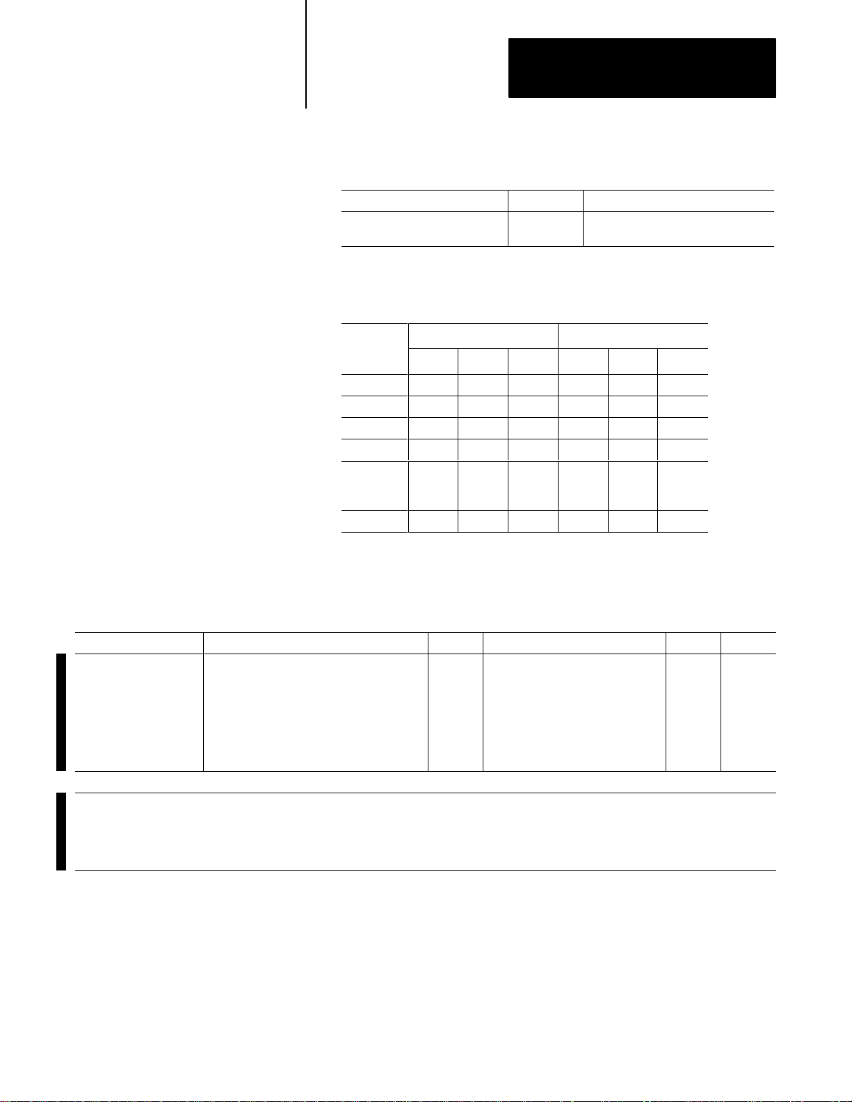
Summary of Changes
Summary of Changes
This release of the PLC-5/VME VMEbus Programmable Controllers User
Manual contains new and updated information on PLC-5/VMEt systems.
For infornmation about: See chapter/appendix:
CE compliance 2
making VME self-references in POST tests 2
improved .WRDY and .LOCK bit description 3
changes to the status file 4
setting the NOCV bit to 0 7
revised specifications C
additional troubleshooting tips D
To help you find new and updated information in this release of the
manual, we have included change bars as shown to the left of
this paragraph.
In addition to the new and updated information discussed above, we have
altered the way we reference software documentation in this manual.
Rather than show specific screens and key sequences which may vary
according to the software package you are using, we refer you instead to
the programming software documentation that accompanies your particular
software package. Of course, we still provide the basic background
information you need to accomplish your programming tasks, but if you
have specific questions, you should refer to your programming software
documentation set.
vii
Page 9

Using this Manual
Preface
Manual
Objectives
What this Manual Contains
The purpose of this manual is to familiarize you with the installation and
use of the PLC-5/VME programmable controllers. This manual focuses on
the specific VMEbus aspects of this processor. Typically, you use this
processor in a VMEbus system with one or more host CPU modules that
control(s) and communicate(s) with the processor. You need to develop
software driver programs to execute on the host CPU module(s) to
accomplish this. You must also write ladder programs for your processor
to monitor and control the I/O of your control system. This manual helps
you write the VMEbus-specific aspects of these programs.
Chapter/
Appendix
Title Contents
1 Overview Overview of the PLC-5/VME processors
2 Installation Configuration and installation procedures
3 VMEbus Interface Configuration registers and commands
4 Ladder-Program Interfaces How to interact with your VMEbus environment from
your ladder program
5 Commands Commands used to interface to the processor
6 PLC-5/VME Processor
Communications Commands
7 Performance and Operation Overview of the performance and operation of the
A Sample Applications How to write applications to interact with your
B Sample API Modules How to write API modules to interact with your
C Specifications PLC-5/VME processor specifications
D Troubleshooting Troubleshooting and error-code information
E Cable Connections Communication boards and cable connections for
The function of the extended PCCCs in the
PLC-5/VME processor
PLC-5/VME processor
PLC-5/VME processor
PLC-5/VME processor
family processors
PLC-5
Audience
This manual assumes that you have background in:
VMEbus concepts and basics
PLC-5 ladder logic
PLC-5/VME operation
C-language programming
iii
Page 10

Preface
Using this Manual
Terms and Conventions
We refer to the: As the:
Data Highway DH link
Data Highway Plus
Programmable Logic Controller processor
PLC-5 Processor
Programmable Controller
Communications Commands
Release on request ROR
Release when done RWD
Term Definition
Extended-local I/O I/O connected to a processor across a parallel link, thus limiting its
Extended-local I/O link a parallel link for carrying I/O data between a PLC-5/V40L
Remote I/O link a serial communication link between a PLC-5 processor port in
Remote I/O chassis the hardware enclosure that contains an adapter and I/O modules
Discrete-transfer data data (words) transferred to/from a discrete I/O module
Block-transfer data data transferred, in blocks of data up to 64 words, to/from a block-
distance from the processor
processor and extended-local I/O adapters
scanner mode and an adapter as well as I/O modules that are
located remotely from the PLC-5 processor
that are located remotely on a serial communication link to a
PLC-5 processor in scanner mode
transfer I/O module (for example, an analog module)
DH+ link
PLC-5/VME processor. Unless noted otherwise,
we use PLC-5/VME processor to denote all processors.
PCCC
iv
In addition, you may encounter words in different typefaces. We use these
conventions to help differentiate descriptive information from information
that you enter while programming your processor.
The Enter key looks like this (boldface and in brackets):
[Enter]
Words or commands that you enter appear in boldface. For example:
CTV # SVI
Variables that you enter appear in italics. For example:
vmeaddr width
“Type” means type in the information.
“Enter” means type in the information and then press the [Enter] key.
Page 11

Preface
Using this Manual
Related Publications
The 1785 PLC-5 programmable controller documentation is organized
into manuals according to the tasks that you perform. This organization
lets you find the information that you want without reading through
information that is not related to your current task.
Enhanced PLC-5
Processors System
System Overview
Overview of processor
specifications. selection,
and justification information
1785-2.36
Enhanced and Ethernet
PLC-5 Programmable
Controller User Manual
Explanation of processor
functionality, system
design, and programming
considerations
1785-6.5.12
1785 PLC-5
Programmable Controllers
Quick Reference
Quick access to switches,
status bits, indicators,
instructions, SW screens
1785-7.1
For more information on 1785 PLC-5 programmable controllers or the
above publications, contact your local Allen-Bradley sales office,
distributor, or system integrator.
We also suggest that you acquire the following publications for reference:
Data Highway / Data Highway Plus DH-485 Communication Protocol
and Command Set Reference, Allen-Bradley, publication 1770-6.5.16
The VMEbus Specification—Rev: C.1, Motorola, HB212
VMEbus User’s Handbook, Steve Heath, CRC Press, ISBN
0-8493-7130-9
v
Page 12

Overview
Chapter
1
Chapter
Features
Objectives
Read this chapter to understand the overall operation of the PLC-5/VME
processor, how you can use it in VME systems, and how its features and
functions relate to those of other Allen-Bradley processors.
PLC-5/VME processors are programmable controllers that bring the
technology of the 1785 PLC-5 processor to the VMEbus environment.
The PLC-5/VME processor is equivalent (in terms of I/O, ladder
programming, and instruction timing) to the standard PLC-5 processor,
except that the PLC-5/VME processor:
plugs into a VMEbus system
has a VMEbus communication interface designed for use with other
VMEbus CPU modules
can access VMEbus I/O modules
has no EEPROM memory module
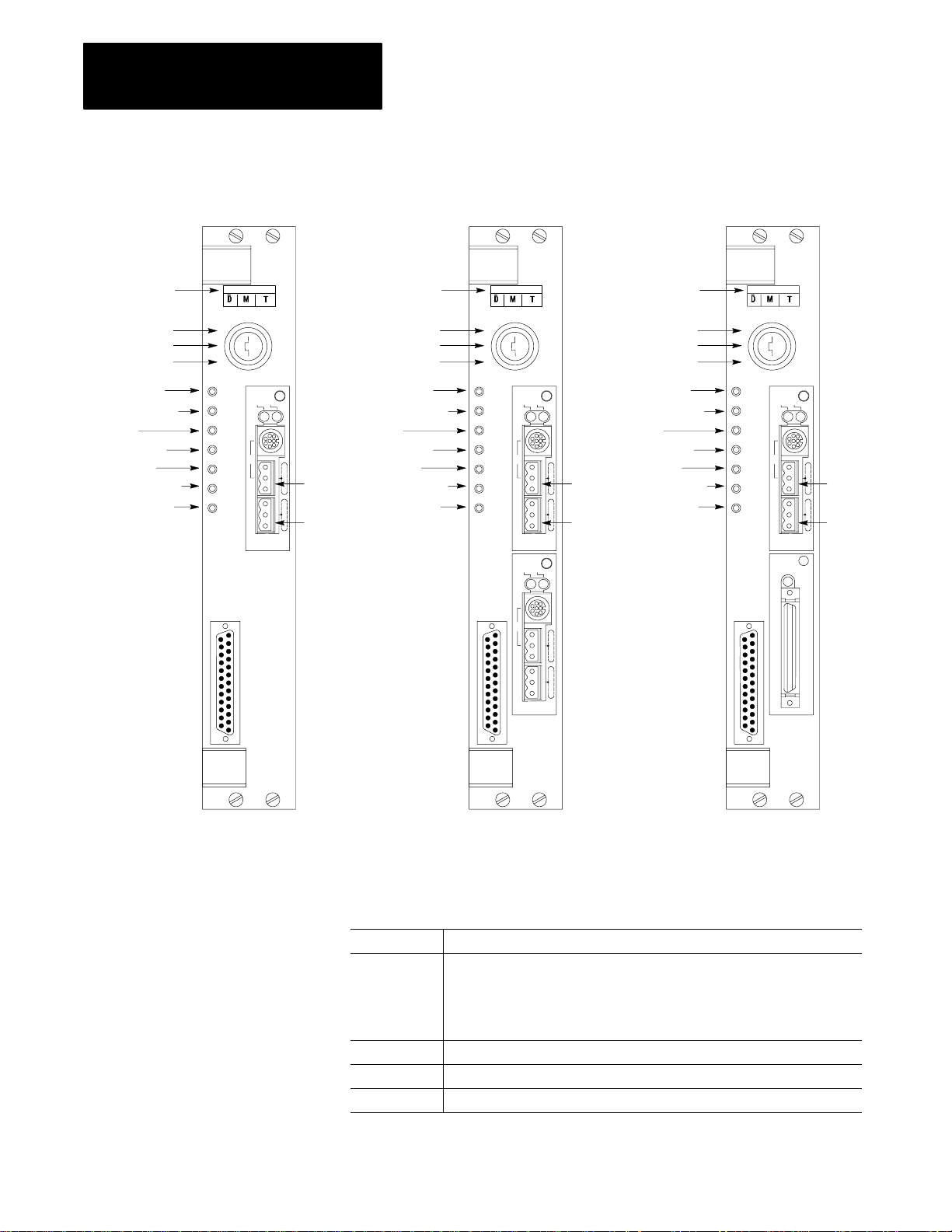
Figure 1.1 shows examples of the PLC-5/VME processors.
1-1
Page 13
Chapter 1
Overview
Figure 1.1
Examples
of PLC-5/VME Processors
Battery installed
Program
Remote
Run
Battery low
Proc run/Fault
Force
Ch 0 Status
SYSFAIL
Master Access
Slave Access
Chan 0
Chan 1
Battery installed
1A
1B
Program
Remote
Run
Battery low
Proc run/Fault
Force
Ch 0 Status
SYSFAIL
Master Access
Slave Access
Chan 0
Chan 1
Chan 2
Battery installed
Battery low
Proc run/Fault
Force
Ch 0 Status
SYSFAIL
1A
Master Access
Slave Access
1B
Program
Remote
Run
Chan 1
1A
1B
Chan 0
Chan 2
1-2
PLC-5/V30B processor
PLC-5/V40B or -5/V80B processor PLC-5/V40L processor
19499
All PLC-5/VME processors have at least one configurable I/O channel and
one serial port (channel 0).
Channel: Is configured for:
0 supporting RS-232C
The PLC-5/VME processor channel 0 protocol defaults to the system mode of
operation (DF1 point-to-point), which allows programming from a PC terminal.
The default communication rate is 2400.
1A DH+ mode (by default)
1B scanner mode (by default)
2 (if applicable) DH+ and remote I/O (RIO) communication or extended-local I/O
Page 14

Chapter 1
Overview
In the PLC-5/V40B, both channels (1 and 2) are identical although they are
independently configurable. In the PLC-5/V40L, channel 2 is a local I/O
(LIO) interface.
The PLC-5/VME processor has the same instruction set as the standard
PLC-5 processor. It supports:
complex expressions in compare and compute instructions
statistical instructions
floating-point calculations in PID instructions
ASCII string-handling instructions
main control programs (MCPs)
Use the keyswitch to change the mode in which a processor is operating.
If you want to: Turn the keyswitch to:
•
Run your program, force I/O, and save your programs to a
disk drive. Outputs are enabled. (Equipment being
controlled by the I/O addressed in the ladder program begins
operation.)
•
Enable outputs.
Note:
You cannot create or delete a program file, create or
delete data files, or change the modes of operation
through the programming software while in
run mode.
•
Disable outputs
•
Create, modify, and delete ladder files or data files;
download to an EEPROM module; and save/restore
programs.
Notes:
•
The processor does not scan the program.
•
You cannot change the mode of operation through
the programming software while in program mode.
RUN
PROG
R
E
M
RUN
PROG (program)
PROG
R
E
M
RUN
Change between remote program, remote test, and remote run
REM (remote)
modes through the programming software.
Remote run
•
Enable outputs.
•
You can save/restore files and edit online.
Remote program
PROG
RUN
See the program-mode description above.
Remote test
•
Execute ladder programs with outputs disabled.
•
You cannot create or delete ladder programs or data files.
R
E
M
1-3
Page 15
Chapter 1
Overview
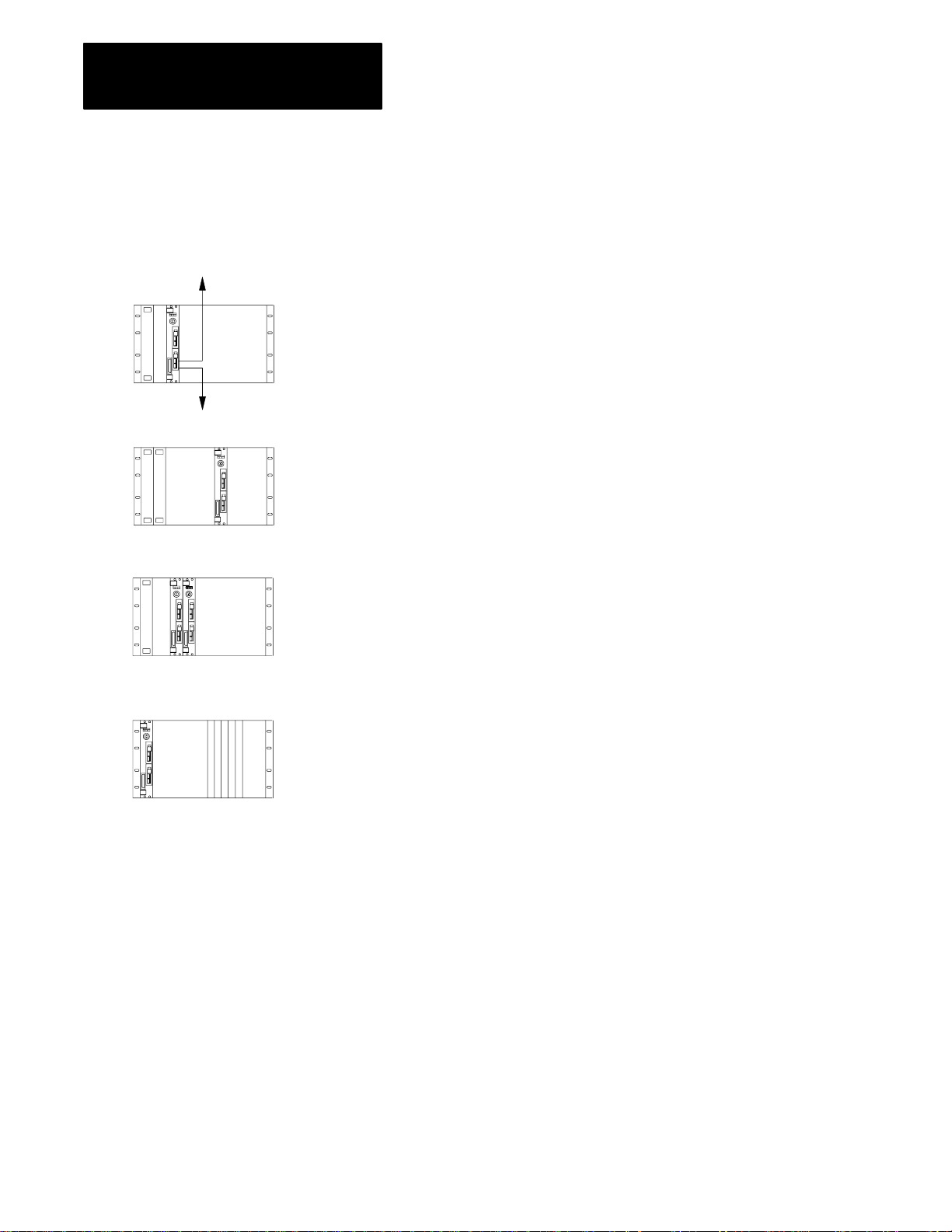
System Description
CPU
PLC-5/VME
processor
CPUs
PLC-5/VME processor
CPU
DH+ link
Remote I/O
or ExtendedLocal I/O
19500
Use the PLC-5/VME processor in a 6U (full-height) VMEbus chassis. You
can use the PLC-5/VME processor by itself (i.e., with no other VME
modules), but typically the PLC-5/VME processor is used in conjunction
with other VMEbus computers (CPUs) and I/O modules. The examples
below illustrate possible configurations.
The
PLC-5/VME processor is used in conjunction with a VMEbus CPU module. The
processor serves as a real-time I/O processor under the direction of the CPU. The
processor is a slave of the CPU, where, in addition to its normal ladder logic and I/O
processing in each scan loop, the processor responds to directions from the CPU and
passes data back to the CPU.
There is no fixed relationship between processor and CPU, so multiple CPUs can
communicate with one processor. Multiple CPUs run multiple tasks, all sending and
receiving data from the processor at the same time.
One CPU can control multiple PLC-5/VME processors. Each processor maps into the
VMEbus address space; so you map each processor to a different address space.
PLC-5/VME processors
PLC-5/VME processor
19500
No CPU interacts with the processor
or more remote I/O racks and has the capability
. The processor interacts with I/O modules in one
, from its ladder program, of generating
VMEbus accesses. This means that the processor can access VMEbus I/O modules
as well.
1-4
Page 16
Chapter 1
Overview
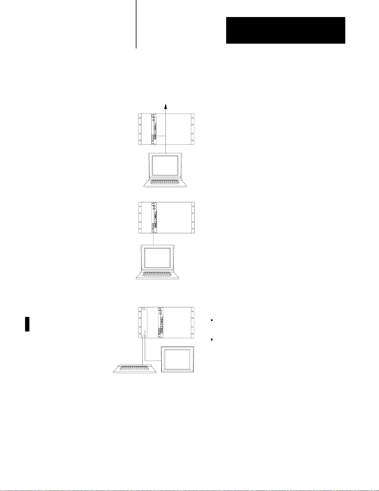
The following diagrams show three basic configurations for programming
and debugging your ladder-logic programs.
PLC-5/VME
processor
DH+ link
Connect
1784-KT communication device in your IBM A
a computer via the DH+ link, typically using a
T computer
and a 1784-CP6 cable.
PLC-5/VME processor
RS-232
PLC-5/VME processorPC/CPU
19501
Connect a computer using the RS-232C on-board serial
port of the PLC-5/VME processor
RS-232C cable connects one of the computer
to the channel 0 (serial) port of the processor
ou can program as well as download files directly over the
Y
. In this configuration, the
’
s COM ports
.
VMEbus backplane to your PLC-5/VME processor if you:
run 6200 Series PLC-5 Programming Software release
4.4 or later
use an 8086-based CPU from RadiSys—i.e., a EPC-1,
EPC-4, or EPC-5 VME PC-compatible computer
Important:
In order to use the
save
feature of the 6200
.
Series PLC-5 Programming Software when you
communicate with the processor in this way
release 4.5 or later
.
, you must run
1-5
Page 17
Chapter 1
Overview
VMEbus Interface
Configuration/control/
status/message
registers in A16 space
Optional general-purpose
memory in A24 space
VMEbus
The PLC-5/VME is fully compliant with the C.1 VMEbus specification.
The PLC-5/VME processor occupies two 6U VMEbus slots. It can reside
in any adjacent pair of slots, including slot 1, the system-controller slot.
The PLC-5/VME processor has a single VMEbus P1 connector, allowing it
to be used in VMEbus systems that have either the full J1 and J2
backplanes or only the J1 backplane.
The PLC-5/VME processor occupies 64 bytes in the VME A16 (or
“short”) address space, and you can configure an additional 64 Kbytes of
the A24 (or “standard”) address space.
The
PLC-5/VME processor has 8 16-bit registers accessible in the VMEbus A16 address
space. A set of switches establishes the base address of these registers. These
registers can be used by a VMEbus CPU to establish certain programmable configuration
options of the processor, control and monitor certain low-level conditions, and send
commands to the processor
The PLC-5/VME processor also has 64 KB of memory that can be enabled and mapped
in the VME A24 address space. This memory is a general-purpose memory that you can
use for any purpose (or not at all). If you enable it and tell the processor to do something
to a VME address that happens to fall into this 64KB memory, the processor can access it
without actually using VMEbus cycles. If you need some global VMEbus memory that
can be accessed by the processor and another CPU, there may be performance benefits
to using this 64KB of memory
.
.
Processor
1-6
Page 18

Ladder
programs
Processor
data
Files
Chapter 1
Overview
Figure 1.2 illustrates the basic forms of communications. Table 1.A
summarizes these communication forms.
Figure 1.2
Basic
Forms of Communications
1
Commands sent to the processor
2
3
4
5
6
7
8
9
10
11
Read/write accesses to the processor’s A16 registers and/or
the A24 memory block
Interrupt to a ladder program
Interrupt signalled by a ladder program
One-shot block copy into or out of processor data files
Continuous block copies into or out of processor data files
Interrupt signalling command completion
Interrupt signalling completion of one block copy
One-shot block copy into or out of processor data files as a
result of some commands sent to the processor
VMEbus SYSRESET
VMEbus SYSFAIL
VME status file
12
13
1
Required
VMEbus ACFAIL
1
Optional VMEbus system controller functions
by the PLC-5/VME processor
. Asserted by VME power supply
.
1-7
Page 19

Chapter 1
Overview
T
able 1.A
Summary
of Figure 1.2
In Figure 1.2,
It means that:
when you see :
Commands are high-level directives sent to the processor from another VMEbus master, typically a
controlling CPU. Commands specific to the VME processor can establish a continuous block copy to/from
1
the processor and tell the processor to which VMEbus interrupts it should respond. You can also send any
PCCC via this mechanism. PCCCs are commands supported in all 1785 PLC-5 processors. You can use
them to change and modify processor state, for example, or to upload and download memory files.
2
The PLC-5/VME processor responds as a VMEbus slave to certain A16 accesses (to its configuration
registers) and to certain A24 accesses (to its general-purpose memory, if enabled).
You can configure the PLC-5/VME processor to respond as an interrupt handler to specified VMEbus
3
interrupt lines. When one of these interrupts occurs, the processor performs an 8-bit interrupt acknowledge
cycle on the VMEbus to read an 8-bit status/ID from the interrupter. The interrupt and the status/ID value
are then posted for accessibility by the ladder program.
The PLC-5/VME processor can perform as a VMEbus interrupter (sender of interrupts) in three
different ways:
4
•
•
•
Another function available via the MSG instruction is VMEbus reads and writes. Rather than just individual
5
8- or 16-bit accesses, the function allows a block read or write to be done (i.e., of an arbitrary number of
bytes). This is done between a data file in the processor and an arbitrary address range on the VMEbus.
The ladder program can specify the VMEbus address space and data widths to be used.
One of the main interfaces of the 6008-LTV processor, and one preserved in the PLC-5/VME processor, is
6
the ability to predefine two block-copy operations, one into the processor data files and one out of the
processor data files, to be executed automatically every scan loop. These operations are predefined to the
processor via initialization commands from the CPU or from your programming software.
7
The processor can be a VMEbus interrupter signalling completion of a command. This is an option on all
commands and can serve as a way to synchronize the CPU and the processor.
The processor can be a VMEbus interrupter signalling completion of each block copy operation for the
8
continuous copy operations. This is another option that allows the CPU to synchronize with the scan loop
of the processor.
9
Certain standard PCCC commands cause data to be moved into and out of the processor; thus these
commands represent another type of VMEbus interface between the processor and a controlling CPU.
The PLC-5/VME processor can be reset with the VME SYSRESET
10
also asserts SYSRESET
responding to VMEbus accesses.
The PLC-5/VME processor asserts the VME SYSFAIL
11
completes successfully. The PLC-5/VME processor makes the state of the VME SYSFAIL
available to the ladder program.
Assertion of VME ACFAIL
12
maintained in the battery-backed memory such that the processor can be restarted upon power up. Your
power supply must assert ACFAIL
The PLC-5/VME processor can serve as a VMEbus slot-1 system controller. This enables the PLC-5/VME
13
processor as a single-level arbiter, a bus timeout timer, and the driver of the VMEbus 16 MHz
SYSCLK signal.
1
indicates a low true signal.
from a ladder program; the ladder MSG instruction has been extended in the PLC-5/VME processor to
allow a ladder program to generate a VMEbus interrupt.
signalling completion of a command (see 7).
signalling a completion of each block copy operation for the continuous copy operations (see 8).
1
1
during power-up initialization until its VMEbus interface hardware is capable of
1
signal after a reset until the firmware’s self-test
1
causes the processor to halt, with integrity of the ladder program and data files
1
at least 9ms in advance of the +5VDC supply dropping beneath 4.75V.
signal. The PLC-5/VME processor
1
signal
1-8
Page 20

Chapter 1
Overview
Compatibility with the Standard PLC-5 Processor
Ladder programs from a standard PLC-5 processor run in the PLC-5/VME
processor. The PLC-5/VME processor has the same program scan time as
the PLC-5 processor. The PLC-5/VME processor has the same extended
instruction set as the PLC-5 processor.
Features of the PLC-5 processor not present in the PLC-5/VME
processor are:
PIIs
EEPROM memory module
logical rack 0 (128 less I/O points)
Features of the PLC-5/VME processor not present in the PLC-5
processor are:
The PLC-5/VME processor defines a special data file called the “VME
status file.” This file gives ladder programs the ability to control and
monitor certain VMEbus state information.
The ladder MSG instruction is extended to allow ladder programs to
perform VMEbus data transfers and generate VMEbus interrupts.
Finally, features present in both but implemented or represented
differently are:
Compatibility with the
6008-L
TV Processor
The serial port (channel 0) on the PLC-5/VME processor is RS-232C
only (not configurable for RS-422 and RS-423).
Different batteries are used (cat. no. 1770-XYV).
The PLC-5/VME processor has a memory-protect switch. In the PLC-5
processor, the equivalent switch is on the 1771 I/O rack.
The PLC-5/VME processor retains a significant amount of compatibility
with the 6008-LTV processor. This eases the task of converting 6008-LTV
ladder programs and CPU driver programs to use with the PLC-5/VME
processor.
6008-LTV ladder programs may need editing because the VME status file
in the PLC-5/VME processor is different in several ways from 6008-LTV
status file. The 6008-LTV ladder programs that access the VME status file
will need to be changed.
1-9
Page 21

Chapter 1
Overview
T
able 1.B
Comparison
Attributes 6008-LTV PLC-5/VME Comments
VME slots 3 2
Bus arbitration No Yes or No (user configurable) Single level arbiter
VME master Yes Yes
VME Slave Yes Yes
Global memory (bytes)
Programming and downloading
over backplane
Saving over backplane No Yes With 6200 series software
PLC data table to global memory transfer method
Asserts VME SYSFAIL Yes Yes
PLC resets upon VME SYSRESET Yes Yes
Bus request line 0, 1, 2, 3 1, 3
Bus release ROR, RWD, ROC ROR, RWD, ROC
Continuous-copy command file size 500 words 1000 words
Ladder MSG file size N/A 1000 words
RS-232 port No Yes
Remote I/O baud rate 57.6k baud fixed 57.6k, 115.2k, 230.4k baud configurable
Remote I/O fractional rack addressing No Yes
1
All
of the 6008-L
VME short memory
1
TV’
s global memory could be configured to be totally within short memory
, it can only be selected with a standard memory address. This may be a consideration when replacing a 6008-LTV with a PLC-5/VME processor
1K short, 4K short or standard 64K standard Global memory is selectable
No Yes With 6200 series software
Continuous-copy command Continuous-copy and/or ladder
of 6008-LTV and PLC-5/VME Processor Attributes
release 4.4 and later
release 4.5 and later
MSG commands
. Because the PLC-5/VME processor
’s global memory would totally fill all of
.
1-10
There are some areas of potential incompatibility to consider:
The configuration/control/status/message registers are slightly different,
requiring changes to the host driver program.
The LTV VME global memory can be selected to be in short or standard
memory space. The PLC-5/VME processor’s global memory can only
be selected to be in standard memory. Because of this, the 6008-LTV
will accept address modifiers 2D, 3D 29 and 39. The PLC-5/VME
processor will only respond to address modifiers 3D.
The 6008-LTV supports logical rack address 0; the PLC-5/VME
processor does not.
The 6008-LTV has a status/configuration bit to enable or ignore ROC
(release on clear). The PLC-5/VME processor will always respond
to ROC.
Page 22

Chapter 1
Overview
The PLV-5/VME processor status files in the processor status area are
different in several ways.
When floating point values are converted to integer, they are rounded
differently. 6008-LTV rounds 0.5 to the next highest integer, the
PLC-5/VME processor rounds to the nearest even integer.
CPU driver programs are affected in these ways:
The low-level protocol for how commands are given to the processor
and how command-sending errors are reported is significantly different.
However, the higher-level interfaces (e.g., the commands themselves)
are compatible.
The manner in which the VME setup interface parameters are
configured is significantly different:
In the: The information is in the:
PLC-5/VME processor configuration registers in the A16 space.
6008-LTV processor “Slave 0” global memory in the A16 space.
See chapter 3 for more information.
1-11
Page 23

Installation
Chapter
2
Chapter
Objectives
Compliance to
European Union Directives
Read this chapter to learn how to set the switches in your PLC-5/VME
processor and install it into a VMEbus chassis.
See the Classic 1785 PLC-5 Programmable Controller Hardware
Installation Manual, publication 1785-6.6.1 for more information about
installing PLC-5 family processors.
If this product has the CE mark it is approved for installation within the
European Union and EEA regions. It has been designed and tested to meet
the following directives.
EMC Directive
This product is tested to meet Council Directive 89/336/EEC
Electromagnetic Compatibility (EMC) and the following standards, in
whole or in part, documented in a technical construction file:
• EN 50081-2EMC – Generic Emission Standard, Part 2 – Industrial
Environment
• EN 50082-2EMC – Generic Immunity Standard, Part 2 – Industrial
Environment
This product is intended for use in an industrial environment.
Low Voltage Directive
This product is tested to meet Council Directive 73/23/EEC Low Voltage,
by applying the safety requirements of EN 61131–2 Programmable
Controllers, Part 2 – Equipment Requirements and Tests.
For specific information required by EN 61131-2, see the appropriate
sections in this publication, as well as the following Allen-Bradley
publications:
• Industrial Automation Wiring and Grounding Guidelines For Noise
Immunity, publication 1770-4.1
• Enhanced and Ethernet PLC-5 Programmable Controller User
Manual, publication 1785-6.5.12
• Guidelines for Handling Lithium Batteries, publication AG-5.4
• Automation Systems Catalog, publication B111
2-1
Page 24
Chapter 2
Installation
Handling the Processor
Wrist strap
19897
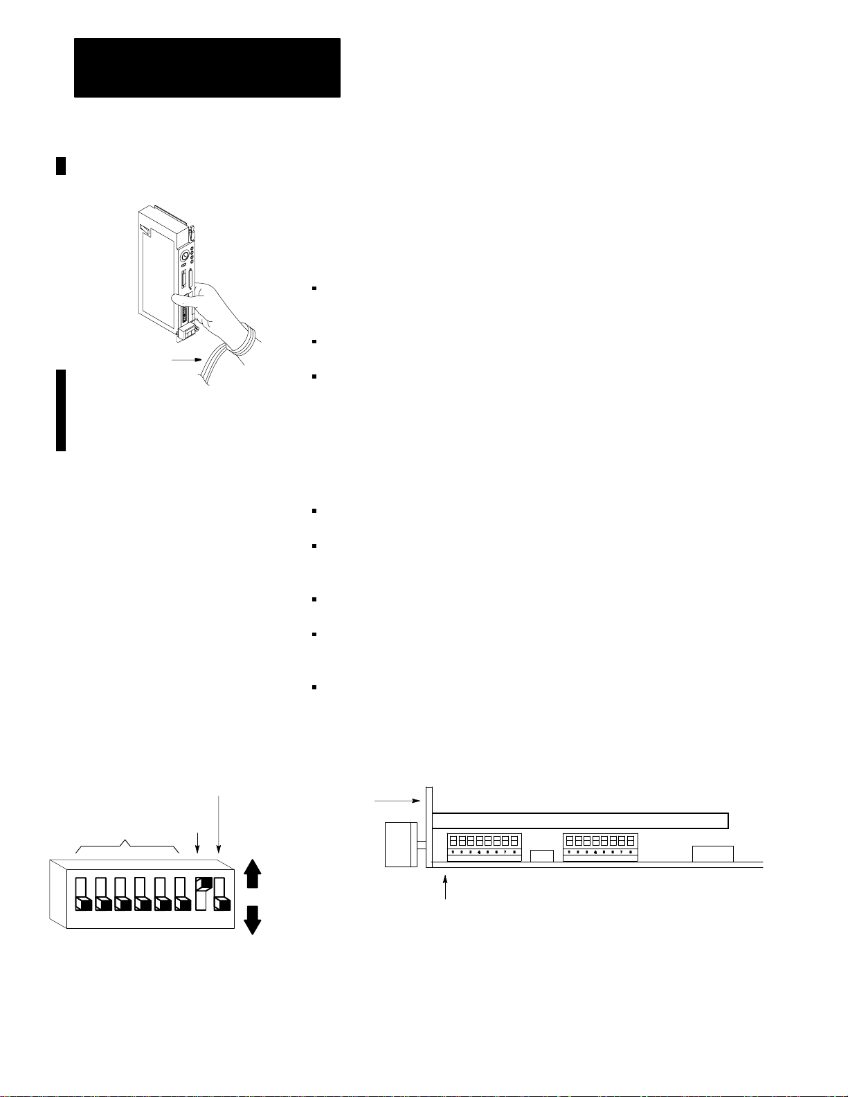
Setting the Switches
The processor is shipped in a static-shielded container to guard against
electrostatic damage. Electrostatic discharge can damage integrated
circuits or semiconductors in the processor module if you touch backplane
connector pins. It can also damage the module when you set configuration
plugs or switches inside the module. Avoid electrostatic damage by
observing the following precautions.
Remain in contact with an approved ground point while handling the
module (by wearing a properly grounded wrist strap).
Do not touch the backplane connector or connector pins.
When not in use, keep the module in its static-shielded container.
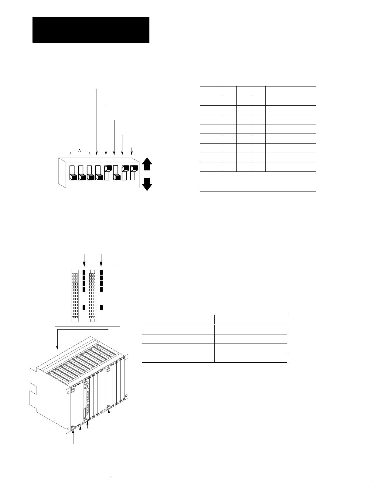
Before installing the PLC-5/VME processor, you need to make some
decisions about its configuration and operation and set the switches on the
circuit board accordingly. You need to know:
DH+ station (node) number
Memory protection—whether you want the processor’s program
RAM protected
Memory
protect
DH+ station
number
12345678
SW1 set of switches
Powerup Test
Up
(off)
Down
(on)
Location of configuration registers in VMEbus A16 address space
System controller—whether you want the processor to serve as the
VMEbus slot-1 system controller
VMEbus request level—whether you want the processor to request
access to the VMEbus at level 3 or level 1
Figure 2.1
Switch
Location
Front plate
SW1
Bottom
SW2
Table 2.A and Table 2.B describe the switch settings for SW1.
19502
2-2
Page 25
Chapter 2
Installation
T
able 2.A
SW1
Set of Switches
Switches 1-6 Switch 7 Switch 8
DH+ station number for channels
1A and 0 (see Table 2.B)
T
able 2.B
Station
Numbers SW1 (Switches 1-6)
Station
Number
(Octal)
1
2 3 4 5 6
0 on on on on on on
1 off on on on on on
2 on off on on on on
3 off off on on on on
.
.
.
.
.
.
.
.
.
77 off off off off off off
Unused (off) Memory protect.
If on, RAM memory protect is enabled.
LSD MSD
.
.
.
.
.
.
.
.
.
.
.
.
Table 2.C and Table 2.D describe the switch settings for SW2.
T
able 2.C
SW2
Set of Switches
Switches 1-3 Switch 4 Switch 5 Switch 6 Switch 7 Switch 8
A16 address range of the
configuration registers.
See Table 2.D.
Important: Switch 6 is meaningful only if switch 4 is off.
1
SW2,
position 7,
now
self-references as it did before series C, revision K. If you set SW2, position 7 to ON (down position), then the POST test will skip all VME self-references, causing the following ef
– The PLC-5 processor cannot test its bus-master hardware.
– The PLC-5 processor cannot determine its own unique logical address and assumes its ULA is F0H regardless of how you set SW2, positions 1–3.
– The VME status file ULA field (word 1, bits 3-15) will always contain 000, regardless of how you set SW2, positions 1–3.
If on, the processor functions as the VMEbus
system controller, and no other VME cards
should attempt to be the system controller.
Important: The PLC-5/VME processor must
be in the left-most slot of the VME chassis.
See page 3-1 for a description of the
system controller.
controls whether the PLC-5 processor makes a VME self-reference in its POST test. If you set SW2, position 7 to OFF (up position), then the VME will make
Unused
(off)
VMEbus request level.
If switch 4 is OFF, switch 6 on defines
Unused
(off)
the bus request level as 3. If switch 6
is OFF, the bus request level is 1.
If switch 4 is ON, the bus request
level is 3 independent of the setting
of switch 6.
Unused
1
(off)
fects:
2-3
Page 26
Chapter 2
Installation
System
controller
Unused
(off)
Request
level
Unused
A16
address
range
12345678
SW2 set of switches
(off)
Unused
(off)
Up
(off)
Down
(on)
T
able 2.D
Address
Range SW2 (Switches 1-3)
1
ULA
1 2 3 A16 Address Range
0 on on on FC00-FC3F (hex)
1 off on on FC40-FC7F
2 on off on FC80-FCBF
3 off off on FCC0-FCFF
4 on on off FD00-FD3F
5 off on off FD40-FD7F
6 on off off FD80-FDBF
7 off off off FDC0-FDFF
1
Unique
Logical Address is used by the 6200 series
programming
the
software to determine the A16 base address
PLC-5/VME processor’s registers..
of
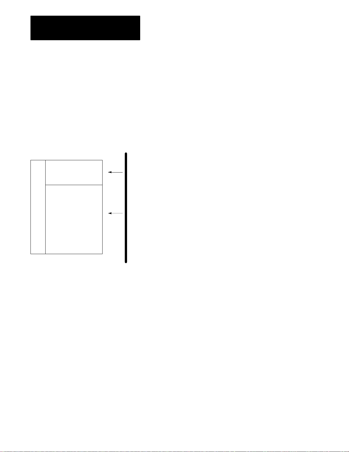
Configuring
the VME
Backplane Jumpers
Five backplane jumpers
Left
connector
Backplane
Right
connector
The VMEbus contains several daisy-chained control signals. Almost all
VMEbus backplanes contain jumpers for these control signals to allow
systems to operate with empty slots. Failing to install these jumpers
properly is a common source of problems in configuring a new
VMEbus system.
There are five jumpers per VME slot, one for each of the four bus-grant
arbitration levels and one for the interrupt-acknowledge daisy chain.
Depending on the backplane manufacturer, the jumpers can be on the
rear pins of the J1 connector or alongside it on the front of the backplane.
The PLC-5/VME processor uses two slots. Based on what is in the VME
slot, install or remove the backplane jumpers as follows:
VME Slot Content Five Backplane Jumpers
PLC-5/VME processor’s left slot Remove
PLC-5/VME processor’s right slot Install
Empty slot Install
Other VME module Consult manufacturer’s literature
Note: Consult
manufacturer’s
literature.
2-4
Other VME module
PLC-5/VME processor
Empty
CPU
Page 27
Chapter 2
Installation
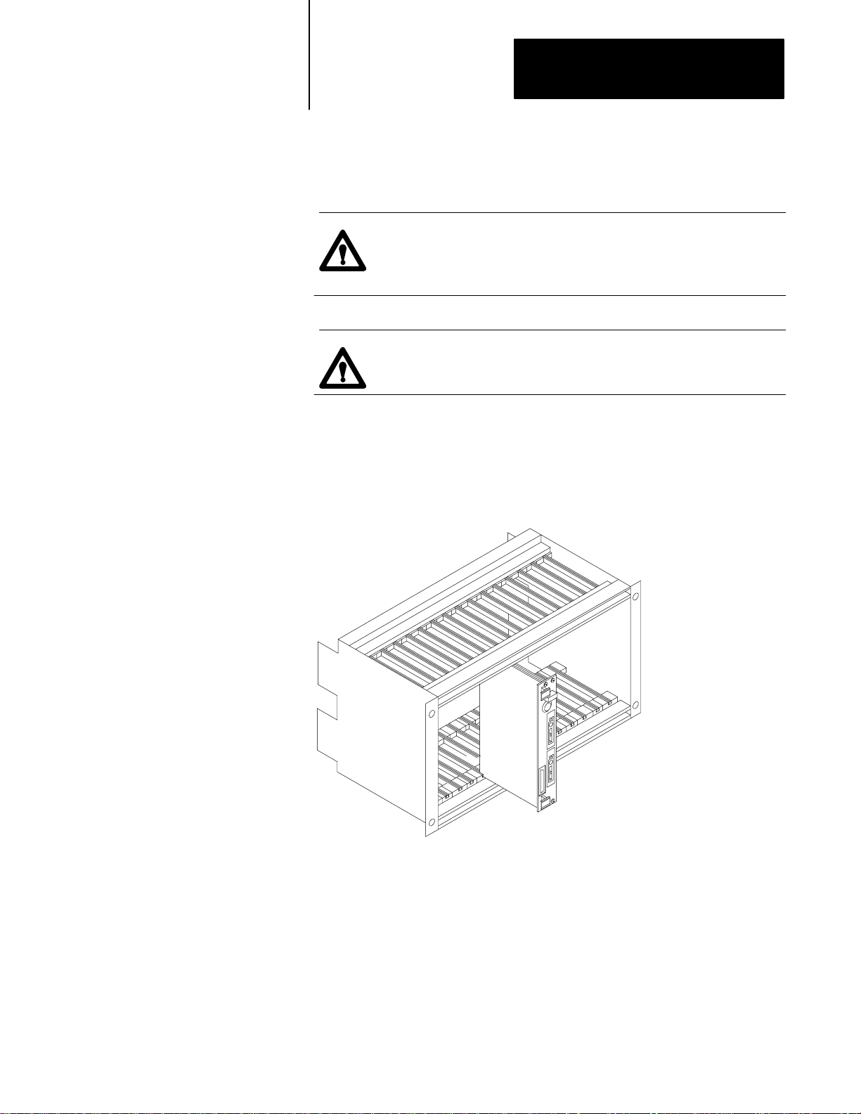
Inserting
the Processor
into a Chassis
You insert the PLC-5/VME processor in two adjacent slots in a 6U
(full-height) VMEbus chassis.
ATTENTION: Make sure that your VME system is powered
off. The PLC-5/VME processor is not designed to be inserted
or removed from a live system.
ATTENTION: Avoid touching the circuit board
and connectors.
After sliding the processor into the VME chassis using its cardguides, use
firm pressure on the top and bottom handles of the processor to make its
P1 connector fit firmly into the connector on the backplane. Tighten the
screws in the top and bottom of the front panel to prevent your
PLC-5/VME processor from loosening.
Grounding
19556
Allen-Bradley makes specific recommendations for properly grounding its
racks so that their operation is as safe and error-free as possible. VME
systems, on the other hand, may have no formal specifications for
grounding the VME chassis frame. Allen-Bradley recommends that you
ground the VME chassis frame and that you connect the logic ground
(common) of the VME power supply to the chassis frame’s earth ground.
2-5
Page 28
Chapter 2
Installation
The specific procedure for grounding a VME chassis varies depending on
the style of the chassis. Read the instructions found in the Classic PLC-5
Family Programmable Controllers Installation Manual, publication
1785-6.6.1 for information on how Allen-Bradley racks are grounded, and
try to ground your VME chassis frame in a similar way.
ATTENTION: If you are using a PLC-5/V40L processor,
your VME power supply should not float with respect to earth
ground. Connect the power supply’s logic ground (common)
for the 5V supply before connecting the PLC-5/40L processor
to a 1771-ALX adapter. Also, use a single point of ground
between the VME chassis and the extended-local I/O system to
ensure proper performance.
Determining Power-Supply Requirements
Connecting to Remote I/O
The PLC-5/VME processor draws 4 A (maximum)—3.2 A (typical)—from
the VME power supply. The processor also monitors the ACFAIL signal
on the backplane to determine when the +5 VDC supply is within
tolerances. The VME power supply must assert ACFAIL at least 9 ms in
advance of the +5 VDC supply dropping beneath 4.75V or memory
corruption and processor fault occurs. Therefore, make sure that your
power supply has ACFAIL capability.
You must use a Safety Extra Low Voltage (SELV)- or Protected Extra Low
Voltage (PELV)-certified power supply with the VME processor to comply
with Low Voltage directive requirements.
Use Belden 9463 twin-axial cable (cat. no.1770-CD) to connect devices to
a remote I/O link. To connect a remote I/O link, do the following:
To connect a remote I/O link, you must: See page:
Make sure the cables are the correct length 2-6
Prepare the cable 2-7
Make the remote I/O connections 2-7
Terminate the link 2-8
2-6
Make Sure that You Have Correct Cable Lengths
Verify that your system’s design plans specify remote I/O cable lengths
within allowable measurements.
Page 29

Chapter 2
Installation
A remote I/O link using this communication rate: Cannot exceed this cable length:
57.6 kbps 3,048 m (10,000 ft)
115.2 kbps 1,524 m (5,000 ft)
230.4 kbps 762 m (2,500 ft)
Prepare the Cable
Cut the cable according to the lengths you need. Route the cable to
the devices.
Make Remote I/O Connections
Use Figure 2.2 when connecting the remote I/O cable to PLC-5 processors
and remote I/O adapter modules.
2-7
Page 30
Chapter 2
Installation
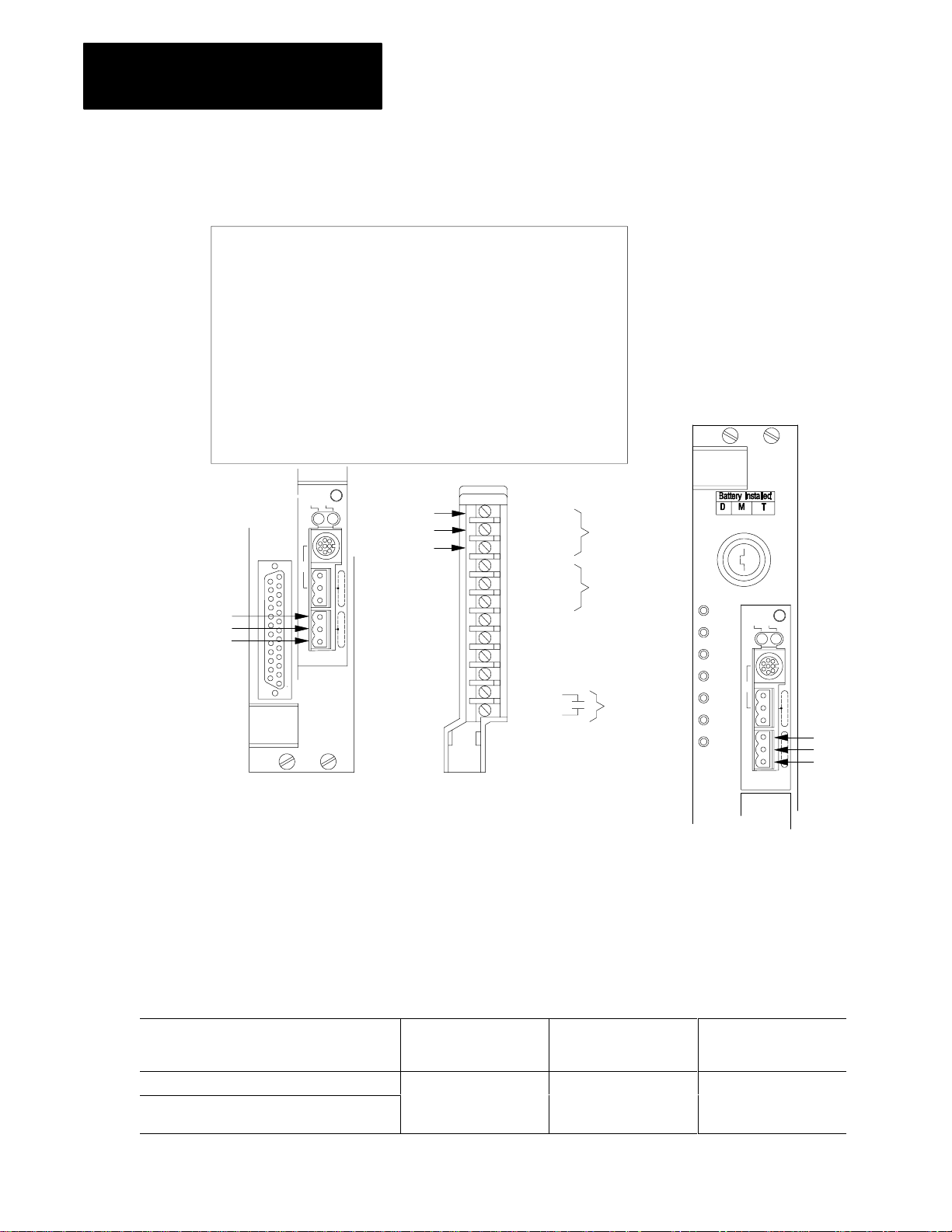
Figure 2.2
Remote
I/O Terminal Connectors
To connect remote I/O cable, do the following:
1. Run the cable (1770-CD) from the processor to each remote I/O
adapter module or processor in the remote I/O system.
2. Connect the signal conductor with blue insulation to the 3-pin
connector terminal labeled 1 on the processor and to each remote
I/O adapter module (or PLC-5 adapter) in the remote I/O system.
3. Connect the signal conductor with clear insulation to the 3-pin
connector terminal labeled 2.
4. Connect the shield drain wire to the 3-pin terminal labeled SH.
5. Tie wrap the remote I/O network cable to the chassis to relieve strain
on the cable.
Blue
Shield
Chan 0
Blue
Shield
Clear
Chan 2
PLC-5/V40B
Processor channel must be configured for remote I/O communication.
Clear
Remote I/O
Terminal
Connectors
1771-ASB Remote
I/O Adapter Module
1 Line 1
2 Shield
3 Line 2
4 Line 1
5 Shield
6 Line 2
7 No Connection
8 No Connection
9 No Connection
10 No Connection
11 In
12 Ret
Cable
Cable for
daisy-chain
configuration
Reset
Terminate the Link
For proper operation, terminate both ends of a remote I/O link by using the
external resistors shipped with the programmable controller. Use either a
150W or 82W terminator.
Remote I/O
Terminal
Connectors
Chan 1
PLC-5/V40L
Blue
Shield
Clear
19539
2-8
If your remote I/O link: Use this resistor rating: The maximum number of
operates at 230.4 kbps
operates at 57.6 kbps or 115.2 kbps and no
devices listed in Table 2.A are on the link
82
W
physical
devices you
can connect on the link
32 16
The maximum number of
racks you can scan on
the link
Page 31

Chapter 2
1775 S4A, S4B
Installation
If your remote I/O link: The maximum number of
contains any device listed in Table 2.A
Use this resistor rating:
150
W
The maximum number of
physical
devices you
can connect on the link
racks you can scan on
the link
16 16
operates at 57.6 kbps or 115.2 kbps, and you do
not require the link to support more than 16
physical devices.
As shown in the table above, the terminators you use determine how many
devices you can connect on a single remote I/O link.
T
able 2.A
I/O
Link Devices that Require 150-
Device Type Catalog Number Series
Scanners 1771-SN
1772-SD, -SD2
-
1775-SR
1775-S4A, -S4B
6008-SQH1, -SQH2
Adapters
Miscellaneous 1771-AF All
1771-AS
1771-ASB A
1771-DCM
W
T
ermination Resistors
All
To
Another I/O link device
Figure 2.3
Terminating
Blue
Shield
Clear
a Remote I/O Link Using a Resistor
I/O adapter
Blue
Sh ie ld
Clear
PLC-5/VME processor or remote I/O adapter module
as the last device on an remote I/O link.
Blue
Sh ie ld
Clear
1
2
150
or
82
Ω
Ω
19334
2-9
Page 32

Chapter 2
Installation
Connecting an ExtendedLocal I/O Link
Use the extended-local I/O cables. These cables have a single-end
connector on one end and a dual-end connector on the other. The
maximum cable length for an extended-local I/O system is 30.5 cable-m
(100 cable-ft). Connect extended-local I/O adapters by using any of these
cables (Table 2.B):
T
able 2.B
Standard
Cable Length: Catalog Number:
1 m (3.3 ft) 1771-CX1
2 m (6.6 ft) 1771-CX2
5 m (16.5 ft) 1771-CX5
Extended-Local I/O Cables
Important: You cannot connect or splice extended-local I/O cables to
form a custom cable length. For example, if you have a distance of four
meters between two extended-local I/O adapters or between a processor
and an extended-local I/O adapter, you cannot connect two 2-m cables
together. You would have to use the 5-m cable and have the extra meter
as slack.
You must set switches on the extended-local I/O adapter module. For
information, see its installation data, publication 1771-2.200.
2-10
Page 33

Chapter 2
Installation
To make extended-local I/O connections, do the following:
ATTENTION: Turn off power to the extended-local
I/O adapter module before connecting or
!
disconnecting extended-local I/O cables.
Do not apply power to an I/O rack containing
an extended-local I/O adapter module until
all extended-local I/O cables are installed
and connected.
1. Connect the single-end connector to channel 2 of the processor.
2. Route the cable to the first extended-local I/O adapter.
3. Connect the dual-end connector to the extended-local I/O
adapter module. Be sure to screw in the retaining screws tightly.
PLC-5/V40L processor
4.
If the adapter: Then:
is not the last one
on the link
is the last one
on the link
1. Connect the single-end of a
local I/O network cable to the
exposed end connector on the
adapter module. Press and
hold the clips and snap to the
mating connector.
2. Route the cable to the next
adapter and connect the
dual-end connector to it.
Terminate the link by installing the
local I/O terminator (1771-CXT) to
the exposed end of the dual-end
connector on the last adapter
module. The system will not run
without it. The terminator is included
with the processor.
ATTENTION: If you are not using any extended-local I/O
!
adapter modules, connect the extended-local I/O terminator,
1771-CXT, to channel 2 of the PLC-5/V40L processor to
ensure proper performance of the processor. This terminator is
included with your processor.
2-11
Page 34

Chapter 2
Installation
Connecting a DH+ Link
Chan
Chan 1
1A
1B
0
Chan 2
Chan 1
1A
1B
Chan 0
Chan 2
Once you connect the programming device through a local DH+ link to
one processor, the device can communicate with any PLC-5/VME
processor on the link. You can also communicate with PLC-2, PLC-3, and
PLC-5/250 processors connected to the link provided you have the
appropriate programming software installed.
The processor has electrically parallel DH+ connectors.
This processor: Has these electrically parallel DH+ connectors:
PLC-5/V40B
PLC-5/V80B
PLC-5/V40L
•
8-pin connector for each of channel 1A and 2A
•
3-pin connector on each of channel 1A and 2A
Channels 1A and 2A must be configured to support DH+ communication
to use the connectors described above. Note that Channel 1A’s default
configuration is DH+ communication.
Channels 1B and 2B can also support DH+ communication if properly
configured, but they do not have parallel connectors.
•
8-pin connector for channel 1A
•
3-pin connector for channel 1A
Channel 1A must be configured to support DH+ communication to use the
connectors described above. Note that Channel 1A’s default configuration
is DH+ communication.
Channel 1B can also support DH+ communication if properly configured,
but it does not have parallel connectors.
PLC-5/V40B PLC-5/V40L
or -5/V80B
Use the Belden 9463 twinaxial cable (1770-CD) to connect the processor
to the DH+ link.
Follow these guidelines while installing DH+ communication links:
do not exceed these cable lengths:
- trunkline-cable length—3,048 m (10,000 cable-ft)
- drop-cable length—30.4 m (100 cable-ft)
do not connect more than 64 stations on a single DH+ link
2-12
Page 35

Chapter 2
Installation
Use the 3-pin connector on the processor to connect a DH+ link.
The connector’s port must be configured to support a DH+
communication link.
You can connect a DH+ link two ways:
•
trunkline/dropline—from the dropline to the connector screw
terminals on the DH+ connectors of the processor
•
daisychain—to the connector screw terminals on the DH+
connectors of the processor
To make connections:
1. Connect the signal conductor with CLEAR insulation to the
3-pin connector terminal 1 at each end of each cable segment.
2. Connect the SHIELD drain wire to the 3-pin connector SH
terminal at both ends of each cable segment.
3. Connect the signal conductor with BLUE insulation to the 3-pin
connector terminal 2 at each end of each cable segment.
For more information, see the Data Highway/Data Highway
Plus/Data Highway II/Data Highway 485 Cable Installation Manual,
publication 1770-6.2.2.
Chan
0
Chan 2
Clear
Shield
Blue
To connect a programming terminal via the 8-pin
connector on a PLC-5/VME processor on a DH+
link, use the following:
Communication card
to access a DH+ link Cable
1784-PCMK 1784-PCM5 with a
1784-CP7 adapter
1784-KTX 1784-CP12 with a
1784-CP7 adapter
OR
1784-CP13 direct
connect to the front
of the PLC-5/VME
processor
PLC-5/V40B or -5/V80B
8-pin
Mini-DIN
82W
resistor
PLC-5/V40L
8-pin
Mini-DIN
1784-CP6 1784-CP6
Programming Terminal
2-13
Page 36

Chapter 2
Installation
Connecting a Programming Terminal to Channel 0
You can connect COM1 or COM2 from the programming terminal directly
to channel 0 on the PLC-5/VME processor. This serial port supports
RS-232C only.
You can configure channel 0 to either:
user mode—Configure channel 0 to user mode when you are connecting
it to RS-232 devices such as bar code readers, weigh scales, and
message displays. You can then communicate and manipulate
instructions through the ladder-logic ASCII read and write.
system mode—This is the default. Use this configuration when
connecting to programming operators interfaces (such as 6200 series
software and ControlView) using a built-in point-to-point protocol.
Although the communication is much like DH+ link, there is no access
to DH+ through Channel 0; therefore, the channel does not require a
DH+ station address. The default baud rate is 2400.
Figure 2.4
Programming Terminal to Channel 0 of a PLC-5/VME Processor
2-14
PLC-5/V40B1784-T47 with 1784-KL/B
or IBM compatible
19541
You can use the following cables to connect to channel 0:
T
able 2.C
Programming Terminal to Channel 0 Interconnect Cables
If you want to connect: Use:
1784-T53 or IBM AT to channel 0 1784-CP10 or Cable #1
1784-T53 or IBM AT to channel 0 through a modem Cable #6
1784-T47 or IBM XT to channel 0 1784-CP11 or Cable #2
1784-T47 or IBM AT to channel 0 through a modem Cable #6
See Appendix E for more information on cable connections.
Page 37

Chapter 2
Installation
Installing, Removing, and Disposing of the Battery
If the processor is not powered, the processor battery retains processor
memory. The appropriate battery for your processor is shipped with the
processor and requires special handling. See Allen-Bradley Guidelines for
Lithium Battery Handling and Disposal, publication AG-5.4.
ATTENTION: Installing the battery requires handling the
processor, which can cause electrostatic discharge. See
Chapter 1 for details.
The battery indicator (BATT) warns you when the battery is low. The
indicator first lights when the processor has 10 days of battery back-up
power remaining. The LED will only light when the processor is powered.
Installing or Removing the Processor Battery
To install or remove the battery (cat. no. 1770-XYV), follow these steps:
1. Remove the processor’s battery cover.
2. Locate the battery.
3. Install or remove the battery according to Figure 2.5.
Figure 2.5
Installing
a Processor Battery (cat. no. 1770-XYV)
Make sure that the positive (+) side of
the battery is on the right hand side and
the negative (–) side of the battery is on
the left hand side.
Slide the battery into or out of
the processor.
19545
4. Replace and secure the battery cover.
5. Write the date that you installed the battery on the battery cover.
Important: You can insert or remove the battery without powering down
the processor. If you do not want to lose your program, make sure that the
processor is powered when replacing the battery.
2-15
Page 38

Chapter 2
Installation
Disposing of the Battery
Refer to the Allen-Bradley Guidelines for Lithium Battery Handling and
Disposal, publication AG-5.4.
Do not dispose of lithium batteries in a general trash collection when their
combined weight is greater than or equal to 1/2 gram. A single 1770-XYV
battery contains .65 grams of lithium. Check your state and local
regulations that deal with the disposal of lithium batteries.
ATTENTION: Follow these precautions:
Do not incinerate or expose the battery to high temperatures.
Do not solder the battery or leads; the battery could explode.
Do not open, puncture, or crush the battery. The battery
could explode; and toxic, corrosive, and flammable
chemicals could be exposed.
Do not charge the battery. An explosion may result, or the
cell may overheat and cause burns.
Do not short positive and negative terminals together. The
battery will heat up.
2-16
Page 39

VMEbus Interface
Chapter
3
Chapter
Objectives
System Controller
Read this chapter to understand the basic low-level interface to the
PLC-5/VME processor. The orientation of this chapter is based on a driver
program running on a separate CPU module communicating with
the processor.
Unless otherwise noted, all multiple-byte numerical fields are represented
in big-endian (Motorola) format, meaning that the most-significant data
byte appears in the lowest-addressed byte.
You can configure the PLC-5/VME processor as a VMEbus system
controller by installing it in the left-most slot in the VME chassis. Its
system controller functions are limited, so this mode of operation is
intended for configurations where there is no more-capable CPU in
the system.
As a system controller, a PLC-5/VME processor is a single-level (SGL)
arbiter—it recognizes requests on level 3 only. In this mode, it also
generates the 16 MHz SYSCLK, begins the IACK daisy chain, and has a
bus timer. The bus timer timeouts any VMEbus transaction that asserts a
data strobe (DS0 or DS1) for longer than 93.75-125 microseconds. The
PLC-5/VME processor never asserts BCLR.
When it is not the system controller, you can configure the PLC-5/VME
processor to request the VMEbus on levels 3 or 1.
You select the system controller mode and bus request level by using
a switch (see page 2-3).
3-1
Page 40

Chapter 3
VMEbus Interface
Bus-Release
Modes
VME LEDs
Two software-selectable bus-release modes are provided:
When set to: The PLC-5/VME processor:
ROR releases control of the VMEbus immediately after the current data-transfer
operation if it sees one of the bus-request lines asserted; otherwise it remains
“parked” on the bus.
RWD once granted the bus, keeps ownership of the bus for the duration of a series of
contiguous data transfers (e.g., a copy operation), after which it relinquishes
control of the bus (i.e., does not stay parked on the bus).
There is one exception—when set to RWD, the PLC-5/VME processor
always relinquishes the bus after the current data-transfer operation
if BCLR is asserted. Thus, when used with a priority arbiter, the
PLC-5/VME processor honors higher-priority requests even when in
the midst of a contiguous copy in RWD mode. To configure your
system for this latter case, the PLC-5/VME processor must be using
bus-request level 1 and the separate system controller must be set to
priority arbitration.
Three of the front-panel LEDs show VMEbus state information:
When this LED is lit: It means that:
SYSFAIL the PLC-5/VME processor is driving the VMEbus SYSFAIL signal.
master-access the PLC-5/VME processor is performing a VMEbus cycle.
slave-access a VMEbus master is performing an A24 slave access to the
PLC-5/VME processor.
Important: The PLC-5/VME processor does not respond to the VMEbus
SYSRESET signal if it is in a faulted state. In a faulted state, only a
power-on reset resets the processor.
3-2
Page 41

Chapter 3
VMEbus Interface
VME
Signal Usage
Table 3.A shows the usage of the VMEbus signals on the P1 connector.
T
able 3.A
VMEbus
Signals on the P1 Connector
Row A Row B Row C
Pin Name
1 D00 IO
2 D01 IO
3 D02 IO
4 D03 IO
5 D04 IO
6 D05 IO
7 D06 IO
8 D07 IO
9 GND G
10 SYSCLK
11 GND G
12
13
14
❶
DS1
❶
DS0
WRITE
❶
15 GND G
DTACK
❶
16
17 GND G AM1 IO A21 IO
AS
❶
18
19 GND G AM3 IO A19 IO
20
21
22
❶
IACK
❶
IACKIN
IACKOUT
❶
23 AM4 IO GND G A15 IO
24 A07 IO
25 A06 IO
26 A05 IO
27 A04 IO
28 A03 IO
29 A02 IO
30 A01 IO
31 -12V P +5VSTDBY +12V P
32 +5V P +5V P +5V P
❶
indicates a low true signal.
❷
How the signal is used:
blank = unused and unconnected
❸
Only
if the PLC-5/VME processor is configured as the slot-1 system controller
unconnected.
❹
BG0OUT
and BG2OUT are driven directly by the corresponding BGxIN*’
you need not worry about the VMEbus backplane jumpers for the leftmost slot occupied by the
PLC-5/VME processor
the leftmost slot.
Use
O
IO
IO
IO
❷
❸
Name
❶
BBSY
❶
BCLR
❶
ACFAIL
❶
BG0IN
BG0OUT
❶
BG1IN
BG1OUT
❶
BG2IN
BG2OUT
❶
BG3IN*
BG3OUT
❶
BR0
❶
BR1
❶
BR2
❶
BR3
❶
❶
❶
❶
Use
❷
Name
IO D08 IO
I D09 IO
I D10 IO
I D11 IO
❹
O
D12 IO
I D13 IO
O D14 IO
I D15 IO
❹
O
I
O
O
GND G
SYSFAIL
BERR
SYSRESET
LWORD
❶
❶
❶
❶
IO
IO
IO
IO
AM5 IO
IO A23 IO
Use
❷
IO AM0 IO A22 IO
IO AM2 IO A20 IO
IO GND G A18 IO
I SERCLK A17 IO
O
SERDAT
❶
IRQ7
❶
IRQ6
❶
IRQ5
❶
IRQ4
❶
IRQ3
❶
IRQ2
❶
IRQ1
❶
A16 IO
IO A14 IO
IO A13 IO
IO A12 IO
IO A11 IO
IO A10 IO
IO A09 IO
IO A08 IO
I = input; O = output; IO = input/output; P = power; G = ground;
. Otherwise logically
s. This is done so that
. Y
ou should not install the five bus-grant and IACK daisy-chain jumpers in
3-3
Page 42

Chapter 3
VMEbus Interface
Configuration Registers
offset
00
02
04
15 14 13 12 11 10 9 8 7 6 5 4 3 2 1 0 offset
ID Register
1100111111101100 01
Device-Type Register
0111111111101000 03
Status/Control Register
GRE 1 1 SYSF 1 NOCV 1 1 SRIE RELM MYAS 1 RDY PASS NOSF RSTP 05
CF E C
7F E 8
The configuration registers are a standard way of identifying, configuring,
controlling, and monitoring the PLC-5/VME processor as a VMEbus
device. They are mapped into the VMEbus A16 address space at a
location defined by switches 1-3 of SW2. For example, if these three
switches are set to ON, the first register (the ID register) is at address
FC00 (hex).
The registers are shown in Figure 3.1 and described individually thereafter.
Figure 3.1
The
Eight Configuration Registers
Offset Register
06
Command Control Register
08
0A
0C
0E
WRDY LOCK ERR 1
Command Control and Lock Register
WRDY LOCK ERR 1 COPY-TO-STATE COPY-FR-STATE ERROR CODE
Command High Register
Command Low Register
SLAVE BASE
11111111 07
COPY-TO-STATE COPY-FR-STATE ERROR CODE 09
0B
0D
0F
Important: The system repeats these registers eight times; you can use
only the first eight registers as the configuration register.
These registers are described in detail below. Where a bit position has
been described as a 0 or 1, the bit is a read-only bit and writing to it has
no effect.
3-4
Page 43

Chapter 3
VMEbus Interface
Unless otherwise noted, register bits:
are initialized to 0 at reset.
directly control the associated hardware function, so that changing a
register bit has an instantaneous effect on the function it controls.
The ID register, whose value is CFEC (hex), and the next (device-type)
register, 7FE8(hex), uniquely identify the PLC-5/VME processor.
The status/control register contains status and control bits, primarily for
use by a separate VME CPU (see Table 3.A).
T
able 3.A
Status/Control
Bit Register Function Definition
15 GRE Global RAM
enable
12 SYSF SYSFAIL The PLC-5/VME processor drives the VME SYSFAIL line and the SYSFAIL LED on the front panel while this bit
10 NOCV No check VME
status file
7 SRIE SYSRESET
input enable
6 RELM Bus release
mode
5 MYAS My address
strobe
3 RDY Ready If 1, the PLC-5/VME processor is ready to accept commands. RDY and PASS are alerted at the same point by
2 PASS Self-test
passed
1 NOSF SYSFAIL inhibit If 1, the PLC-5/VME processor cannot assert SYSFAIL. This bit is not altered by the PLC-5/VME processor
0 RSTP Reset If 1, the PLC-5/VME processor is in the reset state. During the reset state, the PLC-5/VME processor is inactive
If set by an application program (1), the PLC-5/VME processor is enabled as an VMEbus A24 slave. This bit is
not altered by the PLC-5/VME firmware. The 64K of global RAM is enabled by this bit.
is 0. This bit is set (to 1) by the PLC-5/VME processor firmware at initialization and not altered thereafter by the
PLC-5/VME processor unless a hardware failure occurs. One purpose of this bit is to allow a separate VMEbus
CPU to determine which VME module is asserting SYSFAIL.
The VME status file, a file in the PLC-5/VME processor memory holds certain state information for compatibility
with the 6008-LTV processor. As in the 6008-LTV processor, ladder programs can modify certain parts of the
VME status file. If NOCV is 0, the PLC-5/VME processor checks its VME status file every scan loop to see if any
parameters have changed. This will increase your processor scan and communication time. You should
initialize this bit to 0 if you are changing the status file from a ladder program or if you are using 6200 software
from an external device. See Chapter 7 for more information.
If 1, VME SYSRESET causes a full hardware reset of the PLC-5/VME processor. If reset, VME SYSRESET is
ignored by the processor, except for resetting its VMEbus interface and terminating any current VMEbus
operations. This bit is reset by a hardware reset and set by PLC-5/VME processor firmware early in its
initialization process.
If 1, the bus release mode is ROR, otherwise it is RWD. This bit is not altered by the PLC-5/VME processor.
Bus release mode only applies to PLC-5/VME processor that behaves as a VMEbus master.
When 0, the PLC-5/VME processor is in the midst of VMEbus master transfer. This state bit is not intended for
use by other masters; it has meaning to only the PLC-5/VME processor’s firmware.
the PLC-5/VME processor.
This bit is set by the PLC-5/VME processor after initialization if its self-test completes successfully. The bit is not
altered thereafter by the PLC-5/VME processor. If RDY=1 and PASS=0, the PLC-5/VME processor has failed its
self-test.
and pending interrupts and bus requests are cleared. This register set is active and can be accessed by other
VMEbus devices. This bit is not altered by the PLC-5/VME firmware.
Register
Changing it from 1 to 0 releases the PLC from its reset state and it follows its normal power sequence (if the
PLC-5/VME processor is not in a faulted state).
Attention: This bit causes the processor to reset and the I/O to stop communicating. Unpredictable operation
may occur with possible damage to equipment and/or injury to personnel.
3-5
Page 44

Chapter 3
VMEbus Interface
15 14 13 12 11 10 9 8 7 6 5 4 3 2 1 007offset
Offset Register
11111111SLAVE BASE
The SLAVE-BASE field in the offset register defines the A24
mapping of the PLC-5/VME processor; register bits 15-8 are the values of
the VME address bits A23-A16. This field is not altered by the
PLC-5/VME processor.
15 14 13 12 11 10 9 8 7 6 5 4 3 2 1 0
Command Control Register
WRDY LOCK ERR 1
Command Control and Lock Register
WRDY LOCK ERR 1 COPY-TO-STATE COPY-FR-STATE ERROR CODE
COPY-TO-STATE COPY-FR-STATE
ERROR CODE
offset
09
0B
The command-control register and command-control-and-lock register
contain state bits (Table 3.B) associated with the command register. They
are identical except how they read the command-control-and-lock register
and affect the state of the LOCK bit. The command-control-and-lock
register and the LOCK bit are provided to support multiple independent
senders of commands to the PLC-5/VME processor; you can ignore both
the register and the bit if you do not need this facility.
T
able 3.B
Registers
Bit Register Function Definition
15 WRDY Write ready If 1, the command register is armed for an incoming command.
14 LOCK Command register lock If 1, the command register has been locked.
13 ERR Protocol error If 1, a protocol error occurred associated with the last command received.
11-10 COPY-TO-STATE The current state of the
continuous-copy-to-VME
operation
9-8 COPY-FROM-STATE The current state of the
continuous-copy-fromVME operation
7-0 ERROR CODE Error code If ERR=1, this field is a code describing the error
Containing State Bits
A write to the command-low register clears this bit.
If clear, the command register can be locked for the sending of a command.
00 None is enabled
01 Currently enabled and no errors encountered
10 Currently enabled but a noncatastrophic error has occurred
11 Shutdown because a catastrophic error has occurred
Same encoding as above.
.
See specific requesting command types or Appendix D for a list of error codes.
3-6
Page 45

Chapter 3
VMEbus Interface
WRDY is used by another VMEbus master to determine whether or not the
PLC-5/VME processor is ready to receive a command. The VME master
processor should check that WRDY is set before it writes a command
value to the Command High/Command Low registers. This prevents the
VME master processor from accidentally overwriting a previously written
command.
The Command High/Command Low registers are a 1-deep FIFO. A
WRDY bit of 1 indicates that the command register FIFO is empty and that
the VME master processor may write a command value into the command
registers. Before the write cycle is completed, the processor hardware
clears the WRDY bit to indicate that the command register FIFO is full and
so that no other commands are sent. When the processor reads the FIFO to
process the command, the FIFO is emptied and the WRDY bit is
automatically set so that the processor can send a new command.
When a single PLC-5/VME processor is controlled by two or more master
processors, the LOCK bit acts as a semaphore to prevent the processor
from accidentally overwriting another processor’s commands.
15 14 13 12 11 10 9 8 7 6 5 4 3 2 1 0
Command High Register
Command Low Register
Commands
A master processor attempts to get the LOCK bit by reading the
Command/Control/Lock register. If the LOCK bit is 0, that processor has
exclusive control. This is the only processor thats sees a LOCK bit value of
0; all other processors reading the Command/Control/Lock register see a
value of 1. The master processor executes its command and then clears the
LOCK bit in the Command/Control/Lock register so that another processor
can execute its command.
offset
0D
0F
Commands are the primary form of communication from a separate
VMEbus CPU to the PLC-5/VME processor. A command is sent by
placing one of the following 32-bit values in the command registers.
31 24 23
0
000000001
31 24 23
000000001
Address of command block in VME A24 space
016 15
Addr of cmd blk in VME A16 space
3-7
Page 46

Chapter 3
VMEbus Interface
If you designate: The PLC-5/VME processor accesses the command block as an:
A24 A24 access with the 3D (standard supervisory data access) address modifier.
A16 A16 access with the 2D (short supervisory access) address modifier.
One exception in the situation where A24 is designated:
When you enable the PLC-5/VME processor’s slave memory and the
A24 address resides within the slave memory, the PLC-5/VME
processor accesses the memory locally. Every time the PLC-5/VME
processor is given an A24 address (e.g., of a command, within a
command), it determines whether or not the address falls within its
enabled slave memory. It does not take the implicit or explicit length of
the data item or structure into account.
Important: Data structures must be wholly within or without the
slave memory; data structures cannot be “half in and half out” of the
slave memory.
Also, the PLC-5/VME processor assumes it can do all master accesses to
commands as D16 and D08(EO). For data transfers, D16 versus D08(EO)
is programmable (to allow access to 8-bit I/O devices).
The diagram below shows the remainder of the command structure. The
message points to a command block, which identifies the type of
command. Some commands are wholly contained within the command
block. Others, specifically the PCCC commands, are contained in a
separate command packet. Such commands typically have data returned as
a reply; space for the reply packet is assumed to be allocated by the
sending VME CPU at the end of the command packet.
Address in command register
4 bytes
Command block
32 bytes
Command packet
Reply packet
The command-processing state of the PLC-5/VME processor can be
observed in several ways. After a command has been sent, readiness of the
command register indicates that processing of the previous command
has started.
4-248 bytes
4-248 bytes
3-8
Two ways are provided to detect completion of command processing.
The command block contains a response field into which a success or
error code is placed upon completion of the command. Optionally,
the PLC-5/VME processor can signal an interrupt at the end of
command processing.
Page 47

Chapter 3
VMEbus Interface
The structure of the command block is shown below:
15 14 13 12 11 10 9 8 7 6 5 4 3 2 1 0Word
0
1
2
3
4
15
Command Description
Word
0 Command word Specifies the type of command and implicitly specifies whether there is an associated command packet.
1 Response word The sender should set this to 0. PLC-5/VME processor stores a nonzero value in this word when
completion of command processing occurs. The value 00FF de-notes successful completion. Other
values are used for errors.
2 Command interrupt
level
3 Command interrupt
status/ID
If nonzero, specifies that PLC-5/VME processor should generate a VMEbus interrupt immediately after
storing into the response word after command completion.
000 specifies no interrupt,
001 specifies interrupt level 1,
010 specifies level 2,
...,
111 specifies level 7.
The status/ID value returned during an interrupt-acknowledge cycle for the above interrupt.
Command word
Response word
Cmd interrupt level
Command interrupt status/ID
Command dependent
3-9
Page 48

Chapter
4
Ladder-Program Interfaces
Chapter
Objectives
Ladder Messages
Read this chapter to help you understand how to interact with the VMEbus
environment from your ladder program.
The PLC-5/VME processor allows ladder programs to perform direct
VMEbus read and write operations as well as to generate VMEbus
interrupts through the MSG instruction. This is the same data instruction
that is used for Data Highway, and it is programmed the same way. Four
messages are available:
Copy to VME
Copy from VME
Send VME interrupt
Check VME status file
To enter a VME message instruction, use your programming software to
edit the MSG control block. You will need to do the following:
specify a control block address for the MSG instruction
select ASCII as the message type
Important: You cannot use indirect addresses for the control-block
address in an MSG instruction.
enter channel 3A as the channel/port number
enter the appropriate VME command and accept the parameters you’ve
entered in the software
An internal processor interprets the ASCII string entered to determine the
VME operation to complete. The syntax for the ASCII strings is
as follows:
4-1
Page 49

Chapter 4
Ladder-Program Interfaces
T
able 4.A
Four
Ladder Messages
Message ASCII Syntax Page
Copy to VME
Copy from VME
Send VME interrupt
Check VME status file
CTV #
X f
CFV
vmeaddr width
SVI
vmeint statid
CSF
: e
vmeaddr width numelts
# X f :
e numelts
4-3
4-4
4-5
4-5
where:
X
f
is the file type.
File Type Words per Element
counter C 3
floating point F 2
input I 1
integer N 1
output O 1
control R 3
status S 1
timer T 3
ASCII A 1
BCD D 1
is the file number—0 is the output image; 1 is the input
image; 2 is the status file; and 3-999 are any type except
input, output, and status files.
If the
X
file type is I, O, or S, the f parameter is optional.
e
is the element number—0-192 octal for I/O files, 0-127
decimal for the status file, 0-999 decimal for all other files.
4-2
vmeaddr
is the A16 or A24 VME address. A 6-character hexadecimal
number denotes an A24 address, which generates a 3D
address modifier. A 4-character hexadecimal number denotes
an A16 address, which generates a 2D address modifier on
the VMEbus.
Page 50

Chapter 4
Ladder-Program Interfaces
width
numelts
vmeint
statid
is the width of VME transfers.
Width Denotes
D16 16-bit transfers
D08 8-bit transfers (even/odd)
D08O 8-bit transfers (odd only)
D08B 8-bit transfers (even or odd depending on the starting VME address)
is the number of elements to be transferred (1-1000 decimal).
is the VMEbus interrupt number (1-7).
is the interrupt status/ID, a two-character hexadecimal
number given to the interrupt handler during the interrupt
acknowledge cycle.
You can use indirect addressing for the
f
and e parameters. Indirect
address format is:
X f
:
e
where:
X, f
, and e are as specified above, except that f and e cannot specify
indirect addresses.
Copy to VME
This message tells the processor to read the specified amount of data from
the specified file and write it using one or more VMEbus write operations.
As with the continuous-copy operations, if the address falls within the
enabled VMEbus slave memory of the PLC-5/VME processor, the data is
written into this dual-port memory directly without doing actual VMEbus
operations.
Example 1:
Example 1 reads elements 10 and 11 from file N8 and writes them in two
D16 writes to addresses A00000 and A00002 in the VME A24
address space.
CTV #
N8:10 A00000 D16 2
4-3
Page 51

Chapter 4
Ladder-Program Interfaces
Example 2: CTV #
N7:0 FF01 D08O 5
Example 2 reads the lower byte of elements 0 through 4 of file 7 and writes
them to addresses FF01 through FF09 (odd bytes only).
Data in PLC Processor Result of Transfer to VMEbus
Address Data (hex) Address Data Address
N7:0 0044 FF00 00 44 FF01
N7:1 0055 FF02 00 55 FF03
N7:2 0066 FF04 00 66 FF05
N7:3 2077 FF06 00 77 FF07
N7:4 3088 FF08 00 88 FF09
Copy from VME
This message tells the PLC-5/VME processor to read the specified amount
of data from VMEbus memory using VMEbus read operations and write it
into the specified file. As with the continuous-copy operations, if the
address falls within the enabled VMEbus slave memory of the
PLC-5/VME processor, the data is read from this dual-port memory
directly without doing actual VMEbus operations.
Example 1:
CFV
D004 D08 #N8:0 4
The example above performs eight D08 read operations beginning at VME
address D004 and then writes the data as four elements (0-3) in file N8.
Example 2:
CFV
FF01 D08B #N7:0 3
Example 2 reads three consecutive bytes starting at FF01 in the VME A16
address space and writes the data into three elements in file N7:0.
Data on VMEbus Result of Transfer to PLC Processor
Address Data (hex) Address Data Address
N7:0 0022 FF00 11 22 FF01
N7:1 0033 FF02 33 44 FF03
N7:2 0044 FF04 55 66 FF05
4-4
Page 52

Tip
Your ladder program must clear the
Received
interrupt level, located in word 24 of
the VME status file, so that the ladder
program can recognize another
interrupt at that level. The update field
in the VME status file must also be set
to one to reflect the fact that the VME
status file has changed and is ready to
receive new interrupt information.
field for a certain
Chapter 4
Ladder-Program Interfaces
Send VME Interrupt
This message tells the PLC-5/VME processor to assert a VMEbus
interrupt. When the interrupt handler replies with an interruptacknowledge cycle, the status/ID byte is returned to the interrupt handler.
For example:
SVI 2
F0
The example above asserts IRQ2 and gives status/ID value F0H to the
interrupt handler.
Check VME Status File
This message tells the PLC-5/VME processor to check the VME status file
for changes or to update the file with new VMEbus information. Before
executing this command, set bit 8 in element 28 of the VME status file if
you made changes to the file associated with the continuous-copy
configuration and you want the changes to take effect.
This command is needed when the NOCV bit of the status control register
is set.
For example:
CSF
If the NOCV flag in
the VME status/
control register is:
0
1
This message:
serves no useful purpose because the PLC-5/VME processor firmware
periodically checks the VME status file for changes (so that the
PLC-5/VME processor knows to update its internal state to reflect the
changes to the VME status file).
allows the ladder program to communicate changes to the PLC-5/VME
processor. An example of such a change would be the ladder program’s
modification of the interrupt mask in the VME status file.
4-5
Page 53

Chapter 4
Ladder-Program Interfaces
Message Completion and Status Bits
The PLC-5/VME processor manipulates only two of the status bits in the
control word of the internal message control block:
DN (done)
ER (error)
For the copy operations, DN is not set until and unless the data are
successfully transferred. If an error occurs, ER is set and an error code is
placed in the message control block.
For the SVI operation, DN is set if and when the interrupt-acknowledge
cycle is successfully performed by the interrupt handler. If the message
syntax is incorrect (interrupt is not 1-7 or status/ID is not two hexadecimal
digits), ER is set along with an error code. For the CSF operation, DN is
set immediately.
For unrecognizable messages, ER is set along with an error code. The
error codes are:
Code Explanation
0000H Success
0001H Invalid ASCII message format
0002H Invalid file type
0003H invalid file number
0004H Invalid file element
0005H Invalid VME address
0006H Invalid VME transfer width
0007H Invalid number of elements requested for transfer
0008H Invalid VME interrupt level
0009H Invalid VME interrupt status-id value
000AH VMEbus transfer error (bus error)
000BH Unable to assert requested interrupt (already pending)
000CH Raw data transfer setup error
000DH Raw data transfer crash (PLC switched out of run mode)
000EH Unknown message type (message type not ASCII)
4-6
If the PLC-5/VME processor receives the same message control block with
the same msg_address field from the processor core with the .TO (timeout)
bit set, the current operation is terminated.
Page 54

Chapter 4
Ladder-Program Interfaces
VME Status File
The VME status file is a data file in the processor’s memory. It is used to
store VME setup and status information. It contains the setup information
for the continuous copy to/from VME. The VME status file number is
placed in word 15 of the PLC-5/VME status file. This file should be an
unused integer file. The PLC-5/VME processor accesses word 15 only at
initialization; thus any change of word 15 after initialization will have an
unpredictable effect.
Your programming software package should provide you with the
following types of capabilities:
monitor processor status
clear minor and major faults
monitor VME status
See your programming software documentation for specific information
about how to get to and use the software screens.
4-7
Page 55

Chapter 4
Ladder-Program Interfaces
15 14 13 12 11 10 9 8 7 6 5 4 3 2 1 0Word
The following is the physical structure of the VME status file:
0
1
2
RELM
3
4
5
6
7
8
9
10
11
12
13
14
15
16
17
18
19
20
21
22
23
IRQ7E IRQ6E IRQ5E IRQ4E IRQ3E IRQ2E IRQ1E IRQ7R IRQ6R IRQ5R IRQ4R IRQ3R IRQ2R IRQ1R
24
25
26
27
28
29
ULA
SC
IRQ2SID
IRQ4SID
IRQ6SID
UPDATED
Reserved
SLE
SLADDRESS
FDS
Reserved
FADDRESS
FLENGTH
FFILE
FELEMENT
TDS TERRORTEN TAM
Reserved
TADDRESS
TLENGTH
TFILE
TELEMENT
Reserved
SLADDRESS (HI BYTE)
FERRORFEN FAM
FADDRESS (HI BYTE)
FSTATUSID
TADDRESS (HI BYTE)
TSTATUSID
IRQ1SID
IRQ3SID
IRQ5SID
IRQ7SID
VSYSF PSYSF
FINT
TINT
4-8
31
The fields are explained in Table 4.B. The fields marked in white are
read-only; they are for monitoring only and should not be overwritten.
Page 56

Chapter 4
Ladder-Program Interfaces
T
able 4.B
Fields
for the Physical Structure of the VME Status File
Word Code Function Explanation
1
0
VSYSF Describes the state of the VME
SYSFAIL signal. Read only.
1
0
PSYSF Read only Describes the state of the VME SYSFAIL signal as being driven by the PLC-5/VME
1
1
ULA Unique logical address.
Read only.
1
1
SC System controller. Read only. If 1, the PLC-5/VME processor has been configured as the VMEbus slot-1
1
2
RELM VMEbus release mode.
Read only.
1
4
SLE Slave enable.
Read only.
1
4
SLADDRESS
Read only Address bits 23-16 of the base address of the PLC-5/VME processor’s slave memory in
(HI BYTE)
1
5
SLADDRESS Read only Address bits 15-0 of the base address of the PLC-5/VME processor’s slave memory in the
1
PLC
ladder logic cannot write to statsu file fields that reflect A16 configuration register settings; these fileds are read-only to ladder logic.
If 0, SYSFAIL is being asserted (including by the PLC-5/VME processor);
if 1, SYSFAIL is not being asserted.
processor. If 0, the PLC-5/VME processor is asserting SYSFAIL; if 1, it is not.
The three-switch setting that determines the A16 base address of the PLC-5/VME
processor’s registers.
000 corresponds to FC00,
001 corresponds to FC40,
...,
111 corresponds to FFD0.
system controller.
If 0, the PLC-5/VME processor has been configured as RWD (release when done);
if 1, the PLC-5/VME processor has been configured as ROR (release on request).
If 1, the PLC-5/VME processor’s slave memory in the VMEbus A24 address space has
been enabled.
the VMEbus A24 address space.
VMEbus A24 address space.
4-9
Page 57

Chapter 4
Ladder-Program Interfaces
Continuous Copy to/from VME
The PLC-5/VME can automatically read and write every ladder scan
to the the VMEbus without ladder-logic programming. You can configure
this function using your programming software or the ladder program
itself. See your programming software documentation for specific
information about where and how to configure this function in the
software.
Important: If you use ladder logic to make changes to your VME status
file, you must set word 28, bit 8 to 1 to apply the changes to your VME
processor.
You can only enable these operations when the PLC-5/VME processor is in
Run mode. You can specify up to 1000 words as the transfer length.
These words must be contiguous elements in files, but the transfer can span
files (see Figure 5.1).
The PLC-5/VME processor does not have the same programmable
synchronization control as the 6008-LTV processor.
The 6008-LTV processor allows:
copy transfer before or after the I/O update during housekeeping
transfer to be asynchronous or synchronous with the ladder scan
In other words, the ladder scan would keep going (regardless of whether
the VME transfer finished or not) rather than holding the ladder scan until
the transfer is complete.
The PLC-5/VME processor allows copying of data between the VMEbus
and the PLC-5/VME’s data table:
during the housekeeping of the ladder processor
concurrently with the I/O update.
The data coming from the VMEbus is buffered and comes from the
previous ladder scan. If the new data is not ready from the VMEbus, then
housekeeping is held up until the new data is available. The data going
from the PLC-5/VME to the VMEbus is transferred into VME during the
next ladder scan, just after housekeeping. There is a separate on-board
coprocessor that handles all VME transfers; and it is this processor that is
sending data to the VMEbus during the ladder scan.
You can read the processor’s input table. Because the transfer occurs
asynchronously with the I/O scan, however, values obtained from the input
table would likely be a mix of most recent values and values from the
previous scan cycle.
See Appendix A for examples of the commands and Chapter 7 for details
about performance and operation.
4-10
Page 58

Chapter 4
Ladder-Program Interfaces
Error Codes
These are errors reported during the repeated continuous-copy operations
initiated by the continuous-copy-to-VME and continuous-copy-from-VME
commands. The existence of the error can be determined by examining the
copy-to-state and
The error code itself can be found in the VME status file.
Code Explanation
01H VMEbus transfer error (VME bus error)
07H Bad data address
FDH Length specified as 0 or too large
FEH Last end-of–opy interrupt not acknowledged
copy-from-state fields in the command control register.
VMEbus Interrupts
As well as being able to generate VMEbus interrupts, the PLC-5/VME
processor can receive interrupts generated by itself and other cards in the
system. You can enable or disable the function of receiving any or all of
the seven VME interrupt levels using your programming software.
See your programming software documentation set for information about
how and where to enable or disable this function.
Your ladder program must clear the Received field for a certain interrupt
level, located in word 24 of the VME status file, so that the ladder program
can recognize another interrupt at that level. The update field in the VME
status file must also be set to one to reflect the fact that the VME status file
has changed and is ready to receive new interrupt information.
4-11
Page 59

Chapter 4
Ladder-Program Interfaces
15 14 13 12 11 10 9 8 7 6 5 4 3 2 1 0Word
The following is the physical structure of the VME operation
configuration file:
0
1
2
RELM
3
4
5
6
7
8
9
10
11
12
13
14
15
16
17
18
19
20
21
22
23
IRQ7E IRQ6E IRQ5E IRQ4E IRQ3E IRQ2E IRQ1E IRQ7R IRQ6R IRQ5R IRQ4R IRQ3R IRQ2R IRQ1R
24
25
26
27
28
29
ULA
SC
IRQ2SID
IRQ4SID
IRQ6SID
UPDATED
Reserved
SLE
SLADDRESS
FDS
Reserved
FADDRESS
FLENGTH
FFILE
FELEMENT
TDS TERRORTEN TAM
Reserved
TADDRESS
TLENGTH
TFILE
TELEMENT
Reserved
SLADDRESS (HI BYTE)
FERRORFEN FAM
FADDRESS (HI BYTE)
FSTATUSID
TADDRESS (HI BYTE)
TSTATUSID
IRQ1SID
IRQ3SID
IRQ5SID
IRQ7SID
VSYSF PSYSF
FINT
TINT
4-12
31
The fields are explained in Table 4.C. Fields marked read-only are for
monitoring only and should not be overwritten.
Page 60

Chapter 4
Ladder-Program Interfaces
T
able 4.C
Fields
for the Physical Structure of the VME Status File
Word Code Function Explanation
2
6
FEN From-VME enabled If 1, the continuous-copy-from-VME operation is enabled (active when in run mode).
2
6
FAM From-VME
address modifier
2
6
FDS From-VME data size If 0, the continuous-copy-from-VME operation does D16 VMEbus transfers; if 1, it does D08(EO)
2
6
FERROR From-VME error code If nonzero, refer to page 11 for the most-recent error.
2
8
FADDRESS (HI BYTE) Meaningful only if TAM=1 Address bits 23-16 of the address of the first byte of the VMEbus source.
2
9
FADDRESS VMEbus source Address bits 15-0 of the address of the first byte of the VMEbus source.
102FLENGTH From-VME copy length The number of 16-bit words to be transferred by the continuous-copy-from-VME operation.
2
11
FFILE From-VME file number The number of the processor destination file of the continuous-copy-from-VME operation.
122FELEMENT From-VME
element number
132FINT From-VME interrupt If nonzero, the VMEbus interrupt level of the interrupt to be generated after completion of each
142FSTATUSID From-VME status/ID The VMEbus status/ID value transmitted during interrupt-acknowledge cycles of the
152TEN To-VME enabled If 1, the continuous-copy-to-VME operation is enabled (active when in run mode).
152TAM To-VME address modifier If 0, the continuous-copy-to-VME operation uses the 2D VMEbus address modifier (A16);
2
Both
PLC ladder logic and the VME host computer can write to the status file fields that control the continuous-copy-from function. When both the ladder program and the host computer try to update the
status file simultaneously
, the ladder program overwrites the changes made by the host.
If 0, the continuous-copy-from-VME operation uses the 2D VMEbus address modifier (A16); if 1, it
uses 3D (A24).
transfers.
The number of the first element to be transferred in the destination file of the continuous-copyfrom-VME operation.
continuous-copy-from-VME operation.
000 specifies no interrupt,
001 specifies interrupt level 1,
010 specifies level 2,
...,
111 specifies level 7.
above interrupt.
if 1, it uses 3D (A24).
4-13
Page 61

Chapter 4
Ladder-Program Interfaces
Word ExplanationFunctionCode
153TDS To-VME data size If 0, the continuous-copy-to-VME operation does D16 VMEbus transfers; if 1, it does D08(EO)
transfers.
153TERROR To-VME error code If nonzero, refer to NO TAG for the most-recent error.
173TADDRESS (HI BYTE) Meaningful only if TAM=1 Address bits 23-16 of the address of the first byte of the VMEbus destination .
183TADDRESS VMEbus destination Address bits 15-0 of the address of the first byte of the VMEbus destination.
193TLENGTH To-VME copy length The number of 16-bit words to be transferred by the continuous-copy-to-VME operation.
203TFILE To-VME file number The number of the processor source file of the continuous-copy-to-VME operation.
213TELEMENT To-VME element number The number of the first element to be transferred in the source file of the continuous-copy-to-
VME operation.
223TINT To-VME interrupt If nonzero, the VMEbus interrupt level of the interrupt to be generated after completion of each
continuous copy to VME operation.
000 specifies no interrupt,
001 specifies interrupt level 1,
010 specifies level 2,
...,
111 specifies level 7.
233TSTATUSID To-VME status/ID The VMEbus status/ID value transmitted during interrupt acknowledge cycles of the
above interrupt.
3
Both
lPLC ladder logic and the VME host computer can write to the status file fields that control the continuous-copy-to function. When both the ladder program and the host computer try to update the
status file simultaneously
244IRQxE Interrupt x enabled If bit x is 1, the PLC-5/VME processor is an interrupt handler for interrupt IRQx. If IRQx is
244IRQxR Interrupt x received If bit x is 1, the PLC-5/VME processor has accepted a VMEbus interrupt for IRQx since bit IRQxR
4
For
bits 8 through 15, Both PLC ladder logic and the VME host computer can write to the VME IRQ status file field. When both the ladder program and the host computer try to update the status file
simultaneously
is set and a VME interrupt is received on the corresponding level, then the corresponding IRQxR flag is set and the corresponding IRQxSID field is loaded with 8-bit status ID that the interruptor returns.T
clear the IRQxR and IRQxSID fields, write a non-zero value into the VSF Updated field with your ladder program. This clears all IRQxR bits and IRQxSID fields.If more than one interrupt arrives on a given
level before the ladder program clears the IRQxR/IRQxSID fields, the corresponding IRQxR bit remains set and the IRQxSID field contains the SID from the last interrupt received.If any interrupts are
pending when the VME status file update byte is set, the IRQxR/IRQxSID fields are cleared and the interrupts discarded. Subsequent interrupts are handled as described above.
, the ladder program overwrites the changes made by the host.
asserted, the PLC-5/VME processor will perform a VMEbus interrupt acknowledge cycle, store the
interrupt status/ID received in IRQxSID, and set bit IRQxR.
was last 0.
, the ladder program overwrites the changes made by the host. If a given IRQxE flag is set to 0, then the corresponding IRQxR and IRQxSID flags are also cleared to 0.If a given IRQxE flag
o
Status file contents are preserved across a
-If a change is made to A16 configuration registers or board jumpers (i.e. system controller, bus grant level, ULA, etc.), the changes are reflected in words 0-5 of the status file.
-The IRQxR and IRQxSID fields are initially set to 0. When you cycle or reset power to the hardware, any interrupts that were pending become meaningless.
When you set the NOCV bit in the status and control register
interrupts according to the last status file settings you made – the last time you set the NOCV bit or sent a CSF ladder message. Any changes that the ladder program makes to the status file are not
forwarded to the coprocessor until you send a CSF message or clear the NOCV bit. Similarly
power cycle or SYSRESET except in the following conditions:
,
continuous updating of the status file is disabled. Therefore, the coprocessor continues to execute continuous copies and handle VME
, VME interrupts are not flagged in the status file until you clear the NOCV bit or send a CSF message.
25-27 IRQxSID Interrupt x status/ID If IRQxR is 1, this field is the VMEbus status/ID received from the interrupt acknowledge cycle.
Read only.
28 UPDATED Accept status file changes Unless bit NOCV is 1 in the VMEbus status/control register, the PLC-5/VME processor reads this
field every scan cycle as an indication of whether anything in the VME status file has changed. A
nonzero value denotes a change, in which case the PLC-5/VME processor determines the whole
status file for changes, records them as internal state, and stores zero in the UPDATED field. If a
ladder program or an external programming terminal changes the status file, it should put a
nonzero value in this field after making all the other needed changes to the status file.
4-14
Page 62

Commands
Chapter
5
Chapter
Objectives
Command Types
Read this chapter to understand the command interface to the PLC-5/VME
processor. The orientation of this chapter is based on a driver program
running on a separate CPU module communicating with the processor.
Unless otherwise noted, all multiple-byte numerical fields are represented
in big-endian (Motorola) format, meaning that the most-significant data
byte appears in the lowest-addressed byte.
There are four types of commands:
Command Command
Continuous Copy
to VME
Continuous Copy
from VME
Handle Interrupts 0003H Defines which VMEbus interrupts the PLC-5/VME processor
Send PCCC FFFFH Sends a command packet containing a standard PCCC.
Word
0001H Instructs the PLC-5/VME processor to copy processor file
0002H Instructs the PLC-5/VME processor to copy VMEbus memory
Definition
memory to VMEbus memory once per scan cycle of the
processor
It is similar in definition to the corresponding command in the
6008-LTV processor.
to the processor file memory once per scan cycle.
behaves as an interrupt handler.
These were referred to as “selective” commands in the
6008-LTV processor.
.
5-1
Page 63

Chapter 5
Commands
Continuous-Copy Commands
15 14 13 12 11 10 9 8 7 6 5 4 3 2 1 0Word
0
1
2
3
4
5
6
7
8
9
10
11
12
13
14
15
The command: Has the
value of:
Continuous copy to VME 0001 from its data table during each ladder scan.
Continuous copy from VME 0002 into its data table during each ladder scan.
Configures the PLC-5/VME processor to
copy a block of data:
See Appendix A for a sample implementation of this command.
You can only enable these operations when the PLC-5/VME processor is in
Run mode. You can specify up to 1000 words as the transfer length.
These words must be contiguous elements in files, but the transfer can span
files (Figure 5.1).
Figure 5.1
Continuous-Copy
Reserved
Reserved
Command Structure
Command word
Response word
Reserved
WidthEnable Address modifier
Data address (high)
Data address (low)
Data table file number
Reserved
Cmd interrupt level
Command interrupt status/ID
Reserved
Reserved
Reserved
Data size
Element number
Op interrupt level
Op status/ID
Reserved
5-2
Page 64

Chapter 5
Commands
Word Command Description
0 Command word Has value 0001H (to VME) or 0002H (from VME).
1 Response word As defined previously for all commands in common. See page 3-9.
2 Command interrupt level As defined previously for all commands in common. See page 3-9.
3 Command interrupt status/ID As defined previously for all commands in common. See page 3-9.
7 Enable If 0, none of the subsequent fields are interpreted and the currently defined copy-to-VME (or from-VME)
operation is disabled. If 1, this command establishes a new copy-to-VME or copy-from-VME operation.
7 Width This defines the data width used to perform reads and writes to VME for the copy operations.
0 denotes D16 and 1 denotes D08(EO).
7 Address modifier This defines the address space in which the VME data are accessed. Only two values are valid: 2D (A16)
and 3D (A24 or data falls in PLC-5/VME processor’s slave memory).
8-9 Data address This specifies the VME address at which data transfer is to begin. Bits 23-16 of the A24 VME address are in
bits 7-0 of word 8, and bits 15-0 of the VME address are in word 9. If A16 is specified, word 8 is unused and
word 7 contains the A16 address.
If the PLC-5/VME processor’s slave memory is enabled, if A24 is specified, and if this address falls into
where the slave memory is mapped, the data is transferred into the slave memory without performing any
VMEbus accesses. Otherwise, the PLC-5/VME processor does the transfer as a VMEbus master.
10 Data size This specifies the number of 16-bit words to be transferred.
11 Data table file number This specifies the file number of the PLC-5/VME processor’s data table file to or from which data is to
be transferred.
12 Element number This specifies the element number in the data table file at which the transfer is to begin.
13 Op interrupt level If nonzero, specifies the VMEbus interrupt to be generated upon completion of each copy operation.
000 specifies no interrupt,
001 specifies interrupt level 1,
010 specifies level 2,
...,
111 specifies level 7.
14 Op status/ID If an end-of-each-copy interrupt is specified in the previous field, this field is the status/ID value returned by
the PLC-5/VME processor as a result of the corresponding interrupt-acknowledge cycle.
Notes on Copy Operations
For convenience of checking by the driver program, the on-going state
of continuous copy is described in the command control register (see
Chapter 3, page 3-6). If this indicates that an error has occurred, the
driver reads the VME status file (via a PCCC command) to obtain the
specific error code.
To change the copy parameters—i.e., to establish a different continuous
copy—in the PLC-5/VME processor, the driver must issue another
command to set bit 8 of element 28 in the VME status file using a PCCC
write operation.
5-3
Page 65

Chapter 5
Commands
Copy Synchronization
The PLC-5/VME processor does not have the same programmable
synchronization control as does the 6008-LTV processor.
The 6008-LTV processor allows the copy transfer to:
happen before or after the I/O update during housekeeping
be asynchronous or synchronous with the ladder scan
In other words, the ladder scan would keep going (regardless of whether
the VME transfer finished or not) rather than holding until the transfer
is complete.
The PLC-5/VME processor allows the copying of data between the
VMEbus and the PLC-5/VME’s data table:
during the housekeeping of the ladder processor
concurrently with the I/O update
The data coming from the VMEbus is buffered and was collected during
the previous ladder scan. If the new data is not ready from the VMEbus,
the housekeeping is held up until the new data is available. The data going
from the PLC-5/VME to the VMEbus is transferred into VME during the
next ladder scan, just after housekeeping. There is a separate on-board
coprocessor that handles all VME transfers; and it is this processor that is
sending data to the VMEbus during the ladder scan.
You can read the processor’s input table. Because the transfer occurs
asynchronously with the I/O scan, however, values obtained from the input
table would likely be a mix of most recent values and values from the
previous scan cycle.
See Appendix A for examples of the commands and Chapter 7 for details
about performance and operation.
Error Codes
These are errors reported during the repeated continuous-copy operations
initiated by the continuous-copy-to-VME and continuous-copy-from-VME
commands. The existence of the error can be determined by examining the
copy-to-state and copy-from-state fields in the command control register.
The error code itself can be found in the VME status file.
5-4
Page 66

Chapter 5
Commands
T
able 5.A
Error
Codes
Code Explanation
01H VMEbus transfer error (VMEbus bus error)
07H Bad data address
09H Past end of data file
FDH Length specified as 0 or too large
FEH Last end-of-copy interrupt not acknowledged
Handle-Interrupts Command
15 14 13 12 11 10 9 8 7 6 5 4 3 2 1 0Word
0
1
2
3
4
5
6
Enable
7
8
12
13
14
15
This command, whose command word has the value 0003, defines the
VME interrupts to be handled by the PLC-5/VME processor (Figure 5.2).
Figure 5.2
Handle-Interrupts
Reserved
Command Structure
Command word
Response word
Reserved
Reserved
Cmd interrupt level
Command interrupt status/ID
Reserved
Reserved
Reserved
Reserved
Reserved
Op interrupt level
Reserved
Reserved
See Appendix A for a sample implementation of this command.
5-5
Page 67

Chapter 5
Commands
Word Command Description
0 Command word Has value 0003H
1 Response word As defined previously for all commands in common, see page 3-9.
2 Command interrupt level As defined previously for all commands in common, see page 3-9.
3 Command interrupt status/ID As defined previously for all commands in common, see page 3-9.
7 Enable If 0, handling of the specified interrupt (op interrupt level) is disabled.
If 1, handling of the specified interrupt is enabled.
13 Op interrupt level Specifies the VMEbus interrupt whose handling is to be enabled or disabled.
000 specifies no interrupt,
001 specifies interrupt level 1,
010 specifies level 2,
...,
111 specifies level 7.
When you enable an interrupt, the PLC-5/VME processor detects this
interrupt on the VMEbus, performs an 8-bit interrupt-acknowledge cycle,
and reads an 8-bit status/ID from the interrupter. The interrupt and
status/ID is then posted in the VME status file for accessibility to the
ladder program.
This mechanism allows VME interrupts to make a mark in the VME status
file in the processor. The ladder program can test this element in the status
file to determine whether or not the interrupt has occurred. This essentially
converts interrupts to polled events from the point of view of the ladder
program and thus introduces some small fixed overhead to the scan time;
but it gives the ladder program considerable flexibility in determining the
interrupt latency. For example, the ladder program can test for the
interrupt each scan, multiple times each scan (for smaller latency), or every
N scans.
5-6
Page 68

Chapter 5
y
the re ly acket
Commands
Send-PCCC Command
15 14 13 12 11 10 9 8 7 6 5 4 3 2 1 0Word
0
1
2
3
4
6
7
8
9
10
11
15
This command, whose command word has the value FFFF, sends an
Allen-Bradley Programmable Controller Communications Command. In
the 6008-LTV processor, this was known as the “selective command.”
See Appendix A for a sample implementation of this command.
Figure 5.3
Send-PCCC
Reserved
Command Structure
Command word
Response word
Reserved
Reserved
Width Address modifier
Packet address (high)
Packet address (low)
Packet size
Reserved
Cmd interrupt level
Command interrupt status/ID
Word
0 Command word Has value FFFFH
1 Response word
2 Command interrupt level
3 Command interrupt status/ID
7 Width This defines the data width used to perform VME accesses to the packet.
7 Address modifier This defines the address space in which the packet is accessed.
8 - 9 Packet address This specifies the VME address at which the PCCC command packet begins. Bits 23-16 of
10 Packet size The size of the PCCC command packet in bytes.
Command Description
As defined previously for all commands in common. Note that command completion is defined
as the point where the PLC-5/VME processor has processed the PCCC command and formed
the reply packet.
0 denotes D16 and 1 denotes D08(EO).
Only two values are valid: 2D (A16) and 3D (A24 or data falls in PLC-5/VME processor’
slave memory)
the A24 VME address are in bits 7-0 of word 8, and bits 15-0 of the VME address are in
word 9.
If the PLC-5/VME processor’s slave memory is enabled and if this address falls into where
the slave memory is mapped, the data is transferred into the slave memory without performing
any VMEbus accesses. Otherwise, the PLC-5/VME processor does the transfer as a
VMEbus master.
.
s
5-7
Page 69

Chapter 5
Commands
Command-Protocol Error Codes
Response-Word Error Codes
These are the command-protocol codes placed in the error-code field of the
command-control register when the ERR bit is 1.
Code Explanation
00H No error
01H Invalid value in command register
02H Cannot access first word of command block (usually a VMEbus bus error)
03H Cannot access other than first word of command block
04H Cannot write response word in command block
These are errors reported in the response word of the command block
when the command cannot be carried out successfully. The even byte of
the response word describes the type of error and the odd byte describes
the time or situation of occurrence.
Code Explanation
00FFH Command successfully completed
0200H Bad address modifier in command block
0300H Bad VME address in command block
0400H Bad command word (word 0)
0500H Bad data/packet size (word 10)
0600H Local PCCC queue overflow; PCCC not processed
8000H VMEbus error
5-8
Page 70

Chapter
6
PLC-5/VME Processor Communications
Commands
Chapter
Objectives
PCCC Structure
Read this chapter to understand the function of the extended PCCCs in the
PLC-5/VME processor.
Important: Numerical data in the extended PCCCs is defined in
little-endian (Intel) format.
See the Data Highway / Data Highway Plus / DH-485 Communication
Protocol and Command Set reference manual, publication number
1770-6.5.16, for more information on PCCC commands.
PCCCs are transferred in a command packet attached to a send-PCCC
command. When the PLC-5/VME processor has finished processing the
PCCC, a reply is returned by appending a reply packet to the PCCC
command packet.
A PCCC command packet has the following format:
Bit
76543210
Reserved
Reserved
Reserved
Reserved
Reserved
TNS – first byte
TNS – second byte
FUNCTION CODE (FNC)
OPTIONAL DATA
(up to 243 bytes)
(DST)
(PSN)
(SRC)
(PSN)
Byte
0
1
2
3
0 0 0 0 COMMAND
4
5
6
7
8
9
Command
First four words Currently unused and unexamined. To assure compatibility with any future
COMMAND Specifies the PCCC command type.
TNS Transaction or sequence word. A value that is copied into the reply packet
FUNCTION CODE This is an extension of the COMMAND field.
OPTIONAL DATA The value(s) and size of this field are specific to the type of command.
Description
use of these bytes, they should be initialized to 0. DST, PSN and SRC are
included for reference only.
to associate commands with replies. There cannot be more than one PCCC
active in the PLC-5/VME processor with the same TNS from any source.
6-1
Page 71

Chapter 6
PLC-5/VME Processor
Communications Commands
A PCCC reply packet has the following format:
Bit
76543210
LNH - first byte
LNH - second byte
Reserved
Reserved
Reserved
Reserved
TNS – first byte
TNS – second byte
OPTIONAL DATA
(up to 243 bytes)
(DST)
(PSN)
(SRC)
(PSN)
Byte
0
1
2
3
4
5
6
7
8
9
10
11
11/12
0 1 0 0 COMMAND
REMOTE ERROR 0
OPTIONAL EXTENDED STATUS (EXT STS)
Command
LNH Length of the optional portion of the reply packet in bytes. The first byte
COMMAND Copied from the associated command packet.
REMOTE ERROR If nonzero, the PLC-5/VME processor has encountered a problem
TNS Copied from the associated command packet.
OPTIONAL
EXTENDED STATUS
OPTIONAL DATA This contains data returned as part of the reply. The value(s) and size of
1
As
we stated early in this chapter, all numerical data in the extended PCCCs is defined in Intel format,
however
, this is the exception. This is in the Motorola format.
Description
of LNH is the high-order byte (actual length = LNH – 4).
attempting to process the command. 0001-1110 represent error codes
listed separately. 1111 indicates that the EXT STS field contains an error
code.
This field contains an error code when the REMOTE-ERROR field has
the value 1111.
this field are specific to the type of command. Whether this field starts at
offset 10 or offset 11 depends on whether the specified command is
defined to return the extended status byte.
1
The host CPU driver program is responsible for leaving sufficient space for
the reply packet immediately after the command packet in memory. The
actual size of the reply packet depends on the specific type of
PCCC command.
6-2
Page 72

Chapter 6
PLC-5/VME Processor
Communications Commands
Supported PCCCs
All PCCCs supported by the PLC-5 processor are supported by the
PLC-5/VME processor. Since only a subset are useful to driver programs,
only the useful subset and the PCCCs compatible with the “selective
commands” of the 6008-LTV processor are described here.
PCCC Name 6008-LTV Processor
(Equivalent Name)
Echo Echo 06H 00H 6-5 B-59
Identify host and status Identify PLC-5/VME
processor, report status
Read-modify-write Write bit 0F 26 6-8 B-76
Typed read Read block 0F 68 6-10
Typed write Write block 0F 67 6-18
Set CPU mode Set processor mode 0F 3A 6-20 B-84
Upload all requests Set upload privilege 0F 53 6-21 B-87
Download all requests Set download privilege 0F 50 6-23 B-53
Upload complete Restart after upload 0F 55 6-24 B-50
Download complete Restart after download 0F 52 6-25 B-56
Read bytes physical Physical read 0F 17 6-26 B-70
Write bytes physical Physical write 0F 18 6-27 B-44
Get edit resource 0F 11 6-29 B-62
Return edit resource 0F 12 6-30 B-73
Apply port configuration 0F 8F 6-31 B-47
Restore port configuration 0F 90 6-32 B-81
Command FNC Page Sample
06 03 6-6 B-67
Status codes returned in the reply packet are not defined for each PCCC,
but they are listed together in a subsequent section.
Some PCCCs require the specification of a system address as part of the
data. PCCCs support different formats of system addresses, but the only
form described in this manual is a binary memory address of something in
the file storage of the processor. The form recommended is compatible
with the form used in the 6008-LTV processor. Thus, the term “system
address” in the context of the following command descriptions is the
following seven-byte value.
06 FF file number FF element number
For instance, the 7-byte system address 06 FF 01 00 FF 02 01 specifies
element 258 (0102h) in file 1 (0001h).
6-3
Page 73

Chapter 6
PLC-5/VME Processor
Communications Commands
Header Bit/Byte Descriptions
Table 6.A describes the bytes that compose the headers of command and
reply packets. We do not repeat their descriptions in the description of
each command that follows.
Important: All numbers are decimal except where noted by an “H”
for Hexadecimal.
T
able 6.A
Command
Header Bytes Function Description
CMD Command CMD and FNC bytes together define the command to be
STS Status If the PLC-5/VME processor detects an error, it reports error
TNS Transaction
and Reply Packets
executed. Command codes are included in command
descriptions later in this chapter.
codes in the reply packet. Zero means no error. Error codes are
described for each command, below.
Set to zero in the command packet.
STS and EXT STS (extended status) are returned in the reply
packet in response to some commands. STS bits 07-00 contain
the value F0H when reporting extended status. Status and
extended status codes that could be returned in the reply packet
are described for each command, below.
The host CPU’s driver program should generate a unique 16-bit
code (two
bytes)
number for each transaction so that it can match replies to
corresponding commands. There should not be more than one
active packet with the same transaction number from any source.
Whenever the PLC-5/VME processor receives a command, it
copies the TNS value of the command packet into the same field
of the corresponding reply packet without changing the TNS
value.
FNC Function
code
EXT STS Extended
status code
For a command packet, it combines with the CMD byte to define
the command. See CMD, above.
If the PLC-5/VME processor detects an error, it reports extended
status codes in the reply packets of some commands. See
STS, above.
The reply packet also contains the CMD byte. The PLC-5/VME processor
copies the CMD value from the command packet into the corresponding
reply packet.
Bit Description
07 Always zero
06 Designates command or response. The host CPU resets this bit when sending a
command. The PLC-5/VME processor sets this bit to 1 when sending a reply. (0 =
command, 1 = reply)
05, 04 Not used (set to zero)
03-00 Command codes (in Hex)
Use command codes with function codes FNC to specify the type of command.
6-4
Page 74

Chapter 6
PLC-5/VME Processor
Communications Commands
Echo
Use this command to debug or test PCCC transmission capability. The
command packet can contain up to 243 bytes of data. The processor
simply returns (“echos”) the same data in the reply packet.
Message Format
Command Packet
DST00PSN00SRC00PSN00CMD06STS
00
Reply Packet
LNHHiLNHLoDST00PSN00SRC00PSN00CMD
TNS FNC
STS
46H
00
TNS
DATA
up to 243 bytes
SAME DATA
up to 243 bytes
Error Codes
Extended status codes are reported in the response packet. The STS byte
contains 00H if no error, F0H when the PLC-5/VME processor detects an
error. If an error, the error code is indicated in the EXT STS byte
as follows:
STS EXT STS Description
00H – No error
F0H 10H Illegal command or format
20H Host has a problem and will not communicate
30H Remote station host is missing, disconnected, or shut down
40H Host could not complete function due to hardware fault
50H Addressing problem or memory protect rungs
60H Function disallowed due to command protection selection
80H Compatibility mode file missing or communication zone problem
90H Remote station cannot buffer command
B0H Remote station problem due to download
Refer to page D-3 for additional information on PCCC status codes.
Sample API Module
For a sample
interface
header file:
P40VECHO.H B-58 P40VECHO.C B-59
Refer to page: For a sample
implementation
source file:
Refer to page:
6-5
Page 75

Chapter 6
PLC-5/VME Processor
Communications Commands
Identify Host and Status
Use this command to:
diagnostic command when debugging your host CPU’s driver program
confirm communication with the specified PLC-5/VME processor
identify its operating mode
report other useful information before initiating an upload or download
Message Format
Command Packet
DST00PSN00SRC00PSN00CMD06STS
00
Reply Packet
LNHHiLNHLoDST00PSN00SRC00PSN00CMD
See the “Header Bit/Byte Descriptions” section on page 6-4 for
descriptions of all bytes except the table on the next page.
TNS FNC
STS
46H
03
TNS
STATUS (36 bytes)
The STATUS field returned in the reply packet indicates the following:
Byte Description
1
2 EBH PLC-5/VME processor
3 38H Processor expansion type
4-7 Processor Memory Size (96K bytes) (low word, low byte first)
8 Series and revision of PLC-5/VME processor
9 Processor station number
10 FDH Future development
11 00H Future development
Operating status of the PLC-5/VME processor
Bits 2-0 000 = program load 010 = run mode
100 = remote program load 101 = remote test
110 = remote run 001, 011, 111 = not used
Bit 3 0 = no fault 1 = major fault
Bit 4 0 = not downloading 1 = download mode
Bit 5 0 = not uploading 1 = upload mode
Bit 6 0 = not testing edits 1 = testing edits
Bit 7 0 = no edits in PLC-5/VME processor 1 = edits in processor
Bits 4-0 00000 = Revision A 00001 = Revision B, etc.
Bits 7-5 000 = Series A 001 = Series B, etc.
Bits 5-0 Station number 0-63
6-6
Page 76

Chapter 6
PLC-5/VME Processor
Communications Commands
Byte Description
12,13 Number of data files used (highest assigned file number + 1) (low byte first)
14, 15 Number of program files used (highest assigned file number + 1) (low byte first)
16 Forcing status
Bit 0 0 = no forces active 1 = forces active
Bit 4 0 = no forces present 1 = forces present
All other bits = 0
17 Memory protect
Bits 7-0 0 = memory not protected any bit set = memory is protected
18 RAM invalid
Bits 7-0 0 = RAM valid any bit set = invalid RAM
19 Debug mode (non zero means Debug mode is on)
20, 21 Hold point file (low byte first) if Debug mode is on
22, 23 Hold point element (low byte first) if Debug mode is on
24, 25 Edit time stamp seconds (low byte first)
26, 27 Edit time stamp minute (low byte first)
28, 29 Edit time stamp hour (low byte first)
30, 31 Edit time stamp day (low byte first)
32, 33 Edit time stamp month (low byte first)
34, 35 Edit time stamp year (low byte first)
36 Port number this command received on (10H = port 1A, 11H = port 1B, 20H = port
2A, 21H = port 2B, 30H = port 3A, )
Error Codes
Extended status codes are reported in the response packet. The STS byte
contains 00H if no error, F0H when the PLC-5/VME processor detects an
error. If an error, the error code is indicated in the EXT STS byte
as follows:
STS EXT STS Description
00H – No error
F0H
10H Illegal command or format
20H Host has a problem and will not communicate
30H Remote station host is missing, disconnected, or shut down
40H Host could not complete function due to hardware fault
50H Addressing problem or memory protect rungs
60H Function disallowed due to command protection selection
80H Compatibility mode file missing or communication zone problem
90H Remote station cannot buffer command
B0H Remote station problem due to download
6-7
Page 77

Chapter 6
PLC-5/VME Processor
Communications Commands
Refer to page D-3 for additional information on PCCC status codes.
Sample API Module
Read-Modify-Write
For a sample
interface
header file:
P40VIHAS.H B-64 P40VIHAS.C B-67
Refer to page: For a sample
implementation
source file:
Refer to page:
Use this command to set or reset specified bits in specified words of data
table memory. The command tells the PLC-5/VME processor to apply a
read-modify-write cycle to:
read out the data
apply an AND mask
apply an OR mask
return the results to the specified address
The address/mask field (up to 242 bytes) in the command packet contains
multiple blocks, each of which contains an PLC-5/VME processor file
address, a 2-byte AND mask, and a 2-byte OR mask.
Read-Modify-Write changes bits in one or more elements in the
processor’s memory. The data field in the command contains up to 242
bytes of address/OR/AND mask field. For each element specified, the
processor reads a 16-bit word, ANDs it with the AND mask, ORs it with
the OR mask, and writes the result back into the location in the
processor memory.
6-8
An address/OR/AND mask field is an 11-byte value defined as:
System address OR mask AND mask
722
As an example, 06 FF 02 00 FF 03 00 00 00 00 00 clears (zeroes) the word
at element 3 in file 2.
Important: The controller may change the states of the original bits in
memory before this command can write the word back to memory.
Therefore, some data bits may unintentionally be overwritten. To help
prevent this, we suggest that you use this command to write into the
storage area of a programmable controller’s data table, and have the
controller read the word only, not control it.
Page 78

Command Packet
Chapter 6
PLC-5/VME Processor
Communications Commands
See the “Header Bit/Byte Descriptions” section on page 6-4 for
descriptions of all bytes except the following:
Use the: To specify:
PLC-5/VME processor
ADDR field
AND mask (2-bytes
field)
OR mask
(2-byte field)
the address of the element(s) to be modified. You can use the 242-byte
address/mask field to modify selected words in and between data files.
which bits are reset to 0 in the addressed word. A 0 in the AND mask
resets the corresponding bit in the addressed word to 0. A 1 in the AND
mask leaves the corresponds bit unchanged. Low byte comes first in the
AND mask.
which bits to set to 1 in the addressed word. A 1 in the OR mask sets to 1
the corresponding bit the addressed word. A 0 in the OR mask leaves the
corresponding bit unchanged. Low byte comes first in the OR mask.
Message Format
DST00PSN00SRC00PSN00CMD0FSTS
00
PLC-V5 ADDR
06 FF FILE #LoFF ELEM #
Reply Packet
LNHHiLNHLoDST00PSN00SRC00PSN00CMD
4FH
Error Codes
Extended status codes are reported in the response packet. The STS byte
contains 00H if no error, F0H when the PLC-5/VME processor detects an
error. If an error, the error code is indicated in the EXT STS byte
as follows:
STS EXT STS Description
00H – No error
F0H
01H Illegal address—address field has an illegal value
02H Illegal address—not enough fields specified
03H Illegal address—specified too many address levels
06H Illegal address—file does not exist
07H Beyond end of file
0BH Access denied—privilege violation
TNS FNC
26H
Hi Hi
STS
Lo
TNS
PLC-V5
ADDRESS
repeats, up to 242 bytes
EXT
STS
AND
Lo HiORLo Hi
Refer to page D-3 for additional information on PCCC status codes.
6-9
Page 79

Chapter 6
PLC-5/VME Processor
Communications Commands
Sample API Module
Typed Read
For a sample
interface
header file:
P40VRMW.H B-75 P40VRMW.C B-76
Refer to page: For a sample
implementation
source file:
Refer to page:
This command lets the host CPU read file data from the PLC-5/VME
processor one packet at a time, starting at a specified address plus offset.
Your driver program must:
re-issue the command for each packet the number of times required to
complete the total transaction.
manipulate the offset field to get the data for each packet.
The PLC-5/VME processor:
automatically checks that the size and total transaction values do not
exceed the number of words in the data file.
returns the specified data type as an array.
This read-block command contains a data-type ID. The host CPU places
the data-type code in the write-block command packet. The PLC-5/VME
processor places the data-type code in the reply packet of a read-block
command. The type of data received in a read-block command must match
the file type receiving the data. The driver program of the host CPU must
convert data types when necessary.
6-10
See the “Header Bit/Byte Descriptions” section on page 6-4 for
descriptions of all bytes except the following:
Use the: To:
PLC-5/VME processor
ADDR field
OFFSET field (2 byte,
low byte first)
TOTAL TRANSaction
field (2 bytes, low byte
first)
SIZE field (2 bytes, low
byte first)
specify the first element of file data to be read. If the total transaction
requires more than one packet, keep this address constant and
manipulate the OFFSET value.
point to the starting element of each packet when the total transaction
requires more than one packet. The offset specifies the number of
elements above the base address (PLC-5/VME processor ADDR). Set
the offset to zero for the first packet and manipulate its value for each
successive packet. The PLC-5/VME processor does not check overlaps
or spaces between packets.
specify the number of data elements (excluding ID bytes) of the total
transaction. By specifying the total transaction in the first of multiple
packets, the PLC-5/VME processor can generate an error code if the
total transaction value will exceed the end boundary of the specified file.
specify the number of DATA elements the PLC-5/VME processor must
return in each reply packet. The PLC-5/VME processor automatically
returns an array of data in response to a read-block command.
Page 80

Command Packet
Chapter 6
PLC-5/VME Processor
Communications Commands
Important: The PLC-5/VME processor ADDR, OFFSET, and TOTAL
TRANS fields work together when the total number of words to be read
requires multiple packets.
Message Format
PLC-V5
ADDR
Lo
SIZE
Hi
Lo Hi
TNS
OFFSETDST00PSN00SRC00PSN00CMD0FSTS
TOTAL
TRANS
b
a
DATA at address + offset
up to 244 bytes
TNS FNC
00
PLC-V5 ADDR
06 FF FILE #LoFF ELEM #
Hi Hi
Reply Packet
LNHHiLNHLoDST00PSN00SRC00PSN00CMD
a — data-type ID code byte(s). If there is an error, this field indicates EXT STS extended status and no data is returned in field b.
b — DATA is returned starting at the PLC-5/VME ADDR plus OFFSET, low byte then high byte for each word. The PLC-5/VME
processor returns an array of the specified data type containing the number of elements specified by the SIZE byte field.
See section on Data Types.
STS
4FH
68H
Lo
Error Codes
Extended status codes are reported in the reply packet. The STS byte
contains 00H if no error, F0H when the PLC-5/VME processor detects an
error. If an error, the error code is indicated in the EXT STS byte
as follows:
STS EXT STS Description
00H – No error
F0H
03H Illegal address—specified too many address levels
06H Illegal address—file does not exist
07H Illegal address—beyond the end of the file
0BH Access denied—privilege violation
Refer to page D-3 for additional information on PCCC status codes.
6-11
Page 81

Chapter 6
p
p
PLC-5/VME Processor
Communications Commands
Data Types
Data types are those resident in the PLC-5/VME processor. In the
typed-write and typed-read commands described in this chapter, each data
type has a code representing its ID. The data-type code is stored in byte
field “a” of the command or reply. Some data types have a corresponding
size. The data-type size is the number of bytes required to store one
element of the data type.
The field that stores the data-type ID and size codes has a default length of
one byte for ID and size codes 3-7. When the code exceeds 7, additional
bytes are appended to the default byte to specify ID and size. We describe
this in Table 6.B and Table 6.C.
T
able 6.B
Data-Type
Field Specified in Default Byte
ID Code Data Type
Abbr. Size
3 A 1 ASCII
4
N, S, I, O
5 T 10 A-B timer
6 C 6 A-B counter
7 R 6 A-B control
2 Integer (signed, two’s complement)
includes status and I/O data
Description
T
able 6.C
Data-Type
ID Code
Field Specified in Appended Bytes
Data Type
Abbr. Size
8 F 4 Floating point (IEEE single precision)
9 – – Array (specifies data type and size)
10-15 – – Reserved
16 D 2 BCD
Description
Important: If you want to write one element of a data type per packet,
select any of the standard data-type codes such as for integer, timer,
counter, control, or floating point. If you want to write multiple elements
of the same data type per packet, select the data-type code for the array.
You specify the data-type and size codes of any standard data type in
the array.
6-12
Page 82

Chapter 6
PLC-5/VME Processor
Communications Commands
Data-Type Field
The data-type field specifies the ID (type of data) and size (number of
bytes per element) of the data type used in these typed-write and
typed-read commands. The default data-type field (1 byte) contains an ID
format bit and value field for defining ID and size.
Bit 7
ID Size
Format
Bit
Bit 6 Bit 5 Bit 4 Bit 3 Bit 2 Bit 1 Bit 0
ID Code
Format
Bit
Size Code
The data-type field can vary in length if more descriptor bytes are required.
Either of two format bits (bit 7 and/or 3) distinguish between a 1-byte or
multi-byte field.
If the format bit is: Then the adjacent 3-bit field:
Zero contains a binary code (0-7) that specifies the data type ID or size.
One defines the number of descriptor bytes appended to the default byte.
The appended descriptor bytes specify the ID or size. The order of
descriptor bytes is least to most significant. The most significant (MS)
bytes of zero value are permitted but overlooked.
When both the ID and size codes are appended, the ID bytes precede the
size bytes.
For example, the following data-type descriptor fields have identical value.
They describe an ID code of 4 (integer) and a size code of 2 (bytes
per element).
Bit 76543210
01000010
Bit 76543210
01001001
00000010
Bit 76543210
01001010
00000010
00000000
Example Data Types
We now present examples of several data-type IDs and corresponding data
field (fields a and b in the command or reply packets).
Important: The packet for a typed-write command is limited to one
element of a specified data type except for the array and character string.
6-13
Page 83

Chapter 6
PLC-5/VME Processor
Communications Commands
Integer Example
The first byte is the data-type field (field a), the 2-byte element contains
the data (field b).
Bit 76543210
a
01001010
ID = 4 for integer
Size = 2 bytes per element
b
00000010
00000000
value = 254
LS
MS
Floating-Point Example
The first two bytes are the data-type field (field a), the 4-byte element
contains the data (field b) which is single precision IEEE.
Bit 76543210
10010100
a
00001000
b
11111110
11111110
11111110
11111110
value not computed
ID in next one byte
Size = 4 bytes per element
ID = 8 for floating point
LS
MS
6-14
Control Structure Example
The first byte is the data-type field (field a), the 6-byte element contains
the data (field b).
Bit 76543210
a
b
01110110
00000000
00000000
00000000
00000000
00000000
00000000
value = 0
ID = 7 for control,
Size = 6 bytes
word 0 (LS)
(MS)
word 1 (LS)
(MS)
word 2 (LS)
(MS)
Page 84

Chapter 6
PLC-5/VME Processor
Communications Commands
Counter Example
The first byte is the data-type field (field a), the 6-byte element contains
the data (field b). Bits in the control word are:
Bit 76543210
01100110
a
00000000
10000000
00000000
00000001
00000111
00000000
value: up counter enabled, not done,
no overflow/underflow, preset = 256,
accumulated = 7
ID = 6 for control,
Size = 6 bytes
Control byte (LS)
Control byte (MS)
Preset (LS)
(MS)
Accumulated (LS)
(MS)
If you see: It means:
15 up counter enabled
14 down counter enabled
13 counter done
12 overflow
11 underflow
Timer Example
The first two bytes are the data-type field (field a), the 10-byte element
contains the data (field b). Bits in the control word are:
Bit 76543210
01011001
a
b
00001010
00000000
11000010
ID = 5 for timer,
Size in next one byte
Size = 10 bytes per element
Control byte (LS)
Control byte (MS)
If you see: It means:
15 timer enabled
14 timer timing
13 timer done
9 & 8 time base (10 for 1
second)
00001010
00000000
00000000
00000000
00001001
00000000
00000000
00000000
value: Timer enabled, timing, not done,
preset = 10 sec, accumulated = 9 sec.
Preset (LS)
Preset (MS)
Reserved
Reserved
Accumulated (LS)
Accumulated (MS)
Reserved
Reserved
6-15
Page 85

Chapter 6
PLC-5/VME Processor
Communications Commands
Array Example
The array includes two ID descriptors, the first specifies the structure as an
array and its total length, the second specifies the type of data in the array
and the number of bytes per element. You must count the second
descriptor as part of the data field.
Important: Select the array structure when transferring multiple elements
of the same data type.
In this example, the first byte is the data-type field and specifies size (total
number of data bytes including second descriptor), the second byte is the
ID descriptor for the array (both bytes in field a), the third byte is the ID
descriptor for the data type followed by data bytes (field b).
Bit 76543210
a
10010111
ID in next one byte
Size = 7 bytes including second descriptor
00001001
a
b
01000010
b
00000000
00000000
11111110
11111111
11111111
00000000
value: 0, -2, 255
ID = 9 for array
ID = integer
size = 2 bytes per element
Integer 0 (LS)
(MS)
Integer 1 (LS)
(MS)
Integer 2 (LS)
(MS)
,
This array could include enough bytes to fill a packet.
6-16
Page 86

Chapter 6
PLC-5/VME Processor
Communications Commands
Example of Character String
The first byte(s) are the descriptor (field a), followed by the character
string (field b). The string is not NULL determined.
Bit 76543210
00110011
a
b
01000011
01100001
01110100
value = Cat
ID = 3
Size = 3
ASCII C
ASCII a
ASCII t
Bit 76543210
00111001
a
00010111
b
01010100
01101000
01101001
01110011
01101100
01100101
00101110
value = this is a fine example.
ID = 3 for CS
Size in next byte
Size = 23 bytes
ASCII T
ASCII h
ASCII i
ASCII s
ASCII l
ASCII e
ASCII .
6-17
Page 87

Chapter 6
PLC-5/VME Processor
Communications Commands
Typed Write
This command lets the host CPU write file data to the PLC-5/VME
processor one packet at a time starting at a specified address plus packet
offset. Your driver program must:
re-issue the command for each packet the number of times required to
complete the total transaction.
manipulate the offset field to place data of each packet in the correct
destination location.
The PLC-5/VME processor:
automatically checks that the total transaction value does not extend
beyond the end of the data file.
does not check for overlap or spaces between packets.
Typed-write commands contain a data-type ID. The host CPU places the
data-type code in the typed-write command packet. The PLC-5/VME
processor places the data-type code in the reply packet of a typed-read
command. The type of data sent with this typed-write command must
match the file type written to. The driver program of the host CPU must
convert data types when necessary.
Important: You may write multiple elements of the same data type
in a packet by selecting the data-type ID for the array. You may write
one element of a data type in each packet by selecting any of the
standard data-type codes such as for integer, timer, counter, control, or
floating point.
See the “Header Bit/Byte Descriptions” section on page 6-4 for
descriptions of all bytes except the following:
Use the: To:
PLC-5/VME processor
ADDR field
OFFSET field
(2 byte, low byte first)
TOTAL TRANS field
(2 bytes, low byte first)
specify the destination file number and first element number. If the total
transaction requires more than one packet, keep this address constant
and manipulate the OFFSET value.
point to the starting element of each packet when the total transaction
requires more than one packet. The offset specifies the number of
elements above the base address (PLC-5/VME processor ADDR). Set
the offset to zero for the first packet and manipulate its value for each
successive packet. The PLC-5/VME processor does not check overlaps
or spaces between packets.
specify the number of data elements (excluding ID bytes) of the
total transaction. By specifying the total transaction in the first of
multiple packets, the PLC-5/VME processor can generate an error
code if the total transaction value will exceed the end boundary of the
destination file.
6-18
Page 88

Command Packet
Chapter 6
PLC-5/VME Processor
Communications Commands
Important: The PLC-5/VME processor ADDR, OFFSET, and TOTAL
TRANS fields work together when the total number of words to be written
requires multiple packets.
Message Format
00
PLC-V5 ADDR
06 FF FILE #LoFF ELEM #
Reply Packet
LNHHiLNHLoDST00PSN00SRC00PSN00CMD
a — data type ID code byte(s).
b — DATA byte field.
See Data Typed section
Error Codes
Extended status codes are reported in the reply packet. The STS byte
contains 00H if no error, F0H when the PLC-5/VME processor detects an
error. If an error, the error code is indicated in the EXT STS byte
as follows:
TNS FNC
67H
Hi Hi
STS
4FH
Lo
Lo Hi
TNS
OFFSETDST00PSN00SRC00PSN00CMD0FSTS
EXT
STS
TOTAL
TRANS
PLC-V5
ADDR
up to 244 bytes
a
b
STS EXT STS Description
00H – No error
F0H
02H Illegal address—not enough fields specified
03H Illegal address—specified too many address levels
06H Illegal address—file does not exist
07H Illegal address—beyond the end of the file
0BH Access denied—privilege violation
11H Mismatched data type
Refer to page D-3 for additional information on PCCC status codes.
6-19
Page 89

Chapter 6
PLC-5/VME Processor
Communications Commands
Set CPU Mode
Use this command to set PLC-5/VME processor’s operating mode.
A no-privilege error is returned if the requester does not have the privilege
of placing the host in a download mode. This error occurs when:
the processor is not in Remote mode (must be in Remote Program
mode, Remote Run mode, or Remote Test mode)
the processor is being edited
some other node is already downloading to the processing
Bits 0 and 1 of the flag byte determine the operating mode of the
PLC-5/VME processor. To select the operating mode, set bits 1 and 0 in
flag byte “a.”
Mode Bit 01 Bit 00
Program Load (program scan idle, I/O scan disabled) 0 0
Remote Test (program scan enabled, I/O scan disabled) 0 1
Remote Run (program scan enabled, I/O scan enabled) 1 0
No change to Operating Mode (only remote bit affected) 1 1
Bit 02 Remote Lock. If set, this will attempt to lock out all other remote
devices from changing the CPU mode.
Bits 03-07 are not used (set to zero).
See the “Header Bit/Byte Descriptions” section on page 6-4 for all byte
descriptions.
Message Format
Command Packet
DST00PSN00SRC00PSN00CMD0FSTS
Reply Packet
LNHHiLNH
DST00PSN00SRC00PSN00CMD
Lo
00
TNS FNC
STS TNS EXT
4FH
3A
Flag
Flag Byte
STS
73210
Unused
Lock Mode
Bit SelectByte
6-20
Page 90

Chapter 6
PLC-5/VME Processor
Communications Commands
Error Codes
The STS byte contains 00H if no error. When detected, the PLC-5/VME
processor reports errors in its reply packet as follows:
STS EXT STS Description
00H – No error
F0H 0CH Resource not available—someone else already holds the edit
resource or has set the remote lockout bit
Refer to page D-3 for additional information on PCCC status codes.
Sample API Module
Upload All Request
For a sample
interface
header file:
P40VSCM.H B-83 P40VSCM.C B-84
Refer to page: For a sample
implementation
source file:
Refer to page:
Use this command to place the PLC-5/VME processor in an upload mode
before uploading PLC-5/VME processor memory.
During upload, the PLC-5/VME processor is in upload/program,
upload/run, or upload/remote run mode. The host CPU can verify only
static memory segments if the PLC-5/VME processor is in upload/run or
upload/remote run mode, or if PLC-5/VME processor memory is altered
by message commands from a DH+ station during upload. Do this using
compare segments of memory segment pointers.
A no-privilege error is returned if the requester does not have the privilege
of placing the host in a download mode. This error occurs when:
the processor is being edited
some other node is already downloading to the processing
Important: This command returns information needed by the host CPU to
upload the PLC-5/VME’s processor memory. It returns pointers to
segments of memory that are used to process it sequentially. The result is a
physical image of the processor’s memory that can only be downloaded to
the same processor model, series, and revision. After the upload is
completed, this image must not be modified.
See the “Header Bit/Byte Descriptions” section on page 6-4 for
descriptions of remaining bytes.
For a complete description of the upload algorithm, see page 6-34.
6-21
Page 91

Chapter 6
PLC-5/VME Processor
Communications Commands
Command Packet
Message Format
DST00PSN00SRC00PSN00CMD0FSTS
Reply Packet
LNHHiLNH
DST00PSN00SRC00PSN00CMD
Lo
Memory Segment Pointers
Upload/download Segments
8 bytes1 byte
LNG
Start Pointer
Compare Segments
LNG
Segment 1
8 bytes1 byte
Segment 1
Start Pointer
End Pointer
Segment Identifier
End Pointer Start Pointer
00
4FH
Segment 2
Start Pointer
TNS FNC
53H
STS EXT
End Pointer
Segment 2
End Pointer
TNS
Repeats for the number of
transfer segments in the LNG field
Memory Segment
STS
Segment X
Segment X
Pointers
Segment Identifier
LNG — the number of transfer or compare segments that follow this single byte quantity.
Segment X — repeats for the number of transfer segments in the LNG field.
Error Codes
The STS byte contains 00H if no error. When detected, the PLC-5/VME
processor reports errors in its reply packet as follows:
STS EXT STS Description
00H – No error
F0H 0BH Access denied—PLC-5/VME processor in upload or download mode
Refer to page D-3 for additional information on PCCC status codes.
Sample API Module
For a sample
interface
header file:
P40VULA.H B-86 P40VULA.C B-87
Refer to page: For a sample
implementation
source file:
Refer to page:
6-22
Page 92

Chapter 6
PLC-5/VME Processor
Communications Commands
Download All Request
Use this command to place the PLC-5/VME processor in download mode
before downloading memory. This command clears PLC-5/VME
processor memory and loads default program files 0 and 1 (ladder), and
data files 0, 1, and 2 (I/O and status).
See the “Header Bit/Byte Descriptions” section on page 6-4 for a
description of each byte.
For a complete description of the download algorithm, see page 6-34.
Message Format
Command Packet
DST00PSN00SRC00PSN00CMD0FSTS
00
Reply Packet
DST00PSN00SRC00PSN00CMD
Lo
TNS FNC
50H
STS EXT
4FH
TNSLNHHiLNH
STS
Error Codes
The PLC-5/VME processor reports errors, if detected, in its reply packet
as follows:
STS EXT STS Description
00H – No error
F0H
0BH Access denied—PLC-5/VME processor is in run mode, memory
protected, or being programmed from a programming terminal
0DH PLC-5/VME processor already available
Refer to page D-3 for additional information on PCCC status codes.
Sample API Module
For a sample
interface
header file:
P40VDLA.H B-52 P40VDLA.C B-53
Refer to page: For a sample
implementation
source file:
Refer to page:
6-23
Page 93

Chapter 6
PLC-5/VME Processor
Communications Commands
Upload Complete
Use this command at the completion of an upload to return the
PLC-5/VME processor to its pre-upload operating mode. If the upload
was initiated with the PLC-5/VME processor in program mode, now your
driver program can change the operating mode to run or Run/Program to
resume processor operation.
See the “Header Bit/Byte Descriptions” section on page 6-4 for a
description of each byte.
Message Format
Command Packet
DST00PSN00SRC00PSN00CMD0FSTS
00
Reply Packet
DST00PSN00SRC00PSN00CMD
Lo
TNS FNC
55H
STS EXT
4FH
TNSLNHHiLNH
STS
Error Codes
The STS byte contains 00H if no error. When detected, the PLC-5/VME
processor reports errors in its reply packet as follows:
STS EXT STS Description
00H – No error
F0H
0BH Access denied
0DH PLC-5/VME processor already available
Refer to page D-3 for additional information on PCCC status codes.
Sample API Module
For a sample
interface
header file:
P40VULC.H B-49 P40VULC.C B-50
Refer to page: For a sample
implementation
source file:
Refer to page:
6-24
Page 94

Chapter 6
PLC-5/VME Processor
Communications Commands
Download Complete
Use this command to return the PLC-5/VME processor from
download/program to Program mode after downloading memory. Now,
your driver program can change the PLC-5/VME processor’s operating
mode to run or Run/Program to resume processor operation.
See the “Header Bit/Byte Descriptions” section on page 6-4 for a
description of each byte.
Message Format
Command Packet
DST00PSN00SRC00PSN00CMD0FSTS
00
Reply Packet
DST00PSN00SRC00PSN00CMD
Lo
TNS FNC
52H
STS EXT
4FH
TNSLNHHiLNH
STS
Error Codes
The PLC-5/VME processor reports errors, if detected, in its reply packet
as follows:
STS EXT STS Description
00H – No error
F0H
0BH Access denied
0DH PLC-5/VME processor already available
Refer to page D-3 for additional information on PCCC status codes.
Sample API Module
For a sample
interface
header file:
P40VDLC.H B-55 P40VDLC.C B-56
Refer to page: For a sample
implementation
source file:
Refer to page:
6-25
Page 95

Chapter 6
PLC-5/VME Processor
Communications Commands
Read
Bytes Physical
Use this command to upload segments of PLC-5/VME processor memory
after a successful upload-all-requests command. You can upload up to 244
bytes (122 words) per packet. Words are loaded low byte first. The first
byte and the number of bytes read must be an even number.
Your upload PLC-5/VME processor memory uses successive read bytes
physical commands for each of three memory segments. The memory
segments are defined by start and end pointers returned by the upload all
requests command. The first command starts at the physical address
defined by a memory segment pointer. You must increment the physical
address in successive commands. You increment the current physical
address over the previous physical address by the same number of bytes
(equal to the SIZE value) for each command until the segment is complete.
The packet size of the last command may be less.
See the “Header Bit/Byte Descriptions” section on page 6-4 for a
description of all bytes except the following:
SIZE—this is a 2-byte field (low byte first) that contains the number of
bytes to read (up to 244, even number only) with each read bytes
physical command.
Message Format
Command Packet
TNS FNC
00
a – The physical address is a four-byte field (order of bytes is lowest to highest)
where the current packet starts to read (for example, 00 0A 00 00 for
physical address A00).
Reply Packet
STS
4FH
a – This byte will be the EXT STS extended status byte if there is an error.
Otherwise, the PLC-5/VME processor omits this byte.
00
TNS a
17H
aDST00PSN00SRC00PSN00CMD0FSTS
DATA (up to 244 bytes)DST00PSN00SRC00PSN00CMD
SIZE
6-26
Page 96

Chapter 6
PLC-5/VME Processor
Communications Commands
Error Codes
The STS byte contains 00H if no error. When detected, the PLC-5/VME
processor reports errors in its reply packet as follows:
STS EXT STS Description
00H – No error
10H – Incorrect command format
40H – Internal error such as a parity error
F0H
03H Incorrect address
07H Segment exceeds the end of user memory
0AH Transaction size too large for a packet
0BH Access denied
12H Invalid packet format
Write
Bytes Physical
Refer to page D-3 for additional information on PCCC status codes.
Sample API Module
For a sample
interface
header file:
P40VRBP.H B-69 P40VRBP.C B-70
Use this command to download PLC-5/VME processor memory after a
successful download-all-requests command. You can download up to 119
words (238 bytes) per packet. Words are loaded low byte first. The first
byte and the number of bytes written must be an even number.
You download PLC-5/VME processor memory using successive write
bytes physical commands for each of three memory segments. The
memory segments are defined by start and end pointers returned by the
upload all requests command. The first command starts at the physical
address defined by a memory segment pointer. You must increment the
physical address of successive commands. You increment the current
physical address over the previous physical address by the same number of
bytes (equal to the SIZE value) each command until the segment is
complete. The packet size of the last command may be less.
Refer to page: For a sample
implementation
source file:
Refer to page:
See the “Header Bit/Byte Descriptions” section on page 6-4 for a
description of each byte.
6-27
Page 97

Chapter 6
PLC-5/VME Processor
Communications Commands
Message Format
Command Packet
TNS FNC
00
a – The physical address is a four-byte field (order of bytes is lowest to highest)
where the current packet starts to write. For example, 00 0A 00 00.
b – You can write up to 119 data words (two bytes per word) per command packet (enter low byte first).
Reply Packet
LNHHiLNH
DST00PSN00SRC00PSN00CMD
Lo
4FH
STS
00
18H
TNS EXT
aDST00PSN00SRC00PSN00CMD0FSTS
STS
b
Error Codes
The STS byte contains 00H if no error. When detected, the PLC-5/VME
processor reports errors in its reply packet as follows:
STS EXT STS Description
00H – No error
10H – Incorrect command format
40H – Internal error such as a parity error
60H – Write operation disallowed
F0H
03H Incorrect address
07H Segment exceeds the end of user memory
12H Invalid packet format
0BH Access denied
6-28
Refer to page D-3 for additional information on PCCC status codes.
Sample API
For a sample
interface
header file:
P40VWBP.H B-43 P40VWBP.C B-44
Refer to page: For a sample
implementation
source file:
Refer to page:
Page 98

Chapter 6
PLC-5/VME Processor
Communications Commands
Get Edit Resource
Use this command to secure the edit resource for the programming device.
Once you have obtained the edit resource, no one else can write to or
modify the device.
Message Format
Command Packet
DST00PSN00SRC00PSN00CMD0FSTS
00
Reply Packet
DST00PSN00SRC00PSN00CMD
Lo
TNS FNC
11H
STS EXT
4FH
TNSLNHHiLNH
STS
Error Codes
The PLC-5/VME processor reports errors, if detected, in its reply packet
as follows:
STS EXT STS Description
00H – No error
F0H
0BH Access denied
0CH Another module already has edit resource
0DH Module already has edit resource
Refer to page D-3 for additional information on PCCC status codes.
Sample API
For a sample
interface
header file:
P40VGER.H B-61 P40VGER.C B-62
Refer to page: For a sample
implementation
source file:
Refer to page:
6-29
Page 99

Chapter 6
PLC-5/VME Processor
Communications Commands
Return Edit Resource
Use this command to return the edit resource when editing is completed.
When you return the edit resource, the programming device can be written
to or modified.
Message Format
Command Packet
DST00PSN00SRC00PSN00CMD0FSTS
00
Reply Packet
DST00PSN00SRC00PSN00CMD
Lo
TNS FNC
12H
STS EXT
4FH
TNSLNHHiLNH
STS
Error Codes
The PLC-5/VME processor reports errors, if detected, in its reply packet
as follows:
STS EXT STS Description
00H – No error
F0H 0CH Another module has edit resource
Refer to page D-3 for additional information on PCCC status codes.
Sample API
For a sample
interface
header file:
P40VRER.H B-72 P40VRER.C B-73
Refer to page: For a sample
implementation
source file:
Refer to page:
6-30
Page 100

Chapter 6
PLC-5/VME Processor
Communications Commands
Apply Port Configuration
Command Packet
Use this command to change the configuration of some or all ports. No
parameters means to change all ports. This command reconfigures the
ports based on information in the processor’s physical memory. It is
normally used as part of a physical download operation where the
processor memory and configuration are to be fully restored.
You must have the edit resource to use this command.
Command Parameters
1. Number of ports to change—zero means all ports
2. Port-number list
Message Format
TNS FNC
00
a – The number of ports to change is a one-byte field—00 means “all ports.”
b – Port numbers in this list are two bytes each, low byte first.
8FH
aDST00PSN00SRC00PSN00CMD0FSTS
b
Reply Packet
LNHHiLNH
Lo
DST00PSN00SRC00PSN00CMD
This data is returned only if there is an EXT STS error 12H. It contains the file
and element that relate to the error.
4FH
STS
00
TNS EXT
Error Codes
The PLC-5/VME processor reports errors, if detected, in its reply packet
as follows:
STS EXT STS Description
00H – No error
F0H 12H Error in configuration
Refer to page D-3 for additional information on PCCC status codes.
DATA
STS
6-31
 Loading...