

Page 1
Installation Instructions
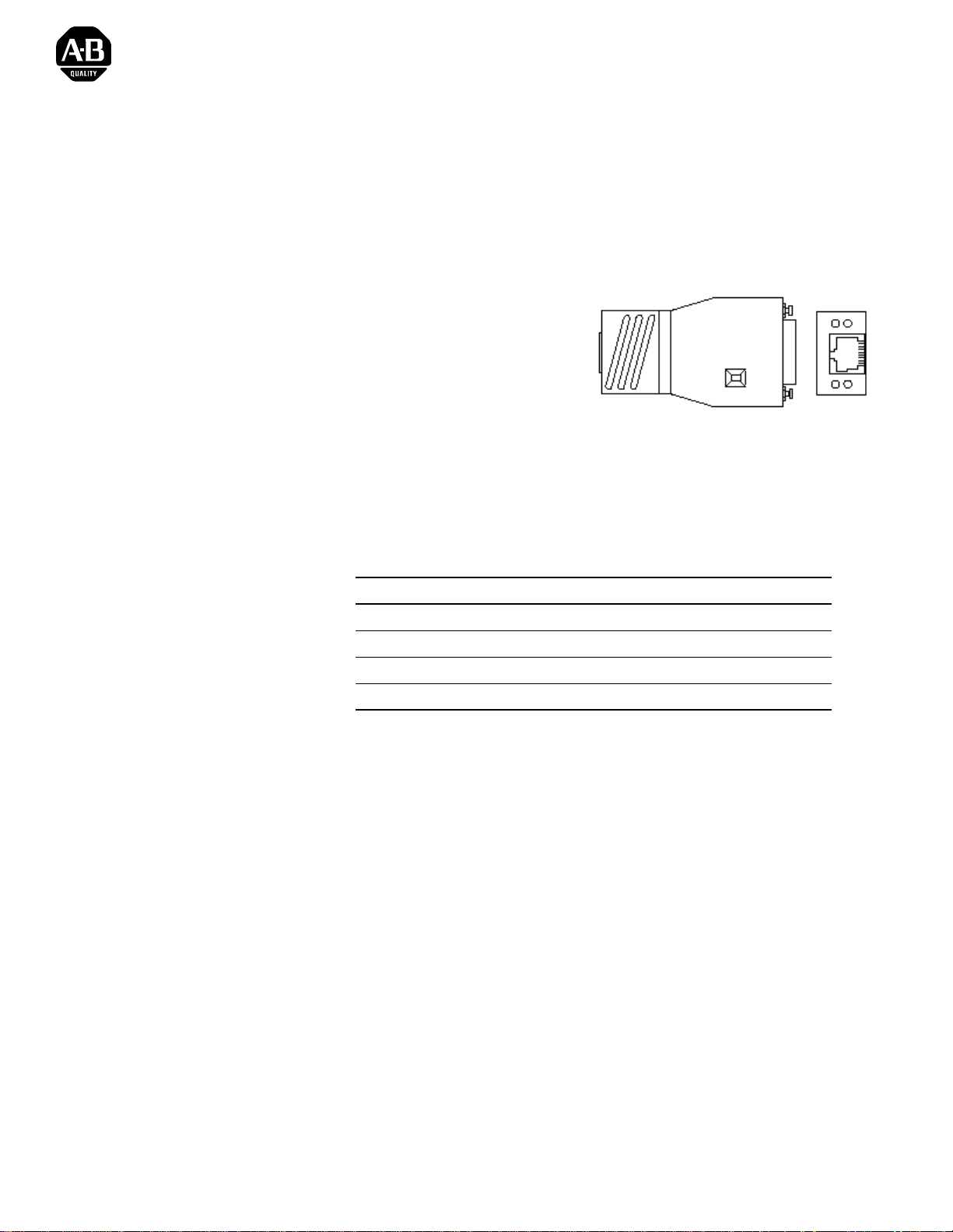
Twisted Pair Transceiver
Catalog Number 1785-TR10BT
The twisted pair transceiver enables a de vice with an AUI interface to
connect to a 10 Mbit/s CSMA/CD LAN (ISO/IEC 8802-3, IEEE 802.3,
10BASE-T) via a shielded twisted pair cable.
•
Monitoring LEDs for
– power
– collision/jabb er control/
TxData
– RxData
– link state/auto polarity
exchange
•
SQE test can be disabled externally
•
Can be plugged directly to the device interface
•
Low current consumption
•
Compact construction
To the Installer
Topic Pa ge
Description 2
Installation 3
Compliance to European Union Directives 4
Technical Data 7
1785-5.20 - January 1999
Page 2
2 Twisted Pair Transceiver
Description
The 1785-TR10BT twisted pair transceiver can be connected to the AUI
interface of a device either directly or via an AUI cable. It is connected to
the twisted pair cable by a 8-pin RJ45 socket.
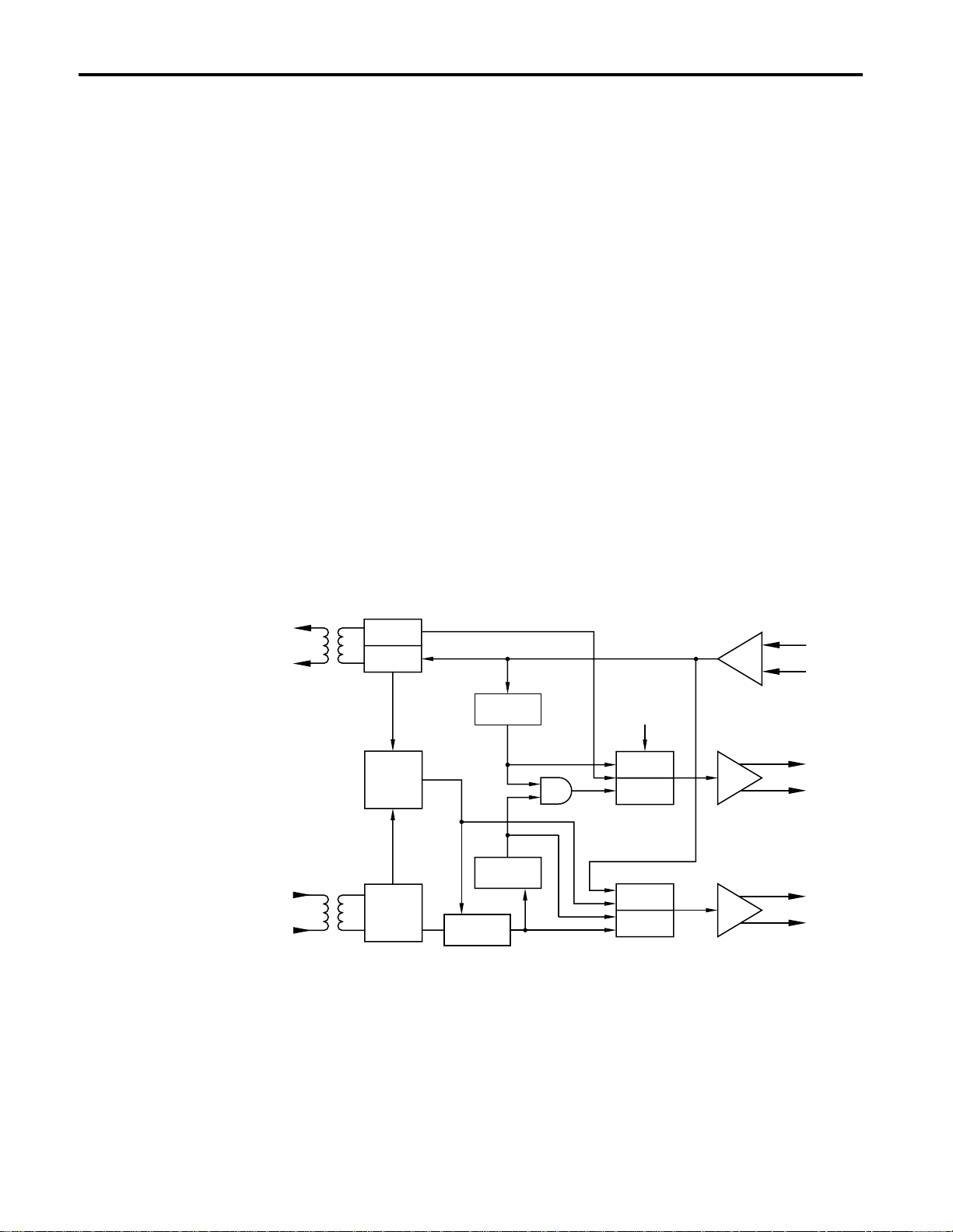
The twisted pair transceiver offers these functions according to IEEE 802.3
10BASE-T:
•
indication via a LED of data transmission and reception through the
twisted pair cable
•
detection of data collisions in the network and reporting them to the
terminal equipment as well as indicating them by a LED
•
ability to enable/disable the SQE test: at the end of every transmit
operation, a short collis ion signal ( heart beat) app rox. 1 µs long is sent to
monitor the electronics
•
jabber control and d ispla y: pr otect ing t he net work form d ata pa ckets that
are too long (> 20 ms)
•
link control and display: continious moni-toring the twisted pair cable
segment with link test pulses for short-circuits or idling
•
auto polarit y exchange (APX) and display: the polarity is reversed
automatically if the receiving wire pair is connected incorreclty (RD+
and RD- switched round)
10BASE-T Interface
Jabber
Protect
Tx-Data
Tx-Packet
Detect
Link
Status
Control
(RJ45 connector)
Rx-Packet
Detect
Rx-Data
Auto Polarity
Exchange
DISABLE
ENABLE
ENABLE/
DISABLE
SQE-Test
Generator
Collision
Osc.
Loopback
Data
Rx-Data
DO
CI
AUI Interface
(15-pin sub-D connector)
DI
1785-5.20 - January 1999
Page 3
Twisted Pair Transceiver 3
Installation
Link Attenuation
ISO/IEC 8802-3 (10BASE-T) specifies that the link attenuation of a single
cable segment must not exceed 11.5 dB at frequencies between 5 and 10
MHz (ZL = 100 Ω). This value includes
•
the attenuation of the twisted pair cable
•
connector attenuation
•
reflection attenuations as the result of adaption errors of the various
components belonging to the single cable segment, e.g., patch panels in
which twisted pair cables are connected to each other which, within the
scope of the tolerance, have differing characteristic impedance values at
the coupling point
Power Supply
The operating voltage (+12 V) is taken from the connected device via the
15-pin Sub-D socket of the AUI interface.
SQE Test
The slide switch on the top of the transceiver case is used to activate and
deactivate the SQE test. Before plac ing the trans ceiver in ope ration, you
should check to see whether the connected device requires the SQE test to
be on or off. As deli vered from the factory, the SQE test is on.
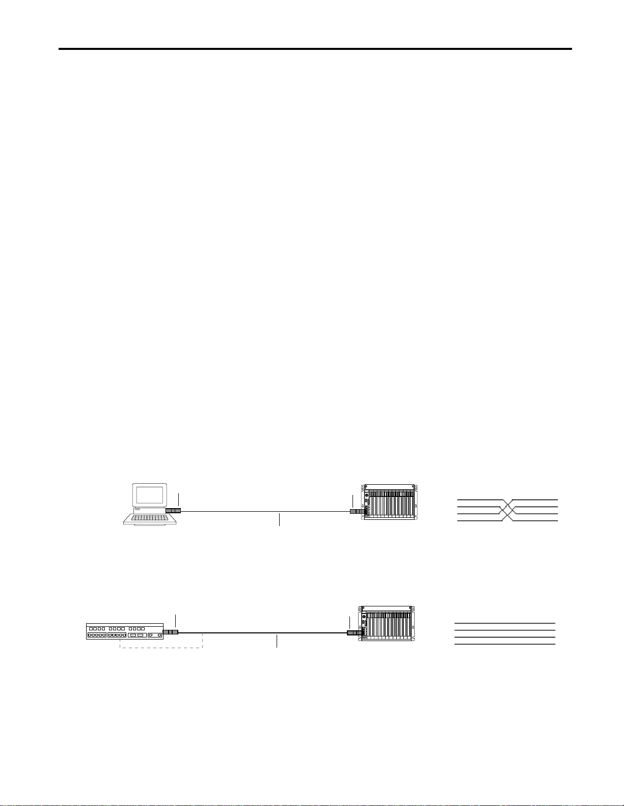
Connecting two devices
PC PLC5E
1785-TR10BT 1785-TR10BT
Twisted pair cable (100 Ω)
with RJ45 connectors
Connecting to an unshielded twisted pair interface card (hub, switch)
Hub
1785-TR10BT
or direct-connected to RJ45
Twisted pair cable (100 Ω)
with RJ45 connectors
1785-TR10BT
PLC5E
Pin assignments of the RJ45 to RJ45
connecting lead
RJ45 RJ45
1
2
3
6
Pin assignments of the RJ45 to RJ45
connecting lead
RJ45 RJ45
1
2
3
6
1
2
3
6
1
2
3
6
For Additional Information
For standards information, go to
copy of this publication, go to
http://www.theautomationbookstore.com/.
http://www.ieee.or g/. To download a .PDF
1785-5.20 - January 1999
Page 4

4 Twisted Pair Transceiver
Compliance to European Union Directives
If this product has the marking, it is approved for installation within the
European Union and EEA regions. It has been designed and tested to meet
the following directives.
EMC Directive
This product is tested to meet Council Directive 89/336/EEC
Electromagnetic Compatibility (EMC) and the following standard s, in
whole or in part, documented in a technical construction file:
•
EN 50081-2 EMC - Generic Emission Standard,
Part 2 - Industrial Environment
•
EN 50082-2 EMC - Generic Immunity Standard,
Part 2 - Industrial Environment
This product is intended for use in an industrial environment.
Low Voltage Directive
This product is tested to meet Council Directive 73/23/EEC Low Voltage,
by applying the safe ty req uir ements of EN 609 50 - In form ation Technology
Equipment.
For specific informat ion requi red by EN 60950 , see the ap propriat e section s
in this publication, as well as the following Allen-Bradley publicati ons:
•
Industrial Automation Wiring and Grounding Guidelines for Noise
Immunity, publication 1770-4.1
•
Automation Systems Catalog, publication B111
1785-5.20 - January 1999
Page 5

Twisted Pair Transceiver 5
Hazardous Location Approval
This product may be certified for general use as well as for use in hazardous locations. Actual agency
certification is indicated by the product label as shown below, and not by statements in any user
documentation.
Example of the certification product label:
CL I, DIV 2
GP A,B,C,D
TEMP
To comply with certification for use in hazardous locations, the following information becomes a part of the
product literature for this certified industrial control product.
• This equipment is suitable for use in Class I, Division 2, Groups A, B, C, D, or non-hazardous locations only.
• The products having the appropriate markings (that is, Class I, Division 2, Groups A, B, C, D) are certified for
use in other equipment where the suitability of combination (that is, application or use) is determined by the
local authority having jurisdiction.
Important: Due to the modular nature of a programmable control system, the product with the highest
temperature rating determines the overall temperature code rating of a programmable control system in a Class I,
Division 2, location. The temperature code rating is marked on the product label as shown.
Temperature code rating:
CL I, DIV 2
GP A,B,C,D
TEMP
/RRNIRUWHPSHUDWXUH
FRGHUDWLQJKHUH
The following warnings apply to products having certification for use in hazardous locations.
ATTENTION: Explosion hazard -
• Substitution of components may impair suitability for Class I, Division 2.
!
• Do not replace components unless power has been switched off or the area is known to be
non-hazardous.
• Do not disconnect equipment unless power has been switched off or the area is known to be
non-hazardous.
• Do not disconnect connectors unless power has been switched off or the area is known to be
non-hazardous. Secure any user-supplied connectors that mate to external circuits on this
equipment by using screws, sliding latches, threaded connectors, or other means such that
any connection can withstand a 15 Newton (3.4 lb.) separating force applied for a minimum of
one minute.
1785-5.20 - January 1999
Page 6

6 Twisted Pair Transceiver
Approbation d’utilisation en environnements dangereux
Ce produit est certifié pour une utilisation générale aussi bien que pour une utilisation en environnements
dangereux. La certification en vigueur est indiquée par l'étiquette produit et non par des indications dans la
documentation utilisateur.
Exemple d'étiquette de certification d'un produit :
Pour satisfaire à la certification en environnements dangereux, les informations suivantes font partie intégrante de
la documentation des produits de commande industrielle certifiés.
• Cet équipement ne convient qu’à une utilisation en environnements de Classe 1, Division 2, Groupes A, B, C, D,
ou non dangereux.
• Les produits portant le marquage approprié (c'est-à-dire, Classe 1, Division 2, Groupes A, B, C, D) sont
certifiés pour une utilisation avec d'autres équipements, les combinaisons d’applications et d’utilisation étant
déterminées par le bureau local d'inspection qualifié.
CL I, DIV 2
GP A,B,C,D
TEMP
Important : De par la nature modulaire des systèmes de commande programmables, le produit ayant le code de
température le plus élevé détermine le code de température global du système dans un environnement de
Classe 1, Division 2. Le code de température est indiqué sur l'étiquette produit.
Code de température
:
CL I, DIV 2
GP A,B,C,D
TEMP
Le code de température
est indiqué ici
Les avertissements suivants s'appliquent aux produits certifiés pour une utilisation en environnements dangereux.
DANGER : Risque d’explosion
• La substitution de composants peut rendre cet équipement inadapté à une utilisation en
!
environnement de Classe 1, Division 2.
• Couper le courant ou s’assurer que l’environnement est classé non dangereux avant de
remplacer des composants.
• Couper le courant ou s’assurer que l’environnement est classé non dangereux avant de
débrancher l’équipement.
• Couper le courant ou s’assurer que l’environnement est classé non dangereux avant de
débrancher les connecteurs. Fixer tous les connecteurs fournis par l’utilisateur pour se
brancher aux circuits externes de cet équipement à l’aide de vis, loquets coulissants,
connecteurs filetés ou autres, de sorte que les connexions résistent à une force de séparation
de 15 newtons (1,5 kg - 3,4 lb) appliquée pendant au moins une minute.
1785-5.20 - January 1999
Page 7

Technical Data
Twisted Pair Transceiver 7
Operating voltage +10 V to +16 V
Current consumption (no signal) 50 mA (+12 V)
Bit rate (Manchester Code) 10 Mbit/s
Dimensions W x H x D 45 mm x 21 mm x 81 mm
(1.8 in. x .83 in. x 3.2 in.)
Weight 100 g (0.22 lb.)
Ambient temperature 0° C to +50° C
Storage temperature –20° C to +80° C
Relative humidity 10 % to 90 % (non-condensing)
Twisted pair cable interface: Transmitter
Output signal on 100 Ω 5,4 VPP
Preamble loss transmit 1 bit
Steady State Delay 75 ns typ.
Jabber time out 80 ms
Jabber reset 500 ms
Twisted pair cable interface: Receiver
Input resistance 100 Ω at 5 MHz
Sesitivity 800 mVPP
Preamble loss receive 3 bit
Steady State Delay 75 ns typ.
Collision recognition time
(Data in › SQE out)
Transceiver interface (AUI)
Input:
Terminator
Sensitivity
Maximum DC component
Output:
Output voltage (Data and CD signal)
Frequency CD signal
SQE test (heart-beat)
Delay time
Length
AUI cable length
Insulation volatage
Transceiver interface/twisted pair cable
compliance with IEEE 802.3 10BASE-T
Pin assignment
Twisted pair interface
(RJ45 socket)
Transceiver interface
(15-pin sub-D plug)
300 ns
78 Ω ±1%
400 mVPP
± 50 V
1,4 VPP
10 MHz ± 10%
switchable on/off
1000 ns
1000 ns
0 to 50 m max.
1500 V ac from 50 to 60 Hz for 60 seconds
2250 V dc for 60 seconds
Transmit: TD+: Pin 1; TD–: Pin 2
Receive: RD+: Pin 3; RD–: Pin 6
Transmit: DO+: Pin 3; DO–: Pin 10
Receive: DI+: Pin 5; DI–: Pin 12
Collision detect: CI+: Pin 2; CI–: Pin 9
Power: GND: Pin 6; +12 V: Pin 13
Shield: Pin 1, 4, 8, 11, 14
1785-5.20 - January 1999
Page 8

Connections
Transceiver interface
Twisted pair interface
Connections capabilities
Transceiver interface
Twisted pair interface
Line attenuation
Displays
LINK
APX
TX-DA
CD
Conductors/Wire Size/Category
Agency Certification
(when product is marked)
P
RX-DA
15-pin sub-D plug
8-pin shielded RJ45 socket
plugged directly onto the AUI interface of connected
device or connected by an AUI cable (50 m max. length)
unshielded or shielded twisted pair cable segment
² 11,5 dB at 5-10 MHz (ZL = 100 Ω)
∗ green LED: P (Power)
on – supply voltage present
∗ green/red LED: Link/APX
off – Link status error
green – Link status ok
ret – Link status ok but polarity error, automatically
switched round of the polarity
∗ yellow/red LED: TX-DA/CD
yellow – transmitting data into the twisted pair cable
red, shortly on – Collision
red, continuous on – Jabber Control active
∗ yellow LED: RX-DA (Data)
on – receiving data from twisted pair cable
Category 2
CUS
1
• Information Technology Equipment
• Industrial Control Equipment
• Class I, Div. 2, Groups A, B. C, D
Hazardous Location
• EN 50082-1, 2
• EN 55022, Radiated Emission Class B
• EN 60950
FCC Part 15, SubPart B
1
Refer to the Industrial Automation Wiring and Grounding Guidelines for Noise Immunity, publication 1770-4.1.
Publication 1785-5.20 - January 1999 PN 955134-74
Copyright 1999 of Rockwell International Corporation. Printed in the U.S.A.
 Loading...