

Page 1
Installation Instructions
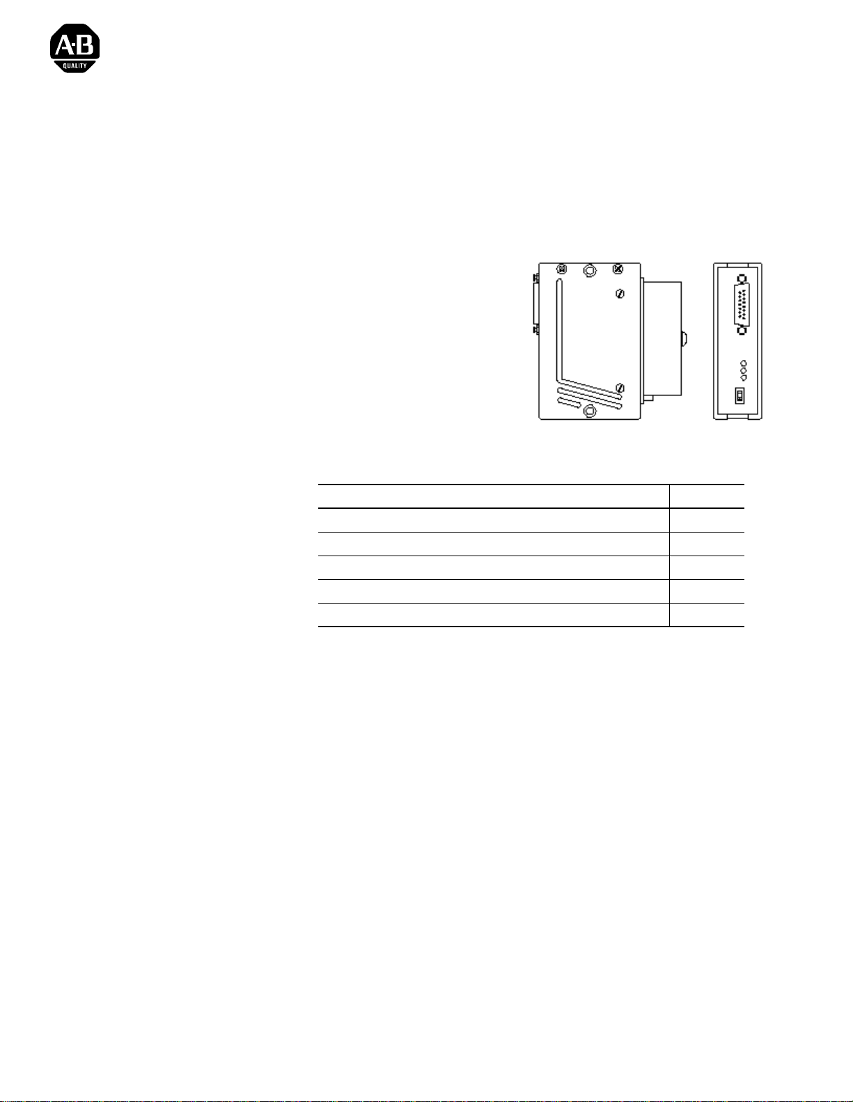
Coax Transceiver for 10BASE5
Catalog Number 1785-TR10B5
The coax transceive r lets you con nect a d evice wit h an AUI i nterface to a 10
Mbit/s CSMA/CD LAN (ISO/IEC 8802-3, IEEE 802.3, 10BASE5) coax
cable connection via this cable piercing tap.
•
Monitoring LEDs for
– power
– collision/jabb er control
– data
•
SQE test can be disabled
externally
•
Compact construction
To the Installer
Description
Topic Pa ge
Description 1
Installation 2
Coupling the Transceivers with the Coax Cable (10BASE5) 2
Compliance to European Union Directives 4
Technical Data 7
The 1785-TR10B5 coax transceiver can be connected to the AUI interface
of a device either directly or via an AUI cable. It is connected to the coax
cable by a coax interface.
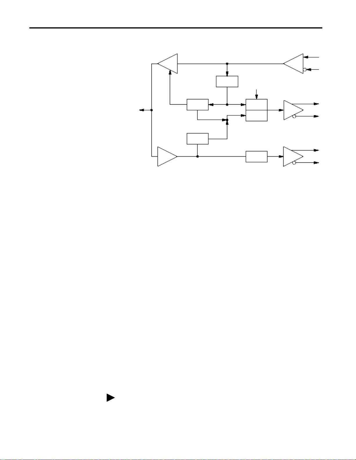
The transceiver offers these functions according to IEEE 802.3 10BASE5:
• receiving the data at the transceiver interface and sending them into the
coax cable
• receiving the data from the coax cable and sending them to the
transceiver interface
• indication via a yellow LED of data transmission and reception through
the coax cable
• detection of data collisions in the network and reporting them to the
terminal equipment as well as indicating them by a red LED
• ability to enable/disable the SQE test: at the end of every transmit
operation, a short collis ion signal ( heart beat) app rox. 1 µs long is sent to
monitor the electronics
• jabber control and display: prote cting the network fr om data packe ts t hat
are too long (> 20 ms)
1785-5.17 - January 1999
Page 2
2 Coax Transceiver for 10BASE5
Installation
DO
CI
DI
Coax
cable
TX
TX Packet
Detect
Jabber
Protect
Collision
Detect
RX
ENABLE/
DISABLE
SQE-Test
Generator
Collision
Osc.
RX-Data
SQE Test
The slide switch located beside the three control LEDs is used to activate
and deactivate the SQE test.
Important:Before placing the transceiver in operat ion, you shoul d check to
see whether the conn ected dev ice requ ires th e SQE test to be on
or off.
Coupling the Transceivers with the Coax Cable (10BASE5)
Power Supply
The operating voltage (+12 V) is taken from the connected device via the
15-pin Sub-D socket of the AUI interface.
1785-TR10B5 with cable piercing tap
The vampire ter minal consists of these single items :
• 1 top section
• 1 socket-head cap screw
• 1 bottom section
• 2 contact springs
• 1 contact needle
The distance between two transceivers fitted on the same coax segment
must be at least 2.5 meters.
1785-5.17 - January 1999
Page 3
Coax Transceiver for 10BASE5 3
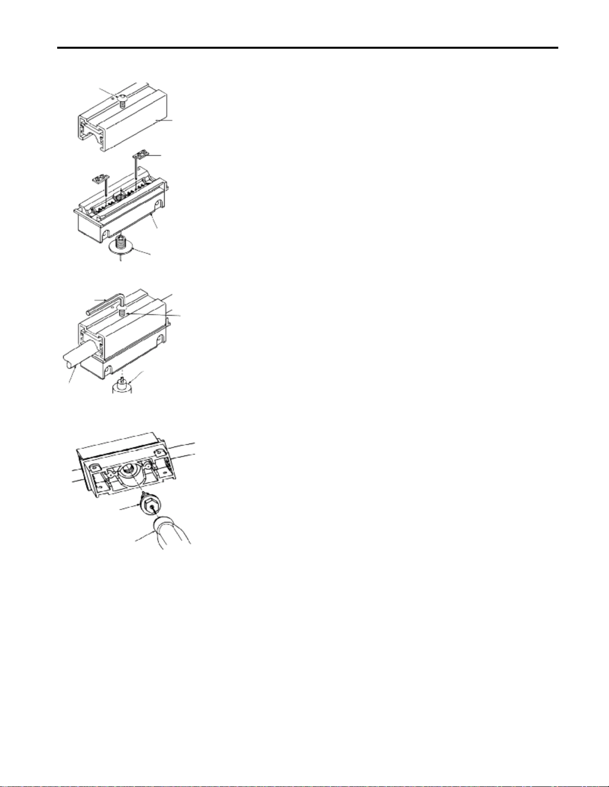
socket-head
cap screw
socket
spanner
top section
contact spring
bottom section
contact needle
socket-head
cap screw
drill
Assembly
1. As shown in the figure, i nsert the two contact springs in the bot tom part.
Do not screw in the contact needle.
2. Determine the required coupling point on the coax cable.
3. Place the coax cable in the bottom section.
4. Push the top section onto the bottom section.
5. Screw the socket-head cap screw into the top section using the socket
spanner, and tighten it.
6. Drill into th e cable with the drill of the combination tool.
Important:Drill cleanly, i.e.:
no protruding wires of the cable shield visible in the drill hole (risk of
–
short-circuit)
– drill hole penetrates the braiding and foil of the shield so that the
dielectric of the cable (plastic layer between centre conductor and
shield) is visible
coax cable
(10BASE5)
contact needle
hexagon screw key
7. If it is not possible to drill deeply enough, tighten the socket-head cap
screw further.
Important:Tighten the screw gently!
8. Screw in the contact needle using the hexagon screw key of the
combination tool.
9. Insert the pre-assembled vampire terminal in the housing of the
1785-TR10B5 until it bottoms and secure it with the M3 screws
included.
For Additional Information
For standards information, go to
copy of this publication, go to
http://www.ieee.org/. To download a .PDF
http://www.theautomationbookstore.com/.
1785-5.17 - January 1999
Page 4

4 Coax Transceiver for 10BASE5
Compliance to European Union Directives
If this product has the marking, it is approved for installation within the
European Union and EEA regions. It has been designed and tested to meet
the following directives.
EMC Directive
This product is tested to meet Council Directive 89/336/EEC
Electromagnetic Compatibility (EMC) and the following standard s, in
whole or in part, documented in a technical construction file:
•
EN 50081-2 EMC - Generic Emission Standard,
Part 2 - Industrial Environment
•
EN 50082-2 EMC - Generic Immunity Standard,
Part 2 - Industrial Environment
This product is intended for use in an industrial environment.
Low Voltage Directive
This product is tested to meet Council Directive 73/23/EEC Low Voltage,
by applying the safe ty req uir ements of EN 609 50 - In form ation Technology
Equipment.
For specific informat ion requi red by EN 60950 , see the ap propriat e section s
in this publication, as well as the following Allen-Bradley publicati ons:
•
Industrial Automation Wiring and Grounding Guidelines for Noise
Immunity, publication 1770-4.1
•
Automation Systems Catalog, publication B111
1785-5.17 - January 1999
Page 5

Coax Transceiver for 10BASE5 5
Hazardous Location Approval
This product may be certified for general use as well as for use in hazardous locations. Actual agency
certification is indicated by the product label as shown below, and not by statements in any user
documentation.
Example of the certification product label:
CL I, DIV 2
GP A,B,C,D
TEMP
To comply with certification for use in hazardous locations, the following information becomes a part of the
product literature for this certified industrial control product.
• This equipment is suitable for use in Class I, Division 2, Groups A, B, C, D, or non-hazardous locations only.
• The products having the appropriate markings (that is, Class I, Division 2, Groups A, B, C, D) are certified for
use in other equipment where the suitability of combination (that is, application or use) is determined by the
local authority having jurisdiction.
Important: Due to the modular nature of a programmable control system, the product with the highest
temperature rating determines the overall temperature code rating of a programmable control system in a Class I,
Division 2, location. The temperature code rating is marked on the product label as shown.
Temperature code rating:
CL I, DIV 2
GP A,B,C,D
TEMP
/RRNIRUWHPSHUDWXUH
FRGHUDWLQJKHUH
The following warnings apply to products having certification for use in hazardous locations.
ATTENTION: Explosion hazard -
• Substitution of components may impair suitability for Class I, Division 2.
!
• Do not replace components unless power has been switched off or the area is known to be
non-hazardous.
• Do not disconnect equipment unless power has been switched off or the area is known to be
non-hazardous.
• Do not disconnect connectors unless power has been switched off or the area is known to be
non-hazardous. Secure any user-supplied connectors that mate to external circuits on this
equipment by using screws, sliding latches, threaded connectors, or other means such that
any connection can withstand a 15 Newton (3.4 lb.) separating force applied for a minimum of
one minute.
1785-5.17 - January 1999
Page 6

6 Coax Transceiver for 10BASE5
Approbation d’utilisation en environnements dangereux
Ce produit est certifié pour une utilisation générale aussi bien que pour une utilisation en environnements
dangereux. La certification en vigueur est indiquée par l'étiquette produit et non par des indications dans la
documentation utilisateur.
Exemple d'étiquette de certification d'un produit :
Pour satisfaire à la certification en environnements dangereux, les informations suivantes font partie intégrante de
la documentation des produits de commande industrielle certifiés.
• Cet équipement ne convient qu’à une utilisation en environnements de Classe 1, Division 2, Groupes A, B, C, D,
ou non dangereux.
• Les produits portant le marquage approprié (c'est-à-dire, Classe 1, Division 2, Groupes A, B, C, D) sont
certifiés pour une utilisation avec d'autres équipements, les combinaisons d’applications et d’utilisation étant
déterminées par le bureau local d'inspection qualifié.
CL I, DIV 2
GP A,B,C,D
TEMP
Important : De par la nature modulaire des systèmes de commande programmables, le produit ayant le code de
température le plus élevé détermine le code de température global du système dans un environnement de
Classe 1, Division 2. Le code de température est indiqué sur l'étiquette produit.
Code de température
:
CL I, DIV 2
GP A,B,C,D
TEMP
Le code de température
est indiqué ici
Les avertissements suivants s'appliquent aux produits certifiés pour une utilisation en environnements dangereux.
DANGER : Risque d’explosion
• La substitution de composants peut rendre cet équipement inadapté à une utilisation en
!
environnement de Classe 1, Division 2.
• Couper le courant ou s’assurer que l’environnement est classé non dangereux avant de
remplacer des composants.
• Couper le courant ou s’assurer que l’environnement est classé non dangereux avant de
débrancher l’équipement.
• Couper le courant ou s’assurer que l’environnement est classé non dangereux avant de
débrancher les connecteurs. Fixer tous les connecteurs fournis par l’utilisateur pour se
brancher aux circuits externes de cet équipement à l’aide de vis, loquets coulissants,
connecteurs filetés ou autres, de sorte que les connexions résistent à une force de séparation
de 15 newtons (1,5 kg - 3,4 lb) appliquée pendant au moins une minute.
1785-5.17 - January 1999
Page 7

Technical Data
Coax Transceiver for 10BASE5 7
Operating Voltage +10 to +16 V
Current consumption (no signal) 250 mA
Bit rate (Manchester Code) 10 Mbit/s
Dimensions W x H x D 92 mm x 32.5 mm x 100 mm
(3.6 in. x 1.3 in. x 3.9 in.)
Weight 480 g (1.06 lb.)
Ambient temperature 0° C to 50° C
Storage temperature –25° C to +85° C
Relative humidity 10% to 90% (non condensing)
Coax cable interface (MDI): Transmitter
Output signal:
AC
DC
Rise/fall time
Harmonic components:
1st harmonic
2nd harmonic
3rd harmonic
4th harmonic
5th harmonic
6th harmonic
7th harmonic and higher
Preamble loss transmit less than or equal to 2 bit
Stady State Delay 15 ns
Jabber time out 25 ms
Jabber reset 500 ms
Coax cable interface (MDI): Receiver
Coax cable input current 5 µA
Capacitive load 2 pF
Input resistance > 100 kΩ
Noise suppression –250 mV
Preamble loss receive 1 bit (3 bit max.)
Steady State Delay 10 ns
Collision Detect threshold –1,6 V
1,9 V +0,35 V, –0,5 V
–1,025 V ±0,1 V
25 ns ±20%
–34 dB
–23 dB
–40 dB
–39 dB
–40 dB
–47 dB
–55 dB
Transceiver interface (AUI)
Input:
Terminating resistance
Sensitivity
Maximum DC component
Output:
Output voltage (Data and CD signal)
CD signal frequency
SQE test (heart beat)
delay time
length
AUI cable length 50 m max.
78 Ω ±1%
400 mV PP
±50 V
1,4 V PP
10 MHz ±20%
switchable
1000 ns
800 ns
1785-5.17 - January 1999
Page 8

Insulation voltage
Transceiver interface/coax cable
Insulation resistance:
at 50/60 Hz
at 3 MHz
Pin assignment
Transceiver interface
Connections:
Transceiver interface
Coax cable interface
Displays
Conductors/Wire Size/Category
Agency Certification
(when product is marked)
2000 V dc
500 kΩ
15 Ω
Transmit:DO + : Pin 3; DO – : Pin 10
Receive:DI + : Pin 5; DI – : Pin12
Collision Detect:CI + : Pin 2; CI – : Pin 9
Power:GND: Pin 6; +12 V: Pin 13
Chassis/Shield:Pin 1, 4, 8, 11, 14
15-pin Sub-D plug
1785-TR10B5: cable piercing tap
* green LED: P (Power) – Supply voltage present
* red LED: CD (Collision Detection)
DACDP
shortly on – Collision
continuous on – Jabber Control active
* yellow LED: DA (Data) – Sending or receiving data
Category 2
CUS
1
• Information Technology Equipment
• Industrial Control Equipment
• Class I, Div. 2, Groups A, B. C, D
Hazardous Location
• EN 50082-1, 2
• EN 55022, Radiated Emission Class B
• EN 60950
FCC Part 15, SubPart B
1
Refer to the Industrial Automation Wiring and Grounding Guidelines for Noise Immunity, publication 1770-4.1.
Publication 1785-5.17 - January 1999 PN 955134-71
Copyright 1999 of Rockwell International Corporation. Printed in the U.S.A.
 Loading...