

Page 1
Enhanced PLC5 and Ethernet PLC5
Programmable Controller
Memory Module
(Cat. No. 1785-ME16, -ME32, -ME64, and -M100)
Installation Data
To the Installer
Terminology
This document provides you with the following information.
For information about: Go to page:
European Union directive compliance 2
choosing compatible processors and software for the memory module 3
handling the memory module 3
setting backplane switches 4
installing the memory module 5
removing the memory module 5
using the write protection jumper 5
writing to the memory module 6
handling an error while writing to the memory module 8
restoring a program from a memory module 8
specifications 9
These processors are referred to as enhanced PLC-5
programmable controllers:
PLC-5/11
PLC-5/20
PLC-5/30
PLC-5/40, -5/40L
PLC-5/60, -5/60L
PLC-5/80
These processors are referred to as Ethernet PLC-5
programmable controllers:
PLC-5/20E
PLC-5/40E
PLC-5/80E
Page 2

Installation Data
Installation Data
PLC5/11, 5/20, 5/30, 5/40, 5/40L, 5/60
Enhanced PLC5 and Ethernet PLC5
Programmable Controller Memory Module
Programmable Controller Memory Module
European Union Directive Compliance
If this product is installed within the European Union or EEA regions and
the product has a CE mark, the following regulations apply.
EMC Directive
This apparatus is tested to meet Council Directive 89/336 Electromagnetic
Compatibility (EMC):
EN 50081-2 EMC – Generic Emission Standard, Part 2 – Industrial
Environment
EN 50082-2 EMC – Generic Immunity Standard, Part 2 – Industrial
Environment
According to these Standards, the factor which determines, for EMC
purposes, whether an apparatus is deemed to be “Industrial” or “Residential,
commercial and light industrial“, is given in Clause 1 of EN50081-2 as
follows:
Apparatus covered by this standard is not intended for connection
to a public mains network but is intended to be connected to a
power network supplied from a high- or medium-voltage
transformer dedicated for the supply of an installation feeding a
manufacturing or similar plant.
The product described in this manual is intended for use solely in an
industrial environment as defined above. When installed in Europe, any
other application is in contravention of European Union Directives, and a
breach of those laws.
Low Voltage Directive
This apparatus is also designed to meet Council Directive 73/23 Low
Voltage, by applying the safety requirements of EN 61131–2 Programmable
Controllers, Part 2 – Equipment Requirements and Tests.
For specific information that the above norm requires, see the appropriate
sections in this manual, as well as the following Allen-Bradley publications:
Industrial Automation Wiring and Grounding Guidelines, publication
1770-4.1
Guidelines for Handling Lithium Batteries, publication AG-5.4
Automation Systems Catalog, publication B111
2
Page 3
Installation Data
Enhanced PLC5 and Ethernet PLC5
Programmable Controller Memory Module
Choosing Compatible Processors and Software for the Memory Module
Memory Module: Compatible Programmable Controllers: Compatible Software:
1785ME16,
1785ME32 and
1785M100
1785ME64 1785L11B, L20B, L30B
1785L11B, L20B, L30B, L40B, L40L, L60B, L60L,
1785L11B, L20B
1785L20E, 1785L40E
1785L30B
1785L40B, L40L, L60B, L60L
1785L40B, L40L, L60B, L60L
1785L80B
1785L20E, 1785L40E
1785L40B, L60B
1785L40L, L60L
1785L80B
Table 1 shows the the programmable controllers and the software that are
compatible with the 1785-ME16, -ME32, -ME64, -M100
memory modules.
Table 1
1785ME16,
ME32, ME64, M100 Compatibility
Catalog Number: Series and Revision:
series C, revision C and later
series A, revision E and later
series C, revision D and later
series A revision F and later
series B revision F and later
series A, revision J and later
series C, revision C and later
all series, all revisions
series C, revision D and later
series A, revision C and later
series A, revision C and later
series C, revision C and later
6200 PLC5
Programming Software
release 4.4 or later
6200 PLC5
Programming Software
release 4.1 or later
Handling the Memory Module
The memory module is shipped in a static-shielded bag to guard against
electrostatic damage.
ATTENTION: Under some conditions, electrostatic discharge
can degrade performance or damage the memory module.
Observe the following precautions to guard against
electrostatic damage:
Touch a grounded object to rid yourself of static charge
before handling the module.
When not in use, keep the module in its static-shielded bag.
3
Page 4

Installation Data
Installation Data
PLC5/11, 5/20, 5/30, 5/40, 5/40L, 5/60
Enhanced PLC5 and Ethernet PLC5
Programmable Controller Memory Module
Programmable Controller Memory Module
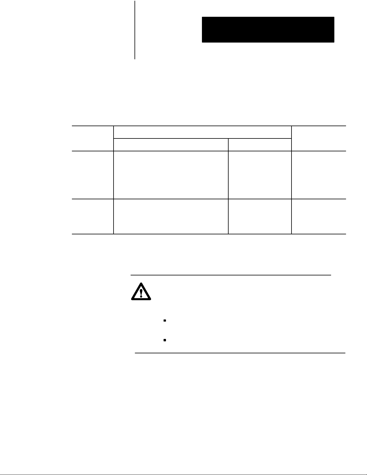
Setting Backplane Switches
If you want the contents of the memory module: Then set switch 6: And set switch 7:
to transfer to processor memory at every powerup OFF OFF
to transfer to processor memory when a defect is detected in existing
processor memory
not to transfer to processor memory at powerup; if the processor
memory is not valid, a processor fault occurs.
Set the I/O chassis backplane switches before you install the PLC-5
processor. Use a ballpoint pen to set each switch (do not use a pencil
because the tip can break off and short the switch).
ON (Closed)
OFF (Open)
Backplane
switches
Backplane
Switches
18594
Use Table 2 to select the mode of memory transfer at power-up.
Table 2
Selecting
Mode of Memory Transfer and Switch Settings
ON ON
ON OFF
4
Page 5

Installation Data
Enhanced PLC5 and Ethernet PLC5
Programmable Controller Memory Module
Installing the Memory Module
Keying pin
Removing the Memory Module
Insert the memory module into the front of the PLC-5 processor by
following these steps:
1. Turn off power to the I/O chassis and processor.
ATTENTION: Do not insert or remove the memory module
under power. Insertion or removal under power can result in
loss of program memory and a processor fault.
2. Insert the memory module firmly but gently into the processor with
the keying pin in the down position. When the memory module is
inserted correctly you will hear the connector pins on the back of the
memory module snap together with the mating connector in
the processor.
18590
Remove the memory module by following these steps:
1. Turn off power to the I/O chassis and processor.
Keying pin
Using the Write Protection Jumper
Write protection
jumper
18592
ATTENTION: Do not insert or remove the memory module
under power. Insertion or removal under power can result in
loss of program memory and a processor fault.
2. Grasp the finger grip tabs and firmly pull the memory module out of
the processor.
18591
The write protection jumper allows you to program the memory module.
The memory module is packaged with the jumper in the correct position to
write to the memory module.
After writing to the memory module, remove the write protection jumper
using a pair of needle nose pliers. Store the jumper in a safe place for
future use. Once you remove the jumper, you cannot write to the
memory module.
5
Page 6

Installation Data
Installation Data
PLC5/11, 5/20, 5/30, 5/40, 5/40L, 5/60
Enhanced PLC5 and Ethernet PLC5
Programmable Controller Memory Module
Programmable Controller Memory Module
Writing to the Memory Module
Card Guides
Locking
Bar
Ejector
Ta b
PLC5
processor
19632
Use the following steps to store a program on your memory module.
Important: If you are using a 1785-L40B series A, revision B or a
1785-L60B series A, revision B processor, you must have the Global
Status Flag file set to zero. Access this file through the channel
configuration screen for channels configured for DH+ communications. If
the Global Status Flag file is set to any number except zero and you try to
write to a memory module, you will lose processor memory and a
processor fault occurs.
1. Insert the memory module into the processor using the installation
procedure in this document (see page 5).
2. On the I/O chassis backplane, set backplane switch 6 to the ON
position and switch 7 to the OFF position (see page 4).
3. Install the processor into the I/O chassis.
4. Turn on power to the processor and I/O chassis.
5. Put the processor in Program or Rem Program mode.
18593
If you try to write to a memory module when the processor is in any
other mode, you receive a
NO ACCESS OR PRIVILEGE
VIOLATION message.
6. Develop or download your program online (make sure you initialize
your data table values).
6
Page 7

Ladder Editor
Main Menu
General Utilities
F7
General
Utility screen
W
rite EEPROM
F7
Installation Data
Enhanced PLC5 and Ethernet PLC5
Programmable Controller Memory Module
7. Transfer a duplicate of your program to the memory module. You
must be programming online to write to a memory module (use the
figure below).
| I:001 O:005 |
+––]/[––––––––––––––––––––––––––––––––––––––––––––––––––––––––––––––––––( )––+
| 14 10 |
| +TON–––––––––––––––+ |
+––––––––––––––––––––––––––––––––––––––––––––––––––+TIMER ON DELAY +–(EN)–+
| |Timer T4:0| |
| |Time base 0.01+–(DN) |
| |Preset 12| |
| |Accum 0| |
| +––––––––––––––––––+ |
| +MSG––––––––––––––––––––+ |
+–––––––––––––––––––––––––––––––––––––––––––––+SEND/REC MESSAGE +–(EN)–+
| |Control Block N7:10+–(DN) |
| | +–(ER) |
| +–––––––––––––––––––––––+
+––––––––––––––––––––––––––––––[END OF FILE]–––––––––––––––––––––––––––––––––+
Press a function key.
(file 2, rung 3)
Rem Prog Forces:None Edits:None 5/40 Addr 25 LIMIT
Change Config Return Program Documnt Search General Data Force Edit
Mode Display to Menu Dirctry Utility Monitor
F1 F2 F3 F4 F5 F6 F7 F8 F9 F10
[Y] [Enter] or [F8] - Yes
[N] [Enter] or [F10] - No
If you confirm the procedure, the memory module write begins.
During this procedure, the “PROC” LED on the processor
flashes green and the programming terminal beeps until the
write procedure is completed.
If no error occurs during the write to the memory module, you
see the following message displayed: EEPROM
SUCCESSFULLY
BURNED
8. Remove the memory module from the processor using the removal
procedure in this document (see page 5).
9. Label the memory module with a ballpoint pen. Use the space
provided to label the program transferred to the memory module.
18595
7
Page 8

Installation Data
Installation Data
PLC5/11, 5/20, 5/30, 5/40, 5/40L, 5/60
Enhanced PLC5 and Ethernet PLC5
Programmable Controller Memory Module
Programmable Controller Memory Module
Handling an Error while Writing to the Memory Module
Restoring a Program from a Memory Module
If an error occurs during a write to the memory module, you see this
message displayed: EEPROM
NOT BURNED
If you get this message, do the following:
check that you inserted the write protect jumper
check minor fault bit (S:10/8) in the status file. If this bit is set, then
there is not enough memory on your memory module to upload the
program from the processor.
review the “Writing to the Memory Module” procedure (see page 6)
and repeat it from the beginning
You can restore a program from a memory module to the processor
memory using the following procedure.
If the restore fails, the old program remains in memory and the EEPROM
transfer bit (minor fault bit S:10/3) is cleared.
Important: When restoring a program from a memory module using a
1785-L40B series A, revision B or a 1785-L60B series A, revision B
processor, the memory module overwrites the DH+ station address for
channel 1A.
Card Guides
Locking
Bar
19633
Ejector
Ta b
PLC5
processor
1. Turn off power to I/O chassis and processor.
2. Remove the processor from the I/O chassis.
3. Set backplane switch 6 and 7 of the switch assembly group to the
OFF position (see page 4). This allows the memory module
memory to transfer to processor memory at power-up.
4. Install the processor into the I/O chassis.
5. Install the memory module containing the program to be restored into
the processor using the installation procedure in this document (see
page 5).
6. Turn on power to the processor. Program transfer and execution
begin immediately with the processor keyswitch in Run or
Rem position.
8
Page 9

Locking
Bar
Ejector
Ta b
Installation Data
Enhanced PLC5 and Ethernet PLC5
Programmable Controller Memory Module
Important: You can have continuous processor memory backup after
restoring a program from a memory module to a processor by following
these instructions:
1. Turn off power to the processor and I/O chassis.
2. Remove the memory module by following the removal procedure in
this document (see page 5).
3. Remove the write protection jumper with needle nose pliers to guard
against unauthorized changes. Store the jumper in a safe place for
future use.
4. Re-install the memory module into the processor by following the
installation procedure in this document (see page 5).
5. Remove the processor from the I/O chassis.
Card Guides
Specifications
PLC5
processor
19633
6. Set switch 6 and 7 of the assembly backplane switches to the ON
position (see page 4).
7. Re-install the processor into the I/O chassis.
The following table shows the specifications for the memory modules.
Memory Module 1785ME16 1785ME32 1785ME64 1785M100
Capacity 16K words 32K words 64K words 100K words
Type Nonvolatile
Write Protection By removing the jumper
Weight 85.05 g
3 oz
Environment
Shock Testing
Operating Temperature
Storage Temperature
Relative Humidity 5 to 95% (without condensation)
Operating 15 g peak acceleration at 11 ms duration
0° to 60° C (32° to 140° F)
40° to 85° C (40° to 185° F)
70.875 g
2.5 oz
70.875 g
2.5 oz
70.875 g
2.5 oz
Nonoperating 3 g peak acceleration at 11 ms duration
Vibration Testing 2 g peak acceleration at 10500 Hz
Agency Certification
(when product or package is marked)
• CSA certified
• CSA Class I, Division 2
Groups A, B, C, D
• UL listed
• CE marked for all applicable directives
9
Page 10

Installation Data
Installation Data
PLC5/11, 5/20, 5/30, 5/40, 5/40L, 5/60
Enhanced PLC5 and Ethernet PLC5
Programmable Controller Memory Module
Programmable Controller Memory Module
AllenBradley, a Rockwell Automation Business, has been helping its customers improve
productivity and quality for more than 90 years. We design, manufacture and support a broad
range of automation products worldwide. They include logic processors, power and motion
control devices, operator interfaces, sensors and a variety of software. Rockwell is one of the
worlds leading technology companies.
Worldwide representation.
Argentina •
Denmark • Ecuador
Ireland
Philippines •
Sweden
AllenBradley Headquarters, 1201 South Second Street, Milwaukee, WI 53204 USA, Tel: (1) 414 3822000 Fax: (1) 414 3824444
Publication
Supercedes
10
Australia • Austria • Bahrain
• Israel • Italy • Jamaica •
• Switzerland • T
17855.10 September 1995
Publication 17852.1
• Egypt • El Salvador • Finland • France •
Poland • Portugal • Puerto Rico • Qatar • Romania • Russia-CIS • Saudi Arabia • Singapore
aiwan
1 Septemebr 1993
• Belgium • Brazil •
Japan • Jordan • Korea • Kuwait • Lebanon
• Thailand • T
urkey • United Arab Emirates • United Kingdom • United States • Uruguay
Bulgaria • Canada
Germany • Greece • Guatemala • Honduras • Hong Kong • Hungary
• Chile •
• Malaysia • Mexico •
China, PRC • Colombia
Netherlands
• Slovakia • Slovenia •
• Costa Rica •
• New Zealand •
• V
enezuela
Croatia • Cyprus
• Iceland •
Norway
South Africa, Republic
• Yugoslavia
Copyright
• Czech Republic •
India • Indonesia
• Pakistan •
1995 AllenBradley Company
Peru
•
• Spain •
PN
95512330
, Inc. Printed in USA
•
 Loading...