

Page 1

PLC-5 Protected Processors
(Cat. No. 1785-L26B, -L46B, and -L86B)
Supplement
Page 2
Important User Information
Because of the variety of uses for the products described in this publication,
those responsible for the application and use of this control equipment must
satisfy themselves that all necessary steps have been taken to assure that each
application and use meets all performance and safety requirements, including
any applicable laws, regulations, codes, and standards.
The illustrations, charts, sample programs and layout examples shown in this
guide are intended solely for purposes of example. Since there are many
variables and requirements associated with any particular installation,
Allen-Bradley does not assume responsibility or liability (to include
intellectual property liability) for actual use based on the examples shown
in this publication.
Allen-Bradley publication SGI-1.1, Safety Guidelines for the Application,
Installation, and Maintenance of Solid-State Control (available from your
local Allen-Bradley office), describes some important differences between
solid-state equipment and electromechanical devices that should be taken
into consideration when applying products such as those described in this
publication.
Reproduction of the contents of this copyrighted publication, in whole or in
part, without written permission of Allen-Bradley Company, Inc., is prohibited.
Throughout this manual, we use notes to make you aware of safety
considerations:
ATTENTION: Identifies information about practices or
circumstances that can lead to personal injury or death,
property damage or economic loss.
Attention statements help you to:
identify a hazard
avoid the hazard
recognize the consequences
Important: Identifies information that is critical for successful application
and understanding of the product.
Data Highway Plus, DH+, PLC-5/11, PLC-5/20, PLC–5/20E, PLC-5/26, PLC-5/30, PLC-5/V30,
PLC-5/40, PLC-5/40E, PLC-5/40L, PLC-5/V40, PLC-5/V40L, PLC-5/46, PLC-5/60, PLC-5/60L,
PLC-5/80, PLC-5/80E, PLC-5/86, and PLC-5/250 are trademarks of Allen-Bradley Company, Inc.
PLC and PLC-5 are registered trademarks of Allen-Bradley Company, Inc.
Page 3

Using This Supplement
Preface
Introduction
Audience
Contents
This supplement describes how to use the security features provided
by a PLC-5/26t, PLC-5/46t, or PLC-5/86t protected processor.
The information in this supplement is intended primarily for the
system administrator—a user with unique privileges who can
control access to critical areas of the protected processor’s program.
End users—operators with restricted access to the processor’s program
—can also benefit from reading this supplement.
You should be an engineer or technician with a background in
control-system application, and you should be familiar with:
• programmable real-time control systems
• the PLC-5
• your operation’s basic security requirements
If you want to read about: See chapter:
Planning for a protected system
Configuring passwords and privileges 2
Configuring and using data-table element protection 3
R
control system
1
Terminology
Term Definition
DTEP
End user User of a protected processor who, typically, cannot modify privileges or passwords and therefore
Class One of four administrator-defined groups of privileges allowing a user to perform specific processor
Screened command Communications command used in the interface between the processor and the programming
System administrator User of a protected processor who, typically, can modify privileges and passwords and therefore
Privilege
Data-table element protection
does not have the authority to override the DTEP provided by the processor
command operations; each class is accessed by an administrator-assigned password
software that is screened for violations of the protection mechanisms provided by the PLC-5
protected processor
does have the authority to override the DTEP provided by the processor
Ability to perform a command operation supported by the PLC-5 protected processor, including any
of the following:
• modify privileges
• data-table file create/delete
• program file create/delete
• logical write
• physical write
• logical read
• physical read
• mode change
• I/O force
• sequential function chart (SFC) force
• clear memory
• restore
• online edit
i
Page 4

Preface
Using
This Supplement
Related Publications
1785 Enhanced
PLC-5 Processor
System Overview
Overview of processor
functionality, system
benefits, and
operating features
1785-2.36
Enhanced & Ethernet PLC-5
Programmable Controllers
User Manual
How to configure,
program, and operate
your processor
1785-6.5.12
PLC-5
Programming Software
Programming
Creating/managing files,
saving/restoring files,
importing/exporting files
creating/editing SFCs,
creating/editing ladder
The 1785 PLC-5 Programmable Controller documentation is organized into
manuals according to the tasks that you perform.
1785 PLC-5
Programmable Controllers
Design Manual
Explanation of processor
functionality, system
design, and programming
considerations
1785-6.2.1
1785 PLC-5
Programmable Controllers
Quick Reference
Quick access to switches,
status bits, indicators,
instructions, SW screens
1785-7.1
PLC-5
Programming Software
Software Configuration
and Maintenance
Installing software, defining
data-table files, configuring
processor, checking status,
clearing faults
1785 PLC-5
Programmable Controllers
Design Worksheets
orksheets to help the
W
designer plan the system
and the installer to
install the system
1785-5.2
PLC-5
Programming Software
Instruction Set
Reference
Instruction execution,
parameters, status
bits and examples
6200-6.4.11
PLC-5
Programming Software
I/O Configuration
Configuring
intelligent
I/O modules
Enhanced PLC-5
Programmable Controllers
Installation Instructions
How to install and set
switches for chassis and
processor; how to wire and
ground your system
1785-2.38
PLC-5
Protected Processors
Supplement
How to configure
your processor
for protected operation
1785-6.5.13
PLC-5
Structured Text
User Manual
Creating/editing
structured-text programs
(Optional)
The supplement
that you are
currently reading
6200-6.4.7
6200-6.4.6
6200-6.4.12
6200-6.4.18
For more information on 1785 PLC-5 programmable controllers or the above
publications, contact your local Allen-Bradley sales office, distributor, or
system integrator.
ii
Page 5

Table of Contents
T
able of Contents
PLC-5 Protected Processor
Supplement
Planning for a
Protected System
Configuring Passwords
and Privileges
Chapter 1
Introduction 1–1. . . . . . . . . . . . . . . . . . . . . . . . . . . . . . . . . . . . . . . . . . . . . .
Features 1–1. . . . . . . . . . . . . . . . . . . . . . . . . . . . . . . . . . . . . . . . . . . . . . . . .
Requirements 1–2. . . . . . . . . . . . . . . . . . . . . . . . . . . . . . . . . . . . . . . . . . . . .
Implementation Guidelines 1–2. . . . . . . . . . . . . . . . . . . . . . . . . . . . . . . . . .
Chapter 2
Using This Chapter 2–1. . . . . . . . . . . . . . . . . . . . . . . . . . . . . . . . . . . . . . . . .
Guidelines for Assigning Passwords and Privileges 2–2. . . . . . . . . . . . . . .
Assigning Passwords and Privileges to Classes 2–3. . . . . . . . . . . . . . . . . . .
Assigning Default Privilege Classes to Communication Channels
and Offline Files 2–6. . . . . . . . . . . . . . . . . . . . . . . . . . . . . . . . . . . . . . . .
Assigning Read and Write Privileges for Communication Channels 2–7. .
Assigning Privileges for Specific Stations/Nodes 2–8. . . . . . . . . . . . . . . . .
Assigning Read and Write Privileges for a Program File 2–9. . . . . . . . . . .
Assigning Privileges for a Data-Table File 2–10. . . . . . . . . . . . . . . . . . . . . .
Restoring Default Privilege Classes 2–11. . . . . . . . . . . . . . . . . . . . . . . . . . . .
Changing to a Different Class 2–11. . . . . . . . . . . . . . . . . . . . . . . . . . . . . . . .
Configuring and Using
Data-Table Element
Protection
Chapter 3
Using This Chapter 3–1. . . . . . . . . . . . . . . . . . . . . . . . . . . . . . . . . . . . . . . . .
Creating a Protection File 3–1. . . . . . . . . . . . . . . . . . . . . . . . . . . . . . . . . . . .
Initiating the Protection Mechanism 3–2. . . . . . . . . . . . . . . . . . . . . . . . . . .
Entering Data-Table Ranges into the Protection File 3–3. . . . . . . . . . . . . . .
Screening Commands 3–5. . . . . . . . . . . . . . . . . . . . . . . . . . . . . . . . . . . . . . .
Protecting from Offline Changes 3–5. . . . . . . . . . . . . . . . . . . . . . . . . . . . . .
Understanding Restrictions Placed on the System 3–6. . . . . . . . . . . . . . . . .
Testing the Protection File 3–8. . . . . . . . . . . . . . . . . . . . . . . . . . . . . . . . . . .
i
Page 6
Chapter
1
Planning for a Protected System
Introduction
The PLC-5 protected processor’s security features are designed to limit
access to critical areas of your program:
• providing for more consistent operation of your machine/process
• helping you reduce the risks associated with unauthorized
program modification
The protected processor is designed to improve security by helping
you prevent:
• I/O forcing of specific module groups
• unauthorized manipulation of specific segments of data-table
words through
- write commands
- output instructions
If you want to read about: Go to page:
Features of a protected processor
Requirements for a protected processor 1-2
Guidelines for implementing a protected system 1-2
1-1
Features
ATTENTION: Protected processors alone cannot ensure PLC
system security. System security comes from a combination of
the protected processor, the software, and application expertise.
All enhanced PLC-5 processors (PLC-5/11, -5/20, –5/20E, -5/26, -5/30,
-5/V30, -5/40, -5/40E, -5/40L, -5/V40, -5/V40L, -5/46, -5/60, -5/60L, -5/80,
-5/80E, and -5/86) allow a system administrator to set from one to four
password-protected privilege classes and to define each class by providing
it with access to a unique combination of software operations. As system
administrator, you can also set read and write privileges limiting access to:
• communications channels
• program files
• data files
• nodes attached to the Data Highway Plus (DH+) link
Important: You must enable the passwords-and-privileges function when
you first install your 6200 Series Programming Software if you want to use
the protection features of your processor.
1-1
Page 7
Chapter 1
Planning for a Protected System
Requirements
Implementation Guidelines
To control: Enhanced PLC-5 processors let you:
I/O Forcing
Data-Table Write
PLC-5/26, -5/46, or -5/86 Programmable Controller
(1785-L26B, -L46B, or -L86B; Series C, Revision G or later)
Allow or disallow the I/O-Force privilege
for a class of users
Gives only total or no control
Allow or disallow the Logical-Write
privilege for a class of users
Gives only total or no control
Set read-only protection on
particular files
Neither mechanism prevents any user
from writing logic that bypasses the
protections in order to modify a specific
data-table location
Hardware Required Software Required
In addition, protected processors
let you use DTEP to:
Prevent modification of specific
module groups by I/O forcing
initiated by an end user
Prevent writes to specific segments
of data-table words by:
sending write commands directly
to the data table
adding or modifying ladder
instructions that can write to the
protected area
6200 Series PLC-5 Programming
Software, Release 5.0 or later
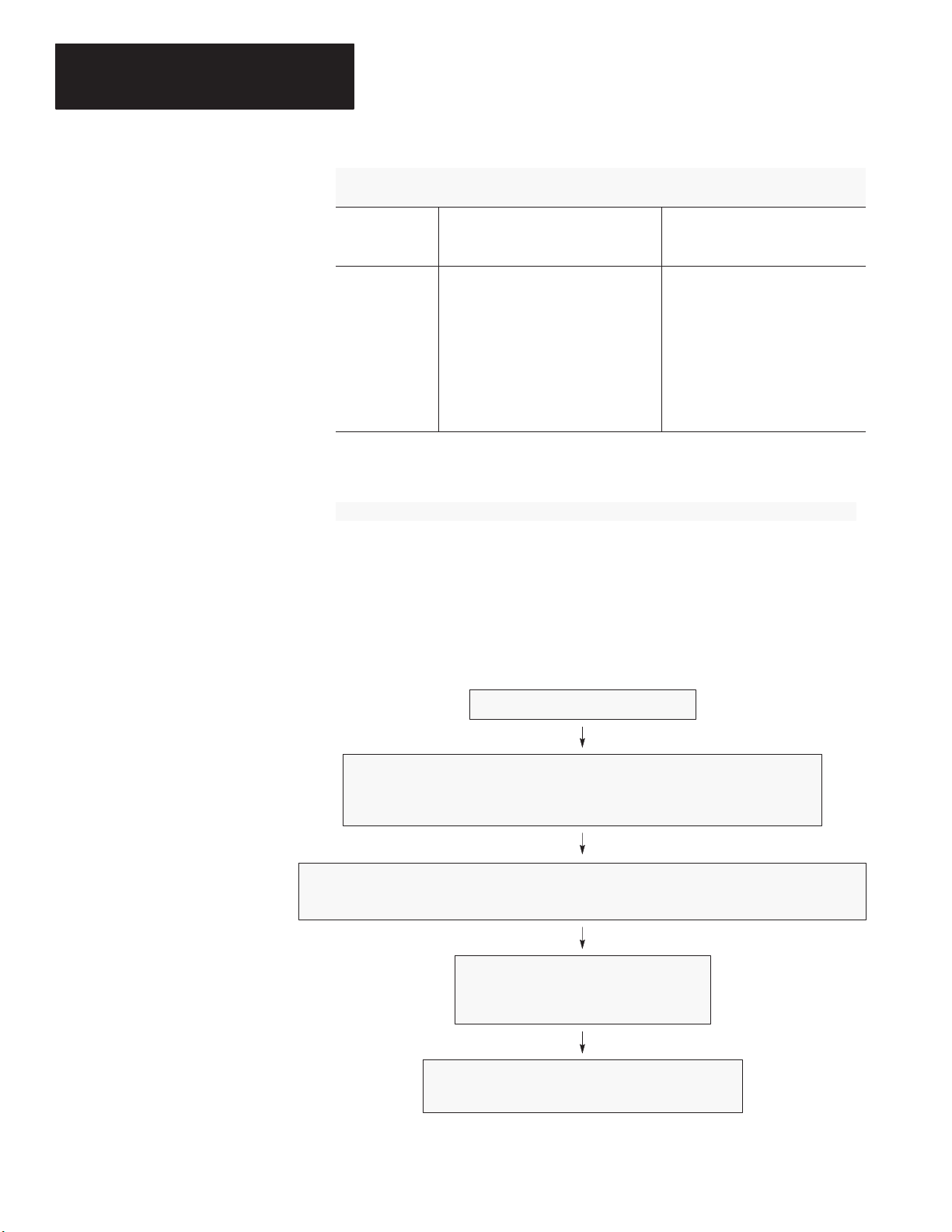
After you finish designing a PLC-5 protected-processor system, your primary
role as system administrator becomes preventing end users from defeating
whatever security mechanisms you designed into the system.
Main Design of System Complete
System Administrator Determines Which Privileged Areas Require Protection
What classes of users need to be accommodated?
Which features do they need to access?
System Administrator Identifies Which Portions of Memory Require Protection
In what areas of which data or program files would alterations interfere with the intended operation?
System Administrator Sets Up and Tests
Passwords and privileges
DTEP mechanism
System Administrator Turns System Over to End User
Keeps privilege to modify privileges
1-2
Page 8

Passwords and Privileges
Chapter 1
Planning for a Protected System
Tip
Maintaining control over the
privilege to modify privileges
is critical to the successful use
of the DTEP mechanism.
The privilege classes in a PLC-5 processor are not necessarily hierarchical.
Class-1 privileges are considered “higher” than the others only because no
one can remove the privilege to modify privileges from class 1. It would be
logical for you, as system administrator, to treat class 1 as the highest class
and then define privileges accordingly, working down to class 4. Typically,
you should grant the privilege to modify privileges only to the highest level
and never reveal that password to other users. Because of this, you must
anticipate end-user needs and set up passwords and privileges accordingly.
As system administrator, you should protect critical program and data
files according to your needs—e.g., by setting these files to “read only”
or “no read, no write” for all classes other than class 1. This protects
against any modification of your logic and also determines which program
files are screened during download mode. You should also configure all
communications channels—including currently unused channels—to
appropriate privilege classes.
Data-Table Element Protection
The PLC-5 protected processor’s unique security features allow you to define
areas of memory that cannot be altered by anyone other than a class-1 user.
During online programming by end users, the PLC-5 protected processor acts
as a filter to screen and prevent requests to:
• add ladder code that could write to or otherwise manipulate protected
data-table addresses
• modify protected
- data-table words through write operations
- I/O image elements through I/O forcing
When: And: This happens:
The end user is
not authorized to
modify privileges
DTEP is enabled
The processor status file contains the
value for a DTEP file (see page 3-2)
A screened command request is received
by the processor (see page 3-5)
DTEP is enabled
The screening option occurs
during online program editing
1-3
Page 9

Chapter 1
Planning for a Protected System
Tip
The status-file location
of the value for the
DTEP file (S:63) is
protected automatically;
therefore, you do not
have to protect it individually.
Examples of memory areas that you should protect using the DTEP
mechanism might include:
• security-critical output words
• certain counter, timer, or BT/MG/PD control structures
• integer storage registers
• data-table words used to specify indirect addresses in critical data tables
• processor status file words that configure the system, such as:
Word(s) Use
S:9
S:26 User control bits
S:29 Fault routine number
S:30-31 Selectable timed interrupt (STI) configuration
S:46-50 Processor input interrupt (PII) configuration
S:54
S:56
S:77 Communication time slice
S:78-123
①
If you are verifying that performance parameters are not violated, for example.
Maximum scan time
STI maximum scan time
PII maximum scan time
Main control program (MCP) configuration and individual MCP
maximum scan times
①
①
①
①
As system administrator, you can give end users some flexibility in
integrating a system but still maintain control over critical STI, PII, or
fault-routine logic. After securing the above registers with DTEP, you
can define a number of unprotected empty ladder files and include jumps
to subroutines (JSRs) specifying these files at the end of critical routines.
The end user can then add logic to an STI, for example, without opening
the actual STI file for modification.
The DTEP mechanism also provides for certain protections against
unauthorized changes made by an end user using offline programming
software:
• During downloading of a protected processor image file, the protected
processor screens all end-user ladder-type program files—including
structured-text and SFC files—for operands violating the DTEP ranges.
• I/O force operations cannot be downloaded; therefore, they must be done
on line.
• Offline changes made to the values stored in protected data-table
locations can be nullified if you, the system administrator, follow good
programming practices and initialize all data-table locations to
their desired values off of the processor’s first scan flag (S:1/15).
1-4
Page 10
Chapter 1
Planning for a Protected System
S:17
11
S:17
ASCII
File
CTU
COUNT UP
Counter
Preset
Accum
U
11
As a means of monitoring end-user attempts to bypass security mechanisms,
you can monitor the status-file minor-fault bit (S:17/11). This bit indicates a
protection-violation attempt. It can be used to count intrusion attempts if you
add a rung of ladder logic that increments a counter and clears the minorfault bit on each attempt.
C5:0
10
CU
DN
0
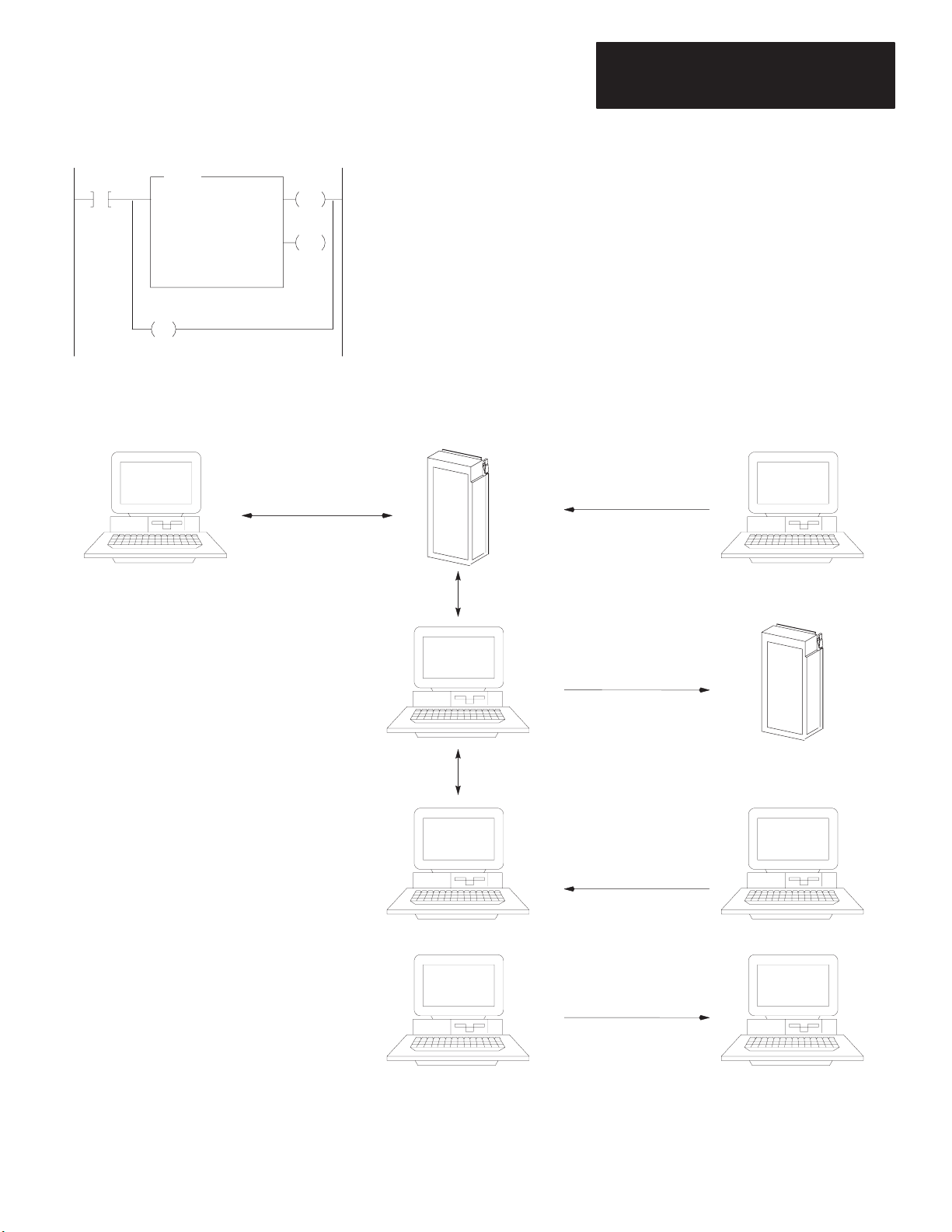
Program-File Conversion Rules
Follow the rules outlined below when sharing program files among
standard enhanced PLC-5 processors and PLC-5 protected processors.
Protected (PLC-5/x6) Processor Standard (PLC-5/x0) Processor
Cannot export/import ASCII files
to/from a protected processor
X
Can save/restore protected-processor
files to protected processor
PLC-5/x
Processor
Can restore standard-processor
files to protected processor
6
PLC-5/x0
Offline File
Can convert protected-processor files
to files for different protected processor
PLC-5/x6
Offline File
PLC-5/x6
Offline File
PLC-5/x6
Offline File
Cannot restore protected-processor
files to standard processor
X
Can convert standard-processor
files to protected-processor files
Cannot convert protected-processor
files to standard-processor files
X
PLC-5/x0
Processor
PLC-5/x0
Offline File
PLC-5/x0
Offline File
1-5
Page 11

Chapter
2
Configuring Passwords and Privileges
Using this Chapter
If you want to read about: Go to page:
Guidelines for assigning passwords and privileges
Assigning passwords and privileges to classes 2-3
Assigning default privilege classes for channels and offline files 2-6
Assigning read and write privileges for channels 2-7
Assigning privileges for specific stations/nodes 2-8
Assigning read and write privileges for a program file 2-9
Assigning read and write privileges for a data-table file 2-10
Restoring default privilege classes 2-11
Acquiring the privileges of a different class 2-11
2-2
Important: When you first install the 6200 Series PLC-5 Programming
Software, this screen appears:
+––––––––––––––––––––––––––––––––––––––––––––––––––––––––––––––––––––––––––––––+
| Contents: PLC–5 Prog Dev & Doc SW |
| Catalog Number: 62xx–PLC5 |
| Part Number: xxxxxx–xx |
| Release Number: x.x Quantity: x Disks |
+––––––––––––––––––––––––––––––––––––Status––––––––––––––––––––––––––––––––––––+
| 0% Complete +-------------------------------------------------+ |
| | | |
| +-------------------------------------------------+ |
| 0k Copied 0% 25% 50% 75% 100% |
+––––+–––– SELECT APPROPRIATE PASSWORD & PRIVILEGE OPTION –––+––––+
| |NO – Do not provide the ability to configure Passwords & Privileges| |
| |YES – Provide the ability to configure Passwords & Privileges | |
| |RETURN TO DOS – Refer to Documentation | |
| +––––––––––––––––––––––––––––––––––––––––––––––––––––––––––––––––––––+ |
| |
| |
You must choose the following option:
YES - Provide the ability to configure Passwords & Privileges
For more information on installing the software as well as configuring
passwords and privileges, see the PLC-5 Programming Software
Configuration and Maintenance manual, publication 6200-6.4.6.
2-1
Page 12

Chapter 2
Configuring Passwords and Privileges
Guidelines for Assigning Passwords and Privileges
The privilege classes are the upper-level organization for the
password structure.
Privilege Hierarchy
User’s Terminal
Privilege Classes
Node Privileges
Channel Privileges
File Privileges
Data Highway Plus
1 or 2 or 3 or 4
2A
1A 1B
0
2B
PLC-5
Processor
Program
Data
As system administrator, you should:
Define the passwords and privileges for each processor in the system
Assign default class privileges to communication channels and offline files
Set read and write access to channel-configuration screens
Assign privileges for any nodes requiring privileges other than channel’s default
Set read and write access to program files
Set read and write access to data files
Tell users what privilege classes they can use and the appropriate passwords
End user must enter new class and password to acquire privileges of a class other than the default
2-2
Page 13

Chapter 2
Configuring Passwords and Privileges
Assigning Passwords and Privileges to Classes
6200
Main Menu
Online
Program
F1
Privileges
Password
or
General
Utility
F7
F5
Modify
Offline
Program
F3
As system administrator, you can assign a unique password to each of four
privilege classes (classes 1-4). For each class, you can then assign access
to certain software operations (such as modifying program files, data-table
files, or channel configurations).
Assigning Passwords to Classes
To assign a password to a class, follow the steps on the left.
Current: Class1 Privilege Class Information Default: Class1
+==============================================================================+
| Privileges \ Privilege Class Names Class1 Class2 Class3 Class4 |
|––––––––––––––––––––––––––––––––––––––––––––––––––––––––––––––––––––––––––––––|
| Modify Privileges | X | X | X | X |
| Data Table File Create/Delete | X | X | X | X |
| Program File Create/Delete | X | X | X | X |
| Logical Write | X | X | X | X |
| Physical Write | X | X | X | X |
| Logical Read | X | X | X | X |
| Physical Read | X | X | X | X |
| Mode Change | X | X | X | X |
| I/O Force | X | X | X | X |
| SFC Force | X | X | X | X |
| Clear Memory | X | X | X | X |
| Restore | X | X | X | X |
| On–line Editing | X | X | X | X |
+==============================================================================+
Press a function key.
>
Rem Prog 5/46 File PROTECT
Modify Toggle
Passwrd Priv
F1 F10
F1
Privilege Class Name
Press the
Enter key if
setting for
the first time
Enter
or
Old Password
Enter
New Password
Enter
New Password
Important: As system administrator, you must remember your password.
There is no way for you or Allen-Bradley to go back online and perform any
system-administration functions, such as resetting passwords and privileges,
without this password. If there is any chance that you might forget it or
become unavailable when it is needed, write the password down and put it in
a secure place.
Enter
Assigning Privileges to a Class
You can define class 1 as having all privileges, equivalent to those of system
administrator. You should then define the remaining three classes as having
fewer privileges, making sure that only you, the system administrator, retain
the Modify Privileges privilege.
2-3
Page 14

Chapter 2
Configuring Passwords and Privileges
For example, you can decide that class 1 is for the system administrator, class
2 for plant engineers, class 3 for maintenance engineers, and class 4 for
operators. You can then set privilege classes as follows:
Privilege Class1 Class2 Class3 Class4
Modify Privileges
Create/Delete Data Files X X
Create/Delete Program Files X X X
Download Blocks of Processor Memory (Logical Write) X X X X
Download All Processor Memory (Physical Write) X X X X
Upload Blocks of Processor Memory
②
(Logical Read)
Upload All Processor Memory (Physical Read) X X X X
Change Processor Mode X X X X
Force I/O X X X
Force Transitions in Sequential Function Charts X X X
Clear Memory X
Restore Memory from Archive X X X
Edit On-line X X
①
X indicates that the privilege is enabled for this class.
②
Without this, a user cannot even see the program directory; required for all but physical reads.
①
X
X X X X
6200
Main Menu
Online
Program
F1
Privileges
Cursor to Intersection
of Privilege and Class
or
General
Utility
F7
F5
Toggle
Privilege
F10
Offline
Program
F3
Enable or disable a privilege for a class by following the steps on the left.
Current: Class1 Privilege Class Information Default: Class1
+==============================================================================+
| Privileges \ Privilege Class Names Class1 Class2 Class3 Class4 |
|––––––––––––––––––––––––––––––––––––––––––––––––––––––––––––––––––––––––––––––|
| Modify Privileges | X | X | X | X |
| Data Table File Create/Delete | X | X | X | X |
| Program File Create/Delete | X | X | X | X |
| Logical Write | X | X | X | X |
| Physical Write | X | X | X | X |
| Logical Read | X | X | X | X |
| Physical Read | X | X | X | X |
| Mode Change | X | X | X | X |
| I/O Force | X | X | X | X |
| SFC Force | X | X | X | X |
| Clear Memory | X | X | X | X |
| Restore | X | X | X | X |
| On–line Editing | X | X | X | X |
+==============================================================================+
Press a function key.
>
Rem Prog 5/46 File PROTECT
Modify Toggle
Passwrd Priv
F1 F10
2-4
Page 15

Chapter 2
Configuring Passwords and Privileges
If you want a class to have the ability to: Enable this privilege/operation:
Enable/Disable privileges for each class
Modify Privileges
Important: If you are using DTEP, disable this privilege for
every class except class 1 (system administrator).
Create or delete data-table files
Create or delete program files
Restore a processor memory file using a logical address
Data Table File Create/Delete
Program File Create/Delete
Logical Write
In general, this should be paired with a Physical Write
Restore a processor memory file with a physical address
Physical Write
In general, this should be paired with a Logical Write
Read from the processor using a logical address
Logical Read
In general, this should be paired with a Physical Read
Important
:
Without this, a user cannot even see the program
directory; required for all but Physical Read.
Read the processor’s memory with a physical address
Physical Read
In general, this should be paired with a Logical Read.
Change processor mode when the keyswitch on the processor
Mode Change
is set to REMOTE
Enable or disable forces in the system; clear all I/O forces
Enable or disable SFC forces; force individual transitions on or
I/O Force
SFC
Force
off; or clear all SFC forces
Clear the processor memory
Restore or merge a processor memory file
Edit a program file in any processor mode
①
Important: You cannot delete this privilege from class 1 (system administrator).
Clear Memory
Restore
Online Editing
①
①
①
2-5
Page 16

Chapter 2
Configuring Passwords and Privileges
Assigning Default Privilege Classes to Communication Channels and Offline Files
6200
Main Menu
Online
Program
F1
Privileges
or
General
Utility
F7
Channel
Overview
F4
Channel
F2
Offline
Program
F3
A default privilege class determines the class of a particular channel
and of all stations/nodes attached through that channel. If you have a
specific node that requires privileges other than those that the channel’s
class assignment allows, you can specify the privilege class for that node
separately (see page 2-8).
Communication channels and offline files start out with class-1 privileges.
Assign a new default privilege class for a communication channel or offline
file by following the steps on the left.
Channel Privileges
Default Privilege Class
Priv. Class Class 1 Class 2 Class 3 Class 4
Channel 0: SYSTEM (P–2–P) CLASS 1 RW RW RW RW
Channel 1A: DH+ CLASS 1 RW RW RW RW
Channel 1B: SCANNER MODE CLASS 1 RW RW RW RW
Channel 2A: UNUSED CLASS 1 RW RW RW RW
Channel 2B: UNUSED CLASS 1 RW RW RW RW
Channel 3A: N/A CLASS 1
Offline: CLASS 3
Press a function key or enter a value.
>
Rem Prog Forces:None 5/46 File PROTECT
Node Select
Priv Priv
F3 F10
Cursor to Intersection
of Channel and Default
Privilege Class
Select (T
oggle)
Privileges
F10
Important: If you are using DTEP, assign defaults to all channels—
including any currently unused channels.
2-6
Page 17

Chapter 2
Configuring Passwords and Privileges
Assigning Read and Write Privileges for Communication Channels
6200
Main Menu
Online
Program
F1
Privileges
Cursor to Intersection
of Channel and
Privilege Class
or
General
Utility
F7
Channel
Overview
F4
Channel
F2
Offline
Program
F3
The read and write privileges that you see on the Channel Privileges screen
apply to a privilege class’ read and write access to the Channel Configuration
screen of each channel.
Important: Removing both read and write access from class 1 for a channel
prevents even you, the system administrator, from configuring that channel.
Make sure that class 1 retains whatever access is necessary to each channel.
As system administrator, you specify read and write privileges for a channel
by following the steps on the left.
Channel Privileges
Default Privilege Class
Priv. Class Class 1 Class 2 Class 3 Class 4
Channel 0: SYSTEM (P–2–P) CLASS 1 RW RW RW RW
Channel 1A: DH+ CLASS 1 RW RW RW RW
Channel 1B: SCANNER MODE CLASS 1 RW RW RW RW
Channel 2A: UNUSED CLASS 1 RW RW RW RW
Channel 2B: UNUSED CLASS 1 RW RW RW RW
Channel 3A: N/A CLASS 1
Offline: CLASS 3
Press a function key or enter a value.
>
Rem Prog Forces:None 5/46 File PROTECT
Node Select
Priv Priv
F3 F10
If you want the class to be able to: Select this option:
Read the configuration information only
Read and change the configuration information
Neither read nor modify channel configuration information (Blank)
R
RW
Select (T
Privileges
F10
oggle)
Set up the read and write privileges for each channel’s diagnostic file
(Channel Status screen) through the Data Table Privileges screen (see
page 2-10).
2-7
Page 18

Chapter 2
Configuring Passwords and Privileges
Assigning Privileges for Specific Stations/Nodes
6200
Main Menu
Online
Program
F1
Overview
Node Privileges
Cursor to Appropriate
Field in Channel Column
Select (T
Offline
Program
or
F3
General
Utility
F7
Channel
F4
F3
oggle) Privileges
Each station/node that attaches to this processor’s DH+ channel defaults to
the privilege class that is assigned to its channel; as system administrator,
however, you can give a particular node a unique privilege class.
Important:
• Node privilege classes override the default privilege class of the channel
that is assigned on the Channel Privilege screen.
• If you give any node class-1 privileges, an end user can configure a
terminal to attach as that node, creating a potential security risk.
Specify a privilege class for a node by following the steps on the left.
Node Privilege Class
Channel Station Address Link ID Privilege Class Name
0 0 0
0 0 0
0 0 0
0 0 0
0 0 0
0 0 0
0 0 0
0 0 0
0 0 0
0 0 0
0 0 0
0 0 0
0 0 0
0 0 0
Press a function key or enter a value.
>
Rem Prog Forces:None 5/46 File PROTECT
Select
Priv
F10
F10
Until Desired Channel is Displayed
Cursor to Appropriate
Field in Station
Enter Station Address
Cursor to Appropriate
Field in Link ID Column
Cursor to Appropriate
Field in Privilege Class Name Column
Select (T
Address Column
(0–77 Octal)
Enter
Link ID
oggle) Privileges
F10
2-8
The field in this column: Specifies the:
Channel
Station
Link
ID
Address
channel to which this node is attached
station address of the node on the channel
link number used to identify the DH+ link to which the
node you are specifying is attached
Privilege
Class Name
privilege class of the node
By default, the privilege class of the node is the privilege
class of the channel
Page 19

Chapter 2
Configuring Passwords and Privileges
Assigning Read and Write Privileges for a Program File
6200
Main Menu
Online
Program
F1
Processor
Functions
Privileges
Cursor to Intersection
of File Description and
Privilege Class
Privileges
or
F1
Modify
F2
Toggle
F10
Offline
Program
F3
As system administrator, you can assign read and write privileges for each
program file in a processor in order to limit the ability of users to view or
change it.
Important:
• You cannot modify read and write privileges to system (file 0) or
undefined files.
• Removing both read and write access from class 1 for a program file
prevents even you, the system administrator, from accessing that file.
Make sure that class 1 retains whatever access is necessary to each file.
• Download screening for DTEP violations is directed at program files for
which classes 2-4 have write privileges. If you generate files offline that
control critical logic, you must remove all privileges to write to these files
from classes 2-4 before DTEP will let you download the files.
To specify read and write privileges for a program file, follow the steps on
the left.
+= PROGRAM FILE PRIVILEGES ======================================[ OFFLINE ]===+
| File Name Type Class1 Class2 Class3 Class4 |
|––––––––––––––––––––––––––––––––––––––––––––––––––––––––––––––––––––––––––––––|
| 0 system RW RW RW RW |
| 1 undefined RW RW RW RW |
| 2 ladder RW RW RW RW |
| |
| |
| |
| |
| |
| |
| |
| |
| |
| |
| |
+==============================================================================+
Press a function key to toggle the privilege.
>
Rem Prog PLC–5/46 Series C Revision G 5/46 File PROTECT
Toggle
Priv
F10
If you want the class to be able to: Select this option:
Read the program file only
Read and change the program file
Neither read nor modify the program file (Blank)
①
You can use this to protect proprietary algorithms from being viewed.
R
RW
①
2-9
Page 20

Chapter 2
Configuring Passwords and Privileges
Assigning Privileges for a Data-Table File
6200
Main Menu
Online
Program
F1
Privileges
Cursor to Intersection
of File Description and
Privilege Class
or
General
Utility
F7
Memory
Map
F1
Modify
F2
Offline
Program
F3
As system administrator, you can assign read and write privileges for each
data-table file in a processor in order to limit the access of users to view or
change data-table file values.
Important:
• You cannot modify read and write privileges to undefined files.
• Removing read and write access for class 1 from a data-table file prevents
even you, the system administrator, from accessing that file. Make sure
that class 1 retains whatever access is necessary to each file.
To specify read and write privileges for a data-table file, follow the steps on
the left.
DATA TABLE PRIVILEGES
FILE TYPE Class 1 Class 2 Class 3 Class 4
0 O output RW RW RW RW
1 I input RW RW RW RW
2 S status RW RW RW RW
3 B binary or bit RW RW RW RW
4 T timer RW RW RW RW
5 C counter RW RW RW RW
6 R control RW RW RW RW
7 N integer RW RW RW RW
8 F floating point RW RW RW RW
9 unused RW RW RW RW
10 unused RW RW RW RW
PROCESSOR MEMORY LAYOUT
821 words of memory used in 64 data table files
23 words of memory used in 3 program files
48678 words of unused memory available
Press a function key to toggle the privilege.
>
Rem Prog PLC–5/46 Series C Revision G 5/46 File PROTECT
Toggle
Priv
F10
If you want the class to be able to: Select this option:
Read the data-table file only
Read and change the data-table file
Neither read nor modify the data-table file (Blank)
R
RW
2-10
Toggle
Privileges
F10
Page 21

Chapter 2
Configuring Passwords and Privileges
Restoring Default Privilege Classes
6200
Main Menu
Online
Program
F1
Password
or
Enter
F10
Return
Default
F7
Offline
Program
F3
As system administrator, you can restore default privileges for a class if the
current edits have not yet been saved.
To restore default privileges, follow the steps on the left.
+= PROGRAM DIRECTORY FOR PROCESSOR: PROTECT======================[ OFFLINE ]===+
| File Name Type Size(words) |
|––––––––––––––––––––––––––––––––––––––––––––––––––––––––––––––––––––––––––––––|
| 0 system 4 |
| 1 undefined 0 |
| 2 ladder 1 |
| |
| |
| |
| |
| += Select New Privilege Class =========+ |
| | | |
| | Privilege Class Name | |
| | Password: | |
| | | |
| += ESC exits ==========================+ |
| |
+==============================================================================+
Enter the class name and password or press a function key.
Rem Prog 5/46 File PROTECT
Return
Default
F7
Changing to a Different Class
6200
Main Menu
Online
Program
F1
Password
Privilege Class Name
Password
or
Enter
F10
Enter
Enter
Offline
Program
F3
If you want to acquire the privileges of a different class (other than the one
that the programming terminal is currently configured for), you must enter
the new class and password.
To acquire the privileges of a different class, follow the steps on the left.
+= PROGRAM DIRECTORY FOR PROCESSOR: PROTECT======================[ OFFLINE ]===+
| File Name Type Size(words) |
|––––––––––––––––––––––––––––––––––––––––––––––––––––––––––––––––––––––––––––––|
| 0 system 4 |
| 1 undefined 0 |
| 2 ladder 1 |
| |
| |
| |
| |
| += Select New Privilege Class =========+ |
| | | |
| | Privilege Class Name | |
| | Password: | |
| | | |
| += ESC exits ==========================+ |
| |
+==============================================================================+
Enter the class name and password or press a function key.
Rem Prog 5/46 File PROTECT
Return
Default
F7
Tip
You can also press ALT-P to select a new privilege class.
2-11
Page 22

Chapter
3
Configuring and Using Data-Table
Element Protection
Using this Chapter
Creating a Protection File
6200
Main Menu
Online
Program
F1
General
Utility
F7
Memory
Map
F1
Create
Data-Table File
F6
If you want to read about: Go to page:
Creating a protection file
Setting up a protection file 3-2
Entering data-table ranges into a protection file 3-3
Screening commands 3-5
Protecting from offline changes 3-5
Understanding restrictions placed on the system 3-6
Testing the protection file 3-8
3-1
As system administrator, implement DTEP by:
• obtaining system-administrator (class-1) privileges
• creating an integer data-table file to serve as the DTEP file
• entering the chosen integer file’s number into the processor’s status file
(data-table file 2)
• entering the data-table ranges that need to be protected into the DTEP file
As system administrator, follow the steps on the left to create an integer
data-table file to be used as the DTEP file.
Make sure that this file is just large enough to contain the number of
elements that is three times the number of ranges you are protecting. See
page 3-3 for guidelines on determining the size of your protection file.
DATA TABLE MAP
FILE TYPE LAST ADDRESS SIZE (elements) SIZE (words)
0 O output O:177 128 134
1 I input I:177 128 134
2 S status S:127 128 134
3 B binary or bit B3/15 1 7
4 T timer T4:0 1 9
5 C counter C5:0 1 9
6 R control R6:0 1 9
7 N integer N7:30 31 37
8 F floating point F8:0 1 8
9 F floating point F9:0 1 8
10 unused 0 6
PROCESSOR MEMORY LAYOUT
853 words of memory used in 64 data table files
108 words of memory used in 16 program files
48191 words of unused memory available
Enter address to create
> N10:10
Rem Prog PLC–5/46 Series C Revision G 5/46 File PROTECT
Enter Last Address
3-1
Page 23

Chapter 3
Configuring DTE Protection
Initiating the Protection Mechanism
6200
Main Menu
Online
Program
F1
Cursor to Progam File
Monitor File
F8
Edit
F10
Insert
Rung
F4
Insert
Instruction
F4
Entering the file number of the DTEP file into element 63 of the status file
(S:63) automatically initiates the DTEP mechanism for end users.
As system administrator, use the steps at the left and enter a ladder
instruction moving the desired DTEP file number into S:63 of the status file.
This ladder instruction can be temporary as long as it executes once to set the
value in the status file. After that, you can remove the ladder instruction and
the program can be archived (saved) with protection in place.
Important: The validity of the file number moved into address S:63 is not
checked until a screened command is received from an end user during
online programming. If it is not valid:
• an error code is returned
• a minor fault (S:17/12) is set
You, as system administrator, must follow the steps on page 3-8 to force
validation of this file number before turning the system over to end users.
The protection mechanism remains in effect for the end user until you either:
• give the Modify Privileges privilege to the end user
• clear the DTEP file entry from the status file
When DTEP is in effect, the following are automatically protected from
modification by commands issued by an end user:
• element 63 of the status file
• the entire DTEP file
Important: For the system administrator, possession of the privilege to
modify privileges overrides the protection mechanism.
3-2
Rung conditioned
off first scan bit.
S:1
10
Moves a value of 10 into S:63,
which configures the protection
file to be file number 10.
MOV
Move
Source
Dest
10
S:63
Page 24

Chapter 3
Configuring DTE Protection
Entering Data-Table Ranges into the Protection File
6200
Main Menu
Online
Program
F1
Cursor to Progam File
Monitor File
F8
Data
Monitor
F8
Enter Protection File Address
As system administrator, you specify ranges of protection in the DTEP file
using three consecutive words for each range entry.
Enter the file ranges that you want protected by following the steps on
the left.
Address 0 1 2 3 4 5 6 7 8 9
N10:0 0 0 0 0 0 0 0 0 0 0
N10:10 0 0 0 0 0 0 0 0
Press a function key or enter a value.
N10:0 =
Rem Prog Forces:None Data:Decimal Addr:Decimal 5/46 File PROTECT
Change Specify Next Prev
Radix Address File File
F1 F5 F7 F8
Follow these guidelines:
• Enter the protection-range three-word entries starting at element zero (0)
and proceeding in contiguous entries for all of the ranges to be specified.
Enter the ranges in the
following format:
Data-Table
File Number
FFF
Tip
Starting
Element
Number
(Ø-999)
Ending
Element
Number
(Ø-999)
SSS EEE
Excess space in the
DTEP file is filled with
zeros by default; any
resultant “0 0 0” grouping
would be interpreted as
protecting file 0, element 0—
i.e., O:Ø. Avoid this by
placing a ‘–1’ in any intentionally unused space.
• The starting and ending elements within each range entry must be in
ascending order—except when protecting only one element and they
are therefore equal.
• Specify a starting element of zero (0) and an ending element of 999 to
protect an entire file regardless of how many elements are actually in
the file.
• Indicate intentionally unused protection range entries in the DTEP file by
placing a ‘
-1’ in the Data-Table File Number field.
• Enter any number of protection ranges up to 333.
• Make the DTEP file only as large as is necessary to specify all of the
required protection ranges.
While using the protection mechanism does not affect the performance of
Run mode program execution in any noticeable way, it can affect the
responsiveness of the processor to commands that are received from the
end user. Follow these guidelines to minimize this:
- Minimize the number of the protection ranges specified.
Rather than specifying several protection ranges in a data-table file,
consider protecting the entire file with a single range.
- Keep the size of the DTEP file at the minimum required for the
number of protection ranges required.
3-3
Page 25

Chapter 3
Configuring DTE Protection
Tip
Even if you, as system
administrator, have
already removed the
privilege to write to a
data-table file, you can
still protect it with DTEP
and benefit from DTEP’s
more extensive protection
features (e.g., against
unauthorized writes by enduser output instructions).
This is important because the protected processor scans the file
completely, from the first to the last element, when verifying the
file as well as when screening the DTEP-screened commands.
Figure 3.1
Entering Ranges in a DTEP File
Address 0 1 2 3 4 5 6 7 8 9
N10:0 0 0 3 1 1 2 7 0 100 11
N10:10 10 10 –1 0 0 16 0 999
Processor Status File
DTE
Protection File #
S:63
Press a function key or enter a value.
N10:0 =
Rem Prog Forces:None Data:Decimal Addr:Decimal 5/46 File protected
Change Specify Next Prev
Radix Address File File
F1 F5 F7 F8
10
• File 0 (output image) is protected from element 0 to 3
• File 1 (input image) is protected from element 1 to 2
• File 7 is protected from element 0 to 100
• File 11 element 10 only is protected
• The next range is skipped
• All of file 16 is protected
DTEP File #10
Starting
Data-Table
File
Number
Element
Number
00 3
11 2
7 0 100
11 10 10
-1 0 0
16 0 999
Ending
Element
Number
These ranges are entered in decimal by default. If you are entering a range
from one of the I/O image files, you can press
F2 — Octal Data and enter the range in octal. When you change back to
F1 — Change Radix then
decimal, the conversion is done for you.
Address 0 1 2 3 4 5 6 7 8 9
N10:0 000000 000000 000003 000001 000001 000002 000007 000000 000144 000012
N10:10 000012 000012 177777 000000 000000 000020 000000 001747
Important: The validity of your protection-range entries is not checked
when you enter them via data monitor, but they are validated when a
screened command is received from an end user during online programming.
If they are not valid:
• an error code is returned
• a minor fault (S:17/12) is set
You, as system administrator, must follow the steps on page 3-8 to force
validation of these entries before turning the system over to end users.
3-4
Page 26

Chapter 3
Configuring DTE Protection
Screening Commands
Protecting from Offline Changes
During online program editing by the end user, the protected processor
screens all communications commands that can be used to modify data-table
elements, manipulate addresses, or force I/O. If the DTEP mechanism is
enabled—i.e., the user cannot modify privileges and there is a valid DTEP
file indicated in S:63—the protected processor screens each command for
access to protected data-table areas. This process checks all ranges in the
DTEP file. If a violation is found, the request is rejected, an error
code—
and minor-fault bit S:17/11 is set.
Command screening occurs during online programming by an end user—
i.e., when the programming software is connected directly to the processor.
When an end user changes a processor image off line—i.e., when the
programming software is connected to a file image of the processor—
most commands cannot be directly screened by the processor for
protection violations. For offline changes, therefore, other methods
help prevent protection violations.
Data Table Element Protection Violation—is returned,
Data-Table Files
As system administrator, you should follow good programming practices and
initialize all data-table locations to their desired values off the processor’s
first scan flag (S:1/15). Because the DTEP file specifies only the ranges and
not the values that should be in each location, the protected processor cannot
prevent or detect any changes that are made to the values stored in the
data-table files during offline programming. When you initialize all
data-table locations to their desired values off the processor’s first scan flag,
any problems that might have occurred due to protection violations made
during offline writing to data-table locations are nullified.
I/O Force Tables
To protect the processor operation from possible I/O force operations
included in the processor image through offline programming, the protected
processors do not accept any I/O force table changes while in download
mode. The data in the I/O force tables remain unchanged. At the end
of any download to a protected processor, the I/O force tables are clear
of any forces and a warning appears on your terminal that indicates that any
forces in the archive file were not downloaded.
Insert Elements
The protected processor does screen ladder and structured-text insert-element
instructions during downloading in order to ensure that the addresses
protected by the DTEP mechanism are not reprogrammed.
3-5
Page 27

Chapter 3
Configuring DTE Protection
As system administrator, you should have set up the basic protection for the
processor application using the passwords and privileges capabilities
discussed in Chapter 2. While doing this, you should have removed write
privileges from all classes (except class 1) for all program and data files
that you consider to be critical for the security of the application program.
Program files that end users create afterwards are not protected in this
way, and they default to allow all four classes to have both read and write
privileges. This distinction allows the processor to key its download
screening to any download request made that has a ladder or structured-text
program file as its destination and also has write privileges allowed for
class 2.
Any protection violation causes the download to abort, the download screen
displays the message
Data Table Element Protection Violation, and
the screen continues displaying the program file number that caused the
protection violation. Use this information to trace the instruction/operand
combination that caused the protection violation.
Understanding Restrictions Placed on the System
On detecting a protection-violation error during download mode, the
processor responds as if a download timeout had occurred, sets the processor
mode back to program (or remote program), and sets major fault “Bad User
Program Memory” with a fault code of “Download Aborted” (19).
To reduce security risks, the following restrictions have been placed on the
use of a protected system.
Indirect Addressing
Because indirect addressing lets the end user determine the effective datatable address at run time by manipulating the indirect location in ladder
program, a security risk could exist. When DTEP is enabled and the end user
does not have the ability to modify privileges, the protected processor
screens for indirect addressing in ladder and structured-text instructions that
are inserted. The security system:
• rejects all indirect addressing at the file level—e.g., N[N7:0]:20
• allows indirect addresses at the element level—e.g., N12:[N7:0]—only if
the file specified contains no protected elements
3-6
• rejects indirect addressing at the element level if the file specified
contains any protected elements
If a protection violation occurs, the request is rejected, an error code
Table Element Protection Violation) is returned, and minor-fault bit
(Data
S:17/11 is set.
Page 28

Chapter 3
Configuring DTE Protection
Indexed Addressing
Because indexed addressing lets the end user determine the effective datatable address at run time by manipulating the status-file index word (S:24)
location in ladder program, another risk could exist. When DTEP is enabled
and the end user does not have the ability to modify privileges, the protected
processor screens for indexed addressing and prevents insertion if the file
number addressed intersects with any of the protected ranges in the DTEP
file. If a protection violation occurs, the request is rejected, an error code
(
Data Table Element Protection Violation) is returned, and
minor-fault bit S:17/11 is set.
Since the processor does not prevent the overrunning of data-table file
boundaries through the use of indexed addressing, a small security risk does
still exist with this screening. While this screening mechanism checks to
make sure that no protected elements exist in the addressed file, the
mechanism cannot check for the possibility of overwriting a protected
element in subsequent files since it has no way of knowing:
• how many data-table files the indexed instruction might possibly affect
during execution
• what the value of the .POS field of the control structure will be at
execution time
Important: Make sure that your index-addressed instructions do not exceed
the file boundary.
Writing Data to Memory through the Coprocessor Port
The products using the coprocessor port use two raw data-transfer
mechanisms that do not fall under the current passwords and privileges
functionality. Therefore, any coprocessor is prevented from writing raw
data to processor memory when the DTEP mechanism is enabled. The
override privilege, Modify Privileges, has no effect in this case because
there are no privileges associated with the coprocessor port’s raw
data-transfer mechanisms.
On detecting a raw-data transfer request that causes a protection violation,
the processor responds by setting a fault flag back to the coprocessor and
setting major fault “Channel 3 Device Fault” (bit 6) in the processor with a
fault code of
Protection Invoked (106).
COPRO Transfer Not Valid with Data Table Element
Screened commands coming through the coprocessor port are screened
according to the rules of the standard DTEP mechanism.
Importing and Exporting ASCII Files
Because of the data-protection issues that the protected processor is designed
to address, you cannot use the 6200 Series programming software’s ASCII
processor memory import or export functions on a protected processor
memory file.
3-7
Page 29

Chapter 3
Configuring DTE Protection
Testing the Protection File
When processing each protection-screened command while protection is
enabled, the validation process checks to make sure that the:
• DTEP file
- exists
- is an integer file
• data-table file number is valid
• range of values in the DTEP file are valid
• file numbers exist
• starting/ending element value pairs are equal or in increasing order
• ranges represent words actually located in the indicated data-table file
If any of these is not the case,
• an error code (DTE Protection File Invalid) is returned
• a minor fault (S:17/12) is set
The value ‘-1’ is accepted to nullify an unused entry and is not detected as
an error. The ending element field can be set to ‘999’ regardless of the
number of elements actually in a file, and this is not detected as an error
when validating the protection file.
Important: Any invalid conditions prevent all attempts by an end user to
perform any DTEP-screened commands until the problem is corrected.
As system administrator, thoroughly test the DTEP file before implementing
it for the end user by following these steps:
1. Change your privilege class to one of the previously defined end-
user classes.
2. Attempt a write operation (data-table monitor) to a protected data-
table address.
This forces the validation of the DTEP file. If the file is not valid,
minor-fault bit S:17/12 is set and further write operations are prevented
until the file error is fixed. If DTEP is operating properly, an error code
(
Data Table Element Protection Violation) is returned, and
minor-fault bit S:17/11 is set.
3. Attempt a write operation to a non-protected data-table address.
This operation should be successful.
4. Change your privilege class back to class 1, and fix any errors.
If you must go back and add further data-table elements to existing DTEPs
following integration of a system, first check to see that end users have not
already accessed any of the to-be-protected elements in their instruction
addressing. If you add protection to elements that have already been used,
you are, in effect, locking end users out of their own logic.
3-8
Page 30

Index
PLC-5 Protected Processor
Supplement
A
areas to protect, 1-4
attempts to bypass security mechanisms,
monitoring, 1-5
audience for this supplement, i
C
classes
assigning privileges to, 2-2
changing, 2-11
definition, i
commands
screened, i, 1-3
screened by protection mechanism,
3-5
communication channel
assigning default privilege class to,
2-6
limiting access to, 1-1
protecting, 1-3
control structures, protecting, 1-4
coprocessor port, 3-7
critical data tables, protecting, 1-4
D
data files
limiting access to, 1-1
protecting, 1-3
data-table element protection. See
DTEP
data-table write, preventing, 1-2
default privilege classes
assigning to all channels, 2-6
restoring, 2-11
download, aborted due to DTEP
violation, 3-6
downloading, protection during, 1-4
downloading files containing critical
logic, requirements before, 2-9
DTEP
definition, i
implementing, 3-1
testing, 1-2
using, 1-3
DTEP file
automatic protection, 3-2
clearing number from status file, 3-2
creating, 3-1
determining number of protection
ranges, 3-3
determining size, 3-1, 3-3
entering data-table ranges, 3-1
entering data-table ranges in,
guidelines, 3-3
entering data-table ranges in octal,
procedure, 3-4
entering number in status file, 3-1,
3-2
validation, 3-2
entering ranges to protect, 3-3
example, 3-4
example, 3-4
going into, 3-3
maximum number of protection
ranges, 3-3
setting up, 3-2
testing, 3-8
unused protection ranges, indicating,
3-3
verification, 3-4
DTEP mechanism
and offline programming, 3-5
downloaded files, 3-5
initiating, 3-2
offline protection, 1-4
restrictions
coprocessor port, 3-7
indexed addressing, 3-7
screened commands, 3-5
screening operation, 3-5
testing, 3-8
E
end user
enhanced processors, protection
, definition, i
method, 1-1
I–1
Page 31

Index
PLC-5 Protected Processor
Supplement
F
files, downloaded, 3-5
flexibility, maintaining for end users,
1-4
I
I/O force operations, protection from
during download, 3-5
I/O forcing
preventing, 1-1, 1-2, 1-3
protection from during downloading,
1-4
indexed addressing, 3-7
indirect addressing, 3-6
instructions screened during
downloading, 3-5
integer storage registers, protecting, 1-4
J
jumps to subroutines (JSRs), using to
maintain flexibility for end users,
1-4
M
modification of your logic, protecting
against, 1-3
N
nodes attached to DH+ link, limiting
access to, 1-1
O
offline changes, protecting against, 1-4
offline file, assigning default privilege
class to, 2-6
P
password
assigning to a class, 2-3
class 1, importance of remembering,
2-3
system administrator
remembering, 2-3
passwords and privileges
classes, setting up, 1-3
’s, importance of
setting up, 1-3
using, 1-3
privilege classes
assigning to channels, 2-6
assigning to nodes, 2-8
assigning to of
changing, 2-11
defining, 2-2
guidelines for assigning, 2-2
restoring default, 2-11
privileges
assigning to classes, 2-3
assigning to node, 2-8
assigning to programming terminal,
2-8
assigning to station, 2-8
class 1, defining, 2-3, 2-4
class 2, defining, 2-3, 2-4
class 3, defining, 2-3, 2-4
class 4, defining, 2-3, 2-4
Clear Memory, 2-4, 2-5
Create/Delete Data File, 2-5
Create/Delete Data Files, 2-4
Create/Delete Program File, 2-5
Create/Delete Program Files, 2-4
definition, i
disabling for classes, 2-4
Edit On-line, 2-4, 2-5
enabling for classes, 2-4
I/O Force, 2-4, 2-5
Logical Read, 2-4, 2-5
Logical Write, 2-4, 2-5
Mode Change, 2-4, 2-5
Modify Privileges, 2-4, 2-5, 3-2
Physical Read, 2-4, 2-5
Physical W
Restore Memory
SFC Force, 2-4, 2-5
program files
limiting access to, 1-1
protecting, 1-3
protection of, 1-3
fline files, 2-6
rite, 2-4, 2-5
, 2-4, 2-5
I–2
Page 32

Index
PLC-5 Protected Processor
Supplement
programming software,
passwords-and-privileges function,
1-1
choosing, 2-1
protected processor
advantages, 1-2
benefits, 1-1, 1-3
features, 1-1
requirements
hardware, 1-2
software, 1-2
restrictions placed on the system, 3-6
protected system
implementing, 1-2
limits, 3-6
planning for, 1-1
requirements, 1-2
testing, 1-2, 3-2, 3-8
protection file, creating, 3-1
protection violation, setting minor-fault
bit, 3-5
protection-range entries
example, 3-4
validation, 3-4
protection-violation attempts,
monitoring, 1-5
protection-file number, validation, 3-2
importing and exporting ASCII files,
3-7
indexed addressing, 3-7
indirect addressing, 3-6
writing raw data through coprocessor
port, 3-7
rules, conversion of files, 1-5
S
security-critical output words,
protecting, 1-4
SFCs, 1-4
sharing files among processors, rules
for, 1-5
special terms, defined, i
status file, automatic protection, 3-2
status-file minor-fault bit S:17:11,
monitoring through ladder logic,
1-4
status-file words, protecting, 1-4
structured text, 1-4
system administrator
assigning passwords and privileges,
primary tasks, 2-2
definition, i
primary role, 1-2
privileges overriding protection
mechanism, 3-2
R
read and write access, limiting, 1-1
read and write privileges
assigning for a data file, 2-10
assigning for a program file, 2-9
assigning to a communication
channel, 2-7
removing from a communication
channel, 2-7
removing from class 1, warning
against, 2-7, 2-9, 2-10
related information
publications, ii
terminology, i
restrictions placed on the system by
DTEP
T
testing
by system administrator, 1-2
guidelines for, 3-8
U
unauthorized writes, preventing, 1-1
undefined files, inability to modify read
and write privileges, 2-9
unused channels, assigning default
privilege classes to, 2-6
unused ports, protecting, 1-3
using ladder logic, to enter DTEP file
number in status file, 3-2
I–3
Page 33

Allen-Bradley has been helping its customers improve productivity and quality for 90 years.
A-B designs, manufactures and supports a broad range of control and automation products
worldwide. They include logic processors, power and motion control devices, man-machine
interfaces and sensors. Allen-Bradley is a subsidiary of Rockwell International, one of the
world’s leading technology companies.
With major offices worldwide.
Algeria •
Argentina • Australia • Austria • Bahrain • Belgium • Brazil • Bulgaria • Canada • Chile • China, PRC • Colombia • Costa Rica • Croatia • Cyprus • Czech Republic
Denmark •
Jamaica • Japan • Jordan • Korea • Kuwait • Lebanon • Malaysia • Mexico • New Zealand • Norway • Oman • Pakistan • Peru • Philippines • Poland • Portugal • Puerto Rico
Qatar •
United
W
Ecuador • Egypt • El Salvador • Finland • France • Germany • Greece • Guatemala • Honduras • Hong Kong • Hungary • Iceland • India • Indonesia • Israel • Italy
Romania • Russia–CIS • Saudi Arabia • Singapore • Slovakia • Slovenia • South Africa, Republic • Spain • Switzerland • T
Arab Emirates • United Kingdom • United States • Uruguay • V
orld Headquarters, Allen-Bradley
, 1201 South Second Street, Milwaukee, WI 53204 USA, T
enezuela • Y
ugoslavia
el: (1) 414 382-2000 Fax: (1) 414 382-4444
aiwan • Thailand • The Netherlands • T
urkey
Publication
Supersedes
1785-6.5.13 – January 1995
1785-6.5.13 – January 1999
Copyright 1999 Rockwell International Corporation Printed in USA
PN 955133-95
 Loading...