

Page 1

User Manual
Stratix 5700 Ethernet Managed Switches
Page 2
Important User Information
Read this document and the documents listed in the additional resources section about installation, configuration, and
operation of this equipment before you install, configure, operate, or maintain this product. Users are required to
familiarize themselves with installation and wiring instructions in addition to requirements of all applicable codes, laws,
and standards.
Activities including installation, adjustments, putting into service, use, assembly, disassembly, and maintenance are required
to be carried out by suitably trained personnel in accordance with applicable code of practice.
If this equipment is used in a manner not specified by the manufacturer, the protection provided by the equipment may be
impaired.
In no event will Rockwell Automation, Inc. be responsible or liable for indirect or consequential damages resulting from the
use or application of this equipment.
The examples and diagrams in this manual are included solely for illustrative purposes. Because of the many variables and
requirements associated with any particular installation, Rockwell Automation, Inc. cannot assume responsibility or
liability for actual use based on the examples and diagrams.
No patent liability is assumed by Rockwell Automation, Inc. with respect to use of information, circuits, equipment, or
software described in this manual.
Reproduction of the contents of this manual, in whole or in part, without written permission of Rockwell Automation,
Inc., is prohibited.
Throughout this manual, when necessary, we use notes to make you aware of safety considerations.
WARNING: Identifies information about practices or circumstances that can cause an explosion in a hazardous environment,
which may lead to personal injury or death, property damage, or economic loss.
ATTENTION: Identifies information about practices or circumstances that can lead to personal injury or death, property
damage, or economic loss. Attentions help you identify a hazard, avoid a hazard, and recognize the consequence.
IMPORTANT
Identifies information that is critical for successful application and understanding of the product.
Labels may also be on or inside the equipment to provide specific precautions.
SHOCK HAZARD: Labels may be on or inside the equipment, for example, a drive or motor, to alert people that dangerous
voltage may be present.
BURN HAZARD: Labels may be on or inside the equipment, for example, a drive or motor, to alert people that surfaces may
reach dangerous temperatures.
ARC FLASH HAZARD: Labels may be on or inside the equipment, for example, a motor control center, to alert people to
potential Arc Flash. Arc Flash will cause severe injury or death. Wear proper Personal Protective Equipment (PPE). Follow ALL
Regulatory requirements for safe work practices and for Personal Protective Equipment (PPE).
Allen-Bradley, ArmorStratix 5700, Logix5000, Rockwell Automation, Rockwell Software, RSLinx, RSLogix , RSNetWorx, Stratix 2000, Stratix 5700, Stratix 8000, Stratix 8300, Studio 5000, Studio 5000 Automation
Engineering & Design Environment, and Studio 5000 Logix Designer are trademarks of Rockwell Automation, Inc.
Trademarks not belonging to Rockwell Automation are property of their respective companies.
Page 3

Summary of Changes
This manual contains new and updated information. Changes throughout this
revision are marked by change bars, as shown to the right of this paragraph.
New and Updated Information
This table contains the changes made to this revision.
Topic Page
New switch catalog number descriptions 16
New switch dimensions 18, 21
100BASE-FX/SX and 1000BASE-FX/SX port descriptions 23
ArmorStratix 5700 switch installation 57…66
Express Setup on SFP-port switches 67, 68, 70, 73
Power over Ethernet (PoE) configuration in Studio 5000 environment 201
Module-defined data types for 8-, 16-, and 24-port switches 247, 248, 252, 254, 267, 270
CIP data assignments for 8-, 16-, and 24-port switches 271
ArmorStratix 5700 console port 278
Rockwell Automation Publication 1783-UM004E-EN-P - June 2014 3
Page 4

Summary of Changes
Notes:
4 Rockwell Automation Publication 1783-UM004E-EN-P - June 2014
Page 5

Table of Contents
Preface
About the Switches
Studio 5000 Environment . . . . . . . . . . . . . . . . . . . . . . . . . . . . . . . . . . . . . . . . 11
Access Product Release Notes . . . . . . . . . . . . . . . . . . . . . . . . . . . . . . . . . . . . . 12
Additional Resources . . . . . . . . . . . . . . . . . . . . . . . . . . . . . . . . . . . . . . . . . . . . . 13
Chapter 1
Switch Catalog Numbers . . . . . . . . . . . . . . . . . . . . . . . . . . . . . . . . . . . . . . . . . 16
Switch Software Features . . . . . . . . . . . . . . . . . . . . . . . . . . . . . . . . . . . . . . . . . 17
Stratix 5700 Switch Dimensions. . . . . . . . . . . . . . . . . . . . . . . . . . . . . . . . . . . 18
ArmorStratix 5700 Switch Dimensions . . . . . . . . . . . . . . . . . . . . . . . . . . . . 21
Switch Front Panel . . . . . . . . . . . . . . . . . . . . . . . . . . . . . . . . . . . . . . . . . . . . . . . 22
Switch Hardware Features . . . . . . . . . . . . . . . . . . . . . . . . . . . . . . . . . . . . . . . . 22
Configuration Files. . . . . . . . . . . . . . . . . . . . . . . . . . . . . . . . . . . . . . . . . . . . . . . 23
SD Card. . . . . . . . . . . . . . . . . . . . . . . . . . . . . . . . . . . . . . . . . . . . . . . . . . . . . . . . . 23
SD Card Sync . . . . . . . . . . . . . . . . . . . . . . . . . . . . . . . . . . . . . . . . . . . . . . . . 24
Switch Memory Allocation . . . . . . . . . . . . . . . . . . . . . . . . . . . . . . . . . . . . . . . 25
Device Manager Web Interface. . . . . . . . . . . . . . . . . . . . . . . . . . . . . . . . . . . . 26
Hardware Requirements . . . . . . . . . . . . . . . . . . . . . . . . . . . . . . . . . . . . . . 26
Software Requirements . . . . . . . . . . . . . . . . . . . . . . . . . . . . . . . . . . . . . . . 26
Studio 5000 Environment . . . . . . . . . . . . . . . . . . . . . . . . . . . . . . . . . . . . . . . . 27
Hardware Requirements . . . . . . . . . . . . . . . . . . . . . . . . . . . . . . . . . . . . . . 27
Cisco Network Assistant. . . . . . . . . . . . . . . . . . . . . . . . . . . . . . . . . . . . . . . . . . 27
Command Line Interface . . . . . . . . . . . . . . . . . . . . . . . . . . . . . . . . . . . . . . . . . 28
Switch Installation
Chapter 2
Stratix 5700 Switch Installation . . . . . . . . . . . . . . . . . . . . . . . . . . . . . . . . . . . 30
Installation Guidelines. . . . . . . . . . . . . . . . . . . . . . . . . . . . . . . . . . . . . . . . 31
Install or Remove the SD Card (optional) . . . . . . . . . . . . . . . . . . . . . . 33
Verify Switch Operation . . . . . . . . . . . . . . . . . . . . . . . . . . . . . . . . . . . . . . 34
Mount the Switch on a DIN Rail . . . . . . . . . . . . . . . . . . . . . . . . . . . . . . 36
Remove the Switch from the DIN Rail . . . . . . . . . . . . . . . . . . . . . . . . . 38
Ground the Switch . . . . . . . . . . . . . . . . . . . . . . . . . . . . . . . . . . . . . . . . . . . 38
Wire the Switch DC Power Source . . . . . . . . . . . . . . . . . . . . . . . . . . . . 40
Attach the Switch Power Connectors . . . . . . . . . . . . . . . . . . . . . . . . . . 43
Wire the Power over Ethernet DC Power Source. . . . . . . . . . . . . . . . 44
Attach the PoE Power Connector. . . . . . . . . . . . . . . . . . . . . . . . . . . . . . 46
Install an SFP Module (optional) . . . . . . . . . . . . . . . . . . . . . . . . . . . . . . 46
Remove SFP Modules from SFP Module Slots . . . . . . . . . . . . . . . . . . 48
Wire the External Alarms . . . . . . . . . . . . . . . . . . . . . . . . . . . . . . . . . . . . . 49
Attach the Alarm Relay Connector to the Switch . . . . . . . . . . . . . . . 52
Connect to 10/100 and 10/100/1000 Ports . . . . . . . . . . . . . . . . . . . . 52
Connect to 10BASE-T, 100BASE-TX, or 1000BASE-T Ports . . . 53
Connect to PoE Ports. . . . . . . . . . . . . . . . . . . . . . . . . . . . . . . . . . . . . . . . . 54
Connect to SFP Modules . . . . . . . . . . . . . . . . . . . . . . . . . . . . . . . . . . . . . 55
Connect to a Dual-purpose Port . . . . . . . . . . . . . . . . . . . . . . . . . . . . . . . 56
Rockwell Automation Publication 1783-UM004E-EN-P - June 2014 5
Page 6

Table of Contents
Switch Software Features
ArmorStratix 5700 Switch Installation . . . . . . . . . . . . . . . . . . . . . . . . . . . . . 57
Installation Guidelines . . . . . . . . . . . . . . . . . . . . . . . . . . . . . . . . . . . . . . . . 57
Install or Remove the SD Card (optional) . . . . . . . . . . . . . . . . . . . . . . 59
Verify Switch Operation . . . . . . . . . . . . . . . . . . . . . . . . . . . . . . . . . . . . . . 60
Mount the Switch . . . . . . . . . . . . . . . . . . . . . . . . . . . . . . . . . . . . . . . . . . . . 61
Ground the Switch . . . . . . . . . . . . . . . . . . . . . . . . . . . . . . . . . . . . . . . . . . . 62
Connect the Switch to a DC Power Source . . . . . . . . . . . . . . . . . . . . . 64
Wire External Alarms . . . . . . . . . . . . . . . . . . . . . . . . . . . . . . . . . . . . . . . . . 65
Connect to 10/100 and 10/100/1000 Ports . . . . . . . . . . . . . . . . . . . . 66
Connect to PoE Ports . . . . . . . . . . . . . . . . . . . . . . . . . . . . . . . . . . . . . . . . . 66
Set Up the Switch Initially with Express Setup . . . . . . . . . . . . . . . . . . . . . . 67
Chapter 3
Port Numbering. . . . . . . . . . . . . . . . . . . . . . . . . . . . . . . . . . . . . . . . . . . . . . . . . . 76
Global Macro . . . . . . . . . . . . . . . . . . . . . . . . . . . . . . . . . . . . . . . . . . . . . . . . . . . . 82
Smartports. . . . . . . . . . . . . . . . . . . . . . . . . . . . . . . . . . . . . . . . . . . . . . . . . . . . . . . 83
Optimize Ports through Smartports Port Roles. . . . . . . . . . . . . . . . . . 83
Custom Smartport Roles . . . . . . . . . . . . . . . . . . . . . . . . . . . . . . . . . . . . . . 83
Avoid Smartport Mismatches. . . . . . . . . . . . . . . . . . . . . . . . . . . . . . . . . . 84
Power over Ethernet (PoE). . . . . . . . . . . . . . . . . . . . . . . . . . . . . . . . . . . . . . . . 85
Powered Device Detection and Initial Power Allocation . . . . . . . . . 86
Power Management Modes. . . . . . . . . . . . . . . . . . . . . . . . . . . . . . . . . . . . 87
VLANs . . . . . . . . . . . . . . . . . . . . . . . . . . . . . . . . . . . . . . . . . . . . . . . . . . . . . . . . . . 90
Isolate Traffic and Users. . . . . . . . . . . . . . . . . . . . . . . . . . . . . . . . . . . . . . . 91
Isolate Different Traffic Types . . . . . . . . . . . . . . . . . . . . . . . . . . . . . . . . . 92
Group Users . . . . . . . . . . . . . . . . . . . . . . . . . . . . . . . . . . . . . . . . . . . . . . . . . 92
IGMP Snooping with Querier . . . . . . . . . . . . . . . . . . . . . . . . . . . . . . . . . . . . . 93
Spanning Tree Protocol. . . . . . . . . . . . . . . . . . . . . . . . . . . . . . . . . . . . . . . . . . . 94
Port Thresholds . . . . . . . . . . . . . . . . . . . . . . . . . . . . . . . . . . . . . . . . . . . . . . . . . . 95
Incoming (storm control) . . . . . . . . . . . . . . . . . . . . . . . . . . . . . . . . . . . . . 95
Outgoing (rate limiting). . . . . . . . . . . . . . . . . . . . . . . . . . . . . . . . . . . . . . . 96
Default Port Thresholds Configuration . . . . . . . . . . . . . . . . . . . . . . . . 96
Port Security . . . . . . . . . . . . . . . . . . . . . . . . . . . . . . . . . . . . . . . . . . . . . . . . . . . . . 97
Dynamic Secure MAC Address (MAC ID) . . . . . . . . . . . . . . . . . . . . . 97
Static Secure MAC Address (MAC ID) . . . . . . . . . . . . . . . . . . . . . . . . 98
Security Violations. . . . . . . . . . . . . . . . . . . . . . . . . . . . . . . . . . . . . . . . . . . . 98
EtherChannels . . . . . . . . . . . . . . . . . . . . . . . . . . . . . . . . . . . . . . . . . . . . . . . . . . . 98
DHCP Persistence . . . . . . . . . . . . . . . . . . . . . . . . . . . . . . . . . . . . . . . . . . . . . . 100
CIP Sync Time Synchronization (Precision Time Protocol). . . . . . . . . 100
Network Address Translation (NAT). . . . . . . . . . . . . . . . . . . . . . . . . . . . . 101
Configuration Overview . . . . . . . . . . . . . . . . . . . . . . . . . . . . . . . . . . . . . 101
VLAN Assignments . . . . . . . . . . . . . . . . . . . . . . . . . . . . . . . . . . . . . . . . . 105
Configuration Considerations . . . . . . . . . . . . . . . . . . . . . . . . . . . . . . . . 106
Traffic Permits and Fixups. . . . . . . . . . . . . . . . . . . . . . . . . . . . . . . . . . . . 106
6 Rockwell Automation Publication 1783-UM004E-EN-P - June 2014
Page 7

Manage the Switch via the
Device Manager Web Interface
Table of Contents
Resilient Ethernet Protocol . . . . . . . . . . . . . . . . . . . . . . . . . . . . . . . . . . . . . . 107
REP Open Segment . . . . . . . . . . . . . . . . . . . . . . . . . . . . . . . . . . . . . . . . . 108
REP Ring Segment . . . . . . . . . . . . . . . . . . . . . . . . . . . . . . . . . . . . . . . . . . 109
Access Ring Topologies . . . . . . . . . . . . . . . . . . . . . . . . . . . . . . . . . . . . . . 109
Link Integrity . . . . . . . . . . . . . . . . . . . . . . . . . . . . . . . . . . . . . . . . . . . . . . . 110
SNMP . . . . . . . . . . . . . . . . . . . . . . . . . . . . . . . . . . . . . . . . . . . . . . . . . . . . . . . . . 111
Supported MIBs. . . . . . . . . . . . . . . . . . . . . . . . . . . . . . . . . . . . . . . . . . . . . 112
Port Mirroring. . . . . . . . . . . . . . . . . . . . . . . . . . . . . . . . . . . . . . . . . . . . . . . . . . 113
Routing . . . . . . . . . . . . . . . . . . . . . . . . . . . . . . . . . . . . . . . . . . . . . . . . . . . . . . . . 113
Configuration Management . . . . . . . . . . . . . . . . . . . . . . . . . . . . . . . . . . . . . 114
SD Card Synchronization. . . . . . . . . . . . . . . . . . . . . . . . . . . . . . . . . . . . . . . . 114
Alarms . . . . . . . . . . . . . . . . . . . . . . . . . . . . . . . . . . . . . . . . . . . . . . . . . . . . . . . . . 114
Cryptographic IOS Software (optional). . . . . . . . . . . . . . . . . . . . . . . . . . . 114
Cable Diagnostics . . . . . . . . . . . . . . . . . . . . . . . . . . . . . . . . . . . . . . . . . . . . . . . 115
Advanced Software Features . . . . . . . . . . . . . . . . . . . . . . . . . . . . . . . . . . . . . 115
Chapter 4
Access the Device Manager Web Interface. . . . . . . . . . . . . . . . . . . . . . . . . 118
Dashboard Overview . . . . . . . . . . . . . . . . . . . . . . . . . . . . . . . . . . . . . . . . . . . . 119
Front Panel and Status Indicators. . . . . . . . . . . . . . . . . . . . . . . . . . . . . 119
Switch Information. . . . . . . . . . . . . . . . . . . . . . . . . . . . . . . . . . . . . . . . . . 122
Switch Health. . . . . . . . . . . . . . . . . . . . . . . . . . . . . . . . . . . . . . . . . . . . . . . 123
Port Utilization . . . . . . . . . . . . . . . . . . . . . . . . . . . . . . . . . . . . . . . . . . . . . 124
Configure Smartports . . . . . . . . . . . . . . . . . . . . . . . . . . . . . . . . . . . . . . . . . . . 125
Customize Port Role Attributes . . . . . . . . . . . . . . . . . . . . . . . . . . . . . . 126
Manage Custom Smartport Macros . . . . . . . . . . . . . . . . . . . . . . . . . . . 127
Configure Port Settings. . . . . . . . . . . . . . . . . . . . . . . . . . . . . . . . . . . . . . . . . . 132
Configure Port Thresholds . . . . . . . . . . . . . . . . . . . . . . . . . . . . . . . . . . . . . . 134
Configure EtherChannels. . . . . . . . . . . . . . . . . . . . . . . . . . . . . . . . . . . . . . . . 135
Configure DHCP. . . . . . . . . . . . . . . . . . . . . . . . . . . . . . . . . . . . . . . . . . . . . . . 137
Set up the DHCP Server . . . . . . . . . . . . . . . . . . . . . . . . . . . . . . . . . . . . . 137
Configure a DHCP IP Address Pool . . . . . . . . . . . . . . . . . . . . . . . . . . 138
Reserve IP Addresses through DHCP Persistence . . . . . . . . . . . . . . 139
Configure VLANs . . . . . . . . . . . . . . . . . . . . . . . . . . . . . . . . . . . . . . . . . . . . . . 141
Assign Ports to VLANs . . . . . . . . . . . . . . . . . . . . . . . . . . . . . . . . . . . . . . 142
Configure Power over Ethernet (PoE) Ports . . . . . . . . . . . . . . . . . . . . . . . 142
Configure PTP Time Synchronization. . . . . . . . . . . . . . . . . . . . . . . . . . . . 145
Enable and Configure Routing . . . . . . . . . . . . . . . . . . . . . . . . . . . . . . . . . . . 148
Enable Connected Routing Only . . . . . . . . . . . . . . . . . . . . . . . . . . . . . 148
Enable Both Static and Connected Routing. . . . . . . . . . . . . . . . . . . . 148
Configure STP. . . . . . . . . . . . . . . . . . . . . . . . . . . . . . . . . . . . . . . . . . . . . . . . . . 149
Global Settings . . . . . . . . . . . . . . . . . . . . . . . . . . . . . . . . . . . . . . . . . . . . . . 149
PortFast Settings . . . . . . . . . . . . . . . . . . . . . . . . . . . . . . . . . . . . . . . . . . . . 150
Configure REP . . . . . . . . . . . . . . . . . . . . . . . . . . . . . . . . . . . . . . . . . . . . . . . . . 151
Rockwell Automation Publication 1783-UM004E-EN-P - June 2014 7
Page 8

Table of Contents
Configure NAT. . . . . . . . . . . . . . . . . . . . . . . . . . . . . . . . . . . . . . . . . . . . . . . . . 153
Create NAT Instances for Traffic Routed
through a Layer 3 Switch or Router . . . . . . . . . . . . . . . . . . . . . . . . . . . 153
Create NAT Instances for Traffic Routed
through a Layer 2 Switch . . . . . . . . . . . . . . . . . . . . . . . . . . . . . . . . . . . . . 157
Configure Traffic Permits and Fixups . . . . . . . . . . . . . . . . . . . . . . . . . 161
Configure Port Security. . . . . . . . . . . . . . . . . . . . . . . . . . . . . . . . . . . . . . . . . . 162
Configure IGMP Snooping . . . . . . . . . . . . . . . . . . . . . . . . . . . . . . . . . . . . . . 164
Configure SNMP . . . . . . . . . . . . . . . . . . . . . . . . . . . . . . . . . . . . . . . . . . . . . . . 165
Use SNMP Management Applications . . . . . . . . . . . . . . . . . . . . . . . . 166
Configure Alarm Settings . . . . . . . . . . . . . . . . . . . . . . . . . . . . . . . . . . . . . . . . 166
Alarm Relay Settings . . . . . . . . . . . . . . . . . . . . . . . . . . . . . . . . . . . . . . . . . 166
Global Alarms . . . . . . . . . . . . . . . . . . . . . . . . . . . . . . . . . . . . . . . . . . . . . . . 167
Port Alarms . . . . . . . . . . . . . . . . . . . . . . . . . . . . . . . . . . . . . . . . . . . . . . . . . 168
Configure Alarm Profiles . . . . . . . . . . . . . . . . . . . . . . . . . . . . . . . . . . . . . . . . 168
Monitor Trends. . . . . . . . . . . . . . . . . . . . . . . . . . . . . . . . . . . . . . . . . . . . . . . . . 170
Monitor Port Statistics. . . . . . . . . . . . . . . . . . . . . . . . . . . . . . . . . . . . . . . . . . . 171
Monitor NAT Statistics. . . . . . . . . . . . . . . . . . . . . . . . . . . . . . . . . . . . . . . . . . 172
Monitor REP Topology. . . . . . . . . . . . . . . . . . . . . . . . . . . . . . . . . . . . . . . . . . 173
Monitor CIP Status . . . . . . . . . . . . . . . . . . . . . . . . . . . . . . . . . . . . . . . . . . . . . 174
Diagnose Cabling Problems . . . . . . . . . . . . . . . . . . . . . . . . . . . . . . . . . . . . . . 176
View System Log Messages . . . . . . . . . . . . . . . . . . . . . . . . . . . . . . . . . . . . . . . 177
Use Express Setup to Change Switch Settings . . . . . . . . . . . . . . . . . . . . . . 178
Manage Users . . . . . . . . . . . . . . . . . . . . . . . . . . . . . . . . . . . . . . . . . . . . . . . . . . . 180
Reallocate Switch Memory for Routing. . . . . . . . . . . . . . . . . . . . . . . . . . . . 181
Restart the Switch . . . . . . . . . . . . . . . . . . . . . . . . . . . . . . . . . . . . . . . . . . . . . . . 182
Upgrade the Switch Firmware . . . . . . . . . . . . . . . . . . . . . . . . . . . . . . . . . . . . 183
Use the SD Card to Synchronize the Configuration or IOS Files . . . . 184
Upload and Download Configuration Files. . . . . . . . . . . . . . . . . . . . . . . . 186
Upgrade License Files. . . . . . . . . . . . . . . . . . . . . . . . . . . . . . . . . . . . . . . . . . . . 186
Chapter 5
Manage the Switch via the
Studio 5000 Environment
8 Rockwell Automation Publication 1783-UM004E-EN-P - June 2014
EtherNet/IP CIP Interface. . . . . . . . . . . . . . . . . . . . . . . . . . . . . . . . . . . . . . . 188
CIP Network Connections . . . . . . . . . . . . . . . . . . . . . . . . . . . . . . . . . . . 188
RSLinx Software and Network Who Support . . . . . . . . . . . . . . . . . . 189
Electronic Data Sheet (EDS) Files. . . . . . . . . . . . . . . . . . . . . . . . . . . . . 189
Data Accessible With CIP. . . . . . . . . . . . . . . . . . . . . . . . . . . . . . . . . . . . 190
Add a Switch to the I/O Configuration Tree . . . . . . . . . . . . . . . . . . . . . . 191
Configure General Properties. . . . . . . . . . . . . . . . . . . . . . . . . . . . . . . . . . . . . 192
Connection Properties. . . . . . . . . . . . . . . . . . . . . . . . . . . . . . . . . . . . . . . . . . . 195
Module Information. . . . . . . . . . . . . . . . . . . . . . . . . . . . . . . . . . . . . . . . . . . . . 196
Switch Configuration Properties . . . . . . . . . . . . . . . . . . . . . . . . . . . . . . . . . 197
Switch Status. . . . . . . . . . . . . . . . . . . . . . . . . . . . . . . . . . . . . . . . . . . . . . . . . . . . 199
Port Configuration . . . . . . . . . . . . . . . . . . . . . . . . . . . . . . . . . . . . . . . . . . . . . . 200
Power over Ethernet (PoE). . . . . . . . . . . . . . . . . . . . . . . . . . . . . . . . . . . . . . . 201
Smartports and VLANs. . . . . . . . . . . . . . . . . . . . . . . . . . . . . . . . . . . . . . . . . . 203
Port Thresholds . . . . . . . . . . . . . . . . . . . . . . . . . . . . . . . . . . . . . . . . . . . . . . . . . 205
Page 9

Table of Contents
Port Security. . . . . . . . . . . . . . . . . . . . . . . . . . . . . . . . . . . . . . . . . . . . . . . . . . . . 206
Port Status . . . . . . . . . . . . . . . . . . . . . . . . . . . . . . . . . . . . . . . . . . . . . . . . . . . . . 207
Port Diagnostics . . . . . . . . . . . . . . . . . . . . . . . . . . . . . . . . . . . . . . . . . . . . . . . . 208
Cable Diagnostics . . . . . . . . . . . . . . . . . . . . . . . . . . . . . . . . . . . . . . . . . . . . . . . 209
DHCP Pool Display . . . . . . . . . . . . . . . . . . . . . . . . . . . . . . . . . . . . . . . . . . . . 210
DHCP Address Assignment . . . . . . . . . . . . . . . . . . . . . . . . . . . . . . . . . . . . . 212
Time Sync Configuration. . . . . . . . . . . . . . . . . . . . . . . . . . . . . . . . . . . . . . . . 213
NAT Configuration. . . . . . . . . . . . . . . . . . . . . . . . . . . . . . . . . . . . . . . . . . . . . 215
Create NAT Instances for Traffic Routed
through a Layer 3 Switch or Router . . . . . . . . . . . . . . . . . . . . . . . . . . . 216
Create NAT Instances for Traffic Routed
through a Layer 2 Switch. . . . . . . . . . . . . . . . . . . . . . . . . . . . . . . . . . . . . 220
Configure Traffic Permits and Fixups . . . . . . . . . . . . . . . . . . . . . . . . . 228
View Address Translations in RSLinx Software . . . . . . . . . . . . . . . . 229
NAT Diagnostics . . . . . . . . . . . . . . . . . . . . . . . . . . . . . . . . . . . . . . . . . . . . . . . 229
Private-to-Public Translation Diagnostics . . . . . . . . . . . . . . . . . . . . . 231
Public-to-Private Translation Diagnostics . . . . . . . . . . . . . . . . . . . . . 232
SD Flash Sync. . . . . . . . . . . . . . . . . . . . . . . . . . . . . . . . . . . . . . . . . . . . . . . . . . . 233
Save and Restore the Switch Configuration. . . . . . . . . . . . . . . . . . . . . . . . 234
Troubleshoot the Switch
Module-defined Data Types
Chapter 6
Verify Boot Fast. . . . . . . . . . . . . . . . . . . . . . . . . . . . . . . . . . . . . . . . . . . . . . . . . 235
IP Address Issues. . . . . . . . . . . . . . . . . . . . . . . . . . . . . . . . . . . . . . . . . . . . . . . . 235
Device Manager Web Interface Issues. . . . . . . . . . . . . . . . . . . . . . . . . . . . . 236
Switch Performance . . . . . . . . . . . . . . . . . . . . . . . . . . . . . . . . . . . . . . . . . . . . . 237
Access Direct Managed Mode . . . . . . . . . . . . . . . . . . . . . . . . . . . . . . . . . . . . 237
Restart or Reset the Switch. . . . . . . . . . . . . . . . . . . . . . . . . . . . . . . . . . . . . . . 239
Restart the Switch from the Device Manager Web Interface. . . . . 239
Restart the Switch from the Logix Designer Application . . . . . . . . 239
Reset the Switch to Factory Defaults . . . . . . . . . . . . . . . . . . . . . . . . . . 240
Recover the Switch Firmware and Restore Factory Defaults. . . . . . . . . 240
Troubleshoot a Firmware Upgrade . . . . . . . . . . . . . . . . . . . . . . . . . . . . . . . 241
Appendix A
Module-defined Input Data Type (6-port Gb switches) . . . . . . . . . . . . 245
Module-defined Output Data Type (6-port Gb switches). . . . . . . . . . . 246
Module-defined Input Data Type (6-port switches) . . . . . . . . . . . . . . . . 246
Module-defined Output Data Type (6-port switches) . . . . . . . . . . . . . . 247
Module-defined Input Data Type (8-port switches) . . . . . . . . . . . . . . . . 247
Module-defined Output Data Type (8-port switches) . . . . . . . . . . . . . . 248
Module-defined Input Data Type (10-port Gb switches) . . . . . . . . . . . 249
Module-defined Output Data Type (10-port Gb switches) . . . . . . . . . 250
Module-defined Input Data Type (10-port switches). . . . . . . . . . . . . . . 250
Module-defined Output Data Type (10-port switches). . . . . . . . . . . . . 252
Module-defined Input Data Type (16-port switches). . . . . . . . . . . . . . . 252
Module-defined Output Data Type (16-port switches). . . . . . . . . . . . . 254
Rockwell Automation Publication 1783-UM004E-EN-P - June 2014 9
Page 10

Table of Contents
Port Assignments for CIP Data
Cables and Connectors
Module-defined Input Data Type (20-port Gb switches) . . . . . . . . . . . 254
Module-defined Input Data Type (18-port Gb switches) . . . . . . . . . . . 257
Module-defined Output Data Type (18-port Gb switches). . . . . . . . . . 260
Module-defined Input Data Type (20-port Gb switches) . . . . . . . . . . . 261
Module-defined Output Data Type (20-port Gb switches). . . . . . . . . . 263
Module-defined Input Data Type (20-port switches) . . . . . . . . . . . . . . . 264
Module-defined Output Data Type (20-port switches) . . . . . . . . . . . . . 266
Module-defined Input Data Type (24-port switches) . . . . . . . . . . . . . . . 267
Module-defined Output Data Type (24-port switches) . . . . . . . . . . . . . 270
Appendix B
. . . . . . . . . . . . . . . . . . . . . . . . . . . . . . . . . . . . . . . . . . . . . . . . . . . . . . . . . . . . . . . . 271
Appendix C
10/100 and 10/100/1000 Ports . . . . . . . . . . . . . . . . . . . . . . . . . . . . . . . . . . 273
Connect to 10BASE-T- and 100BASE-TX-Compatible Devices 274
Dual-purpose Ports (combo ports) . . . . . . . . . . . . . . . . . . . . . . . . . . . . . . . . 276
Console Ports . . . . . . . . . . . . . . . . . . . . . . . . . . . . . . . . . . . . . . . . . . . . . . . . . . . 277
Stratix 5700 Console Ports . . . . . . . . . . . . . . . . . . . . . . . . . . . . . . . . . . . 277
ArmorStratix 5700 Console Port. . . . . . . . . . . . . . . . . . . . . . . . . . . . . . 278
Alarm Ports. . . . . . . . . . . . . . . . . . . . . . . . . . . . . . . . . . . . . . . . . . . . . . . . . . . . . 279
Cable and Adapter Specifications . . . . . . . . . . . . . . . . . . . . . . . . . . . . . . . . . 280
SFP Module Cable Specifications . . . . . . . . . . . . . . . . . . . . . . . . . . . . . 280
PoE Port Cable Specifications . . . . . . . . . . . . . . . . . . . . . . . . . . . . . . . . 280
Adapter Pinouts. . . . . . . . . . . . . . . . . . . . . . . . . . . . . . . . . . . . . . . . . . . . . . . . . 280
History of Changes
Index
Appendix D
1783-UM004D-EN-P, March 2014 . . . . . . . . . . . . . . . . . . . . . . . . . . . . . . 283
1783-UM004C-EN-P, December 2013 . . . . . . . . . . . . . . . . . . . . . . . . . . . 283
1783-UM004B-EN-P, June 2013 . . . . . . . . . . . . . . . . . . . . . . . . . . . . . . . . . 285
10 Rockwell Automation Publication 1783-UM004E-EN-P - June 2014
Page 11

Preface
This publication describes the embedded software features and tools for
configuring and managing the Stratix 5700™ Ethernet managed switches. In
addition, this publication provides troubleshooting information to help you
resolve basic switch and network issues.
Use this manual if you configure and monitor Stratix 5700 Ethernet managed
switches. This manual assumes you understand the following:
• Local area network (LAN) switch fundamentals
• Concepts and terminology of the Ethernet protocol and local area
networking
Studio 5000 Environment
The Studio 5000 Automation Engineering & Design Environment™ combines
engineering and design elements into a common environment. The first element
is the Studio 5000 Logix Designer™ application. The Logix Designer application
is the rebranding of RSLogix™ 5000 software and will continue to be the product
to program Logix5000™ controllers for discrete, process, batch, motion, safety,
and drive-based solutions.
The Studio 5000® environment is the foundation for the future of Rockwell
Automation® engineering design tools and capabilities. The Studio 5000
environment is the one place for design engineers to develop all of the elements of
their control system.
Rockwell Automation Publication 1783-UM004E-EN-P - June 2014 11
Page 12
Preface
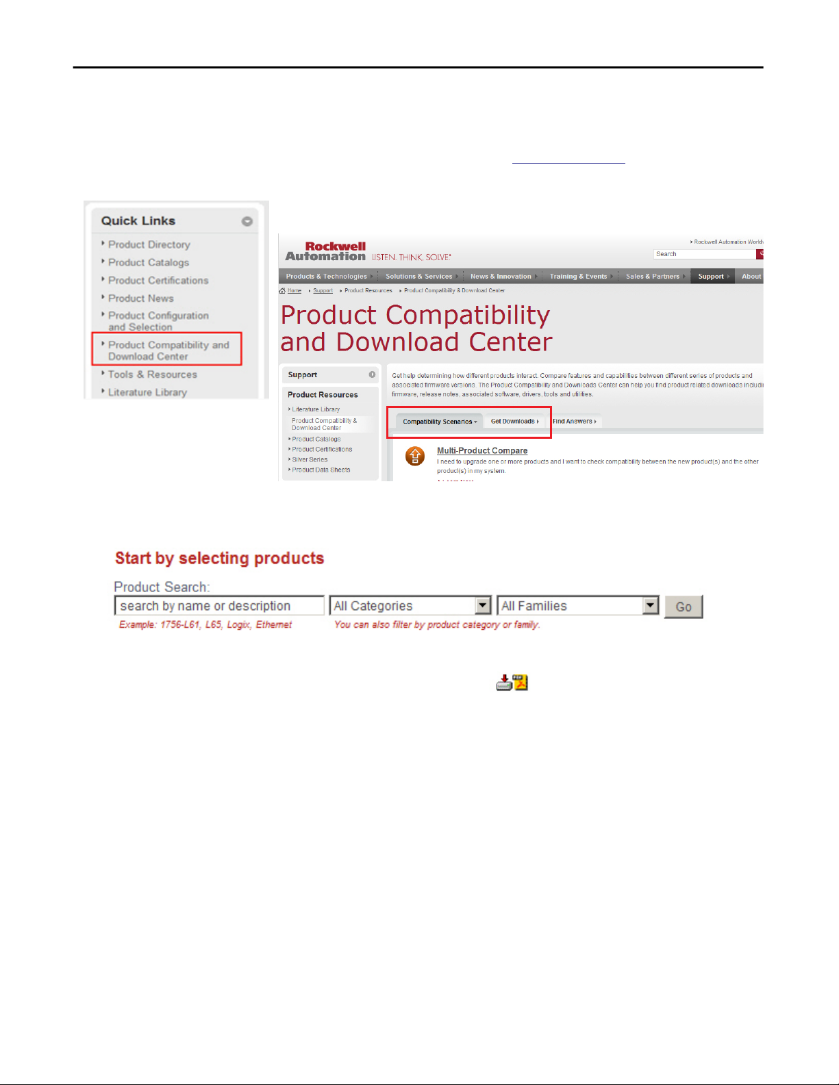
Access Product Release Notes
Product release notes are available online within the Product Compatibility and
Download Center.
1. From the Quick Links list on
Compatibility and Download Center.
2. From the Compatibility Scenarios tab or the Get Downloads tab, search
for and choose your product.
http://www.ab.com, choose Product
3. Click the download icon to access product release notes.
12 Rockwell Automation Publication 1783-UM004E-EN-P - June 2014
Page 13

Preface
Additional Resources
These documents contain additional information concerning related products
from Rockwell Automation.
Resource Description
Stratix Ethernet Managed Switches Technical Data,
publication
Ethernet Design Considerations Reference Manual,
publication
Device Manager Web interface online help (provided with
the switch)
Industrial Automation Wiring and Grounding Guidelines,
publication
Product Certifications website,
1783-TD001
ENET-RM002
1770-4.1
http://www.ab.com Provides declarations of conformity, certificates, and
Provides specification information for the switches.
Provides information about implementing a system
based on the EtherNet/IP platform.
Provides context-sensitive information on configuring
and using the switch, including system messages.
Provides general guidelines for installing a Rockwell
Automation industrial system.
other certification details.
You can view or download publications at
http:/www.rockwellautomation.com/literature/. To order paper copies of
technical documentation, contact your local Allen-Bradley distributor or
Rockwell Automation sales representative.
For information on additional software features or further configuration, see
these Cisco publications at
http://www.Cisco.com:
• Cisco IE-2000 Command Line Reference Manual
• Cisco IE-2000 Software Configuration Guide
• Cisco IE-2000 Switch System Message Guide
Rockwell Automation Publication 1783-UM004E-EN-P - June 2014 13
Page 14

Preface
Notes:
14 Rockwell Automation Publication 1783-UM004E-EN-P - June 2014
Page 15

About the Switches
Topic Page
Switch Catalog Numbers 16
Switch Software Features 17
Stratix 5700 Switch Dimensions 18
ArmorStratix 5700 Switch Dimensions 21
Switch Front Panel 22
Switch Hardware Features 22
SD Card 23
Switch Memory Allocation 25
Device Manager Web Interface 26
Studio 5000 Environment 27
Cisco Network Assistant 27
Command Line Interface 28
Chapter 1
Stratix 5700 Ethernet managed switches provide a secure switching infrastructure
for harsh environments. You can connect these switches to network devices such
as servers, routers, and other switches. In industrial environments, you can
connect Ethernet-enabled industrial communication devices, including
programmable logic controllers (PLCs), human-machine interfaces (HMIs),
drives, sensors, and I/O.
Rockwell Automation Publication 1783-UM004E-EN-P - June 2014 15
Page 16

Chapter 1 About the Switches
Switch Catalog Numbers
Catalog Number Description
Stratix 5700 Switches
1783-BMS4S2SGL 6 SFP-port (4 Ethernet ports; 2 Gigabit ports) managed switch; lite firmware
1783-BMS4S2SGA 6 SFP-port (4 Ethernet por ts; 2 Gigabit ports) managed switch; full firmware
1783-BMS06SL 6-port (4 Ethernet ports; 2 SFP slots) managed switch; lite firmware
1783-BMS06SA 6-port (4 Ethernet ports; 2 SFP slots) managed switch; full firmware
1783-BMS06TL 6-port (6 Ethernet ports) managed switch; lite firmware
1783-BMS06TA 6-port (6 Ethernet ports) managed switch; full firmware
1783-BMS06SGL 6-port (4 Ethernet ports; 2 SFP Gigabit slots) managed switch; lite firmware
1783-BMS06SGA 6-port (4 Ethernet ports; 2 SFP Gigabit slots) managed switch; full firmware
1783-BMS06TGL 6-port (4 Ethernet ports; 2 Gigabit ports) managed switch; full firmware
1783-BMS06TGA 6-port (4 Ethernet ports; 2 Gigabit ports) managed switch; full firmware
1783-BMS10CL 10-port (8 Ethernet ports; 2 combo ports) managed switch; lite firmware
1783-BMS10CA 10-port (8 Ethernet ports; 2 combo ports) managed switch; full firmware
1783-BMS10CGL 10-port (8 Ethernet ports; 2 combo Gigabit ports) managed switch; lite firmware
1783-BMS10CGA 10-port (8 Ethernet ports; 2 combo Gigabit ports) managed switch; full firmware
1783-BMS10CGN 10-port (8 Ethernet ports; 2 combo Gigabit ports) managed switch; full firmware; network address translation (NAT)
1783-BMS10CGP 10-port (8 Ethernet ports; 2 combo Gigabit por ts) managed switch; full firmware; PTP
1783-BMS12T4E2CGNK 18-port (12 Ethernet ports; 4 PoE/PoE+ ports; 2 combo Gigabit ports) managed switch; full firmware; NAT; conformal coating
1783-BMS12T4E2CGP 18-port (12 Ethernet ports; 4 PoE/PoE+ ports; 2 combo Gigabit ports) managed switch; full firmware, PTP
1783-BMS12T4E2CGL 18-port (12 Ethernet ports; 4 PoE/PoE+ ports; 2 combo Gigabit ports) managed switch; lite firmware
1783-BMS20CL 20-port (16 Ethernet ports; 2 SFP slots; 2 combo ports) managed switch; lite firmware
1783-BMS20CA 20-port (16 Ethernet ports; 2 SFP slots; 2 combo ports) managed switch; full firmware
1783-BMS20CGL 20-port (16 Ethernet ports; 2 SFP slots; 2 combo Gigabit ports) managed switch; lite firmware
1783-BMS20CGN 20-port (16 Ethernet ports; 2 SFP slots; 2 combo Gigabit ports) managed switch; full firmware; NAT
1783-BMS20CGP 20-port (16 Ethernet ports; 2 SFP slots; 2 combo Gigabit por ts) managed switch; full firmware; PTP
1783-BMS20CGPK 20-port (16 Ethernet por ts; 2 SFP slots; 2 combo Gigabit ports) managed switch; full firmware; PTP; conformal coating
ArmorStratix™ 5700 Switches
1783-ZMS8TA 8-port (8 Ethernet ports) managed switch; full firmware
1783-ZMS16TA 16-por t (16 Ethernet ports) managed switch; full firmware
1783-ZMS24TA 24-por t (24 Ethernet ports) managed switch; full firmware
1783-ZMS4T4E2TGP 10-port (4 Ethernet ports; 4 PoE/PoE+ ports; 2 Gigabit ports) managed switch; full firmware; Precision Time Protocol (PTP)
1783-ZMS8T8E2TGP 18-port (8 Ethernet ports; 8 PoE/PoE+ ports; 2 Gigabit ports) managed switch; full firmware; PTP
SFP Modules
1783-SFP100FX 100BASE-FX multi-mode fiber transceiver
1783-SFP1GSX 1000BASE-SX multi-mode fiber transceiver
1783-SFP100LX 100BASE-LX single-mode fiber transceiver
1783-SFP1GLX 1000BASE-LX single-mode fiber transceiver
These switches are available with either lite or full firmware.
16 Rockwell Automation Publication 1783-UM004E-EN-P - June 2014
Page 17

Catalog Number Description
Power Supply
1606-XL series (recommended)
1606-XLP series (recommended) or equivalent
SD Card
1784-SD1 1 GB Industrial SD card
Class 2, 24V DC output power supplies
About the Switches Chapter 1
Switch Software Features
Feature Lite Firmware Full Firmware
CIP Sync (IEEE 1588) Separate option
Resilient Ethernet Protocol (REP)
FlexLinks
Quality of Service (QoS)
STP, RSTP, MST (instances) 64 128
IGMP Snooping with querier
VLANs with trunking 64 255
EtherChannel (link aggregation)
Port Threshold (Storm Control and Traffic Shaping)
IPv6 support
Access Control Lists (ACL)
Static and interVLAN routing
CIP port control and fault detection
MAC ID Port security
IEEE 802.1x security
TACACS+, RADIUS authentication
Encryption (SSH, SNMPv3, HTTPS) Separate IOS firmware available as a separate catalog item
Port mirroring
Syslog
Broken wire detection
Duplicate IP address detection
SNMP
Smartports
DHCP per port
Command line interface (CLI)
These software features are available with the Stratix 5700 switches.
••
•
•
••
•
•
•
•
•
••
•
•
••
••
••
••
•
••
••
••
••
Rockwell Automation Publication 1783-UM004E-EN-P - June 2014 17
Page 18
Chapter 1 About the Switches
Feature Lite Firmware Full Firmware
Compatible with Cisco tools: Cisco Network Assistant
(CNA); CiscoWorks
EtherNet/IP (CIP) interface
••
••
Network address translation (NAT) Separate option
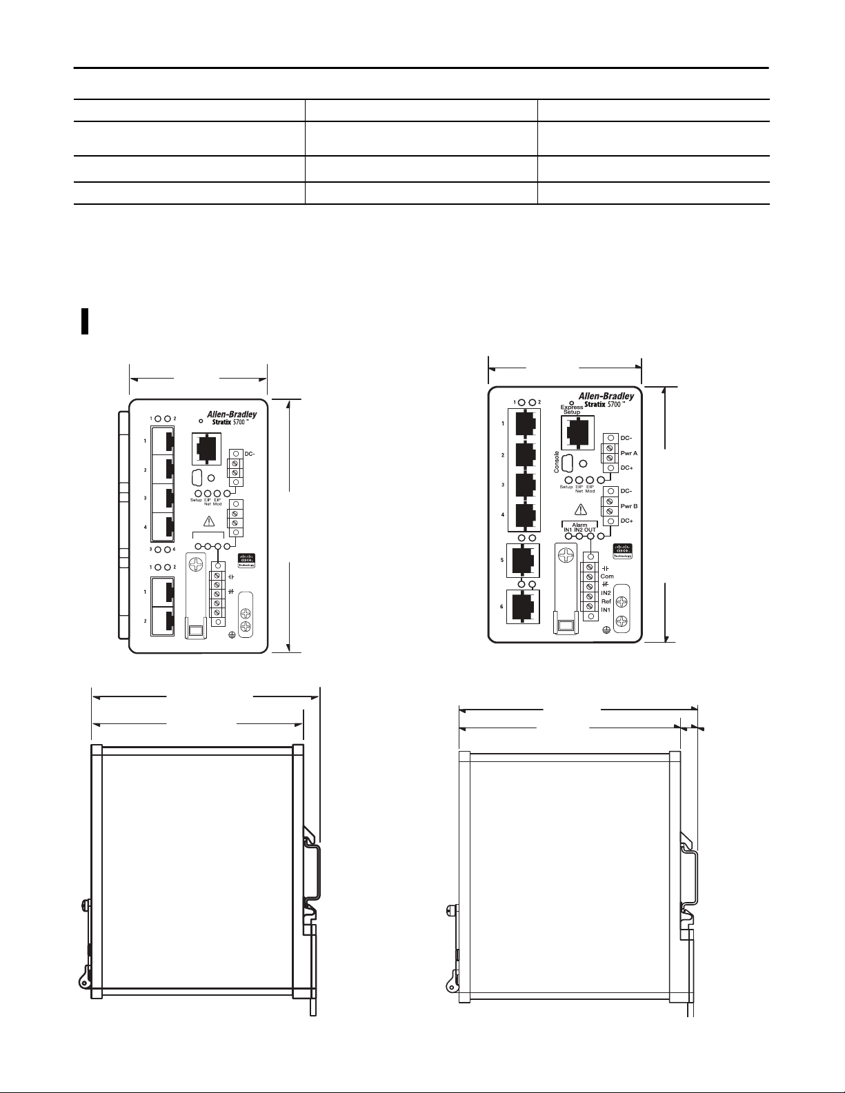
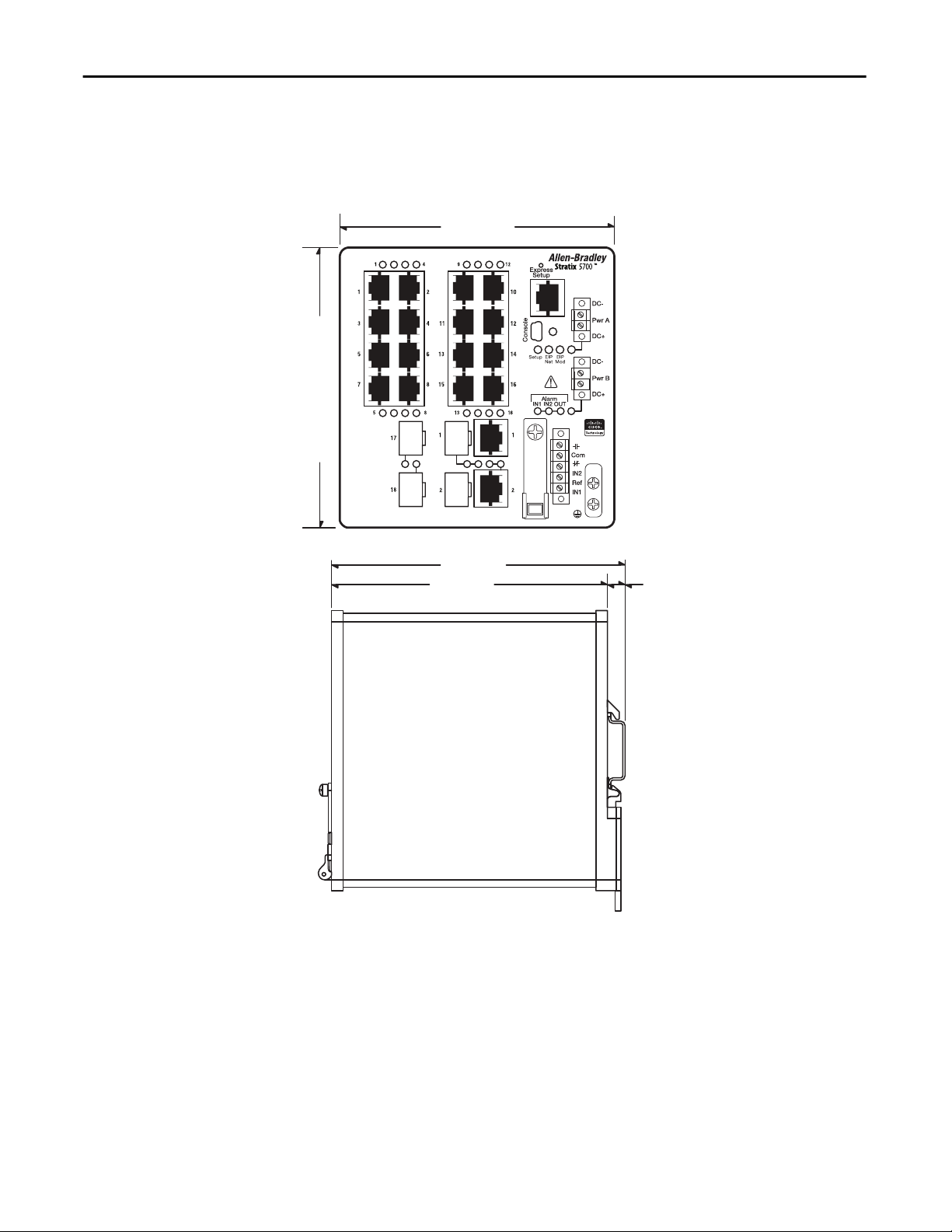
Stratix 5700 Switch Dimensions
6 SFP-port Switches
1783-BMS4S2SGL, 1783-BMS4S2SGA
8.00 cm
(3.15 in.)
Express
Setup
Console
Alarm
IN1 IN2 OUT
These diagrams are representative of the switches. Actual faceplates vary
depending on the catalog number.
6-port Switches
1783-BMS06SL, 1783-BMS06SA, 1783-BMS06TL, 1783-BMS06TA,
1783-BMS06SGL, 1783-BMS06SGA, 1783-BMS06TGL, 1783-BMS06TGA
7.48 cm
(2.94 in.)
Pwr A
DC+
DC-
12.95 cm
Pwr B
(5.1 in.)
DC+
Com
IN2
Ref
IN1
12.95 cm
(5.1 in.)
12.19 cm
(4.8 in.)
11.45 cm
0.75 cm
(0.29 in.)
(4.51 in.)
18 Rockwell Automation Publication 1783-UM004E-EN-P - June 2014
11.67 cm
(4.59 in.)
10.92 cm
(4.3 in.)
0.75 cm
(0.29 in.)
Page 19
About the Switches Chapter 1
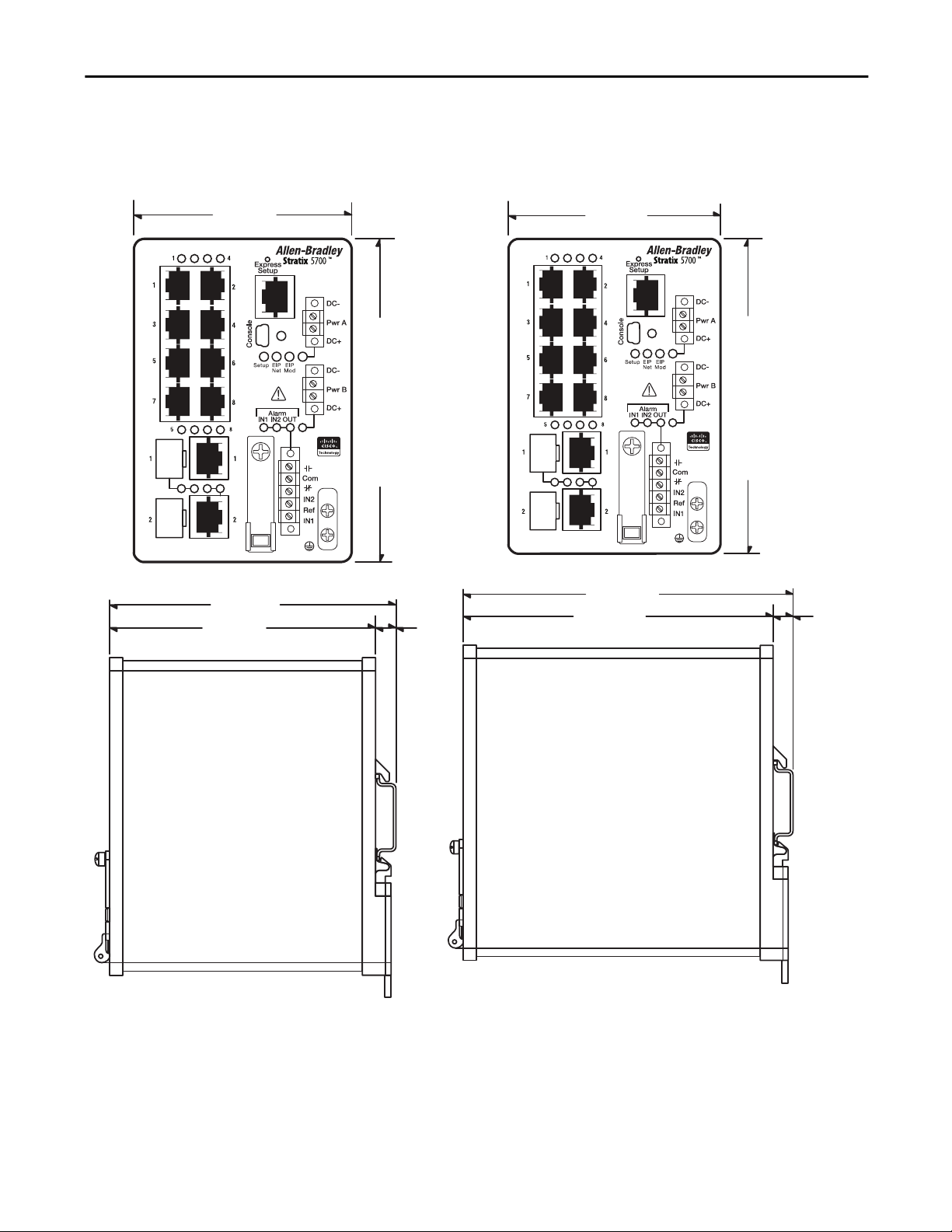
10-port Switches
1783-BMS10CL, 1783-BMS10CA,
1783-BMS10CGL, 1783-BMS10CGA
9.14 cm
(3.6 in.)
11.67 cm
(4.59 in.)
10.92 cm
(4.3 in.)
12.95 cm
(5.1 in.)
0.75 cm
(0.29 in.)
10-port Switch
1783-BMS10CGP, 1783-BMS10CGN
9.14 cm
(3.6 in.)
13.58 cm
(5.345 in.)
12.83 cm
(5.05 in.)
12.95 cm
(5.1 in.)
0.75 cm
(0.29 in.)
Rockwell Automation Publication 1783-UM004E-EN-P - June 2014 19
Page 20
Chapter 1 About the Switches
18- and 20-port Switches
1783-BMS12T4E2CGNK, 1783-BMS12T4E2CGP, 1783-BMS12T4E2CGL,
1783-BMS20CL, 1783-BMS20CA, 1783-BMS20CGL, 1783-BMS20CGP,
1783-BMS20CGN, 1783-BMS20CGPK
12.70 cm
(5.0 in.)
12.95 cm
(5.1 in.)
13.58 cm
(5.345 in.)
12.83 cm
(5.05 in.)
0.75 cm
(0.29 in.)
20 Rockwell Automation Publication 1783-UM004E-EN-P - June 2014
Page 21
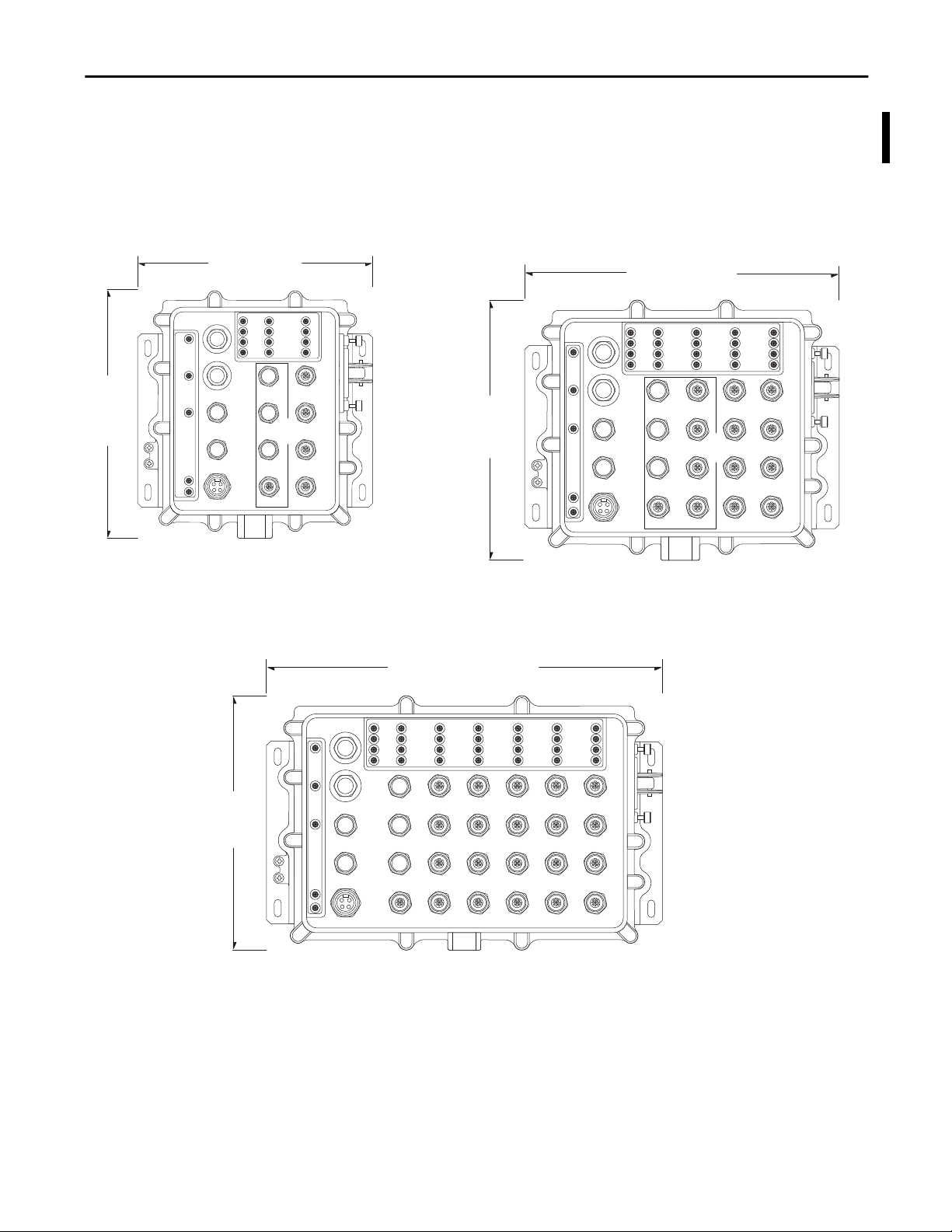
ArmorStratix 5700 Switch Dimensions
About the Switches Chapter 1
24.38 cm
(9.6 in.)
8-port Switches
1783-ZMS8TA, 1783-ZMS4T4E2TGP
23.75 cm
(9.35 in.)
24-port Switch
1783-ZMS24TA
16-port Switches
1783-ZMS16TA, 1783-ZMS8T8E2TGP
30.09 cm
(11.85in.)
24.38 cm
(9.6 in.)
32492
32493
37.46 cm
(14.75in.)
24.38 cm
(9.6 in.)
32494
Rockwell Automation Publication 1783-UM004E-EN-P - June 2014 21
Page 22
Chapter 1 About the Switches
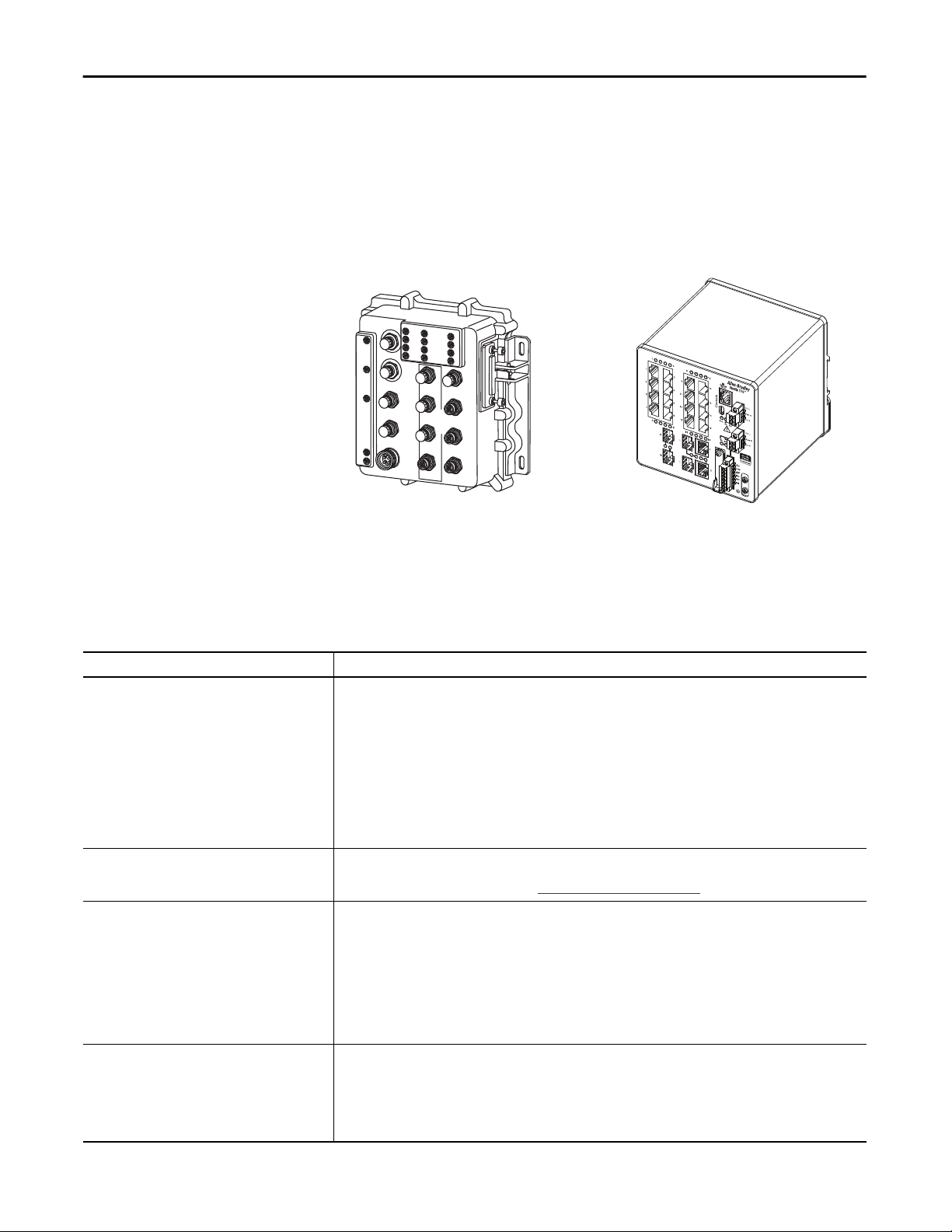
Switch Front Panel
The switch front panel contains the ports, status indicators, and power and relay
connectors.
These diagrams are representative of the switch front panels. Actual front panels
vary depending on the catalog number.
ArmorStratix 5700 Switch
32495
Stratix 5700 Switch
32276-M
Switch Hardware Features
Feature Description
Power and relay connectors You connect the DC power and alarm signals to the switch through two front panel connectors. One connector provides
Console port For configuring, monitoring, and managing the switch, you can connect a switch to a computer through the console port
Dual-purpose uplink ports The two dual-purpose uplink ports available on some models can each be configured for RJ45 (copper) or SFP (fiber) media
10/100 ports You can set the 10/100 ports to operate at 10 or 100 Mbps, full-duplex or half-duplex. You can also set these ports for
These hardware features are available with the switches.
primary DC power (Pwr A) and a second connector (Pwr B) provides secondary power. The two connectors are physically
identical and are on the right side of the front panel.
The 6-pin alarm connector provides an interface for an output alarm relay and two input alarms. The output alarm can be
activated for environmental, power supply, and port status alarm conditions and can be configured to indicate an alarm
with one normally open and one normally closed (form C) contact. From the CLI, you can configure the output alarm to be
normally energized or normally de-energized. The input alarm terminals can be used to activate alarms for any conditions
external to the switch.
The switch can operate with a single power source or with dual power sources. When both power sources are operational,
the switch draws power from the DC source with the higher voltage. If one of the two power sources fail, the other
continues to power the switch.
and a RJ45-to-DB-9 adapter cable or a mini USB cable (neither cables are supplied with the switch). The mini USB driver is
available in the firmware download section at
types. Only one of these connections in each of the dual-purpose ports can be active at a time. If both ports are connected,
the SFP module port has priority.
You can set the copper RJ45 ports to operate at 10, 100, or 1000 Mbps (1000Mbps is not supported on all modules with
combo ports), full-duplex or half-duplex. You can configure them as fixed 10, 100, or 1000 Mbps (Gigabit) Ethernet ports
and can configure the duplex setting.
You can use approved Gigabit (or 100 Mbps) Ethernet SFP modules to establish fiber-optic connections to other switches.
These transceiver modules are field-replaceable, providing the uplink interfaces when inserted in an SFP module slot. You
use fiber-optic cables with LC connectors to connect to a fiber-optic SFP module. These ports operate only in full-duplex.
speed and duplex autonegotiation in compliance with IEEE 802.3-2002. (The default setting is autonegotiate.)
When set for autonegotiation, the port senses the speed and duplex settings of the attached device. If the connected
device also supports autonegotiation, the switch port negotiates the best connection (that is, the fastest line speed that
both devices support and full-duplex transmission if the attached device supports it) and configures itself accordingly. In
all cases, the attached device must be within 100 m (328 ft) of the switch.
http://www.rockwellautomation.com.
22 Rockwell Automation Publication 1783-UM004E-EN-P - June 2014
Page 23

About the Switches Chapter 1
Feature Description
100BASE-FX/SX ports The IEEE 802.3-2002 100BASE-FX ports provide full-duplex, 100 Mbps connectivity over multi-mode fiber (MMF) cables.
1000BASE-FX/SX ports The IEEE 802.3-2002 1000BASE-FX ports on some models provide full-duplex, 1 Gbps connectivity over multi-mode fiber
PoE ports The PoE ports available on some models can be configured for PoE (IEEE 802.3af) or PoE+ (IEEE 802.3at Type 2):
Auto-MDIX When connecting the switch to workstations, servers, and routers, straight-through cables are normally used. However,
These ports use a built-in, small-form-factor fixed (SFF) fiber-optic transceiver module that accepts a dual LC connector.
(MMF) cables. These ports use a built-in, small-form-factor fixed (SFF) fiber-optic transceiver module that accepts a dual LC
connector.
• For PoE configuration, the PoE ports require an external, 2-wire 48V DC input power source.
• For PoE+ configuration, the PoE ports require an external, 2-wire 54V DC input power source.
the automatic medium-dependent interface crossover (auto-MDIX) feature of the switch is enabled by default and
automatically reconfigures the ports to use either a straight-through or crossover cable type.
The Auto-MDIX feature is enabled by default. When the auto-MDIX feature is enabled, the switch detects the required
cable type (straight-through or crossover) for copper Ethernet connections and configures the interfaces accordingly.
You can use the command-line interface (CLI) to disable the auto-MDIX feature. See the online help for more information.
Configuration Files
SD Card
The switch configuration file (config.txt) is in ASCII human-readable format.
This configuration file is stored in nonvolatile memory and is read into the
switches’ Random Access Memory (RAM) as the running configuration when
the switch is powered up. When any changes are made to the configuration, the
changes immediately take effect in the running configuration. The Device
Manager Web interface and the Add-on Profile (AOP) for the Logix Designer
application automatically write changes to flash memory to be retained for the
next power-up cycle. Any changes made via the CLI must be manually written to
flash memory to be retained for the next power-up cycle.
The switch is equipped with a slot for an optional Secure Digital (SD) card, in
addition to the onboard flash memory. The SD card can be used instead of
onboard flash memory to easily restore a switch configuration in case of failure or
to easily duplicate configurations when you are deploying a new network.
If the SD card is installed on the switch, the switch starts the IOS and
configuration present on the SD card. If the SD card is not installed, or files are
not present, the switch reads the on-board boot parameters and restarts from the
specified IOS image on the onboard flash memory.
You must use the SD card available from Rockwell Automation (catalog number
1784-SD1) with the switch.
ATTENTION: Rockwell Automation reserves the right to withhold support if a
non-Rockwell SD card is used in this product.
Rockwell Automation Publication 1783-UM004E-EN-P - June 2014 23
Page 24
Chapter 1 About the Switches
If you start from the SD card and then remove it while the switch is running, the
following conditions apply:
• The Device Manager Web interface is no longer be accessible.
• Changes made by using the CLI or the AOP take effect, but are not saved
when the switch is restarted.
• If the SD card is reinserted into the slot, changes are not saved to the card
unless new changes are made. Then the entire configuration is saved to the
card.
ATTENTION: SD cards commonly have a physical read-only lock switch. If this
switch is engaged, the switch starts from the SD card successfully. Changes
made by using the CLI, AOP, or Device Manager Web interface take effect, but
are not saved when the switch is restarted.
SD Card Sync
You can use the Device Manager Web interface or the AOP for the
Logix Designer application to synchronize the SD card for configuration and
IOS updates. The configuration synchronization process synchronizes
config.text and vlan.dat from the chosen source to the chosen destination.
The IOS image synchronization process synchronizes the existing bootable IOS
image from the chosen source to the chosen destination. This process takes
approximately five minutes to complete.
If other files, such as backup configurations, are present on the SD card, they are
not synchronized.
ATTENTION: When synchronizing, be aware of your start-up source, so that you
know which way to synchronize. Device Manager provides this information on
the SD Card Sync tab. You can overwrite your desired configuration if you
synchronize in the wrong direction.
24 Rockwell Automation Publication 1783-UM004E-EN-P - June 2014
Page 25

About the Switches Chapter 1
Switch Memory Allocation
The following table provides details on default memory allocation for the
switches.
You can use SDM templates to configure system resources in the switch to
optimize support for specific features, depending on how the switch is used in the
network. You can select a template to provide maximum system usage for some
functions; for example, use the default template to balance resources, and use
access template to obtain maximum ACL usage. To allocate hardware resources
for different usages, the switch SDM templates prioritize system resources to
optimize support for certain features.
The following SDM Templates are available:
• Default
• Routing
• Dual IPv4 and IPv6
Consider using the routing template if you enable static routing, or if you have
more than 180 IGMP groups or multicast routes. Consider using the Dual IPv4
and IPv6 template if you are using IPv6.
You can select SDM templates for IP version 4 (IPv4) to optimize these features.
Feature Memory Alloc ation
Default Routing Dual IPv4 and IPv6
Unicast MAC addresses 8 K 4 K 7.5 K
IPv4 IGMP groups + multicast routes 0.25 K 0.25 K 0.25 K
IPv4 unicast routes 0 4.25 K 0
IPv6 multicast groups 0 0 0.375 K
Directly connected IPv4 hosts 0 4 K
Directly connected IPv6 addresses 0 0 o
Indirect IPv4 routes 0 0.25 K
Indirect IPv6 routes 0 0 0
IPv4 policy based routing aces 0 0
IPv4/MAC QoS aces 0.375 K 0.375 K 0.375 K
IPv4/MAC security aces 0.375 K 0.375 K 0.375 K
IPv6 policy based routing aces 0 0 0
IPv6 QOS aces 0 0 0
IPv6 security aces 0 0 0.125 K
Rockwell Automation Publication 1783-UM004E-EN-P - June 2014 25
Page 26

Chapter 1 About the Switches
Device Manager Web Interface
You can manage the switch by using the Device Manager Web interface to
configure and monitor the switch. The Device Manager Web interface is a
graphical device management tool for configuring, monitoring, and
troubleshooting individual switches.
The Device Manager Web interface displays real-time views of switch
configuration and performance. It simplifies configuration tasks with features
such as Smartports to quickly set up the switch and its ports. It uses graphical,
color-coded displays, such as the Front Panel view, graphs, and animated
indicators to simplify monitoring tasks. It provides alert tools to help you to
identify and to solve networking problems.
You can display the Device Manager Web interface from anywhere in your
network through a Web browser such as Microsoft Internet Explorer.
Hardware Requirements
Attribute Requirement
Processor speed 1 GHz or faster (32-bit or 64-bit)
RAM 1 GB (32-bit) or 2 GB (64-bit)
Available hard drive space 16 GB (32-bit) or 20 GB (64-bit)
Number of colors 256
Resolution 1024 x 768
Font size Small
Software Requirements
Web Browser Version
Microsoft Internet Explorer 9.0, 10.0, or 11.0 with JavaScript enabled
Mozilla Firefox 25 or 26 with JavaScript enabled
The Device Manager Web interface verifies the browser version when starting a
session to be sure that the browser is supported.
TIP
So that the Device Manager Web interface runs properly, disable any
pop-up blockers or proxy settings in your browser software and any
wireless clients running on your computer or laptop.
26 Rockwell Automation Publication 1783-UM004E-EN-P - June 2014
Page 27

About the Switches Chapter 1
Studio 5000 Environment
Cisco Network Assistant
You can manage the switch by using the Logix Designer application in the
Studio 5000 environment. The Logix Designer application is IEC 61131-3
compliant and offers relay ladder, structured text, function block diagram, and
sequential function chart editors for you to develop application programs.
Hardware Requirements
Attribute Requirement
Processor speed Pentium II 450 MHz min
Pentium III 733 MHz (or better) recommended
RAM 128 MB min
256 MB recommended
Free hard drive space 3 GB
Optical drives DVD
Video requirements 256-color VGA graphics adapter
800 x 600 min resolution (True Color 1024 x 768 recommended)
Resolution 800 x 600 min resolution (True Color 1024 x 768 recommended)
Cisco Network Assistant is a Web interface that you download from Cisco’s
website and run on your computer. It offers advanced options for configuring and
monitoring multiple devices, including switches, switch clusters, switch stacks,
routers, and access points.
To use the software, follow these steps.
1. Go to
http://www.cisco.com/go/NetworkAssistant.
You must be a registered user, but you need no other access privileges.
2. Find the Network Assistant installer.
3. Download the Network Assistant installer, and run it.
You can run it directly from the Web if your browser offers this choice.
4. When you run the installer, follow the displayed instructions.
5. In the final panel, click Finish to complete the Network Assistant
installation.
6. See the Network Assistant online help for more information.
Rockwell Automation Publication 1783-UM004E-EN-P - June 2014 27
Page 28

Chapter 1 About the Switches
Command Line Interface
You can manage the switch from the command line interface (CLI) by
connecting your personal computer directly to the switch console port or
through the network by using Telnet.
To access the CLI through the console port, follow these steps.
1. Connect to the console port in one of these ways:
• Use a RJ45-to-DB-9 adapter cable (not supplied with the switch) to
connect to the standard 9-pin serial port on a personal computer.
• Use a standard mini-USB cable (not supplied with the switch) to
connect to the mini-USB port on a personal computer.
• If you are using the USB cable, download the drivers for your
Microsoft Windows computer from
http://www.rockwellautomation.com.
2. Connect the other end of the cable to the console port on the switch.
WARNING: The console port is intended only for temporary local
programming purposes and not intended for permanent connection. If
you connect or disconnect the console cable with power applied to this
module or the programming device on the other end of the cable, an
electrical arc can occur. This could cause an explosion in hazardous
location installations. Be sure that power is removed or the area is
nonhazardous before proceeding.
3. Start a terminal-emulation program on the personal computer.
4. Configure the personal computer terminal emulation software for
9600 bps, 8 data bits, no parity, 1 stop bit, and no flow control.
28 Rockwell Automation Publication 1783-UM004E-EN-P - June 2014
Page 29

Switch Installation
Topic Page
Stratix 5700 Switch Installation 30
Installation Guidelines 31
Install or Remove the SD Card (optional) 33
Verify Switch Operation 34
Mount the Switch on a DIN Rail 36
Remove the Switch from the DIN Rail 38
Ground the Switch 38
Wire the Switch DC Power Source 40
Attach the Switch Power Connectors 43
Wire the Power over Ethernet DC Power Source 44
Attach the PoE Power Connector 46
Install an SFP Module (optional) 46
Remove SFP Modules from SFP Module Slots 48
Wire the External Alarms 49
Attach the Alarm Relay Connector to the Switch 52
Connect to 10/100 and 10/100/1000 Ports 52
Connect to 10BASE-T, 100BASE-TX, or 1000BASE-T Ports 53
Connect to PoE Ports 54
Connect to SFP Modules 55
Connect to a Dual-purpose Port 56
ArmorStratix 5700 Switch Installation 57
Installation Guidelines 57
Install or Remove the SD Card (optional) 59
Verify Switch Operation 60
Mount the Switch 61
Ground the Switch 62
Connect the Switch to a DC Power Source 64
Wire External Alarms 65
Connect to 10/100 and 10/100/1000 Ports 66
Connect to PoE Ports 66
Set Up the Switch Initially with Express Setup 67
Chapter 2
Rockwell Automation Publication 1783-UM004E-EN-P - June 2014 29
Page 30
Chapter 2 Switch Installation
Stratix 5700 Switch Installation
ATTENTION: Environment and Enclosure
This equipment is intended for use in a Pollution Degree 2 industrial environment, in overvoltage Category II applications (as defined
in IEC 60664-1), at altitudes up to 2000 m (6562 ft) without derating.
This equipment is not intended for use in residential environments and may not provide adequate protection to radio communication
services in such environments.
This equipment is supplied as open-type equipment. It must be mounted within an enclosure that is suitably designed for those
specific environmental conditions that will be present and appropriately designed to prevent personal injury resulting from
accessibility to live parts. The enclosure must have suitable flame-retardant properties to prevent or minimize the spread of flame,
complying with a flame spread rating of 5VA or be approved for the application if nonmetallic. The interior of the enclosure must be
accessible only by the use of a tool. Subsequent sections of this publication may contain additional information regarding specific
enclosure type ratings that are required to comply with certain product safety certifications.
In addition to this publication, see the following:
• Industrial Automation Wiring and Grounding Guidelines, publication
• NEMA Standard 250 and IEC 60529, as applicable, for explanations of the degrees of protection provided by enclosures
1770-4.1, for additional installation requirements
North American Hazardous Location Approval
The following information applies when operating this equipment in
hazardous locations.
Products marked "CL I, DIV 2, GP A, B, C, D" are suitable for use in Class I Division 2 Groups
A, B, C, D, Hazardous Locations and nonhazardous locations only. Each product is supplied
with markings on the rating nameplate indicating the hazardous location temperature
code. When combining products within a system, the most adverse temperature code
(lowest "T" number) may be used to help determine the overall temperature code of the
system. Combinations of equipment in your system are subject to investigation by the
local Authority Having Jurisdiction at the time of installation.
WARNING: EXPLOSION HAZARD
• Do not disconnect equipment unless power has
been removed or the area is known to be
nonhazardous.
• Do not disconnect connections to this
equipment unless power has been removed or
the area is known to be nonhazardous. Secure
any external connections that mate to this
equipment by using screws, sliding latches,
threaded connectors, or other means provided
with this product.
• Substitution of components may impair
suitability for Class I, Division 2.
• If this product contains batteries, they must only
be changed in an area known to be
nonhazardous.
Informations sur l’utilisation de cet équipement en environnements
dangereux.
Les produits marqués "CL I, DIV 2, GP A, B, C, D" ne conviennent qu'à une utilisation en
environnements de Classe I Division 2 Groupes A, B, C, D dangereux et non dangereux.
Chaque produit est livré avec des marquages sur sa plaque d'identification qui indiquent
le code de température pour les environnements dangereux. Lorsque plusieurs produits
sont combinés dans un système, le code de température le plus défavorable (code de
température le plus faible) peut être utilisé pour déterminer le code de température
global du système. Les combinaisons d'équipements dans le système sont sujettes à
inspection par les autorités locales qualifiées au moment de l'installation.
WARNING: RISQUE D’EXPLOSION
• Couper le courant ou s'assurer que
l'environnement est classé non dangereux avant
de débrancher l'équipement.
• Couper le courant ou s'assurer que
l'environnement est classé non dangereux avant
de débrancher les connecteurs. Fixer tous les
connecteurs externes reliés à cet équipement à
l'aide de vis, loquets coulissants, connecteurs
filetés ou autres moyens fournis avec ce produit.
• La substitution de composants peut rendre cet
équipement inadapté à une utilisation en
environnement de Classe I, Division 2.
• S'assurer que l'environnement est classé non
dangereux avant de changer les piles.
30 Rockwell Automation Publication 1783-UM004E-EN-P - June 2014
Page 31

Switch Installation Chapter 2
European Hazardous Location Approval
The following applies when the product bears the Ex Marking.
This equipment is intended for use in potentially explosive atmospheres as defined by European Union Directive 94/9/EC and has been found to comply with the Essential Health and
Safety Requirements relating to the design and construction of Category 3 equipment intended for use in Zone 2 potentially explosive atmospheres, given in Annex II to this Directive.
Compliance with the Essential Health and Safety Requirements has been assured by compliance with EN 60079-15 and EN 60079-0.
ATTENTION: This equipment is not resistant to sunlight or other sources of UV radiation.
WARNING:
• This equipment shall be mounted in an ATEX-certified enclosure with a minimum ingress protection rating of at least IP54 (as
defined in IEC60529) and used in an environment of not more than Pollution Degree 2 (as defined in IEC 60664-1) when applied in
Zone 2 environments. The enclosure must have a tool-removable cover or door.
• This equipment shall be used within its specified ratings defined by Rockwell Automation.
• Provision shall be made to prevent the rated voltage from being exceeded by transient disturbances of more than 140% of the
rated voltage when applied in Zone 2 environments.
• Secure any external connections that mate to this equipment by using screws, sliding latches, threaded connectors, or other
means provided with this product.
• Do not disconnect equipment unless power has been removed or the area is known to be nonhazardous.
Installation Guidelines
WARNING: If you connect or disconnect Ethernet cables with power applied to
this module or any device on the network, an electrical arc can occur. This could
cause an explosion in hazardous location installations.
Be sure that power is removed or the area is nonhazardous before proceeding.
ATTENTION: The alarm port cables are not to exceed 10.0 m (32.81 ft).
At the end of its life, this equipment should be collected separately from any
unsorted municipal waste.
When determining where to place the switch, observe these guidelines:
• Airflow around the switch is unrestricted. To prevent the switch from
overheating, observe the following minimum clearances:
– Top and bottom: 50.8 mm (2.0 in.)
– Sides: 50.8 mm (2.0 in.)
– Front: 50.8 mm (2.0 in.)
Rockwell Automation Publication 1783-UM004E-EN-P - June 2014 31
Page 32

Chapter 2 Switch Installation
• For 10/100 ports and 10/100/1000 ports, the cable length from a switch
to an attached device cannot exceed 100 m (328 ft).
• The fiber-optic cable length from a switch to an attached device cannot
exceed the distance specified in
Appendix C.
• For maximum noise immunity, shielded cables must be used on the RJ45
uplink ports (Gi1/1 and Gi1/2) on these switches:
– 1783-BMS06TGL
– 1783-BMS06TGA
– 1783-BMS10CGL
– 1783-BMS10CGA
– 1783-BMS10CGN
– 1783-BMS10CGP
– 1783-BMS12T4E2CGNK
– 1783-BMS12T4E2CGP
– 1783-BMS12T4E2CGL
– 1783-BMS20CGL
– 1783-BMS20CGN
– 1783-BMS20CGP
– 1783-BMS20CGPK
• Temperature surrounding the unit does not exceed 60 °C (140 °F).
IMPORTANT
When the switch is installed in an industrial enclosure, the
temperature within the enclosure is greater than normal room
temperature outside the enclosure.
The temperature inside the enclosure cannot exceed 140 °F (60 °C), the
maximum ambient enclosure temperature of the switch.
• Clearance to front and rear panels meets these conditions:
– Front-panel status indicators can be easily read.
– Access to ports is sufficient for unrestricted cabling.
– Front-panel direct current (DC) power connectors and the alarm relay
connector are within reach of the connection to the DC power source.
• Cabling is away from sources of electrical noise, such as radios, power lines,
and fluorescent lighting fixtures.
• Connect the unit to only a Class 2 DC power source.
ATTENTION: Do not wire more than 1 conductor on any single terminal.
32 Rockwell Automation Publication 1783-UM004E-EN-P - June 2014
Page 33

Switch Installation Chapter 2
Install or Remove the SD Card (optional)
WARNING: When you insert or remove the CompactFlash/SD memory card
while power is on, an electrical arc can occur. This can cause an explosion in
hazardous location installations.
Be sure that power is removed or the area is nonhazardous before proceeding.
To install or replace the SD card, follow these steps.
1. On the front of the switch, locate the door that protects the SD card slot.
2. Loosen the captive thumb screw at the top of the door by using a
screwdriver to open the door.
3. Install or remove the card:
• To install the card, slide it into the slot, and press it firmly in place until
it latches in the spring loaded mechanism. The card is keyed so that you
cannot fully insert it the wrong way.
•
32271-M
Rockwell Automation Publication 1783-UM004E-EN-P - June 2014 33
Page 34

Chapter 2 Switch Installation
• To remove the card, push it in and let it pop out via the spring-loaded
mechanism. Grasp the card top and pull it out. Place it in an antistatic
bag to protect it from static discharge.
Setup
EIP
EIP
Net
Mod
Alarm
IN1
IN2
OUT
32272-M
4. Close the guard door and fasten the captive screw by using a screwdriver to
keep the door in place.
Verify Switch Operation
Before installing the switch in its final location, power on the switch, and verify
that the switch powers up.
The time required for the switch to start up is directly related to your switch
configuration. Start time is negatively affected by such things as the following:
• Spanning Tree Learning mode
• Number of files or images in onboard flash memory
34 Rockwell Automation Publication 1783-UM004E-EN-P - June 2014
Page 35

Switch Installation Chapter 2
To test the switch, follow these steps.
1. Apply power to the switch.
To apply power to a switch that is directly connected to a DC power
source, locate the circuit breaker on the panel board that services the DC
circuit, and switch the circuit breaker to the ON position.
2. Verify the start-up sequence.
When you power on the switch, it automatically begins a start-up routine.
The System status indicator blinks green as the IOS software image loads.
If the routine fails, the System status indicator turns red.
IMPORTANT
Start-up failures are usually fatal to the switch. Contact your
Rockwell Automation representative immediately if your switch does
not complete the start sequence successfully.
IMPORTANT
You can disable boot fast and run the Power-on Self Test (POST) by
using the IOS CLI. See the appropriate documentation at
http://www.Cisco.com for more information.
3. After successfully running this test, do the following:
a. Turn off power to the switch.
b. Disconnect the cables.
c. Decide where you want to install the switch
Rockwell Automation Publication 1783-UM004E-EN-P - June 2014 35
Page 36

Chapter 2 Switch Installation
Mount the Switch on a DIN Rail
The switch ships with a spring-loaded latch on the rear panel for mounting on a
DIN rail.
WARNING: If you connect or disconnect console port cables with power
applied to this module or any device on the network, an electrical arc can occur.
This could cause an explosion in hazardous location installations.
Be sure that power is removed or the area is nonhazardous before proceeding.
WARNING: Do not use the USB-mini console port in hazardous locations.
ATTENTION: Prevent Electrostatic Discharge
This equipment is sensitive to electrostatic discharge, which can cause internal
damage and affect normal operation. Follow these guidelines when you handle
this equipment:
• Touch a grounded object to discharge potential static.
• Wear an approved grounding wriststrap.
• Do not touch connectors or pins on component boards.
• Do not touch circuit components inside the equipment.
• Use a static-safe workstation, if available.
• Store the equipment in appropriate static-safe packaging when not in use.
ATTENTION: This equipment is supplied as open type equipment. It must be
mounted within an enclosure suitably designed for those specific
environmental conditions and appropriately designed to prevent personal
injury resulting from accessibility to live parts. The interior of the enclosure
must be accessible only by using a tool.
The enclosure must meet IP 54 or NEMA type 4 minimum enclosure rating
standards.
ATTENTION: To prevent the switch from overheating, make sure these
minimum clearances:
• Top and bottom: 50.8 mm (2.0 in.)
• Exposed side (not connected to the module): 50.8 mm (2.0 in.)
• Front: 50.8 mm (2.0 in.)
ATTENTION: The console ports are intended for temporary local programming
purposes only and not intended for permanent connection.
The console port cables are not to exceed 3.0 m (9.84 ft) and must not contain
hubs.
36 Rockwell Automation Publication 1783-UM004E-EN-P - June 2014
Page 37

Switch Installation Chapter 2
ATTENTION: Under certain conditions, viewing the optical port may expose the
eye to hazard. When viewed under some conditions, the optical port may
expose the eye beyond the maximum permissible exposure recommendations.
ATTENTION: Class 1 laser product. Laser radiation is present when the system is
open and interlocks bypassed. Only trained and qualified personnel should be
allowed to install, replace, or service thisequipment.
ATTENTION: This product is grounded through the DIN rail to chassis ground.
Use zinc plated yellow-chromate steel DIN rail to assure proper grounding. The
use of other DIN rail materials (for example, aluminum or plastic) that can
corrode, oxidize, or are poor conductors, can result in improper or intermittent
grounding. Secure DIN rail to mounting surface approximately every 200 mm
(7.8 in.) and use end-anchors appropriately.
To attach the switch to a DIN rail, follow these steps.
1. Position the rear panel of the switch directly in front of the DIN rail,
making sure that the DIN rail fits in the space between the two hooks near
the top of the switch and the spring-loaded latch near the bottom.
2. Holding the bottom of the switch away from the DIN rail, place the two
hooks on the back of the switch over the top of the DIN rail.
32285-M
3. Push the switch toward the DIN rail to cause the spring loaded latch at the
bottom rear of the switch to move down and snap into place.
Rockwell Automation Publication 1783-UM004E-EN-P - June 2014 37
Page 38

Chapter 2 Switch Installation
Remove the Switch from the DIN Rail
To remove the switch from a DIN rail or a rack, follow these steps.
1. Remove power from the switch, and disconnect all cables and connectors
from the front panel of the switch.
2. Insert a tool, such as a flat-head screwdriver, in the slot at the bottom of the
spring-loaded latch and use it to release the latch from the DIN rail.
32286-M
Ground the Switch
For DC power connections, use UL- and CSA-rated, style 1007 or 1569
twisted-pair copper appliance wiring material (AWM) wire.
WARNING: If you connect or disconnect power or alarm wiring while the
field-side power is on, an electrical arc can occur. This could cause an explosion
in hazardous location installations. Be sure that power is removed or the area is
nonhazardous before proceeding.
ATTENTION: This equipment must be grounded. Never defeat the ground
conductor or operate the equipment in the absence of a suitably installed
ground conductor. Contact the appropriate electrical inspection authority or an
electrician if you are uncertain that suitable grounding is available.
This equipment is intended to be grounded to comply with emission and immunity
requirements. Make sure that the switch functional ground lug is connected to
earth ground during normal use.
ATTENTION: To make sure that the equipment is reliably connected to earth
ground, follow the grounding procedure instructions and use a suitable ring
terminal lug, such as Thomas & Betts part number 10RCR or equivalent.
38 Rockwell Automation Publication 1783-UM004E-EN-P - June 2014
Page 39

Switch Installation Chapter 2
ATTENTION: For proper grounding, you must always connect the power supply
functional-ground screw when connecting the power supply. You must provide
an acceptable grounding path for each device in your application. For more
information on proper grounding guidelines, refer to publication
1770-4.1,
Industrial Automation Wiring and Grounding Guidelines.
Use at least 4 mm2 (12 AWG) wire to connect to the external grounding screw.
The ground lug is not supplied with the switch. You can use one of the these
options:
• Single ring terminal
• Two single ring terminals
To ground the switch to earth ground, follow these steps. Be sure to follow any
grounding requirements at your site.
1. Use a Phillips screwdriver or a ratcheting torque screwdriver with a Phillips
head to remove the ground screw from the front panel of the switch.
Store the ground screw for later use.
2. Use the manufacturer’s guidelines to determine the wire length to be
stripped.
3. Insert the ground wire into the ring terminal lug and use a crimping tool to
crimp the terminal to the wire.
If you are using two ring terminals, repeat this action for the second ring
terminal.
32273-M
4. Slide the ground screw through the terminal.
Rockwell Automation Publication 1783-UM004E-EN-P - June 2014 39
Page 40

Chapter 2 Switch Installation
5. Insert the ground screw into the functional ground screw opening on the
front panel.
Ring Terminal Lug (single lug shown)
32276-M
6. Use a ratcheting torque screwdriver to tighten the ground screws and ring
terminal lugs to the switch front panel to 0.4 N
m (3.5 lbin).
Do not exceed the recommended torque.
7. Attach the other end of the ground wire to a grounded bare metal surface,
such as a ground bus, a grounded DIN rail, or a grounded bare rack.
Wire the Switch DC Power Source
To wire the DC power source for the switch, follow these steps.
ATTENTION: Before performing any of the following procedures, make sure
that power is removed from the DC circuit or the area is nonhazardous before
proceeding:
• This product is intended to be supplied by a Class 2 power source marked with
‘Class 2’ and rated from 12, 24, or 48V DC, 2.5 A.
• To comply with the CE Low Voltage Directive (LVD), this equipment must be
powered from a source compliant with the safety extra low voltage (SELV) or
protected extra low voltage (PELV).
• A readily accessible two-poled disconnect device must be incorporated in the
fixed wiring.
• This product relies on the building’s installation for short-circuit (overcurrent)
protection. Make sure that the protective device is rated not greater than 3 A.
• Installation of the equipment must comply with local and national electrical
codes.
• Allow only trained and qualified personnel to install, replace, or service this
equipment.
ATTENTION: For wire connections to the power and relay connector, you must
use UL- and CSA-rated, style 1007 or 1569 twisted-pair copper appliance wiring
material (AWM) wire.
40 Rockwell Automation Publication 1783-UM004E-EN-P - June 2014
Page 41

Switch Installation Chapter 2
1. Locate the power connector.
32280-M
2. Identify the positive and return DC power connections.
The positive DC power connection is labeled DC+, and the negative DC
power connection is the adjacent connection labeled DC-.
3. Measure a length of 0.82…0.52 mm
2
(18…20 AWG) copper wire long
enough to connect to the DC power source.
4. Use an 18-gauge wire-stripping tool to strip each of the two wires to
6.3 mm (0.25 in.) ± 0.5 mm (0.02 in.).
Do not strip more than 6.8 mm (0.27 in.) of insulation from the wire.
Stripping more than the recommended amount of wire can leave wire
exposed after installation.
6.3 mm (0.25 in.) ± 0.5 mm (0.02 in.)
31789-M
5. Loosen the two captive screws that attach the power connector to the
switch, and remove the power connector.
Remove both connectors if you are connecting to two power sources.
32278-M
Rockwell Automation Publication 1783-UM004E-EN-P - June 2014 41
Page 42

Chapter 2 Switch Installation
6. Insert the exposed part of the positive wire into the connection labeled
DC+ and the exposed part of the return wire into the connection labeled
DC-.
Be sure that you cannot see any wire lead. Only wire with insulation can
extend from the connector.
ATTENTION: An exposed wire lead from a DC-input power source can
conduct harmful levels of electricity. Be sure that no exposed portion of
the DC-input power source wire extends from the connector(s) or
terminal blocks.
32279-M
7. Use a ratcheting-torque screwdriver to torque the power connector captive
screws (above the installed wire leads) to 0.23 N•m (2.0 lb•in).
Do not exceed the recommended torque.
32281-M
42 Rockwell Automation Publication 1783-UM004E-EN-P - June 2014
Page 43

Switch Installation Chapter 2
8. Connect the other end of the positive wire to the positive terminal on the
DC power source, and connect the other end of the return wire to the
return terminal on the DC power source.
When you are testing the switch, one power connection is sufficient. If you
are installing the switch and are using a second power source, repeat this
procedure with the second power connector.
The following figure shows the completed DC input wiring on a power
connector for a primary power source and an optional secondary power
source.
32282-M
Attach the Switch Power Connectors
To attach the switch power connectors to the front panel of the switch, follow
these steps.
1. Insert one power connector into the Pwr A receptacle on the switch front
panel, and the other into the Pwr B receptacle.
Pwr A Receptacle
Pwr B Receptacle
32283-M
Rockwell Automation Publication 1783-UM004E-EN-P - June 2014 43
Page 44
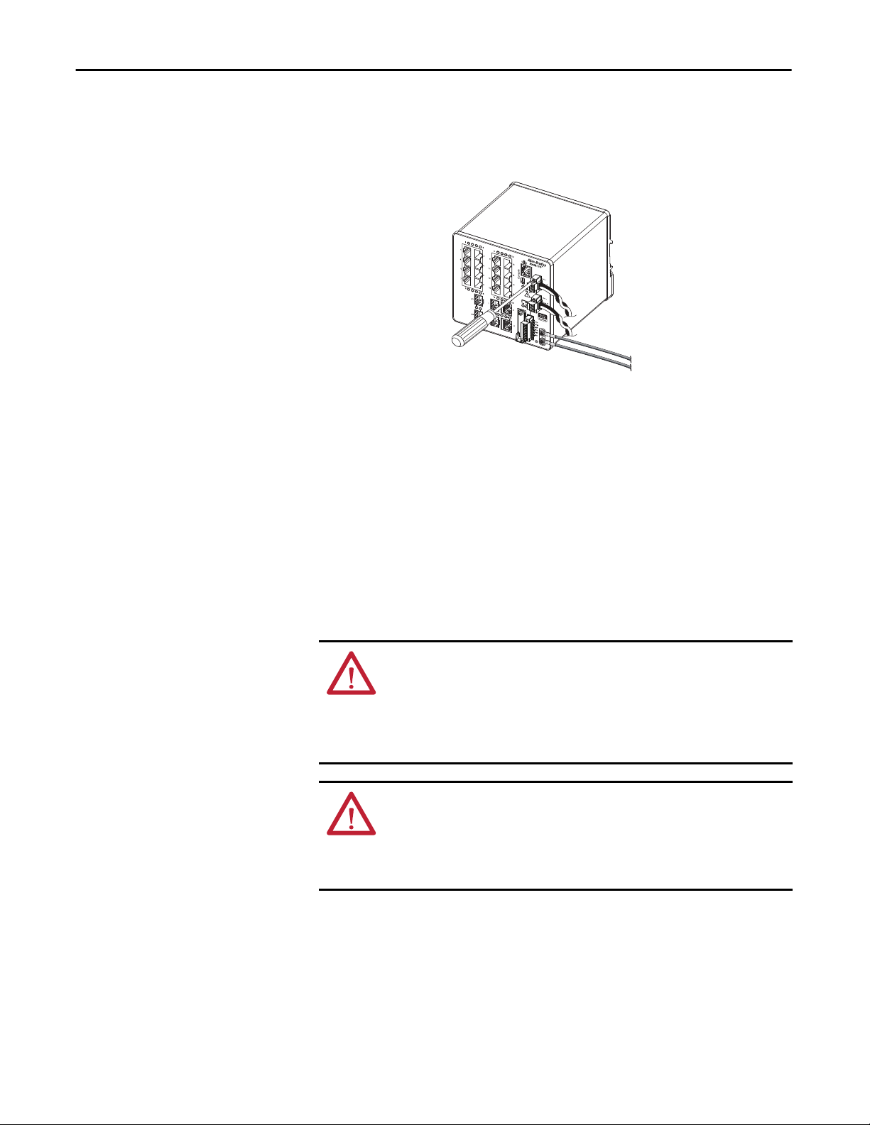
Chapter 2 Switch Installation
2. Use a ratcheting torque flathead screwdriver to tighten the captive screws
on the sides of the power connectors.
32284-M
When you are testing the switch, one power source is sufficient. If you are
installing the switch and are using a second power source, repeat this
procedure for the second power connector (Pwr B), which installs just
below the primary power connector (Pwr A).
3. When you are installing the switch, secure the wires coming from the
power connectors to the rack by using tie wraps.
Wire the Power over Ethernet DC Power Source
This procedure applies only to switches with PoE ports.
WARNING: The console port is intended only for temporary local programming
purposes and not intended for permanent connection. If you connect or
disconnect the console cable with power applied to this module or the
programming device on the other end of the cable, an electrical arc can occur.
This could cause an explosion in hazardous location installations. Be sure that
power is removed or the area is nonhazardous before proceeding.
ATTENTION: To comply with the CE Low Voltage Directive (LVD), this
equipment must be powered from a source compliant with the safety extra low
voltage (SELV) or protected extra low voltage (PELV).
To comply with UL restrictions, this equipment must be powered from a source
compliant with Class 2 or Limited Voltage/Current.
The switch must be wired and grounded.
44 Rockwell Automation Publication 1783-UM004E-EN-P - June 2014
Page 45

Switch Installation Chapter 2
Power supply requirements depend on your application.
Application Power Supply per Port Power Consumption Allen-Bradley Products
PoE only
IEEE 802.3af
PoE and PoE +
IEEE 802.3at Type 2
44…57V DC (48V DC nom) 15.4 W, max Switched mode power supplies:
50…57V DC (54V DC nom) 15.4 W, max for PoE
30 W, max for PoE+
• 1606-XL Standard
• 1606-XLE Essential
• 1606-XLP Compact
• 1606-XLS Performance
WARNING: Before performing any of the following procedures, make sure that
power is removed from the DC circuit or the area is nonhazardous before
proceeding.
2
1. Measure a length of 0.82…0.52 mm
(18…20 AWG) copper wire long
enough to connect to the DC power source.
2. Using an 18-gauge wire-stripping tool, strip each of the two wires to
6.3mm (0.25 in.) ± 0.5 mm (0.02 in.).
Do not strip more than 6.8 mm (0.27 in.) of insulation from the wire.
Stripping more than the recommended amount of wire can leave wire
exposed after installation.
6.3 mm (0.25 in.) ± 0.5 mm (0.02 in.)
31789-M
3. Locate the power connector.
4. Insert the exposed part of the positive wire into the DC+ connection and
the exposed part of the return wire into the DC- connection.
Make sure that you cannot see any wire lead. Only wire with insulation can
extend from the connector.
DC-
DC+
5. Use a ratcheting-torque screwdriver to torque the power connector captive
screws (above the installed wire leads) to 0.23 N•m (2.0 lb•in).
6. Connect the other end of the positive wire (the one connected to DC+) to
the positive terminal on the DC power source, and connect the other end
of the return wire (the one connected to DC-) to the return terminal on
the DC power source.
ATTENTION: If multiple power sources are used, do not exceed the specified
isolation voltage.
Rockwell Automation Publication 1783-UM004E-EN-P - June 2014 45
Page 46

Chapter 2 Switch Installation
Attach the PoE Power Connector
This procedure applies only to switches with PoE ports.
1. Insert the power connector into the DC input terminal block on the
switch front panel.
2. Use a screwdriver to tighten the captive screws on the sides of the power
connector.
PoE Input Pwr
48VDC, 1.2A
ATTENTION: Exposure to some chemicals can degrade the sealing properties of
materials used in the relay. Periodically inspect the relay and check for any
degradation.
Install an SFP Module (optional)
WARNING: When you insert or remove the small form-factor pluggable (SFP)
optical transceiver while power is on, an electrical arc can occur. This could
cause an explosion in hazardous location installations.
Be sure that power is removed or the area is nonhazardous before proceeding.
ATTENTION: Use only Rockwell 1783-SFP100FX, 1783-SFP100LX,
1783-SFP1GSX, or 1783-SFP1GLX SFPs.
ATTENTION: We strongly recommend that you do not install or remove the SFP
module with fiber optic cables attached to it because of the potential damage
to the cables, the cable connector, or the optical interfaces in the SFP module.
Disconnect all cables before removing or installing an SFP module.
IMPORTANT
Installing and removing an SFP module can shorten its useful life. Do not
remove and insert SFP modules more often than is absolutely necessary.
On switch catalog numbers that support communication over fiber optic cable,
SFP modules are inserted into SFP module slots on the front of the switch. These
field-replaceable modules provide the uplink optical interfaces, send (TX) and
receive (RX).
46 Rockwell Automation Publication 1783-UM004E-EN-P - June 2014
Page 47

Switch Installation Chapter 2
You can use any combination of rugged SFP modules. Each SFP module must be
of the same type as the SFP module on the other end of the cable. The cable must
not exceed the stipulated cable length for reliable communications.
When you use commercial SFP modules such as CWDM and 1000BX-U/D,
reduce the maximum operating temperature by 15 °C (59 °F). The minimum
operating temperature is 0 °C (32 °F).
For detailed instructions on installing, removing, and cabling the SFP module,
see your SFP module documentation.
To insert an SFP module into the SFP module slot, follow these steps.
1. Attach an ESD-preventive wrist strap to your wrist and to a grounded bare
metal surface.
2. Grasp both sides of the SFP module and align the module sideways in
front of the slot opening.
ATTENTION: If the SFP module cannot be fully inserted, stop! Do not
force the module into the slot. Rotate the SFP module 180° and try
again.
3. Insert the SFP module into the slot as shown in the following figure until
you feel the connector on the module snap into place in the rear of the slot.
SFP Module
(Bale-type Latch Shown)
32293-M
4. Remove the dust plugs from the SFP module optical ports, store them for
later use.
IMPORTANT
Do not remove the dust plugs from the SFP module port or the rubber
caps from the fiber-optic cable until you are ready to connect the cable.
The plugs and caps protect the SFP module ports and cables from
contamination and ambient light.
Rockwell Automation Publication 1783-UM004E-EN-P - June 2014 47
Page 48

Chapter 2 Switch Installation
Remove SFP Modules from SFP Module Slots
To remove an SFP module from a module receptacle, follow these steps.
1. Attach an ESD-preventive wrist strap to your wrist and to a grounded bare
metal surface.
2. Disconnect the fiber LC connector from the SFP module.
3. Insert a dust plug into the optical ports of the SFP module to keep the
optical interfaces clean.
4. Unlock and remove the SFP module.
If the module has a bale-clasp latch, swing the bale toward you and pull it
gently to eject the module. If the bale-clasp latch is obstructed and you
cannot use your index finger to open it, use a small, flat-blade screwdriver
or other long, narrow instrument to open the bale-clasp latch.
5. Grasp the SFP module between your thumb and index finger, and
carefully remove it from the module slot.
6. Place the removed SFP module in an antistatic bag or other protective
environment.
48 Rockwell Automation Publication 1783-UM004E-EN-P - June 2014
32294-M
Page 49

Switch Installation Chapter 2
Wire the External Alarms
The switch has two alarm input and one Form C (single-pole, double-throw)
alarm output relay circuits for external alarms. The input alarm relay circuits are
designed to sense if the alarm input is open or closed relative to the alarm input
reference pin. The output alarm relay circuit has a single Form C relay, with one
normally open (NO) and one normally closed (NC) contact. You can configure
the output alarm relay as either normally energized or normally de-energized by
using the CLI.
Refer to
Appendix C for an alarm wiring example.
Alarm signals are connected to the switch through the 6-way alarm relay
connector. Three connections are dedicated to the two alarm input circuits:
• Alarm input 1 (IN1)
• Alarm input 2 (IN2)
• Isolated reference ground
An alarm input and the reference ground wiring connection are required to
complete a single input alarm circuit. You must provide either an NO or an NC
dry contact to complete the alarm circuit between reference ground and IN1 or
IN2.
ATTENTION: Do not apply an external voltage source to either the IN1 or IN2
alarm inputs. Limit alarm output wiring to 48 V DC, 0.5 A.
The three remaining connections for the Form C output alarm circuit are as
follows:
• NO output
• NC output
• common
An alarm output and the common wiring connection are required to complete a
single output alarm circuit. The Form C output alarm relay provides one NO and
one NC dry contact.
ATTENTION: Wire connections to the power and relay connector, must be ULand CSA-rated, style 1007 or 1569 twisted-pair copper appliance wiring
material (AWM) wire.
Rockwell Automation Publication 1783-UM004E-EN-P - June 2014 49
Page 50

Chapter 2 Switch Installation
The labels for the alarm relay connector are on the switch panel.
Table 1 - Alarm Relay Connector Labels
Label Connection
NO Alarm Output Normally Open (NO) connection
COM Alarm Output Common connection
NC Alarm Output Normally Closed (NC) connection
IN2 Alarm Input 2
REF Alarm Input Reference Ground connection
IN1 Alarm Input 1
To wire the switch to an external alarm device, follow these steps.
1. Loosen the captive screws that hold the alarm relay connector on the
switch, and remove the connector from the switch chassis.
2. Measure two strands of twisted-pair wire (18…20 AWG) long enough to
connect to the external alarm device.
Choose between setting up an external alarm input or output circuit.
3. Use a wire stripper to remove the casing from both ends of each wire to 6.3
mm (0.25 in.) ± 0.5 mm (0.02 in.).
Do not strip more than 6.8 mm (0.27 in.) of insulation from the wires.
Stripping more than the recommended amount of wire can leave exposed
wire from the alarm relay connector after installation.
4. Insert the exposed wires for the external alarm device into the connections
based on an alarm input or output circuit setup. See
50 Rockwell Automation Publication 1783-UM004E-EN-P - June 2014
32287-M
Table 1 on page 50.
Page 51

Switch Installation Chapter 2
5. Use a ratcheting torque flathead screwdriver to torque the alarm relay
connector captive screw (above the installed wire leads) to 0.23 N•m
(2.0 lb•in).
Do not exceed the recommended torque.
IN1 - External Device Connection 1
REF - External Device Connection 2
32288-M
6. Repeat the above procedure to insert the input and output wires of one
additional external alarm device into the alarm relay connector.
The following figure shows the completed wiring for two external alarm
devices. The first alarm device circuit is wired as an alarm relay input
circuit—the IN1 and REF connections complete the circuit. The second
alarm device circuit is wired as an alarm relay output circuit by using the
normally open side of the form C relay contacts. The NO and COM
connections complete the circuit.
REF—External Device Connection 2
IN1—External Device Connection 1
COM—Wired Connection
NO—Wired Connection
32289-M
Rockwell Automation Publication 1783-UM004E-EN-P - June 2014 51
Page 52

Chapter 2 Switch Installation
Attach the Alarm Relay Connector to the Switch
To attach the alarm relay connector to the front panel of the switch, follow these
steps.
1. Insert the alarm relay connector into the receptacle on the switch front
panel.
2. Use a ratcheting torque flathead screwdriver to tighten the captive screws
on the sides of the alarm relay connector.
Alarm Relay Connector
Upper Captive Screw
32290-M
Connect to 10/100 and 10/100/1000 Ports
The switch 10/100/1000 ports automatically configure themselves to operate at
the speed of attached devices. If the attached ports do not support
autonegotiation, you can explicitly set the speed and duplex parameters.
Connecting devices that do not autonegotiate or that have their speed and duplex
parameters manually set can reduce performance or result in no linkage.
The Auto-MDIX feature is enabled by default. Unless this feature is disabled, you
can use either straight-through or crossover cables to connect to other devices on
the network.
To maximize performance, choose one of these methods for configuring the
Ethernet ports:
• Let the ports autonegotiate both speed and duplex
• Set the port speed and duplex parameters on both ends of the connection
52 Rockwell Automation Publication 1783-UM004E-EN-P - June 2014
Page 53

Switch Installation Chapter 2
Connect to 10BASE-T, 100BASE-TX, or 1000BASE-T Ports
To connect to 10BASE-T, 100BASE-TX, or 1000BASE-T ports, follow these
steps.
ATTENTION: To prevent electrostatic-discharge (ESD) damage, follow
recommended board and component handling procedures.
1. Choose one of these options to connect a device:
• When connecting to workstations, servers, and routers, connect a
straight-through cable to an RJ45 connector on the front panel.
• When connecting to 1000BASE-T-compatible devices, use a twisted
four-pair, Category 5e or higher cable.
10/100 Port
32291-M
10/100/1000 Port
2. Connect the other end of the cable to an RJ45 connector on the other
device.
The Port status indicator turns on when both the switch and the
connected device have an established link.
The Port status indicator is amber while Spanning Tree Protocol (STP)
discovers the topology and searches for loops. This can take up to 30
seconds, and then the Port status indicator turns green.
The following conditions can prevent the Port status indicator from
turning On:
• The device at the other end is not turned On.
• A problem exists with a cable or the adapter installed in the attached
device.
3. Reconfigure and restart the connected device if necessary.
4. Repeat this procedure to connect each device.
Rockwell Automation Publication 1783-UM004E-EN-P - June 2014 53
Page 54

Chapter 2 Switch Installation
Connect to PoE Ports
Switches with PoE ports require a separate power supply. For power supply
requirements based on your application, refer to
1. Insert a straight-through, twisted four-pair, Category 5e or better cable
with an RJ45 connector into the PoE port.
PoE Port
PoE Input Pwr
48VDC, 1.2A
page 44.
2. Insert the other cable end into an RJ45 connector on the other PoE
powered device.
54 Rockwell Automation Publication 1783-UM004E-EN-P - June 2014
Page 55

Switch Installation Chapter 2
Connect to SFP Modules
To connect a fiber-optic cable to an SFP module, follow these steps.
ATTENTION: Do not remove the rubber plugs from the SFP module port or the
rubber caps from the fiber-optic cable until you are ready to connect the cable.
The plugs and caps protect the SFP module ports and cables from
contamination and ambient light.
1. Remove the rubber plugs from the module port and fiber-optic cable, and
store them for future use.
2. Insert one end of the fiber-optic cable into the SFP module port.
LC Connector
3. Insert the other cable end into a fiber-optic receptacle on a target device.
4. Observe the port status indicator:
• The status indicator turns amber while the SFP discovers the network
topology and searches for loops. This process takes about 30 seconds,
and then the port status indicator turns green.
• The status indicator turns green when the switch and the target device
have an established link.
• The status indicator turns off if the target device is not turned on or
there is a problem with the cable or the adapter installed in the target
device.
If necessary, reconfigure and restart the switch or the target device.
Rockwell Automation Publication 1783-UM004E-EN-P - June 2014 55
Page 56

Chapter 2 Switch Installation
Connect to a Dual-purpose Port
A dual-purpose port is a single port with two interfaces, one for an RJ45 cable
and another for an approved SFP module. Only one interface can be active at a
time. If both interfaces are connected, the SFP module has priority.
ATTENTION: Do not remove the rubber plugs from the SFP module port or the
rubber caps from the fiber-optic cable until you are ready to connect the cable.
The plugs and caps protect the SFP module ports and cables from
contamination and ambient light.
To connect to a dual-purpose port, follow these steps.
1. Connect an RJ45 connector to the 10/100/1000 port, or install an SFP
module into the SFP module slot, and connect a cable to the SFP module
port.
LC Connector
RJ45 Connector
32296-M
2. Connect the other end of the cable to the other device.
By default, the switch detects whether an RJ45 connector or SFP module
is connected to a dual-purpose port and configures the port accordingly.
You can change this setting and configure the port to recognize only an
RJ45 connector or only an SFP module by using the media type interface
configuration command. For more information, refer to the appropriate
documentation at
http://www.Cisco.com.
56 Rockwell Automation Publication 1783-UM004E-EN-P - June 2014
Page 57

Switch Installation Chapter 2
ArmorStratix 5700 Switch Installation
ATTENTION: Environment and Enclosure
This equipment is intended for use in overvoltage Category II applications (as
defined in IEC 60664-1), at altitudes up to 2000 m (6562 ft) without derating.
This equipment is not intended for use in residential environments and may not
provide adequate protection to radio communication services in such
environments.
This equipment is supplied as enclosed equipment. It should not require additional
system enclosure when used in locations consistent with the enclosure type ratings
stated in the Specifications section of this publication. Subsequent sections of this
publication may contain additional information regarding specific enclosure type
ratings, beyond what this product provides, that are required to comply with
certain product safety certifications.
In addition to this publication, see the following:
• Industrial Automation Wiring and Grounding Guidelines, publication
for additional installation requirements
• NEMA Standard 250 and IEC 60529, as applicable, for explanations of the
degrees of protection provided by enclosures
Installation Guidelines
1770-4.1,
ATTENTION: Prevent Electrostatic Discharge
This equipment is sensitive to electrostatic discharge, which can cause internal
damage and affect normal operation. Follow these guidelines when you handle
this equipment:
• Do not touch connectors or pins on component boards.
• Do not touch circuit components inside the equipment.
ATTENTION: Make sure all connectors and caps are securely tightened to
properly seal the connections against leaks and maintain IP enclosure type
requirements.
ATTENTION: The console ports are intended for temporary local programming
purposes only and not intended for permanent connection.
The console port cables are not to exceed 3.0 m (9.84 ft) and must not contain
hubs.
Rockwell Automation Publication 1783-UM004E-EN-P - June 2014 57
Page 58

Chapter 2 Switch Installation
When determining where to place the switch, observe these guidelines:
• Airflow around the switch is unrestricted. To prevent the switch from
overheating, observe the following minimum clearances:
– Top and bottom: 50.8 mm (2.0 in.)
– Sides: 50.8 mm (2.0 in.)
– Front: 50.8 mm (2.0 in.)
• For 10/100 ports and 10/100/1000 ports, the cable length from a switch
to an attached device cannot exceed 100 m (328 ft).
• The copper cable length from a switch to an attached device cannot exceed
the distance specified in
Appendix C.
• For maximum noise immunity, X-code shielded cables must be used on
M12 uplink ports. For recommended M12 media, refer to
http://
ab.rockwellautomation.com/Connection-Devices/EtherNet-Media.
• Temperature surrounding the unit does not exceed 60 °C (140 °F).
• Clearance to front and rear panels meets these conditions:
– Front-panel status indicators can be easily read.
– Access to ports is sufficient for unrestricted cabling.
– Front-panel direct current (DC) power connectors and the alarm relay
connector are within reach of the connection to the DC power source.
• Cabling is away from sources of electrical noise, such as radios, power lines,
and fluorescent lighting fixtures.
• Connect the unit to only an IP67-rated power supply. Rockwell
Automation offers a Bulletin 1607 IP67-rated power supply to provide
24V DC power to the switch.
ATTENTION: Do not wire more than 1 conductor on any single terminal.
58 Rockwell Automation Publication 1783-UM004E-EN-P - June 2014
Page 59

Switch Installation Chapter 2
Install or Remove the SD Card (optional)
The switch supports a Secure Digital (SD) memory card to store firmware and
the startup configuration. This storage makes it possible to replace a switch
without reconfiguring the replacement switch.
The SD memory card cover protects the card against shock and vibration by
holding the card in place. The cover is hinged and secured with captive screws.
The slot for the SD memory card is located on the side of the switch.
To install or replace the SD card, follow these steps.
1. On the side of the switch, loosen the captive screws until they are free.
380394
2. Install or remove the card:
• To install the card, slide it into the slot, and press on it until it clicks in
place. The card is keyed so that you cannot insert it the wrong way.
• To remove the card, push it in until it releases for it to pop out. Place it
in an antistatic bag to protect it from static discharge.
3. Close the guard door and fasten the captive screws to 1.8…2.2N•m
(15.93…19.47 lb •in) to maintain IP67 compliance.
Rockwell Automation Publication 1783-UM004E-EN-P - June 2014 59
Page 60

Chapter 2 Switch Installation
Verify Switch Operation
Before installing the switch in its final location, power on the switch, and verify
that the switch powers up.
The time required for the switch to start up is directly related to your switch
configuration. Start time is negatively affected by such things as the following:
• Spanning Tree Learning mode
• Number of files or images in onboard flash memory
To test the switch, follow these steps.
1. Power on the switch.
To apply power to a switch that is directly connected to a DC power
source, locate the circuit breaker on the panel board that services the DC
circuit, and switch the circuit breaker to the ON position.
2. Verify the start-up sequence.
When you power on the switch, it automatically begins a start-up fast
routine. The System status indicator blinks green as the IOS software
image loads. If the routine fails, the System status indicator turns red.
IMPORTANT
Start-up failures are usually fatal to the switch. Contact your Rockwell
Automation representative immediately if your switch does not
complete the start sequence successfully.
IMPORTANT
You can disable boot fast and run the Power-on Self Test (POST) by
using the IOS CLI. See the appropriate documentation at
http://www.Cisco.com for more information.
3. After successfully running this test, do the following:
a. Turn off power to the switch.
b. Disconnect the cables.
c. Decide where you want to install the switch
60 Rockwell Automation Publication 1783-UM004E-EN-P - June 2014
Page 61

Switch Installation Chapter 2
Mount the Switch
ATTENTION: To prevent bodily injury when mounting or servicing this unit in a
rack, you must take special precautions to ensure that the system remains
stable. The following guidelines are provided to ensure your safety:
• This unit should be mounted at the bottom of the rack if it is the only unit in the
rack.
• When mounting this unit in a partially filled rack, load the rack from the
bottom to the top with the heaviest component at the bottom of the rack.
• If the rack is provided with stabilizing devices, install the stabilizers before
mounting or servicing the unit in the rack.
To mount the switch, follow these steps.
1. Position the rear panel of the switch against the wall or a panel in the
desired location.
2. Place a number-10 screw that you provide through each mounting ear, and
screw them into the wall.
32477
Rockwell Automation Publication 1783-UM004E-EN-P - June 2014 61
Page 62

Chapter 2 Switch Installation
Ground the Switch
ATTENTION: This equipment must be grounded. Never defeat the ground
conductor or operate the equipment in the absence of a suitably installed
ground conductor. Contact the appropriate electrical inspection authority or an
electrician if you are uncertain that suitable grounding is available.
This equipment is intended to be grounded to comply with emission and immunity
requirements. Make sure that the switch functional ground lug is connected to
earth ground during normal use.
ATTENTION: To make sure that the equipment is reliably connected to earth
ground, follow the grounding procedure instructions and use a suitable ring
terminal lug, such as Thomas & Bett part number 10RCR or equivalent.
Use at least 4 mm2 (12 AWG) wire to connect to the external grounding screw.
The ground lug is not supplied with the switch. You can use one of the these
options:
• Single ring terminal
• Two single ring terminals
To ground the switch to earth ground, follow these steps. Be sure to follow any
grounding requirements at your site.
1. Use a Phillips screwdriver or a ratcheting torque screwdriver with a Phillips
head to remove the ground screw from the front panel of the switch.
Store the ground screw for later use.
2. Use the manufacturer’s guidelines to determine the wire length to be
stripped.
3. Insert the ground wire into the ring terminal lug and use a crimping tool to
crimp the terminal to the wire.
If you are using two ring terminals, repeat this action for the second ring
terminal.
32273-M
4. Slide the ground screw through the terminal.
62 Rockwell Automation Publication 1783-UM004E-EN-P - June 2014
Page 63

Switch Installation Chapter 2
5. Insert the ground screw into the functional ground screw opening on the
front panel.
32498
6. Use a ratcheting torque screwdriver to tighten the ground screws and ring
terminal lugs to the switch front panel to 0.4 N
m (3.5 lbin).
Do not exceed the recommended torque.
7. Attach the other end of the ground wire to a grounded bare metal surface,
such as a ground bus, a grounded DIN rail, or a grounded bare rack.
Rockwell Automation Publication 1783-UM004E-EN-P - June 2014 63
Page 64

Chapter 2 Switch Installation
Connect the Switch to a DC Power Source
You must supply a power solution for the device. An IP67-rated cordset or
patchcord with a female-end, 4-pin mini connector is required to provide power
to the switch. Rockwell Automation offers a Bulletin 1607 IP67-rated power
supply to provide 24V DC power to the switch. Ethernet communication and
control power cables are available separately.
Power over Ethernet
For switches with Power over Ethernet (PoE) capability, PoE power is drawn
from the single power connection. There is no separate power input for PoE.
Switch Configuration Required Power Input Power Supplied per Port
PoE 44-57V 15.4 W, max
PoE+ 50-57V 30 W, max
Non-PoE 9.6…60V Not applicable
Power Cables and Cordsets
Cordsets
32475
No. of Pins Assembly Rating Straight Male Right Angle Male
4 600V, 10 A 889N-M4AFC
(1) Replace (1) with 6 (6 ft), 12 (12 ft), or 20 (20 ft) for standard cable lengths.
(1)
F
889N-E4AFC
(1)
Patchcords
32476
No. of
Pins
4 600V, 10 A 889N-F4AFNM-
(1) Replace (1) with 1 (1 m), 2 (2 m), 5 (5 m), and 10 (10 m) for standard cable lengths.
Assembly
Rating
Straight Female,
Straight Male
(1)
Straight Female,
Right Angle Male
889N-F4AFNE-
(1)
Right Angle
Female, Straight
Male
889N-R4AFNM-
(1)
Right Angle
Female,
Right Angle Male
889N-R4AFNE-
Connect the DC power to the switch through the front panel connector.
F
(1)
64 Rockwell Automation Publication 1783-UM004E-EN-P - June 2014
32478
Page 65

Switch Installation Chapter 2
Wire External Alarms
Some switch models have the following for external alarms:
• One input alarm relay circuit to sense whether the alarm input is open or
closed relative to the alarm input reference pin.
• One output alarm relay circuit with a single Form C (single-pole,
double-throw) relay with one normally open (NO) and one normally
closed (NC) contact. You can configure the output alarm as either
normally energized or normally de-energized by using the CLI.
Refer to
Appendix C for an alarm wiring example.
Alarm signals are connected to the switch through the 6-way alarm relay
connector. Three connections are dedicated to the alarm input.
An alarm input and the reference ground wiring connection are required to
complete a single input alarm circuit. You must provide either an NO or an NC
dry contact to complete the alarm circuit between reference ground and the
alarm input.
The three remaining connections for the Form C output alarm circuit are as
follows:
• NO output
• NC output
• common
An alarm output and the common wiring connection are required to complete a
single output alarm circuit. The Form C output alarm relay provides one NO and
one NC dry contact.
Use M12 A-coded cable to connect to the alarm connector on the switch.
Recommended torque is 0.5…0.8 N•m (4.43… 7.08 lb•in. The recommended
cable part number from Molex is 1200650523. One end of the cable has M12 Acoded connector and the other end is open.
The labels for the alarm relay connector are on the switch panel.
Table 2 - Alarm Relay Connector Labels
Label Connection
NO Alarm Output Normally Open (NO) connection
COM Alarm Output Common connection
NC Alarm Output Normally Closed (NC) connection
REF Alarm Input Reference Ground connection
IN1 Alarm Input 1
Rockwell Automation Publication 1783-UM004E-EN-P - June 2014 65
Page 66

Chapter 2 Switch Installation
ATTENTION: The input voltage source of the alarm output relay circuit must be
an isolated source and limited to less than or equal to 24 VDC, 1.0 A or 48 VDC,
0.5 A.
Connect to 10/100 and 10/100/1000 Ports
The switch 10/100 and 10/100/1000 ports automatically configure themselves
to operate at the speed of attached devices. If the attached ports do not support
autonegotiation, you can explicitly set the speed and duplex parameters.
Connecting devices that do not autonegotiate or that have their speed and duplex
parameters manually set can reduce performance or result in no linkage.
The Auto-MDIX feature is enabled by default. Unless this feature is disabled, you
can use either straight-through or crossover cables to connect to other devices on
the network.
To maximize performance, choose one of these methods for configuring the
Ethernet ports:
• Let the ports autonegotiate both speed and duplex
• Set the port speed and duplex parameters on both ends of the connection
Connect to PoE Ports
For power supply requirements based on your application, refer to page 64.
1. Insert a straight-through, twisted four-pair, Category 5e or better cable
with an M12 connector into the PoE port.
32497
2. Insert the other cable end into an M12 connector on the other PoE
powered device.
66 Rockwell Automation Publication 1783-UM004E-EN-P - June 2014
Page 67

Switch Installation Chapter 2
Set Up the Switch Initially with Express Setup
When you first set up the switch, use Express Setup to enter the initial IP address.
Doing this enables the switch to be used as a managed switch. You can then access
the switch through the IP address for additional configuration.
IMPORTANT
You need this equipment to set up the switch:
• A computer with Windows 2000, Windows XP, Windows 2003, or
Windows Vista operating system installed
• A supported web browser (Internet Explorer 9.0, 10.0, and 11.0, or
Firefox 25, 26) with JavaScript enabled
• A straight-through or crossover Category 5 Ethernet cable to connect a
computer to the switch
or
For ArmorStratix 5700 switches, an M12-to-RJ45 patchcord, such as
Allen-Bradley catalog number 1585D-M4TBJM-2, to connect a computer
to the switch
Do not run Express Setup with an SD card inserted in the switch.
• For 1783-BMS4S2SGL or 1783-BMS4S2SGA switches:
– A Gigabit copper SFP module, such as Cisco model number GLC-T
or
– A Gigabit fiber-to-Ethernet media converter
Do the following to configure your computer:
• Disable any wireless interface running on your personal computer.
• Disable other networks in your system.
• Set your computer to automatically determine its IP address (DHCP)
versus statically configured.
• Disable any static DNS servers.
• Disable browser proxy settings.
Typically, browser settings are in Tools > Internet Options > Connections >
LAN Settings.
Rockwell Automation Publication 1783-UM004E-EN-P - June 2014 67
Page 68

Chapter 2 Switch Installation
To run Express Setup, follow these steps.
1. Make sure that at least one switch Ethernet port is available for Express
Setup.
IMPORTANT
For 1783-BMS4S2SGL or 1783-BMS4S2SGA switches, you must use
port Gi1/1 for Express Setup. Do not use the console port.
During Express Setup, the switch acts as a DHCP server. If your personal
computer has a static IP address, change your personal computer settings
before you begin to temporarily use DHCP.
2. Apply power to the switch.
When the switch powers on, it begins its power on sequence. The power
on sequence takes approximately 60 seconds to complete.
3. Make sure that the power on sequence has completed by verifying that the
EIP Mod and Setup status indicators are flashing green.
If the switch fails the power on sequence, the EIP Mod status indicator
turns red.
68 Rockwell Automation Publication 1783-UM004E-EN-P - June 2014
Page 69

Switch Installation Chapter 2
4. Press and release the Express Setup button. Wait for a few seconds until the
status indicator on one of the unconnected switch ports flashes green.
This button is recessed 16 mm (0.63 in.) behind the panel. Use a small
tool, such as a paper clip, to reach the button.
Stratix 5700
Express Setup Button
ArmorStratix 5700
Express Setup Button
Rockwell Automation Publication 1783-UM004E-EN-P - June 2014 69
Page 70

Chapter 2 Switch Installation
5. Connect a Category 5 Ethernet cable (not provided) from the flashing
switch port to the Ethernet port on a computer.
If you wait too long to connect the cable, the Setup status indicator turns
off.
or
For 1783-BMS4S2SGL or 1783-BMS4S2SGA switches, do one of the
following:
• Insert a copper SFP module into port Gi1/1, and then connect a
Category 5 Ethernet cable from the SFP module to the Ethernet port
on a computer.
• Use a fiber-to-Ethernet media converter to connect port Gi1/1 to the
Ethernet port on a computer.
IMPORTANT
Port Gi1/1 does not flash during setup, but must be used to connect
1783-BMS4S2SGL or 1783-BMS4S2SGA switches to a computer.
6. Start an Internet browser session on the computer and navigate to
http://169.254.0.1.
If you have a home page configured, the switch configuration loads instead
of your normal home page.
The switch prompts you for the default switch user name and password.
7. Leave the user name blank and enter the default switch password: switch.
IMPORTANT
In some scenarios, the switch requires you to enter the switch
password multiple times before it accepts the password.
8. If the Express Setup window does not appear, do the following:
• Enter the URL of a well-known website in your browser to be sure the
browser is working correctly. Your browser then automatically redirects
to the Express Setup web page.
• Verify that any proxy settings or pop-up blockers are disabled on your
browser.
• Verify that any wireless interface is disabled on the computer.
70 Rockwell Automation Publication 1783-UM004E-EN-P - June 2014
Page 71

Switch Installation Chapter 2
9. Complete the fields.
To view fields for Common Industrial Protocol (CIP), you must click
Advanced Settings.
Rockwell Automation Publication 1783-UM004E-EN-P - June 2014 71
Page 72

Chapter 2 Switch Installation
Field Description
Network Settings
Host Name The name of the device.
Management Interface (VLAN ID) The name and ID of the management VLAN through which the switch is managed. Choose an existing VLAN to be the
IP Assignment Mode The IP Assignment mode determines whether the switch IP information is manually assigned (static) or is automatically
IP Address The IP address and associated subnet mask are unique identifiers for the switch in a network:
Default Gateway (optional) The IP address for the default gateway. A gateway is a router or a dedicated network device that enables the switch to
NTP Server The IP address of the Network Time Protocol (NTP) server. NTP is a networking protocol for clock synchronization between
User Enter the user name.
Password, Confirm Password The password for the switch can have up to 63 alphanumeric characters, can start with a number, is case-sensitive, and can have
CIP VLAN The VLAN on which Common Industrial Protocol (CIP) is enabled. The CIP VLAN can be the same as the management VLAN or
IP Address The IP address and subnet mask for the CPI VLAN if the CIP VLAN is different from the management VLAN. The format is a 32-bit
Same As Management VLAN Indicates whether the settings for the CIP VLAN are the same as the management VLAN.
Telnet, CIP and Enable Password (optional),
Confirm Password
Same As Admin Password Sets the password used for Telnet and CIP security to the same user password specified under Network Settings.
management VLAN.
The default ID is 1. The default name for the management VLAN is default. The number can be from 1…1001. Be sure that the
switch and your network management station are in the same VLAN. Otherwise, you lose management connectivity to the
switch.
The management VLAN is the broadcast domain through which management traffic is sent between specific users or devices. It
provides broadcast control and security for management traffic that must be limited to a specific group of users, such as the
administrators of your network. It also provides secure administrative access to all devices in the network at all times.
assigned by a Dynamic Host Configuration Protocol (DHCP) server. The default is Static.
We recommend that you click Static and manually assign the IP address for the switch. You can then use the same IP address
whenever you want to access the Device Manager Web interface.
If you click DHCP, the DHCP ser ver automatically assigns an IP address, subnet mask, and default gateway to the switch. As long
as the switch is not restarted, the switch continues to use the assigned IP information, and you are able to use the same IP
address to access the Device Manager Web interface.
If you manually assign the switch IP address and your network uses a DHCP server, be sure that the IP address that you give to
the switch is not within the range of addresses that the DHCP server automatically assigns to other devices. This prevents IP
address conflicts between the switch and another device.
• The IP address format is a 32-bit numeric address written as four numbers separated by periods. Each number can be from
0…255.
• The subnet mask is the network address that identifies the subnetwork (subnet) to which the switch belongs. Subnets are
used to segment the devices in a network into smaller groups. The default is 255.255.255.0.
This field is enabled only if the IP Assignment mode is Static.
Make sure that the IP address that you assign to the switch is not being used by another device in your network. The IP address
and the default gateway cannot be the same.
communicate with devices in other networks or subnetworks. The default gateway IP address must be part of the same subnet
as the switch IP address. The switch IP address and the default gateway IP address cannot be the same.
If all of your devices are in the same network and a default gateway is not used, you do not need to enter an IP address in this
field. This field is enabled only if the IP assignment mode is Static.
You must specify a default gateway if your network management station and the switch are in different networks or
subnetworks. Otherwise, the switch and your network management station cannot communicate with each other.
computer systems over packet-switched, variable-latency data networks.
embedded spaces. The password cannot be a single digit, it cannot contain a ? or a tab, and it does not allow spaces at the
beginning or the end. The default is switch.
To complete initial setup, you must change the password from the default password, switch.
This password is also used as the Control Industrial Protocol (CIP) security password. We recommend that you provide a
password to the switch to secure access to the device manager.
Advanced Settings
you can isolate CIP traffic on another VLAN that is already configured on this device.
numeric address written as four numbers separated by periods. Each number can be from 0…255.
Make sure that the IP address that you assign to this device is not being used by another device in your network.
The password used for Telnet and CIP security.
72 Rockwell Automation Publication 1783-UM004E-EN-P - June 2014
Page 73

Switch Installation Chapter 2
10. Click Submit.
The switch initializes its configuration for typical industrial EtherNet/IP
applications. The switch then redirects you to the logon page for the
Device Manager Web interface. You can continue to launch the Device
Manager Web interface for further configuration or exit the application.
11. Turn off DC power at the source, disconnect all cables to the switch, and
install the switch in your network.
IMPORTANT
For 1783-BMS4S2SGL or 1783-BMS4S2SGA switches, make sure
DC power is disconnected prior to disconnecting Ethernet cables.
12. After you complete Express Setup, refresh the computer IP address:
• For a dynamically-assigned IP address, disconnect the computer from
the switch and reconnect the computer to the network. The network
DHCP server assigns a new IP address to the computer.
• For a statically-assigned IP address, change it to the previously
configured IP address.
Rockwell Automation Publication 1783-UM004E-EN-P - June 2014 73
Page 74

Chapter 2 Switch Installation
Notes:
74 Rockwell Automation Publication 1783-UM004E-EN-P - June 2014
Page 75

Switch Software Features
Topic Page
Port Numbering 76
Global Macro 82
Smartports 83
Power over Ethernet (PoE) 85
VLANs 90
IGMP Snooping with Querier 93
Spanning Tree Protocol 94
Port Thresholds 95
Port Security 97
EtherChannels 98
DHCP Persistence 100
CIP Sync Time Synchronization (Precision Time Protocol) 100
Network Address Translation (NAT) 101
Resilient Ethernet Protocol 107
SNMP 111
Port Mirroring 113
Routing 113
SD Card Synchronization 114
Alarms 114
Cryptographic IOS Software (optional) 114
Advanced Software Features 115
Chapter 3
Rockwell Automation Publication 1783-UM004E-EN-P - June 2014 75
Page 76

Chapter 3 Switch Software Features
Port Numbering
The port ID consists of port type (Gigabit Ethernet for Gigabit ports and Fast
Ethernet for 10/100 Mbps ports), unit number (always 1), and port number (1-2
for Gigabit ports, 1-18 for all others, depending on catalog numbers). Gigabit
Ethernet is abbreviated as Gi and Fast Ethernet as Fa.
The following table shows port numbering for the switch.
Table 3 - Port Numbering
Cat. No. Description Port Numbering on Switch Labels Port Numbering in config.text File
1783-BMS06SL 6-port (4 Ethernet ports; 2 SFP slots) managed switch; lite
firmware
1783-BMS06SA 6-port (4 Ethernet ports; 2 SFP slots) managed switch; full
firmware
1783-BMS06TL 6-port (6 Ethernet ports) managed switch; lite firmware 1
1783-BMS06TA 6-port (6 Ethernet ports) managed switch; full firmware 1
1783-BMS06SGL 6-port (4 Ethernet ports; 2 SFP Gigabit slots) managed switch; lite
firmware
1783-BM06SGA 6-por t (4 Ethernet ports; 2 SFP Gigabit slots) managed switch; full
firmware
1783-BMS06TGL 6-port (4 Ethernet ports; 2 Gigabit ports) managed switch; full
firmware
1
2
3
4
5
6
1
2
3
4
5
6
2
3
4
5
6
2
3
4
5
6
1
2
3
4
1
2
1
2
3
4
1
2
1
2
3
4
1
2
Fa1/1
Fa1/2
Fa1/3
Fa1/4
Fa1/5
Fa1/6
Fa1/1
Fa1/2
Fa1/3
Fa1/4
Fa1/5
Fa1/6
Fa1/1
Fa1/2
Fa1/3
Fa1/4
Fa1/5
Fa1/6
Fa1/1
Fa1/2
Fa1/3
Fa1/4
Fa1/5
Fa1/6
Fa1/1
Fa1/2
Fa1/3
Fa1/4
Gi1/1
Gi1/2
Fa1/1
Fa1/2
Fa1/3
Fa1/4
Gi1/1
Gi1/2
Fa1/1
Fa1/2
Fa1/3
Fa1/4
Gi1/1
Gi1/2
76 Rockwell Automation Publication 1783-UM004E-EN-P - June 2014
Page 77

Switch Software Features Chapter 3
Table 3 - Port Numbering (continued)
Cat. No. Description Port Numbering on Switch Labels Port Numbering in config.text File
1783-BMS06TGA 6-port (4 Ethernet ports; 2 Gigabit ports) managed switch; full
firmware
1783-BMS10CL 10-port (8 Ethernet ports; 2 combo ports) managed switch; lite
firmware
1783-BMS10CA 10-port (8 Ethernet ports; 2 combo ports) managed switch; full
firmware
1783-BMS10CGL 10-por t (8 Ethernet ports; 2 combo Gigabit ports) managed
switch; lite firmware
1783-BMS10CGA 10-port (8 Ethernet ports; 2 combo Gigabit ports) managed
switch; full firmware
1
2
3
4
1
2
1
2
3
4
5
6
7
8
9
10
1
2
3
4
5
6
7
8
9
10
1
2
3
4
5
6
7
8
1
2
1
2
3
4
5
6
7
8
1
2
Fa1/1
Fa1/2
Fa1/3
Fa1/4
Gi1/1
Gi1/2
Fa1/1
Fa1/2
Fa1/3
Fa1/4
Fa1/5
Fa1/6
Fa1/7
Fa1/8
Fa1/9
Fa1/10
Fa1/1
Fa1/2
Fa1/3
Fa1/4
Fa1/5
Fa1/6
Fa1/7
Fa1/8
Fa1/9
Fa1/10
Fa1/1
Fa1/2
Fa1/3
Fa1/4
Fa1/5
Fa1/6
Fa1/7
Fa1/8
Gi1/1
Gi1/2
Fa1/1
Fa1/2
Fa1/3
Fa1/4
Fa1/5
Fa1/6
Fa1/7
Fa1/8
Gi1/1
Gi1/2
Rockwell Automation Publication 1783-UM004E-EN-P - June 2014 77
Page 78

Chapter 3 Switch Software Features
Table 3 - Port Numbering (continued)
Cat. No. Description Port Numbering on Switch Labels Port Numbering in config.text File
1783-BMS10CGN 10-port (8 Ethernet ports; 2 combo Gigabit ports) managed
switch; full firmware; NAT
1783-BMS10CGP 10-port (8 Ethernet ports; 2 combo Gigabit ports) managed
switch; full firmware; PTP
1783-BMS12T4E2CGNK 18-port (12 Ethernet ports; 4 PoE/PoE+ ports; 2 combo Gigabit
ports) managed switch; full firmware; NAT; conformal coating
1
2
3
4
5
6
7
8
1
2
1
2
3
4
5
6
7
8
1
2
1
2
3
4
5
6
7
8
9
10
11
12
13
14
15
16
1
2
Fa1/1
Fa1/2
Fa1/3
Fa1/4
Fa1/5
Fa1/6
Fa1/7
Fa1/8
Gi1/1
Gi1/2
Fa1/1
Fa1/2
Fa1/3
Fa1/4
Fa1/5
Fa1/6
Fa1/7
Fa1/8
Gi1/1
Gi1/2
Fa1/1
Fa1/2
Fa1/3
Fa1/4
Fa1/5
Fa1/6
Fa1/7
Fa1/8
Fa1/9
Fa1/10
Fa1/11
Fa1/12
Fa1/13
Fa1/14
Fa1/15
Fa1/16
Gi1/1
Gi1/2
78 Rockwell Automation Publication 1783-UM004E-EN-P - June 2014
Page 79

Switch Software Features Chapter 3
Table 3 - Port Numbering (continued)
Cat. No. Description Port Numbering on Switch Labels Port Numbering in config.text File
1783-BMS12T4E2CGP 18-port (12 Ethernet ports; 4 PoE/PoE+ ports; 2 combo Gigabit
ports) managed switch; full firmware
1783-BMS12T4E2CGL 18-port (12 Ethernet ports; 4 PoE/PoE+ ports; 2 combo Gigabit
ports) managed switch; lite firmware
1783-BMS20CL 20-port (16 Ethernet ports; 2 SFP slots; 2 combo ports) managed
switch; lite firmware
1
2
3
4
5
6
7
8
9
10
11
12
13
14
15
16
1
2
1
2
3
4
5
6
7
8
9
10
11
12
13
14
15
16
1
2
1
2
3
4
5
6
7
8
9
10
11
12
13
14
15
16
17
18
19
20
Fa1/1
Fa1/2
Fa1/3
Fa1/4
Fa1/5
Fa1/6
Fa1/7
Fa1/8
Fa1/9
Fa1/10
Fa1/11
Fa1/12
Fa1/13
Fa1/14
Fa1/15
Fa1/16
Gi1/1
Gi1/2
Fa1/1
Fa1/2
Fa1/3
Fa1/4
Fa1/5
Fa1/6
Fa1/7
Fa1/8
Fa1/9
Fa1/10
Fa1/11
Fa1/12
Fa1/13
Fa1/14
Fa1/15
Fa1/16
Gi1/1
Gi1/2
Fa1/1
Fa1/2
Fa1/3
Fa1/4
Fa1/5
Fa1/6
Fa1/7
Fa1/8
Fa1/9
Fa1/10
Fa1/11
Fa1/12
Fa1/13
Fa1/14
Fa1/15
Fa1/16
Fa1/17
Fa1/18
Fa1/19
Fa1/20
Rockwell Automation Publication 1783-UM004E-EN-P - June 2014 79
Page 80

Chapter 3 Switch Software Features
Table 3 - Port Numbering (continued)
Cat. No. Description Port Numbering on Switch Labels Port Numbering in config.text File
1783-BMS20CA 20-port (16 Ethernet ports; 2 SFP slots; 2 combo ports) managed
switch; full firmware
1783-BMS20CGL 20-por t (16 Ethernet ports; 2 SFP slots; 2 combo Gigabit ports)
managed switch; lite firmware
1
2
3
4
5
6
7
8
9
10
11
12
13
14
15
16
17
18
19
20
1
2
3
4
5
6
7
8
9
10
11
12
13
14
15
16
17
18
1
2
Fa1/1
Fa1/2
Fa1/3
Fa1/4
Fa1/5
Fa1/6
Fa1/7
Fa1/8
Fa1/9
Fa1/10
Fa1/11
Fa1/12
Fa1/13
Fa1/14
Fa1/15
Fa1/16
Fa1/17
Fa1/18
Fa1/19
Fa1/20
Fa1/1
Fa1/2
Fa1/3
Fa1/4
Fa1/5
Fa1/6
Fa1/7
Fa1/8
Fa1/9
Fa1/10
Fa1/11
Fa1/12
Fa1/13
Fa1/14
Fa1/15
Fa1/16
Fa1/17
Fa1/18
Gi1/1
Gi1/2
80 Rockwell Automation Publication 1783-UM004E-EN-P - June 2014
Page 81

Switch Software Features Chapter 3
Table 3 - Port Numbering (continued)
Cat. No. Description Port Numbering on Switch Labels Port Numbering in config.text File
1783-BMS20CGN 20-port (16 Ethernet ports; 2 SFP slots; 2 combo Gigabit ports)
managed switch; full firmware; NAT
1783-BMS20CGP 20-port (16 Ethernet ports; 2 SFP slots; 2 combo Gigabit ports)
managed switch; full firmware; PTP
1
2
3
4
5
6
7
8
9
10
11
12
13
14
15
16
17
18
1
2
1
2
3
4
5
6
7
8
9
10
11
12
13
14
15
16
17
18
1
2
Fa1/1
Fa1/2
Fa1/3
Fa1/4
Fa1/5
Fa1/6
Fa1/7
Fa1/8
Fa1/9
Fa1/10
Fa1/11
Fa1/12
Fa1/13
Fa1/14
Fa1/15
Fa1/16
Fa1/17
Fa1/18
Gi1/1
Gi1/2
Fa1/1
Fa1/2
Fa1/3
Fa1/4
Fa1/5
Fa1/6
Fa1/7
Fa1/8
Fa1/9
Fa1/10
Fa1/11
Fa1/12
Fa1/13
Fa1/14
Fa1/15
Fa1/16
Fa1/17
Fa1/18
Gi1/1
Gi1/2
Rockwell Automation Publication 1783-UM004E-EN-P - June 2014 81
Page 82

Chapter 3 Switch Software Features
Table 3 - Port Numbering (continued)
Cat. No. Description Port Numbering on Switch Labels Port Numbering in config.text File
1783-BMS20CGPK 20-port (16 Ethernet ports; 2 SFP slots; 2 combo Gigabit ports)
managed switch; full firmware; PTP; conformal coating
1
2
3
4
5
6
7
8
9
10
11
12
13
14
15
16
17
18
1
2
Fa1/1
Fa1/2
Fa1/3
Fa1/4
Fa1/5
Fa1/6
Fa1/7
Fa1/8
Fa1/9
Fa1/10
Fa1/11
Fa1/12
Fa1/13
Fa1/14
Fa1/15
Fa1/16
Fa1/17
Fa1/18
Gi1/1
Gi1/2
Global Macro
Once you complete Express Setup, as described on page 57, the switch executes a
global macro (ab-global). This macro configures the switch for typical industrial
automation applications that use the EtherNet/IP protocol. This macro sets
many parameters, including these major settings:
• Enable IGMP snooping and querier
• Enable CIP
• Configure QoS settings and classify CIP, PTP, and other traffic (does not
apply to switches with lite firmware revisions)
• Enables alarms, SYSLOG and SNMP notifications
• Enables Rapid Spanning Tree (RSTP), BPDU Guard, BPDU Filtering,
and loop guard
If you do not run Express Setup to initialize the switch, the global macro does not
run. You can use the CLU to run the global macro.
82 Rockwell Automation Publication 1783-UM004E-EN-P - June 2014
Page 83

Switch Software Features Chapter 3
Smartports
Table 4 - Smartport Roles
Smartports are recommended configurations for the switch ports. These
configurations, referred to as port roles, optimize the switch connections and
provide security, transmission quality, and reliability for traffic from the switch
ports. The port roles also help prevent port misconfigurations.
TIP
Use Smartport roles immediately after the initial setup of the switch to
correctly configure the switch ports before they connect to devices.
Optimize Ports through Smartports Port Roles
The port roles described in Table 4 are based on the type of devices to be
connected to the switch ports. For example, the Desktop for Automation port
role is specifically for switch ports to be connected to desktop and laptop
computers.
Custom Smartport Roles
Stratix 5700 switches let you create and modify as many as 10 custom Smartport
roles for a variety of custom applications. You can import or export custom
Smartport roles only if you are using Mozilla Firefox Web browser, version 3.6 or
higher. By default, the switch ports are set to the None port role.
Port Role Description
Automation Device Apply this role to ports to be connected to EtherNet/IP (Ethernet Industrial Protocol) devices. It can be used for industrial
Multiport Automation Device Apply this role to ports connected to multiport EtherNet/IP devices, such as multiport EtherNet/IP devices arranged in a
Desktop for Automation Apply this role to ports to be connected to desktop devices, such as desktop computers, workstations, notebook
Virtual Desktop for Automation Apply this role to ports connected to computers running virtualization software. This can be used with devices running
Switch for Automation Apply this role to ports to be connected to other switches with Spanning Tree enabled.
Router for Automation Apply this role to ports to be connected to routers or Layer 3 switches with routing services enabled.
automation devices, such as logic controllers and I/O:
• Port is set to Access mode.
• Port security supports only one MAC ID.
• Optimize queue management for CIP traffic.
linear or daisy chain topology, the 1783-ETAP module (for connection to only the device port), unmanaged switches
(such as the Stratix 2000™) and managed switches with Remote Spanning Tree Protocol (RSTP) disabled:
• Port is set to Access mode.
• No port security.
• Optimized queue management for CIP traffic.
computers, and other client-based hosts:
• Port is set to Access mode.
• Portfast enabled.
• Port security supports only one MAC ID.
Do not apply to ports to be connected to switches, routers, or access points.
up to two MAC addresses:
• Port is set to Access mode.
• Portfast is enabled.
• Port security supports two MAC IDs.
IMPORTANT: Do not apply the Virtual Desktop for Automation role to ports that are connected to switches, routers, or
access points.
Port is set to Trunk mode.
Rockwell Automation Publication 1783-UM004E-EN-P - June 2014 83
Page 84

Chapter 3 Switch Software Features
Table 4 - Smartport Roles (continued)
Port Role Description
Phone for Automation Apply this role to ports to be connected to IP phones. A desktop device, such as a computer, can be connected to the IP
Wireless for Automation Apply this role to ports to be connected to wireless access points. The access point can provide network access to as
Port Mirroring Apply this role to ports to be monitored by a network analyzer. For more information about port mirroring, see
None Apply this role to ports if you do not want a specialized Smartport role on the port. This role can be used on connections
CS1…CS10 Custom Smartport roles. You can create a customized port role with a user-defined name. Refer to
phone. Both the IP phone and the connected computer have network access through the port:
• Port is set to Trunk mode.
• Port security supports three MAC IDs to this port.
This role prioritizes voice traffic over general data traffic to provide clear voice reception on the IP phones.
many as 30 wireless users.
Port
Mirroring on page 113.
to any device, including devices in the roles described above.
Chapter 4, Manage
the Switch via the Device Manager Web Interface, for more information on creating custom Smartport roles.
Avoid Smartport Mismatches
A Smartport mismatch occurs when an attached device does not match the
Smartport role applied to the switch port. Mismatches can have adverse effects on
devices and your network.
Mismatches can result in the following conditions:
• Affect the behavior of the attached device
• Lower network performance (reduce the level of quality of service [QoS])
on CIP, voice, wireless, switch, and router traffic
• Reduce restrictions on guest access to the network
• Reduce protection from denial of service (DoS) attacks on the network
• Disable or shut down the port
We recommend that you always verify which Smartport role is applied to a port
before attaching a device to the port or reconnecting devices.
84 Rockwell Automation Publication 1783-UM004E-EN-P - June 2014
Page 85

Switch Software Features Chapter 3
Power over Ethernet (PoE)
Switches with PoE ports are software-configurable and provide these features:
• Support for IEEE 802.3af (PoE)-compliant devices.
• Support for IEEE 802.3at Type 2 (PoE+), which increases the available
power that can be drawn by powered devices from 15.4…30 W per port.
• Automatic detection and power budgeting. The switch maintains a power
budget, monitors and tracks requests for power, and grants power only
when it is available.
• Power to connected Cisco pre-standard and IEEE 802.3af-compliant
powered devices if the switch detects that there is no power on the circuit.
• Support for Cisco Discovery Protocol (CDP) with power consumption.
This features applies only when using switches with Cisco end devices.
The powered Cisco end device notifies the switch of the amount of power
it is consuming. The switch can supply or remove power from the PoE
port.
• Support for Cisco intelligent power management. A powered Cisco end
device and the switch negotiate through power-negotiation CDP messages
for an agreed power-consumption level. The negotiation allows a highpowered device consuming more than 7 W to operate at its highest power
mode. The powered device first starts up in Low-power mode, consumes
less than 7 W, and negotiates to obtain enough power to operate in Highpower mode. The device changes to High-power mode only when it
receives confirmation from the switch.
Cisco intelligent power management is backward-compatible with CDP
with power consumption. The module responds according to the CDP
message that it receives. CDP is not supported on third-party powered
devices, so the module uses the IEEE classification to determine the power
usage of the device.
Rockwell Automation Publication 1783-UM004E-EN-P - June 2014 85
Page 86

Chapter 3 Switch Software Features
Powered Device Detection and Initial Power Allocation
A switch detects a powered device when a port with PoE capability is active, PoE
is enabled (the default), and the connected device is not being powered by
another power source.
After device detection, the switch determines the device power requirements
based on its type:
• The switch classifies the detected 802.3 af/at compliant IEEE device
within a power consumption class. Based on the available power in the
power budget, the switch determines if a PoE port can be powered. The
table below lists these levels.
Table 5 - IEEE Power Classifications
Class Power Supplied per Port, max
0 (class status unknown) 15.4 W
14 W
27 W
3 15.4 W
4 30 W PoE+ devices only
• A Cisco pre-standard powered device does not provide its power
requirement when the switch detects it. A port that is not configured for
PoE+ allocates 15.4 W as the initial allocation for power budgeting. A
port that is configured for a PoE+ switch allocates 30 W.
The initial power allocation is the maximum amount of power that a
powered device requires. The switch initially allocates this amount of
power when it detects and powers the powered device. As the switch
receives CDP messages from the powered device and as the powered
device negotiates power levels with the module through CDP
power-negotiation messages, the initial power allocation can be adjusted.
The switch monitors and tracks requests for power and grants power only when
it is available. The switch tracks its power budget, which is the amount of power
available on each PoE port. The switch performs power-accounting calculations
when a port is granted or denied power to keep the power budget up to date.
After power is applied to a PoE port, the switch uses CDP (if CDP is supported
by the powered Cisco end device) to determine the actual power consumption
requirement of the connected powered devices and adjusts the power budget
accordingly. The switch processes a request and either grants or denies power. If
the request is granted, the switch updates the power budget. If the request is
denied, the switch verifies that power to the port is turned off, generates a syslog
message, and updates the status indicators. Powered devices can also negotiate
with the module for more power.
86 Rockwell Automation Publication 1783-UM004E-EN-P - June 2014
Page 87

Switch Software Features Chapter 3
If the switch detects a fault caused by an undervoltage, overvoltage,
overtemperature, oscillator-fault, or short-circuit condition, it turns off power to
the port, generates a syslog message, and updates the power budget and status
indicators.
Power Management Modes
PoE ports support these modes:
• Auto (default)—The port automatically detects if the connected device
requires power. This is the default mode. If the port discovers a connected
powered device and the module has enough power, it grants power,
updates the power budget, turns on power to the port on a first-come,
first-served basis, and updates the status indicators.
If enough power is available for all powered devices connected to the
switch, power is turned on to all devices. If there is not enough available
power to accommodate all connected devices and if a device is
disconnected and reconnected while other devices are waiting for power, it
cannot be determined which devices are granted or are denied power.
If granting power exceeds the system power budget, the switch denies
power, verifies that power to the port is turned off, generates a syslog
message, and updates the status indicators. After power has been denied,
the switch periodically rechecks the power budget and continues to
attempt to grant the request for power.
If a device being powered by the switch is then connected to wall power,
the switch can continue to power the device. The switch can continue to
report that it is still powering the device whether the device is being
powered by the switch or receiving power from an AC power source.
If a powered device is removed, the switch automatically detects the
disconnect and removes power from the port. You can connect a
nonpowered device without damaging it.
You can specify the maximum wattage that is allowed on the port. If the
IEEE-class maximum wattage of the powered device is greater than the
configured maximum value, the switch does not provide power to the port.
If the switch powers a powered Cisco end device, but the powered device
later requests through CDP messages more than the configured maximum
value, the switch removes power to the port. The power that was allocated
to the powered device is reclaimed into the global power budget. If you do
not specify a wattage, the switch delivers the maximum value.
Rockwell Automation Publication 1783-UM004E-EN-P - June 2014 87
Page 88

Chapter 3 Switch Software Features
• Static—The switch pre-allocates power to the port even when no powered
device is connected and guarantees that power is available for the port. The
switch allocates the port-configured maximum wattage, and the amount is
never adjusted through the IEEE class or by CDP messages from a
powered Cisco end device. Because power is pre-allocated, any powered
device that uses less than or equal to the maximum wattage is guaranteed
to be powered when it is connected to the static port. The port no longer
participates in the first-come, first-served model.
However, if the powered-device IEEE class is greater than the maximum
wattage, the switch does not supply power to it. If the switch learns
through CDP messages that a powered Cisco end device needs more than
the maximum wattage, the powered device is shut down.
If you do not specify a wattage, the switch pre-allocates the maximum
value. The switch powers the port only if it discovers a powered device.
Use the static setting on a high-priority interface.
• Off—The switch disables powered-device detection and never powers the
PoE port, even if an unpowered device is connected. Use this mode only
when you want to make sure power is never applied to a PoE port, making
the port a data-only port.
Maximum Power Allocation (cutoff power) on a PoE Port
The switch determines the cutoff power on a PoE port in this order.
1. Manually when you configure the power level to budge for the port
2. Manually when you configure the power level that limits the power
allocated to the port
3. Automatically when the switch sets the power usage of the device by using
the IEEE classification and LLDP power negotiation or CDP power
negotiation
If you do not manually configure the cutoff-power value, the switch can
automatically determine the value by using CDP power negotiation when
connected to a Cisco end device. If the switch cannot determine the value by
using one of these methods, it uses the default value of 15.4 W.
With PoE+, if you do not manually configure the cutoff-power value, the switch
automatically determines it by using the device IEEE classification and LLDP
power negotiation or CDP power negotiation with a Cisco end device. If CDP or
LLDP are not enabled, the default value of 30 W is applied. However, without
CDP or LLDP, the switch does not allow devices to consume more than 15.4 W
of power because values from 15,400…30,000 mW are allocated based on only
CDP or LLDP requests. If a powered device consumes more than 15.4 W
without CDP or LLDP negotiation, the device can be in violation of the
maximum current limitation and can experience a fault for drawing more current
than the maximum. The port remains in the fault state for a time before
attempting to power on again. If the port continuously draws more than 15.4 W,
the cycle repeats.
88 Rockwell Automation Publication 1783-UM004E-EN-P - June 2014
Page 89

Switch Software Features Chapter 3
Power Consumption Values
You can configure the initial power allocation and the maximum power
allocation on a port. However, these values are only the configured values that
determine when the switch turns on or turns off power on the PoE port. The
maximum power allocation is not the same as the actual power consumption of
the powered device. When you manually set the maximum power allocation, you
must consider the power loss over the cable from the port to the powered device.
The cutoff power is the sum of the rated power consumption of the powered
device and the worst-case power loss over the cable.
The actual amount of power consumed by a powered device on a PoE port is the
cutoff-power value plus a calibration factor of 500 mW (0.5 W). The actual
cutoff value is approximate and varies from the configured value by a percentage
of the configured value. For example, if the configured cutoff power is 12 W, the
actual cutoff-value is 11.4 W, which is 0.05% less than the configured value.
Because the switch supports external removable power supplies for PoE/PoE+
and can configure the budget per the power supply used, the total amount of
power available for the powered devices varies depending on the power supply
configuration:
• If a power supply is removed and replaced by a new power supply with less
power and the module does not have enough power for the powered
devices, the switch denies power to the PoE ports that are in Auto mode in
descending order of the port numbers. If the switch still does not have
enough power, it denies power to the PoE ports in Static mode in
descending order of the port numbers.
• If the new power supply supports more power than the previous one, and
the switch now has more power available, the switch grants power to the
PoE ports in Static mode in ascending order of the port numbers. If it still
has power available, the switch then grants power to the PoE ports in Auto
mode in ascending order of the port numbers.
IMPORTANT
For power to be assigned accurately, the total wattage of the power supply
must be manually configured via the Device Manager Web interface or CIP.
Rockwell Automation Publication 1783-UM004E-EN-P - June 2014 89
Page 90

Chapter 3 Switch Software Features
VLANs
A virtual local-area network (VLAN) is a logical segment of network users and
resources grouped by function, team, or application. This segmentation is
without regard to the physical location of the users and resources. For example,
VLANs can be based on the departments in your company or by sets of users who
communicate mostly with each other.
The switch ships with a default VLAN to which each switch port initially
belongs. The switch supports a maximum of 255 VLANs, including the default
VLAN.
Every VLAN is identified by its name and ID number. The default VLAN is
named default. The ID can be from 1...1001 and 1005...4094, where 1 is the
default ID.
You can assign switch ports to either the default VLAN or to VLANs that you
have created. The default VLAN alone can be sufficient based on the size and
requirements of your network. We recommend that you first determine your
VLAN needs before creating VLANs.
With custom Smartports, you can specify the type of VLAN you want to
implement on that port.
The default VLAN is also the management VLAN. After the initial setup, you
can create VLANs and designate any VLAN on the switch as the management
VLAN. The management VLAN provides administrative access to the switch.
You must assign one of the switch ports to the management VLAN. Otherwise,
you do not have administrative access to the switch. Initially, all ports are assigned
to the management VLAN.
You can assign all ports, regardless of their Smartport role, to the default VLAN
(default).
90 Rockwell Automation Publication 1783-UM004E-EN-P - June 2014
Page 91

Switch Software Features Chapter 3
Isolate Traffic and Users
By using VLANs, you can isolate different types of traffic, such as voice and data,
to preserve the quality of the transmission and to minimize excess traffic among
the logical segments. You can also use VLANs to isolate different types of users.
For example, you can restrict specific data broadcasts to specific logical
workgroups for security purposes, such as keeping information about employee
salaries only on devices in a VLAN created for payroll-related communication.
An added benefit to using VLANs is to reduce the amount of administrative
effort required to constantly examine requests to network resources.
VLANs isolate parts of your network. Therefore, devices that are attached to the
switch ports in the same VLAN (network users in the same VLAN) can
communicate only with each other and can share the same data.
Devices attached to switch ports in different VLANs cannot communicate with
each other through the switch, unless the switch is configured for routing. A
Stratix 5700 switch, a router, or a Layer 3 switch must be configured to enable
routing across VLANs (inter-VLAN routing), and additional security policies
must be set.
WAN/Internet
If your network is also using a DHCP server, make sure that the server is
accessible to the devices in all the VLANs.
The following figure is an example network that uses VLANs based on different
network traffic and network users. Organizing a network around these factors
helps to define the size and membership of the VLANs in the network.
Figure 1 - VLAN Example
Servers
MAC
Switch B
Access
Point
Guest
VLAN 7
Network
Management
Guest
VLAN 9
VLAN 3
Router with
Firewall
Switch C
Printer
Switch A
Switch D
PC
Printer
VLAN 5
Rockwell Automation Publication 1783-UM004E-EN-P - June 2014 91
Page 92

Chapter 3 Switch Software Features
Isolate Different Traffic Types
Isolating data traffic from delay-sensitive traffic, such as voice traffic, increases the
quality of the voice transmission. In the figure above, switch ports connected to
the IP phones belong to VLAN 3, a VLAN that is configured to provide Voice
over IP (VoIP) services on these connections, meaning priority is given to voice
traffic over regular IP data traffic. Voice traffic from the phone and IP-phone
service requests to an IP PBX server have priority over traffic from the desktop
devices attached to the IP phones.
To further isolate data traffic from voice traffic, the data traffic from the attached
desktop devices can be assigned to a separate VLAN.
Group Users
The network shown in Figure 1 provides access to three types of network users:
• Wired employees
• Wireless employees
• Wired or wireless company visitors
Each user type requires different access levels to the company network. VLANs
and security policies on a router or Layer 3 switch can enforce privileges and
restrictions to different user types.
Refer to
Figure 1 on page 91:
• VLAN 5 offers employee-level access to the company resources. This kind
of network access requires a direct connection to the specific switch ports.
• VLAN 7 offers Internet-only access to company visitors. Visitors with
wired or wireless connections to switch ports are assigned to this VLAN,
which automatically restricts guest access to only the Internet.
• VLAN 9, which has one or more switch ports connected to the wireless
access point, enforces security policies to identify the wireless user (for
example, as employee or a guest) and to determine what the user can do on
the network (for example, access only the Internet or access other network
resources).
92 Rockwell Automation Publication 1783-UM004E-EN-P - June 2014
Page 93

Switch Software Features Chapter 3
IGMP Snooping with Querier
Layer 2 switches can use IGMP snooping to constrain the flooding of multicast
traffic by dynamically configuring Layer 2 interfaces so that multicast traffic is
forwarded to only those interfaces associated with IP multicast devices. As the
name implies, IGMP snooping requires the LAN switch to snoop on the IGMP
transmissions between the host and the router and to keep track of multicast
groups and member ports. When the switch receives an IGMP report from a host
for a particular multicast group, the switch adds the host port number to the
forwarding table entry; when it receives an IGMP Leave Group message from a
host, it removes the host port from the table entry. It also periodically deletes
entries if it does not receive IGMP membership reports from the multicast
clients.
The multicast router sends out periodic general queries to all VLANs. All hosts
interested in this multicast traffic send join requests and are added to the
forwarding table entry. The switch creates one entry per VLAN in the IGMP
snooping IP multicast forwarding table for each group from which it receives an
IGMP join request.
The switch supports IP multicast group-based bridging, rather than MACaddressed based groups. With multicast MAC address-based groups, if an IP
address being configured translates (aliases) to a previously configured MAC
address or to any reserved multicast MAC addresses (in the range 224.0.0.xxx),
the command fails. Because the switch uses IP multicast groups, there are no
address aliasing issues.
256 is the default number of multicast groups supported in the switches. If you
exceed 180 multicast groups, we recommend that you switch to the routing SDM
template by using the CLI.
The IP multicast groups learned through IGMP snooping are dynamic. If you
specify group membership for a multicast group address statically, your setting
supersedes any automatic manipulation by IGMP snooping. Multicast group
membership lists can consist of both user-defined and IGMP snooping-learned
settings. Multicast IP addresses used by the EtherNet/IP network for I/O traffic
are learned by the switch.
IGMP implementation in the switch is IGMP V2. This version is
backward-compatible with switches running IGMP V1. The switch has a built-in
querier function, and the global macro enables on IGMP Snooping and the
querier.
Rockwell Automation Publication 1783-UM004E-EN-P - June 2014 93
Page 94

Chapter 3 Switch Software Features
Spanning Tree Protocol
Spanning Tree Protocol (STP) is a Layer 2 link management protocol that
provides path redundancy while preventing loops in the network. For a Layer 2
Ethernet network to function properly, only one active path can exist between
any two stations. Multiple active paths among end stations cause loops in the
network. If a loop exists in the network, end stations can receive duplicate
messages. Switches can also learn end-station MAC addresses on multiple Layer 2
interfaces. These conditions result in an unstable network. Spanning-tree
operation is transparent to end stations, which cannot detect whether they are
connected to a single LAN segment or a switched LAN of multiple segments.
The STP uses a spanning-tree algorithm to select one switch of a redundantly
connected network as the root of the spanning tree. The algorithm calculates the
best loop-free path through a switched Layer 2 network by assigning a role to
each port based on the role of the port in the active topology:
• Root—A forwarding port elected for the spanning-tree topology
• Designated—A forwarding port elected for every switched LAN segment
• Alternate—A blocked port providing an alternate path to the root bridge
in the spanning tree
• Backup—A blocked port in a loopback configuration
The switch that has all of its ports as the designated role or as the backup role is
the root switch. The switch that has at least one of its ports in the designated role
is called the designated switch.
Spanning tree forces redundant data paths into a standby (blocked) state. If a
network segment in the spanning tree fails and a redundant path exists, the
spanning-tree algorithm recalculates the spanning-tree topology and activates the
standby path. Switches send and receive spanning-tree frames, called bridge
protocol data units (BPDUs), at regular intervals. The switches do not forward
these frames but use them to construct a loop-free path. BPDUs contain
information about the sending switch and its ports, including switch and MAC
addresses, switch priority, port priority, and path cost. Spanning tree uses this
information to elect the root switch and root port for the switched network and
the root port and designated port for each switched segment.
You can choose one of these options:
• The default Rapid Spanning Tree Protocol (RSTP) (also known as
Multiple Spanning Tree Protocol [MST])
• Per-VLAN Spanning Tree Protocol (PVST+)
• Rapid Per-VLAN Spanning Tree Protocol (RPVST+)
TIP
If you are connecting the switch to a Cisco network switch, the typical
default is PVST+, not RSTP. To provide compatibility, one or the other
switch must be modified.
94 Rockwell Automation Publication 1783-UM004E-EN-P - June 2014
Page 95

Switch Software Features Chapter 3
Port Thresholds
Port thresholds prevent traffic on a LAN from being disrupted by a broadcast,
multicast, or unicast storm on one of the physical interfaces. Port Thresholds do
not apply to switches with lite firmware.
A LAN storm occurs when packets flood the LAN, creating excessive traffic and
degrading network performance. Errors in the protocol-stack implementation,
mistakes in network configurations, or users issuing denial-of-service attacks can
cause a storm.
Incoming (storm control)
Incoming port thresholds (or traffic suppression) monitors packets passing from
an interface to the switching bus and determines if the packet is unicast,
multicast, or broadcast. The switch counts the number of packets of a specified
type received within the 1-second time interval and compares the measurement
with a predefined suppression-level threshold.
Port thresholds uses one of these methods to measure traffic activity:
• Bandwidth as a percentage of the total available bandwidth of the port that
can be used by the broadcast, multicast, or unicast traffic.
• Traffic rate in packets per second at which broadcast, multicast, or unicast
packets are received.
• Traffic rate in bits per second at which broadcast, multicast, or unicast
packets are received.
With each method, the port blocks traffic when the rising threshold is reached.
The port remains blocked until the traffic rate drops below the falling threshold
and then resumes normal forwarding. In general, the higher the level, the less
effective the protection against broadcast storms.
IMPORTANT
The graph shows broadcast traffic patterns on an interface over a given period of
time. The example can also be applied to multicast and unicast traffic. In this
example, the broadcast traffic being forwarded exceeded the configured
threshold between time intervals T1 and T2 and between T4 and T5. When the
amount of specified traffic exceeds the threshold, all traffic of that kind is
dropped for the next time period. Therefore, broadcast traffic is blocked during
the intervals following T2 and T5. At the next time interval (for example, T3), if
broadcast traffic does not exceed the threshold, it is again forwarded.
When the port threshold for multicast traffic is reached, all multicast traffic
except network management traffic, such as bridge protocol data unit (BDPU)
and Cisco Discovery Protocol (CDP) frames, are blocked.
Rockwell Automation Publication 1783-UM004E-EN-P - June 2014 95
Page 96

Chapter 3 Switch Software Features
Figure 2 - Port Thresholds Example
Forwarded Traffic
Blocked Traffic
Total Number of Broadcast
Packets or Bytes
Threshhold
0
T1
T2
T3
T4
T5
Time
The combination of the storm-control suppression level and the 1-second time
interval controls the way the port thresholds algorithm works. A higher threshold
enables more packets to pass through. A threshold value of 100% means that no
limit is placed on the traffic. A value of 0.0 means that all broadcast, multicast, or
unicast traffic on that port is blocked.
IMPORTANT
Because packets do not arrive at uniform intervals, the 1-second time interval
during which traffic activity is measured can affect the behavior of port
thresholds.
Outgoing (rate limiting)
Outgoing port thresholds limit the rate at which the switch communicates with a
client device as a percentage of wire speed (the amount of the rate limit as a
percentage of the total). Limiting bandwidth to specific users and ports helps
control network congestion, enable high performance, create efficient networks,
and prevent a small number of devices from monopolizing network bandwidth.
It can also improve reliability by limiting maximum bandwidth to end devices
that are not be capable of handling large amounts of traffic. From the Device
Manager Web interface or the Logix Designer application AOP, you can enable
or disable rate limiting on a per port basis.
Default Port Thresholds Configuration
By default, incoming unicast, broadcast, and multicast port thresholds are
disabled. Outgoing port thresholds are also disabled.
96 Rockwell Automation Publication 1783-UM004E-EN-P - June 2014
Page 97

Switch Software Features Chapter 3
Port Security
Stratix 5700 switches implement MAC address-based port security. A MAC
address is a unique address assigned to each Ethernet-capable device. This means
that the switch can enforce communications either dynamically or statically per
MAC address.
With dynamic port security, a switch port communicates with a certain number
of devices (MAC addresses). The port tracks only the number of devices rather
than the MAC addresses of those devices. Static port security adds devices to the
port security table on a per MAC address basis. With static dynamic port
security, only devices with the MAC addresses in the security table are able to
communicate on that port.
One or both methods can be used in the Stratix 5700 switches with Full firmware
on a per-port basis. Port Security does not apply to switches with lite firmware.
Dynamic Secure MAC Address (MAC ID)
Many Smartport roles have a maximum number of MAC IDs that can use that
port. For example, the Smartport role ‘Automation Device’ sets up the port for a
maximum of one MAC ID. The MAC ID is dynamic, meaning the switch learns
the first source MAC ID to use the port. Attempts by any other MAC ID to
access the port are denied.
If the link becomes inactive, the switch dynamically relearns the MAC ID to be
secured.
The default number of MAC IDs can be changed on the Port Security tab within
the Device Manager Web interface or the Logix Designer application.
The following table shows the Smartport role and the maximum number of
supported MAC IDs.
Table 6 - Maximum Number of MAC IDs per Smartport Role
Smartport Role Number of MAC IDs (max)
Automation Device 1
Desktop for Automation 1
Switch for Automation Not restricted
Router for Automation Not restricted
Phone for Automation 3
Wireless for Automation Not restricted
Multiport Automation Devices Not restricted
Virtual Desktop for Automation 2
Port Mirroring Not restricted
None Not restricted
Rockwell Automation Publication 1783-UM004E-EN-P - June 2014 97
Page 98

Chapter 3 Switch Software Features
Static Secure MAC Address (MAC ID)
The other method of limiting MAC IDs is to statically configure one or more
MAC IDs for a port by defining them via port security on the Device Manager
Web interface. These addresses become part of the saved configuration of the
switch. This method provides strong security. However, if you replace any devices
connected to the port, you must reconfigure the MAC IDs because the new
devices have different MAC IDs than the previous devices.
Security Violations
It is a security violation when one of these situations occurs:
• The maximum number of secure MAC addresses that have been
configured for a port have been added to the address table, and a station
whose MAC address is not in the address table attempts to access the
interface.
EtherChannels
• An address learned or configured on one secure interface is seen on
another secure interface in the same VLAN.
When a violation occurs, the port goes into the Restrict mode. In this mode,
packets with unknown source addresses are dropped and you are notified that a
security violation has occurred. An SNMP trap is sent, a syslog message is logged,
and the violation counter increments.
An EtherChannel (or port group) is a group of two or more Fast Ethernet or
Gigabit Ethernet switch ports bundled into a single logical link, creating a higher
bandwidth link between two switches.
The switch supports up to six EtherChannels. Each EtherChannel can consist of
up to eight compatible, configured ethernet ports. EtherChannels do not apply
to switches with lite firmware.
The following figure shows two EtherChannels. Two full-duplex 10/100/1000Mbps ports on Switches A and C create an EtherChannel with a bandwidth of up
to 4 Gbps between both switches. Similarly, two full-duplex 10/100 ports on
Switches B and D create an EtherChannel with a bandwidth of up to 400 Mbps
between both switches.
If one of the ports in the EtherChannel becomes unavailable, traffic is sent
through the remaining ports within the EtherChannel.
98 Rockwell Automation Publication 1783-UM004E-EN-P - June 2014
Page 99

Figure 3 - EtherChannel Example
Switch Software Features Chapter 3
Servers
WAN/Internet
Router with
Firewall
Switch C
Printer
Switch A
Switch D
PC
Printer
MAC
Switch B
Access
Point
Network
Management
Guest
You can configure an EtherChannel in one of these modes:
• Port Aggregation Protocol (PAgP)
• Link Aggregation Control Protocol (LACP)
• On
Configure both ends of the EtherChannel in the same mode:
• When you configure one end of an EtherChannel in either PAgP or LACP
mode, the system negotiates with the other end of the channel to
determine the ports to become active. Incompatible ports are suspended.
Instead of a suspended state, the local port is put into an independent state
and continues to carry data traffic as any other single link. The port
configuration does not change, but the port does not participate in the
EtherChannel.
• When you configure an EtherChannel in the On mode, no negotiations
take place. The switch forces all compatible ports to become active in the
EtherChannel. The other end of the channel (on the other switch) must
also be configured in the On mode; otherwise, packet loss can occur.
If a link within an EtherChannel fails, traffic previously carried over that failed
link moves to the remaining links within the EtherChannel. If traps are enabled
on the switch, a trap is sent for a failure that identifies the switch, the
EtherChannel, and the failed link. Inbound broadcast and multicast packets on
one link in an EtherChannel are blocked from returning on any other link of the
EtherChannel.
Rockwell Automation Publication 1783-UM004E-EN-P - June 2014 99
Page 100

Chapter 3 Switch Software Features
DHCP Persistence
CIP Sync Time Synchronization (Precision Time Protocol)
Every device in an IP-based network must have a unique IP address. The
Dynamic Host Configuration Protocol (DHCP) automatically assigns IP
address information from a pool of available addresses to newly connected
devices (DHCP clients) in the network. If a device leaves and then re-joins the
network, the device receives the next available IP address, which can or cannot be
the same address that it had before.
The switch can be set to operate as a DHCP server to provide DHCP
persistence. With DHCP persistence, you can assign a specific IP address to each
port to make sure that a device attached to a specific port receives the same IP
address. This feature works with only a single device connected to each port
configured for DHCP persistence.
IMPORTANT
The IEEE 1588 standard defines a protocol called Precision Time Protocol
(PTP) that enables precise synchronization of clocks in measurement and control
systems. We refer to this as CIP Sync time synchronization. The clocks are
synchronized over the EtherNet/IP communication network. PTP enables
systems that include clocks of various precision, resolution, and stability to
synchronize. PTP generates a Master-Slave relationship among the clocks in the
system. All clocks ultimately derive their time from a clock selected as the
Grandmaster clock.
To make sure DHCP persistence works correctly, follow the application rules.
Three PTP modes are available for the switches:
• Boundary Clock
• Transparent Clock
• Forwarding (PTP is disabled when Forwarding mode is selected)
For more information on these modes, refer to the Converged Plantwide
Ethernet Design and Implementation Guide, publication
The default PTP mode is Forwarding mode.
ENET-TD001.
100 Rockwell Automation Publication 1783-UM004E-EN-P - June 2014
 Loading...