

Page 1

AllenBradley
Data Highway
II/Data Highway
Plus Interface
Module
(Cat. No. 1779-KP5,
KP5R)
User Manual
Page 2

Table of Contents
Using This Manual 11. . . . . . . . . . . . . . . . . . . . . . . . . . . . . . .
Chapter
Purpose of This Manual 11
Who Should Read This Manual 11
Precautionary Notes 11
Frequently Used Terms 12
Related Products 12
Related
Objectives
. . . . . . . . . . . . . . . . . . . . . . . . . . . . . . . . . . . .
Publications
11. . . . . . . . . . . . . . . . . . . . . . . . . . . . . . . . . . .
. . . . . . . . . . . . . . . . . . . . . . . . . . . . . . .
. . . . . . . . . . . . . . . . . . . . . . . . . .
. . . . . . . . . . . . . . . . . . . . . . . . . . . . . . . . . .
. . . . . . . . . . . . . . . . . . . . . . . . . . . . . . .
13. . . . . . . . . . . . . . . . . . . . . . . . . . . . . . . . . .
Overview of the 1779KP5 Module 21. . . . . . . . . . . . . . . . . . .
Chapter
The Front Panel of the 1779KP5 Module 21
Using the 1779KP5 on Your Network 23
Assigning Link Numbers 25
How the 1779KP5 Routes Messages to Other
1779KP5 Diagnostic Tools 27
Objectives
Data Highway II Links
21. . . . . . . . . . . . . . . . . . . . . . . . . . . . . . . . . . .
. . . . . . . . . . . . . . . . . . .
. . . . . . . . . . . . . . . . . . . . .
. . . . . . . . . . . . . . . . . . . . . . . . . . . . . . .
26. . . . . . . . . . . . . . . . . . . . . . . . . . . . . .
. . . . . . . . . . . . . . . . . . . . . . . . . . . . .
Installing the 1779KP5 Module 31. . . . . . . . . . . . . . . . . . . . .
Chapter
Guidelines for Mounting the 1779KP5 31
Setting the Node Address 34
Setting
Setting the PowerSelection Switch 39
Setting the Data Highway Plus Terminating Resistor 310
Connecting
Connecting Power and Ground 314
Powering Up the 1779KP5 Interface 317
Objectives
the Option Switches
Communication Cables
31. . . . . . . . . . . . . . . . . . . . . . . . . . . . . . . . . . .
. . . . . . . . . . . . . . . . . . . . .
. . . . . . . . . . . . . . . . . . . . . . . . . . . . . .
35. . . . . . . . . . . . . . . . . . . . . . . . . . . .
. . . . . . . . . . . . . . . . . . . . . . .
. . . . . . . . . . .
312. . . . . . . . . . . . . . . . . . . . . . .
. . . . . . . . . . . . . . . . . . . . . . . . . .
. . . . . . . . . . . . . . . . . . . . . .
Addressing from Data Highway II 41. . . . . . . . . . . . . . . . . . . .
Chapter
Limitations on Sending Commands 41
Addressing a Data Highway Plus Node Using Local Addressing 42
Addressing a Remote Data Highway II Node Using
Addressing a Remote Data Highway Plus Using Remote Addressing 48
Objectives
. . . . . . . . . . . . . . . . . . . . . . .
. . .
Remote Addressing 47. . . . . . . . . . . . . . . . . . . . . . . . . . . . . . .
41. . . . . . . . . . . . . . . . . . . . . . . . . . . . . . . . . . .
Page 3

Table of Contentsii
Addressing from Data Highway Plus 51. . . . . . . . . . . . . . . . .
Chapter
Limitations on Sending Commands 51
Addressing a Local Data Highway II Node Using Local Addressing 51
Communicating
Communicating to a Local Data Highway Plus Link Using
Communicating to a Remote Data Highway Plus 59
Objectives
. . . . . . . . . . . . . . . . . . . . . . .
to a Remote Data Highway II Using
Remote Addressing 56. . . . . . . . . . . . . . . . . . . . . . . . . . . . . . .
Local Addressing 58. . . . . . . . . . . . . . . . . . . . . . . . . . . . . . . . .
. . . . . . . . . . . . . .
51. . . . . . . . . . . . . . . . . . . . . . . . . . . . . . . . . . .
.
1779KP5 Troubleshooting Tools 61. . . . . . . . . . . . . . . . . . . .
Chapter
Replacing Circuit Boards 61
Using the LED Indicators 62
1779KP5 Diagnostic Status Bytes 65
1779KP5 Diagnostic Counters 67
1779KP5 Error Codes 69
Objectives
61. . . . . . . . . . . . . . . . . . . . . . . . . . . . . . . . . . .
. . . . . . . . . . . . . . . . . . . . . . . . . . . . . .
. . . . . . . . . . . . . . . . . . . . . . . . . . . . . .
. . . . . . . . . . . . . . . . . . . . . . .
. . . . . . . . . . . . . . . . . . . . . . . . . .
. . . . . . . . . . . . . . . . . . . . . . . . . . . . . . . .
Specifications A1. . . . . . . . . . . . . . . . . . . . . . . . . . . . . . . . . .
Using 6200 Series Software Version 2.1 and Earlier B1. . . . . .
Version 2.1 Display B1. . . . . . . . . . . . . . . . . . . . . . . . . . . . . . . . . .
Entering the User Number into the Message Control File B3
. . . . . . . .
Page 4

Using This Manual
Chapter
1
Chapter Objectives
Purpose of This Manual
Who Should Read This Manual
Precautionary Notes
After reading this chapter, you should know:
Terminology Used throughout This Manual
Where to Locate Information On Related Products
This manual describes the Data Highway II/Data Highway Plus
Communication Adapter Module (Cat. Nos. 1779-KP5, -KP5R). It gives
you instructions for:
Installing the Module
Using the Module
Troubleshooting the Module
You should read this manual before you install or use the 1779-KP5 or
1779-KP5R. You should already be familiar with:
Allen-Bradley Programmable Logic Controllers (PLCs)
Allen-Bradley Data Highway II and Data Highway Plus Networks
In this manual, you will see:
WARNINGS that indicate where you may be injured if you do not
follow procedures properly.
CAUTIONS that indicate where equipment may be damaged if you do
not follow procedures properly.
Important notes that stress information that is critical to your
understanding and use of the product.
11
Page 5

Chapter 1
Using This Manual
Frequently Used Terms
Related Products
In this manual, we use the following terms:
This Term: Means:
1779KP5
Data Highway Plus Formerly the Peer Communications Link (PCL)
Node
PLC
T50
Both the 1779KP5 and 1779KP5R modules unless otherwise
noted.
The point at which devices, such as programmable controllers,
interface to the network. Usually, the node is an interface
module (except for the PLC5 and T50 terminal which connect
directly to Data Highway Plus).
In some AllenBradley documentation, you may find the term
station
used in place of the term
Programmable Logic Controller: A generic term for any of
AllenBradley'
The T50 Industrial T
s PLC product lines (such as PLC2, PLC3, etc.).
erminal (Cat. No. 1784T50).
node.
Allen-Bradley offers a wide range of products for Data Highway II and
Data Highway Plus, including:
Product Catalog
Data Highway II PLC2 Family Interface Module
Data Highway II PLC3 Family Interface Module
Data Highway II AsynchronousDevice Interface Module
Data Highway II SynchronousDevice Interface Module
PLC5 Family Programmable Controllers Series 1785
PLC5 Programming Software
T50 Industrial T
erminal System
1779KP2, KP2R
1779KP3, KP3R
1779KFL, KFLR
1779KFM, KFMR
6200 PLC5
1784T50
Number
12
Page 6

Chapter 1
Using This Manual
Related Publications
For more information on Data Highway II, Data Highway Plus, and
related products, refer to:
Publication Publication
Data Highway II Overview Product Data
Data Highway Cable Assembly and Installation Manual
Data Highway II Cable Assembly and Installation Manual
Data Highway II PLC2 Family (1779KP2) Interface Module
User'
s Manual
Data Highway II PLC3 Family (1779KP3) Interface Module
User'
s Manual
Data Highway II AsynchronousDevice (1779KFL) Interface
Module User's Manual
Data Highway II SynchronousDevice (1779KFM) Interface
Module User
PLC5 Family Installation Manual
PLC5 Family Processor Manual
PLC5 Programming Software User's Manual
T50 Industrial T
'
s Manual
erminal System (1784T50) User's Manual
Number
17792.10
17706.2.1
17796.5.7
17796.5.3
17796.5.5
17796.5.1
17796.5.2
17856.6.1
17856.8.2
62006.5.5
17846.5.1
These publications are available from Allen-Bradley. Contact your local
Allen-Bradley sales office for more information.
13
Page 7
Chapter
2
Overview of the 1779KP5 Module
Chapter Objectives
The Front Panel of the 1779KP5
Module
Mode Select
Switch
In this chapter, we give you an overview of the 1779-KP5 interface
module and how it allows communication between:
Data Highway II and Data Highway Plus
Multiple Data Highway II Links
Figure 2.1 shows the front panel of the 1779-KP5 module.
Figure 2.1
1779KP5 Communication Interface Module
The
NODE PASS
HOST FAULT
NODE TEST
TEST
RUN
RESET
SAT
ACTIVITY
TRANSMIT
RECEIVE
READY
ERROR
DATA
HWY
PORT
II
MAC FAULT
MAC TEST
MSD
LINK
ADDRESS
G IN RING
Y SEEKING MEM
DUP
ADDR
PORT READY
SIG QUAL
EXIT
COMPLETE
EXIT
REQUEST
DC POWER ON
Node Address
Thumbwheel
Switches
Exit Request
(to perform an orderly
exit from the network)
Data Highway II
Connector
Data Highway Plus
Connectors
AUX
II
AC POWER ON
ON
AC POWER
OFF
SLOW BLOW
FUSE
2A, 250V
115V AC/230V AC
INTERNALLY
SWITCH
SELECTABLE
L1
L2/N
GND
DATA
HWY
PLUS
DH II
ACCESS
DATA
HWY
PORT
CAT. NO. 1779-KP5 DHII/DH+ INTERFACE
AC Power
ON/OFF Switch
Fuse
Power Strip
16004
21
Page 8
Chapter 2
Overview of the
1779KP5 Module
Figure 2.2 shows the front panel of the 1779-KP5R module with the
redundant cabling option.
Figure 2.2
1779KP5R Module with Redundant Cabling Option
The
Port for Second
Data Highway II
Cable
NODE PASS
HOST FAULT
NODE TEST
TEST
RUN
RESET
SAT
ACTIVITY
TRANSMIT
RECEIVE
READY
ERROR
DATA
HWY
PLUS
DATA
HWY
PORT
DATA
HWY
PORT
II
1
II
2
MAC FAULT
MAC TEST
MSD
LINK
ADDRESS
G IN RING
Y SEEKING MEM
ADDR
DUP
REDUN WARN
PORT READY
SIG QUAL
PORT READY
SIG QUAL
DH II
AUX
ACCESS
DATA
HWY
II
PORT
1
DATA
HWY
II
PORT
2
EXIT
COMPLETE
EXIT
REQUEST
DC POWER ON
AC POWER ON
ON
AC POWER
OFF
SLOW BLOW
FUSE
2A, 250V
115V AC/230V AC
INTERNALLY
SWITCH
SELECTABLE
L1
L2/N
GND
Extra LED’s
(for redundant
cable port)
22
CAT. NO. 1779-KP5R DHII/DH+ INTERFACE
16006
Page 9
Chapter 2
Overview of the
1779KP5 Module
For More Information on: Refer to:
Making Connections and Setting Switches on the 1779KP5
Using the LED Diagnostic Indicators
Data Highway II Redundant Cabling The Data Highway II Cable Planning and Installation Manual
Using the 1779KP5 on Your
Network
VAX with 6007
Software
1779KFM
Data Highway II
Computer
1779KFL
Figure 2.3 shows an example configuration of a network using the
1779-KP5.
Figure 2.3
Example Network Configuration
An
1779KP5 1779KP5
Chapter 3
Chapter 6
(Publication 17796.5.7)
Computer
To a Data Highway
Plus Link
1779KFL 1779KP5
Data Highway II
1779KP2
PLC2
1779KP5
Highway
Plus
1784T50
PLC5
PLC5Data
Data Highway Plus
(Do not attach nodes
when used in bridge
configuration.)
1779KP3
PLC3
Computer
1779KP5
PLC5
PLC5Data
Highway
Plus
1785-KE
16481
You can use a 1779-KP5 on your network for either:
Connecting a Data Highway Plus link to a Data Highway II link.
In conjunction with a second 1779-KP5, to form a bridge between two
Data Highway II links.
23
Page 10
Chapter 2
Overview of the
1779KP5 Module
Connecting Data Highway Plus to Data Highway II
Figure 2.4 shows an example of using a 1779-KP5 to connect a Data
Highway Plus link to a Data Highway II link.
Figure 2.4
Connecting
Data Highway Plus to Data Highway II
Data Highway II
1779KP5
PLC5
PLC5Data Highway
Plus
1784T50
24
16482
Important: When you connect a Data Highway Plus link to a Data
Highway II link, you must observe the following limitations:
A computer connected to a Data Highway Plus (through a 1785-KE or
1770-KF2 module) cannot access nodes on a Data Highway II through
a 1779-KP5 module.
Nodes on Data Highway II cannot access a computer connected to Data
Highway Plus.
A 1784-T50 on a Data Highway Plus link cannot program devices on
another Data Highway Plus link through the 1779-KP5.
A computer on a Data Highway II, however, can access a PLC on Data
Highway Plus through a 1779-KP5.
Page 11
Chapter 2
Overview of the
1779KP5 Module
Connecting Two Data Highway II Links
Figure 2.5 shows an example of using two 1779-KP5 modules as a bridge
between two Data Highway II links.
Assigning Link Numbers
Figure 2.5
Connecting
T
wo Data Highway II Links
1779KP5
(Do not attach nodes when used in bridge configuration.)
1779KP5
Data Highway IIData Highway II
Data Highway Plus
16483
You must assign a link number to each link on your network (Figure 2.6).
This includes:
Each Data Highway II Link
Each Data Highway Plus Link in a Bridge Configuration
Data Highway Plus links that are not part of a bridge configuration do not
need a link number. The Data Highway Plus nodes can be treated as users
attached to the 1779-KP5.
Figure 2.6
Assigning
Data Highway II
Link 1
Link Numbers
1779KP5
Data Highway Plus
Link 2
(Do not attach nodes
when used in bridge
configuration.)
Data Highway II
Link 3
1779KP5
1779KP5
Data Highway Plus
(No link number
necessary.)
16485
25
Page 12

Chapter 2
Overview of the
1779KP5 Module
You cannot connect nodes to Data Highway Plus links that are part of a
bridge configuration. Also, make sure that both 1779-KP5 modules in a
bridge configuration assign the same link number to the Data Highway
Plus link.
You can also assign a link number to a Data Highway Plus link that is not
part of a bridge configuration. This would allow you to address up to
64 nodes on the Data Highway Plus link, instead of the 15 node limitation
when you do not assign a link number. If you choose to assign a link
number, however, you must also use station-management commands to
set communication routes on your network. For more information on
addressing, refer to Chapters 4 and 5.
You set the address for a link using switches on the 1779-KP5. For
information on how to set the link number on a 1779-KP5, refer to the
switch-setting information in Chapter 3.
How the 1779KP5 Routes
Messages to Other Data
Highway II Links
When you use a 1779-KP5 in a bridge configuration, you must set
switches on the module to enable route updates.
When you enable route updates, the 1779-KP5 module sends a route
update message onto the network. This update message tells other
Series B modules on the network which links are accessible through the
1779-KP5 that sent the message. The route update also specifies the
number of “hops” or bridges that a message must travel through to reach
each link.
The following example shows a typical bridge configuration example:
Link 10 Link 4 Link 8
1779KP5
Node 20 Node 30
Data Highway Plus
1779KP5
Data Highway IIData Highway II
16486
26
In the previous example, the 1779-KP5 on Link 8 (Node 30) broadcasts a
route update to the 1779-KP5 on Link 10 (Node 20). This route update
tells Node 20 where to forward all messages bound for Link 8. Node 20
forwards this route update information to any other Series B modules on
Link 10. By forwarding the route information, the other Series B modules
Page 13

Chapter 2
Overview of the
1779KP5 Module
on Link 10 know that in order to reach a device on Link 8, they must
route the message through Node 20.
Node 20 also broadcasts its route update message to Node 30. Node 30
broadcasts the message to Series B modules on Link 8. This tells the
Series B modules on Link 8 that in order to reach a device on Link 10,
they must route the message through Node 30.
Once your system is running, your Series B 1779-KP5 modules (in bridge
configuration) will automatically forward route updates to all remote Data
Highway II links.
Important: Data Highway II PLC-2 Family interfaces
(Cat. Nos. 1779-KP2, -KP2R) and PLC-3 Family Interfaces
(Cat. Nos. 1779-KP3, -KP3R) do not currently support communication
between Data Highway II links. Data Highway II Asynchronous-Device
Interfaces (Cat. Nos. 1779-KFL, -KFLR) and Synchronous-Device
Interfaces (Cat. Nos. 1779-KFM, -KFMR) must be Series B, Revision A
or later to support communication between Data Highway II links.
1779KP5 Diagnostic Tools
Asynchronous-Device Interfaces and Synchronous-Device Interfaces
provide station-management and node-management commands for the
network layer. For more information, refer to your 1779-KFM, -KFMR
or 1779-KFL, -KFLR documentation.
The 1779-KP5 provides the following types of troubleshooting tools:
LEDs for diagnosing the 1779-KP5.
Replaceable circuit boards for testing and repairing the module.
Diagnostic counters and status bytes you can access from a computer to
help monitor the performance on your network.
For more information on the 1779-KP5 diagnostic tools, refer to
Chapter 6.
27
Page 14

Chapter
Installing the 1779KP5 Module
3
Chapter Objectives
Guidelines for Mounting the
1779KP5
This chapter provides procedures for:
Mounting the 1779-KP5
Setting the Data Highway II Node Address for the 1779-KP5
Setting Option Switches on the 1779-KP5
Connecting Communication Cables to the 1779-KP5
Connecting Power and Ground to the 1779-KP5
Powering Up the 1779-KP5
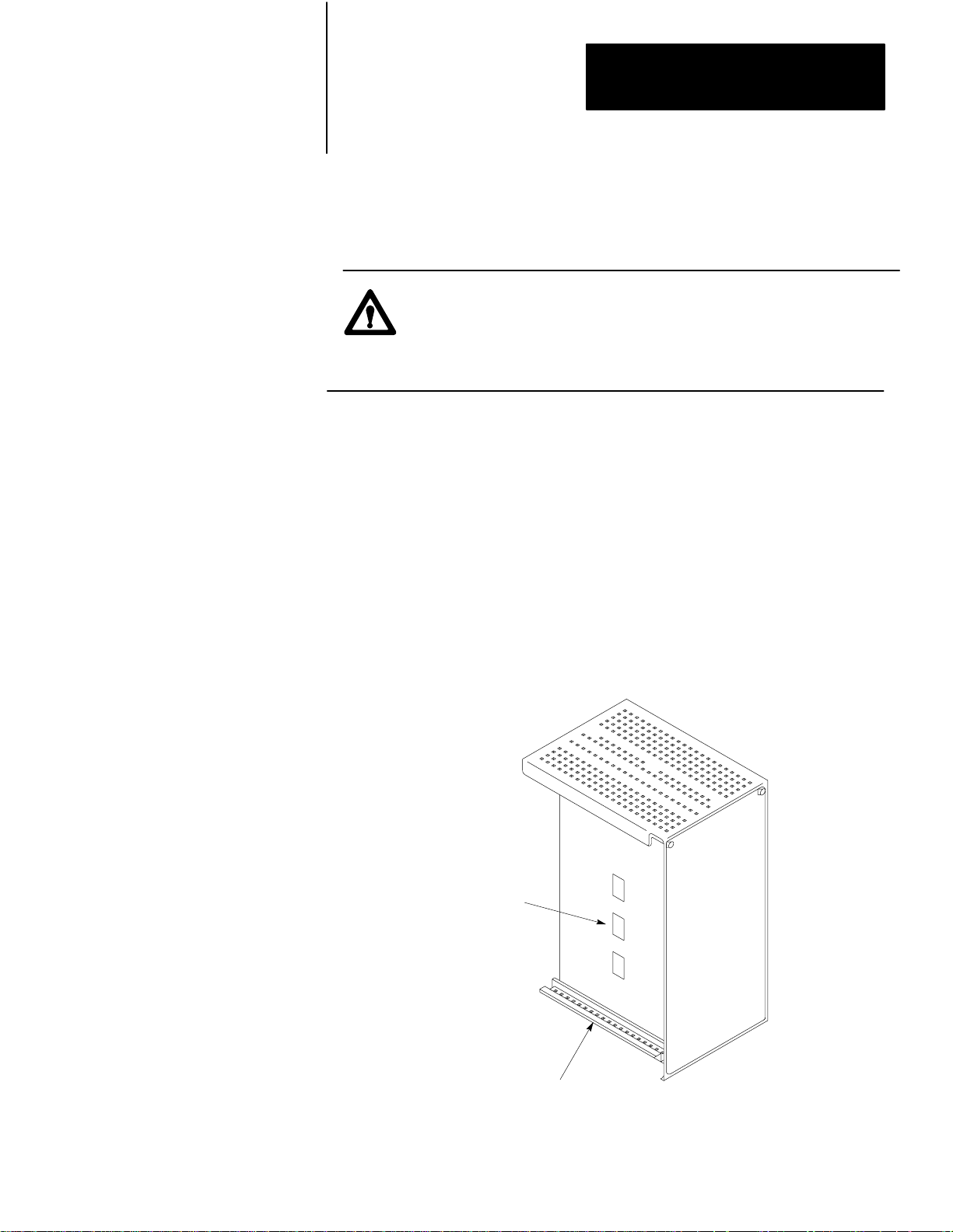
You mount the 1779-KP5 in an enclosure. The temperature of the air at
any point directly below the module must not exceed 60
Otherwise, the failure rate of semiconductor devices may increase
significantly.
The temperature tends to be higher toward the top of the enclosure. In
addition, the following factors affect the temperature in an enclosure:
The Size of the Enclosure (Smaller enclosures heat up faster.)
How Much Heat Is Being Dissipated in the Enclosure
The Temperature of the Air Surrounding the Enclosure
o
C (140oF).
Heat dissipation includes not only the heat dissipated through the power
supplies for your equipment but also the heat dissipated through input and
outputcircuits.
To allow necessary air flow for cooling of components, refer to the
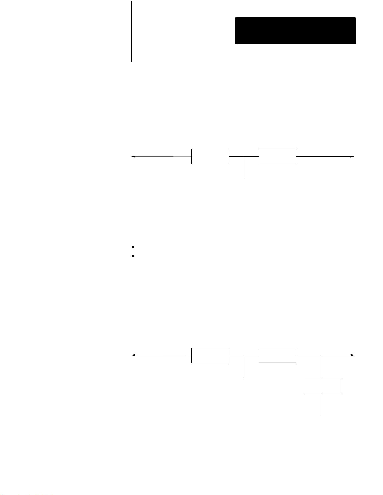
example shown in Figure 3.1 and follow these rules:
Provide six inches minimum vertical separation and four inches
horizontalseparationbetweencomponents.
Provide six inches minimum vertical separation between a chassis and
the top or bottom of the enclosure.
Provide four inches minimum horizontal separation between chassis
and to enclosure sides.
If you have excess space in the enclosure, leave it at the top of the
enclosure where the temperature is higher.
Mount wiring ducts, taps, and terminal strips no closer than two inches
from any chassis.
31
Page 15
Chapter 3
Installing the 1779KP5 Module
Figure 3.1
Example
4”
1
of Minimum Spacing for Necessary Air Flow
6”
6”
4”
4”
6”
6”
4”
32
6”
The temperature of the air must not exceed 60°C (140°F) at any point immediately below
1
any chassis. This may limit how high chassis can be mounted in an enclosure.
16007
Page 16
Chapter 3
Installing the 1779KP5 Module
Figure 3.2 shows the mounting dimensions for the 1779-KP5 interface.
Figure 3.2
Mounting
Dimensions
Use 0.25 in.
mounting bolts
(3 places)
14.25 in.
(362 mm)
3.8 in
(97 mm)
1.9 in.
(48mm)
15.25 in.
(387 mm)
6.5 in.
(165 mm)
Clearance depth including cable connectors is 11 inches (280 mm).
16008
Drill and tap the three holes in the enclosure back panel for mounting the
module. Insert the mounting bolt into the bottom hole. You can then hold
the interface in place, resting it on the bottom bolt, while you insert the
top mounting bolts.
33
Page 17
Chapter 3
Installing the 1779KP5 Module
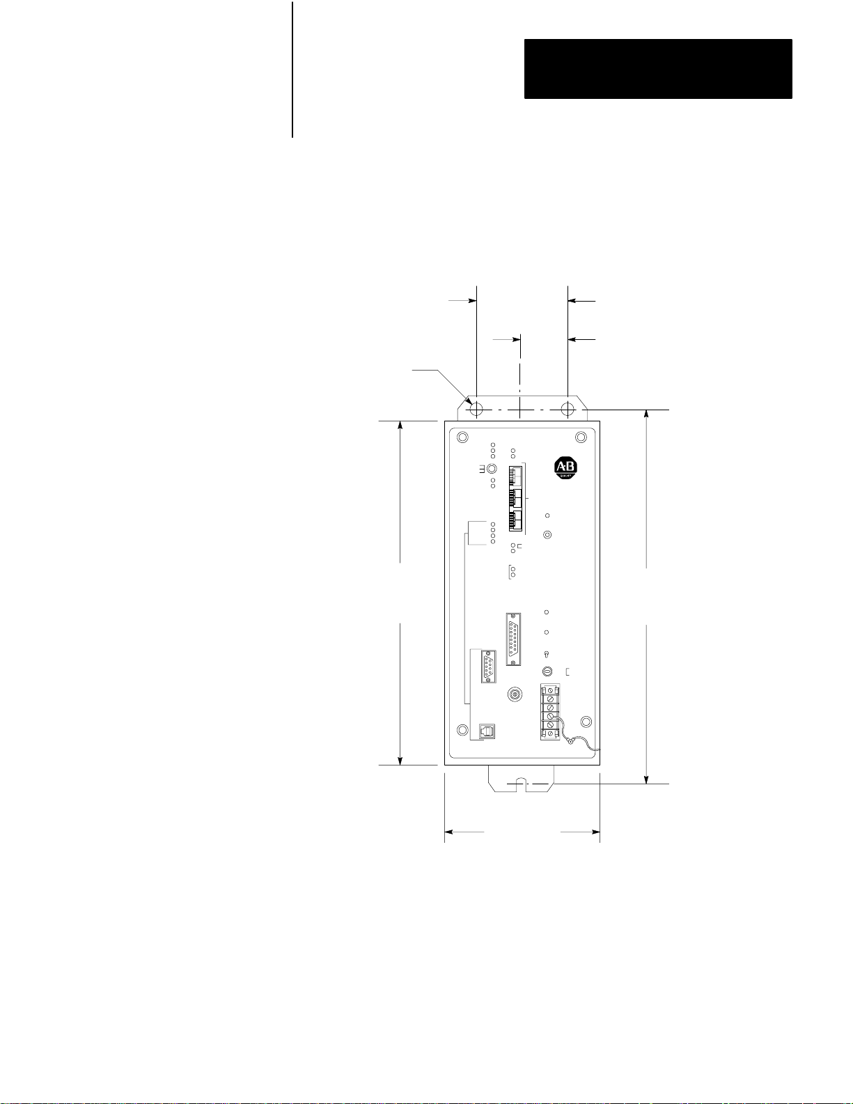
Setting the Node Address
Set the node address for your module using the three thumbwheels on the
front panel of your module (Figure 3.3).
Figure 3.3
Address
Thumbwheels on the Front Panel of the Module
NODE PASS
HOST FAULT
NODE TEST
TEST
RUN
RESET
SAT
ACTIVITY
TRANSMIT
RECEIVE
READY
ERROR
MAC FAULT
MAC TEST
MSD
LINK
ADDRESS
G IN RING
Y SEEKING MEM
ADDR
DUP
EXIT
COMPLETE
EXIT
REQUEST
34
16009
Set these thumbwheels to designate the node address of the 1779-KP5 for
both Data Highway II and Data Highway Plus. The top thumbwheel
represents the most significant digit (MSD). Set this digit to zero, since
the highest address available to a Data Highway Plus node is 077 (octal).
The bottom two thumbwheels do not go past the digit seven because the
address must be an octal number. Each node on your network must have
a unique address.
Important: The 1770-T3 industrial terminal (for the PLC-2) cannot
communicate with Addresses 000 through 007 and Addresses 100 through
107 (octal). If you have PLC-2s on your Data Highway II network, you
may not want to use these node addresses.
Page 18
Chapter 3
Installing the 1779KP5 Module
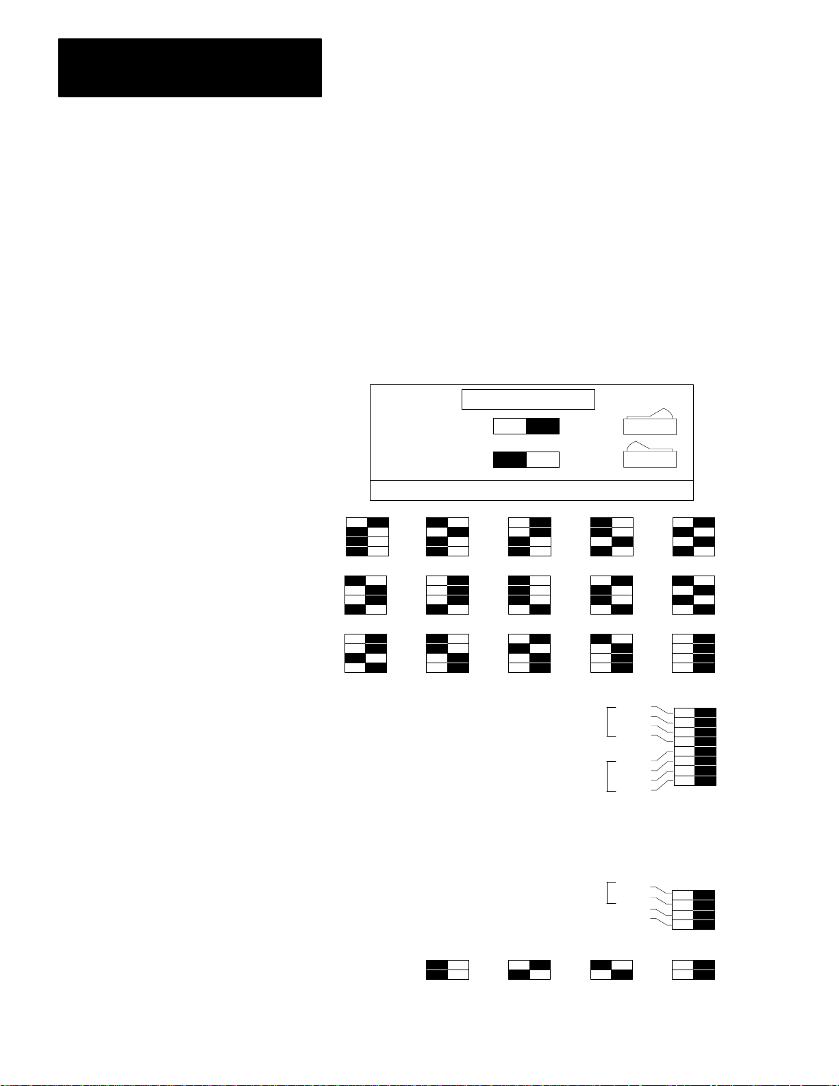
Setting the Option Switches
There are three sets of switches (labeled S-2, S-4, and S-5) on the
1779-KP5 host board. Use the following procedure to access these
switches:
CAUTION: Electrostatic discharge can degrade performance or
cause permanent damage to the module. To minimize or
prevent electrostatic discharge damage, handle the module at a
static-safe workstation.
If a static-safe workstation is not available, touch and remain in contact
with a grounded object to discharge yourself while handling the module.
1. Make sure that you remove all power to the module. Usually, you
remove power to the 1779-KP5 by locking open the main disconnect
switch on your enclosure.
2. Loosen the four fasteners on the front panel of the module. Pull the
removable frame out to the switch-setting position. This exposes the
switch assemblies.
Dip Switches
Removable Frame
S2S4S5
16010
35
Page 19
Chapter 3
Installing the 1779KP5 Module
3. After you finish setting switches, push the removable frame back to
the operating position and tighten the four fasteners on the front of
the module. The fasteners must be tight to ensure that AC power is
not interrupted by the interlock switch on the power-supply board.
Figure 3.4 shows the switch-setting label on the side of the 1779-KP5.
Figure 3.4
SwitchSetting
Label on the 1779KP5
1779KP5/KP5R
LEGEND
Option Enabled
Option Disabled
ON
ON OFF
ON OFF
White Is Depressed
1 2
3 4 5
6 7 8 9 10
11 12 13 14 15
DH+ LINK
LSB
ADDRESS
DHII LINK
LSB
ADDRESS
OFF
S2
1
2
3
4
5
6
7
8
36
ROUTE UPDATE
DHII
DH+
S4
Reserved 3
Reserved 4
S5
Not Used 230.4K 115.2K 57.6K
BAUD RATE SELECT
OPEN (OFF)
1
2
3
4
1
2
16484
Page 20
Chapter 3
Installing the 1779KP5 Module
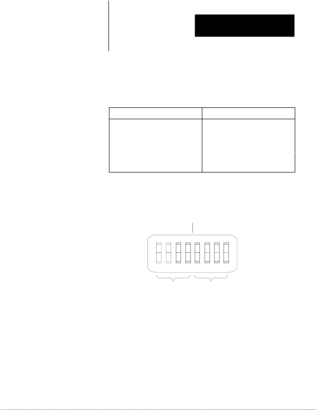
Switch Assembly S2: Link Address
You use Switch Assembly S-2 to set a unique link address (between 1 and
15) for both the Data Highway II and Data Highway Plus links connected
to the 1779-KP5 in a bridge configuration. The 1779-KP5 uses these link
addresses to route messages. Refer to the following table:
If You Are Using:
A 1779KP5 in a Bridge Configuration to
Connect T
A 1779KP5 as a Data Highway II/Data
Highway Plus Interface Using Local
Addressing
A 1779KP5 as a Data Highway II/Data
Highway Plus Interface Using Remote
Addressing
wo Data Highway II Links
Y
ou need to assign link addresses (using DIP
switches).
Y
ou do not assign link addresses.
Y
ou need to assign link addresses (using
stationmanagement commands).
Then:
Refer to Chapters 4 and 5 for more information on addressing.
Switch Value
(When ON)
12481248
12
345678
OPEN
Data Highway Plus
(Switch 1 is the
least significant bit.)
Data Highway II
(Switch 5 is the
least significant bit.)
16498
Important: Do not set the link number to zero unless you only have one
Data Highway II link on the network. The 1779-KP5 uses link zero to
signify the local link message.
37
Page 21
Chapter 3
Installing the 1779KP5 Module
For example, to set a Data Highway Plus link address of 5 and a Data
Highway II link address of 6, you would set the switches as follows:
12
345678
OPEN
1 + 4
5
2 + 4
6
16499
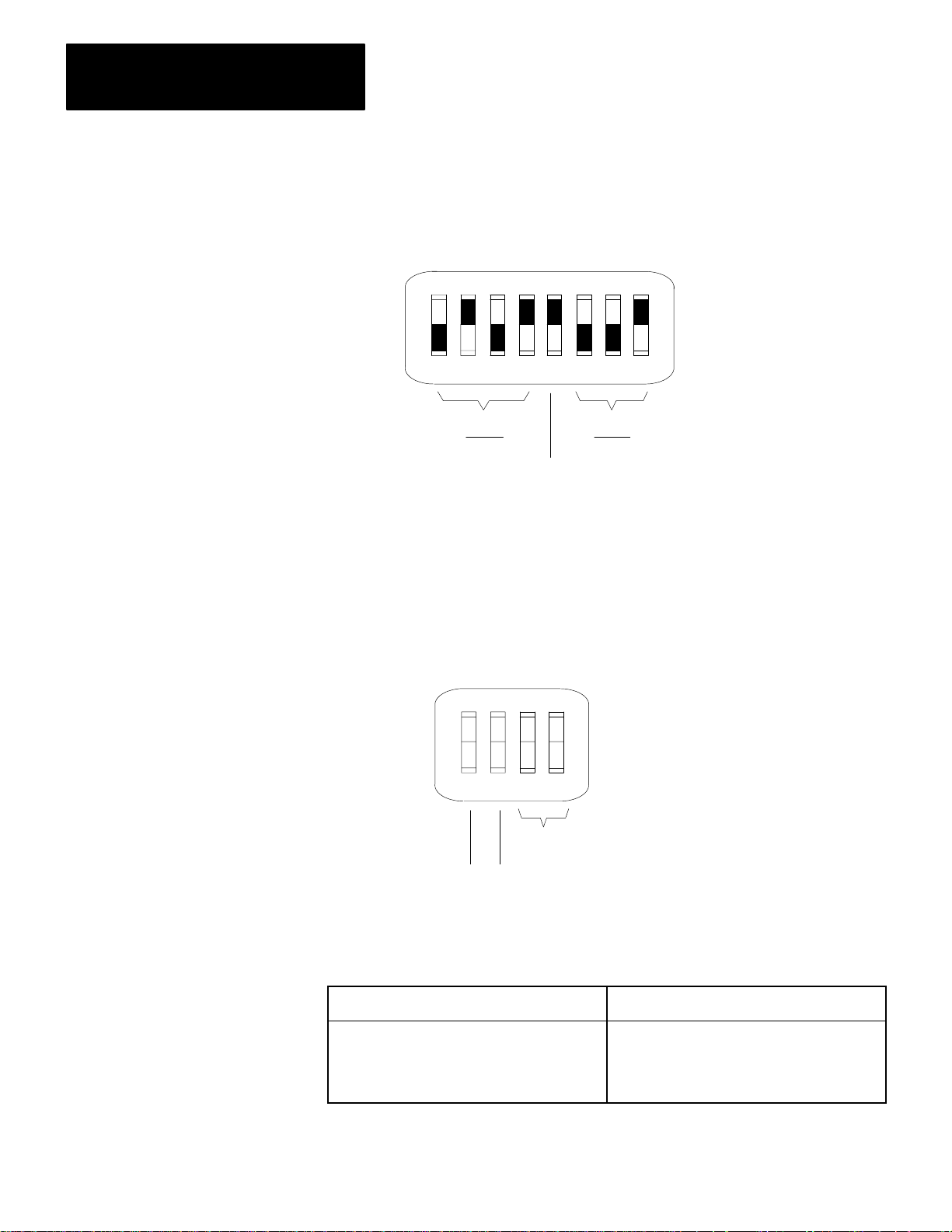
Switch Assembly S4: Enable/Disable Route Update
You use Switch Assembly S-4 to enable or disable the route update
message on your network.
12
34
When you press a
switch
towards the word OPEN,
you turn the switch ON.
OPEN
38
Reserved
Route Update
Enable/Disable
If You Are Using:
A 1779KP5 as an Interface between a Data
Highway Plus Link and Data Highway II
A 1779KP5 in a Bridge Configuration
16500
Then:
Disable Route Updates
(Both Switches OFF Closed)
Enable Route Updates
(Both Switches ON Open)
Page 22
Chapter 3
Installing the 1779KP5 Module
Switch Assembly S5: Data Highway Plus Communication Rate
You use the set of switches labeled S-5 to set the Data Highway Plus
communication rate. You must set both these switches ON (toward the
word OPEN) for a communication rate of 57.6 Kbits per second.
Setting the PowerSelection
Switch
12
OPEN
Set both switches ON
(toward the word OPEN) for
57.6K baud.
Set Switch 1 ON and Switch 2
OFF for 115.2K baud. (This
setting can be used only
when you are using two
modules in bridge mode.)
16501
Before connecting power, make sure the power-selection switch on the
power-supply board is set properly by following these steps:
CAUTION: Electrostatic discharge can degrade performance or
cause permanent damage to the module. To minimize or
prevent electrostatic discharge damage, handle the module at a
static-safe workstation.
If a static-safe workstation is not available, touch and remain in
contact with a grounded object while handling the module.
1. If you are resetting the switch, make sure that you remove all power
to the module. Usually, you remove power to the 1779-KP5 by
locking open the main disconnect switch on your enclosure.
2. Loosen the four fasteners on the front panel of the module. Pull the
removable frame out to the switch-setting position. This exposes the
power-selection switch on the power-supply board.
39
Page 23

Chapter 3
Installing the 1779KP5 Module
Setting the Data Highway Plus Terminating Resistor
115V
Push switch down for
230V operation.
16011
3. Set the voltage-selection switch to correspond to the level
(115V/230V) of your AC power source. The module is factory set to
115V AC.
4. Push the removable frame back to the operating position and tighten
the four fasteners on the front of the module. The fasteners must be
tight to ensure that AC power is not interrupted by the interlock
switch on the power-supply board.
The 1779-KP5 provides a jumper which sets a terminating resistor for
Data Highway Plus. If you are using two 1779-KP5 modules in a bridge
configuration, set this jumper on each module. The jumper terminates the
Data Highway Plus link that runs between the two modules.
310
Use the following procedure to set the resistor:
Page 24

Chapter 3
Installing the 1779KP5 Module
CAUTION: Electrostatic discharge can degrade performance or
cause permanent damage to the module. To minimize or
prevent electrostatic discharge damage, handle the module at a
static-safe workstation.
If a static-safe workstation is not available, touch and remain in
contact with a grounded object to discharge yourself while
handling the module.
1. Make sure that you remove all power to the module. Usually, you
remove power to the 1779-KP5 by locking open the main disconnect
switch on your enclosure.
R47
150
JPR2
2. Loosen the four fasteners on the front panel of the module. Pull the
removable frame out to the switch-setting position. This exposes the
resistor.
Ω
Jumper in upper
position terminates
Data Highway Plus
link.
Removable Frame
16012
311
Page 25

Chapter 3
Installing the 1779KP5 Module
3. After you finish setting the resistor, push the removable frame back
to the operating position and tighten the four fasteners on the front of
the module. The fasteners must be tight to ensure that AC power is
not interrupted by the interlock switch on the power-supply board.
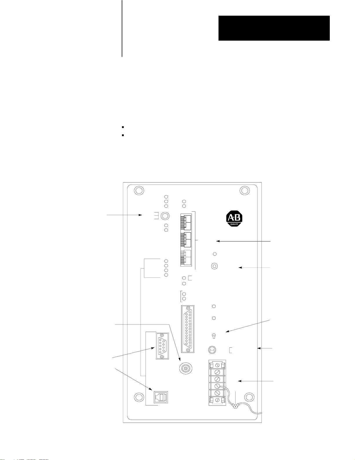
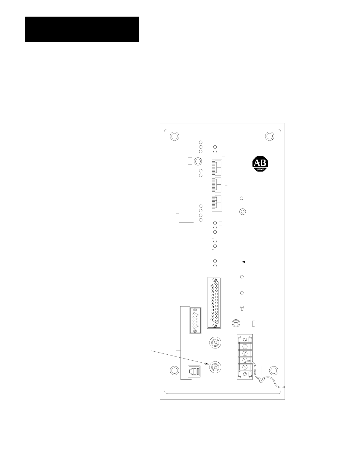
Connecting Communication Cables
After you have set the switches and the terminator, you can connect the
communication cables necessary for your application.
The following sections provide information for connecting the 1779-KP5
to:
Data Highway II
Data Highway Plus
1784-T50 Industrial Terminal
CAUTION: The DHII AUX ACCESS connector on the front
panel of the module is for future product enhancement. To help
protect this connector from electrostatic discharge, make sure
that the conductive cap (shipped with the module) remains on
theconnector.
Connecting the Data Highway II and Data Highway Plus
The 1779-KP5 has a connector for the Data Highway II network and a
connector for the Data Highway Plus network. You must connect a drop
cable from each network to the 1779-KP5 (Figure 3.5).
312
If you have a 1779-KP5R, you must connect a drop cable for each Data
Highway II cable system.
The drop cable for Data Highway II is provided with the Data Highway II
tap (Cat. No. 1779-XP). For more information on Data Highway II
cabling, refer to the Data Highway II Cable Planning and Installation
Manual (Publication1779-6.5.7).
Page 26

Chapter 3
Installing the 1779KP5 Module
Figure 3.5
Connections
Data Highway Plus
Connector
to the Networks on the 1779KP5
1784-T50
Connector
Data Highway II
Connector
DC POWER ON
1
II
AC POWER ON
ON
AC POWER
OFF
SLOW BLOW
FUSE
2A, 250V
115V AC/230V AC
INTERNALLY
SWITCH
SELECTABLE
L1
L2/N
GND
DAT A
HWY
PLUS
DH II
AUX
ACCESS
DATA
HWY
PORT
CAT. NO. 1779-KP5 DHII/DH+ INTERFACE
16013
You must construct a Data Highway Plus drop cable using the following
pinout information:
User-Supplied Cable
Belden 9463 or Equivalent
(100 Ft. Max.)
3-Pin
Data Highway Plus
Terminal Block
1
SH
2
Data Highway Plus
Connection
1
SH
2
15728
For more information on Data Highway Plus cabling, refer to the Data
Highway Cable Assembly and Installation Manual
(Publication 1770-6.2.1).
313
Page 27

Chapter 3
Installing the 1779KP5 Module
Connecting a T50 Industrial Terminal
You can connect a T50 Industrial Terminal (Cat. No. 1784-T50) to the
1779-KP5 for use on the Data Highway Plus network. To connect the
T50 to the 1779-KP5, you can use a 1784-CP5 cable, or you can construct
a cable using the following pinout:
User-Supplied Cable
Belden 9463 or Equivalent
(10 Ft. Max.)
Connecting Power and Ground
15-Pin Female
Data Highway Plus
Interface Module
Connector of T50
Connector
6
7
8
13
15
User-Supplied
Female Connectors
9-Pin Female
Connector
5
7
1
Top
Data Highway Plus
Connector on
1779-KP5
15729
After you mount the 1779-KP5 module and set the switches and jumper,
you connect the module to power and ground. The following sections
contain:
Guidelines for Power Distribution
A Procedure for Connecting Power and Ground to the Terminal Block
314
PowerDistribution Guidelines
Allen-Bradley power supplies have circuits that suppress electromagnetic
interference from other equipment. For installations near particularly bad
electrical noise generators, an isolation transformer can provide further
suppression of electromagnetic interference from other equipment.
In applications where the AC power source is subject to unusual
variations, a constant-voltage transformer can stabilize the AC power
source to the interface, thereby minimizing shutdowns.
Page 28

Chapter 3
Installing the 1779KP5 Module
To provide AC power isolation between the 1779-KP5 and other
equipment, connect a separate transformer between the module’s power
supply and the AC power source. Connect the:
Transformer primary to the AC source.
High side of the transformer secondary to the L1 terminal of the power
supply.
Low side of the transformer secondary to the L2/N terminal of the
power supply.
The 1779-KP5 consumes 50 watts of power. To determine the required
rating of the transformer, multiply the power requirements of the
Allen-Bradley power supplies by 2.5 and add all other power
requirements (input circuits, output circuits). Take into consideration the
surge currents of devices controlled by the controller when determining
power requirements. The minimum transformer rating requirement for
the 1779-KP5 interface is 125 VA.
The 115V AC power supplies on Allen-Bradley modules are designed to
shut down whenever the AC line voltage drops below 85V. The power
supply allows the interface to resume operation when the line voltage
reaches 85V again. The 230V AC power supplies on Allen-Bradley
modules shut down at 170V AC.
If the transformer is too small, it clips the peak of the sine wave before the
voltage drops below 85 volts. The power supply senses this as a low
voltage and shuts down the interface prematurely.
Connecting Power and Ground to the Terminal Strip
1. Make sure that you remove all power to the enclosure. Usually, you
remove power by locking open the main disconnect switch on your
enclosure.
WARNING: Do not connect power to the power terminals
without first removing power from the enclosure. Otherwise,
you may be injured by electrical shock.
315
Page 29

Chapter 3
Installing the 1779KP5 Module
2. Connect the GND post on the module to the central ground bus of
your enclosure.
115V AC/230V AC
INTERNALLY
SWITCH
SELECTABLE
L1
L2/N
GND
INTERFACE
Green
Grounding Conductor
GND Post
Central Ground Bus
of Enclosure
Earth
Ground
16014
The interface is shipped to you with a wire connecting the post to the
stationary frame and another wire connecting the post to the GND
terminal of the terminal block. When you ground the post on the
removable frame, you thereby also ground the stationary frame and
the power-supply board.
Follow all applicable codes and standards when you ground the
module. Refer to the National Electric Code published by the
National Fire Protection Association of Boston for more information.
Refer to Article 250 of the code for sizes and types of conductors and
methods of safely grounding electrical components.
316
3. Connect the L2/N terminal to the low side of the transformer
supplying the AC power. Then connect the L1 terminal to the high
side of the transformer supplying the AC power.
4. Install the terminal cover (supplied with your module) over the
terminal block.
WARNING: Do not leave the terminal block exposed.
Otherwise, you may touch these terminals and be injured by an
electrical shock.
Page 30

Chapter 3
Installing the 1779KP5 Module
Powering Up the 1779KP5
Interface
To power up the 1779-KP5, use the following procedure:
1. Set the AC POWER switch on the front panel of the module to OFF.
AC POWER ON
DATA
HWY
PORT
DAT A
HWY
PORT
ON
AC POWER
OFF
SLOW BLOW
FUSE
2A. 250V
115V AC/ 230V AC
INTERNALLY
SWITCH
II
1
II
2
SELECTABLE
L1
L2/N
GND
AC Power
Switch
1779-KP5R DHII/DH+ INTERFACE
16015
2. Restore power to the 1779-KP5. Usually, this means you must close
the main disconnect switch on the enclosure containing the
1779-KP5.
3. Set the AC POWER switch to ON.
When you power up the 1779-KP5, all the diagnostic LEDs on the
interface flash briefly as the module executes power-up diagnostics.
The LEDs should then switch to normal operation.
Refer to Chapter 6 for:
A More Complete Description of the LED Indicators
A Description of Troubleshooting Tools You Have Available
317
Page 31

Chapter
4
Addressing from Data Highway II
Chapter Objectives
Limitations on Sending Commands
In this chapter, we provide a description of how to address the following
links from a node on Data Highway II:
A Data Highway Plus Link Using Local Link Addressing (Link = 0)
Another Data Highway II Link Using Remote Link Addressing
(Link > 0)
A Data Highway Plus Link Using Remote Link Addressing (Link > 0)
The 1779-KP5 does not support Data Highway II time-critical commands
because these commands are not supported by Data Highway Plus. The
1779-KP5 rejects time-critical commands and returns an error reply to the
initiating node. For more information on error codes, refer to your
interface manual and Chapter 6 of this manual.
The 1779-KP5 replies to the following diagnostic commands from a Data
Highway II node:
Diagnostic Status
Diagnostic Loop
The 1779-KP5 does not contain Data Highway II diagnostic counters.
This is because Data Highway II counters are application layer counters
and the 1779-KP5 does not provide application layer functions.
Refer to Chapter 6 for a list of 1779-KP5 diagnostic status bytes.
41
Page 32

Chapter 4
Addressing from Data Highway II
Addressing a Data Highway Plus Node Using Local Addressing
You use local addressing to communicate with a node on a local Data
Highway Plus link. A local Data Highway Plus link:
Is directly connected to the Data Highway II link you are
communicating from.
Has a link value of zero.
Figure 4.1 shows an example of a configuration which uses local
addressing.
Figure 4.1
Addressing Configuration
Local
Data Highway II
Sending
Node
1779KP5
PLC5
Plus
1784T50
PLC5Data Highway
16487
Important: A computer on Data Highway Plus cannot address a node on
a remote link such as Data Highway II.
When you use local addressing to address a Data Highway Plus node, you
can only use Addresses 01 through 20 (octal) on the Data Highway Plus
link.
When you use local addressing, you use the LINK, NODE, and USER
fields to specify the node address.
The LINK value is always zero for local commands.
42
Page 33

Chapter 4
Addressing from Data Highway II
The NODE value for each Data Highway Plus node is the same as the
node address of the 1779-KP5 it is connected to (between 01 and
77 octal). Refer to Chapter 3 for information on setting the node address
of a 1779-KP5 using the thumbwheels on the front panel.
For example, if the NODE value of the 1779-KP5 is 50 (octal), the NODE
value of each Data Highway Plus node connected to it is also 50.
The USER value is the Data Highway Plus node address. The USER
value must be between two and 20 (octal).
The 1779-KP5 reserves USER 01 to identify itself to nodes on Data
Highway II. You can still use Data Highway Plus Address 01 (the
1784-T50 default address), but Data Highway II nodes will not be able to
communicate to this Data Highway Plus node.
For example, a Data Highway Plus node, Address 15 (octal), connected to
the 1779-KP5 at:
LINK
00
NODE
50
would have the Data Highway II address:
LINK
00
NODE
50
USER
15
Important: Due to PLC-2 address limitations, the USER value you use
when sending a command from a 1779-KP2 does not equal the Data
Highway Plus address. For more information, refer to the following
section on PLC-2 addressing. If you are using a 1779-KP2 to
communicate to Data Highway Plus, make sure that the 1779-KP5 node
address is not 00 to 07. The 1770-T3 terminal cannot communicate to
these addresses.
The following sections provide guidelines for addressing Data Highway
Plus nodes from Data Highway II using local addressing.
43
Page 34

Chapter 4
Addressing from Data Highway II
Addressing Data Highway Plus from a PLC2
To send a message from a PLC-2 (1779-KP2) on Data Highway II to a
Data Highway Plus node, you use the following address format in the
communication zone of your ladder-logic program (NNN = Node,
UUU = User):
NNN UUU
=
The 1779-KP2 does not support the network layer. The LINK value is
automatically 00 (local link).
The NODE value is the node address of the 1779-KP5 that connects you
to the destination Data Highway Plus link (the link that contains the node
you want to communicate with).
The PLC-2 USER value is determined differently than for other nodes on
Data Highway II. Since a PLC-2 cannot send to Addresses 00 to 07 octal
(these addresses are defined by the PLC-2 for processor work area), a
PLC-2’s access to other node addresses would be extremely limited (only
Stations 10 through 20 octal). To solve this problem, the PLC-2 uses a
formula to convert the node addresses. This allows the PLC-2 to access
all allowable addresses (02 through 20 octal) on Data Highway Plus.
To determine the PLC-2 USER value of a Data Highway Plus node, add
10 (octal) to the Data Highway Plus address. For example, Data Highway
Plus Node 12 (octal) has a PLC-2 USER value of 22:
12 + 10 = 22 (octal)
For more information on addressing a PLC-2 on Data Highway II, refer to
the PLC-2 Family Interface (1779-KP2, -KP2R) User’s Manual
(Publication 1779-6.5.3).
44
Page 35

Chapter 4
Addressing from Data Highway II
Addressing Data Highway Plus from a PLC3
To send a message from a PLC-3 (1779-KP3) on Data Highway II to a
Data Highway Plus node, you use the following address format in the
message instruction of your ladder-logic program (NNN = Node,
UUU = User):
:NNN.UUU
The 1779-KP3 does not support the network layer. The LINK value is
automatically 00 (local link).
The NODE value is the node address of the 1779-KP5 that connects you
to the destination Data Highway Plus link (the link that contains the node
you want to communicate with).
The USER value is the Data Highway Plus address of the node you want
to communicate with.
For example, a PLC-3 message instruction to read a file from a PLC-5:
with Data Highway Plus Address 012 (octal)
connected to the 1779-KP5 with a Data Highway II address of 045
(octal)
would look like this:
MOVE FROM :45.12$E0.10.0.0 TO $N10:0,20
If you are communicating to a PLC-5, you need to send a PLC-5
four-level address instead of a six-level address:
Address
Level
1
2 Context
3 Section Element
4 File SubElement
5 Structure
6 Word
PLC3 PLC5
Major Section
3 = Data T
able
Major Section
0 = Data T
File Number
(Must Be 0 15)
able
45
Page 36

Chapter 4
Addressing from Data Highway II
Important: If you use a file value of greater than 15, the value wraps
around to zero. For example, a value of 16 specifies File 0, a value of 17
specifies File 1, etc.
You must enter the PLC-5 address in the following address format:
$ E [Major Section] . [File #] . [Element] . [Sub-Element]
If you send a full PLC-3 six-level address to a PLC-5, the PLC-5 will
return an error.
Addressing Data Highway Plus from a 1779KFL or 1779KFM Device
To address a Data Highway Plus node from a programmable device
connected to a 1779-KFL, -KFLR or 1779-KFM, -KFMR, the device
must enter the appropriate LINK, NODE, and USER values in the
message packet.
The LINK value is always 00 for local addressing.
The NODE value is the node address of the 1779-KP5 that connects you
to the destination Data Highway Plus link (the link that contains the node
you want to communicate with).
The USER value is the Data Highway Plus address of the node you want
to communicate with.
For example, if you send a message to:
a PLC-5 at Address 13 (octal)
on a Data Highway Plus connected to a 1779-KP5 with the Data
Highway II Node Address 16 (octal)
your message packet looks similar to this:
EXTSEL USER13CMD STS TNSSTSFF TNS
LINK
00
NODE
16
46
Page 37

Chapter 4
Addressing from Data Highway II
A computer with Data Highway (DF1) driver connected to a 1779-KFL in
KE/KF emulation mode will only be able to address a single Data
Highway Plus node. This Data Highway Plus node must have a Data
Highway Plus address of 002.
Can Only Address Data
Highway Plus Node (USER) 2
Computer
(in KE/KF
Mode)
1779KFL
Data Highway II
Data Highway Plus
Can Address All Legal
Data Highway Plus Nodes
Computer
(in Native
Mode)
USER 3
1779KP5
USER 4USER 2
16488
Addressing a Remote Data Highway II Node Using Remote Addressing
Figure 4.2 shows an example configuration showing two 1779-KP5
modules used as a bridge between two Data Highway II links.
Important: Only Series B modules support communication between two
Data Highway II links. The PLC-2 Family Interface (1779-KP2, -KP2R)
and the PLC-3 Family Interface (1779-KP3, -KP3R) do not offer a
Series B version.
Figure 4.2
Bridging
between Two Data Highway Ii Networks
1779KP5
Data Highway Plus
(Do not attach nodes when used in bridge configuration.)
1779KP5
Data Highway IIData Highway II
16489
47
Page 38

Chapter 4
Addressing from Data Highway II
When you send a message from a node on your Data Highway II link to a
node on a remote Data Highway II link, you address the node using the
LINK, NODE, and USER fields.
Use the LINK field to specify what link the remote node is on. The
LINK value of a remote link can be between 1 and 15. You set the link
value of a remote link using switches on the remote link’s 1779-KP5
(Chapter 3).
Use the NODE and USER fields the same way as normal Data
Highway II addressing. The NODE field specifies the node address on
the remote link. The USER field specifies the user on the remote node.
For example, if you want to send a message to:
Addressing a Remote Data Highway Plus Using Remote Addressing
User 1
on a 1779-KFL with Node Address 17
on Remote Link 13
your address fields would like like this:
LINK
13
NODE
17
USER
01
You use remote addressing to communicate with a node on a remote Data
Highway Plus link. A remote Data Highway Plus link has a link value
greater than zero.
Important: Only Series B Data Highway II modules support
communication to a remote Data Highway Plus link. The PLC-2 Family
Interface (1779-KP2, -KP2R) and the PLC-3 Family Interface (1779-KP3,
-KP3R) do not offer a Series B version.
48
Figure 4.3 shows an example of a configuration which uses remote
addressing.
Page 39

Figure 4.3
Addressing Configuration
Remote
Chapter 4
Addressing from Data Highway II
Data Highway II
Sending
Node
1779KP5 1779KP5
Data Highway Plus
(Do not attach nodes
when used in bridge
configuration.)
Plus
Data Highway II
1779KP5
PLC5
PLC5Data Highway
1784T50
16490
There are two ways to communicate to a remote Data Highway Plus link:
Using a Remote Data Highway II Link Number
Using a Remote Data Highway Plus Link Number
The following sections show these two methods.
Using a Data Highway II Link Number
When you use the Data Highway II link number, you can only address
Nodes 02 through 20 (octal) on the Data Highway Plus link.
You use the LINK, NODE, and USER fields to specify the Data Highway
Plus node address.
Figure 4.4 shows an example address using the Data Highway II link
number.
49
Page 40

Chapter 4
Addressing from Data Highway II
Figure 4.4
Addressing
a Remote Data Highway Plus Node Using a Data Highway II Link Number
Link = 01 Link = 02 Link = 03
Data Highway II
Sending
Node
1779KP5 1779KP5
Data Highway Plus
(Do not attach nodes
when used in bridge
configuration.)
Plus
Data Highway II
1779KP5
1784T50
Link = 03
Node = 42
User = 01
PLC5
PLC5Data Highway
Link = 03
Node = 42
User = 03
Link = 03
Node = 42
User = 04
16491
The LINK value is the link value of the remote Data Highway II link to
which the Data Highway Plus link is attached. The LINK value of a
remote link can be between 1 and 15. You set the link value of a Data
Highway II link using switches on the remote link’s 1779-KP5
(Chapter 3).
The NODE value for each Data Highway Plus node is the same as the
Data Highway II node address of the 1779-KP5 it is connected to. Refer
to Chapter 3 for information on setting the node address of a 1779-KP5
using the thumbwheels on the front panel.
For example, if the NODE value of the 1779-KP5 is 42 (octal), the NODE
value of each Data Highway Plus node connected to it is also 42.
The USER value is the Data Highway Plus node address. The USER
value must be between 1 and 20 (octal).
The 1779-KP5 reserves USER 01 to identify itself to nodes on Data
Highway II. You can still use Data Highway Plus Address 001 (the
1784-T50 default address), but Data Highway II nodes will not be able to
communicate to this Data Highway Plus node.
410
Page 41

Chapter 4
Addressing from Data Highway II
Using a Data Highway Plus Link Number
When you use a Data Highway Plus link number, you can address up to
64 nodes to your Data Highway Plus link.
To use a Data Highway Plus link number to address a Data Highway Plus
node, you must:
Not enable the route update messages. This means that your 1779-KP5
can receive route updates, but it cannot send a route update to inform
other 1779-KP5 modules on where to find the Data Highway Plus link.
Use station-management commands to send the routes from an
intelligent device on your network to the other 1779-KP5 modules.
When your device sends the FIXED ROUTE to all local 1779-KP5
modules, these modules will update the route for all other links on the
network. For more information, refer to your 1779-KFL, -KFLR or
1779-KFM, -KFMR documentation.
You use the LINK, NODE, and USER fields to specify the Data Highway
Plus node address.
Figure 4.5 shows an example address using the Data Highway Plus link
number.
Figure 4.5
Addressing
a Remote Data Highway Plus Node Using a Data Highway Plus Link Number
Link = 01 Link = 02 Link = 03
Data Highway II
Sending
Node
1779KP5 1779KP5
Data Highway Plus
(Do not attach nodes
when used in bridge
configuration.)
Plus
Link = 04
Data Highway II
1779KP5
PLC5
PLC5Data Highway
Node = 42
Link = 04
Node = 03
User = 01
Link = 04
Node = 04
User = 01
1784T50
16492
411
Page 42

Chapter 4
Addressing from Data Highway II
The LINK number is the LINK number you have set on your 1779-KP5
for the Data Highway Plus link (Chapter 3).
The NODE number is the destination node’s Data Highway Plus address.
The USER number must be 1.
412
Page 43

Chapter
5
Addressing from Data Highway Plus
Chapter Objectives
Limitations on Sending Commands
Addressing a Local Data Highway II Node Using Local Addressing
In this chapter, we provide a description of how to address nodes on:
Data Highway II from nodes from Data Highway Plus.
Another Data Highway Plus connected to the same Data Highway II
network.
Another Data Highway Plus connected to a remote Data Highway II
network.
The 1779-KP5 replies to the following diagnostic commands from a Data
Highway Plus node:
DiagnosticStatus
DiagnosticRead
Reset Diagnostic Counters
DiagnosticLoop
Refer to Chapter 6 for a list of 1779-KP5 diagnostic counters and
diagnosticstatusbytes.
This section describes how you address a local Data Highway II node. A
local Data Highway II node is a node on the Data Highway II link directly
connected to the Data Highway Plus link through a 1779-KP5. Figure 5.1
shows an example configuration.
51
Page 44

Chapter 5
Addressing from Data Highway Plus
Figure 5.1
Highway II and Data Highway Plus Configuration
Data
Data Highway II
1779KFL
Plus
1779KP5
1784T50
PLC5
PLC5Data Highway
16493
When you send a message to a Data Highway II node from Data Highway
Plus, you specify the address using the LINK, NODE, and USER fields
the same way as the normal Data Highway II addressing.
The LINK value for local addressing is always zero.
The NODE value of a Data Highway II node is the node address you set
on the module using the thumbwheels on the front panel.
The default USER value for all Data Highway II devices is 01. For a
1779-KFL module, the devices will have USER values of 01 and 02.
52
For example, a Data Highway II node, Address 15, connected to a
1779-KFL User 2, would have the address:
LINK
00
NODE
15
USER
02
Important: The address of the initiating Data Highway Plus node must
be between 02 and 20 (octal) so that the reply message can be returned. A
computer on Data Highway Plus cannot address a node on a remote link,
such as Data Highway II or another Data Highway Plus link.
Page 45

Chapter 5
Addressing from Data Highway Plus
You can send commands to Data Highway II from Data Highway Plus
Addresses 002 through 020 (octal). You may still assign Address 001 (the
default address for the 1784-T50) and Addresses 021 through 077 (octal)
on your Data Highway Plus network, but these nodes are unable to initiate
messages to nodes on your Data Highway II network.
In our examples, we use a 1784-T50 Industrial Terminal and Version 2.2
software to display PLC-5 commands. For more information on how to
use Version 2.1 software (or earlier), refer to Appendix B.
The following sections provide guidelines for addressing various types of
PLC and computer nodes.
Data Highway Plus to a PLC2 (1779KP2, KP2R)
The following example shows a PLC-5 message instruction that reads 64
words of data from a PLC-2 (Data Highway II Link 00, Node 010),
starting at Memory Location 200. The command stores the data at
Memory Location N100:0 in the initiating PLC-5.
MESSAGE INSTRUCTION DATA ENTRY FOR CONTROL BLOCK N13:0
Read/Write: READ
PLC-5 Data Table Address:
Size in Elements:
Local/Remote:
Remote Station:
Link ID:
Remote Link Type:
Local Node Address:
Processor Type:
Destination Data Table Address:
BLOCK SIZE = 10 WORDS
Press a key to change a parameter or <RETURN> to accept parameters.
[
Program No Forces No Edits PLC-5/15 ADDR 20
READ/
WRITE
F1
PLC-5
ADDRESS
F2
SIZE IN
ELEMENTS
F3
LOCAL/
REMOTE
F4
REMOTE
STATION
F5
N100:0
64
REMOTE
Node = 010 User = 001
00
DATA HIGHWAY II
50
PLC-2
200
LINK
ID
F6
REMOTE
LINK
F7
LOCAL
NODE
F8
PROC.
TYPE
F9
DESTIN
ADDR
F10
53
Page 46

Chapter 5
Addressing from Data Highway Plus
Data Highway Plus to a PLC3 (1779KP3, KP3R)
The following example shows a PLC-5 message instruction that reads 100
words of data from a PLC-3 (Data Highway II Link 00, Node 11), starting
at Memory Location B100:0. The command stores the data at Memory
Location N100:0 in the initiating PLC-5.
MESSAGE INSTRUCTION DATA ENTRY FOR CONTROL BLOCK N13:0
Read/Write: READ
PLC-5 Data Table Address:
Size in Elements:
Local/Remote:
Remote Station:
Link ID:
Remote Link Type:
Local Node Address:
Processor Type:
Destination Data Table Address:
BLOCK SIZE = 11 WORDS
N100:0
100
REMOTE
Node = 011 User = 001
00
DATA HIGHWAY II
50
PLC-3
B100:0
Press a key to change a parameter or <RETURN> to accept parameters.
[
Program No Forces No Edits PLC-515 ADDR 20
READ/
WRITE
F1
PLC-5
ADDRESS
F2
SIZE IN
ELEMENTS
F3
LOCAL/
REMOTE
F4
REMOTE
STATION
F5
LINK
ID
F6
REMOTE
LINK
F7
LOCAL
NODE
F8
PROC.
TYPE
F9
DESTIN
ADDR
F10
54
Page 47

Chapter 5
Addressing from Data Highway Plus
Data Highway Plus to a SynchronousDevice Interface (1779KFM, KFMR)
The following example shows a PLC-5 message instruction (displayed by
the T50) that writes 100 words of data from the PLC-5, starting at
Memory Location N100:0. The command is a PLC-2-type command and
stores the data at Memory Offset 010 in the computer.
MESSAGE INSTRUCTION DATA ENTRY FOR CONTROL BLOCK N13:0
Read/Write: WRITE
PLC-5 Data Table Address:
Size in Elements:
Local/Remote:
Remote Station:
Link ID:
Remote Link Type:
Local Node Address:
Processor Type:
Destination Data Table Address:
BLOCK SIZE = 10 WORDS
N100:0
100
REMOTE
Node = 012 User = 001
00
DATA HIGHWAY II
50
PLC-2
010
Press a key to change a parameter or <RETURN> to accept parameters.
[
Program No Forces No Edits PLC-5/15 ADDR 20
READ/
WRITE
F1
PLC-5
ADDRESS
F2
SIZE IN
ELEMENTS
F3
LOCAL/
REMOTE
F4
REMOTE
STATION
F5
LINK
ID
F6
REMOTE
LINK
F7
LOCAL
NODE
F8
PROC.
TYPE
F9
DESTIN
ADDR
F10
55
Page 48

Chapter 5
Addressing from Data Highway Plus
Data Highway Plus to an AsynchronousDevice Interface (1779KFL, KFLR)
The following is an example of PLC-5 message instruction that writes 100
words of data from the PLC-5, starting at Memory Location N100:0, to
the first port (USER = 01) of the 1779-KFL. The command is a
PLC-2-type command and stores the data at Memory Offset 010 in the
computer.
MESSAGE INSTRUCTION DATA ENTRY FOR CONTROL BLOCK N13:0
Read/Write: WRITE
PLC-5 Data Table Address:
Size in Elements:
Local/Remote:
Remote Station:
Link ID:
Remote Link Type:
Local Node Address:
Processor Type:
Destination Data Table Address:
BLOCK SIZE = 10 WORDS
N100:0
100
REMOTE
Node = 013 User = 001
00
DATA HIGHWAY II
50
PLC-2
010
Communicating to a Remote Data Highway II Using Remote Addressing
Press a key to change a parameter or <RETURN> to accept parameters.
[
Program No Forces No Edits PLC-5/15 ADDR 20
READ/
WRITE
F1
PLC-5
ADDRESS
F2
SIZE IN
ELEMENTS
F3
LOCAL/
REMOTE
F4
REMOTE
STATION
F5
LINK
ID
F6
REMOTE
LINK
F7
LOCAL
NODE
F8
PROC.
TYPE
F9
DESTIN
ADDR
F10
This section describes communicating to a node on a remote Data
Highway II link. To address a remote Data Highway II link, you must
send the message over a 1779-KP5 bridge. Figure 5.2 shows an example
configuration.
You can send commands to Data Highway II from Data Highway Plus
Addresses 002 through 020 (octal). You may still assign Address 001 (the
default address for the 1784-T50) and Addresses 021 through 077 (octal)
on your Data Highway Plus network, but these nodes are unable to initiate
messages to nodes on your Data Highway II network.
56
Page 49

Chapter 5
Addressing from Data Highway Plus
Figure 5.2
Highway Plus to Remote Data Highway II Configuration
Data
Data Highway II
1779KP5 1779KP5
1779KP5
Data Highway Plus
(Do not attach nodes
when used in bridge
configuration.)
PLC5
PLC5Data
Highway
Plus
1784T50
Data Highway II
1779KFL
16494
The LINK value is the link value of the remote Data Highway II link.
You set this number with switches on the 1779-KP5 (refer to Chapter 3).
The NODE value of a Data Highway II node is the node address you set
on the module using the thumbwheels on the front panel.
The default USER value for all Data Highway II devices is 01. For a
1779-KFL module, the devices will have USER values of 01 and 02.
For example, a node on Data Highway II Link 03, Address 15, connected
to a 1779-KFL User 2, would have the address:
LINK
03
NODE
15
USER
02
Important: The address of the initiating Data Highway Plus node must
be between 02 and 20 (octal) so that the reply message can be returned. A
computer on Data Highway Plus cannot address a node on a remote link,
such as Data Highway II or another Data Highway Plus link.
57
Page 50

Chapter 5
Addressing from Data Highway Plus
Communicating to a Local Data Highway Plus Link Using Local Addressing
Two Data Highway Plus links are considered local to each other if they
are connected to the same Data Highway II link.
Figure 5.3 shows an example configuration using local Data Highway
Plus links.
Figure 5.3
Local Data Highway Plus Configuration
A
Data Highway II
1779KP5
Data Highway
Plus
Link = 00
Node = 50
User = 01
PLC5
PLC5
1779KP5
Link = 00
Node = 50
User = 20
Plus
Link = 00
Node = 55
User = 01
PLC5
PLC5Data Highway
Link = 00
Node = 55
User = 13
1784T50
1784T50
16495
When you address a local Data Highway Plus link from another Data
Highway Plus link, you are limited to addressing a total of 15 nodes (02
through 20 octal) on a Data Highway Plus link.
The LINK number is always zero for a local link.
The NODE number is the NODE address of the 1779-KP5 that connects
the other Data Highway Plus link to Data Highway II.
The USER number is the address of the node on Data Highway Plus.
For example, the following message instruction is an example of
communicating from a PLC-5 to a PLC-5 on a remote Data Highway Plus
using local addressing. This message instruction reads 1,000 words from
a PLC-5, Node 013 on a remote Data Highway Plus link. It reads these
58
Page 51

Chapter 5
Addressing from Data Highway Plus
words from Memory Location N100:0 of the remote PLC-5 and stores
them in Memory Location N100:0 in the initiating PLC-5.
MESSAGE INSTRUCTION DATA ENTRY FOR CONTROL BLOCK N13:0
Read/Write: READ
PLC-5 Data Table Address:
Size in Elements:
Local/Remote:
Remote Station:
Link ID:
Remote Link Type:
Local Node Address:
Processor Type:
Destination Data Table Address:
BLOCK SIZE = 11 WORDS
Press a key to change a parameter or <RETURN> to accept parameters.
[
Program No Forces No Edits PLC-5/15 ADDR 20
N100:0
1000
REMOTE
Node = 055 User = 013
00
DATA HIGHWAY II
50
PLC-5
N100:0
Communicating to a Remote Data Highway Plus
READ/
WRITE
F1
PLC-5
ADDRESS
F2
SIZE IN
ELEMENTS
F3
LOCAL/
REMOTE
F4
REMOTE
STATION
F5
LINK
ID
F6
REMOTE
LINK
F7
LOCAL
NODE
F8
PROC.
TYPE
F9
DESTIN
ADDR
F10
There are two ways to communicate to a remote Data Highway Plus link:
Using a Data Highway II Link Number
Using a Data Highway Plus Link Number
The following sections show these two methods.
Using a Data Highway II Link Number
This method limits you to addressing a total of 15 nodes (02 through
20 octal) on a Data Highway Plus link, but it is also easier to implement.
Important: The address of the initiating Data Highway Plus node must
be between 02 and 20 (octal) so that the reply message can be returned.
The address of the initiating Data Highway Plus node must be between 02
and 20 (octal) so that the reply message can be returned.
Figure 5.4 shows an example configuration using a remote Data Highway
Plus link.
59
Page 52

Chapter 5
Addressing from Data Highway Plus
Figure 5.4
Remote Data Highway Plus Configuration
A
Link = 01 Link = 02 Link = 03
Data Highway II
1779KP5
Highway
Plus
1784T50
Link = 00
Node = 50
User = 01
PLC5
PLC5Data
1779KP5 1779KP5
Data Highway Plus
(Do not attach nodes
when used in bridge
Link = 00
Node = 50
User = 20
configuration.)
Data Highway II
1779KP5
Highway
Plus
1784T50
Link = 03
Node = 55
User = 01
PLC5
PLC5Data
Link = 03
Node = 55
User = 13
16496
This method treats the nodes on your Data Highway Plus link as users
connected to the 1779-KP5.
The LINK number is the LINK number of the Data Highway II link that
the remote Data Highway Plus link is connected to.
510
The NODE number is the NODE address of the 1779-KP5 that connects
the Data Highway Plus link to Data Highway II.
The USER number is the address of the node on the Data Highway Plus.
For example, the following message instruction is an example of
communicating from a PLC-5 to a PLC-5 on a remote Data Highway Plus
across a bridge. This message instruction reads 1,000 words from a
PLC-5, Node 013 on a remote Data Highway Plus link. It reads these
words from Memory Location N100:0 of the remote PLC-5 and stores
them in Memory Location N100:0 in the initiating PLC-5.
Page 53

Chapter 5
Addressing from Data Highway Plus
MESSAGE INSTRUCTION DATA ENTRY FOR CONTROL BLOCK N13:0
Read/Write: READ
PLC-5 Data Table Address:
Size in Elements:
Local/Remote:
Remote Station:
Link ID:
Remote Link Type:
Local Node Address:
Processor Type:
Destination Data Table Address:
BLOCK SIZE = 11 WORDS
Press a key to change a parameter or <RETURN> to accept parameters.
[
Program No Forces No Edits PLC-5/15 ADDR 20
READ/
WRITE
F1
PLC-5
ADDRESS
F2
SIZE IN
ELEMENTS
F3
LOCAL/
REMOTE
F4
REMOTE
STATION
F5
N100:0
1000
REMOTE
Node = 055 User = 013
03
DATA HIGHWAY II
50
PLC-5
N100:0
LINK
ID
F6
REMOTE
LINK
F7
LOCAL
NODE
F8
PROC.
TYPE
F9
DESTIN
ADDR
F10
Using a Data Highway Plus Link Number
When you use a Data Highway Plus link number, you can address up to
64 nodes to your Data Highway Plus link.
To use a Data Highway Plus link number to address a Data Highway Plus
node, you must:
Not enable the route update messages. This means that your 1779-KP5
can receive route updates, but it cannot send a route update to inform
other 1779-KP5 modules on where to find the Data Highway Plus link.
Use station-management commands to send the routes from an
intelligent device on your network to the other 1779-KP5 modules.
When your device sends the FIXED ROUTE to all local 1779-KP5
modules, these modules will update the route for all other links on the
network. For more information, refer to your 1779-KFL, -KFLR or
1779-KFM, -KFMR documentation.
Important: The address of the initiating Data Highway Plus node must
be between 02 and 20 (octal) so that the reply message can be returned.
Figure 5.5 shows an example configuration using a remote Data Highway
Plus link.
511
Page 54

Chapter 5
Addressing from Data Highway Plus
Figure 5.5
Remote Data Highway Plus Configuration
A
Link = 01 Link = 02 Link = 03
Data Highway II
1779KP5
Link 04
Link = 01
Node = 50
User = 01
PLC5
1779KP5 1779KP5
Data Highway Plus
(Do not attach nodes
when used in bridge
Link = 04
Node = 20
User = 01
configuration.)
Data Highway II
1779KP5
Link 05
Link = 03
Node = 45
User = 01
PLC5
Link = 03
Node = 13
User = 01
16497
Since your Data Highway Plus link has a LINK number, the addressing
will work as follows:
The LINK number is the LINK number you have set on your
1779-KP5 for the Data Highway Plus link.
The NODE number is the destination node’s Data Highway Plus
address.
The USER number must be 1.
For example, the following message instruction is an example of
communicating from a PLC-5 to a PLC-5 on a remote Data Highway Plus
across a bridge. This message instruction reads 1,000 words from a
PLC-5, Node 013 on a remote Data Highway Plus link. It reads these
words from Memory Location N100:0 of the remote PLC-5 and stores
them in Memory Location N100:0 in the initiating PLC-5.
512
Page 55

Chapter 5
Addressing from Data Highway Plus
MESSAGE INSTRUCTION DATA ENTRY FOR CONTROL BLOCK N13:0
Read/Write: READ
PLC-5 Data Table Address:
Size in Elements:
Local/Remote:
Remote Station:
Link ID:
Remote Link Type:
Local Node Address:
Processor Type:
Destination Data Table Address:
BLOCK SIZE = 11 WORDS
Press a key to change a parameter or <RETURN> to accept parameters.
[
Program No Forces No Edits PLC-5/15 ADDR 20
READ/
WRITE
F1
PLC-5
ADDRESS
F2
SIZE IN
ELEMENTS
F3
LOCAL/
REMOTE
F4
REMOTE
STATION
F5
N100:0
1000
REMOTE
Node = 013 User = 001
05
DATA HIGHWAY II
50
PLC-5
N100:0
LINK
ID
F6
REMOTE
LINK
F7
LOCAL
NODE
F8
PROC.
TYPE
F9
DESTIN
ADDR
F10
513
Page 56

Chapter
1779KP5 Troubleshooting Tools
6
Chapter Objectives
Replacing Circuit Boards
In this chapter, we provide information on:
Replacing circuit boards in your 1779-KP5.
Using LED indicators on the front of the 1779-KP5.
Using the 1779-KP5 diagnostic status bytes and a list of the status
information.
Using the 1779-KP5 diagnostic counters and a list of the counters.
Error codes that may be sent to your node when communicating with
the 1779-KP5.
The 1779-KP5 and 1779-KP5R have three replaceable circuit boards
(Figure 6.1).
Figure 6.1
Replaceable
Circuit Boards Inside the 1779KP5
Shield
Power Supply Board
MAC Board
Host Board
12617
61
Page 57

Chapter 6
1779KP5 Troubleshooting Tools
Using the LED Indicators
Board:
This
Power Supply
MAC 1779JMA/1779JMAR
Host 1779JP5
Catalog Number:
1779PH2
Provides a Link to:
The Power Source for Y
our Module
The Data Highway II Network
The Data Highway Plus Network
The Power-Supply Board and MAC board are the same boards that you
use for the other Data Highway II modules (except the 1779-KP3). This
means that you do not need to keep a different type of spare
Power-Supply Board or MAC board for each interface on your network.
For more information on replacing the circuit boards inside your
1779-KP5, refer to the Data Highway II Replacement Boards Product
Data (Publication 1779-2.8).
Figure 6.2 shows the LED indicators on the front panel of the 1779-KP5
module. These indicators can help you in diagnosing problems with the
module’s installation and operation.
Figure 6.2
The
LED Indicators
62
LEDs
LEDs
LEDs
NODE PASS
HOST FAULT
NODE TEST
TEST
RUN
RESET
SAT
ACTIVITY
TRANSMIT
RECEIVE
READY
ERROR
DATA
HWY
PORT
DATA
HWY
PORT
II
1
II
2
MAC FAULT
MAC TEST
MSD
LINK
ADDRESS
G IN RING
Y SEEKING MEM
ADDR
DUP
REDUN WARN
PORT READY
SIG QUAL
PORT READY
SIG QUAL
EXIT
COMPLETE
EXIT
REQUEST
DC POWER ON
AC POWER ON
LEDs
LEDs
LEDs
LEDs
LEDs
16016
Page 58

When
This Indicator:
Chapter 6
1779KP5 Troubleshooting Tools
The 1779-KP5 has 19 indicators on its front panel. The 1779-KP5R has
three additional indicators:
A Redundant-Warning Indicator
Port-Ready and Signal-Quality Indicators for the Redundant Port
These indicators provide you with the following diagnostic information:
Is: Then:
NODE P
HOST F
NODE TEST
MAC F
MAC TEST On Y
SAT
ACTIVITY
TRANSMIT
RECEIVE
READY
ERROR
EXIT COMPLETE
IN RING
SEEKING MEM
DUP ADDR
REDUN W
(1779KP5R Only)
POR
(Redundant modules
have one for each port.)
SIG QUAL (Redundant
modules have one for
each port.)
AC POWER ON
DC POWER ON
ASS
AULT
AULT
ARN
T READY
On Green
On Red
On Y
On Y
On Y
On Green
On Y
On Y
On Green
On Red
On Y
On Green
On Y
Off
On Red Another node has the same address on the Data Highway II link. This condition also
On Y
On Green
On Green
On Red No signal or an invalid signal is being received at this Data Highway II port.
On Orange
On Green The powersupply board is generating DC power within specification.
ellow
ellow
ellow
ellow
ellow
ellow
ellow
ellow
ellow
The host and MAC boards have passed selfdiagnostic tests.
The host board has either failed the selfdiagnostic test or faulted while in operation.
The host and MAC board are performing selfdiagnostic tests.
The MAC board has either failed the selfdiagnostic test, faulted while in operation, or
there is another module with the same node address on the network. A MAC fault also
causes the HOST F
The MAC board is performing a selfdiagnostic test.
The node has reached the peak of its ability to process messages.
The 1779KP5 is active on the Data Highway II network.
The 1779KP5 is sending messages to Data Highway Plus. The transmit light usually
appears to flicker
The 1779KP5 is receiving messages from Data Highway Plus. The receiving light
usually appears to flicker or remain solid.
The 1779KP5 has a message stored in its transmit buffer and is waiting to acquire the
Data Highway Plus token.
An error has occurred while transmitting a message.
This node has left the logical ring of the Data Highway II link.
This node is a member of the logical ring on the Data Highway II link and can send
messages.
This node is trying to become a member of the logical ring, or trying to build a logical ring
in the case that a ring does not already exist. A node must be a member of the ring to
send messages.
This node is not a member of a logical ring and is not seeking membership. It cannot
send messages on the highway
places this node into the disconnect state and turns on the MAC F
A valid signal is being received at only one of the two Data Highway II ports on the
redundant module.
The onboard relay connecting the MAC board to the dropline is ready for messages.
A valid signal is being received at this Data Highway II port.
The interface is receiving AC power through the fuse and the AC power switch.
AUL
T indicator to light.
.
.
AUL
T indicator
.
63
Page 59

Chapter 6
1779KP5 Troubleshooting Tools
When the module is passing the token or sending messages on a small
network, the RECEIVE LED appears to remain lit and the TRANSMIT
LED flickers.
Using the LEDs to Troubleshoot the Module
When you suspect that the 1779-KP5 is not functioning properly, use the
following troubleshooting flowchart (Figure 6.3).
Figure 6.3
Troubleshooting
Step 1
Step 2
Press EXIT REQUEST switch.
When the exit is confirmed,
switch to RESET momentarily
and then to RUN.
Step 3
Flowchart
Problem
Suspected
AC
POWER
ON
DC
POWER
ON
HOST
FAULT
ON
ON
OFF
OFF
OFF
ON
Check:
AC POWER Switch
Fuse
AC Power Source
Interlock Switch
Power-Supply Board
Check the ribbon cable
connectors between the boards.
Set the AC power switch to OFF,
wait 20 seconds, then set the AC
power switch to ON. If the indi–
cator is still OFF, try replacing
each of the three boards until
you find the faulted one.
Replace host board.
64
Step 4
Step 5
Step 6
13986
MAC
FAULT
OFF
DUP
ADDR
OFF
IN-RING/
SEEKING
MEM
Green
ON
ON
Yellow
Replace MAC board.
Press EXIT REQUEST.
Set unique link address.
Check cabling on Data
Highway II link.
Communication on Data
Highway II link OK. Check
cabling to the host device.
Page 60

Chapter 6
1779KP5 Troubleshooting Tools
1779KP5 Diagnostic Status
Bytes
Diagnostic status bytes contain information about the module, Data
Highway II, and Data Highway Plus.
To read the status bytes, you send a Diagnostic Status command from a
computer on your Data Highway II or Data Highway Plus network. For
information on how to read diagnostic status bytes, refer to the Data
Highway/Data Highway Plus Protocol and Command Set Reference
Manual (Publication 1770-6.5.16).
Diagnostic Status Bytes for Data Highway II
Data Highway II diagnostic status bytes can be read from an intelligent
device (computer) connected to your Data Highway II network. The
following table contains a list of the 1779-KP5’s diagnostic status bytes
for Data Highway II:
Byte
Number
1 00
2
3
4
5
6
7
8
9, 10
11
Interface/Processor T
Interface Type Expansion Byte
Processor Type Expansion
Byte
Data Highway Plus Link
Number
Data Highway II Link Number
Series and Revision
ype
Description
= Not Used
EE = See Expansion Bytes (Bytes 3 and 4)
1A = 1779KP5
16 = Data Highway II Information
00 = Not Used
01 = Link 1
02 = Link 2
Etc.
01 = Link 1
02 = Link 2
Etc.
00 = Not Used
00 = Not Used
Bits 04
0 = Revision A
1 = Revision B
Etc.
12
Option Switches
Bits 57
0 = Series A
1 = Series B
Etc.
Bits 03: SW
02 = 230 Kb
04 = 1
06 = 57.6 Kb
Bits 47: SW
00 = Route Updates Disabled
03 = Route Updates Enabled
5 Data Highway Plus Baud Rate
15 Kb
4 Route Updates
65
Page 61

Chapter 6
1779KP5 Troubleshooting Tools
Diagnostic Status Bytes for Data Highway Plus
Data Highway Plus diagnostic status bytes can be read from an intelligent
device (computer) connected to your Data Highway Plus network. The
following table contains a list of the 1779-KP5’s diagnostic status bytes
for Data Highway Plus:
Byte
Number
Description
1 00
2
3
4
5, 6
7, 8
9, 10
11
12
Interface/Processor T
Interface Type Expansion Byte
Processor Type Expansion
Byte
Address of Active Node T
Diagnostic Counter Address
Series and Revision
Option Switches
ype
able
EE = See Expansion Bytes (Bytes 3 and 4)
1A = 1779KP5
17 = Data Highway Plus Information
00 = Not Used
Byte 7 = Low Byte
Byte 8 = High Byte
Byte 9 = Low Byte
Byte 10 = High Byte
Bits 04
Bits 57
Bits 03: SW
= Not Used
0 = Revision A
1 = Revision B
Etc.
0 = Series A
1 = Series B
Etc.
02 = 230 Kb
04 = 1
06 = 57.6 Kb
5 Data Highway Plus Baud Rate
15 Kb
66
Bits 47: SW
00 = Route Updates Disabled
03 = Route Updates Enabled
4 Route Updates
Page 62

Chapter 6
1779KP5 Troubleshooting Tools
1779KP5 Diagnostic Counters
The following sections tell you:
What a Diagnostic Counter Is
How to Read Diagnostic Counters
What 1779-KP5 Diagnostic Counters Contain
What is a Diagnostic Counter?
A diagnostic counter records an event of interest for debugging the
module and for longer term reliability analysis.
Since Data Highway II uses application layer diagnostic counters, the
1779-KP5 does not have diagnostic counters for Data Highway II.
However, the 1779-KP5 does have counters for Data Highway Plus.
The diagnostic counters occupy a block of the module’s internal scratch
RAM. Most are single byte counters that reset to zero when they
overflow.
These counters provide a useful tool for diagnosing problems.
How to Read Diagnostic Counters
To read diagnostic counters, you must issue a Diagnostic Read command.
This command can only be sent from a device:
Connected to a Data Highway Plus with an interface module that
supports an asynchronous port.
That can format the diagnostic commands.
Therefore, a PLC user program is unable to initiate a Diagnostic Read
command.
Important: The location of the diagnostic counters in a Data Highway
Plus module varies:
From module to module.
Between revision levels of the same type module.
You must first request the location of these counters by transmitting a
Diagnostic Status command to the module. Based on the address
returned, you can use the number of the counters which follow as an
offset to calculate:
The location of a particular counter.
How many counter values you want returned.
67
Page 63

Chapter 6
1779KP5 Troubleshooting Tools
You can then use this information to format a Diagnostic Read command.
The reply from the Diagnostic Read command contains the data stored in
the counters.
For more information on the Diagnostic Status and Diagnostic Read
commands, refer to the Data Highway/Data Highway Plus Protocol and
Command Set Reference Manual (Publication 1770-6.5.16).
1779KP5 Data Highway Plus Diagnostic Counters
The 1779-KP5 stores 28 Data Highway Plus counters in 35 bytes. These
counters can only be read from an intelligent device (computer) connected
to the same Data Highway Plus as the 1779-KP5. The following table
contains a list of 1779-KP5 Data Highway Plus diagnostic counter bytes
and what they contain (all two byte counters are read low byte first).
Counter
10
11
12
13
14
15
16
17
18
19
20
21, 22
23, 24
25, 26
27, 28
29, 30
31, 32
33
34
Byte: Counts the Number of T
0
1
2
3
4
5
6
7
8
9
Received ACK with Bad CRC
T
imeout Expired with No ACK Received
T
ransmit Retries Exhausted
NAK/Illegal Protocol Operation Received
NAK/Bad LSAP Received
NAK/No Memory Received
Received ACK/NAK T
Received ACK/NAK T
Something Other than an ACK or NAK Received
T
oken Pass T
T
oken Pass Retries Exhausted
Claim T
oken Entered
T
oken Claimed
Bad CRC in Received Frame
NAK/Illegal Protocol Operation Sent
NAK/Bad LSAP Sent
NAK/No Memory Sent
Received Frame T
Received Frame T
Received a Retransmission of a Frame
Received Frame Aborted (Line Noise)
Message Successfully Sent
Message Successfully Received
Command Successfully Sent
Reply Successfully Received
Command Successfully Received
Reply Successfully Sent
Reply Could Not be Sent
Number of Active Nodes
oo Short
oo Long
imeout
oo Short
oo Long
imes:
68
Page 64

Chapter 6
1779KP5 Troubleshooting Tools
1779KP5 Error Codes
When you send a message to a 1779-KP5, it may return one of the errors
listed in the table below. The error code will be returned in the EXT STS
byte of a packet.
Error
Code:
90 NO_MEM The Data Highway Plus node that you addressed has no
memory to buf
F7 ERR_BAD_USER
The Data Highway Plus node that you addressed is not an
active node.
Is Returned When:
fer the message.
69
Page 65

Appendix
A
Specifications
Function
Interface a Data Highway Plus network with a Data Highway II
network.
Communication Ports
Data Highway II: BNC Connector
Data Highway Plus: 3-Screw Terminal Block
1784-T50 Terminal: 9-Pin Male D-Shell Connector
DHII AUX ACCESS Connector: For Future Product Enhancement
(Keep covered with conductive cap provided to avoid electrostatic
discharge.)
Communication Rates
Data Highway II: 1 Mb
Data Highway Plus: 57.6 Kb, 115.2 Kb
Cabling
To Data Highway II: User-Supplied Cable (Refer to
Publication 1779-6.57)
To Data Highway Plus: User-Supplied Cable (Refer to
Publication 1770-6.2.1)
Power Requirements
Voltage: 115/230V AC Selectable
Voltage Range: 85 - 132V AC or 170 - 264V AC
Current: 1.5A or 0.75A
Frequency: 47-63 Hz
Fuse: Slow Blow 2A 250V Type 3AG
Power: 50W
Mounting Dimensions (H x W x D)
15.75” x 6.5” x 11.0”
400 mm x 165 mm x 280 mm
Environmental Conditions
Operating Temperature: 32oF to 140oF (0oC to 60oC)
Storage Temperature: -40oF to 185oF (-40oC to 85oC)
Humidity: 5% to 95% Non-Condensing
A1
Page 66

Appendix
B
Using 6200 Series Software Version 2.1 and Earlier
Version 2.1 Display
The following screen shows a message instruction for communicating
from a PLC-5 to a PLC-5 on a remote Data Highway Plus network:
MESSAGE INSTRUCTION DATA ENTRY FOR CONTROL BLOCK N14:0
Read/Write: READ
PLC-5 Data Table Address:
Size in Elements:
Local/Remote:
Remote Station:
Link ID:
Remote Link Type:
Local Node Address:
Processor Type:
Destination Data Table Address:
Press a key to change a parameter or <RETURN> to accept parameters.
[
Program No Forces No Edits PLC-5 ADDR 06
READ/
WRITE
F1
PLC-5
ADDRESS
F2
SIZE IN
ELEMENTS
F3
LOCAL/
REMOTE
F4
REMOTE
STATION
F5
LINK
ID
F6
N100:0
1000
REMOTE
5407
00
DATA HIGHWAY
50
PLC-5
N100:0
REMOTE
LINK
F7
LOCAL
NODE
F8
PROC.
TYPE
F9
DESTIN
ADDR
F10
B1
Page 67

Appendix B
Using 6200 Series Software
Version 2.1 and Earlier
The following table tells you what information you must enter at each
prompt:
At
This Prompt:
You:
Read/Write T
PLC5 Data T
Size in Elements
Local/Remote
Remote Station
Link ID
Remote Link T
Local Node Address
Processor T
Destination Data T
Address
able Address
ype
ype
able
oggle between READ for a read command and WRITE for a
write command.
Enter the local data table address where data starts for the
WRITE command or data will be stored for the READ
command.
Enter the message size in elements.
Select REMOTE (through the 1779KP5).
Enter the destination NODE number
not the default (01), then you will need to manually enter it in
the control file as described later in this appendix.
Enter the destination LINK value.
Select DATA HIGHWAY for Data Highway II or Data Highway
Plus.
Enter the address of the 1779KP5.
Select the destination processor type (toggle between PLC2,
PLC3, and PLC5).
Enter the destination processor's data table address.
. If the USER number is
If the USER number you use is not the default (01), you need to manually
enter the USER number in the message control file. The following
section provides a procedure for entering a USER number into the control
file.
B2
Important: When you manually enter a USER number, the remote station
number appears to be incorrectly displayed due to how the 1784-T50
interprets the USER number.
Page 68

Appendix B
Using 6200 Series Software
Version 2.1 and Earlier
Entering the User Number into the Message Control File
When you use 6200 Series software Version 2.1 (or earlier) to
communicate from a node on Data Highway Plus to a:
computer/1779-KFL on Data Highway II
node on a remote Data Highway Plus network
you must manually enter the USER number into the message control file.
After you have entered a message instruction, enter the USER number
byte into the message control file using the following procedure:
1. Make sure the cursor is not on an instruction, then press [F8] - Data
Monitor.
2. Enter the control block address (for example, N13:0) and press the
ENTER key. The following type of display will appear:
Address
N13:0 0000 2728 0064 0407 0064 0000 000B 0002 1000 0400
N13:10 0000
Press a key or enter value.
N13:0 = [
Program No Forces Hex/BCD Data Decimal ADDR PLC-5 ADDR 13
CHANGE
RADIX
F1
0123456789
SPECIFY
ADDRESS
F5
NEXT
FILE
F7
PREV
FILE
F8
NEXT
PAGE
F9
PREV
PAGE
F10
The control file is displayed in words, not bytes.
The default radix for the display is in decimal. When you want to
change only the single byte for the user number, it is easier to select
hex/BCD as the radix of the display.
B3
Page 69

Appendix B
Using 6200 Series Software
Version 2.1 and Earlier
3. Determine the location of the USER number byte based on the
following information.
The message control file is a variable length file with the following
layout:
Number of
Type
of Data
Status V
alue
Error V
alue
Link T
ype
Local Destination Address (1779KP5 Address)
Number of Bytes in Source Address
Source Address
Link ID
Remote Destination Address
USER Number
Number of Bytes in Destination Address
Destination Address
1784T50 Information
Bytes
1
1
1
1
1
Variable
2
1
1
1
Variable
2
The USER number always follows the Remote DST address in this
file.
4. Use the right cursor [ >] key to move to the word containing the
USER number byte. Enter the USER number (in hex) on the display
line, as well as the value for the other byte in the word, and press the
[ENTER] key. This changes the value in the specified word to
include the USER number.
Important: When you enter the value for the word containing the USER
byte, do not change the value of the other byte in the word.
The following screens show the control file during the change and after
the change:
B4
Page 70

During the Change:
Appendix B
Using 6200 Series Software
Version 2.1 and Earlier
Address
N13:0 0000 2728 0064 0407 0064 0000 000B 0002 1000 0400
N13:10 0000
Press a key or enter value.
N13:7 = 0102[
Program No Forces Hex/BCD Data Decimal ADDR PLC-5 ADDR 13
CHANGE
RADIX
F1
0123456789
SPECIFY
ADDRESS
F5
NEXT
FILE
F7
PREV
FILE
F8
NEXT
PAGE
F9
After the Change:
PREV
PAGE
F10
Address
N13:0 0000 2728 0064 0407 0064 0000 000B 0102 1000 0400
N13:10 0000
Press a key or enter value.
N13:7 = [
Program No Forces Hex/BCD Data Decimal ADDR PLC-5 ADDR 13
CHANGE
RADIX
F1
0123456789
SPECIFY
ADDRESS
F5
NEXT
FILE
F7
PREV
FILE
F8
NEXT
PAGE
F9
PREV
PAGE
F10
B5
Page 71

Index
A
Address - Setting the 1779-KP5 Address,
34
Addressing - Data Highway II to a
Local Data Highway Plus Node, 42
Remote Data Highway II Node, 47
Remote Data Highway Plus Node, 48
Addressing - Data Highway Plus to a
Local Data Highway II Node, 51
Local Data Highway Plus Node, 58
Remote Data Highway II Node, 56
Remote Data Highway Plus Node, 59
Addressing Limitations, 41, 51
Assigning Link Numbers, 25, 37
B
Bridging, 25
C
Cables, 312
Commands - Limitations on Sending, 41,
51
Communication, from Data Highway Plus,
51
D
Data Highway II
Connecting to, 312
Related Products, 12
Related Publications, 13
Data Highway Plus
Connecting to, 312
Terminating Resistor, 310
Diagnostic Counters, 67
Diagnostic Status Bytes, 65
Dimensions for the Module, 33
E
G
Grounding, 315
L
LED Indicators, 62
Link Address, 26, 37
M
Module Boards, 61
Mounting, 31
N
Node Definition, 12
O
Option Switches, 35
Overview (of Module), 21
P
Power - Connecting, 315
Power Guidelines, 314
Power-Selection Switch (115/230V AC),
39
Powering Up the Module, 317
Precautionary Notes, 11
Publications, 13
R
Redundant Cabling, 22
Related Products, 12
Related Publications, 13
Replacing Module Boards, 61
Route Updates - Enabling/Disabling, 38
Enclosure, 31
Error Codes, 69
Page 72

I–2
Index
S
Setting Switches, 35
Setting the Data Highway Plus Terminating
Resistor, 310
Specifications, A1
T
T50 Terminal
Connecting, 314
Using, 53
Using Version 2.1, B1
Terminology, 12
Troubleshooting, 61
U
User Number, B3
Page 73

AllenBradley
ductivity and quality for more than 90 years. W
, a Rockwell Automation Business, has been helping its customers improve pro
e design, manufacture and support a broad range
of automation products worldwide. They include logic processors, power and motion control
devices, operator interfaces, sensors and a variety of software. Rockwell is one of the worlds
leading technology companies.
Worldwide representation.
Argentina • Australia • Austria • Bahrain • Belgium • Brazil • Bulgaria • Canada • Chile • China, PRC • Colombia • Costa Rica • Croatia • Cyprus • Czech Republic •
Denmark • Ecuador • Egypt • El Salvador • Finland • France • Germany • Greece • Guatemala • Honduras • Hong Kong • Hungary • Iceland • India • Indonesia •
Ireland
•
Israel • Italy • Jamaica • Japan • Jordan • Korea • Kuwait • Lebanon • Malaysia • Mexico • Netherlands •New Zealand • Norway • Pakistan • Peru •
Philippines
Sweden
AllenBradley Headquarters, 1201 South Second Street, Milwaukee, WI 53204 USA, T
• Poland • Portugal • Puerto Rico • Qatar • Romania • RussiaCIS • Saudi Arabia • Singapore • Slovakia • Slovenia • South Africa, Republic • Spain •
•
Switzerland • Taiwan • Thailand • Turkey • United Arab Emirates • United Kingdom • United States • Uruguay • V
enezuela
• Yugoslavia
el: (1) 414 3822000 Fax: (1) 414 3824444
Publication 1779-6.5.6 - October 1992
Supersedes Publication 1779-6.5.6 - September 1988
Publication 1779-6.5.6 - October 1992
Copyright
1992 AllenBradley Company
PN 404613503
, Inc. Printed in USA
 Loading...