

Page 1

AllenBradley
Data Highway II
PLC-3
Communication
Interface
Module
(Cat. No. 1779-KP3,
KP3R)
User Manual
Page 2

Table of Contents
Preface P-1. . . . . . . . . . . . . . . . . . . . . . . . . . . . . . . . . . . . . . .
Purpose of This Manual P-1. . . . . . . . . . . . . . . . . . . . . . . . . . . . . . .
Who Should Read This Manual P-1
Precautionary Notes P-1
What This Package Contains P-1
Frequently Used Terms P-2
Related Products P-2
Related
Publications
. . . . . . . . . . . . . . . . . . . . . . . . . . . . . . . . . .
. . . . . . . . . . . . . . . . . . . . . . . . . . . . . . . . . . . .
Overview 11. . . . . . . . . . . . . . . . . . . . . . . . . . . . . . . . . . . . . .
. . . . . . . . . . . . . . . . . . . . . . . . . .
. . . . . . . . . . . . . . . . . . . . . . . . . . .
. . . . . . . . . . . . . . . . . . . . . . . . . . . . . . .
P-3. . . . . . . . . . . . . . . . . . . . . . . . . . . . . . . . . .
Chapter
Introducing the 1779-KP3 11
A
Data
Data
Allen-Bradley Communication Interface Modules 19
Objectives
. . . . . . . . . . . . . . . . . . . . . . . . . . . . . .
Brief Look at Data Highway II
Highway II Cabling
Highway II Communication
11. . . . . . . . . . . . . . . . . . . . . . . . . . . . . . . . . . .
12. . . . . . . . . . . . . . . . . . . . . . . . . .
13. . . . . . . . . . . . . . . . . . . . . . . . . . . . . . .
14. . . . . . . . . . . . . . . . . . . . . . . . .
. . . . . . . . . . . . .
Installing the 1779-KP3 Communication Interface 21. . . . . . .
Chapter
Printed Circuit Boards 21
Set the Switches on the Host Board 21
Set the Thumbwheel Switches 25
Install the KP3 Module 26
Use
Connecting
Connecting
How a PLC-3 Backup System Works on Data Highway II 213
Installing a Back-up PLC-3 System on Data Highway II 214
Creating a Backup System for a PLC-3 Communicating on
Objectives
. . . . . . . . . . . . . . . . . . . . . . . . . . . . . . . . .
. . . . . . . . . . . . . . . . . . . . . . .
. . . . . . . . . . . . . . . . . . . . . . . . . . .
. . . . . . . . . . . . . . . . . . . . . . . . . . . . . . . .
the LIST Option to Select Additional KP3 Parameters
the KP3 to Data Highway II
a PLC-3 to Multiple Data Highway II Links
Multiple Links
21. . . . . . . . . . . . . . . . . . . . . . . . . . . . . . . . . . .
27. . . . . . .
212. . . . . . . . . . . . . . . . . . . .
212. . . . . . . . .
. . . . . . .
. . . . . . . .
218. . . . . . . . . . . . . . . . . . . . . . . . . . . . . . . . . . . .
Programming 31. . . . . . . . . . . . . . . . . . . . . . . . . . . . . . . . . . .
Chapter
Transferring
Using
Using
Addressing Techniques 38
Addressing Data Highway II Nodes 39
Addressing Memory 310
Programming Examples 314
Objectives
Data
the MOVE Command to T
the TMOVE Command to T
. . . . . . . . . . . . . . . . . . . . . . . . . . . . . . .
. . . . . . . . . . . . . . . . . . . . . . . . . . . . . . . . . .
. . . . . . . . . . . . . . . . . . . . . . . . . . . . . . .
31. . . . . . . . . . . . . . . . . . . . . . . . . . . . . . . . . . .
31. . . . . . . . . . . . . . . . . . . . . . . . . . . . . . . . . . . .
ransfer Data 33. . . . . . . . . . . . . . . .
ransfer Data 35. . . . . . . . . . . . . . .
. . . . . . . . . . . . . . . . . . . . . . .
Page 3

Table of Contentsii
Operation and Troubleshooting A1. . . . . . . . . . . . . . . . . . . . .
Appendix
KP3 Operation A1
LED Indicators A2
Using
Troubleshooting the KP3 A5
Objectives
. . . . . . . . . . . . . . . . . . . . . . . . . . . . . . . . . . . . . .
. . . . . . . . . . . . . . . . . . . . . . . . . . . . . . . . . . . . . .
the Exit Request Switch
. . . . . . . . . . . . . . . . . . . . . . . . . . . . . .
A1. . . . . . . . . . . . . . . . . . . . . . . . . . . . . . . . . .
A5. . . . . . . . . . . . . . . . . . . . . . . . . . .
Error Codes B1. . . . . . . . . . . . . . . . . . . . . . . . . . . . . . . . . . . .
Appendix
Error Codes B1
Objectives
. . . . . . . . . . . . . . . . . . . . . . . . . . . . . . . . . . . . . . . .
B1. . . . . . . . . . . . . . . . . . . . . . . . . . . . . . . . . .
Specifications C1. . . . . . . . . . . . . . . . . . . . . . . . . . . . . . . . . .
Appendix
Objectives
C1. . . . . . . . . . . . . . . . . . . . . . . . . . . . . . . . . .
Page 4

Preface
Preface
Purpose of This Manual
Who Should Read This
Manual
This manual describes the Allen–Bradley 1779–KP3, –KP3R
Communication Interface Module and provides information on:
the Data Highway II
Network
other Allen–Bradley communication interface modules
the 1779–KP3, –KP3R hardware and firmware components
installing and configuring the 1779–KP3, –KP3R Module
connecting the 1779–KP3, –KP3R Module to the Data Highway II
network
installing a backup cable system
programming the 1779–KP3, –KP3R Module
You should read this manual before using the 1779–KP3, –KP3R
Communication Interface Module. We assume you have basic knowledge
of:
the Data Highway II network
the Data Highway Plus network
Allen–Bradley PLC Programmable Controllers
programming through Allen–Bradley 6200 software
Precautionary Notes
What This Package Contains
In this manual, you may see:
Important notes that stress information critical to your understanding
and use of the product.
WARNINGs that describe where you may be injured if you do not
follow procedures properly.
CAUTIONs that describe where equipment may be damaged if you do
not follow procedures properly.
If you have ordered the 1779–KP3 or –KP3R communication interface
module, you should have received:
the module itself
this user manual
P–1
Page 5

Preface
Frequently Used Terms
To make this manual easier to read, we occasionally use abbreviated
versions of some terms. You may see:
Term/symbol: Meaning:
DH the Allen–Bradley Data Highway network
DHII
DH+
KP3 module or KP3 the 1779–KP3 communication interface
KP3R module or KP3R the 1779–KP3R communication interface
< >
the Allen–Bradley Data Highway II
network
The Allen–Bradley Data Highway Plus
network.
module. Generally
to both types of modules; we specifically
use KP3R when only referring to it.
module (the redundant–cabling version of
the KP3 module).
(angle brackets) used in text describing
programming. It symbolizes where you
need to add information specific to your
application.
, we use ‘
‘KP3” to refer
Important: In this manual, we use the term ‘‘KP3” to refer to both the
1779–KP3 and 1779–KP3R Modules. When it is necessary to specify the
1779–KP3R Module alone, we do so.
Related Products
P–2
The 1779–KP3 is part of a complete line of Allen–Bradley Data Highway
II product family. The following table lists others:
Product: Catalog Number:
Data Highway II Asynchronous–device
Interface
Data Highway II Synchronous–device
Interface
Data Highway II PLC–2 Communication
Interface Module
Data Highway II/ Data Highway Plus
Interface Module
1779–KFL, –KFLR
1779–KFM, –KFMR
1779–KP2, –KP2R
1779–KP5, –KP5R
Page 6

Preface
Related Publications
The following table shows you where to read more about related
Allen–Bradley products:
Title: Publication Number:
Data Highway II Local Area
Network Overview
Data Highway/Data Highway
Plus/Data Highway II/Data Highway
485 Cable Planning and Installation
Manual
Data Highway II
Asynchronous–device Interface
Data Highway II
Synchronous–device Interface
Data Highway II PLC–2
Communication Interface Module
Data Highway II/ Data Highway
Plus Interface Module
1779–2.10
1770–6.2.2
1779–6.5.1
1779–6.5.2
1779–6.5.3
1779–6.5.6
P–3
Page 7

Overview
Chapter
1
Chapter Objectives
Introducing the 1779-KP3
This chapter serves as an introduction to the Allen–Bradley Data Highway
II PLC–3 Communication Interface Module and contains the following
sections:
Introducing the 1779–KP3
Data Highway II Overview
Data Highway II Communication
Allen–Bradley Communication Interface Modules
This information is meant to provide you with a general overview of these
topics. For further detailed discussions of any of the subjects listed above,
refer to the Preface section titled Related Publications. If you are already
familiar with these subjects, you can proceed to Chapter 2.
The 1779–KP3 is a Data Highway II communication interface module
that allows you to connect your PLC–3
Data Highway II network, providing you with the ability to communicate
to:
other nodes on your Data Highway II link
nodes on another Data Highway II link
Data Highway Plus nodes on a Data Highway Plus sub–network
Programmable Controller to the
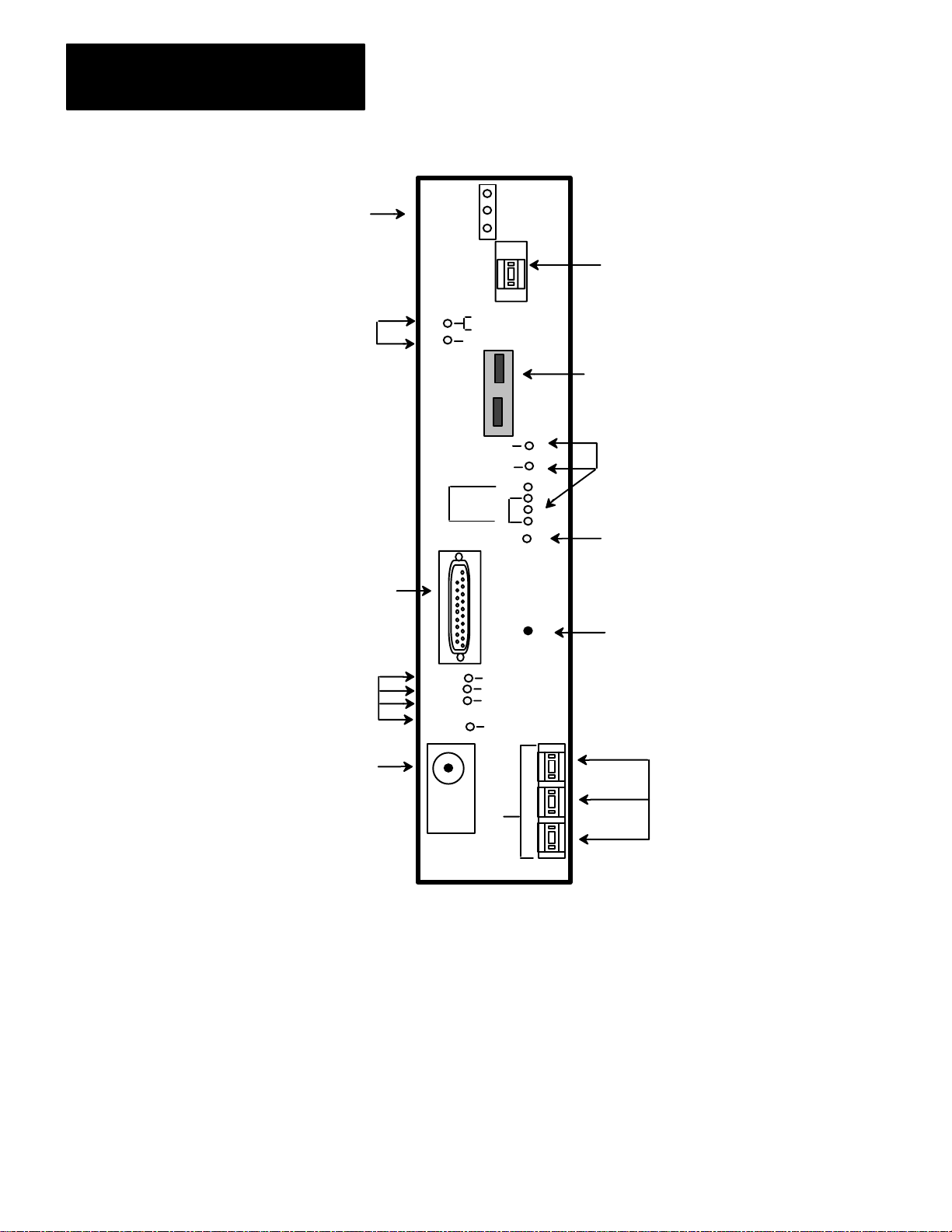
The 1779–KP3 operates in a single slot of an Allen–Bradley PLC–3
chassis. The front of the module (figure 1.1) contains:
LEDs that indicate the state of the module and the state of its
connection to the network
two ports for use in a backed–up system
a single thumbwheel switch that identifies the KP3 interface module
from other KP3 interface modules in the PLC–3 chassis
three thumbwheel switches that determine the node address
a single Data Highway II auxiliary access port that is reserved for
future use
The front panel of the 1779–KP3R Module is shown in Appendix A
(figure A.1) of this manual.
1-1
Page 8

Chapter 1
Overview
Figure 1.1
Panel of the KP3
Front
A Brief Look at Data Highway II
The following sections provide a brief overview of the Data Highway II
environment and related concepts you should be familiar with before
using the 1779–KP3 module.
Allen–Bradley Data Highway II is local area network designed for the
plant environment that allows your intelligent devices to communicate
with each other (figure 1.2).
Figure 1.2
Sample
Data Highway II Network
Computer
VAX
1779-KFM Interface
computer
1779-KP3
Interface
Data Highway II
1779-KFL Interface
PLC-3
10992-I
1-2
Page 9
Chapter 1
Overview
The Data Highway II network offers:
a transmission rate of one megabit per second
high immunity to noise
easy connection to control devices
This network is meant for time–critical operations where the status or
position of one device (e.g., PLC Programmable Controller, personal
computer, etc.) may affect another device, or an entire production line.
Data Highway II Cabling
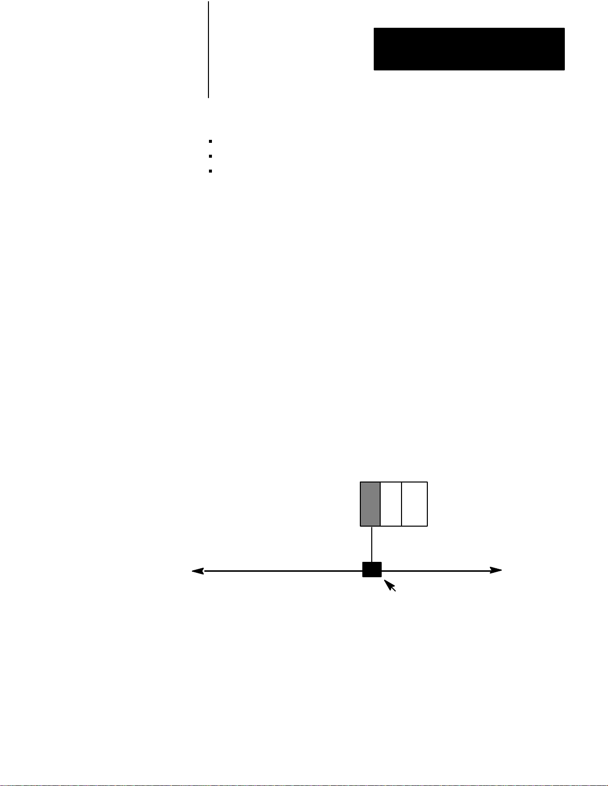
All communication on Data Highway II travels from one device to
another through the trunkline (figure 1.3). The trunkline varies in length
depending on the number of nodes and their location. Data Highway II
cabling is compatible with IEEE Specification 802.4 for single channel
phase–continuous FSK (frequency shift keying) systems.
You connect Allen–Bradley PLC Programmable Controllers to the Data
Highway II trunkline via an Allen–Bradley communications interface.
Data Highway II droplines connect the communication interfaces to the
trunkline. The mechanical connection between the dropline and the
trunkline is a local tap (figure 1.3).
Figure 1.3
KP3
The
Communications
Communication Interface
Interface on Data Highway II
1779-KP3
Allen-Bradley
PLC-3 Programmable
Controller
Dropline
Data Highway II Trunkline
local tap
10993-I
For information on planning and installing Data Highway II refer to the
Allen–Bradley Data Highway/Data Highway Plus/Data Highway II/Data
Highway 485 Cable Planning and Installation Manual, publication
1770–6.2.2.
1-3
Page 10
Chapter 1
Overview
You also have the option of running redundant cabling. You can order
Allen–Bradley Data Highway II interface modules with dual ports, which
allows you to install a back–up cable system. Thus providing more
security for your system if a failure occurs. See Chapter 2 for information
on redundant cabling.
Data Highway II Communication
A device and its communication interface make up a node on the Data
Highway II network (figure 1.4). The node sending a message is the
source node; the node receiving a message is the destination node.
Figure 1.4
Data Highway II Nodes
Sample
1779-KP3
PLC-3
Data Highway II
The source node
sends the message.
1779-KFM
Computer
The destination node
receives the message.
10994-I
Allen–Bradley Data Highway II has its own Data Highway II proprietary
communication protocol between the network communication interfaces.
All communication interface modules connected to this network ‘‘talk” to
each other using this protocol. For more information on Data Highway II
protocol, refer to Data Highway II Asynchronous–device Interface User’s
Manual (Publication 1779–6.5.1) or the Data Highway II
Synchronous–device Interface User’s Manual (Publication 1779–6.5.2).
1-4
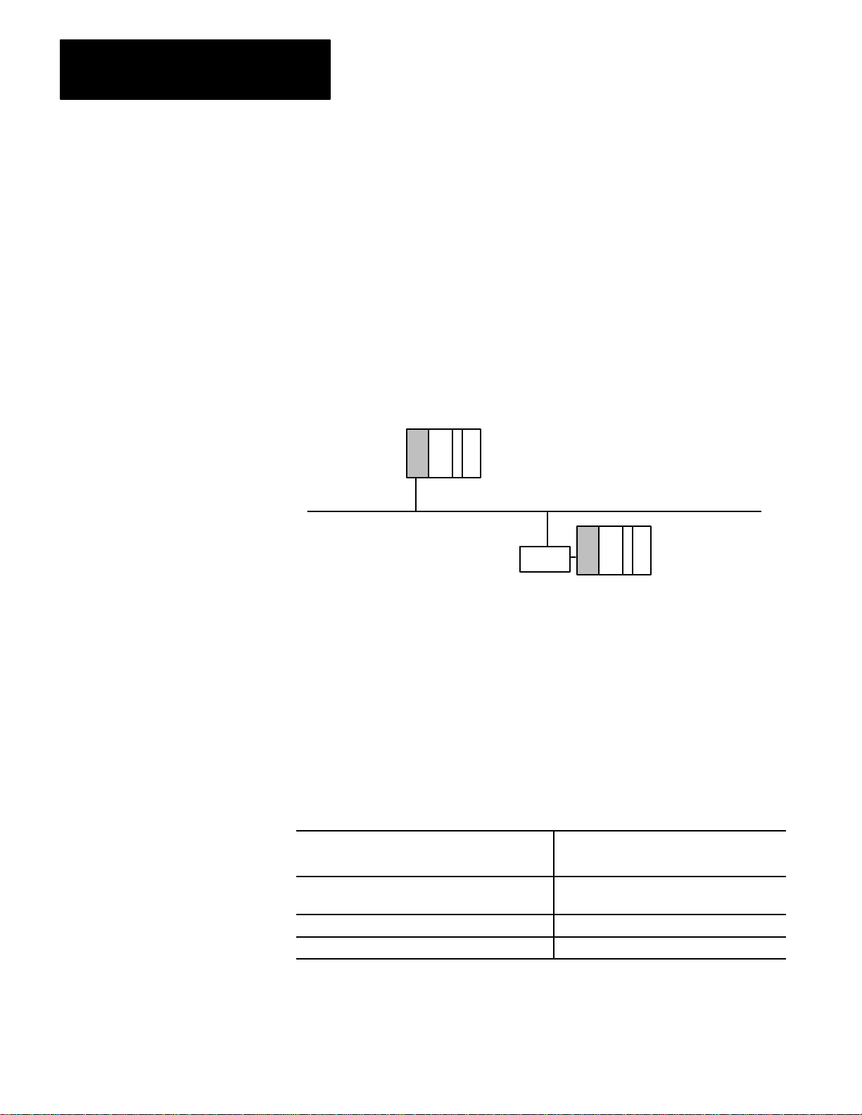
In a Data Highway II configuration, the nodes are situated along a
physical bus (figure 1.5). Communication is sent across the entire length
of the cable to the end nodes. Each node waits and ‘‘listens” for any
message addressed to it, accepts the message, and signals the original
sender that it has received the message.
Page 11
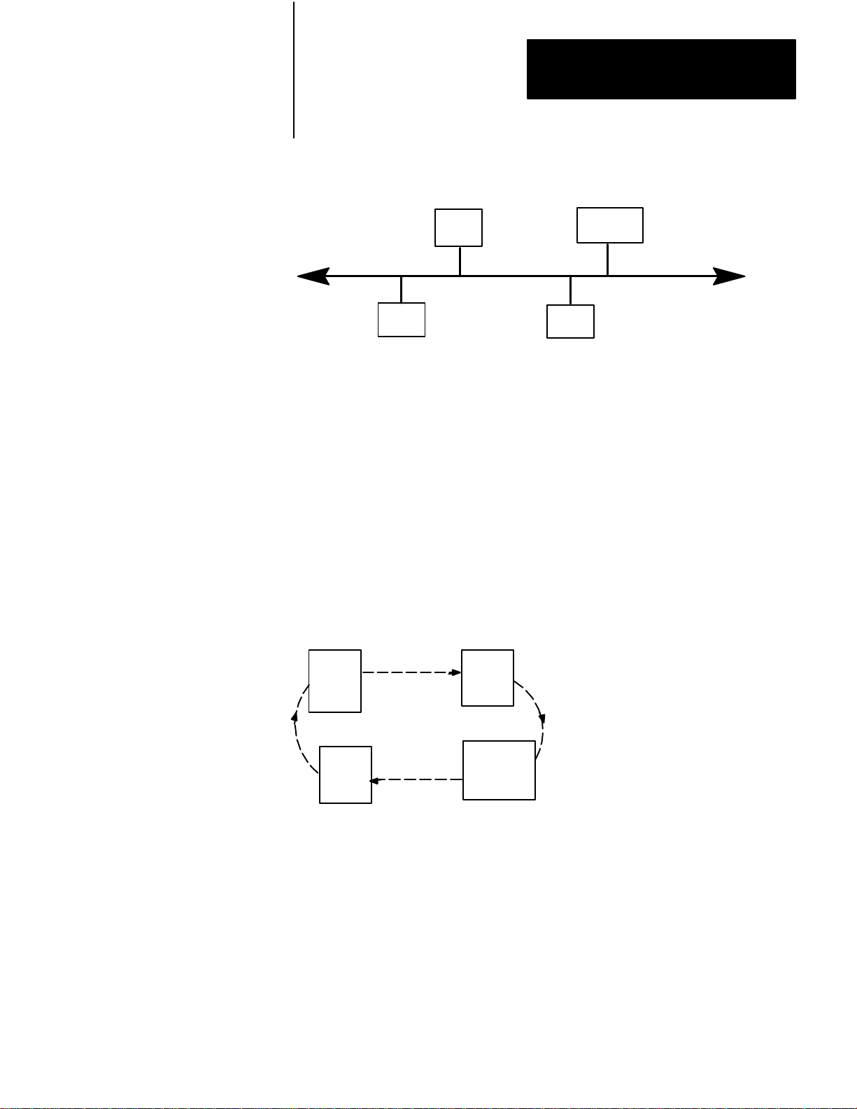
Figure 1.5
Highway II is a Physical Bus Network
Data
Chapter 1
Overview
Node
7
Node
16
10995-I
Node
1
Node
31
While the physical layout of the Data Highway II network is a bus, the
method of access to the network is a logical ring. Nodes are allowed to
communicate on the network while they posses the token. This token is
passed around the ring according to the nodes’ addresses on the Data
Highway II link. While a node possesses the token it is the master, and it
is the only node that can send commands out to the network. When it is
finished, the token passes to the node with the next highest address,
regardless of the node’s physical proximity to the previous node (figure
1.6).
Figure 1.6
Conceptual View of Data Highway II Logical Ring Communication
A
Node
1
Node
31
Node
7
Node
16
10996-I
When a node leaves the ring unexpectedly, the ring performs a recovery
procedure. The node with the next lowest node number attempts to pass
the token to the exiting node, but because it cannot, the ring must undergo
a recovery procedure to rebuild itself. When the message returns to the
inquiring node, the node can then pass the token to the node that has the
next highest number.
1-5
Page 12
Chapter 1
Overview
Data Highway II communication interfaces operate at different modes that
vary according the their relationship with the logical ring. The modes are:
In–ring mode, which is when the interface is a fully operational
member of the ring. It accepts messages, replies to them, and is ready
to send them.
Seeking–membership mode, which is when the interface is trying to
become a member of the ring so that it can send messages.
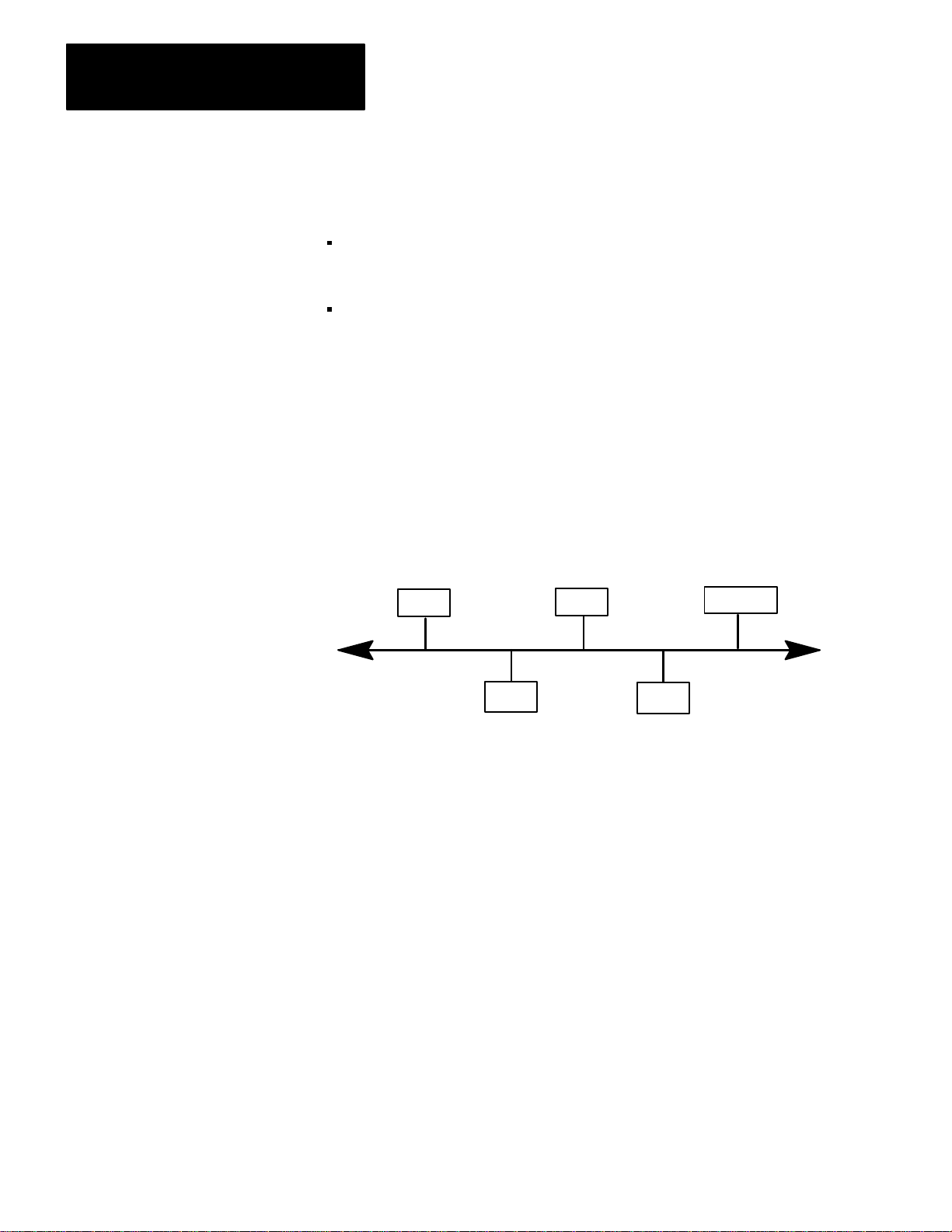
When we talk of communication on a Data Highway II network, it is
important to keep in mind the concept of a link. A Data Highway II link
is one section of trunkline, including nodes, that makes up a Data
Highway II network (figure 1.7); links are limited by length of the
trunkline. Nodes on different links are ‘‘off–link” with respect to each
other; nodes on the some link are ‘‘on–link” with respect to each other.
Figure 1.7
A
Data Highway II Link
Node
Node
Node Node
Node
10997-I
You can expand your Data Highway II network with the help of two
Allen–Bradley 1779–KP5 communication interface modules configured
as bridges. In this case, you would have two Data Highway II links
(figure 1.8).
1-6
Page 13
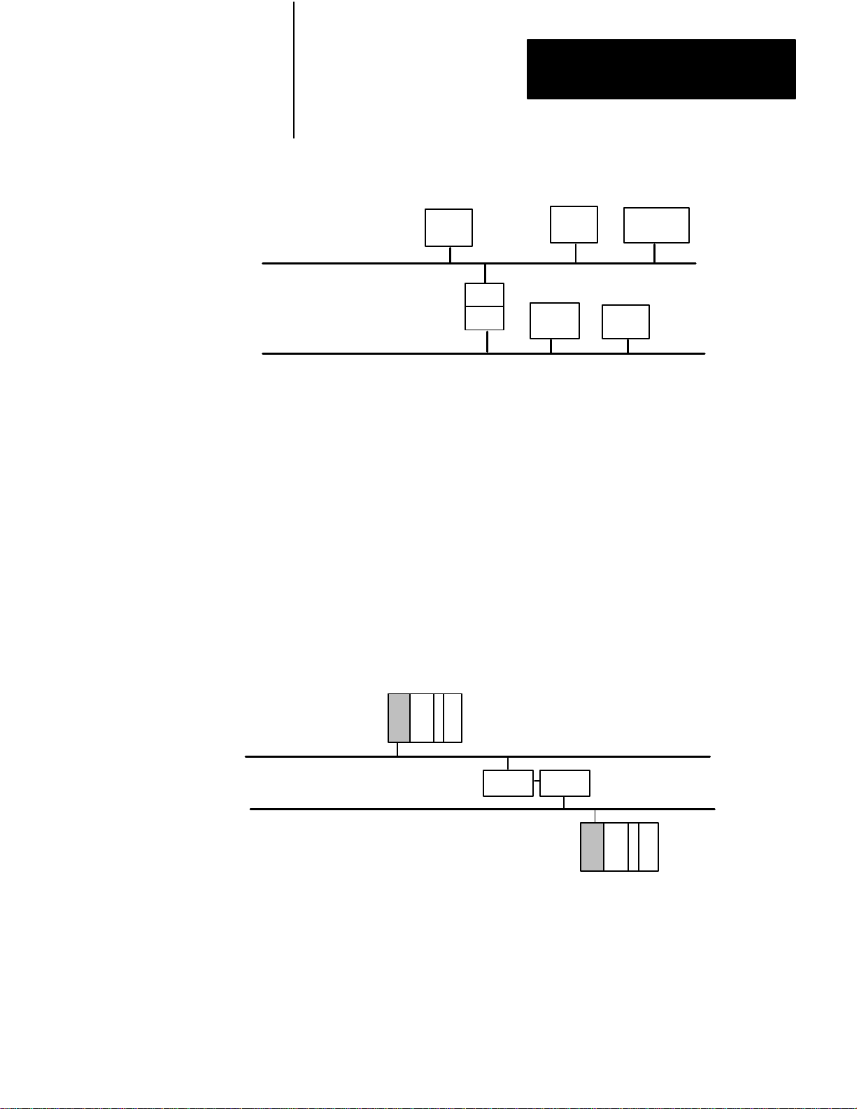
Figure 1.8
Data Highway II Links
Two
Chapter 1
Overview
Node
C
Node
Data Highway II Link 1
Data Highway II Link
Node
A
KP5
KP5
2
Node
B
Node
DE
Figure 1.8 shows two Data Highway II links. Notice that to ‘‘Node A”,
‘‘Node B” is on–link, and ‘‘Node D” is off–link. Data Highway II nodes
consider other nodes ‘‘off–link” if, to communicate with them, the Data
Highway II nodes have to cross a bridge.
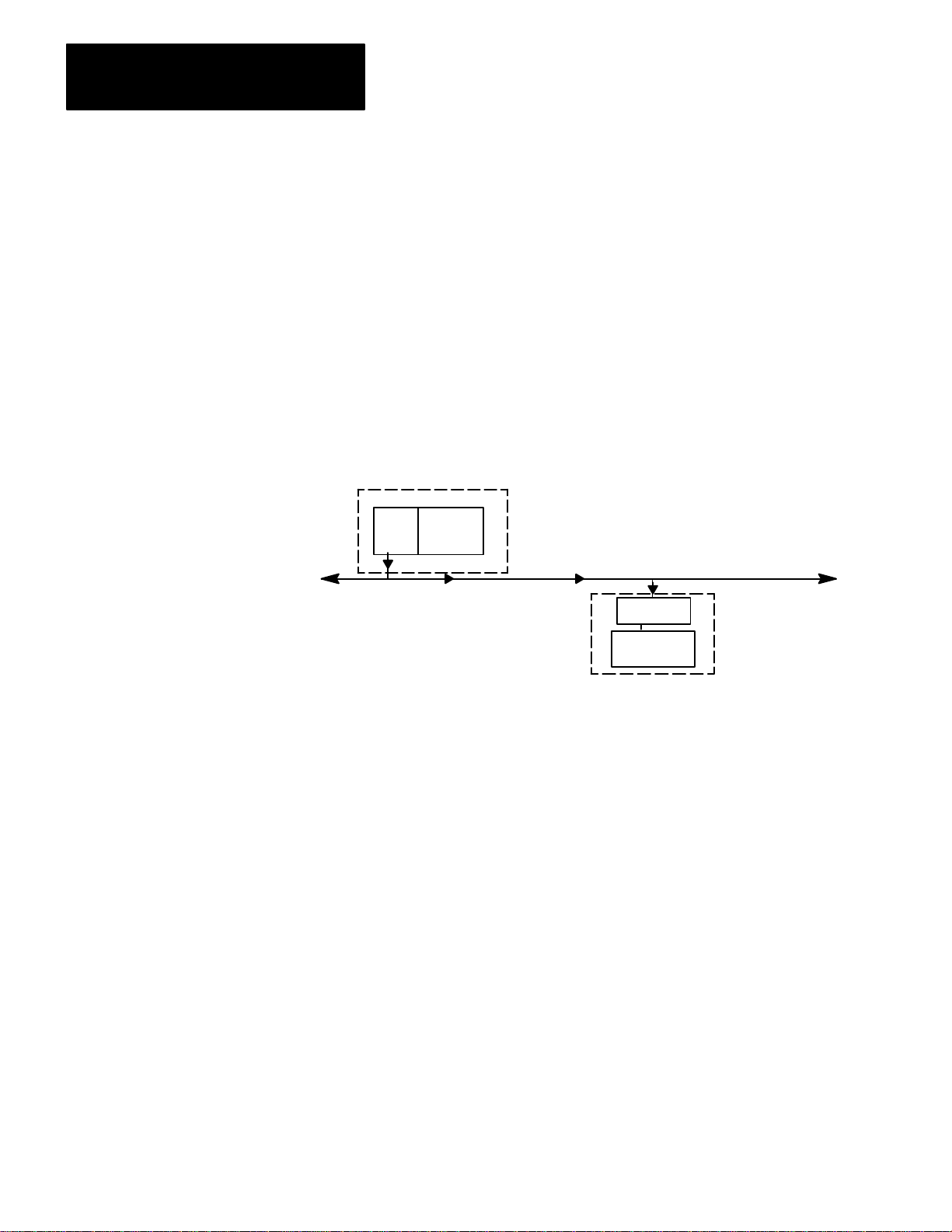
The link numbers become an important factor when you are addressing
messages. For example, if you have two Data Highway II networks
bridged together via two Allen–Bradley KP5 modules, the two links have
different link numbers (Figure 1.9). You use this link information inside
your message instruction (see Chapter 3 on Programming for more
information).
10998-I
Figure 1.9
Example
Data Highway II Link 1
Data Highway II Link 2
of T
Nodes on the same link (on–link), have the same link number; nodes on
different link (off–link), have different link numbers. Note that your local
link may always be specified as link zero; by default, the link you are
connected to is considered zero with respect to other local nodes you may
be communicating with.
wo Data Highway II Links
PLC-2
Link = 1
KP5
KP5
PLC-3
Link = 2
10999-I
1-7
Page 14
Chapter 1
Overview
You can also connect a Data Highway Plus subnetwork to your Data
Highway II network via one Allen–Bradley KP5 module. When you have
a Data Highway Plus sub–network attached to your Data Highway II
network, the nodes on Data Highway Plus are considered on–link to the
nodes on Data Highway II.
If you are sending a message instruction from a PLC–3 controller on Data
Highway II to a PLC–5
controller on Data Highway Plus, you would use
the same link number for both (figure 1.10).
Figure 1.10
Example
of Using Link Numbers When Addressing
PLC-3
Link = 0
KP5
Data Highway Plus Sub-link
Data Highway Link 0
PLC-5
Link = 0
11000-I
Note that in the this example, the PLC–5 controller considers the KP3
module a remote station and may refer to the KP3 as offlink. The PLC–5
controller cannot communicate to stations on another Data Highway II
link.
1-8
Note also that when we speak of KP3 communication on the Data
Highway II network, there are different types: communication initiated by
the KP3 and communication initiated via a computer. Refer to the
following table.
The KP3 has the ability to initiate simple
data transfers to:
another KP3 uploading and downloading of
a KP2 diagnostics
a PLC–5 controller (via a KP5)
You can initiate via a computer
(through a KFM or KFL module):
processor memory
station management
Page 15

Chapter 1
Overview
Allen-Bradley Communication Interface Modules
The following tables show the types of on–link and off–link connections
that are possible and the type of Allen–Bradley Communication Interface
Modules you need.
To connect this to a Data Highway
II Link:
an Allen–Bradley PLC–3 Controller 1779–KP3, –KP3R
an Allen–Bradley PLC–2 Controller 1779–KP2, –KP2R
a synchronous interface device
(RS–449 compatible)
an asynchronous interface device
(RS–232, –422 compatible)
another Data Highway II link two 1779–KP5 modules
a Data Highway Plus sub–network
link
1
The 1779–KP2 module does not allow communication to or from
other Data Highway II links.
To connect this to a Data Highway
Plus Sub–network Link:
You must use this
Allen–Bradley communication
interface:
1
1779–KFM, –KFMR
1779–KFL, –KFLR
configured as bridges
one 1779–KP5 Module (see
table below)
You must use this
Allen–Bradley communication
interface:
an Allen–Bradley PLC–3 Controller 1775–S5, –SR5
an Allen–Bradley PLC–2 Controller 1785–KA3
an Allen–Bradley PLC–5 Controller (built–in interface)
personal computer 1784–KT and 6001–F1E
Standard Driver Software or
1785–KE for RS–232
communication
1-9
Page 16
Chapter 1
Overview
operation LEDs
operation LEDs
PASS–
FAIL–
TEST–
KP3
BACKUP
A
BACKUP
B
1
G. IN–RING
Y. SEEKING
DUP ADDR
Thumbwheel switch that distin
guishes this KP3 from others in
the same chassis.
Two ports for providing optional
PLC-3 backups.
Auxiliary
Data Highway II port
(not used)
operation LEDs
Dropline
connection to the
network.
BACKUP MODE
A
C
T
NORMAL
I
V
I
T
Y
DATA
HWY II
PORT
ERROR
SAT
EXIT
COMP
DHII
AUX
ACCESS
EXIT REQUEST
PORT READY
SIG QUAL
TAP FAIL
EXT TAP CONFIG
L
M
I
S
N
D
K
A
D
D
R
E
S
S
operation LEDs
LED that indicates you have
stopped communication to the net
work.
Optional button you can use to stop
communication to the network.
1
1
Thumbwheel switches that
indicate this node's ad
dress
1-10
Page 17
Chapter
2
Installing the 1779-KP3 Communication Interface
Chapter Objectives
Printed Circuit Boards
This chapter contains the information you need to install your 1779–KP3
Communication Interface module. It covers the following topics:
printed circuit boards
setting the switches on the host board
setting thumbwheel switches
installing the KP3 into the PLC–3 chassis
using the LIST option to select additional KP3 parameters
connecting the KP3 to Data Highway II
connecting a PLC–3 to multiple Data Highway II links
how a PLC–3 backup system works on Data Highway II
installing a backup PLC–3 on Data Highway II
The 1779–KP3 interface is a single module that consists of two printed
circuit boards:
the host board
the media access controller (MAC) board
There are switches associated with each of these boards. Read the
following section before installing your module.
Set the Switches on the Host Board
Host Board
Mac Board
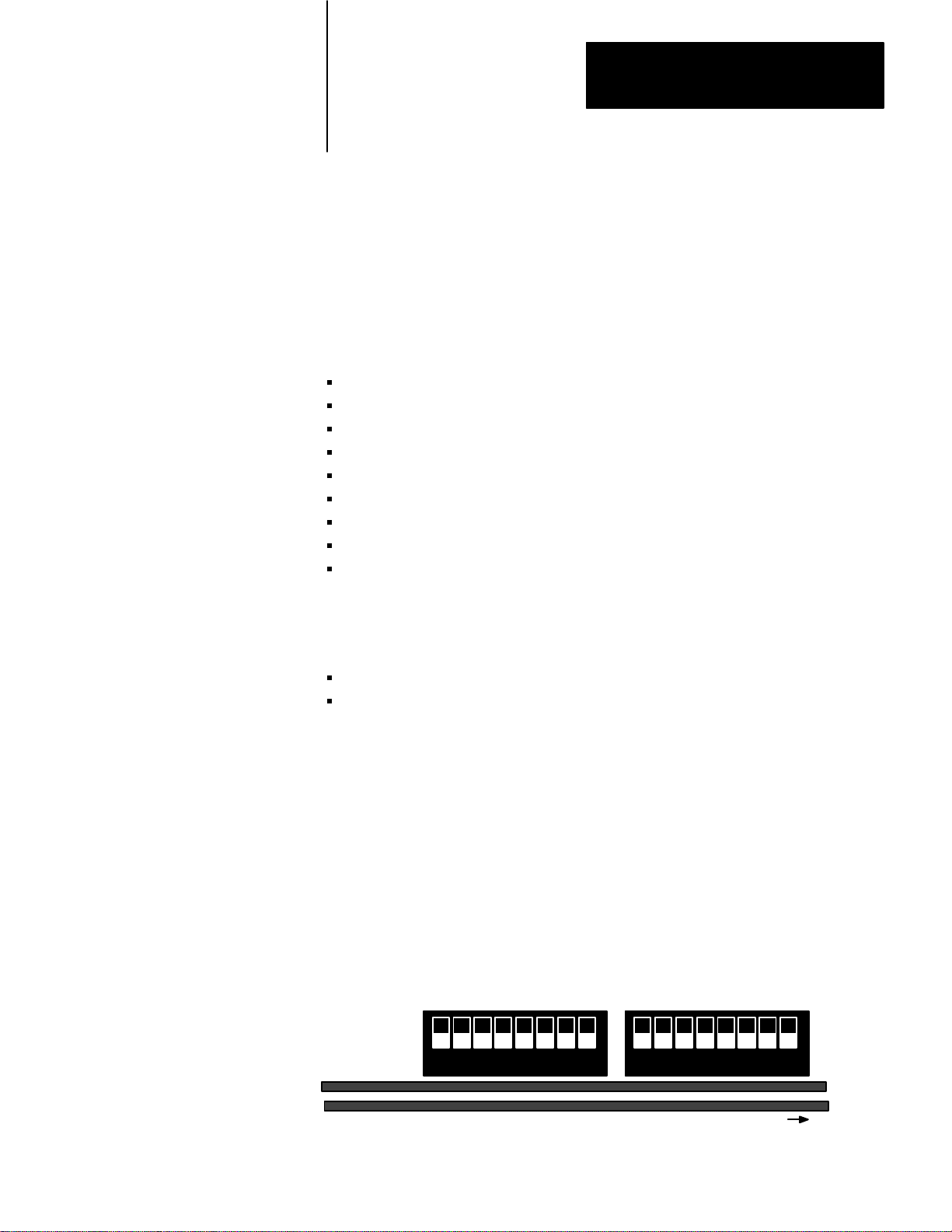
Before you install your KP3 interface, you must set the switches located
inside the module on the host board. There are two groups of switches:
Group 1 and 2. You can view them from the top of the module, looking
inside at the board (figure 2.1).
Figure 2.1
V
iew of Switches on the KP3 Module'
Top
Group 1 Group 2
1 2 3 4 5 6 7 8
s Host Board
1 2 3 4 5 6 7 8
Front of Module
11001-I
21
Page 18

Chapter 2
Installing the 1779-KP3
Communication Interface
You set these switches to select module options and protection/privilege
options. Keep in mind that when the switch is down, it is on (closed);
when it is up, it is off (open). Figure 2.2 shows an example setting; the
white areas correspond to the movable part within each switch.
Figure 2.2
Clarifying
the Switch Positions
Up = OFF
Down = ON
1 2 3 4 5 6 7 8
Switch 3 is OFF, the rest are ON.
11002-I
Setting Switches in Group 1
In Group 1, switches 1 and 2 determine the actions of the KP3 and PLC–3
controller if either should fault for some reason. Switches 3 and 4 are
used if you are using your KP3 in a backup system (see Installing Backup
PLC–3s on Data Highway II later in this chapter for more information).
Switches 5 through 8 are reserved for future Allen–Bradley applications
and you should not set them. Table 2.A lists the Group 1 switches and the
setting indications.
22
Page 19

Table 2.A
Group1
Chapter 2
Installing the 1779-KP3
Communication Interface
Switch Settings
If: Set
switch
number:
you want the KP3 to fault and disable its Data HIghway II
port if the PLC-3 faults
you want the KP3 Data Highway II port to remain
enabled if the PLC-3 faults
you want the PLC-3 to fault if the KP3 faults
you want the PLC-3 to remain enabled if the KP3 faults
the KP3 is part of a backup system
Important:
your primary and backup KP3s to the same link address.
When the backup is in ef
link address of the backup KP3 as one number greater
than the node thumbwheel. If switch 3 is OFF
switch 1
the PLC-3, not the KP3, is in a backup system
Important:
is in a backup PLC-3. It will not react to a switch over
If you select OFF
must
be OFF also.
The KP3 will keep the node address when it
, set the thumbwheels of
fect, Data Highway II sees the
, then
.
To:
1 OFF
ON
2 OFF
ON
3 OFF
ON
you want the backup connector on the KP3 enabled
you want the backup connector on the KP3 disabled
Important:
Do not touch switches 5,6,7, and 8; they are reserved for future use.
4 OFF
ON
Setting Switches in Group 2
The Group 2 switches deal with programming options. Table 2.B lists the
Group 2 switches and the setting indications. Switches 1, 2, 3, 7 and 8
are reserved for future Allen–Bradley applications and you should not set
them.
23
Page 20

Chapter 2
Installing the 1779-KP3
Communication Interface
Table 2.B
2 Switch Settings
Group
If: Set
switch
number:
you want the KP3 to accept write commands to the program
areas of the PLC-3 memory
keyswitch position
you want the PLC-3 keyswitch position checked to
determine if write commands are allowed to the program
areas of PLC-3 memory
you want the KP3 to accept write commands to the data
table areas of the PLC-3 memory
keyswitch position
the PLC-3 keyswitch position checked to determine if write
commands are allowed to the data table areas of PLC-3
memory
you want the KP3 to accept write commands to the status
areas of memory
position
you want the PLC-3 keyswitch position checked to
determine if write commands are allowed to the status areas
of PLC-3 memory
, regardless of the PLC-3 keyswitch
, regardless of the PLC-3
, regardless of the PLC-3
To:
4 ON
OFF
5 ON
OFF
6 ON
OFF
24
Important:
Do not touch switches 1, 2, and 3; they are reserved for future use.
The MAC Board Switch Your Module May Have
If your 1779–KP3 Interface has a series A MAC board, you will also have
a 2–switch group on the MAC board. You can view it from the top of the
module looking down at the MAC board. Figure 2.3 shows the location
of this switch in relation to the host board switches; this is a side view of
this group. Note that this switch does not exist on redundant modules
(1779–KP3R) or 1779–KP3 modules with series B MAC boards.
Figure 2.3
The
MAC Board Switch Group
Side view of 2-switch Group
Mac Board
Front of Module
Host Board
1 2 3 4 5 6 7 8
1 2 3 4 5 6 7 8
11003-I
Page 21
Chapter 2
Installing the 1779-KP3
Communication Interface
Verify that both of the switches in this group are set to OFF (open).
Figure 2.4 shows the position they should remain in.
Figure 2.4
Position of the MAC Switches (Front V
Correct
OFF = up
iew)
Set the Thumbwheel Switches
1 2
Mac Board
11004-I
Important: Do not to change these switch settings if you have them. In
the later (series B) versions of the KP3 MAC board, changes were made
to the hardware, making the need for this MAC switch unnecessary.
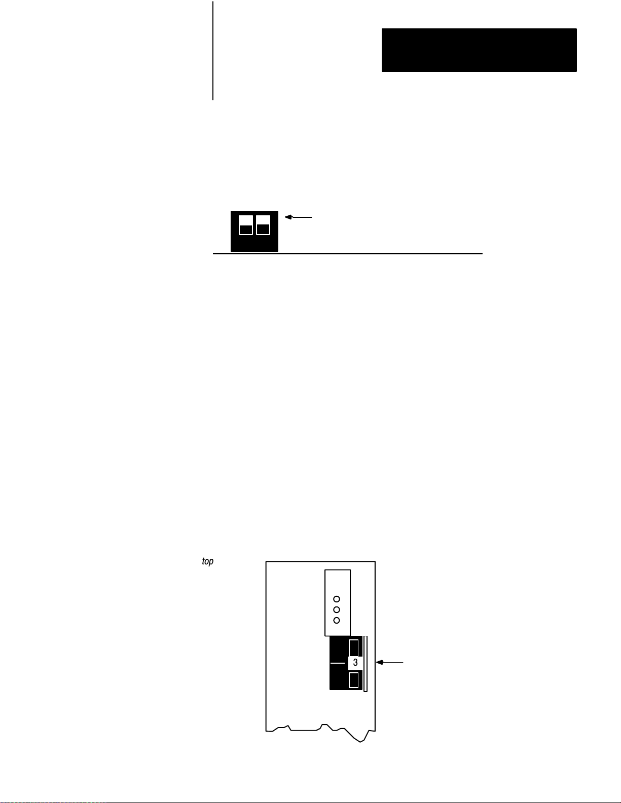
There are four thumbwheel switches on the KP3’s front panel. Use the
one at the top of the module (figure 2.5) to set the KP3’s module number.
This number distinguishes it from other KP3 modules in the chassis. You
should start with the number 1 and as you add KP3 modules to the
chassis, go to the next highest consecutive number.
Important: If you are using the KP3 in a backup system make sure the
module numbers in the primary and backup KP3s are the same.
Figure 2.5
The
Thumbwheel Switch to Set the KP3 Module Number
top of module
PASS
FAIL
TEST
KP3
_
_
_
3
Thumbwheel Switch
25
Page 22

Chapter 2
Installing the 1779-KP3
Communication Interface
Use the three thumbwheel switches at the bottom of the front panel to set
the Data Highway II node address for the KP3. You can use from 1 to
376 octal. For example, to select node address 123, set the thumbwheels
as shown in figure 2.6.
Figure 2.6
Example
Thumbwheel Switch Setting for the Node Address
L
I
N
K
A
D
D
R
E
S
S
1
2
3
Most significant digit
Least significant digit
Install the KP3 Module
Once you have set the switches on the host board and the thumbwheels on
the front panel, you are ready to install the KP3 module into the PLC–3
chassis. The KP3 is a single–slot module that you can place next to any
other PLC–3 module in the chassis.
Important: We assume you have a Data Highway II network up and
running, and a drop line cable ready to attach to the module. If you need
cabling information, refer to the Allen–Bradley Data Highway/Data
Highway Plus/Data Highway II/DH–485 Cable Installation Manual
(publication 1770–6.2.2).
Follow the procedure below to install your KP3 module into your
Allen–Bradley PLC–3 chassis.
1. Remove power from the PLC–3 chassis.
2. Lift the interlock bar that is inside the chassis and secure it to the
brackets that are mounted at the top of the chassis (your chassis may
have a hinged interlock bar attached to the top that flips up away
from the front).
26
Page 23

Chapter 2
Installing the 1779-KP3
Communication Interface
3. Slide the module into the chassis slot, making sure it slides along the
grove at the bottom of the slot. Press firmly until you feel it snap
into the backplane.
4. Pull the interlock bar back into place.
5. Restore power to the chassis.
6. Use LIST to select additional KP3 options (see following section).
Use the LIST Option to Select Additional KP3 Parameters
After you install the KP3 into the chassis, use the LIST option to select
additional operational KP3 parameters. You access the LIST option
through an Allen–Bradley PLC–3 Industrial Terminal (1770–T4) which
has the ability to communicate directly with your Allen–Bradley PLC–3.
Refer to the PLC–3 Controller Installation and Operations manual,
publication 1775–6.7.1, for instructions on accessing the LIST function.
You can also access LIST through Allen–Bradley 6200 Programming
Software (see the PLC–3 Programming Software User Manual for
information, publication 6200–6.5.3).
The following procedure shows you how to use LIST.
1. Connect a T4 Industrial Terminal (1770–T4) to the PLC–3 controller.
2. Turn the T4 terminal ON.
3. Press the shift key and then the mode key. You receive a mode of
operation menu:
SELECT MODE OF OPERATION
1 = PLC3 TERMINAL
2 = ALPHANUMERIC TERMINAL
4. Press 1. You receive a blank screen with a $ sign prompt at the
bottom.
11005-I
27
Page 24

Chapter 2
Installing the 1779-KP3
Communication Interface
5. Enter the LIST function at the $ prompt by pressing the shift key and
then the list key. You receive the SYSTEM–MODE menu:
SYSTEM-MODE SCREEN
1. TEST MONITOR
2. RUN MONITOR
3. *PROGRAM LOAD
4. REMOTE ENABLE
5. SYSTEM STATUS
6. MODULE STATUS
ENTER NEXT>
11006-I
6. Select the MODULE STATUS option by typing 6 <enter>.
The MODULES menu appears, which lists all of the modules in the
PLC–3 system by catalog number, including the KP3.
7. Select 1779–KP3 from the MODULES menu by typing the number
next to it and pressing <enter>. You will receive a DATA HWY II
INTERFACE menu:
Data Hwy II Interface
KP3 1, Node 111
Chassis 0, Slot 6
1 Message Timeouts
2 Token Hold Factor
3 Set Node Mode
4 Input File List
Enter Next>
The menu above shows the 4 different options you have to choose from
within the first menu. When you choose any of these options, you will
receive another menu. The following sections describes each of these
options and the sub–menu options associated with them.
28
Page 25

Chapter 2
Installing the 1779-KP3
Communication Interface
The Message Time-outs Menu
When you choose option 1, you receive the Message Time-outs menu:
KP3 1, MESSAGE TIMEOUTS
1 TIME CRITICAL TIMEOUT
2 SUPERVISORY TIMEOUT
3 THIRD-PARTY TIMEOUT
ENTER NEXT >
This
option:
1
2
3
1
The
default value appears the first time you use this menu.
allows
you to:
set the time-out for
time-critical messages.
set the time-out for
supervisory messages.
Use to send information
that in not time critical,
such as reports.
(Not available with this release.)
Minimum value:
0.01 seconds 10.00 seconds .50 seconds
0.01 seconds 650.00 seconds 1.00 seconds
Maximum
Value:
Default
Value
1
:
Important: You must enter the time–out value for time–critical and
supervisory messages with a decimal point and two digits to the right of it.
The Token Hold Factor Menu
When you select option 2 from the Data Highway Interface menu, you
receive the Token Hold Factor menu:
KP3 1, TOKEN HOLD FACTOR
FACTOR = 1
ENTER FACT
OR >
This menu allows you to set and display the amount of time a node is
allowed to possess the token before passing it to the next node. The menu
allows you to change the link–layer token hold factor.
You can enter a number from 1 to 256, the default factor is 1. With a
factor of 1, the node will hold the token for the standard hold time. The
29
Page 26

Chapter 2
Installing the 1779-KP3
Communication Interface
token hold time is multiplied by the number you enter. For example, if
you enter 2, the token hold time will double. You may want to increase
the token hold time at the node if, for example, that node typically has
more messages to send than other nodes.
The Set Node Mode Menu
When you select option 3 from the Data Highway II Interface menu, you
receive the Set Node Mode menu. This menu allows you to change the
mode of the KP3:
KP3 1, SET NODE MODE
1 INRING
2 ONLINE
3 OFFLINE
The following table shows what each value means.
If
you set the mode to:
INRING
ONLINE
OFFLINE
Then:
the KP3 is fully operational.
the KP3 allows requests for immediate data and `
writes with no reply". The KP3 will not initiate any messages, nor
reply to any
the KP3 will not initiate or respond to any messages.
.
`time-critical
The Input File List Menu
When you select option 4 from the Data Highway II Interface menu, you
receive the Input File List menu:
KP3 1, INPUT FILE LIST
ENTER STATION AND INPUT FILE >
Use this to tell the KP3 which input file to read data from or write data to
when it receives a message from a device using PLC–2–style addressing
(e.g., a 1779–KP2, –KFL, or, –KFM interface module or another KP3
module).
210
Page 27

Chapter 2
Installing the 1779-KP3
Communication Interface
When the KP3 receives a message containing PLC–2–style addressing, it
searches the input file list and reads to or writes from the input file
specified for the node that sent the message. If the sending node is not in
the list, the KP3 uses the octal address of the source node as the decimal
input–file number.
You can enter any given node only once into the input file list, for
example:
KP3 1, INPUT FILE LIST
ENTER STATION AND INPUT FILE > :5 2
The example above sets up node ‘‘5” to read from or write to input file
‘‘2”.
If the station is on another Data Highway II link, specify the link number
before the : sign. If the station is not user 1 (e.g., channel 2 of a
1779–KFL module), put a period (.) and after the node number, and
followed by the user number.
To delete an input file entry, enter the node, followed by ‘‘/D”, for
example:
KP3 1, INPUT FILE LIST
ENTER STATION AND INPUT FILE > :5 /D
211
Page 28
Chapter 2
Installing the 1779-KP3
Communication Interface
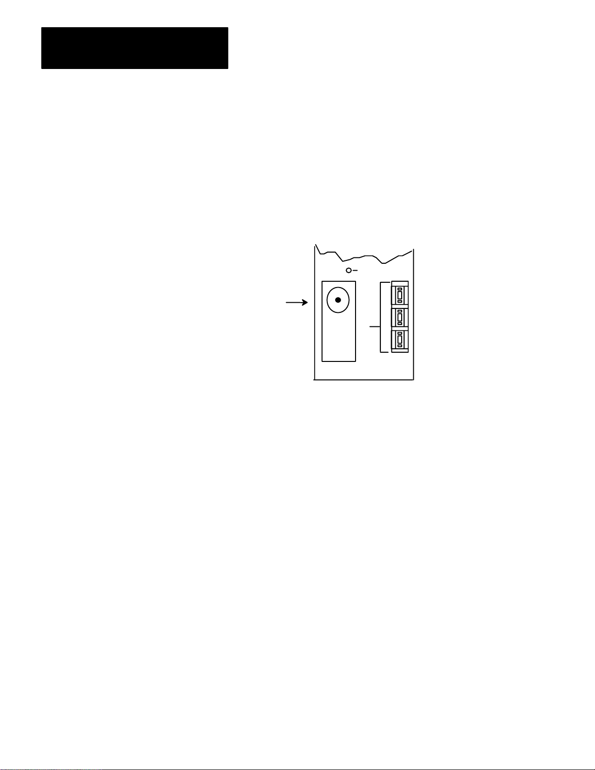
Connecting the KP3 to Data Highway II
Once you have installed and configured the KP3 module, follow the
procedure below to connect it to the highway.
Important: If you are connecting a backup PLC–3 system to Data
Highway II, remember that you must run at least 30 feet of trunkline cable
between droplines to the primary and backup KP3 modules.
1. Locate the Data Highway II Port on the KP3 front panel.
EXT TAP CONFIG
L
M
Dropline
connection to the
network.
DATA
HWY II
PORT
KP3
I
S
N
D
K
A
D
D
R
E
S
Front Panel
S
1
1
Connecting a PLC-3 to Multiple Data Highway II Links
2. Connect a Data Highway II dropline to the connector by sliding the
dropline connector over the port and twisting the collar clockwise.
If you have a KP3R module, repeat steps 1 and 2 for the port labeled Data
Highway II PORT 2.
You can connect a PLC–3 to multiple Data Highway II links. The PLC–3
requires one KP3 for each Data Highway II link it communicates over.
Follow the procedure below to connect a PLC–3 to multiple Data
Highway II links.
1. Install one KP3 in the PLC–3 chassis for each link the PLC–3 will
communicate over.
2. Select a unique module number on the thumbwheel of each KP3 in
the same chassis.
3. Connect each KP3 module to separate links via separate droplines.
212
Page 29

Chapter 2
Installing the 1779-KP3
Communication Interface
You can assign the same node address to more than one KP3 in the same
PLC–3 chassis as long as the KP3s are communicating over different
links.
Important: You are not required to connect these separate links by Data
Highway II bridges.
How a PLC-3 Backup System Works on Data Highway II
When we talk about a ‘‘backup” system, we a talking about having a
primary PLC–3 on the network and a backup PLC–3. The pairs need to
be connected in such a way that one ‘‘takes over” if something should
happen to the other (switchover).
When you configure a backup system on Data Highway II, the primary
and backup KP3s must have their thumbwheels set to the same link
address. As far as the Data Highway II is concerned, however, the backup
KP3 will assume a link address that is one number higher than the
primary KP3.
For example, if you have set the link address on both KP3s to 176 octal,
Data Highway II will list the backup KP3 as having a link address of 177
octal. This enables you to send messages to the backup KP3 from other
nodes on the link. When a switchover occurs, the backup KP3 will
become node 176 as far as the link is concerned. Node 177, the link
address of the backup KP3, will then disappear from the link.
What You Should to Monitor Possible Switchover
At the time a switchover happens and the backup KP3 becomes the
primary KP3, the new primary KP3 has no way of knowing which
messages were initiated by the former primary KP3. For this reason, you
should monitor the run/backup bit (data table status section, file 0, word
3, bit 7) in your PLC–3 ladder diagram program. In the event of a
switchover, set the done bit of each message instruction. This allows any
message being initiated during a switchover to be sent again.
Important: Alert the proper personnel when a switchover occurs. One
way you can provide this indication is by having your program monitor
the run/backup bit, and turn on alarms or lights when the status changes
from backup to run. This bit is set in the primary processor and reset in
the backup processor.
213
Page 30

Chapter 2
Installing the 1779-KP3
Communication Interface
Installing a Back-up PLC-3 System on Data Highway II
You can set up a PLC–3 backup system in three ways, using an:
I/O Scanner–programmer Interface Module (1775–S4A), a PLC–3 I/O
Scanner Communication Adapter Module (1775–S5) or a Memory
Communication Module (1775–MX) without the KP3
S4A, S5, or MX with the KP3
S4A or S5 with an MX, and the KP3
The following sections discuss each of these possibilities.
Using an S4A, S5 or MX Without the KP3
You can connect the primary and backup PLC–3s by connecting the
1775–S4A (1775–S5, or 1775–MX) in each PLC–3 processor (figure 2.7).
Figure 2.7
Backup
Cabling W
Primary PLC-3
ithout the KP3
S4A KP3
Backup
Backup PLC-3
S4A KP3
Backup
214
11007-I
This method is recommended when the application process requires that
the Data Highway II switchover of communication happens after the
backup PLC–3 has taken control of the live I/O. Use this method when
the KP3 is involved in primarily supervisory transactions. This method is
fully explained in the PLC–3 Backup Concepts Manual (publication
1775–6.3.1).
You can also directly connect the S5 or MX modules in the primary and
backup PLC–3s.
Using the S4A, S5, or MX With the KP3
You can connect the S4A (S5 or MX) module to the KP3 module in both
the primary and backup PLC–3s. Then connect the KP3 in the primary
PLC–3 to the KP3 in the backup PLC–3 (figure 2.8).
Page 31

Figure 2.8
Cabling W
Backup
Chapter 2
Installing the 1779-KP3
Communication Interface
ith the KP3
Primary PLC-3
S4A KP3
Backup Backup
Backup
Important: Because of the various options for this cable, refer to
the backup cable configuration information in the PLC–3 Backup
Concepts Manual (publication 1775–6.3.1).
1775-CBB
Cable
A
B
1775-CBB or
1779-CBC Cable
KP3
A
Backup
B
Backup PLC-3
S4A
11008-I
This method provides faster switchover of communications between
primary and backup PLC–3s. Use this method when:
the application process requires that switchover occur as fast as
possible and that the backup KP3 switches to primary operation without
waiting for the backup PLC–3 to take control of the I/O.
the KP3 module is involved in many time–critical transactions.
you plan to send time–critical messages to the PLC–3 processor.
Because of the various options for this cable, refer to the backup cable
configuration information in the PLC–3 Backup Concepts Manual
(publication 1775–6.3.1).
Important: The 1775–CBB cable assembly has one end that you can
configure. When making cables, note the location of the locking
connector tab on the module to be certain of the correct connector
position. The S4A and MX modules both have the locking tab on the
opposite side in comparison to the KP3. The connection between the S4A
and the KP3 module is a straight through cable in relation to pin 1 of the
connectors (figure 2.9).
The 1779–CBC cable is shipped assembled at both ends.
215
Page 32

Chapter 2
Installing the 1779-KP3
Communication Interface
Figure 2.9
Cabling Using the SA4 and KP3 Modules in Detail
Backup
1775-CBB
1779-CBC Cable
or
S4A
Backup
KP3
Backup A
Backup B
Backup A
Backup B
1775-CBB Cable
Using an S4A or S5, an MX, and a KP3
KP3 S4A
Pin 1
1775-CBB or
1779-CBC Cable
11009-I
You can provide backup PLC–3s by connecting the S4A (or S5) module
to the KP3 module in both the primary and backup PLC–3s. Then
connect each KP3 to the MX modules. Then connect the primary MX
module to the MX in the backup (figure 2.10). This method provides
faster switchover of communications between the primary and backup
PLC–3 processors.
216
Page 33

Chapter 2
Installing the 1779-KP3
Communication Interface
Figure 2.10
an S4A, MX, and a KP3 for Running Backup Cabling
Using
1775-CM Cable (2 feet)
1775-CBB or
1779-CBC Cable
S4A
Backup
1775-CM Cable (2 feet)
Backup A
Backup B
Pin 1
KP3
Pin 1
MX MX
Pin 1
XMT
REC
1775-CM Cable Assembly
Pin 1
XMT
REC
KP3 S4A
Backup A
Pin 1
Backup B
Pin 1
1775-CBB or
1779-CBC Cable
Backup
Pin
1
11010-I
Important: The 1775–CBB cable assembly has one end that you can
configure. When making cables, note the location of the locking
connector tab on the module to be certain of the correct connector
position. The S4A and MX modules both have the locking tab on the
opposite side in comparison to the KP3. The connection between the S4A
and the KP3 module is a straight through cable in relation to pin 1 of the
connectors.
The 1779–CBC cable is shipped assembled at both ends.
The 1775–CM cable assembly includes four cables: two for
transmit/receive connections for the MX modules, and two interconnect
cables that you can use to connect the KP3 modules to the MX modules.
217
Page 34

Chapter 2
Installing the 1779-KP3
Communication Interface
Backup Cable Wiring for Linking a KP3 to an S4A, S5, or MX
The following diagram shows the recommended wiring for a backup cable
linking a KP3 module to an S4A or MX module.
Figure 2.11
Recommended
W
iring for Backup Cable Linking a KP3 to an S4A, S5, or MX Module
Creating a Backup System for
a PLC-3 Communicating on
Multiple Links
S4A
Pin 1
1
2
3
4
1
2
3
4
11011-I
If the PLC–3 processor is communicating on more than one link, connect
the KP3s in each chassis by routing a 1775–CBB cable from backup port
A on the first KP3 to backup port B on the next KP3 (figure 2.12).
Figure 2.12
Backup
Cable W
KP3
Backup A
ith More Than One Data Highway II Link
KP3 KP3
Backup A
1775-CBB or
1779-CBC Cable
Backup
KP3 S4A
A
Backup A
Pin
1
1775-CBB
1779-CBC Cable
or
218
Pin 1
Backup B
Pin 1
Pin 1
Backup B
Pin 1
Pin 1
Backup
Pin 1
B
Important: Because of the various options for this cable, refer to the
backup cable configuration information in the PLC–3 Backup
Concepts Manual (publication 1775–6.3.1).
Pin 1
Backup B
Pin 1
1775-CBB or
1779-CBC Cable
11012-I
Page 35

Chapter 2
Installing the 1779-KP3
Communication Interface
Important: The 1775–CBB cable assembly has one end that you can
configure. When making cables, note the location of the locking
connector tab on the module to be certain of the correct connector
position. The S4A and MX modules both have the locking tab on the
opposite side in comparison to the KP3. The connection between the S4A
and the KP3 module is a straight through cable in relation to pin 1 of the
connectors.
The 1779–CBC cable is shipped assembled at both ends.
219
Page 36

Programming
Chapter
3
Chapter Objectives
Transferring Data
This chapter contains information on programming your PLC–3 to
communicate on the Data Highway II network. We will discuss the
information you place in a PLC–3 message send instruction. The PLC–3
Message Send instruction itself is covered in greater detail in the PLC–3
Programmable Controller Programming Manual (publication 1775–6.4.1).
This chapter covers the following topics:
transferring data
the TO and FROM qualifiers
the format for addressing Data Highway II nodes
the format for addressing the memory in Allen–Bradley PLC
Programmable Controllers
The terms onlink and offlink are used extensively throughout this chapter
and we assume that you are familiar with them. For an overview of these
concepts, refer to Chapter 1.
This section covers the commands and qualifiers you can use to transfer
data using the KP3 module.
The commands you can use are listed in the table below:
Command:Use
MOVE
TMOVE
A qualifier is a word used to specify the details of the data transfer. The
qualifiers you can use with the commands above are listed in the
following table.
to:
tell the KP3 to move a bit, a word, or a contiguous block of words. This is usually
used to move data to or from a remote node on Data Highway II, but you can
also use it to move data to and from a node on Data Highway Plus or within the
PLC-3.
tell the KP3 to move a bit, a word, or a contiguous block of words. This can be
used to transfer data to and from an onlink Data Highway II node. It is usually
used to transfer small amounts of time-critical data in a small amount of time.
31
Page 37

Chapter 3
Programming
Qualifier: Use:
TO to
FROM
NOSTATUS only
specify the destination of the data transfer
either command and it must be followed an address (which must include a
data table address and can include a remote node address). You can
abbreviate as T
to specify where you want to transfer data from. You can use FROM with either com
mand, but if omitted, you must replace it with an integer constant. FROM is always
followed by an address (which must include a data table address and can include a
remote node address). You can abbreviate as F.
with a TMOVE command designed to transfer data to some remote
node. Use when error reporting is not necessary and you want to eliminate
the time spent receiving information about the success or failure of the
command (see the TMOVE Command section for usage). You can
abbreviate as N.
.
. Y
ou must use T
O when using
You can specify an integer constant in a MOVE or TMOVE command in
place of the FROM qualifier and its associated address. The correct
format for an integer constant is:
#digit
Where digit is either the integer 0 or 1. You can use integer constants only
when moving bits.
I0:10
You enter the commands and qualifiers in a command line to create a
PLC–3 message instruction. The following is an example of a typical
command line containing a command and qualifiers:
MOVE FROM 1:50$B222:2 TO $B111:1, 1000
Figure 3.1 shows an example message instruction display of the data from
the command above.
Figure 3.1
Example
02
of a Message Instruction Display
MSG
MESSAGE TYPE 1
CTL=FB010:0000= XXX
CH:E2.9.1
MOVE FROM 1:50$B222:2
TO $B111:1,1000
STAT
( EN )
12
STAT
( DN )
15
STAT
( ER )
13
11013-I
32
Page 38

Chapter 3
Programming
Refer to the PLC–3 Programming manual (publication 1775–6.4.1) for
more information on the PLC–3 Message Send Instruction. The
following sections cover each command in more detail and give examples
for usage. In the syntax examples that follow, we use angle brackets < >
to indicate information that you will enter that is specific to your
application. For example <address> in a command line indicates where
you would add an address specific to your application.
Using the MOVE Command to Transfer Data
Use the MOVE command to instruct the KP3 to transfer a:
bit
word
contiguous block of information
Usually this data is transferred to or from a remote node on Data Highway
II. You can, however, use the MOVE command to transfer data within the
local PLC–3 simply by omitting the ‘‘remote” node address (the node you
are transferring the data to).
You must specify the TO qualifier when using the MOVE command; you
can specify the FROM qualifier (optional). If you do not use FROM, you
must replace it with an integer constant (see preceding section for
description).
Syntax for the MOVE Command With the FROM Qualifier
The syntax for this command when using the FROM qualifier is:
MOVE FROM <address> TO <address> or
MOVE TO <address> FROM <address>
Where: is:
MOVE the
FROM
<address>
the qualifier that specifies where you want to transfer data from; you
can abbreviate as F
must include a data table address and can include a remote node
address). The FROM qualifier is optional, but if you omit it, you must
replace if with an
the address where the data that you are moving resides. This is either
a Data Highway II node address or programmable controller memory
address (see section titled
information).
command that tells the KP3 to transfer data.
. FROM is always followed by an address (which
integer constant (
see page 3-2).
Addressing T
echniques
for addressing style
33
Page 39

Chapter 3
Programming
Where: is:
TO the
<address>
qualifier that specifies the destination of the data transfer; you can
abbreviate as T
followed by an address (which must include a data table address and
can include a remote node address).
the destination address for the data you are moving. This is either a
Data Highway II node address or programmable controller memory
address (see section titled
information).
. Y
ou must specify the T
Addressing T
O qualifier and it must be
echniques
for addressing style
These are examples of using the MOVE command with the FROM
qualifier:
MOVE FROM $B2:3/4 TO :76$B40:50/2
M F :66$010/1 T $B2:3/4
Syntax for the MOVE Command With an Integer Constant
The syntax for this command when using an integer constant is:
MOVE <integer constant> TO <address> or
MOVE TO <address> <integer constant>
Where: is:
MOVE the
<integer constant>
TO
<address>
command that tells the KP3 to transfer data.
what you use in place of the FROM qualifier
#digit, where digit is either 0 or 1.
the qualifier that specifies the destination of the data transfer; you
can abbreviate as T
be followed by an address (which must include a data table
address and can include a remote node address.
the address where the data resides that you are moving. This is
either a Data Highway II node address or programmable controller
memory address (see section titled
addressing style information).
. Y
ou must specify the T
. The correct format is
O qualifier and it must
Addressing T
echniques
for
These are examples of using the MOVE command with an integer
constant:
MOVE #1 TO :76$222/3
M #0 T :76$B2:3/4
See the section titled Programming Examples, at the end of this chapter,
for more command examples.
34
Page 40

Chapter 3
Programming
Using the TMOVE Command to Transfer Data
Like the MOVE command, you use the TMOVE command to tell the KP3
to transfer a:
bit
word
contiguous block of information
Unlike the MOVE command, the TMOVE command can only be used to
transfer data to and from a remote node. This data bypasses some
message processing for faster communication between nodes, therefore
you should use TMOVE for transferring small amounts of time–critical
data. The maximum amount of data that you can transfer with TMOVE
depends on the memory address involved (see section titled Addressing
Techniques for information on addressing a block of words.)
The following sections show examples and syntax of the TMOVE
command line that include:
the FROM qualifier
an integer constant
the FROM and NOSTATUS qualifiers
NOSTATUS qualifier and an integer constant
Remember, the TO qualifier is always specified.
Syntax for the TMOVE Command With the FROM Qualifier
The syntax for the TMOVE command when using the FROM qualifier is:
TMOVE FROM <address> TO <address> or
TMOVE TO <address> FROM <address>
Where: is:
TMOVE the
FROM
<address>
command that tells the KP3 to transfer data to or from a remote
node.
the qualifier that specifies where you want to transfer data from;
you can abbreviate as F
(which must include a data table address and can include a remote
node address).
the address where the data that you are moving resides. This is
either a Data Highway II node address or programmable controller
memory address (see section titled
addressing style information).
. FROM is always followed by an address
Addressing T
echniques
for
35
Page 41

Chapter 3
Programming
Where: is:
TO the
<address>
qualifier that specifies the destination of the data transfer; you
can abbreviate as T
be followed an address (which must include a data table address
and can include a remote node address).
the destination address for the data you are moving. This is either
a Data Highway II node address or programmable controller
memory address (see section titled
addressing style information).
. Y
ou must specify the T
Addressing T
O qualifier and it must
echniques
for
These are examples of using the TMOVE command with the FROM
qualifier:
TMOVE FROM :66$010 TO $B2:3
TM F $B2:3 T :66$010
Syntax for the TMOVE Command With an Integer Constant
The syntax for the TMOVE command when using an integer constant is:
TMOVE <integer constant> TO <address> or
TMOVE TO <address> <integer constant>
Where: is:
TMOVE the
<integer constant>
TO
<address>
command that tells the KP3 to transfer data to or from a remote
node.
what you use in place of the FROM qualifier
#digit, where digit is either 0 or 1.
the qualifier that specifies the destination of the data transfer; you
can abbreviate as T
be followed an address (which must include a data table address
and can include a remote node address).
the destination address for the data you are moving. This is either
a Data Highway II node address or programmable controller
memory address (see section titled
addressing style information).
. Y
ou must specify the T
. The correct format is
O qualifier and it must
Addressing T
echniques
for
These are examples of using the TMOVE command with an integer
constant:
TMOVE #1 TO :76$222/3
TM #0 T :76$B2:3/4
36
Page 42

Chapter 3
Programming
See the section titled Programming Examples, at the end of this chapter,
for more command examples.
Syntax for the TMOVE Command With the FROM and NOSTATUS Qualifiers
The syntax for the TMOVE command when using the FROM and
NOSTATUS qualifiers is:
TMOVE FROM <address> TO <address> NOSTATUS or
TMOVE TO <address> FROM <address> NOSTATUS
Where: is:
TMOVE the
node.
FROM
<address>
TO
<address>
NOSTATUS
the qualifier that specifies where you want to transfer data from;
you can abbreviate as F
(which must include a data table address and can include a remote
node address).
the address where the data that you are moving resides. This is
either a Data Highway II node address or programmable controller
memory address (see section titled
addressing style information).
the qualifier that specifies the destination of the data transfer; you
can abbreviate as T
be followed an address (which must include a data table address
and can include a remote node address).
the destination address for the data you are moving. This is either
a Data Highway II node address or programmable controller
memory address (see section titled
addressing style information).
the qualifier used only with a TMOVE command designed to
transfer data to some remote node. Use when error reporting is not
necessary and you want to eliminate the time spent receiving
information about the success or failure of the command. You can
abbreviate as N.
command that tells the KP3 to transfer data to or from a remote
. FROM is always followed by an address
Addressing T
. Y
ou must specify the T
Addressing T
echniques
O qualifier and it must
echniques
for
for
These are examples of using the TMOVE command with the FROM and
NOSTATUS qualifiers:
TMOVE FROM :66$010 TO $B2:3 NOSTATUS
TM T $B2:3 F :66$010 N
37
Page 43

Chapter 3
Programming
Syntax for the TMOVE Command With an Integer Constant and the
NOSTATUS Qualifier
The syntax for the TMOVE command when using an integer constant
and the NOSTATUS qualifier is:
TMOVE <integer constant> TO <address> NOSTATUS or
TMOVE TO <address> <integer constant> NOSTATUS
Where: is:
TMOVE the
<integer constant>
TO
<address>
NOSTATUS
command that tells the KP3 to transfer data to or from a remote
node.
what you use in place of the FROM qualifier
#digit, where digit is either 0 or 1.
the qualifier that specifies the destination of the data transfer; you
can abbreviate as T
be followed an address (which must include a data table address
and can include a remote node address).
the destination address for the data you are moving. This is either
a Data Highway II node address or programmable controller
memory address (see section titled
addressing style information).
the qualifier used only with a TMOVE command designed to
transfer data to some remote node. Use when error reporting is not
necessary and you want to eliminate the time spent receiving
information about the success or failure of the command. You can
abbreviate as N.
. Y
ou must specify the T
. The correct format is
O qualifier and it must
Addressing T
echniques
for
These are examples of using the TMOVE command with an integer
constant:
TMOVE #1 TO :76$222/3
TM #0 T :76$B2:3/4
Addressing Techniques
38
See the section titled Programming Examples, at the end of this chapter,
for more command examples.
In the previous sections, we used many examples with <address> as part
of the PLC–3 command line. This describes what type of information you
place into your command line to designate an address. There are two
types of addressing we cover:
Data Highway II node addresses
programmable controller memory addresses
Page 44

Chapter 3
Programming
You need to specify both of these to create a complete address. The
general format is:
<link> : <node> . <user> <&> <addr> <, or / > <size>
Information on specifying link, node and user numbers is covered in the
following section. Information on specifying addr (addresses) is covered
in the section titled Addressing Memory.
Addressing Data Highway II Nodes
The order of the addressing Data Highway II nodes is:
<link number> :<node number> .<user number>
This is an example of a node address:
1 :50.1
Where: is:
1 the
:
50
.
1
link number
a delimiter; must precede the node number
the node number; must be preceded by a colon delimiter
a delimiter; must precede the user number
the user number; must be preceded by a decimal point delimiter
You must assign Data Highway II nodes addresses that include each of the
following:
link number, which is the number of the link you are communicating
from. Note that you can omit this parameter, or use zero in its place, if
the remote node is on the local link.
node number, which is the address for the communication interface on
the link. Enter a number from 1 to 376 (octal). Node addresses 0 and
377 are reserved on Data Highway II and cannot be used.
user number, which identifies the particular device attached to the
communications interface. It is optional; the default is user 1. You do
not need to specify the user number when you are transferring data to
or from a KP2, KFM, or another KP3 (you do not need to specify a user
number if you are transferring an immediate read command to a KP2 or
KP3). The KFL can have more than one device connected to it. Use
device number 1 to address KFL channel 1, and 2 to address KFL
channel 2.
39
Page 45

Chapter 3
Programming
The KP5 can also have more than one user. When using the KP5 as a
Data Highway II/Data Highway Plus interface, you can use user
numbers from 2 to 20 to identify Data Highway Plus devices.
For example, the address of a PLC–5 (that has its node address
switches set to 4) connected to a KP5 (with a node #20) that is
connected to a Data Highway Link might look like: :20.04 (figure 3.2).
Figure 3.2
Addressing
Address :20.04
a Node When the Interface Has More Than One Device Attached
Data Highway II Link
Node #20
KP5
Addressing Memory
User #4 User #5
PLC-5
PLC-5
11014-I
In addition to addressing a node, you need to address the PLC controller
memory at your node or the memory of the device connected to another
node. Data is referenced by its address in memory. In a command line,
you must precede a memory address with a dollar sign ($), which acts as a
delimiter to tell the KP3 module that it has encountered a data address.
A memory address is made up of one or more of the following parts:
This: is:
wordaddr the
fileaddr
size
bit
extraddr
imblock
numerical address of a word.
the alphanumeric address of a PLC-2, PLC-3 or PLC-5 controller file.
the number of words of data you are transferring; this is always preceded
by a comma (,).
the number of a particular bit within the addressed word; this is always
preceded by a back-slash mark (/).
PLC-3 extended address format. Y
memory section, not just a data table section. Refer to the PLC-3
Programmable Controller Programming Manual (publication 1775-6.4.1)
for more information on extended addressing.
immediate block number at some remote KP3.
ou can use this to address any
310
Page 46

Chapter 3
Programming
The following list shows the possible ways you form memory addresses:
$ wordaddr
$ wordaddr/bit
$ wordaddr,size
$ fileaddr:wordaddr
$ fileaddr:wordaddr/bit
$ fileaddr:wordaddr,size
$ extaddr
& imblock
Important: The numbers you enter into the fields when addressing
memory are interrupted as decimal (base 10) unless you indicate that they
are octal (base 8). You can specify an octal number by starting it with a
zero. For example, 17 is interpreted as decimal 17, but 017 is interpreted
as octal 17 (or decimal 15). In all of the examples that follow, we will use
a leading zero to indicate octal addresses. Some addresses, however, are
always interrupted as octal.
Addressing a Word
This section provides examples of addressing a word in each PLC–2,
PLC–3, and PLC–5 memory.
To
address a
single word in:
PLC-2 memory
PLC-3 memory
PLC-5 memory
Use this format:
$wordaddr
$fileaddr:wordaddr
or
$extaddr
$extaddr
Examples:
$010 (specifies the word at address 010)
$B11
1:1 (specifies word 1 of binary file 1
$E3.1.8.11
$E0.10.2.0 (specifies word 2 or integer file 10)
1.0.1 (extended addressing)
11)
311
Page 47

Chapter 3
Programming
Addressing a Block of Words
This section provides examples of addressing a block of words in each
PLC–2, PLC–3, and PLC–5 memory.
To
address
block of
words in:
PLC-2
memory
PLC-3
memory
Use this format:
a
$wordaddr,size
$fileaddr:wordaddr,size
or
$extaddr,size
Examples:
$010,22 (specifies 22 words beginning with the
address 010).
The maximum number of words you can specify with
the size parameter is 65,535 for MOVE command.
For TMOVE, the maximum is 18 (if wordaddr is
127) and 17 (if wordaddr is
than
$A1:0,1024 (specifies 1024 words starting at word 0
of ASCII file 1)
$E3.1.9.1.0.0, 1024 ( specifies 1024 words starting at
word 0 to ASCII file 1).
The maximum number of words you can specify with
the size parameter is 65,535 for MOVE command.
For TMOVE, the maximum is based on the following
chart (all values in decimal).
File: Word: Maximum:
0 0 18
0
0
0 < word
0 < word
greater than
≤254
≤254
less
127).
17
16
312
17
16
16
15
PLC-5
memory
$extraddr,size
0 < file
≤254
file > 254
0 < file ≤ 254
file > 254
$E0.10.1.0,10 specifies 10 words beginning with word
1 of file 10.
word ≤ 254
word ≤ 254
word > 254
word > 254
Addressing Immediate-access Block Numbers
There are 16 immediate–access blocks of 42 bytes in length in every KP3
or KP2 module. To address them you ‘‘specify & digit”, where digit can
be from 0 to 15. When you define an immediate–access block, you are
setting aside an area in the KP3 that will be updated (via the TMOVE
command) with data from a specified area in the PLC–3 memory.
Page 48

Chapter 3
Programming
When another node reads the immediate–access block, it does not have to
wait as long to receive a reply. Usually, the node that receives a command
must wait to receive the token before it can reply to a command. With the
immediate–access block, the node that receives the command can transmit
a reply without having to wait to receive the token first. Thus the node
that sent the command, receives a reply sooner.
To transfer data using the immediate blocks, use the TMOVE command to
update the data in the local node’s immediate blocks and/or to read data
from some remote node’s immediate blocks.
Based on the nature of data, the user program must update the local node’s
immediate blocks at the selected time interval. In the following example,
we show a user program that updates the immediate block in the local
KP3 at 5–second intervals (figure 3.3), then one that reads it (figure 3.4).
Figure 3.3
User
Program to Initiate and Update Immediate Blocks at Five-Second Intervals
T0005
15
WB020:0000 WB020:0000
15
WB020:0000
12
Figure 3.4
User
Program to Read Immediate Blocks
I0:10
02
13
MSG
MESSAGE TYPE 1
CTL=FB020:0000= 0
CH:E2.9.1
TMOVE FROM $A1:0,5
TO &1
TON
0.1 SECOND
TP = 50
TA = 0
MSG
MESSAGE TYPE 1
CTL=FB001:0000= 0
CH:E2.9.1
TMOVE FROM :17&1 TO
$N0:0,5
STAT
( EN )
12
STAT
( DN )
15
STAT
( ER )
T0005
T0005TIMER ON
( TE )
17
T0005
( TD)
15
11015-I
STAT
( EN )
12
STAT
( DN )
15
STAT
( ER )
11016-I
313
Page 49

Chapter 3
Programming
Addressing a Bit Within a Word
This section provides examples of addressing a bit within a word in each
PLC–2, PLC–3, and PLC–5 memory.
Programming Examples
To
address
bit within
a word in:
PLC-2
memory
PLC-3
memory
PLC-5
memory
use this format:
a
$wordaddr/bit
$fileaddr:wordaddr/bit
or
$extaddr/bit
$extaddr/bit $E0.10.2.0/01
Examples:
$010/5 (specifies bit 5 of address 010)
$B11
$E3.1.8.11
1:2/3 (specifies bit 3 of word 2 of binary file 1
1.0.2/3 (extended addressing)
1 (specifies bit 1
1 of word 2 of file 10)
11)
This section contains examples of programming PLC–2, PLC–3, and
PLC–5 programmable controllers using the MOVE and TMOVE
commands.
The following table contains examples of using the MOVE command to
move a word:
To
move data
from:
Command line example:
Explanation:
314
PLC-3 to PLC-2
PLC-3 to PLC-2
PLC-3 to PLC-3
PLC-3 to PLC-3
PLC-3 to PLC-5
PLC-3 to PLC-5 MOVE FROM :40.2$E0.10.2.0 TO $B2:3
MOVE FROM :66$010 T
M F :66$010 T $B2:3
MOVE FROM $B2:3 TO :66$010 or
M F $B2:3 T :66$010
MOVE FROM :76$I4:50 T
M F :76$I4:50 T $B2:3
MOVE FROM $B2:3 TO :76$I4:50 or
M F $B2:3 T :76$I4:50
MOVE FROM $B2:3 T
or M F $B2:3 T :40.2$E.0.10.2.0
or M F :40.2$E.0.10.2.0 T $B2:3
O $B2:3 or
O $B2:3 or
O :40.2$E0.10.2.0
T
ransfers word 010 from node 66 to
word 3 of binary file 2.
T
ransfers word 3 of binary file 2 to
word address 010 at node 66.
T
ransfers word 50 of input file 4
from node 76 to word 3 of binary file
2.
T
ransfers word 3 of binary file 2 to
word address 010 at node 76.
T
ransfers word 3 of binary file 2 to
word 2 of file 10 in the PLC-5
address 2 connected to KP5 node
40.
T
ransfers from word 2 of file 10 in
the PLC-5 address 2 connected to
KP5 node 40 to word 3 of binary file
2.
Page 50

Chapter 3
Programming
The following table contains examples of using the MOVE command to
move a block of words:
To
move data
from:
Command line example:
Explanation:
PLC-3 to PLC-2
PLC-3 to PLC-2
PLC-3 to PLC-3
PLC-3 to PLC-2
PLC-3 to PLC-5
MOVE FROM :66$010,1024 T
or
M F :66$010,1024 T $B2:3
MOVE FROM $B2:3,1024 T
or
M F $B2:3,1024 T :66$010
MOVE FROM :76$I4:50 T
or
M F :76$I4:50 T $B2:3,444
MOVE FROM $B2:3 T
or
M F $B2:3 T :76$010,444
MOVE FROM $B2:3,1024 T
:40.2$E0.10.2.0 or
M F $B2:3,1024 T :40.2$E0.10.2.0
O :76$010,444
O $B2:3
O :66$010
O $B2:3,444
O
T
ransfers 1024 words beginning at
word 010 at node 66 to word 3 of
binary file 2.
T
ransfers 1024 words beginning at
word 3 of binary file 2 to word
address 010 at node 66.
T
ransfers 444 words beginning at
word 50 of input file 4 at node 76 to
word 3 of binary file 2.
T
ransfers 444 words beginning at
word 3 of binary file 2 to word
address 010 at node 76.
T
ransfers 1024 words beginning at
word 3 in binary file 2 to file 10
beginning at word 2 in the PLC-5
address 2 connected to KP5 node
40.
The following table contains examples of using the MOVE command to
move a bit:
To
move data
from:
Command line example:
Explanation:
PLC-3 to PLC-2
PLC-3 to PLC-2 MOVE FROM $B2:3/01
PLC-3 to PLC-3
PLC-3 to PLC-3
PLC-3 to PLC-2
PLC-3 to PLC-3
MOVE FROM :66$010/1 T
M F :66$010/1 T $B2:3/4
:66$010/015 or
M F $B2:3/01
MOVE FROM :76$I4:50/2 T
or
M F :76$I4:50/2 T $B2:3/4
MOVE FROM $B2:3/4 T
or
M F $B2:3/4 T :76$B40:50/2
MOVE #1 T
M #1 T :76$0222/3
MOVE #0 T
M #0 T :76$B2:3/4
1 T :66$010/015
O :76$0222/3 or
O :76$B2:3/4 or
O $B2:3/4 or
1 T
O
O $B2:3/4
O :76$B40:50/2
T
ransfers bit 1 of word 010 from
node 66 to bit 4 of word 3 of binary
file 2.
T
ransfers bit 1
file 2 to bit 15 of word address 010
at node 66.
T
ransfers bit 2 of word 50 of input
file 4 from node 76 to bit 4 of word 3
of binary file 2.
T
ransfers bit 4 of word 3 of binary
file 2 to bit 2 of word 50 on binary
file 40 at node 76.
T
ransfers the integer constant 1 to
bit 3 of word address 222 at node
76.
T
ransfers the integer constant 0 to
bit 4 of word 3 of binary file 2 at
node 76.
1 of word 3 of binary
315
Page 51

Chapter 3
Programming
The following table contains examples of using the TMOVE command to
move a word:
To
move data
from:
Command line example:
Explanation:
PLC-3 to PLC-2
PLC-3 to PLC-2
PLC-3 to PLC-3
TMOVE FROM :66$010 T
TM F :66$010 T $B2:3
TMOVE FROM $B2:3 TO :66$010 or
TM F $B2:3 T :66$010
TMOVE FROM $B2:3 T
TM F $B2:3 T :76$I4:50
O $B2:3 or
O :76$I4:50 or
T
ransfers word 010 from node 66 to
word 3 of binary file 2.
T
ransfers word 3 of binary file 2 to
word address 010 at node 66.
T
ransfers word 3 of binary file 2 to
word address 50 of input file 4.
The following table contains examples of using the TMOVE command to
move a block of words:
To
move data
from:
PLC-3 to PLC-2
PLC-3 to PLC-2
PLC-3 to PLC-3
PLC-3 to PLC-2
Command line example:
TMOVE FROM :66$010,18 T
or
TM F :66$010,18 T $B2:3
TMOVE FROM $B2:3 T
or
TM F $B2:3 T :66$010,1024
TMOVE FROM :76$I4:50 T
or
TM F :76$I4:50 T $B2:3,5
TMOVE FROM $B2:3 TO :76$010,5 or
TM F $B2:3 T :76$010,5
O $B2:3
O :66$010,1024
O $B2:3,5
Explanation:
T
ransfers 18 words beginning at
word 010 at node 66 to word 3 of
binary file 2.
T
ransfers 1024 words beginning at
word 3 binary file 2 to word address
010 at node 66.
T
ransfers 5 words from word 50 of
input file 4 at node 76 to word 3 of
binary file 2.
T
ransfers 5 words beginning at word
3 of binary file 2 to word 010 at node
76.
316
Page 52

Chapter 3
Programming
The following table contains examples of using the TMOVE command to
move bit:
To
move data
from:
Command line example:
Explanation:
PLC-3 to PLC-2
PLC-3 to PLC-2 TMOVE FROM $B2:3/01
PLC-3 to PLC-3
PLC-3 to PLC-3
PLC-3 to PLC-2
PLC-3 to PLC-3
TMOVE FROM :66$010/1 T
or
TM F :66$010/1 T $B2:3/4
:66$010/015 or
TM F $B2:3/01
TMOVE FROM :76$I4:50/2 T
or
TM F :76$I4:50/2 T $B2:3/4
TMOVE FROM $B2:3/4 T
:76$B40:50/2 or
TM F $B2:3/4 T :76$B40:50/2
TMOVE #1 TO :76$222/3 or
TM #1 T :76$222/3
TMOVE #0 T
TM #0 T :76$B2:3/4 or
1 T :66$010/015
O :76$B2:3/4 or
More Examples
Example 1
O $B2:3/4
1 T
O
O $B2:3/4
O
T
ransfers bit 1 of word 010 from
node 66 to bit 4 of word 3 of binary
file 2.
T
ransfers bit 1
binary file 2 to bit 15 of word
address 010 at node 66.
T
ransfers bit 2 of word 50 of input
file 4 from node 76 to bit 4 of word 3
of binary file 2.
T
ransfers bit 4 of word 3 of binary
file 2 to bit 2 of word 50 on binary
file 40 at node 76.
T
ransfers the integer constant 1 to
bit 3 of word address 222 at node
76.
T
ransfers the integer constant 0 to
bit 4 of word 3 of binary file 2 at
node 76.
1 of word 3 from
The following is an example of specifying a variable word range length.
M F $N1:0 T :024$N1:0,($N0:0)
$N0:0
pr
ovides the variable length
Example 2
The following is an example of performing a file read.
M F $N0 T :024$N0
Note,
ther
e is no colon after $N0
Important: When you perform a file read as shown in Example 2, the
source and destination files must be the same length.
317
Page 53

Chapter 3
Programming
Examples 3 and 4 show how to use the TMOVE command to move
immediate blocks. For both examples, assume there are two nodes, both
KP3s. The local node is 010, and the remote node is 020.
Example 3
Local: TMOVE FROM $B5:0,21TO &1
Remote: TMOVE FROM :010&1 TO $I5:0,21
Explanation:
0
Local
KP3 updates block 1
1
2
3
4
5
6
7
Remote KP3 reads in block 1
11017-I
Example 4
Local: TMOVE FROM :020&6 to $B5:0,21
Remote: TMOVE FROM $I5:0,21 TO &6
Explanation:
0
1
2
3
4
Local KP3 reads
immediate block 6
5
6
7
Remote
KP3 updates block 6
11018-I
A single immediate access block is up to 42 bytes in length.
Important: The KP3 will return error code 19 (decimal) if a node
attempts to read the immediate access block while it is being updated (or
before it has been updated). Error code 19 is NAK – inactive lsap. See
Appendix B, Error Codes, for more information
318
Page 54

Appendix
Operation and Troubleshooting
A
Appendix Objectives
KP3 Operation
This appendix contains information to aid in operating and
troubleshooting your 1779–KP3 module. It covers the following topics:
an overview of the KP3 module during operation
LED indicators
using the Exit Request switch
troubleshooting the KP3 module
The following sections provide information on the way in which the KP3
operates.
Power-up
After the KP3 module is powered–up, it goes through self–diagnostic
tests. If no faults are detected, the PASS indicator turns green, and the
module is running. Initially, the PORT–READY indicator turns green
and the IN–RING/SEEKING–MEM indicator turns yellow to indicate that
this node is seeking membership.
During Normal Operation
If another communication interface is connected in the Data Highway II
link and is operational, the SIG QUAL indicator turns green and then the
IN–RING/SEEKING–MEM indicator turns from yellow to green to
indicate that this node is now logically in a ring and receiving the token
periodically.
If there is a cabling problem or no other communication interface is
operational, then every ten seconds the MAC board goes through a
one–second self–diagnostic test. This is indicated by the MAC–TEST
indicator turning yellow and the IN–RING/SEEKING–MEM and
REDUN WARN indicators flashing rapidly.
A1
Page 55

Appendix A
Operation and Troubleshooting
Turning-off the Module's Power
Whenever you want to turn off the module’s power, press the EXIT REQ
switch first. This exit request notifies other nodes you are leaving the
ring, thus saving the other nodes time that they would otherwise lose by
trying to pass the token to a node that they cannot find.
LED Indicators
The KP3 module has 16 LED indicators on its front panel; the KP3R has
20 (figure A.1).
Figure A.1
The
Front Panel of the KP3 and KP3R Modules
A2
Page 56

Appendix A
Operation and Troubleshooting
The following tables shows the diagnostic information each of the LEDs
provide. We have spilt them into two categories: the host board and the
MAC board.
Table A.A
LEDs
Associated with the Host Board
When this LED(s):
PASS
FAIL
TEST
ERROR
BACKUP MODE goes ON yellow the KP3 is functioning as a module in a backed-up
ACTIVITY SA
T
does this:
goes ON green the host and MAC boards performed and passed
goes ON red
goes ON yellow
blinks ON red once
goes ON yellow
then:
self-diagnostic tests.
the host board has either:
- failed the self-diagnostic test or
- faulted while in operation
the host and MAC boards are performing
self-diagnostic tests.
after the message is complete, one of the
following has occurred:
- there is an error in the ladder diagram program
- the message instruction is incorrect or received
an error status from the MAC board or remote
station.
-there is a module or cable problem
system. Link addresses should be the same on
the primary and backup modules. When it is the
backup module, Data Highway II assumes its link
address is one number higher than the primary
KP3.
the node has reached the peak of its ability to
process messages.
ACTIVITY NORMAL
EXIT COMP
all three ON green
goes ON yellow
the amount of message activity is high. If just one
is ON, the amount of message activity is low
three ACTIVITY NORMAL LEDs work like a bar
graph.
this node has gracefully exited the ring on the
Data Highway II link.
. The
A3
Page 57

Appendix A
Operation and Troubleshooting
Table A.B
LEDs Associated with the MAC Board
When this LED(s):
IN-RING
SEEKING
DUP ADDR
REDUN W
POR
T READY
ARN
1
SIG QUAL
T
AP F
AIL
EXT T
AP CONFIG
POR
T READY
is: then:
ON green
this node is a member of the logical ring on the Data Highway II
link.
ON yellow
this node is trying to become a member of the logical ring, or
trying to build a logical ring in the case that a ring does not
already exist.
OFF
this node is not a member of a logical ring and is not seeking
membership
ON red another node has the same address on the Data Highway II
link. This condition also places this node into the disconnect
state.
ON yellow
a valid signal is being received at only one of the two Data
Highway II ports.
ON green the on-board relay connecting the MAC board to the dropline is
closed.
ON green
This LED is
This LED is
a valid signal is being received at this Data Highway II port.
not
used at this time, and will remain OFF
not
used at this time, and will remain OFF
.
.
ON green the on-board relay connecting the MAC board to the dropline is
closed.
A4
SIG QUAL
ON green
ON red
valid data is being received on Data Highway II.
a difference in data was noted between this port and the other
port, and this port was found to be in error
. Each detected error
causes this LED to be turned ON for one-half second.
T
AP F
AIL
OFF
ON red
no data is being received.
the extended tap has failed or its dropline connection to the port
has opened.
Important:
board is set for extended tap
1
This LED is only on the redundant module 1779-KP3R.
2
Extended taps are not available with this product release. Although these indicators are present,
this LED can only go ON if the switch on the MAC
2
they do not perform the functions at this time.
Page 58

Appendix A
Operation and Troubleshooting
Using the Exit Request Switch
Troubleshooting the KP3
The interface has an EXIT REQ pushbutton switch on its front panel.
When you press this switch, the interface sends out a signal to the other
nodes of the Data Highway II link that it no longer wants to be included in
the logical ring After exiting, the interface turns on the EXIT COMP
LED. The other nodes will not attempt to pass the token to this node unit
it is reset
Use the EXIT REQ switch before turning off interface power. If you do
not, the other nodes will waste time trying to reconstruct the ring after
being unable to pass the token to this node.
When you suspect that the KP3 module is not functioning properly, follow
the steps in the table below.
Step: If: Then:
1.
Check the F
2. Check the DUP ADDR indicator
AIL LED indicator
. ON
OFF
ON
replace the KP3 module.
go to step 2.
follow these steps:
a. Turn the PLC-3 power OFF.
b.
Set a unique node address for the node
using the thumbwheels switches.
c. T
urn the PLC-3 power ON.
3. Check the IN-RING.SEEKING-MEM
LED indicator
4. Check the ERROR LED indicator
.
. flashing
OFF
yellow
green
OFF
go to step 3.
check the cabling on the Data Highway II link.
go to step 4.
check the message instruction in the ladder
diagram program for an error code beside the
control file address. Y
code in Appendix B.
check the ladder diagram program for proper
use of the message instruction, and check the
PLC-3 mode (no messages can be sent in
program mode).
ou can look up the error
If you are still experiencing problems after troubleshooting attempts fail,
contact your local Allen–Bradley Integrator or Sales office.
A5
Page 59

Error Codes
Appendix
B
Appendix Objectives
Error Codes
This appendix contains the error codes associated with using the KP3
module. The error codes listed in the following tables are broken into
these categories:
KP3 error codes
link–layer error codes
MAC task error codes
local errors
remote errors
extended status error codes
time–critical error codes
KP2 error codes
We use the following abbreviations within this appendix:
This
abbreviation:
ACK acknowledgement
ADDR address
I/O input/output
lsap
NAK
max maximum
PDU
PLC
RDR
RMWS
SAP
SSAP
TNS
XIC
XIO
means:
link service access point
negative acknowledgement
packet data unit
programmable Logic Controller
read data request
read modify write
source access point
source SAP
transaction identifier
examine if closed
examine if open
B1
Page 60

Appendix B
Error Codes
Table B.A
Error Codes
KP3
Error Code
(decimal):
100 64
101 65
103 68
105 69
108 6C
109 6D
110 6E
111 6F
112 70
113 71
114 72
115 73
160 A0
Error Code
(Hex):
Description:
A carriage return on a blank line.
A constant preceded by a # is bad.
A local node in message with a non-local link.
A number entered for link or node is bad.
Duplicate wild card operator used in a perform message.
User symbol or number is bad.
An illegal memory address preceded by a $.
Illegal character in a message cannot be parsed.
The command word is illegal.
The qualifier is illegal.
Unknown identifier character in parser detected.
A command qualifier not first in message.
A bit error
.
161 A1
162 A2
163 A3
164 A4
165 A5
166 A6
167 A7
168 A8
180 B4
A length error
An address type error
An immediate block error
A symbol exists.
A balance error
A node error
A qualifier error
The TMOVE PDU size is too big.
A mailbox read error
.
.
.
.
.
.
.
B2
Page 61

Table B.B
Link-layer Error Codes
Appendix B
Error Codes
Error Code
(decimal):
16 10
17 11
18 12
19 13
20 14
21 15
24 18
25 19
26 1A
27 1B
28 1C
29 1D
30 1E
Error Code
(Hex):
Description:
ACK - 0 to 255 bytes of data.
NAK - no memory
NAK - of
NAK - inactive lsap.
NAK - illegal PDU format. (Internal checking for proper data
format.)
NAK - high water mark hit.
Illegal ACK from remote node.
Illegal RDR reply size.
Attempted to transmit when not in ring.
Underrun transmitting packet.
Message delivery not confirmed due to duplicate node address.
Message delivery not confirmed due to duplicate token.
Sequential delivery could not be achieved.
fline.
.
31 1F
Table B.C
MAC T
ask Error Codes
Error Code
(decimal):
32 20
33 21
34 22
35 23
36 24
37 25 Unused.
38 26
46 2E
Error Code
(Hex):
ACK timeout.
Description:
Data field is too large.
The source SAP has not been activated.
Illegal destination address (O or FF).
Illegal class (low priority RDR is illegal).
The implementation does not support SSAP number
SAP unavailable until recovery time expired.
The local node is out of memory
.
.
B3
Page 62

Appendix B
Error Codes
Error Code
(decimal):
47 2F
251 OFB
252 OFC
253 OFD
254 OFE
255 OFF
Table B.D
Local Errors
Error Code
(decimal):
49 31 Unused.
50 32
51 33
Error Code
(Hex):
Error Code
(Hex):
Description:
No more tasks for outgoing messages.
Illegal destination link value.
The message timed-out by application timer
Response from wrong source node.
Response TNS did not match.
Application layer has been reset.
Description:
Cannot guarantee delivery
Duplicate token holder detected by link layer
.
, link layer timed-out or received a NAK.
.
52 34
53 35
54 36
55 37
Table B.E
Remote Errors
Error Code
(decimal):
129 81
130 82
131 83
132 84
133 85 T
134 86 T
Error Code
(Hex):
Local port is disconnected.
Attempt to send invalid command.
Bad source link address in response.
Message time-out: execution time exceeds time-out preset value.
Description:
Illegal command.
Station processor communication problem.
Remote node'
I/O fault at remote station processor
ransmitted command not allowed by switch setting or memory
access rung at the remote node.
ransmitted command disallowed by switch setting at remote node.
s processor has faulted or is OFF
.
.
B4
Page 63

Appendix B
Error Codes
Error Code
(decimal):
135 87
136 88
137 89
139 8B
146 92
Table B.F
Extended Status Error Codes
Error Code
(decimal):
64 40 Unused.
65 41
66 42
Error Code
(Hex):
Error Code
(Hex):
Description:
Remote node's processor in program or program load mode.
Communication zone invalid at remote node'
Remote node's interface device unable to buf
command in memory
Either remote node is in download mode, error in download
command, or operation not allowed in upload or download mode.
Destination node fails to respond.
Description:
Error in converting block address.
Specified address is less than minimum level.
s processor
fer received
.
.
67 43
68 44
69 45
70 46
71 47
72 48
73 49
74 4A T
75 4B
76 4C
77 4D
78 4E
79 4F
80 50
Specified address is more that maximum level.
Symbol not found.
Symbol of improper format.
Address does not point to something usable.
File is the wrong size.
Cannot complete request; situation has changed since the start of
the request.
File is too big.
ransaction size plus word address is too large.
Access denied; improper privilege.
Condition cannot be generated.
Condition already exists.
Shutdown could not be executed.
Requestor does not have upload or download access.
Histogram overflow
.
B5
Page 64

Appendix B
Error Codes
Error Code
(decimal):
81 51
82 52
Table B.G
T
ime-critical Error Codes
Error Code
(decimal):
176 0B0 Base.
177 0B1
178 0B2
179 0B3
180 0B4
181 0B5
182 0B6
Error Code
(Hex):
Error Code
(Hex):
Description:
Illegal data type.
Bad parameter
Description:
Host faulted.
No such address.
Over boundary
Data table closed.
Area protected.
Bad or no address field.
.
.
183 0B7
184 0B8 T
185 0B9
186 0BA
187 0BB
188 0BC
Table B.H
KP2 Error Codes
Error Code
(decimal):
00 0
01 01
210 D2
211 D3
Error Code
(Hex):
Missing field.
imed out.
In wrong mode.
Exceeds max read.
Exceeds max number of words in a time-critical read.
Read immediate block mismatch.
Description:
Function completed successfully
PLC not responding.
Switched back to program mode.
No communication zone - not an error
.
.
B6
212 D4
Starts different than expected.
Page 65

Appendix B
Error Codes
Error Code
(decimal):
213 D5
214 D6
215 D7
216 D8
217 D9
218 DA
219 DB
220 DC
221 DD
222 DE
223 DF
224 E0
225 E1
Error Code
(Hex):
Description:
Program end before delimiter rung.
~XIC in update mode.
No memory access yet.
Own link ADDR expected in update cmd.
No symbolic addressing yet.
Fault bits in non-dt regions.
Startbit not 10 to 17.
~(XIC) in command rung.
~GET (for remote address).
~GET (for start address).
~GET (for end address).
Start ADDR is greater than end ADDR.
No (XIC or XIO) in bitwrite command.
226 E2
227 E3
228 E4
229 E5
230 E6 T
240 E7 T
250 E8
251 E9 T
252 EA
253 EB
254 EC
Number of addresses is greater than MAXSCA
Node is less that 1 or greater than 254
Errata after a valid command.
Same start bit used twice.
oo much time-critical data to send.
oo big for low priority
User dropped SB before we were done.
ried to use reserve code.
Link specified in a time-critical command.
User ID must be 0 to 15 (010 - 027)
Invalid node number
.
.
TTERED.
B7
Page 66

Specifications
Appendix
C
Appendix Objectives
Specifications
This appendix contains the specifications related to the use of the
1779–KP3, –KP3R module.
Refer to the following table for the KP3, KP3R module specifications.
Description: Specification:
Module
function Interface the PLC-3 processor with
Allen-Bradley Data Highway II.
Location
Data Highway II communication port one on the KP3
Communication rate
Backplane power requirements
Ambient temperature rating
Humidity Rating 5% to 95% non-condensing
Single slot of chassis of multi-chassis PLC-3
or PLC-3/10 system.
two on the KP3R
T
o Data Highway II: 1Mb per second.
5.0 A maximum @ +5v dc
100 mA maximum @ +15v dc
32o to 139oF (0o to 60o C) operational
-40o to 184oF (-40o to 85o C) storage
C1
Page 67

Index
Numbers
1770-T4 Industrial Terminal, using to
access the LIST option, 27
1775-MX module, 214, 215, 216,
217, 218
1775-S4A, 214, 215, 216, 217,
218, 219
1775-S5, 214, 215, 216, 217,
218
1779-KFL, 14, 18, 19
1779-KFM, 14, 18, 19
1779-KP3
installation, 21, 26
overview of, 11
1779-KP5, 17, 18, 19
A
Addresses, setting node addresses on Data
Highway II, 26
Addressing
a bit within a word, 314
a block of words, 312
a word, 311
Data Highway II nodes, 38, 39
for programmable controller memory,
38, 310
immediate-access block numbers, 312,
313
techniques for, 38
Commands, 31
See also MOVE; TMOVE
Communication interface modules
description of, 13
for Data Highway II, 19
Connecting
a PLC-3 to multiple links, 212
the KP3 to Data Highway II, 212
D
Data Highway II
communication, 14
communication interface modules, 19
connection the KP3 to, 212
droplines, 13
links, 16
node addresses, 39
nodes, 14
overview of, 12
setting node addresses, 26
trunkline, 13
Device, description of, 13
E
Error codes, B1
Examples, of programming, 314
Exit request switch, using the, A5
F
B
Backup systems
how they work on Data Highway II, 213
PLC-3, installing on Data Highway II,
214
Boards. See Circuit boards
C
Cabling. See Data Highway II; Redundant
Circuit boards, 21
host, 21
MAC, 21
setting switches on, 21
File read, performing a, 317
H
Host board. See Circuit boards
I
Immediate-access block numbers,
addressing for, 312, 313
In-ring mode, Data Highway II modules in,
16
Installation
of the KP3, 21, 26
Page 68

I–2
Index
of the KP3 onto Data Highway II, 212
Integer constant, 32, 34, 35, 36,
38
K
KP3. See 1779-KP3
L
LED indicators, 11, A2
Link, aaddress for the KP3, setting the, 26
Link numbers in addressing, 39
Links, 16
offlink, onlink, 16, 17, 18
LIST option, using, the, 27, 28, 29,
210, 211
Logical ring
communication, 15
Data Highway II as, 15
M
MAC board. See Circuit boards
Memory addresses, possible forms, 311
Message instruction, for PLC-3. See
Programming
Modes of operation, In-ring,
Seeking-membership, 16
MOVE command
examples of, 32, 34, 314, 315,
317
the, 31
using to transfer data, 33, 34
using with an integer constant, 32, 34
N
Overview
Data Highway II, 12
of the 1779-KP3, 11
P
Package contents, P-1
Precautionary notes, P-1
Programming, 31
See also MOVE command; TMOVE
command
examples of, 314
transferring data, 31
Publications, related to the 1779-KP3,
P-3
Q
Qualifiers, 31
FROM, 32, 33, 35, 37
NOSTATUS, 32, 35, 37, 38
TO, 32, 33, 35
R
Redundant cabling, 14
Related products, P-2
S
Seeking-membership mode, Data Highway
II modules in, 16
Specifications, C1
Switches
for the circuit boards, 22, 23, 24
thumbwheels on front panel, 25
using the exit request, A5
Switchover, 213
Node numbers in addressing, 39
Nodes
destination, 14
example of address for on Data Highway
II, 39
on Data Highway II, 14
source, 14
O
Off-link, description of, 16, 17, 18
On-link, description of, 16, 17, 18
T
Taps, local, 13
Terms used frequently, P-2
Thumbwheels. See Switches
Time-critical operations, 13
TMOVE command
examples of, 36, 37, 38, 316,
317, 318
the, 31
Page 69

Index
I–3
using to transfer data, 35, 36, 37,
38
using with an integer constant, 36
Token, 15
Transferring Data. See Programming
Troubleshooting, A1, A5
U
User numbers in addressing, 39
V
Variable word range length, specifying,
317
Vocabulary. See Terms used frequently
Page 70

AllenBradley
ductivity and quality for more than 90 years. W
, a Rockwell Automation Business, has been helping its customers improve pro
e design, manufacture and support a broad range
of automation products worldwide. They include logic processors, power and motion control
devices, operator interfaces, sensors and a variety of software. Rockwell is one of the worlds
leading technology companies.
Worldwide representation.
Argentina • Australia • Austria • Bahrain • Belgium • Brazil • Bulgaria • Canada • Chile • China, PRC • Colombia • Costa Rica • Croatia • Cyprus • Czech Republic •
Denmark • Ecuador • Egypt • El Salvador • Finland • France • Germany • Greece • Guatemala • Honduras • Hong Kong • Hungary • Iceland • India • Indonesia •
Ireland
•
Israel • Italy • Jamaica • Japan • Jordan • Korea • Kuwait • Lebanon • Malaysia • Mexico • Netherlands •New Zealand • Norway • Pakistan • Peru •
Philippines
Sweden
AllenBradley Headquarters, 1201 South Second Street, Milwaukee, WI 53204 USA, T
• Poland • Portugal • Puerto Rico • Qatar • Romania • RussiaCIS • Saudi Arabia • Singapore • Slovakia • Slovenia • South Africa, Republic • Spain •
•
Switzerland • Taiwan • Thailand • Turkey • United Arab Emirates • United Kingdom • United States • Uruguay • V
enezuela
• Yugoslavia
el: (1) 414 3822000 Fax: (1) 414 3824444
Publication 1779-6.5.5 - October 1991
Supersedes Publication 1779-6.5.5 - June 1986, 1779-6.5.5-DU1 - April 1987,
Publication 1779-6.5.5 - October 1991
1779-6.5.5-DU2 - August 1987
Supersedes Publication 1779-6.5.5 - June 1986, 1779-6.5.5-DU1 - April
1987, 1779-6.5.5-DU2 - August 1987
Copyright
1991 AllenBradley Company
PN 404635101
, Inc. Printed in USA
 Loading...