

Page 1

I/O ScannerMessage Handling
Module
User’s Manual
Page 2

Table of Contents
Using This Manual 11. . . . . . . . . . . . . . . . . . . . . . . . . . . . . . .
1.0 Important Information for the Reader 11. . . . . . . . . . . . . . . . . . .
1.1
Manual'
1.2 Audience 11
1.3 Terminology 12
1.4 Conventions 12
1.5 Manual Design 13
1.6
Important Information
Introducing the I/O ScannerMessage Handling Module 21. . .
2.0 Chapter Objectives 21. . . . . . . . . . . . . . . . . . . . . . . . . . . . . . . .
2.1 Looking at the 1775S4B Scanner's Front Edge 21
2.1.1 Pass and Fail Indicators 22
2.1.2 Thumbwheel Switch 22
2.1.3
2.1.4 Backup Connector 23
2.1.5 Channel 5 Connector 23
2.1.6 Terminal Swing Arm 23
2.2 1775S4B Scanner Features and Functions 24
2.3
Specifications
2.4 Chapter Summary 25
s Purpose 11. . . . . . . . . . . . . . . . . . . . . . . . . . . . . . . . .
. . . . . . . . . . . . . . . . . . . . . . . . . . . . . . . . . . . . . . .
. . . . . . . . . . . . . . . . . . . . . . . . . . . . . . . . . . . . .
. . . . . . . . . . . . . . . . . . . . . . . . . . . . . . . . . . . . .
. . . . . . . . . . . . . . . . . . . . . . . . . . . . . . . . . . .
. . . . . . . . . . .
. . . . . . . . . . . . . . . . . . . . . . . . . . .
. . . . . . . . . . . . . . . . . . . . . . . . . . . . . .
I/O Channel Status Indicators
. . . . . . . . . . . . . . . . . . . . . . . . . . . . . . .
. . . . . . . . . . . . . . . . . . . . . . . . . . . . .
. . . . . . . . . . . . . . . . . . . . . . . . . . . . . .
. . . . . . . . . . . . . .
. . . . . . . . . . . . . . . . . . . . . . . . . . . . . . . .
13. . . . . . . . . . . . . . . . . . . . . . . . . . . . . .
23. . . . . . . . . . . . . . . . . . . . . . .
24. . . . . . . . . . . . . . . . . . . . . . . . . . . . . . . . . . . .
Installing Your 1775S4B Scanner 31. . . . . . . . . . . . . . . . . . .
3.0 Chapter Objectives 31. . . . . . . . . . . . . . . . . . . . . . . . . . . . . . .
3.1 Inserting Your 1775S4B Scanner 31
3.2 Using the 1775S4B Scanner's RS232C Channel 31
3.2.1 Connecting RS232C Devices 31
3.2.2 Connecting an Industrial Terminal 34
3.3 Using the 1775S4B Scanner'
3.4 Chapter Summary 38
. . . . . . . . . . . . . . . . . . . . . . . . . . . . . . . .
. . . . . . . . . . . . . . . . . . . . .
. . . . . . . . .
. . . . . . . . . . . . . . . . . . . . . .
. . . . . . . . . . . . . . . . . . . .
s I/O T
erminal Swing Arm 35. . . . . .
Operating the LIST Function 41. . . . . . . . . . . . . . . . . . . . . . .
4.0 Chapter Objectives 41. . . . . . . . . . . . . . . . . . . . . . . . . . . . . . .
4.1 Entering LIST 41
4.2 Configuring the RS232C Communication Channel 41
4.2.1 TTY (Printer) Defaults 44
4.2.2
CR
T Defaults
4.2.3 Privileges 44
4.2.4 Echo 47
4.2.5 Line Length 47
4.2.6 Pad Characters 47
. . . . . . . . . . . . . . . . . . . . . . . . . . . . . . . . . . . .
. . . . . . . . .
. . . . . . . . . . . . . . . . . . . . . . . . . . . .
44. . . . . . . . . . . . . . . . . . . . . . . . . . . . . . . . . . .
. . . . . . . . . . . . . . . . . . . . . . . . . . . . . . . . . . . . .
. . . . . . . . . . . . . . . . . . . . . . . . . . . . . . . . . . . . . . . . .
. . . . . . . . . . . . . . . . . . . . . . . . . . . . . . . . . . . .
. . . . . . . . . . . . . . . . . . . . . . . . . . . . . . . . .
Page 3

Table of Contentsii
4.2.7 Tabs 48. . . . . . . . . . . . . . . . . . . . . . . . . . . . . . . . . . . . . . . . .
4.2.8 Form Feed 48
4.2.9 Mode 48
4.2.10
XON/XOFF
4.2.11
Communication Rate
4.2.12 Parity 410
4.2.13
Stop Bits
4.2.14 Data Bits Per Character 411
4.2.15
ASCII Code Size
4.2.16 Reconfigure 411
4.3
Configuring the I/O Communication Channels
I/O Channel Configuration
4.3.1
4.3.1.1
Communication Rate
4.3.1.2 I/O Chassis Scanning Sequence 412
4.3.2 I/O Rack Group Selection 414
4.3.3 Reconfig and Auto Config 414
4.4 Chapter Summary 416
. . . . . . . . . . . . . . . . . . . . . . . . . . . . . . . . . . . .
. . . . . . . . . . . . . . . . . . . . . . . . . . . . . . . . . . . . . . . .
49. . . . . . . . . . . . . . . . . . . . . . . . . . . . . . . . . . .
410. . . . . . . . . . . . . . . . . . . . . . . . . . . .
. . . . . . . . . . . . . . . . . . . . . . . . . . . . . . . . . . . . . . .
410. . . . . . . . . . . . . . . . . . . . . . . . . . . . . . . . . . . . .
. . . . . . . . . . . . . . . . . . . . . . . . . .
411. . . . . . . . . . . . . . . . . . . . . . . . . . . . . . .
. . . . . . . . . . . . . . . . . . . . . . . . . . . . . . . . . . .
411. . . . . . . . . . . . .
412. . . . . . . . . . . . . . . . . . . . . . . . . .
412. . . . . . . . . . . . . . . . . . . . . . . . . . . .
. . . . . . . . . . . . . . . . . . . .
. . . . . . . . . . . . . . . . . . . . . . . . . .
. . . . . . . . . . . . . . . . . . . . . . . . . .
. . . . . . . . . . . . . . . . . . . . . . . . . . . . . . . .
Getting Started in Report Generation 51. . . . . . . . . . . . . . . . .
5.0 Chapter Objectives 51. . . . . . . . . . . . . . . . . . . . . . . . . . . . . . .
5.1 Introduction 51
5.2 Command Line Format 51
5.3
Getting Started
5.4 Executing a Simple Procedure 53
5.5 Executing Procedures from the Message Instruction
in the User Program 55
5.6 Control Modes 57
5.7 Chapter Summary 59
. . . . . . . . . . . . . . . . . . . . . . . . . . . . . . . . . . . . .
. . . . . . . . . . . . . . . . . . . . . . . . . . . . .
52. . . . . . . . . . . . . . . . . . . . . . . . . . . . . . . . . . .
. . . . . . . . . . . . . . . . . . . . . . . .
. . . . . . . . . . . . . . . . . . . . . . . . . . . . . . .
. . . . . . . . . . . . . . . . . . . . . . . . . . . . . . . . . . .
. . . . . . . . . . . . . . . . . . . . . . . . . . . . . . . .
Logical Addressing for Report Generation 61. . . . . . . . . . . . .
6.0 Chapter Objectives 61. . . . . . . . . . . . . . . . . . . . . . . . . . . . . . .
6.1 Introduction 61
6.2 Data Table Addressing 61
6.3 Extended Addressing 63
6.4 Chapter Summary 65
. . . . . . . . . . . . . . . . . . . . . . . . . . . . . . . . . . . . .
. . . . . . . . . . . . . . . . . . . . . . . . . . . . .
. . . . . . . . . . . . . . . . . . . . . . . . . . . . . .
. . . . . . . . . . . . . . . . . . . . . . . . . . . . . . . .
Editing a Procedure 71. . . . . . . . . . . . . . . . . . . . . . . . . . . . . .
7.0 Chapter Objectives 71. . . . . . . . . . . . . . . . . . . . . . . . . . . . . . .
7.1 Editing a Simple Procedure 71
7.2 Entering the Edit Mode 73
7.3
Editing Commands
7.3.1 Insert Lines 75
7.3.2 Set Line Pointer 76
7.3.3 Advance Line Pointer 77
. . . . . . . . . . . . . . . . . . . . . . . . . . . . . . . . . . . .
. . . . . . . . . . . . . . . . . . . . . . . . . . . . . . . . .
. . . . . . . . . . . . . . . . . . . . . . . . . .
. . . . . . . . . . . . . . . . . . . . . . . . . . . . .
74. . . . . . . . . . . . . . . . . . . . . . . . . . . . . . . .
. . . . . . . . . . . . . . . . . . . . . . . . . . . . .
Page 4

Table of Contents iii
7.3.4 Backup Line Pointer 77. . . . . . . . . . . . . . . . . . . . . . . . . . . . . .
7.3.5 Display Line Number 78
7.3.6 Type Out Lines 78
7.3.7 Searching for Text 79
7.3.8 Change Text Characters 710
7.3.9 Delete Lines 712
7.3.10
Exit Edit Mode
7.4 Editing Messages with a 1775S4A Scanner 713
7.5 Chapter Summary 716
. . . . . . . . . . . . . . . . . . . . . . . . . . . . . . . . . . .
. . . . . . . . . . . . . . . . . . . . . . . . . . . . .
. . . . . . . . . . . . . . . . . . . . . . . . . . . . . . . . .
. . . . . . . . . . . . . . . . . . . . . . . . . . . . . . .
. . . . . . . . . . . . . . . . . . . . . . . . . . .
713. . . . . . . . . . . . . . . . . . . . . . . . . . . . . . . . .
. . . . . . . . . . . . . .
. . . . . . . . . . . . . . . . . . . . . . . . . . . . . . . .
Using Symbols and Expressions in Report Generation 81. . .
8.0 Chapter Objectives 81. . . . . . . . . . . . . . . . . . . . . . . . . . . . . . .
8.1 Creating and Executing a Simple Procedure with a Symbol 81
8.2 Symbols 83
8.3 User Symbols 84
8.3.1
Assignment Statements
8.3.2 Memory Storage for User Symbols 86
8.3.3 User Symbol for Detecting Errors 87
8.4 System Symbols 87
8.4.1 Symbol Table 88
8.4.2 Memory Storage for System Symbols 89
8.5 Expressions 810
8.5.1
Octal/Decimal V
8.5.2 Comparison Operations 812
Complement Operation
8.5.3
8.5.4
Bitwise Operations
8.5.5 Logical Operations 814
8.5.6
Shift Operations
8.5.7
Bit Operation
8.5.8
Arithmetic Operations
8.5.9 Expressions and Logical Addressing 818
8.6 Chapter Summary 820
. . . . . . . . . . . . . . . . . . . . . . . . . . . . . . . . . . . . . . .
. . . . . . . . . . . . . . . . . . . . . . . . . . . . . . . . . . . .
. . . . . . . . . . . . . . . . . . .
. . . . . . . . . . . . . . . . . . . .
. . . . . . . . . . . . . . . . . . . . . . . . . . . . . . . . . .
. . . . . . . . . . . . . . . . . . . . . . . . . . . . . . . . . . .
. . . . . . . . . . . . . . . . .
. . . . . . . . . . . . . . . . . . . . . . . . . . . . . . . . . . . . .
alues 812. . . . . . . . . . . . . . . . . . . . . . . . . . . . .
. . . . . . . . . . . . . . . . . . . . . . . . . . .
. . . . . . . . . . . . . . . . . . . . . . . . . . . . . . .
. . . . . . . . . . . . . . . . . .
. . . . . . . . . . . . . . . . . . . . . . . . . . . . . . . .
. . .
85. . . . . . . . . . . . . . . . . . . . . . . . . . .
813. . . . . . . . . . . . . . . . . . . . . . . . . . . .
814. . . . . . . . . . . . . . . . . . . . . . . . . . . . . . .
815. . . . . . . . . . . . . . . . . . . . . . . . . . . . . . . . .
816. . . . . . . . . . . . . . . . . . . . . . . . . . . . . . . . . . .
817. . . . . . . . . . . . . . . . . . . . . . . . . . . . .
Formatting Data in Report Generation 91. . . . . . . . . . . . . . . .
9.0 Chapter Objectives 91. . . . . . . . . . . . . . . . . . . . . . . . . . . . . . .
9.1
Formatting Input and Output Data
9.1.1 Specifying a Format 91
9.1.2 Justifying Margins 92
9.1.3
Displaying Data
9.1.4 Specifying a Base Format 95
9.1.4.1 Base Formatting Examples 95
9.1.4.2 String Values 96
9.2 Using Standard Control Characters 97
9.3 Using Carriage and Cursor Control Characters 99
9.4 Using Industrial Terminal Control Characters 912
. . . . . . . . . . . . . . . . . . . . . . . . . . . . . .
. . . . . . . . . . . . . . . . . . . . . . . . . . . . . . .
. . . . . . . . . . . . . . . . . . . . . . . . . .
. . . . . . . . . . . . . . . . . . . . . . .
. . . . . . . . . . . . . . . . . . . . . . . . . . . . . . . . .
. . . . . . . . . . . . . . . . . . . .
. . . . . . . . . . . .
. . . . . . . . . . . . . .
91. . . . . . . . . . . . . . . . . . . . . .
93. . . . . . . . . . . . . . . . . . . . . . . . . . . . . . . . .
Page 5

Table of Contentsiv
9.5 Using the Conversion Table 913. . . . . . . . . . . . . . . . . . . . . . . . . .
9.6 Chapter Summary 915
. . . . . . . . . . . . . . . . . . . . . . . . . . . . . . . .
Using Commands in Report Generation 101. . . . . . . . . . . . . . .
10.0 Chapter Objectives 101. . . . . . . . . . . . . . . . . . . . . . . . . . . . . .
10.1 Commands 101
10.2 Direct Commands 101
10.2.1
Print
10.2.2 Directory 102
10.2.3 Create 103
10.2.4
Delete
10.2.5 Copy 105
10.2.6 Rename 106
10.2.7 Execute 107
10.3 Indirect Commands 108
10.3.1
Print
10.3.2 Execute 1010
10.3.3 Case 1011
Exit
10.3.4
10.3.5
Stop
10.3.6
If
10.3.7
Goto
10.3.8 On_error 1015
10.3.9 Assignment 1017
10.3.10 Inquire 1020
10.3.11
Delete
10.4 Chapter Summary 1022
. . . . . . . . . . . . . . . . . . . . . . . . . . . . . . . . . . . .
. . . . . . . . . . . . . . . . . . . . . . . . . . . . . . . .
102. . . . . . . . . . . . . . . . . . . . . . . . . . . . . . . . . . . . . . . .
. . . . . . . . . . . . . . . . . . . . . . . . . . . . . . . . . . . . .
. . . . . . . . . . . . . . . . . . . . . . . . . . . . . . . . . . . . . . .
104. . . . . . . . . . . . . . . . . . . . . . . . . . . . . . . . . . . . . . .
. . . . . . . . . . . . . . . . . . . . . . . . . . . . . . . . . . . . . . . .
. . . . . . . . . . . . . . . . . . . . . . . . . . . . . . . . . . . . .
. . . . . . . . . . . . . . . . . . . . . . . . . . . . . . . . . . . . . .
. . . . . . . . . . . . . . . . . . . . . . . . . . . . . . .
108. . . . . . . . . . . . . . . . . . . . . . . . . . . . . . . . . . . . . . . .
. . . . . . . . . . . . . . . . . . . . . . . . . . . . . . . . . . . . . .
. . . . . . . . . . . . . . . . . . . . . . . . . . . . . . . . . . . . . . . .
1012. . . . . . . . . . . . . . . . . . . . . . . . . . . . . . . . . . . . . . . . .
1013. . . . . . . . . . . . . . . . . . . . . . . . . . . . . . . . . . . . . . . .
1013. . . . . . . . . . . . . . . . . . . . . . . . . . . . . . . . . . . . . . . . . . .
1014. . . . . . . . . . . . . . . . . . . . . . . . . . . . . . . . . . . . . . . .
. . . . . . . . . . . . . . . . . . . . . . . . . . . . . . . . . . . . .
. . . . . . . . . . . . . . . . . . . . . . . . . . . . . . . . . . .
. . . . . . . . . . . . . . . . . . . . . . . . . . . . . . . . . . . . . .
1021. . . . . . . . . . . . . . . . . . . . . . . . . . . . . . . . . . . . . .
. . . . . . . . . . . . . . . . . . . . . . . . . . . . . . . .
Using Report Generation Functions 111. . . . . . . . . . . . . . . . . .
11.0 Chapter Objectives 111. . . . . . . . . . . . . . . . . . . . . . . . . . . . . . .
11.1 Report Generation Functions 111
11.2 Input Access Functions 112
11.2.1 Getchar 113
11.2.2 Testchar 113
11.2.3 Testline 114
11.3 Format Conversion Functions 115
11.3.1 To_bcd 115
11.3.2 From_bcd 116
11.4 Chapter Summary 116
. . . . . . . . . . . . . . . . . . . . . . . . . . . . . . . . . . . . . .
. . . . . . . . . . . . . . . . . . . . . . . . . . . . . . . . . . . . .
. . . . . . . . . . . . . . . . . . . . . . . . . . . . . . . . . . . . . .
. . . . . . . . . . . . . . . . . . . . . . . . . . . . . . . . . . . . . .
. . . . . . . . . . . . . . . . . . . . . . . . . . . . . . . . . . . .
. . . . . . . . . . . . . . . . . . . . . . . . . . . . . . . .
. . . . . . . . . . . . . . . . . . . . . . . .
. . . . . . . . . . . . . . . . . . . . . . . . . . . .
. . . . . . . . . . . . . . . . . . . . . . .
Page 6

Table of Contents v
Execution Time Considerations 121. . . . . . . . . . . . . . . . . . . . .
12.0 Chapter Objectives 121. . . . . . . . . . . . . . . . . . . . . . . . . . . . . .
12.1 Introduction 121
12.2
Active I/O Channels
12.3 Address Complexity 122
12.4 Symbol Order 122
12.5 Assignment Values 122
12.6 Command Line Comments 122
12.7 Chapter Summary 123
. . . . . . . . . . . . . . . . . . . . . . . . . . . . . . . . . . . .
121. . . . . . . . . . . . . . . . . . . . . . . . . . . . . .
. . . . . . . . . . . . . . . . . . . . . . . . . . . . . .
. . . . . . . . . . . . . . . . . . . . . . . . . . . . . . . . . . .
. . . . . . . . . . . . . . . . . . . . . . . . . . . . . . .
. . . . . . . . . . . . . . . . . . . . . . . . .
. . . . . . . . . . . . . . . . . . . . . . . . . . . . . . . .
Using a Peripheral
A.0 Appendix Objectives A1. . . . . . . . . . . . . . . . . . . . . . . . . . . . . . .
A.1 Introduction A1
A.2
Modifying Y
A.2.1 Abbreviating Commands A2
A.2.2 Abbreviating Modifiers A2
A.2.3 Abbreviating Functions A3
A.2.4 Specifying Octal Addresses A3
A.2.5 Using the .EQ. Expression Operator A3
A.2.6
Formatting Data
A.2.7 Suppressing the Line Feed A4
A.3
Bit Shift Operation
A.4 Form Feed Selection in LIST A7
Floating
B.0 Appendix Objectives B1. . . . . . . . . . . . . . . . . . . . . . . . . . . . . . .
B.1 Introduction B1
B.2 Program Explanation B2
Point V
Communication Module
. . . . . . . . . . . . . . . . . . . . . . . . . . . . . . . . . . . . .
our Report Generation Procedures A1. . . . . . . . . . . .
. . . . . . . . . . . . . . . . . . . . . . . . . .
. . . . . . . . . . . . . . . . . . . . . . . . . . . .
. . . . . . . . . . . . . . . . . . . . . . . . . . . .
. . . . . . . . . . . . . . . . . . . . . . . .
. . . . . . . . . . . . . . . . . .
. . . . . . . . . . . . . . . . . . . . . . . . .
. . . . . . . . . . . . . . . . . . . . . . . . .
alues on the 1775S4B Scanner B1. . . . . . . . .
. . . . . . . . . . . . . . . . . . . . . . . . . . . . . . . . . . . . .
. . . . . . . . . . . . . . . . . . . . . . . . . . . . . .
A1. . . . . . . . . . . .
A3. . . . . . . . . . . . . . . . . . . . . . . . . . . . . . . . .
A5. . . . . . . . . . . . . . . . . . . . . . . . . . . . . . . .
Report Generation Quick Reference Guide C1. . . . . . . . . . . .
C.0 Quick Reference C1. . . . . . . . . . . . . . . . . . . . . . . . . . . . . . . . .
Glossary D1. . . . . . . . . . . . . . . . . . . . . . . . . . . . . . . . . . . . . .
Page 7

Using This Manual
Chapter
1
1.0
Important Information for
the Reader
1.1
Manual's Purpose
1.2
Audience
Read this chapter before you use the I/O Scanner-Message Handling
Module (cat. no. 1775-S4B). It tells you how to use the Reader this manual
properly and efficiently for the tasks you will have to perform.
This manual shows you how to install and operate your I/O
scanner-message handling module. The operation of this module is divided
into two topics:
Using the I/O scanner-message handling module to communicate with
bulletin 1771 I/O chassis
Using the I/O scanner-message handling module’s report generation
capability
Before you read this manual or attempt to use the I/O scanner-message
handling module, you should be familiar with the basic operation of the
PLC-3 controller. If you are not familiar with the PLC-3 controller, refer to
the following publications:
PLC-3 Programmable Controller Installation and Operations Manual
(publication 1775-6.7.1, formerly 1775-800)
PLC-3 Controller Programming Manual (publication 1775-6.4.1,
formerly 1775-801)
You can also use our Publication Index (publication SD499) as a guide to
further information about products related to our I/O scanner-message
handling module. Consult your local Allen-Bradley distributor or sales
engineer for information regarding this publication or any needed
information.
11
Page 8

Chapter 1
Using this Manual
1.3
Terminology
1.4
Conventions
We refer to certain types of equipment throughout this manual. To make
the manual easier for you to read and understand, we avoid repeating full
product names where possible.
We refer to:
I/O Scanner-Message Handling Module (cat. no. 1775-S4B) as the
1775-S4B scanner
I/O Scanner-Programmer Interface Module (cat. no. 1775-S4A) as the
1775-S4A scanner
Industrial Terminal System (cat. no. 1770-T4) as the industrial
terminal
RS-232-C compatible devices which communicate to the PLC-3
controller through the 1775-S4B scanner, such as the data terminals,
computers, or printers as RS-232-C devices
In this manual, we use certain notational conventions to indicate
keystrokes and items displayed on a CRT or printer:
is used to show keystrokes that you enter from the data
terminal keyboard. The keystrokes appear in blue and may
be enclosed in brackets to indicate a specific key on the
keyboard such as:
[ENTER]
In some cases, rather than specific keystrokes, you may be instructed to
enter a variable. In that case, the variable is printed in blue lower case
letters and enclosed in angle brackets (< >) such as:
<address>
is used to show the 1775-S4B scanner’s response to your
keystrokes such as:
S4B>
We describe any exceptions to these conventions where they occur.
12
Page 9
Chapter 1
Using this Manual
1.5
Manual Design
1.6
Important Information
This manual is designed with as many as three divisions per page. These
divisions include:
Headings in the left margin describe the contents of the text
Text provides explanations, information, and examples
Figures show displays, hardware, and diagrams
In this manual, there are three different types of important information:
WARNING: Informs you where you could injure yourself if
you do not follow the written procedure.
CAUTION: Informs you where you could damage your
equipment if you do not follow the written procedure.
NOTES inform you of exceptions to the general rules or important
information.
13
Page 10

Chapter
2
Introducing the I/O ScannerMessage
Handling Module
2.0 Chapter Objectives
2.1
Looking at the 1775S4B
Scanner's Front Edge
This chapter discusses the functions and features of the 1775-S4B scanner.
When you finish reading this chapter, you should:
Be able to identify the hardware components of the 1775-S4B scanner
Know the basic features and functions of the 1775-S4B scanner
Your 1775-S4B scanner fits into the PLC-3 processor chassis. Looking at
the front edge, you will see the following (figure 2.1):
Pass and Fail indicators
Thumbwheel switch
I/O channel status indicators
Backup connector
Channel 5 connector
Terminal swing arm
These components are described in the following sections.
21
Page 11
Chapter 2
I/O ScannerMessage Handling Module
Figure 2.1
ScannerMessage Handling Module
I/O
2.1.1
Pass and Fail Indicators
2.1.2
Thumbwheel Switch
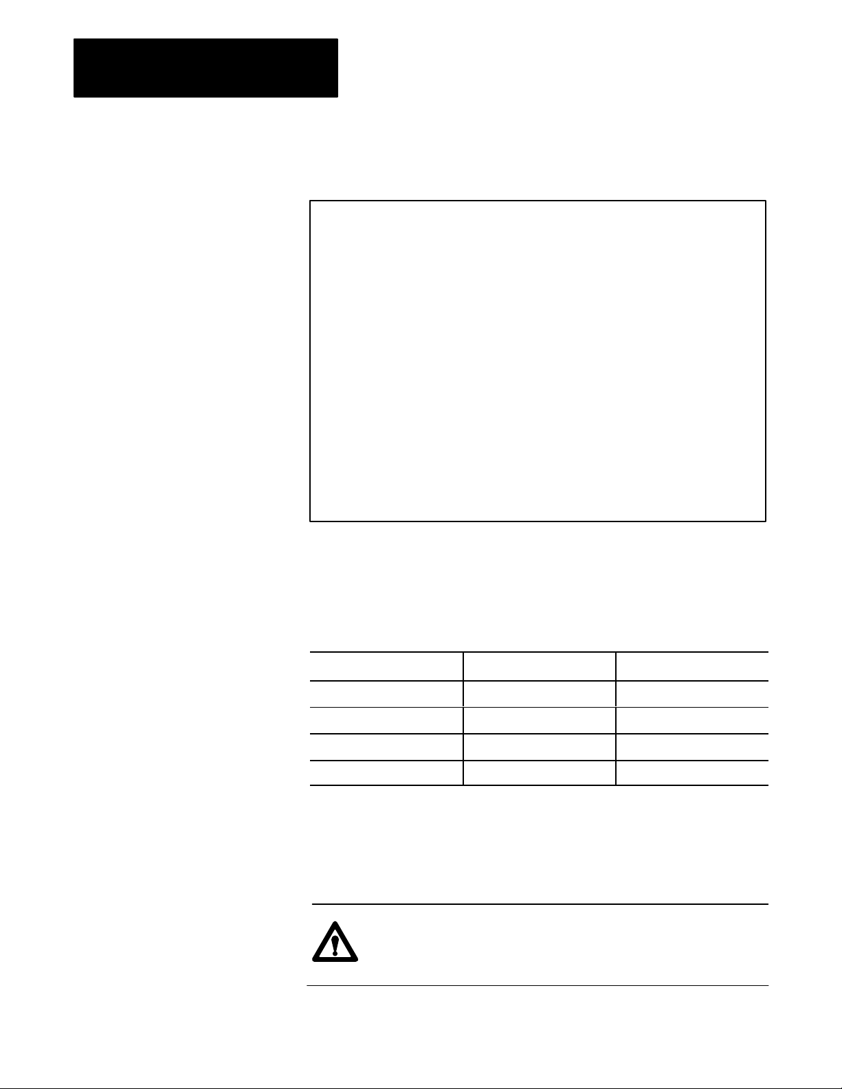
At the top of the 1775-S4B scanner’s front edge, LED indicators labeled
PASS and FAIL keep you informed on the general condition of the
1775-S4B scanner. These indicators have the following meanings:
Pass (green) Fail (red) Meaning
On Off Normal Operation
Off On Module Fault
On On Powerup or system reset
Off Off PLC3 processor is not on
The thumbwheel switch is below the PASS and FAIL indicators. Setting it
at a unique number (1 to 15) enables the PLC-3 processor to differentiate it
from another 1775-S4B scanner.
CAUTION: Do not change the thumbwheel setting on the
1775-S4B scanner while processor power is on. Equipment
damage could result.
22
Page 12

Chapter 2
I/O ScannerMessage Handling Module
2.1.3
I/O Channel Status
Indicators
Below the thumbwheel switch are four green LEDs labeled:
CH1
CH2
CH3
CH4
Each LED corresponds to one of the four I/O communication channels.
Each I/O channel can connect to a bulletin 1771 I/O chassis or a group of
chassis providing direct communication with the 1775-S4B scanner. Each
indicator has the following meanings:
If the LED is: Then:
On Proper communication exists between
1775S4B scanner and the I/O chassis on the
corresponding I/O channel.
Flashing A fault exists on one or more of the I/O chassis
on the corresponding I/O channel.
Off No I/O chassis are connected to the
corresponding I/O channel.
2.1.4
Backup Connector
2.1.5
Channel 5 Connector
2.1.6
Terminal Swing Arm
Below the I/O channel indicators is a connector labeled BACKUP. This
connector is not used.
Below the backup connector is a 25-pin D-shell connector labeled CH5.
This connector provides communication with an RS-232-C device such as
a data terminal, a computer, or a printer. Refer to chapter 3 for installation
information.
Near the bottom of the 1775-S4B scanner is a Terminal Swing Arm (cat.
no. 1775-WA). This swing arm contains the connection terminals for
channels 1 to 4 which scan I/O chassis. We discuss cable connections for
the I/O communication channels in chapter 3.
23
Page 13

Chapter 2
I/O ScannerMessage Handling Module
2.2
1775S4B
Scanner
Features and Functions
Now that you are aware of the 1775-S4B scanner’s hardware components,
this section summarizes the basic features and functions of the I/O
scanner-message handling module:
Features Functions
Four I/O communication
channels
Report generation channel To communicate with an RS232C compatible data terminal for
Status indicators To keep you informed on the 1775S4B scanner's status. These
Thumbwheel switch To distinguish one 1775S4B scanner from another. You can
Terminal swing arm To easily connect bulletin 1771 I/O chassis to the 1775S4B
To communicate with I/O Adapter Modules (cat. no. 1771AS) in
I/O chassis. You can connect up to 16 I/O chassis to one
1775S4B scanner I/O channel. The 1775S4B scanner can
communicate with 2,048 inputs and 2,048 outputs per scanner
total.
report generation. You can execute messages from your data
terminal or from a MSG instruction in the ladder diagram
program.
LEDs indicate the general module status and the active state of
each I/O communication channel.
insert up to 15 1775S4B scanners in one PLC3 system.
scanner. The terminal swing arm disconnects so you can easily
attach Twinaxial Cable (cat. no. 1770CD). An I/O chassis can
connect to a 1775S4B scanner up to 10,000 cable feet away.
2.3
Specifications
Location
Single slot in a PLC-3 processor chassis
Functions
I/O interface
Report generation
I/O Capacity
2,048 inputs and 2,048 outputs
Channels Per Module
4 I/O communication
1 RS-232-C communication
Communication Rate
57.6 baud or 115.2 kbaud (I/O channel)
110 to 19.2 kbaud (RS-232-C channel)
24
Page 14

I/O Channel Cable Length
10,000 cable feet (max)
Nominal I/O Scan Times
5.5 to 6.5ms for one I/O channel
6ms for two I/O channels
6ms for three I/O channels
6 to 6.5ms for four I/O channels
Backplane Current
2.7A from 5V DC circuit
2mA from +15V DC circuit
2mA from -15V DC circuit
Chapter 2
I/O ScannerMessage Handling Module
2.4
Chapter Summary
Environmental Conditions
Operational Temperature: 0 to 60° C (32 to 140° F)
Storage Temperature: -40 to 85° C (-40 to 185° F)
Relative Humidity: 5 to 95% (without condensation)
In this chapter, you were introduced to the:
Hardware components on the 1775-S4B scanner
Basic features and functions of the 1775-S4B scanner
Specifications of the 1775-S4B scanner
The next chapters describe installation procedures and PLC-3 LIST
selections for the 1775-S4B scanner.
25
Page 15

Chapter
3
Installing Your 1775S4B Scanner
3.0
Chapter Objectives
3.1
Inserting Your 1775S4B
Scanner
3.2
Using the 1775S4B
Scanner's RS232C
Channel
The 1775-S4B scanner provides the PLC-3 processor with an RS-232-C
compatible channel for report generation and a terminal swing arm for I/O
scanning. After reading this chapter, you should be able to:
Insert a 1775-S4B scanner into a PLC-3 system
Connect an RS-232-C device to the channel 5 connector on the
1775-S4B scanner
Connect I/O chassis to the terminal swing arm on the 1775-S4B scanner
The first step is inserting your 1775-S4B scanner. You can slide the
1775-S4B scanner into any slot of a PLC-3 Processor Chassis (cat. no.
1775-Al, 1775-A2). The chassis electromechanically interlocks helping to
guard against inserting or removing modules while power is on.
The channel 5, 25-pin connector provides RS-232-C communication to a
modem, computer, or data terminal for report generation capability. We
discuss report generation in chapter 5. The following two sections discuss
connecting RS-232-C devices to the 1775-S4B scanner.
3.2.1
Connecting RS232C
Devices
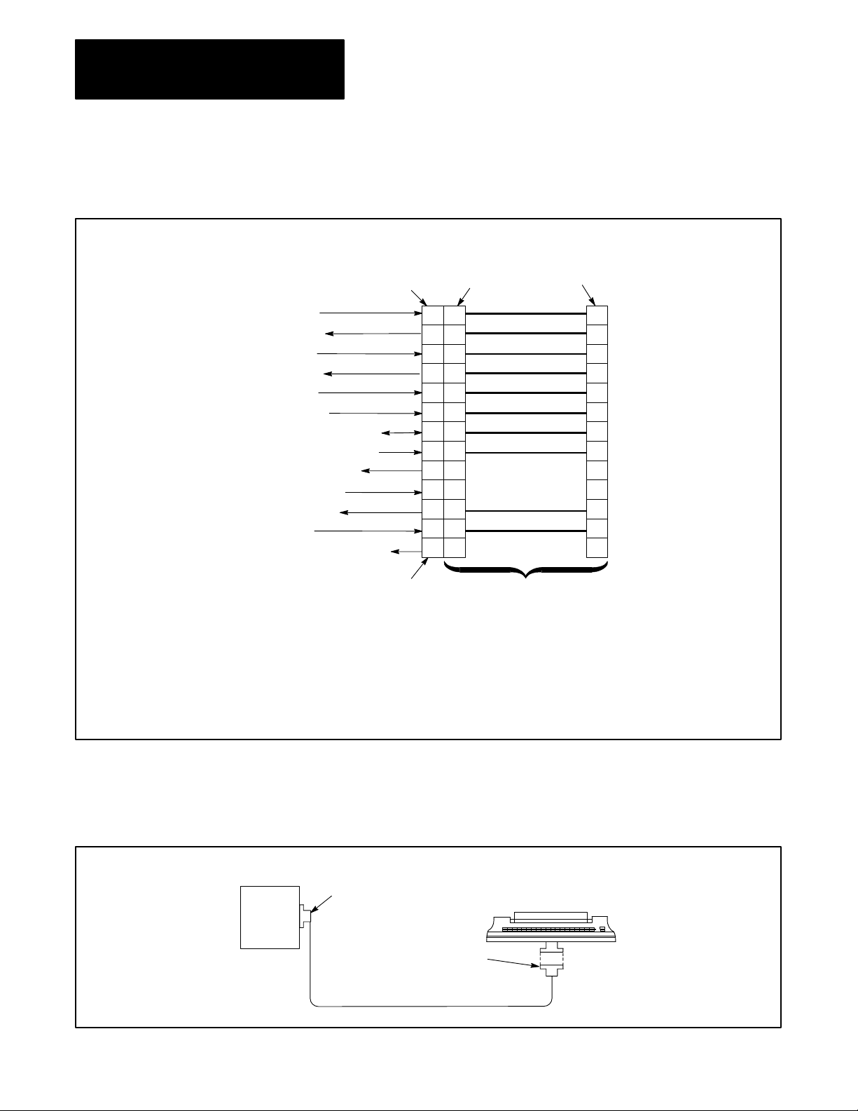
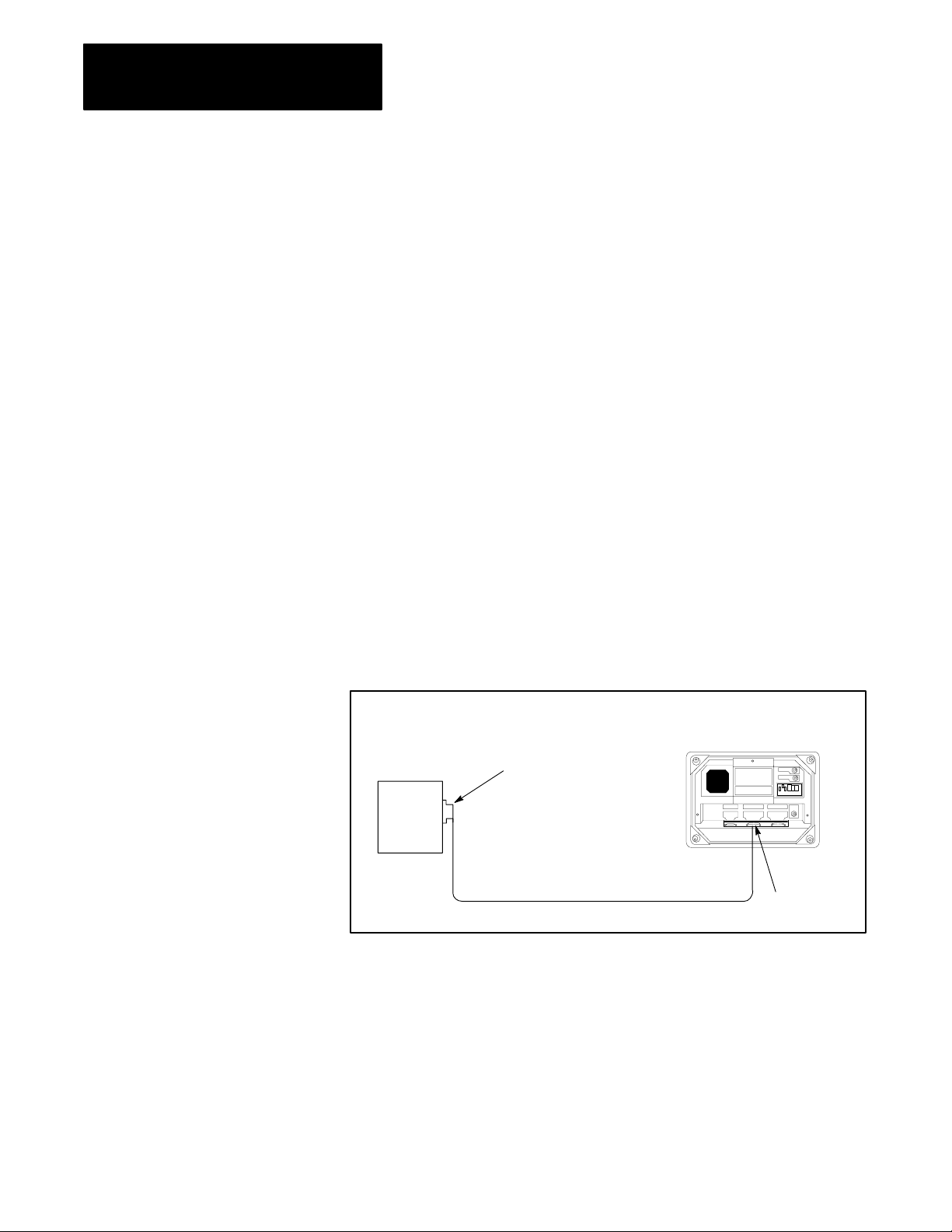
Figure 3.1 shows the pin assignments for the channel 5 connector. You can
use Peripheral Cable (cat. no. 1775-CDC) to connect RS-232-C data
terminals or computers to the 1775-S4B scanner. This peripheral cable is
15 feet or 4.6 meters long (figure 3.2). If you need more distance, you can
connect an RS-232-C device up to 50 feet or 15.2 meters from the
1775-S4B scanner by using Remote I/O Interconnect Cable (cat. no.
1778-CR), or equivalent, and two 25-Pin Connector Kits (cat. no.
1770-XXP). Figure 3.3 shows the appropriate wiring.
If an RS-232-C device must be more than 50 cable feet or 15.2 cable
meters from the 1775-S4B module, use a line driver/receiver or a modem.
You could also use the cable that comes with the RS-232-C device.
However, the connector must have a right angle hood; otherwise, the
PLC-3 processor door will not close.
31
Page 16
Chapter 3
Installing Your 1775S4B Scanner
Figure 3.1
Diagram of Peripheral Cable for Connecting RS232C Device to
Wiring
1775S4B Scanner
Protective
Ground
T
ransmitted Data
1
Received Data
2
Request to send
3
Clear to Send
3
Data Set Ready
Signal Ground (Connom Return)
3
Received Line Signal Detector
4
Isolated T
4
Received Data Return
2
Data T
5
Ring Indicator
4
Isolated T
ransmitted Data
erminal Ready
ransmitted Data Return
CH 5 Connector on
the 1775-S4B Scanner
1
This pin is for both long line and RS-232-C campatible transmission
2
Signals from the data terminal to these input pins have no ef
operation of the module.
3
The module always holds these output pins high (ON).
4
These pins are for long line transmission; they are not RS-232-C compatible.
5
The module always holds this output pin low (OFF).
25-Pin
Female
Connector
1
2
3
4
5
6
7
8
14
18
20
22
25
25-Pin
Male
Connector
(AA)
1
(BA)
2
(BB)
3
(CA)
4
(CB)
5
(CC)
6
(AB)
7
(CF)
8
14
18
(CD)
20
(CE)
22
25
Cat. No. 1775-CDC
Cable (15 ft. 4.6m)
25-Pin
Female
Connector
1
2
3
4
5
6
7
8
14
18
20
22
25
fect on the
32
I/O
Scanner
Message
Handling
Module
(Cat. No.
1775-S4B)
Figure 3.2
Connecting
an RS232C Device to the 1775S4B Scanner Using
Peripheral Cable
25-Pin
Male
Connector
25-Pin
Female
Connector
Cat.
No. 1775-CDC Peripheral Cable (15 ft. 4.6m)
Data T
erminal
(RS-232-C Compatible)
Page 17
Chapter 3
Installing Your 1775S4B Scanner
I/O
Scanner
Message
Handling
Module
(Cat. No.
1775-S4B)
I/O
ScannerMessage
Handling
Module
(Cat. No.
1775-S4B)
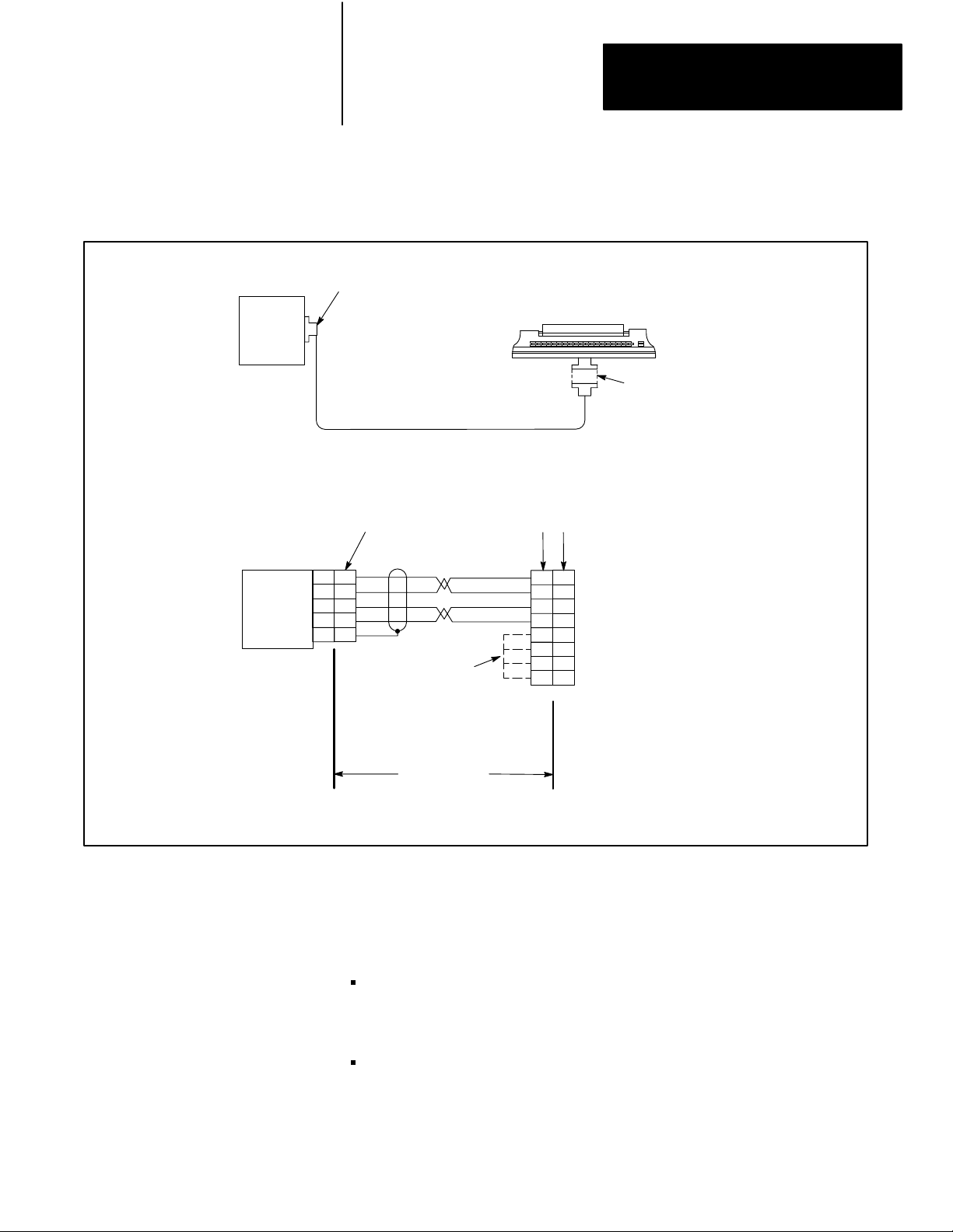
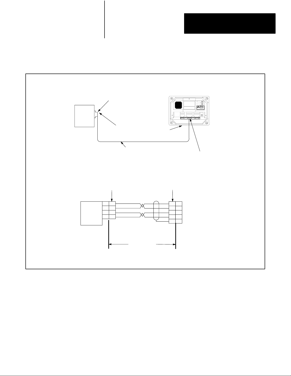
Figure 3.3
Connecting
I/O Interconnect Cable
UserSupplied
Cannon T
7
7
2
2
7
7
3
3
1 1
25Pin Male Connector;
ype DB2505, Male or equivalent
Cat.
No. 1778-CR Cable or equivalent
(50 ft. or 15.2 m maximum)
a)
Connection Diagram
UserSupplied
Connector
UserSupplied
Jumpers refer
to section 3.2
an RS232C Device to the 1775S4B Scanner Using Remote
UserSupplied
Connector,
as Appropriate
UserSupplied Connections
as Appropriate
[AB]
[BA]
[AB]
[BB]
[CB]
[CC]
[CD]
[CF]
7
7
2
2
7
7
3
5
6
20
8
Data T
3
5
6
20
8
erminal
(RS232C Compatible)
Cat. No. 1778-CR Cable
or equivalent
50 ft. or 15.2 m
maximum
b) Wiring Diagram
Some RS-232-C devices may require a high signal for a clear to send (CB)
signal at pin 5, a data set ready (CC) signal at pin 6, or a data carrier detect
(CF) signal at pin 8 for proper operation. Depending on your connections,
note the following:
If you are using the 1775-CDC cable to connect directly between the
1775-S4B scanner and the RS-232-C device or its cable, the 1775-S4B
scanner provides these signals.
If you are constructing a cable for the RS-232-C device, you can jumper
pin 20 to pin 5, 6, or 8 as required by the RS-232-C device.
33
Page 18
Chapter 3
Installing Your 1775S4B Scanner
The RS-232-C device should pull pin 20 high to provide its own signal.
This jumpering is shown by dashed lines in the wiring diagram of
figure 3.3.
3.2.2
Connecting an Industrial
Terminal
You can use the PLC-3 Industrial Terminal Cable (cat. no. 1775-CAT) for
connecting an industrial terminal to the 1775-S4B scanner. Refer to the
steps below for proper connection:
Step 1—Connect the end labeled INDUSTRIAL TERMINAL END to
channel B of the industrial terminal.
Step 2—Connect the end labeled PLC-3 END to the channel 5 connector
on the 1775-S4B scanner.
The 1775-CAT cable is 10 feet or 3 meters long (figure 3.4). If you want to
connect the industrial terminal up to 5,000 cable feet (1,524 cable meters)
away from the 1775-S4B scanner, refer to figure 3.5. Use 1778-CR cable
or equivalent cable and two 25-pin male connector kits (cat. no.
1770-XXP).
Figure 3.4
Connecting
Industrial T
an Industrial T
erminal Cable
erminal to the 1775S4B Scanner Using
Industrial T
(Cat. No. 1770-T1, T2, T3, or T4)
erminal System
34
I/O
Scannermessage
Handling
Module
(Cat. No.
1775-S4B)
25Pin Male
Connector with
Right-Angle Hood
Cat.
No. 1775CA
Industrial T
erminal Cable (10ft. 3 m)
T PLC3
Channel B
Page 19
Chapter 3
Installing Your 1775S4B Scanner
I/O
Scanner
message
Handling
Module
(Cat. No.
1775-S4B)
Figure 3.5
Connecting
an Industrial T
Remote I/O Interconnect Cable
RightAngle Hood
User-Supplied
Cannon T
UserSupplied
Connector
25Pin Male Connector
ype DB2505, Male, or equivalent
Cat. No. 1778CR Cable or equivalent
(5000 ft. or 1524m maximum)
a) Connection Diagram
erminal to the 1775S4B Scanner Using
Industrial T
(Cat. No. 1770T1, T2, T3, or T4)
,
UserSupplied
Connector
erminal System
Channel B
3.3
the 1775S4B
Using
Scanner'
s I/O T
Swing Arm
erminal
I/O
Scanner
Message
Handling
Module
(Cat. No.
1775-S4B)
25
25
14
14
18
18
3
3
25
25
2
18
3
1
Industrial
Terminal
Channel B
2
18
3
1
Cat. No. 1778CR
Cable or equivalent
5000 ft. or 1524 m
maximum
b) Wiring Diagram
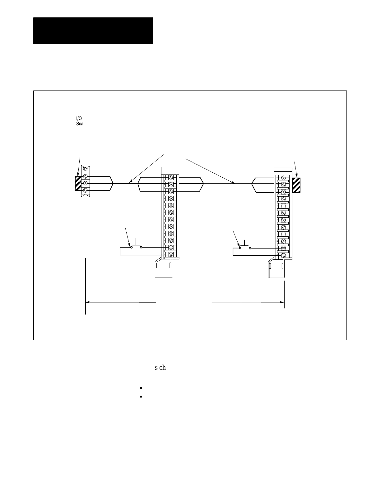
The I/O terminal swing arm provides cable connection for Twinaxial Cable
(cat. no. 1770-CD) which connects to 1771 I/O chassis. This swing arm
contains terminals for I/O channels 1 thru 4. Figure 3.6 shows how to wire
the 1770-CD cable to the terminals on the terminal swing arm.
35
Page 20
Chapter 3
Installing Your 1775S4B Scanner
Figure 3.6
Scanner Module I/O Channel Connections
I/O
Line 1
Shield
Line 2
Line 1
Shield
Line 2
Channel
No. 4
Channel
No. 2
Terminator
(Cat. No. 177)
Channel
No. 3
Blue
Channel
No. 1
Clear
T
winaxial Cable
Cat. No. 1770-CD
Line 1
Shield
Line 2
Line 1
Shield
Line 2
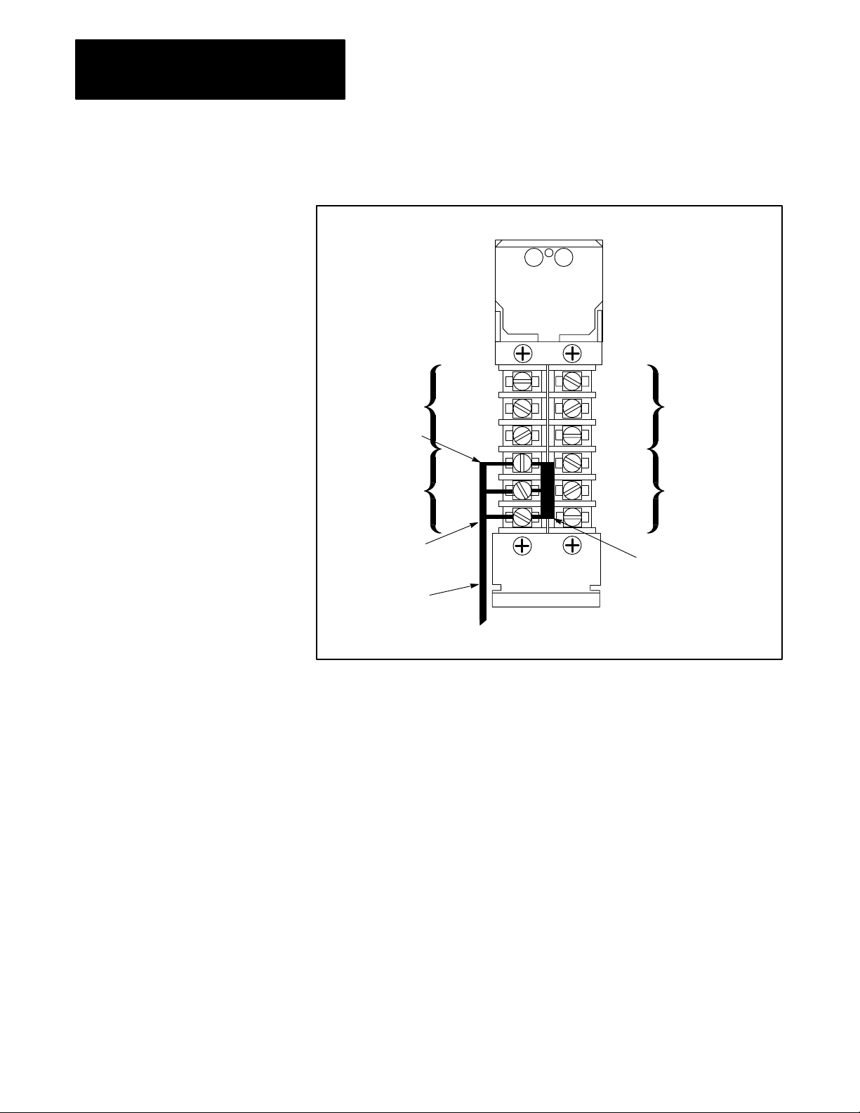
Figure 3.7 shows the terminal identification label which indicates the
proper connections for each I/O adapter module to an I/O channel. This
label is on the side of the module. The connections are made at screw
terminals on a wiring arm in front of each I/O adapter module.
36
Page 21
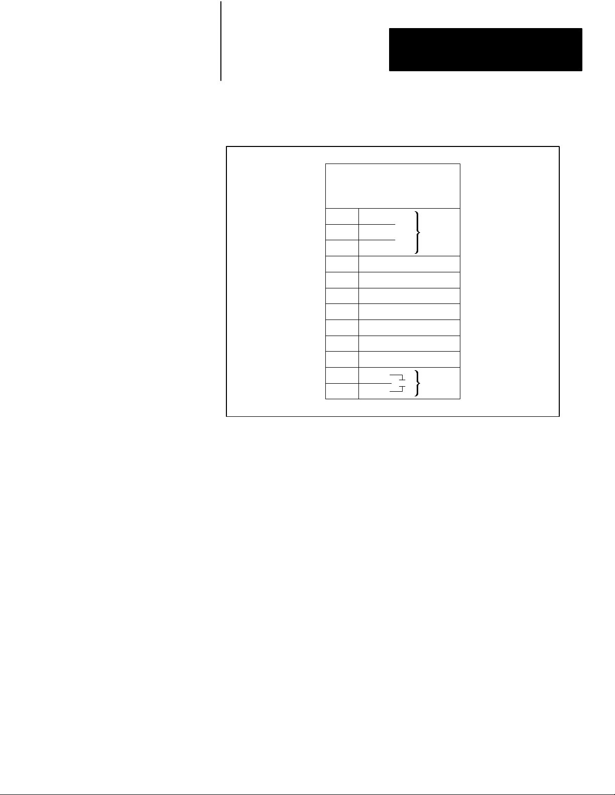
Figure 3.7
Adapter Module (cat. no. 1771AS) T
I/O
1
2
3
4
5
6
7
8
9
10
11
12
Chapter 3
Installing Your 1775S4B Scanner
erminal Identification Label
Terminal
Identification
Cat. No. 1771AS
Line
1
Shield
Line 2
No connection
No connection
No connection
No connection
No connection
No connection
No connection
IN
RET
Cable
Reset
Perform the following steps to make proper I/O channel connections:
Step 1—Connect the twinaxial cable in a serial (daisy chain) fashion from
the 1775-S4B scanner to each I/O chassis within the I/O channel
(figure 3.8).
Step 2—Connect the signal conductor with blue insulation to the LINE 1
terminal at the 1775-S4B scanner and at each I/O adapter module in the
I/O channel.
Step 3—Connect the signal conductor with clear insulation to the LINE 2
terminal. Connect the shield drain wire to the SHIELD terminal.
Step 4—Connect a Terminator (cat. no. 1770-XT) between the terminals at
each end of each I/O channel.
You can optionally connect a normally open, momentary contact switch
between terminals 11 and 12 at each I/O adapter module. You could then
use such a reset switch to reset the I/O adapter module if the PLC-3
processor detects a fault at the I/O chassis. Refer to the PLC-3
Programmable Controller Installation and Operation Manual (publication
1775-6.7.1, formerly 1775-800) for detailed information.
37
Page 22
Chapter 3
Installing Your 1775S4B Scanner
Figure 3.8
Channel Connections
I/O
I/O
Scanner
Module
Arm
Swing
(Car
. No. 1775-W
Terminator
(Cat. No.1770-XT)
Blue
Shield
Clear
A)
Optional
User-supplied
Pushbutton
for I/O Chassis
Restart
I/O Adapter
Module Field
Wiring Arm
(Cat. No. 1771-WB)
Twinaxial
Cable
(Cat. No. 1770-CD)
Blue
Shield
Clear
I/O Adapter
Module Field
Wiring Arm
(Cat. No. 1771-WB)
Terminator
(Cat. No. 1770-XT)
Blue Blue
Shield Shield
Clear Clear
Optional
User-supplied
Pushbutton
for I/O Chassis
Restart
3.4
Chapter Summary
38
10,000 cable ft or
3048 cable m maximum
In this chapter, you read installation procedures for:
Connecting an RS-232-C device to channel 5 for report generation
Connecting I/O chassis to the terminal swing arm for I/O scanning
Before you begin operating the 1775-S4B scanner, we suggest that you
double check all connections.
The next chapter describes LIST selections for the 1775-S4B scanner.
Page 23

Chapter
Operating the LIST Function
4
4.0
Chapter Objectives
4.1
Entering LIST
4.2
Configuring the RS232C
Communication Channel
The LIST function allows you to select parameters to operate the PLC-3
controller. After reading this chapter, you should be able to:
Select operating parameters for the RS-232-C communication channel
on the 1775-S4B scanner
Select operating parameters for the I/O communication channels on the
1775-S4B scanner
You can operate the LIST function for the 1775-S4B scanner through a
1770-T4 terminal or the data access panel on the PLC-3 Main Chassis (cat.
no. 1775-Al). Refer to the PLC-3 Programmable Controller Installation
and Operation Manual (publication 1775-6.7.1, formerly 1775-800) for
detailed information on operating the LIST function.
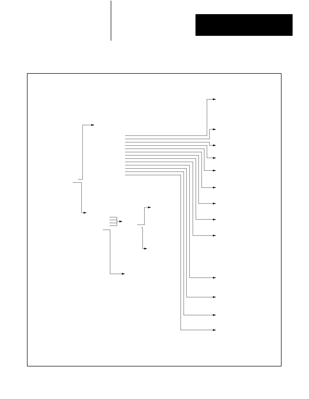
Figure 4.1 shows you the parameters that you can select for each channel.
We explain these parameters in the following sections.
If you select COMM CHAN to configure the RS-232-C communication
channel, you can make the following selections:
TTY (Printer) defaults
CRT defaults
Privileges
Echo
Line length
Pad characters
Tabs
Form feed
Mode
XON/XOFF
Communication rate (baud)
Parity
Stop bits
Data bits/character
ASCII code size
41
Page 24

Chapter 4
Operating the LIST Function
Reconfig
We explain these selections in the following sections.
42
Page 25
I/O Scanner02
Chassis 1 Slot 3
1 Comm Chan
2 I/O Chan
Enter Next>
Figure 4.1
Selections for the 1775S48 Scanner
LIST
02Comm Chan 5
1 TTY Defaults
2 CRT Defaults
3 Privileges
4 Echo
5 Line Length
6 Pad Char
7 Tabs
8 FF
9 Mode
10 XON/XOFF
1 Baud
1
12 Parity
13 Stopbits
14 Bits/Char
15 ASCII Code Size
16 Reconfig
Enter Next>
02I/O Chan 4Baud
I/O Scanner02I/O Chan
1 I/O Chan 1
2 I/O Chan 2
3 I/O Chan 3
4 I/O Chan 4
5 Racks
6 Auto Config
7 Reconfig
Enter Next>
02I/O Chan 4
1 Baud
2 * I/O Scan
3 Inactive
Enter Next>
02I/O Racks
1 * 077
2 100177
3 200277
4 300377
Enter Next:
Those selections shown in bold type affect the
operation of the module. The selections not shown
in bold type only cause a movement to another level
of LIST. The LIST display shows an asterisk (*) to
indicate the selection made.
1 57600
2 * 1
15200
3 Inactive
Enter Next>
02I/O Chan 4Chassis
1 003/2/0
2 005/2/2
3 006/2/6/I
4 005/4/4/I/F
5 007/8/0
Enter Next>
Chapter 4
Operating the LIST Function
02Chan
5Privileges
3
5
6
65
73
Enter Next>
02Chan 5Echo
1 * On
2 Off
Enter Next>
02Chan 5Line Length
Line Length 80
Enter Next>
02Chan 5Pad Char
Pad Char 0
Enter Next>
02Chan 5T
abs
1 * Expanded
2 Not Expanded
Enter Next>
02Chan 5FF
1 Expanded
2 * Not Expanded
Enter Next>
02Chan 5Mode
1 * CRT
2 Print
Enter Next>
02Chan 5XON/XOFF
1 * XON/XOFF
2 No XON/XOFF
Enter Next>
02Chan 5Baud Rate
1 110 Baud
2 150 Baud
3 300 Baud
4 600 Baud
1200 Baud
5
6
1800 Baud
7
2400 Baud
8
4800 Baud
9 *
9600 Baud
10
19200 Baud
Enter Next>
02Chan 5Parity
1 Even
2 Odd
3 * None
Enter Next>
02Chan 5Stopbits
1 * 1
2 1.5
3 2
Enter Next>
02Chan 5Bits/Char
1 * 8
2 7
Enter Next>
02Chan 5ASCII Code Size
1 8
2 * 7
Enter Next>
43
Page 26

Chapter 4
Operating the LIST Function
4.2.1
TTY (Printer) Defaults
The TTY defaults selection configures the RS-232-C communication
channel for report generation communication with a printer terminal. Table
4.A lists the parameter selections for TTY defaults. You can use the printer
terminal for report generation functions that we discuss in chapters 5
through 11.
Table 4.A
Channel
5 Default Selections
Parameter TTY Defaults CRT Defaults
Privileges
Echo
Line length
Pad Char
Tabs
Form feed
Mode
XON/XOFF
Baud
Parity
Stop bits
Bits/Character
ASCII Code Size
3, 5, 6, 65, 73
On
80
4
Expanded
Expanded
Print
XON/XOFF
300 Baud
None
1
8
7
3, 5, 6, 65, 73
On
80
0
Not Expanded
Expanded
CRT
XON/XOFF
9600 Baud
None
1
8
7
4.2.2
CRT Defaults
4.2.3
Privileges
44
The CRT defaults selection configures the RS-232-C communication
channel for report generation communication with a CRT terminal. Table
4.A lists the parameter selections for CRT defaults. You can use the CRT
terminal for report generation functions that we discuss in chapters 5
through 11.
You must configure the RS-232-C communication channel for TTY or
CRT defaults. If you make no selection, the channel configures for CRT
defaults.
The LIST function allows you to select operating parameters for the
RS-232-C communication channel on the 1775-S4B scanner. These
operating parameters are called privileges and are primarily a list of PLC-3
memory areas into which channel 5 has access. For example, if a report
generation message is to write into the message area of PLC-3 memory,
you must select privilege 5 which corresponds to the message area after
you select the privileges selection in LIST.
Page 27

Chapter 4
Operating the LIST Function
Some privileges, however, do not deal with PLC-3 memory areas. For
example, privilege 65 allows you to edit or delete report generation
messages. Table 4.B lists the available privileges. We describe all the
privileges below:
Privilege 0—System status area. Allows device on channel 5 to write to
the system status area of PLC-3 memory.
Privilege 1—System pointers area. Allows device on channel 5 to write
to the system pointer area of PLC-3 memory.
Privilege 2—Module status area. Allows device on channel 5 to write to
the module status area of PLC-3 memory.
Privilege 3—Data table area. Allows device on channel 5 to write to the
data table area of PLC-3 memory.
Privilege 4—Program area. Allows device on channel 5 to write to the
program area of PLC-3 memory.
Privilege 5—Message area. Allows device on channel 5 to write to the
message area of PLC-3 memory.
Privilege 6—System symbol area. Allows device on channel 5 to write
to system symbol area of PLC-3 memory.
Privilege 7—User symbol area. Allows device on channel 5 to write to
user symbol area of PLC-3 memory.
Privilege 10—Force table area. Allows device on channel 5 to write to
force table area of PLC-3 memory.
Privilege 65—Edit report generation messages. Allows device on
channel 5 to edit or delete report generation messages.
Privilege 73—Accept keyboard input. Allows device on channel 5 to
input data for report generation.
45
Page 28
Chapter 4
Operating the LIST Function
Table 4.B
Privileges
Privilege Number Description
0
1
2
3
4
5
6
7
10
65
73
1
indicates the default privileges.
Write access to system status area
Write access to system pointers area
Write access to module status area
Write access to data table area
Write access to program area
Write access to messages area
Write access to systems symbols area
Write access to user symbols area
Write access to force tables area
Edit or delete report generation messages
Accept keyboard input for report generation
1
1
1
1
1
To add a privilege to channel 5, type the number of the privilege. For
example:
At the privileges menu if you enter:
ENTER NEXT > 10
The PLC-3 processor adds privilege 10 (write access to force table area)
and redisplays the privileges list.
You can make a privilege independent of the memory protect keyswitch
position by typing /I after the privilege number. For example:
46
If you enter:
ENTER NEXT >3/I
The PLC-3 processor places /1 after privilege 3 (write access to data table
area) and redisplays the privileges list. Then the PLC-3 processor updates
the data table regardless of the memory protect keyswitch position.
To delete a privilege from a local channel, type /D after the privilege
number. For example:
If you enter:
ENTER NEXT > 4/D
The PLC-3 processor deletes privilege 4 (write access to the user program
area) and redisplays the privileges list.
If you do not specify privileges, the default privileges are 3, 5, 6, 65,
and 73.
Page 29

Chapter 4
Operating the LIST Function
4.2.4
Echo
4.2.5
Line Length
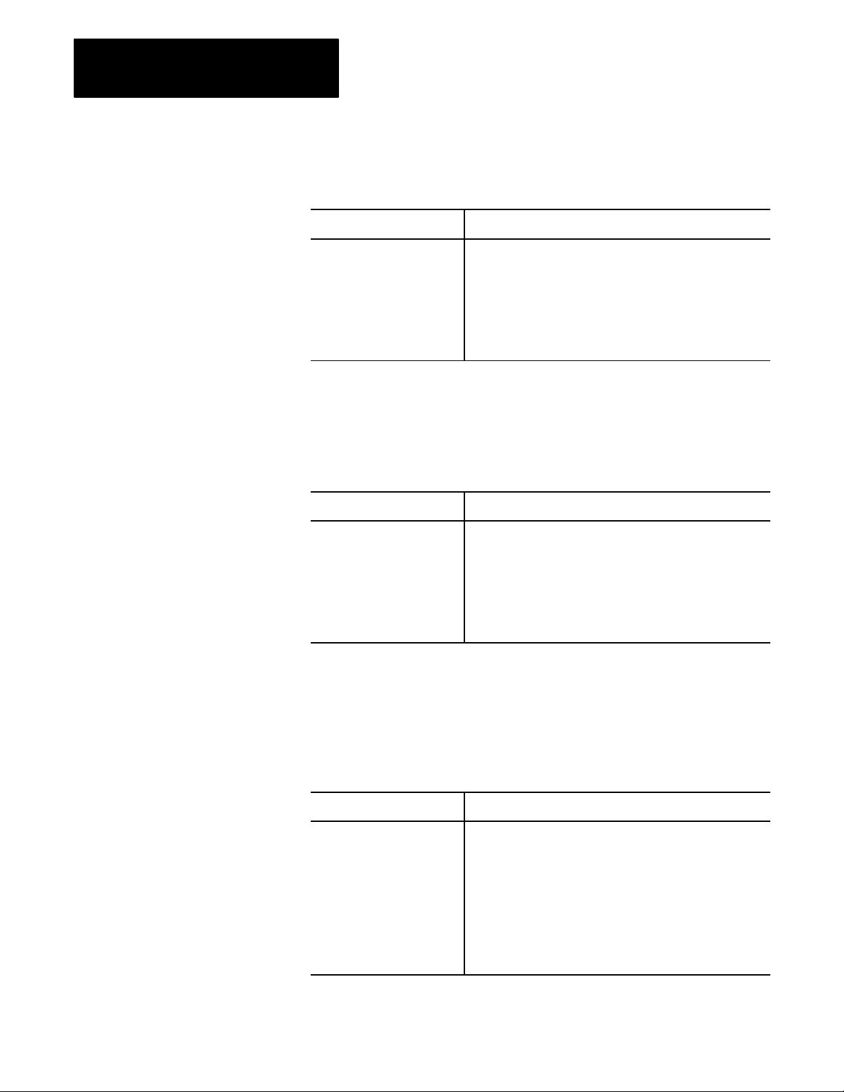
The echo selection determines whether channel 5 immediately transmits
back to the data terminal a copy of each character received from the data
terminal. To enable the echo selection, your RS-232-C device must be set
for full-duplex. Note the following:
If you: Then:
Select echo
Do not select echo
Each keystroke from the data terminal prints out or displays after
being echoed by the channel.
The keystrokes do not display, unless you can configure the data
terminal to do so directly.
The echo selection defaults to on.
You can select a line length value of 0 to 255 characters. If you select a
value of 1 to 255, a new line starts automatically whenever the line length
of a message exceeds the line length value selected.
As an example, consider message text stored with the intention of printing
on a 132-column printer. If an 80-column printer is used, selecting a line
length value of 80 automatically causes a new line to start after 80
characters. This prevents the end of each line from being lost. The default
line length is 80 characters.
4.2.6
Pad Characters
If you select value 0, a new line does not automatically start. You can use
the value 0 for many applications involving graphic displays.
After CR and LF characters are sent to an unbuffered printer to start a new
line, the printer needs some time to position the print head at the start of
the new line. NUL characters follow CR and LF characters to give the
printer this time. Pad characters (1 to 255) provide the number of needed
NUL characters. If no NUL characters are needed, enter a pad characters
value of 0. If you do not specify a pad character, this selection defaults
to 0.
47
Page 30
Chapter 4
Operating the LIST Function
4.2.7
Tabs
4.2.8
Form Feed
The tabs selection determines what the channel transmits for a tab
function:
If you select: Then:
Not expanded
Expanded
The channel sends an HT (tab) character in the message
transmission for each HT character in the stored message text.
Sending tab characters is only appropriate when transmitting to a
data terminal which supports a hardware tab function.
The channel considers a tab position to exist every 8 columns.
Each time a HT character is reached in the stored message, the
channel sends the number of SP characters to move the cursor
to the next tab position.
The default selection is not expanded.
The form feed selection determines what character or characters the
channel transmits to accomplish the form feed function:
If you select: Then:
Not expanded
Expanded
The channel sends a FF character in the transmission for each
FF character in the message text. Sending FF characters is only
appropriate when transmitting to a data which supports a
hardware form feed function.
The channel sends seven LF characters in the message
transmission for each FF character in the stored message text.
This selection does not provide a true form feed function, but it
can provide a separation between messages.
48
4.2.9
Mode
The default selection is expanded.
The mode selection determines what the 1775-S4B scanner does when you
enter a DEL (delete character) from your keyboard. You can make the
following selections:
If you select: Then:
CRT
Print
A DEL character causes the 1775S4B scanner to send back the
characters BS, SP, BS to erase the character from the screen.
A DEL character causes the 1775S4B scanner to send back the
character being deleted so that it prints again with a slash (/)
character on each side. For example, if you type an E, you would
see it printed as:
E
If you then delete it, you would see:
E/E/
Page 31

Chapter 4
Operating the LIST Function
With either selection, a DEL character deletes the previous character
entered. The default selection is CRT.
4.2.10
XON/XOFF
The XON/XOFF selection determines whether the 1775-S4B scanner
responds to XON and XOFF characters received from the data terminal.
Some data terminals can receive data transmissions at a faster rate than
they can print. They hold the received data in a buffer until the printing can
catch up during the time between transmissions from the module.
However, when a long message is transmitting, this buffer can become full.
Therefore, the 1775- S4B scanner provides an XON/XOFF hand-shaking
function which temporarily inhibits data transmissions until the buffer has
room. To use this hand-shaking function, you can generate the following
characters:
DC3 (XOFF) character generates automatically when the buffer is full
or if you enter [CTRL] S from the keyboard.
DC l (XON) character generates automatically when the buffer is full or
if you enter [CTRL] Q from the keyboard.
CAN (cancel) character generates if you enter [CTRL] X or [BREAK]
from the keyboard.
This selection operates as follows:
If you select: Then:
XON/XOFF
NO XON/XOFF
When the data terminal sends the ASCII character DC3 (XOFF),
the 1775S4B scanner is inhibited from transmitting until it
receives the ASCII character DC1 (XON).
You can use the ASCII character CAN (cancel) to abort the
suspended transmission. The 1775S4B scanner ignores any
other character.
The 1775S4B scanner does not respond to any DC3 (XOFF)
character received from the data terminal.
The default selection is XON/XOFF.
49
Page 32

Chapter 4
Operating the LIST Function
4.2.11
Communication Rate
4.2.12
Parity
The rate at which the 1775-S4B scanner communicates with RS-232-C
devices connected on its channel 5 connector is the communication or baud
rate. You can select one of the following communication rates:
110 Baud
150 Baud
300 Baud
600 Baud
1200 Baud
1800 Baud
2400 Baud
4800 Baud
9600 Baud
19200 Baud
Select the communication rate by typing the number corresponding to the
desired rate. The 1775-S4B scanner displays an asterisk next to the current
communication rate. The default selection is 9600 Baud.
The 1775-S4B scanner can communicate through channel 5 using the
following parity selections:
4.2.13
Stop Bits
If you select: Then:
Even
Odd
None
The channel transmits an even parity bit with each character and
checks for an even parity bit in each character received.
The channel transmits an odd parity bit with each character and
checks for an odd parity bit in each character received.
The channel does not transmit a parity bit and does not check for
a parity bit in each character received.
The 1775-S4B scanner displays an asterisk next to the current parity state.
The default parity selection is none.
You can specify the number of stop bits that the 1775-S4B uses to
communicate with its RS-232-C communication channel. The stop bit
selections are 1, 1.5, or 2. The 1775-S4B scanner displays an asterisk next
to the current stop bit selection. To change the number of stop bits, type the
number corresponding to the desired selection. The default stop bits
selection is 1.
410
Page 33

Chapter 4
Operating the LIST Function
4.2.14
Data Bits Per Character
4.2.15
ASCII Code Size
4.2.16
Reconfigure
The bits/char selections are 7 or 8. The channel transmits the selected
number of data bits per character. The channel only accepts characters
received with the selected number of data bits per character. The default
selection is 8 data bits per character.
The ASCII code size selections are 7 or 8. You use this selection when 8
data bits per character is selected. Then select one of the following:
If you select: Then:
7
8
The RS232C communication channel uses the first 7 bits only
in decoding the character transmitted.
The RS232C communication channel uses all 8 bits in
decoding the character transmitted.
The default ASCII code size is 7.
The reconfigure selection implements the channel 5 selections. For
example, if you select CRT defaults, the 1775-S4B scanner does not
implement the change until you select reconfigure. In response to selecting
reconfig:
4.3
Configuring the I/O
Communication Channels
If channel 5: Then:
Is not currently executing
Is currently executing
The 1775S4B scanner reconfigures the channel immediately.
The 1775S4B scanner waits until the task completes executing
before it reconfigures the channel.
When the 1775-S4B scanner reconfigures the channel, the asterisk beside
the reconfiguration selection disappears.
If you select I/O CHAN to configure an I/O communication channel, you
can select the following parameters:
I/O Chan 1
I/O Chan 2
I/O Chan 3
I/O Chan 4
Racks
Auto Config
Reconfig
We explain these parameters in the following sections.
411
Page 34

Chapter 4
Operating the LIST Function
4.3.1
I/O Channel Configuration
4.3.1.1
Communication Rate
4.3.1.2
I/O Chassis Scanning
Sequence
If you select an I/O channel, you can make the following selections for the
corresponding I/O communication channel:
Communication rate (baud)
I/O scan
We explain these selections in the following sections.
You can select one of the following communication rates for the
corresponding I/O communication channel:
If you select: Then:
57.6 kbaud
115.2 kbaud
You can change the order of execution for an I/O scan of the corresponding
I/O communication channel by selecting the I/O scan selection in LIST.
When you configure an I/O channel for I/O scan, list the I/O chassis in the
order that you want the 1775-S4B scanner to communicate with them. This
allows you to assign a higher priority to some I/O chassis than to others by
listing the higher priority chassis more than once.
The maximum I/O channel cable length can be 10,000 feet.
The maximum I/O channel cable length can be 5,000 feet.
412
As an example, if there are six entries in the I/O chassis list, and entries 1
and 4 are the same, then the chassis listed under entries 1 and 4 will be
updated twice as often as the other chassis. You can list a chassis as often
as you desire, provided that the list contains no more than 32 entries.
Each I/O chassis is listed once in the default configuration at initial
powerup or after an autoconfigure.
When forming the I/O chassis list, remember the following considerations:
Rack numbers which are not assigned consecutively cause greater
memory requirements by allocating memory for unused racks.
No more than 16 I/O adapters can connect to one I/O communication
channel on the 1775-S4B scanner.
No more than 16 different rack numbers can be assigned to one
1775-S4B scanner.
When using complementary or duplicate I/O, two chassis with the same
rack and starting module group numbers must be on different channels
Page 35

Chapter 4
Operating the LIST Function
of the same 1775-S4B scanner. Refer to the PLC-3 Programmable
Controller Installation and Operations Manual (publication 1775-6.7.1,
formerly 1775-800) for detailed information on complimentary and
duplicate I/O.
Rack number 778, is used for internal PLC-3 communication. Do not
assign this number to an I/O rack (although you can use the associated
addresses for internal storage).
Use the following format to enter chassis in the chassis list:
<entry number>/<rack number>/<chassis size>/
<starting module group number>/<attributes >
Entry number defines the position of the entry in the chassis list. For
example, to insert an entry between the third and fourth entries, use entry
number 4. The new entry becomes the fourth entry, and all entries
numbered 4 or greater have their numbers incremented by one.
Rack number is the I/O chassis’ I/O rack number, in octal. The rack
number must be within the range of the rack group selected for the
1775-S4B scanner (refer to section 3.2). The last two digits of the rack
number must correspond to the switch settings on the I/O adapter module
in the I/O chassis.
Chassis size is the number of module groups in the chassis. You can enter:
2 for a 32 I/O chassis
4 for a 64 I/O chassis
8 for a 128 I/O chassis
Starting module group is the lowest numbered module group in the chassis.
It can be 0, 2, 4, or 6.
Attributes can be:
I if the chassis is for inputs only
F if a fault in the chassis is to be considered a major fault
You can have 0, 1, or 2 attributes associated with the chassis.
You can delete entries from the rack list by typing the entry number and
pressing [ENTER]. For example:
To delete the third entry in the rack list, type:
3 [ENTER]
413
Page 36

Chapter 4
Operating the LIST Function
The 1775-S4B scanner removes the third entry in the rack list and
redisplays the rack list.
An asterisk (*) appearing before an entry in the rack list indicates that the
corresponding I/O chassis or I/O adapter module is faulted.
4.3.2
I/O Rack Group Selection
4.3.3
Reconfig and Auto Config
The I/O rack group selection in LIST selects the range of I/O rack numbers
that the I/O scanner module can address. Presently, the PLC-3 controller
uses only rack number 0 to 76
, and the first rack group is selected by
8
default, so you do not have to make a selection here.
The subscript (
If you plan to use rack numbers greater than 37
) indicates that the value is expressed in an octal format.
8
, consider the following:
8
Racks numbered greater than 378 increase the I/O scan time.
The amount of memory required for the input and output sections
depends on the highest rack number containing inputs or outputs,
respectively. Therefore, skipping rack numbers is an inefficient use of
memory.
The I/O channel portion of LIST includes selections for reconfig and auto
config. A reconfig implements other changes which you made in LIST. For
example, if you list an I/O chassis three times in the rack list, and you
change the rack list to include that chassis 6 times, the 1775-S4B scanner
does not change its polling sequence until you select reconfig. Reconfig
works for the all the I/O communication channels. Therefore, you can
reconfigure the I/O communication channels once, after making all I/O
channel selections, instead of making separate reconfigure selections for
each I/O channel.
414
If an asterisk is displayed next to the reconfig selection, change(s) have
been requested but not implemented. Upon selecting reconfig, the
1775-S4B scanner implements the changes and removes the asterisk.
CAUTION: If the PLC-3 processor is in the run mode and
executing block transfers, selecting reconfig could cause a bad
address fault to occur.
Page 37

Chapter 4
Operating the LIST Function
If this situation occurs you should:
Clear the bad fault address in a fault routine
Clear the block transfer bit
Restart the block transfer in the ladder diagram program
Auto config first creates a new I/O chassis list in which each I/O chassis
has equal priority with no attributes assigned. Then a reconfiguration
executes.
The 1775-S4B scanner performs an auto configure at powerup under the
following conditions:
No I/O channel configured for I/O scan has entries in the rack list.
Neither auto configure nor reconfigure has been selected during a
previous powerup (at least since the last time you cleared memory).
When forming the I/O chassis list during an auto configuration, the
1775-S4B scanner polls all valid addresses (rack 0 to 768). If the
1775-S4B scanner receives response to an address, it adds that I/O rack
address to the list. To assign attributes or priorities to the I/O chassis, add
them manually through LIST and reconfigure the I/O channel.
You can only perform an auto configuration when:
PLC-3 processor is in program load mode.
Power is applied to the I/O chassis.
Switch 2 of each I/O chassis is set to “on” to allow the I/O chassis to be
restarted from the PLC-3 processor.
If power is not applied to the I/O chassis, the PLC-3 processor attempts to
perform an auto configuration, and since the I/O chassis does not respond,
the 1775-S4B scanner does not enter it in the I/O chassis list. For an entry
to get into the I/O chassis list in auto config, a valid communication path
must exist between the 1775-S4B scanner and the I/O adapter module for
the I/O chassis.
415
Page 38

Chapter 4
Operating the LIST Function
4.4
Chapter Summary
In this chapter, you read about PLC-3 LIST selections for the 1775-S4B
scanner. You can access LIST from the PLC-3 front panel or the RS-232-C
channel (channel 5) on the 1775-S4A scanner. Upon selecting the
1775-S4B scanner:
Select COMM CHAN to configure channel 5
Select I/O CHAN to configure an I/O channel
The remainder of this publication describes the 1775-S4B scanner’s report
generation capability. If you do not use this capability, you do not need to
read the remaining chapters.
416
Page 39

Chapter
5
Getting Started in Report Generation
5.0
Chapter Objectives
5.1
Introduction
The 1775-S4B scanner uses a programming language for report generation
to print or display formatted text and data. After reading this chapter, you
should be able to:
Understand the command line structure
Write and execute a simple procedure
Execute a procedure using the message instruction in a ladder diagram
program
Before you start generating reports with your 1775-S4B scanner, you need
to understand certain key concepts:
Report generation—A programming language that the 1775-S4B
scanner uses to print or display formatted text and data.
Procedure—A collection of report generation command lines that the
1775-S4B scanner uses to generate formatted text and data.
Report—The output generated when a procedure is executed. For
example, shift report, machine status report, or downtime report.
5.2
Command Line Format
We refer to these terms throughout the discussion of report generation for
the 1775-S4B scanner.
The general format for a command line that you will use to generate
reports is:
<command> </modifier> <parameters> <;comment>
The command tells the 1775-S4B scanner what to do. The 1775- S4B
scanner only recognizes one command per command line.
The optional modifier tells the 1775-S4B scanner which way to execute the
command.
The parameters tell the 1775-S4B scanner what data to change.
51
Page 40

Chapter 5
Getting Started in Report Generation
The optional comment tells someone reading the procedure what the
command line does. The 1775-S4B scanner accepts the semicolon (;)
delimiter as an instruction to ignore the rest of the line. So, you can use the
semicolon to document command lines in a procedure.
As an example, suppose you enter the line:
P ‘FIRST SHIFT PRODUCTION’;TITLE OF REPORT
P is the abbreviation for the print command which tells the 1775-S4B
scanner to print out the data FIRST SHIFT PRODUCTION. TITLE OF
REPORT is the comment which tells what the command line prints out.
5.3
Getting Started
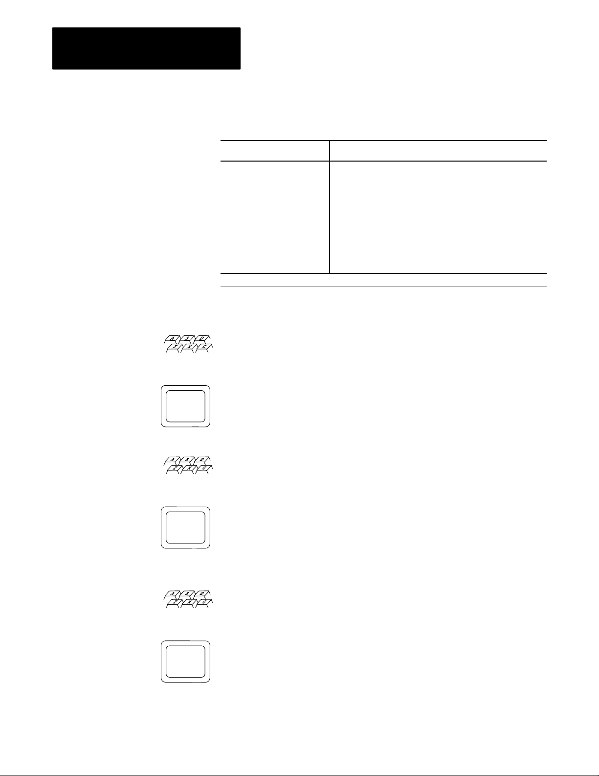
Now that you have been introduced to report generation, let’s do some
programming. In describing report generation programming, we use the
following icons to indicate your action and the 1775-GA module’s
response:
shows your input. The actual input characters are shown in
blue.
shows the 1775-GA module’s response to your input.
Before you program your 1775-S4B, you need to perform the following
steps:
Step 1—Configure the RS-232-C channel through LIST (chapter 4).
Step 2—Connect the data terminal to the channel 5 connector on the
1775-S4B scanner. These connections are described in chapter 3.
Step 3—If you are using an industrial terminal, select alphanumeric mode.
This selection makes the industrial terminal function as a data terminal.
Then make sure you select the same communication options for the
industrial terminal that you selected in LIST for channel 5 on the
1775-S4B scanner.
52
Step 4—Press [ENTER] or [RETURN]. The terminal displays the prompt:
S4B>
You are now ready to use your 1775-S4B scanner for report generation.
Page 41

Chapter 5
Getting Started in Report Generation
5.4
Executing
Procedure
a Simple
If you have the S4B> prompt on your CRT, you can create and execute
report generation procedures. The first step is to create the procedure by
entering the edit mode.
Simply type:
Ed @TEST1 [ENTER]
ED is the abbreviation for the edit command. The edit command is a report
generation command that enables you to create and store a new procedure
or edit an existing procedure. Also, you may notice that an (@) sign
precedes the first character in the procedure name. The 1775-S4B scanner
interprets an @ sign as a system symbol delimiter and accepts the
characters that follow as the procedure name. Following the @ sign, you
can use up to eight characters to name your procedure. Report generation
accepts any alphanumeric character(s) and the underscore character(s) (_)
for procedure names. Procedures names must start with a letter following
the @ sign.
NOTE: If you are using an industrial terminal to execute report generation
procedures, you cannot use lower case letters to name a procedure as the
industrial terminal does not recognize lower case letters. However, the
1775-S4B scanner does recognize lower case letters.
After you enter the command line above, the 1775-S4B scanner enters the
edit mode by displaying the following lines on the CRT:
<EOB>
*
<EOB> means end of block and signifies that the file, or the memory area
for the procedure is currently empty.
Next, you have to tell the 1775-S4B scanner that you want to insert some
text. So type:
I [ENTER]
When the cursor moves to the line after the asterisk, the 1775-S4B scanner
is ready for you to enter a line.
Type:
P ‘PRINTING ON THE’[ENTER]
P ‘SCREEN’[ENTER]
53
Page 42

Chapter 5
Getting Started in Report Generation
The 1775-S4B scanner’s line pointer or cursor moves to the next line.
Now exit the insert mode by pressing [ENTER].
The 1775-S4B scanner returns the * signifying the edit mode.
Then press E followed by [ENTER] to exit the edit mode.
The 1775-S4B scanner returns the S4B> prompt. You can now execute
your procedure.
Just type:
S4B> @TEST1
If you followed the instructions, the CRT displays the lines:
PRINTING ON THE
SCREEN
S4B>
Figure 5.1 summarizes the instructions presented in this section.
Figure 5.1
Creating
and Executing a Simple Procedure
S4B> ED @ TEST1
<EOB>
*I
P `PRINTING ON THE'
P `SCREEN'
S4B> @ TEST1
PRINTING ON THE
SCREEN
S4B>
54
Page 43

Chapter 5
Getting Started in Report Generation
Now type:
S4B> DI [ENTER]
DI is the abbreviation for the directory command. The directory command
returns:
All stored procedure names
Extended address of all procedures
Number of words used by each procedure
If you made a mistake while entering the procedure, you can edit your
procedure. Editing instructions are discussed in chapter 7 of this manual.
5.5
Executing Procedures from
the Message Instruction in
the User Program
In addition to commanding the execution of a procedure from the terminal,
you can use the message send instruction to execute a report generation
procedure from a ladder diagram program. You simply specify an extended
address of the 1775-S4B scanner which enables it to execute the procedure.
When the logic of the rung in the ladder diagram program is true, the Main
Processor Module (cat. no. 1775-LI, L2), or the (CPU), alerts the
1775-S4B scanner to execute the specified procedure. The CPU continues
to scan the rest of the program after alerting the 1775-S4B scanner. The
1775-S4B scanner then executes the procedures and turns on the done bit if
the procedure executes properly. If a problem occurs during procedure
execution, the 1775-S4B scanner turns on the error bit, and an error code
displays in the MSG instruction block.
The message instruction requires the following parameters:
Control file address
Channel address
Message type
Procedure name
The control file address is the data table file address that the PLC-3
processor uses to store the message status bits, error code, channel address,
and procedure name. The control file should be a binary file and can have a
starting word address other than zero. The CPU uses this file to locate the
1775-S4B scanner to execute the procedure. This file must be at least ten
words long.
55
Page 44

Chapter 5
Getting Started in Report Generation
The channel address is the extended address of the 1775-S4B scanner that
executes the procedure. This address has the following format (figure 5.2):
E2.7.t
where:
E2 = the module status area of PLC-3 memory
7 = the 1775-S4B scanner section of the module status area
t = the thumbwheel number on the 1775-S4B scanner
Figure 5.2
Instruction Extended Addressing Format
MSG
Module status
area of PLC3
memory
1775S4B scanner
section of module
status area
1775S4B scanner
thumbwheel
number
The message type must always be one, and the message itself should be a
report generation procedure name.
An example program using the message send instruction to execute a
report generation procedure appears in figure 5.3.
Figure 5.3
Example
Rung Which Executes a Report Generation Procedure
I0012
12
MSG
MESSAGE TYPE 1
CTL=FB005:0000= 0
CHANNEL E2.7.1
@TIME
STAT
(EN)
STAT
(DN)
STAT
(ER)
12
15
13
56
Page 45

Chapter 5
Getting Started in Report Generation
5.6
Control
Modes
As we have described in this chapter, you can:
Create and execute report generation procedures from the S4B> prompt
Call for procedures to execute from MSG instructions in your ladder
diagram program
The communication that occurs between the RS-232-C device on channel 5
of the 1775-S4B scanner can be in one of two control modes:
Command mode—The data terminal keyboard has direct control over
the operation of the 1775-S4B scanner. When you execute a procedure
at the S4B> prompt, you are in the command mode.
Ladder diagram mode—The ladder diagram program has direct
control over the operation of the 1775-S4B scanner. When a procedure
executes from the MSG instruction to an RS-232-C device connected to
channel 5 on the 1775-S4B scanner, you are in the ladder diagram
mode.
Figure 5.4 shows you the report generation control modes and how to
move from one to another.
57
Page 46

Chapter 5
Getting Started in Report Generation
Initialization
Figure 5.4
Generation Control Modes
Report
Ladder
Diagram
Program
in
Control
MSG Instruction
or
Print
Execute
Procedure
Procedure completed
[BREAK] or [CTRL] [X]
Command Mode in Control
S4B> is output to the data terminal to prompt
[RETURN]
the operator upon return to this mode after
completing a command and after each [RETURN].
Direct Command
Procedure completed
[BREAK] or [CTRL] [X] or
@ <procedure name> [RETURN]
Execute
Procedure
• Print
• Directory
• Create
• Delete
• Copy
• Rename
Completed
E [RETURN]
ED @<procedure name> [RETURN]
Edit
Mode
When you turn on your PLC-3 processor it initializes with ladder diagram
mode in control. So if you connect an RS-232-C device to the channel 5
connector on the 1775-S4B scanner, report generation procedures sent
from MSG instructions in your ladder diagram program will execute at the
RS-232-C device. When a procedure completes executing, ladder diagram
mode remains in control. Thus, you can execute consecutive procedures
from the ladder diagram program.
58
Now if you press [ENTER] or [RETURN] after initialization or after a
message procedure has been executed, the S4B> prompt displays at the
RS-232-C device. This prompt indicates that the command mode is in
control. In command mode, you can execute or edit report generation
procedures or enter report generation commands from your keyboard to
operate report generation. We describe report generation operation in the
following chapters. The report generation commands listed in figure 5.4
are described in chapter 10.
Now if you press [BREAK] or [CTRL] X while you are in the command
mode, the following message displays:
Page 47

Chapter 5
Getting Started in Report Generation
REPORT GENERATION ABORTED
At this point, ladder diagram mode is in control.
If the ladder diagram program calls for the 1775-S4B scanner to execute
report generation commands or procedures while the command mode
controls the 1775-S4B scanner, the 1775-S4B scanner does not respond to
the ladder diagram program immediately. In this case, the 1775-S4B
scanner stores as many as 4 report generation instructions in a ladder
diagram program until the 1775-S4B scanner switches to ladder diagram
control. If the ladder diagram program contains more than 4 report
generation instructions and you switch the 1775-S4B scanner to ladder
diagram mode:
The 1775-S4B scanner executes the first 4 instructions in the order that
they were stored.
5.7
Chapter Summary
The 1775-S4B scanner executes any remaining instruction(s) in random
order.
In this chapter, you were introduced to report generation on the 1775-S4B
scanner. The remainder of the publication describes the various parameters,
commands, and functions used to generate reports on the 1775-S4B
scanner.
59
Page 48

Logical Addressing for
Report Generation
Chapter
6
6.0
Chapter Objectives
6.1
Introduction
In addition to creating text in procedures, you can use report generation to
manipulate data within a specific area of PLC–3 memory. After reading
this chapter, you should be able to:
Use data table addressing to specify a memory area
Use extended addressing to specify a memory area
Logical addressing for 1775–S4B scanner report generation is similar to
logical addressing for the PLC–3 front panel or the industrial terminal. The
dollar sign ($) delimiter tells the 1775–S4B scanner that the following data
denotes a PLC–3 memory address. You can specify PLC–3 addresses in
two ways:
Data table addresses
Extended addresses
We discuss the formats for each of these logical addressing methods in the
following sections.
6.2
Data Table Addressing
You can specify data table sections of memory by using data table
addressing. In data table addressing, you follow the $ sign with the data
table section specifier. Then you can specify a file, word, and/or bit. Table
6.A shows the data table section specifiers. You must use a colon before
the word number.
You can specify an octal address format for data table addresses by
entering a leading zero in the bit position of the address. Using this format
can make your report generation procedure compatible with ladder
diagram program addressing and I/O terminal numbering. Figure 6.1
shows how the bit numbering formats in report generation correspond to
the bit numbering format within a PLC–3 memory word.
61
Page 49

Chapter 6
Logical Addressing for Report Generation
Some examples appear below:
Data Table Address Description
$B1:5 This address specifies binary file, 1, word 5.
$D0:1 or $D:1 These addresses specify the same address, decimal file 0
word 1. If you are specifying file 0, you need not enter a zero
after the section specifier.
$TPRE:57 This address specifies the preset of timer 57.
$B1:5/12 This address specifies binary file 1, word 5, bit 12 decimal.
$B1:5/12 or $B1:5/014 Both addresses specify binary file 1, word 5, bit 12 decimal. In
the second example, 014 represents the octal value for 12. To
enter a value in octal, enter a zero before the value.
Table 6.A
T
able Section Specifiers
Data
Section Specifier Extended Address Data Table Section
O
I
T
C
N
F
D
B
A
H
P
S
1
You can only access these sections through extended addressing
3.1.1
3.1.2
3.1.3
3.1.4
3.1.5
3.1.6
3.1.7
3.1.8
3.1.9
3.1.10
3.1.12
3.1.13
Output
Input
Timers
Counters
Integers
Floating Point
1
Decimal
Binary
ASCII
High Order Integers
1
Pointers
Status
Figure 6.1
Numbering Formats
Bit
For
report generation, always enter a leading
zero to maintain the octal addressing format
for compatibility with ladder diagram program
addressing and I/O terminal numbering.
The bit numbering
format within a
PLC3 memory
word address
(ladder diagram
programming).
017 016 015 014 013 012 011 010 07 06 05 04 03 02 01 00
17 16 15 14 13 12 11 10 07 06 05 04 03 02 01 00
1514131211109876543210
62
Alternately
, by not entering leading
zeros, bits can be addressed in a
decimal format for report generation
Page 50

Chapter 6
Logical Addressing for Report Generation
6.3
Extended Addressing
SYSTEM STATUS
E0
SYSTEM POINTERSE1Context
MODULE STATUS
E2
Context
0
0
Module Type
1 - memory
2 - main processor
3 - I/O scanner
programmer interface
4 - reserved
5 - communication
adapter
6 - expansion
7 - I/O scanner
message handling
8 - peripheral
communication
9 - communication
interface
14 - memory
communication
Extended addressing can access any area of PLC–3 memory. In extended
addressing, you enter E followed by the memory area. Then you enter
parameters, or levels that the memory area requires, seperated by periods
to specify a memory address to the bit level if necessary. For example, if
you are specifying a data table address, you follow the $ sign with E3 to
specify the data table. Then you must enter a context number, data table
section, file number, structure, word and/or bit. Table 6.B outlines the
memory areas along with required parameters.
Table 6.B
Extended Addressing
PLC-3
Section Word
022
Section
0
Thumbwheel Switch
115
Word
032767
Module Data
Defines system
attributes
DATA TABLE
E3
Context
115
Section
1 - output
2 - input image
3 - timers*
4 - counters*
5 - integers
6 - floating point
7 - decimal
8 - binary
9 - ASCII
10 - high order integer
12 - pointers*
13 - status
* these sections must
have a file number of
zero
File
0 for timers, counters,
and pointers.
0999 for all other
sections.
Structure
09999 for timers,
counters, and pointers
0 for all other sections.
Word
07777
for input and
8
output image tables.
For timers and
counters:
0 - control (CTL)
1 - preset (PRE)
2 - accumulator (ACC)
For pointers:
0 - section (SEC)
1 - file (FIL)
2 - word (WRD)
09999 for all other
sections
63
Page 51

Chapter 6
Logical Addressing for Report Generation
USER PROGRAM
E4
MESSAGES
E5
SYSTEM SYMBOLSE6Symbol Context
SYSTEM
SCRATCHPAD
E7
CONVERTED
PROCEDURES
E8
FORCE TABLE
E10
Context
115
Context
115
115
Context
115
Section
0 - program status
1 - main
2 - subroutine
3 - faults
Section
1 - report generation
2 - comments
3 - terminal
(MACROS)
4 - data highway
5 - assistance (HELP)
Symbol Type
1
Force Type
0 - status (no rack
number word must be
0)
1 - forced output
2 - forced input
Rung
032767
Message
065535
Number
032767
Rack Number
037
Instruction
032767
Word
015
Word
032767
Word
032767
Word
032767
Bit (force type 0 only)
0 - input
enable/disable
1 - output
enable/disable
64
You can specify an octal address format for extended addresses by entering
a leading zero in the bit position of the address. Using this format can
make your report generation procedure compatible with ladder diagram
program addressing and I/O terminal numbering. Figure 6.1 shows how the
bit numbering formats in report generation correspond to the bit numbering
format within a PLC–3 memory word.
Some examples appear below:
Extended Address Description
$E3.1.2.3.0.0 This address translates to the data table (3), context (1), input
image table (2), file (3), structure (0), and word (0).
$E3.1.8.1.0.5 or $B1:5 These addresses specify binary file 1 word 5.
$E0.0.0.17
$E3.1.8.0.0.1/10 or
$E3.1.8.0.0.I/O12
This address specifies system status area hour storage word.
To access the system status area, you must select privilege 0 in
LIST. Refer to chapter 4 for detailed information on selecting
privileges.
These addresses specify to bit 10 of the data table area, binary
file 0, word 1, bit 10. The octal value 12 is 10 decimal.
Page 52

Chapter 6
Logical Addressing for Report Generation
6.4
Chapter Summary
In this chapter, you read about addressing PLC–3 memory areas:
You can use the extended addressing format to specify any location in
PLC–3 memory.
You can use the data table addressing format to specify any section of
the data table.
The next chapter describes editing procedures.
65
Page 53

Editing a Procedure
Chapter
7
7.0
Chapter Objectives
7.1
Editing a Simple Procedure
In chapter 5, you learned how to enter the edit mode to insert a procedure
and execute the procedure at the S4B> prompt. After you read this chapter,
you should be able to use all editing commands available with the
1775-S4B scanner.
In chapter 5, we created a procedure called @TEST1 and executed it. Now
suppose you want to change the procedure. This section discusses editing a
simple procedure. If you are comfortable with the procedure concept, you
can move on to the next section (section 7.2) of this chapter.
Our procedure called @TEST1 from chapter 5 contains the following
lines:
P ‘PRINTING ON THE’
P ‘SCREEN’
Let’s change the procedure. Type:
S4B> ED @TESTI [ENTER]
This time, the CRT displays the lines:
P ‘PRINTING ON THE’
*
Type the line:
C/PRINTING/PRINT OUT/ [ENTER]
This instruction tells the 1775-S4B scanner to change PRINTING from the
procedure text to PRINT OUT.
So, the 1775-S4B scanner responds with the line:
P ‘PRINT OUT ON THE’
*
Now press [ENTER].
71
Page 54

Chapter 7
Editing a Procedure
The 1775-S4B scanner displays the next line of the procedure @TEST1:
P ‘SCREEN’
*
Now press [ENTER].
The 1775-S4B scanner displays the lines:
<EOB>
*
Type:
I[ENTER]
The cursor moves to the line above the asterisk.
Now type:
P ‘CONTAINS THREE LINES’[ENTER]
The 1775-S4B scanner’s line pointer moves to the next line.
Exit the insert mode by pressing the [ENTER] twice.
The 1775-S4B exits the insert mode and displays:
<EOB>
*
At this point, you are still in the edit mode for the procedure
To exit the edit mode type:
E[ENTER]
The 1775-S4B scanner exits the edit mode and displays the S4B> prompt.
72
Page 55

At the S4B> prompt, enter:
@TEST1 [ENTER]
The 1775-S4B scanner prints the lines:
PRINT OUT ON THE
SCREEN
CONTAINS THREE LINES
Chapter 7
Editing a Procedure
7.2
Entering the Edit Mode
Now that you have a basic understanding of editing in report generation,
this section discusses the editing commands in more detail.
To enter the editing mode, you use the edit command:
Definition: To create a new procedure or change an existing procedure.
Abbreviation: ED
Format: ED/<scope modifier>/<section modifier>@<procedure name>
Description: The edit command allows you to create a new procedure or
change an already existing procedure. Along with edit command and
procedure name, you can enter two types of modifiers:
Scope modifier that defines the scope of the system symbol.
Section modifier that defines a specific section of the message area.
The scope modifiers include:
Modifier
Format with
Abbreviation
Description
Local /L Defines that the procedure name is only
recognized in the current operating context. If
you do not specify a modifer on the edit
command, the 1775S4B scanner configures
the procedure name as local.
Global /G Defines that the procedure name is recognized
from any context.
73
Page 56

Chapter 7
Editing a Procedure
The section modifiers include:
7.3
Editing Commands
Modifier
Report /R Selects the report generation section
Comment /C Selects the rung comment message section
Terminal /T Selects the industrial terminal macros message
Highway /H Selects the data highway message section
Assist /A Selects the assistance (HELP) message section
Format with
Abbreviation
Description
section
The edit command causes the 1775-S4B scanner to search the symbol table
for the procedure name. If the procedure does not exist, the 1775-S4B
scanner creates the symbol and assigns it to a message in the specified
section. If you do not use a modifier, the 1775-S4B scanner creates a local
procedure in the report generation section by default. The 1775-S4B
scanner then displays an asterisk (*) on the CRT, followed by the first line
in the procedure. In a new procedure, the only line is an end of block,
<EOB>, symbol.
When you see the asterisk (*), you have access to the report generation
editing commands. The editing commands include (table 7.A):
74
Table 7.A
Commands
Editing
Command Keyboard Entry
Insert lines
Set line pointer
Advance line pointer
Backup line pointer
Display line number
Type out lines
Search for text
Changing text characters
Delete lines
Exit edit mode
1
Any number of lines can then be added to exit the insert mode, enter an extra [ENTER] after any
line.
I [ENTER]
<line number> [ENTER]
<number of lines>A [ENTER]
<number of lines>B [ENTER]
L [ENTER]
<number of lines>T [ENTER]
<number of occurrences>S/text/ [ENTER]
<number of occurrences>C/ <old text>/ <new text>/ [ENTER]
<number of lines>D [ENTER]
E [ENTER]
1
The following sections describe these editing commands.
Page 57

Chapter 7
Editing a Procedure
While in the editing mode, if you enter a command other than those listed
in table 7.A, the 1775-S4B scanner displays the message:
<ERROR>
If any line in a procedure exceeds 134 characters or more than one
character follows the last carriage return of the procedure, the 1775-S4B
scanner displays the message:
<BAD FILE>
7.3.1
Insert
Lines
Definition: To insert lines into a procedure.
Abbreviation: I
Format: I [ENTER]
Description: The insert lines command places the 1775-S4B scanner into
the insert mode. The 1775-S4B scanner inserts all command lines that you
enter before the current line. To exit the insert mode, press [ENTER].
You must exit the insert mode before you use any other editing command.
Exit the insert mode by pressing [ENTER].
Example using the insert lines command:
Suppose procedure @EXAMPLE contains the following lines:
P ‘LINE l’
P ‘LINE 2’
P ‘LINE 3’
Suppose you decide that you need to insert the line, P ‘LINE 1A’, between
the first two lines of the procedure:
First, you need to enter the edit mode by typing:
S4B> ED @EXAMPLE[ENTER]
The 1775-S4B scanner returns:
P ‘LINE l’
*
Now press [ENTER]
75
Page 58

Chapter 7
Editing a Procedure
The second line of the procedure prints out:
P ‘LINE 2’
*
When using the insert command, you insert text above the procedure line
displayed on the CRT. So now, we can insert the new line by typing:
* I [ENTER]
P ‘LINE 1A’[ENTER]
[ENTER]
The 1775-S4B scanner displays an asterisk on the next line. Now P ’LINE
1A’ becomes the second line in the procedure, and the 1775-S4B scanner
automatically adjusts the rest of the procedure.
7.3.2
Set Line Pointer
Definition: To set the line pointer or cursor at a specific line in the
procedure.
Format: <Line number> [ENTER]
Description: The set line pointer command sets the line pointer to the line
number that you specify.
The first line of the procedure is number 1. If you enter 0 or a number
which exceeds the number of lines in the procedure, you will move to a
point just beyond the last line of the procedure (indicated by <EOB>).
Example using the set line pointer command:
In our @EXAMPLE procedure which contains the following lines:
P ‘LINE l’
P ‘LINE 1A’
P ‘LINE 2’
P ‘LINE 3’
We can immediately look at line four by entering:
*4[ENTER]
76
The following line prints out:
P ‘LINE 3’
*
Remember, you just inserted a line into this procedure.
Page 59

Chapter 7
Editing a Procedure
7.3.3
Advance Line Pointer
Definition: To advance the line pointer or cursor in the procedure.
Abbreviation: A
Format: <number of lines>A [ENTER]
Description: The advance line pointer command advances the line pointer
the specified number of line(s) in the procedure. If you use a value greater
than the number of lines remaining in the procedure, or enter a 0 for the
number, the line pointer moves to the end of the procedure. To advance one
line, type A [ENTER] or just [ENTER].
Example using the advance line pointer command:
For the procedure @EXAMPLE which contains the following lines:
P ‘LINE l’
P ‘LINE 1A’
P ‘LINE 2’
P ‘LINE 3’
If you are editing the first line and want to advance to the third line, simply
enter 2A at the asterisk:
7.3.4
Backup Line Pointer
P ‘LINE l’
*2A[ENTER]
The 1775-S4B scanner moves two lines in the procedure and displays:
P ‘LINE 2’
*
Definition: To backup the line pointer or cursor in the procedure.
Abbreviation: B
Format: <number of lines>B [ENTER]
Description: The backup line pointer command backs the line pointer up
line(s) in the procedure. If you use a value greater than the current line
number, or enter a 0, the line pointer moves to the first line.
Example using the backup line pointer command:
77
Page 60

Chapter 7
Editing a Procedure
In the @EXAMPLE procedure which contains the following lines:
P ’LINE l’
P ‘LINE 1A’
P ‘LINE 2’
P ‘LINE 3’
We can move from the third procedure line to the first procedure line by
entering 2B at the asterisk:
P ‘LINE 2’
*2B[ENTER]
The 1775-S4B scanner displays:
P ‘LINE l’
*
7.3.5
Display Line Number
Definition: To display the current line number.
Abbreviation: L
Format: L [ENTER]
Description: The display line number command displays the number of
the current line. When you are editing your procedure, often you lose track
of the line number. Just enter L after the asterisk to display the line
number.
Example using the display line number command:
In the edit mode, simply enter L at the asterisk:
P ‘LINE 1’
* L [ENTER]
The 1775-S4B scanner returns the line number:
1
*
7.3.6
Type Out Lines
78
Definition: To print out lines of the procedure.
Abbreviation: T
Format: <number of lines>T [ENTER]
Page 61

Chapter 7
Editing a Procedure
Description: The type out lines command prints out line(s) of the
procedure, starting with the current line. If you enter 0 or a number greater
than the number of lines in the procedure, the 1775-S4B scanner types the
rest of the procedure starting with the current line.
Example using the type out lines command:
For the procedure @EXAMPLE which contains the following lines:
P ‘LINE l’
P ‘LINE 1A’
P ‘LINE 2’
P ‘LINE 3’
If we are at the first line of the procedure, we could enter:
P ‘LINE l’
* 2T
7.3.7
Searching for Text
The 1775-S4B scanner displays the next two lines in the procedure:
P ‘LINE l’
P ‘LINE 1A’
P ‘LINE 2’
*
Notice that the current line prints out followed by the next two lines in the
procedure.
If you enter 0T at the asterisk:
P ‘LINE 2’
*0T
The 1775-S4B scanner displays the rest of the procedure from the current
line:
P ‘LINE 2’
P ‘LINE 3’
Definition: To locate specific text in a procedure.
Abbreviation: S
Format: <number of occurrences>S/<text>/ [ENTER]
Description: The search command searches for the occurrence of the
specified text after the current line. The slashes (/) are delimiters, which
79
Page 62

Chapter 7
Editing a Procedure
can be any non-blank characters that do not appear in the text. If you do
not specify a number of occurrences, the 1775-S4B scanner locates the first
occurrence. If the specified value of n is 0 or is greater than the number of
occurrences of the text, the 1775-S4B scanner locates the last occurrence.
If the 1775-S4B scanner cannot find the text that you specify, the following
message displays:
<NOT_FOUND>
If you do not enter the search command correctly (such as not using the
same character for both delimiters), the 1775-S4B scanner displays the
following message:
<ERROR>
Example using the search command:
7.3.8
Change T
ext Characters
In the procedure @EXAMPLE which contains the following lines:
P ‘LINE l’
P ‘LINE 1A’
P ‘LINE 2’
P ‘LINE 3’
If we wanted to locate the third occurrence of the word line, simply enter
3S/LINE/ after the asterisk:
P ‘LINE l’
*3S/LINE/[ENTER]
The 1775-S4B scanner displays the procedure line that contains the third
occurrence of the word line starting after the current line of the procedure:
P ‘LINE 3’
*
Definition: To change text in a procedure.
Abbreviation: C
710
Format: <number of occurrences>C/<old text>/<newtext>/ [ENTER]
Description: The change text characters command changes occurrence(s)
of the old text with the new text, starting with the first occurrence on the
current line. The slashes (/) represent delimiters, which can be any
non-blank characters that do not appear in the text. If you do not specify a
number before C, the 1775-S4B scanner changes the first occurrence of the
Page 63

Chapter 7
Editing a Procedure
text on the line. If the 1775-S4B scanner cannot find the text that you
specify, the following message displays:
<NOT_FOUND>
If you do not enter the change command correctly (such as not using the
same character for both delimiters), the 1775-S4B scanner displays the
following message:
<ERROR>
Example using the change text characters command:
Suppose you want to change the word LINE to INDEX in the first line of
the procedure @EXAMPLE. If the first line of the procedure
@EXAMPLE contains the following text:
P ’LINE 1’
Simply enter C/LINE/INDEX/ after the asterisk:
P ‘LINE l’
* C/LINE/INDEX/ [ENTER]
The 1775-S4B scanner returns:
P ‘INDEX l’
*
As a second example, suppose you were editing a line which contains:
P ‘THIS IS A TEST’
If you want to change this line to read:
P ‘THIS WAS A TEST’
You could enter the following at the asterisk:
*C/IS/WAS/[ENTER]
The 1775-S4B scanner returns:
P ‘THWAS IS A TEST’
You must enter text that is unique in the line.
To correct our mistake enter:
711
Page 64

Chapter 7
Editing a Procedure
*C/WAS IS/IS WAS/ [ENTER]
The 1775-S4B scanner now returns:
P ‘THIS WAS A TEST’
As a third example, if you are changing multiple occurrences in a line, you
must specify this in the change command. Otherwise, the 1775-S4B
scanner only changes one occurrence per line. Suppose you are editing a
line that contains:
P $N9:1 $N9:2 $N9:3 $N9:4
If you want to change all the nines in this line to sevens, make the
following change command:
*4C/9/7/ [ENTER]
7.3.9
Delete
Lines
The 1775-S4B scanner changes the four occurrences of nines to sevens and
returns:
P $N7:1 $N7:2 $N7:3 $N7:4
Definition: To remove lines from the procedure.
Abbreviation: D
Format: <number of lines>D [ENTER]
Description: The delete lines command deletes line(s) of the procedure,
starting with the current line.
Example using the delete lines command:
For the procedure @EXAMPLE which contains the lines:
P ‘INDEX l’
P ‘LINE 1A’
P ‘LINE 2’
P ‘LINE 3’
712
We can delete the first two lines of @EXAMPLE by entering 2D at the
initial asterisk:
P ‘INDEX l’
* 2D [ENTER]
Page 65

Chapter 7
Editing a Procedure
The 1775-S4B scanner deletes the first two lines of @EXAMPLE, revises
the procedure line numbers, and returns:
P ‘LINE 2’
*
7.3.10
Exit Edit Mode
7.4
Editing Messages with a
1775S4A Scanner
Definition: To exit the edit mode and return to the command mode.
Abbreviation: E
Format: E [ENTER]
Description: The exit command takes the 1775-S4B scanner out of the
edit mode, and returns the S4B> prompt.
Example using the exit edit mode command:
To exit the edit mode, just enter E:
* E [ENTER]
The 1775-S4B scanner returns the S4B> prompt:
You can use the 1775-S4A scanner to edit any type of message in the
message area of memory. If you connect an industrial terminal to the
1775-S4A scanner, you could edit one report generation procedure while
the 1775-S4B scanner executes another procedure.
CAUTION: Do not attempt to execute or edit a report
generation procedure that is being executed or edited by another
scanner. Unpredictable results may occur.
To enter the message edit mode on the 1775-S4A scanner, connect the
industrial terminal to the 1775-S4A scanner, and enter the following at the
$ sign:
ME, MR, <message number> [ENTER]
ME is the message edit command. MR stands for a message in the report
generation section of the message area. You could also enter:
MA for assist
MT for terminal
713
Page 66

Chapter 7
Editing a Procedure
MC for comment
MH for highway
The message number is part of the extended address of the message
procedure. Consider the following extended address:
E5.1.1.24.0
where:
5 designates the message area
1 designates context 1
1 designates the report generation section in the area
24 designates the message number within the section
0 designates the starting word within the message
The starting word must always be 0.
Upon entering the message edit mode, the text of the message procedure
displays, if any exists. Table 7.B shows editing commands for positioning
the cursor and for deleting text. You can type in text to be added to the
message procedure. Characters enter the procedure to the left of the cursor.
To exit the edit mode, press:
[CANCEL COMMAND]
The PLC-3 processor returns the ladder diagram programming display.
You can generate a new procedure in this edit mode. However, you must
place the new procedure name in the symbol table before the 1775-S4B
can edit and/or execute it. Refer to chapter 9 for a discussion on the symbol
table. Simply enter:
IS,<procedure name>,MR<message number>.0 [ENTER] [ENTER]
The 1775-S4B scanner inserts the procedure name into the symbol table.
714
Page 67

Chapter 7
Editing a Procedure
You can also remove a procedure in this edit mode. However, before the
1775-S4B removes it the from the symbol table, you must enter the
following:
RS,<procedure name>[ENTER]
The 1775-S4B scanner removes the procedure name from the symbol
table.
You can generate a listing of all symbols and their memory addresses by
entering:
LS [ENTER]
The 1775-S4B scanner displays a list of all symbols. For more information
on editing messages through the 1775-S4A scanner, refer to the PLC-3
Programmable Controller Programming Manual (publication 1775-6.4.1,
formerly 1775-801).
Table 7.B
1775S4A
Command Keyboard Entry
Move 1 character to the right
Move 1 character to the left
Move 1 line up
Move 1 line down
Move 10 lines up
Move 10 lines down
Delete the character at the cursor
Delete the message procedure from the message area
Delete the characters from the cursor through the end of the line
Insert the next character into the message procedure
Exit 1775S4A message editor
1
Y
executes when you enter the keystroke.
Scanner Editing Commands
[→]
[←]
[↑]
[↓]
[RUNG ↑]
[RUNG ↓]
[DELETE]
[CTRL] D
[TRUNC]
1
ou can use this command to store the control commands listed in this table in your procedure. Otherwise, the command
[INSERT]
[CNCL CMD]
715
Page 68

Chapter 7
Editing a Procedure
7.5
Chapter Summary
In this chapter you read about editing report generation procedures. You
can edit procedures:
In the command mode by using the report generation editing commands
In the ladder diagram mode by using the 1775-S4A editing commands
through channel 5 on the 1775-S4A scanner
The next chapter describes the use of symbols and expressions in report
generation.
716
Page 69

Chapter
8
Using Symbols and Expressions in
Report Generation
8.0
Chapter Objectives
8.1
Creating and Executing a
Simple Procedure with a
Symbol
After reading this chapter, you should be able to:
Use symbols within procedures
Use symbols within PLC-3 memory
Use expressions within procedures
Before we define symbols, let’s work through another procedure which
uses symbols. The definition of a symbol entails many topics, but for right
now, a symbol is a variable within a procedure that can represent a number,
character, group of numbers, group of characters, procedure name, or an
address.
Our procedure is @EASY. In @EASY, we will let symbol A represent the
number 10.
Enter the edit mode and insert the following lines:
S4B> ED @EASY [ENTER]
The 1775-S4B scanner enters the edit mode for the procedure @EASY and
displays:
<EOB>
*
Now enter:
* I [ENTER]
The 1775-S4B scanner enters the insert mode.
Now enter the following line:
A = 10 [ENTER]
81
Page 70

Chapter 8
Using Symbols and Expressions
in Report Generation
This is the first line of the procedure.
Now enter the following line:
P A [ENTER]
This is the second line of the procedure.
Now press the [ENTER] key to exit the edit mode.
The 1775-S4B scanner displays:
<EOB>
*
Now to exit the edit mode, enter:
* E [ENTER]
The 1775-S4B scanner exits the edit mode and returns the S4B> prompt.
To execute the procedure, enter:
S4B> @EASY [ENTER]
The 1775-S4B scanner executes the procedure @EASY. The following line
prints out:
10
As you will see in the next sections, not only is A in @EASY a symbol,
but the procedure name @EASY is also a symbol. In the following
sections, we will define the different types of symbols.
82
Page 71

Chapter 8
Using Symbols and Expressions
in Report Generation
8.2
Symbols
In the procedure @EASY, from chapter 8, the variable A serves as a user
symbol within the procedure, however, symbols have many purposes
which we discuss in this chapter. The PLC-3 controller supports two types
of symbols (figure 8.1):
User symbols
System symbols
The following sections explain these types of symbols.
Figure 8.1
Report
User Symbol
Generate this symbolic
value through the
assignment command. User
symbols are removed when
you switch from command
mode control to ladder
diagram control, when a
procedure called from the
ladder diagram program
completes executing, or by
using the delete command.
Generation Symbols
Symbol
Procedure Name
Generate this
type of symbol
through the
edit command.
System Symbol
Remove this type of
symbol with the delete
command.
Symbolic Address
Generate this
type of symbol
through the
create command.
Interprocedural
Applies
to the
procedure in
which it is
generated plus
any other
procedure
nested together
with that
procedure.
It can be
removed with
the delete
command.
Procedural
Applies only
to the procedure
in which it is
generated.
Global
Applies to
any context.
Local
Applies only to
the context
in which the
symbol is
generated.
83
Page 72

Chapter 8
Using Symbols and Expressions
in Report Generation
8.3
User Symbols
A user symbol is a name which represents data within a procedure. Such
data can be individual or groups of characters or numbers. The user symbol
must begin with a letter and can contain up to eight unique upper or lower
case letters, numbers, or the underscore character. For example:
USER_SYN
Report generation supports three types of user symbols:
Numeric—Variables that represent a number. The 1775- S4B scanner
stores numeric user symbols as 32-bit integers. You can use = or == to
assign numbers to numeric user symbols. Section 8.3.1 discusses these
assignment statements.
Example: A=10
String—Variables or characters that represent a group of numbers or
characters. The 1775-S4B scanner stores string user symbols as ASCII
characters. You can use =? or ==? to assign strings of data to a string
user symbol. Section 8.3.1 discusses these assignment statements.
Example: QFR =? ‘ABCDEF’
Label—Markers within procedures that tell the 1775-S4B scanner to
move to another section of the procedure. Labels must end with a
colon (:).
Example: BOTTOM:
You can classify a user symbol in one of two ways:
Procedural
Interprocedural
If you declare a procedural user symbol in a procedure, the 1775-S4B
scanner recognizes the symbol only in that procedure. For example, if you
declare A = 10 in a procedure, the 1775-S4B scanner recognizes A as
being 10 anywhere in that procedure.
If you declare an interprocedural user symbol in a procedure, the
1775-S4B scanner recognizes the symbol in that procedure and any other
procedure that the top procedure calls. For example, suppose you are
executing a procedure named @MASTER and you declare B == 10. Then,
@MASTER calls the procedure @SLAVE by executing the line:
84
@SLAVE
Page 73

Chapter 8
Using Symbols and Expressions
in Report Generation
The procedure @SLAVE can use and alter B and any other interprocedural
user symbol declared in @MASTER, but @SLAVE does not recognize
procedural user symbols declared in @MASTER.
Refer to the next section for a discussion on the assignment statements.
CAUTION: In using user symbols, note the following:
Do not use the same variable(s) to declare a procedural and an
interprocedural user symbol within the same procedure, unpredictable
results could occur.
Do not use the same variable(s) to delare numeric or string user symbols
and labels within the same procedure, unpredictable results could occur.
8.3.1
Assignment Statements
Do not cycle power on the PLC-3 processor chassis or enter [CTRL] X
on your keyboard while a procedure is executing, you will erase all user
symbols from PLC-3 memory.
An assignment statement assigns a value to an address or a variable.
Report generation uses the following symbols in assignment statements:
Symbol Function
= Assigns the numeric value on the right to the variable or address
on the left. If a user symbol is on the left, it is defined to be a
procedural symbol.
Example: A = 10
== Assigns the numeric value on the right to the variable or address
on the left. If a user symbol is on the left, it is defined as a
interprocedural symbol.
Example: B == l00
=? Assigns the string value on the right to the variable or address on
the left. Only a user symbol can appear on the left side of a string
assignment.
Example: CHAR =? `ENTER A CHARACTER'
==? Assigns the string value on the right to the variable on the left. If
a user symbol is on the left, it is defined as a interprocedural
symbol.
Example: CHAR ==? `ENTER TEMPERATURE READING'
85
Page 74

Chapter 8
Using Symbols and Expressions
in Report Generation
An assignment statement can look very much like an algebraic equation,
but there is one important difference. In algebraic equations, there is no
difference between the statements:
A=B
and
B=A
But in an assignment statement, the two statements are very different.
Suppose, for example, that before the 1775-S4B scanner executes the
statement, A contains the value 5 and B contains the value 10. If you now
execute the first statement (A = B), both A and B would contain the value
10. However, if you execute the second statement (B = A) instead, A and B
would contain the value 5. Therefore, instead of thinking about an
assignment statement as A equals B, it may be useful to think of it as the
value in A is replaced by the value in B.
8.3.2
Memory Storage for User
Symbols
Area 7 of PLC-3 memory is the system scratchpad area. This area stores a
user symbol(s) and the value or string assigned to that symbol. When the
1775-S4B scanner executes a procedure which contains user symbols, the
1775-S4B scanner stores the numeric or string value that is generated by
the assignment command. The 1775-S4B scanner makes this area large
enough to contain all the user symbols generated in a procedure:
If the user symbol is procedural, the section(s) of the scratchpad area
that store the symbol are deleted after the procedure executes.
If the user symbol is interprocedural, the section(s) of the scratchpad
area that store the symbol remain, since other procedures can recognize
interprocedural user symbols.
When you are calculating maximum memory usage for your report
generation procedures, remember that user symbols take up memory while
the procedure is executing.
If you nest procedure execution, the scratchpad area is not deleted until the
calling procedure and all nested procedures have executed. Refer to
chapter 10 for detailed information on nesting procedures.
86
Page 75

Chapter 8
Using Symbols and Expressions
in Report Generation
8.3.3
User Symbol for Detecting
Errors
8.4
System Symbols
When the 1775-S4B scanner detects an error in executing a procedure or a
direct command, it assigns a numeric value to the interprocedural user
symbol:
ERROR
This user symbol must be reserved exclusively for this purpose.
A system symbol represents an entire procedure or a PLC-3 memory
address. You must precede the system symbol with the @ delimiter. The
system symbol can contain up to eight unique upper and lower case letters,
numbers, or the underscore character. The first character in the procedure
name must be a letter or an underscore character. For example:
@TIME
If you are using an industrial terminal to execute report generation
procedures, you cannot use lower case letters to name a system symbol as
the industrial terminal does not recognize lower case letters.
Report generation supports two types of system symbols:
Procedure name—The name that identifies a procedure. You use the
edit command to create and store the procedure and its name.
Example: ED @TEST
Symbolic address—A specific PLC-3 memory address. You use the
create command to assign and store a symbolic address.
Example: CR @HR $E0.0.0.17
You can classify system symbols in one of two ways:
Local
Global
If you create a local system symbol, the 1775-S4B scanner only recognizes
this symbol in the context in which you created it. For example:
If you enter:
ED @TEST
87
Page 76

Chapter 8
Using Symbols and Expressions
in Report Generation
The 1775-S4B scanner only recognizes @TEST in the current context.
If you create a global symbol by using the global modifier (/G), the
1775-S4B scanner recognizes the symbol in any context. For example:
If you enter:
CR/G@HR$E0.0.0.17
The global modifier (/G) makes the system symbol @HR a global system
symbol. The 1775-S4B scanner recognizes this symbolic address in any
context.
Refer to the PLC-3 Programmable Controller Programming Manual
(publication 1775-6.4.1, formerly 1775-801) for a complete discussion on
context in the PLC-3 system. Refer to chapters 7 and 10 of this manual for
detailed information on the edit and create commands.
8.4.1
Symbol Table
The PLC-3 processor stores system symbols in the system symbol table.
You can look at this table by typing:
DI [ENTER]
The PLC-3 processor returns a list of the system symbols recognized in the
current context. An example directory is given below:
Directory System Symbols
NAME ADDRESS SIZE
MP_1 $E5.1.1.0.0 127
SA_1 $E0.0.0.7
MP_3 $E5.1.1.1.0 12457
MP_2 $E5.1.1.2.0 765
COUNT $N1:23
In the example above, @MP_1, @SA_1, and @MP_3 are global system
symbols. The other symbols @MP_2 and @COUNT are local system
symbols. The size column shows the number of words used to store each
message. Thus, @MP_1, @MP_3, and @MP_2 are procedures, and
@SA_1 and @COUNT are symbolic addresses.
88
The 1775-S4B scanner stores the system symbols in the symbol table in the
order that you create them.
Page 77

Chapter 8
Using Symbols and Expressions
in Report Generation
8.4.2
Memory Storage for
System Symbols
The 1775-S4B scanner uses areas 5 and 6 of PLC-3 memory to store
information about system symbols.
Area 5 of PLC-3 memory is the message area which stores the contents of
all messages. As we discussed in chapter 7, the PLC-3 processor can store
data under different sections of this area. These different sections include:
Report generation procedures
Rung comments
Terminal or macro commands
Data highway procedures
Assistance messages
When you use the edit command to create a procedure, the PLC-3
processor stores the contents of the procedure under one of these sections.
You can address these sections by using the following extended addressing
format:
E5.<context>.< message section number>. <message number>.<word>
The character E5 denotes the message area. The context value can be 1
thru 15. The following values correspond to each of the message sections:
1 for report generation
2 for rung comment
3 for terminal or macro commands
4 for data highway
5 for assistance
As an example, the following address corresponds to report generation
procedure number 57:
$E5.1.1.57 or $E5.1.1.57.0
You will notice that the symbol table lists the extended address for each
procedure.
Area 6 of PLC-3 memory stores the names and corresponding memory
address for all system symbols. When you use the edit or create commands
to create a procedure or symbolic address, the 1775-S4B scanner stores the
name and the memory address for the system symbol in this area. When
the 1775-S4B scanner executes a procedure or uses a symbolic address, it
looks up the name in this area to find the extended address of the system
symbol. It then can execute the procedure or find the memory location for
the symbolic address.
89
Page 78

Chapter 8
Using Symbols and Expressions
in Report Generation
You can access the system symbols area by using the following extended
addressing format:
E6.<context>.1.<symbol number>.<word number>
The character E6 denotes the system symbol area. You can enter values
from 0 thru 15 for the context with 0 being the context for global system
symbols. The next level is always 1. The symbol number and the word
number can be values from 0 thru 32,767.
8.5
Expressions
When you want the 1775-S4B scanner to perform mathematical,
comparison, or bitwise operations within a procedure, you can use an
expression. An expression is a mathematical statement which enables the
1775-S4B scanner to manipulate data in PLC-3 memory. You can use
operators in expressions to combine:
Direct integer values
Direct string values
String or integer user symbols
Values at logical addresses
Values at symbolic addresses
Values of functions
To format an expression, simply enclose the statement in parentheses. For
example:
(6 + 3)
Table 8.A lists the operators that you can use in an expression. Along with
each operator, table 8.A gives an order of execution number for each
operator. This number tells you which operator executes first if you have
more than one operator in a statement. Order of execution moves from 1
thru 10 with 1 executing first. For example:
810
(6 + 3 * 2)
The *, or multiply operator, has a higher precedence than the + or addition
operator. In evaluating this expression, the 1775-S4B scanner multiplies 3
by 2 and adds 6. The result is 12.
If you want the addition operation to occur before the multiplication, you
would enter the expression as follows:
((6 + 3) * 2)
Page 79

Chapter 8
Using Symbols and Expressions
in Report Generation
Table 8.A
Expression
Operator Order of Execution1Description
~ or .BNOT.
.NOT.
/
*
%
+
>>
<<
& or .BAND.
^ or .BXOR.
| or .BOR.
.EQ.
.GE.
.GT.
.LE.
.LT.
.NE.
.SNE.
.SEQ.
.AND.
.OR.
1
Order of execution moves from 1 to 10 with 1 executing first. When operators have the same order of execution number
order for their execution within an expression is from left to right.
Operators
1
1
1
2
2
3
3
4
4
5
6
7
8
8
8
8
8
8
8
8
9
10
Bitwise 32bit complement
Logical complement
Bit test
Multiply
Divide
Add
Subtract
Bit Shift right
Bit Shift left
Bitwise 32bit AND
Bitwise 32bit EXCLUSIVE OR
Bitwise 32bit OR
Compare equal
Compare grater or equal
Compare greater
Compare less or equal
Compare less
Compare not equal
String compare not equal
String compare equal
Logical AND
Logical OR
, the
The parentheses around the 6 + 3 tells the 1775-S4B scanner to execute the
contents of the inside parentheses first. Thus, the expression returns 18 as
the answer.
If two or more operators with the same level appear in an expression, the
1775-S4B scanner executes them in the order that they appear on the
statement line. For example:
(6 + 3 - 2)
The 1775-S4B scanner adds 6 and 3, then subtracts 2, and returns 7 as the
answer.
The following sections explain the functions of these operators.
811
Page 80

Chapter 8
Using Symbols and Expressions
in Report Generation
8.5.1
Octal/Decimal
V
alues
You can enter numbers into an expression as decimal values or octal values
by using the following formats:
If you enter: Then:
A value with a leading zero
A value without a leading zero
The 1775S4B scanner recognizes the value as octal.
The 1775S4B scanner recognizes the value as decimal.
For example:
If you enter:
P (5+10 + 017)
The 1775-S4B scanner would return 30 as the answer. The numbers 5 and
10 are decimal and the leading 0 makes 17 an octal value (or 15 decimal).
As a second example, consider the following:
If you enter:
P 72
P (58)
P (072)
8.5.2
Comparison Operations
The first line corresponds to the input of rack 7, module group 2. The
second line corresponds to the same address, since 58 decimal is 72 octal.
The third line is an expression which specifies 72 as octal.
Report generation supports the following comparison operators:
.EQ.—compare equal
.GE.—compare greater than or equal to
.GT.—compare greater than
.LE.—compare less than or equal to
.NE.—compare not equal
.SNE.—compare string not equal
.SEQ.—compare string equal to
The result of a comparison operation is either 1 for true or 0 for false. For
example, consider the following procedure:
812
Page 81

Chapter 8
Using Symbols and Expressions
in Report Generation
If you enter:
$CACC:1 = 50
$CACC:2 = 37
A = ($CACC:l.GT. $CACC:2)
The value of user symbol A would be 1 since 50 is greater than 37. If the
statement is false, the value of the user symbol would be 0 for false.
If you enter:
STRD =? ’ABCD’
STRE =? ‘ABCE’
A = (STRD.SEQ.STRE)
P A
8.5.3
Complement Operation
The value of user symbol A would be 0 since the two strings do not match.
Report generation supports the following complement operators:
.NOT.—logical complement
~ or .BNOT.—bitwise 32-bit complement
The result of a logical complement is either 1 for true or 0 for false. For
example:
If you enter:
A = 0
P (.NOT.A)
The 1775-S4B scanner would print a 1, because A is equal to zero. If A
equals any value other than zero, the 1775-S4B scanner would return a 0
for false.
When executing the .BNOT. operator for a bitwise 32-bit complement of a
32-bit value, the 1775-S4B scanner returns the opposite state of each bit in
the value. For example:
If you enter:
P (.BNOT.B)
813
Page 82

Chapter 8
Using Symbols and Expressions
in Report Generation
If user symbol B’s bit pattern contains:
1001001100000000
The 1775-S4B scanner would return the following for the expression:
0110110011111111
8.5.4
Bitwise Operations
8.5.5
Logical Operations
Report generation supports the following bitwise operators:
& or .BAND.—bitwise 32-bit AND
^ or .BXOR.—bitwise 32-bit EXCLUSIVE OR
| or .BOR.—bitwise 32-bit OR
Bitwise operators enable you to manipulate 32-bit values. For example:
If you enter:
G=(Q.BAND.T)
G stores a 32-bit result of the binary AND operation between user symbols
Q and T. You can also use.BXOR. and.BOR. operators to perform binary
EXCLUSIVE OR and binary OR operations.
Report generation supports the following logical operators:
.AND.—logical AND
814
.OR.—logical OR
Logical operations return 1 if the expression is true and 0 if the expression
is false. For example:
If you enter:
A=10
B=9
C=3
D=4
P (A.GT.B .AND. C.NE.D)
The 1775-S4B scanner prints out a 1 in this case because 10 is greater than
9 and 3 is not equal to 4.
Page 83

Chapter 8
Using Symbols and Expressions
in Report Generation
8.5.6
Shift Operations
Report generation supports the following shift operators:
<<—Bit shift left
>>—Bit shift right
The shift operators shift binary values a specified number of bit positions
to the left or right.
When executing a bit shift left, a 0 shifts into the right most bit. When
executing a bit shift right, the left most bit does not change state. If the left
most bit is a 0, a 0 shifts in. Thus, the sign on the value will not change due
to a shift operation.
Some examples using bit shift operations are given below:
The following command lines show the execution of the bit shift left
operator:
A=5
B=(A<<1)
P A
P B
The 1775-S4B scanner prints out 5 for user symbol A and 2 for user
symbol B which is a bit shift left operation on user symbol A.
The bit patterns for the two values are given below:
User Symbol Value Stored Bit Pattern (32bits)
A
B
5
2
00...00000101
00...00000010
The following command lines show the execution of the bit shift right
operator:
A=5
B=(A>>1)
P A
P B
The 1775-S4B scanner prints out 5 for user symbol A and 10 for user
symbol B which is a bit shift right operation on user symbol A.
815
Page 84

Chapter 8
Using Symbols and Expressions
in Report Generation
The bit patterns for the two values are given below:
User Symbol Value Stored Bit Pattern (32bits)
A
B
5
10
00...00000101
00...00001010
The following command lines show a bit shift execution on a negative
value:
A=-1
B=(A>>1)
P A
P B
The 1775-S4B scanner prints out the value -1 for user symbol A and -1 for
user symbol B which is a bit shift operation on user symbol A.
The bit patterns for the two values are given below:
User Symbol Value Stored Bit Pattern (32bits)
A
B
1
1
11...11111111
11...11111111
8.5.7
Bit Operation
816
Report generation supports the slash (/) for a bit test:
If the bit is: Then the 1775S4B scanner returns:
On
Off
1
0
For example:
If you enter:
P ($I:12/010)
The 1775-S4B scanner returns the value 0 or 1:
If Input word 12, bit 10 is: Then the 1775S4B scanner returns:
On
Off
1
0
Page 85

Chapter 8
Using Symbols and Expressions
in Report Generation
If you do not enclose the entire expression in parentheses, the 1775-S4B
scanner displays an error code.
If you enter:
P (A/31)
The 1775-S4B scanner prints the status of decimal bit 31 of user symbol A.
If you enter:
P (@HR/015)
The 1775-S4B scanner prints the status of octal bit 15 of symbolic address
@HR.
8.5.8
Arithmetic Operations
Report generation supports the following arithmetic operators:
*—multiplication
%—division
+—addition
-—subtraction
Arithmetic operators allow you to perform arithmetic functions. For
example:
If you enter:
A=10
B=2
P (A*B)
The 1775-S4B scanner returns the value 20.
If you enter:
A=10
B=2
P (A%B)
817
Page 86

Chapter 8
Using Symbols and Expressions
in Report Generation
The 1775-S4B scanner returns the value 5.
NOTE: If you attempt to divide a value by zero, the 1775-S4B scanner
returns error code 20.
8.5.9
Expressions and Logical
Addressing
You can also use expressions inside a logical address. This use of
expressions enables you to create indirect logical addresses which can
function similar to data table pointers. Some examples appear below:
Expression Description
$N3:($CACC:1) In this expression, CACC:1 supplies the word number for the
integer file 3.
$N(A+B):45 In this expression, A+B supplies the file number for integer word
45.
$N($D2:5):(QFR * @HR12) In this expression, word D2:5 supplies the file number, and
QFR * @HR12 supplies the word number
$N3:($B4:($D5:(A+B))) In this expression, we set up three levels of indirect addressing
(figure 8.2):
Word number of decimal file 5
Word number of binary file 4
Word number of integer file 3
818
Page 87

Figure 8.2
Levels of Indirect Addressing
Three
Logical
Addressing Using Expressions
Data T
able
Chapter 8
Using Symbols and Expressions
in Report Generation
@ Example
P $N3:($B4:($D5:(A+B)))
Procedure
Value
49
27
N3:49
Level
3
B4:27
Level
2
D5:10
Level
1
A+B=10
819
Page 88

Chapter 8
Using Symbols and Expressions
in Report Generation
8.6
Chapter Summary
In this chapter, you read about the use of symbols and expressions in
generating reports on your 1775-S4B scanner. Symbols are characters that
represent data. Report generation supports two types of symbols:
User symbols are variables used to represent data such as values, PLC-3
memory addresses, strings, or labels. You can declare by using
assignment statements to be procedural or interprocedural in scope. The
1775-S4B scanner stores user symbols in the system scratchpad area of
PLC-3 memory.
A system symbol is a name which represents an entire procedure or a
PLC-3 memory address. You must precede the system symbol with the
@ sign. You can declare system symbols to be local or global in scope.
The 1775-S4B scanner stores system symbols in the symbol table area
of PLC-3 memory. You can display a list of system symbols by using
the directory command.
Expressions enable you to perform mathematical, comparison, or bitwise
operations. Expressions are always enclosed in parenthesis.
The next chapter describes formatting data in report generation.
820
Page 89

Chapter
9
Formatting Data in Report Generation
9.0
Chapter Objectives
9.1
Formatting Input and
Output Data
In the last three chapters, we discussed writing, editing, and using symbols
and expressions in procedures. After reading this chapter, you should be
able to:
Format input and output data
Use standard control characters
Use carriage and cursor control characters
Use special industrial terminal control characters
Use conversion table
These are the topics that we will discuss in this chapter.
Report generation for the 1775–S4B scanner uses a format specification
system which enables you to input and output data in many forms. This
formatting capability extends over all input and output commands (print
and inquire).
The formatting system allows you to alter aspects of the data. These
aspects include:
9.1.1
Specifying a Format
Justification—The margin style for each line of data.
Field width—The number of characters that make up the data display.
Base—The number base which expresses the data.
To specify a format, an exclamation point (!) should follow the input or
output data. Formatting is not essential; however, it gives you control over
the appearance of the data. The maximum format specification package
includes:
!JFWWWB
where:
! = formatting delimiter
J = justification instructions
91
Page 90

Chapter 9
Formatting Data in Report Generation
F = fill character instructions
W = field width instructions
B = base system instructions
Figure 9.1 summarizes these format specifiers. The following four sections
discuss the J, F, W, and B specifiers.
Figure 9.1
Specifying
a Data Format
Width
of field. If not specified or 0, printing starts on
the left and continues through a field width necessary to
hold the value; therefore, justification and fill character
specifications do not apply.
Delimits the start
of format specification
Justification:
+ for right
- for left
(With a field
width, default
is right)
Specify both or neither
when field width is not specified or
Fill character
(With a field
width, default
is space
. Do not specify
0.
Base:
for binary
B
H
for hexadecimal
O
for octal
S
for string
D
for decimal
(If you enter a format delimiter
you must specify the base. With
no delimiter
for numeric values and string for
string values.)
, the default is decimal
,
92
9.1.2
Justifying
Margins
The J and F characters in the format specification above allow you to
justify output margins. The J character can be:
+ for flush right margin justification
– for flush left margin justification
If you do not enter a margin justification character, the default format is
flush right.
The F character allows you to pad unused areas of a line, if the display
width is greater than the data length. Refer to the next section on
determining the display width. Any character can pad output data, but a +
or – sign must preceed the character. If you do not enter a justification
Page 91

Chapter 9
Formatting Data in Report Generation
character, the output displays a flush right margin with spaces filling any
unused areas.
Examples of formatting margins and pads are given below:
If you enter:
A=456
B=678
P B!+010D
P B!+.10D
P B!–*10D
The 1775–S4B scanner displays:
0000000456
.......678
678*******
9.1.3
Displaying Data
Looking at the printout, variables A and B contain each input value.
Variable A prints out flush right preceded by zeros, and variable B prints
out flush right preceded by periods. Finally, variable B prints out flush left
followed by asterisks.
In the example above, you will notice that the number 10 follows the fill
character. This number, denoted by W in the format specification, indicates
the width of the output display, or the number of characters that can appear
for the output display. In the example, ten character spaces were allotted.
Thus, the integer value 678 takes up three spaces and seven asterisks fill
the remainder of the line. The field width character, W, enables you to
specify an output display’s width on a line. Remember, more than one
output display can appear on a line.
To specify a field width, simply enter the desired number after the fill
character, or after the! if margin justification is not specified. If you enter a
zero, or do not enter a value for the field width, then space will
automatically be allotted for the output display.
An example is given below:
If you enter:
A=2
PA!+*8D
PA!+0D
PA!+*8D
PA!D
93
Page 92

Chapter 9
Formatting Data in Report Generation
The 1775–S4B scanner displays:
*******2
2
*******2
2
If you specify a field width that is too small for the data, the 1775–S4B
scanner makes room to display the entire expression. No data truncation
occurs.
Specifying a field width is particularly useful for formatting columns of
data. Consider the following example:
If you enter:
P ’LINE1 ’$CACC:0’ ’$CACC:1
P ’LINE2 ’$CACC:3’ ’$CACC:4
P ’LINE3 ’$CACC:5’ ’$CACC:6
In these command lines, $CACC is a logical address which represents a
word location in PLC–3 memory. Suppose the following values print out:
LINE 1 128 4752
LINE 2 5 2839
LINE 3 628 67
As you can see, the columns are not uniform. To straighten the columns,
you can specify a field width.
P ‘LINE1 ’$CACC:0!+05D’ ’$CACC:1
P ‘LINE2 ’$CACC:3!+05D’ ’$CACC:4
P ‘LINE3 ’$CACC:5!+05D’ ’$CACC:6
Now the following would print out:
LINE 1 00128 04572
LINE 2 00005 02839
LINE 3 00628 00067
By specifying a field width of 5, the 1775–S4B scanner makes the printout
for all the values the same size. In the format statements, we specified 0 as
the fill character. So the 1775–S4B scanner fills any extra space with zeros.
Also, you may notice that we specified the format once per line. The last
format specified on a command line becomes the default format for the rest
of the line. The D which ends the format specification defines the base for
the format. We discuss formatting bases in the next section.
94
Page 93

Chapter 9
Formatting Data in Report Generation
9.1.4
Specifying a Base Format
You can specify a base format specifier to format data in a specific
numbering system. The base format specifiers are given below:
Format Specifiers Format
H
O
D
B
S
Hexidecimal
Octal
Decimal
Binary
String
If you do not specify a format, the following base conversions occur:
Integers default to decimal.
Strings default to strings.
On a command line, once you specify a format, the rest of the line in the
procedure defaults to that format until you specify a new format.
The following sections explain these base format specifiers.
9.1.4.1
Base Formatting Examples
By using the following specifiers, you can display data in different
numbering systems:
B—Binary
H—Hexadecimal
D—Decimal
O—Octal
As an example, suppose you have the following procedure:
If you enter:
A=1234
P A!016B
P A!16H
P A!16D
P A!16O
95
Page 94

Chapter 9
Formatting Data in Report Generation
The 1775–S4B scanner returns the following:
1775S4B Printout Description of Value
9.1.4.2
String
V
alues
0000010011010010
4D2
1234
2322
Binary value for 1234
Hexadecimal value for 1234
Decimal value for 1234
Octal value for 1234
The S base specifier serves when you are displaying strings of data.
Suppose you have the following procedure:
If you enter:
A=1234
P ‘THE VALUE IS’A!S
The 1775–S4B scanner displays:
THE VALUE IS R
You may wonder why an R appears after the three spaces. R represents the
ASCII character for the lower seven bits of the value 1234. The 1775–S4B
scanner displays the ASCII value(s) in hex for these bits any time you
assign a string or address to a symbol using an equal sign.
96
To print out the actual data, you would need to use the special assignment
statement =? which tells the 1775–S4B scanner that the symbol represents
a string of information:
A=?’1234’
P’THE VALUE IS’A!S
The 1775–S4B scanner displays:
THE VALUE IS 1234
Page 95

Chapter 9
Formatting Data in Report Generation
9.2
Using Standard Control
Characters
Report generation specifies that the following three characters serve
special functions:
^ (uparrow)
\ (backslash)
’ (single quote)
The uparrow and the backslash serve as modifiers. When a string is
followed by one of the characters outlined in table 9.A, report generation
executes a specific task. For example:
\R designates a carriage return
\H designates a backspace
97
Page 96

Chapter 9
Formatting Data in Report Generation
Table 9.A
W
Three
Control Character Generated String Characters
ays of Control Character Generation in a String
NUL Null
SOH Start of Heading (CC)
STX Start of Text (CC)
ETX End of Text (CC)
EOT End of Transmission
ENQ Enquiry (CC)
ACK Acknowledge (CC)
BEL Bell (audible or attention signal)
BS Backspace (FE)
HT Horizontal Tabulation (FE)
LF Line Feed (FE)
VT Vertical Tabulation (FE)
FF Form Feed (FE)
CR Carriage Return (FE)
SO Shift Out
SI Shift In
DLE Data Link Escape (CC)
DC1 Device Control 1
DC2 Device Control 2
DC3 Device Control 3
DC4 Device Control 4 (Stop)
NAK Negative Acknowledgement (CC)
SYN Synchronous Idle (CC)
ETB End of Transmisison Block (CC)
CAN Cancel
EM End of Medium
SUB Substitute
ESC Escape
FS File Separator (IS)
GS Group Separator (IS)
RS Record Separator (IS)
US Unit Separator (IS)
DEL Delete
New Line - CR and LF
Suppress the CR and LF that are otherwise implied at the end
of the line
^@
^A
^B
^C
^D
^E
^F
^G
^H
\T
\L
\F
\R
\N
\X
^I
^J
^K
^L
^M
^N
^O
^P
^Q
^R
^S
^T
^U
^V
^W
^X
^Y
^Z
^[
^\
^]
^^
^
\0
\1
\2
\3
\4
\5
\6
\7
\10
\11
\12
\13
\14
\15
\16
\17
\20
\21
\22
\23
\24
\25
\26
\27
\30
\31
\32
\33
\34
\35
\36
\37
\177
Note: (CC) Communication Control
(FE) Formal Effector
(IS) Information Separator
98
Page 97

Chapter 9
Formatting Data in Report Generation
The single quote accompanies the print or inquire command. Enclosing a
character or string of characters with single quotes tells the 1775–S4B
scanner to print the specified characters as a string value having no
numerical significance. For example:
If you enter:
P ‘TEST THE PROCEDURE’
The 1775–S4B scanner prints out:
TEST THE PROCEDURE
If you would like to display one of these special characters, simply precede
it with a backslash.
If you enter:
9.3
Using Carriage and Cursor
Control Characters
P ‘THE SPECIAL CHARACTERS ARE \^, \\,AND \’.’
The 1775–S4B scanner prints out:
THE SPECIAL CHARACTERS ARE ^, \, AND ‘.
Carriage and cursor control characters enable you to imply carriage
control. The commands available to you include:
\T represents a horizontal tab
\L represents a line feed
\F represents a form feed
\R represents a carriage return
\X represents a line suppression
\N represents a new line
Work through the following example to see how these control characters
function. Enter the following procedure and call it @LINES. Then exit the
edit mode and execute @LINES. The procedure is given below:
99
Page 98

Chapter 9
Formatting Data in Report Generation
If you enter:
P ‘START’
P ‘LINE1\L LINE2\N’
P ‘LINE3\X’
P ‘LINE4\N’
P ‘LINE5\R LINE6’
P ‘END’
The 1775–S4B scanner prints out:
START
LINE1
LINE2
LINE3LINE4
LINE6
END
We describe the execution of this procedure in the following paragraphs.
First, START prints on the first line.
START
The cursor moves to the next line automatically and prints LINE 1.
START
LINE1
The \L instruction attached to LINE l moves the cursor down one line, and
it remains at the same line position. Thus LINE2 prints out beyond LINE l
on the next line.
START
LINE1
LINE2
The \N instruction attached to LINE2 moves the cursor down two lines and
returns the cursor to the beginning of the second line. LINE3 prints on the
CRT.
910
START
LINE1
LINE2
LINE3
Page 99

Chapter 9
Formatting Data in Report Generation
The \X instruction attached to LINE3 keeps the cursor on the same line and
LINE4 from the next print command prints next to LINE3.
START
LINE1
LINE2
LINE3LINE4
The \N instruction attached to LINE4 moves the cursor down two lines.
The \R instruction attached to LINE5 moves the cursor to the beginning of
that line. In effect, this erases LINE5, and thus, it does not print. LINE6,
the next print instruction, prints on the line.
START
LINE1
LINE2
LINE3LINE4
LINE6
The cursor automatically returns to the next line and END prints out to
complete the procedure.
START
LINE1
LINE2
LINE3LINE4
LINE6
END
911
Page 100

Chapter 9
Formatting Data in Report Generation
9.4
Using Industrial Terminal
Control Characters
There are several control codes unique to the industrial terminal that use
[CTRL] or [^] P as part of the key sequence. These control codes control
cursor positioning and other operating characteristics. Table 9.B lists these
codes and their functions.
For example:
If you enter:
[CTRL] P 5 G OR [^] P 5 G
The industrial terminal is placed in the graphics capability mode.
NOTE: When you are displaying data or graphic elements on the
industrial terminal, note that the industrial terminal accepts the following
values for column and line numbers:
0 to 79 are valid column numbers.
0 to 23 are valid line numbers.
Table 9.B
Industrial
Terminal Control Codes
Control Code Key Sequence Function
[CTRL] P
<Column #>; <Line #> A
[CTRL] P F
[CTRL] P U
[CTRL] P 5 C
[CTRL] P 4 C
[CTRL] P 5 G
[CTRL] P 5 P
[CTRL] P 4 P
Key Sequence Attribute
[CTRL] P 0 T
[CTRL] P 1 T
[CTRL] P 2 T
[CTRL] P 3 T
[CTRL] P 4 T
1
Any three attributes can be used at one time using the following key sequence:
[CTRL] P <Attribute #>; <Attribute #> T
Positions the cursor at the specified column and line number.
[CTRL] P A will position the cursor at the top left corner of the
screen.
Moves the cursor one space to the right.
Moves the cursor one line up in the same column.
Turns cursor ON.
Turns cursor OFF.
Turns ON graphics capability.
Turn Channel C ON.
Turn Channel C OFF.
1
Attribute 0 = Normal Intensity
Attribute 1 = Underline
Attribute 2 = Intensity
Attribute 3 = Blinking
Attribute 4 = Reverse Video
.
912
 Loading...