

Page 1

AllenBradley
PLC-3
Communication
Adapter Module
(Cat. No. 1775-KA)
User Manual
Page 2

Table of Contents
Introduction 11. . . . . . . . . . . . . . . . . . . . . . . . . . . . . . . . . . . .
General 11. . . . . . . . . . . . . . . . . . . . . . . . . . . . . . . . . . . . . . . . . . .
About This Manual 11
Module Description 14
Specifications 16
Applications 16
Installation 21. . . . . . . . . . . . . . . . . . . . . . . . . . . . . . . . . . . . .
General 21. . . . . . . . . . . . . . . . . . . . . . . . . . . . . . . . . . . . . . . . . . .
Hardware
Programmable Configuration Parameters 219
Backup Configurations 227
Multiple 1775-KA Modules in One PLC-3 233
Installation
Data Highway Communication 31. . . . . . . . . . . . . . . . . . . . . .
. . . . . . . . . . . . . . . . . . . . . . . . . . . . . . . . . . .
. . . . . . . . . . . . . . . . . . . . . . . . . . . . . . . . . .
. . . . . . . . . . . . . . . . . . . . . . . . . . . . . . . . . . . . . .
. . . . . . . . . . . . . . . . . . . . . . . . . . . . . . . . . . . . . . . .
21. . . . . . . . . . . . . . . . . . . . . . . . . . . . . . . . .
. . . . . . . . . . . . . . . . . . .
. . . . . . . . . . . . . . . . . . . . . . . . . . . . . . . .
. . . . . . . . . . . . . . . . . .
General 31. . . . . . . . . . . . . . . . . . . . . . . . . . . . . . . . . . . . . . . . . . .
Some Terminology 31
Levels of Programming 34
Data Transfers 36
. . . . . . . . . . . . . . . . . . . . . . . . . . . . . . . . . . .
. . . . . . . . . . . . . . . . . . . . . . . . . . . . . . . .
. . . . . . . . . . . . . . . . . . . . . . . . . . . . . . . . . . . . . .
Addressing Rules and Examples 41. . . . . . . . . . . . . . . . . . . .
General 41. . . . . . . . . . . . . . . . . . . . . . . . . . . . . . . . . . . . . . . . . . .
Number Systems 42
Addresses 43
Symbols 44
PLC-3 Address Specifications 47
PLC/PLC-2 Address Specifications 410
Remote Station Address Specifications 412
Expression 413
. . . . . . . . . . . . . . . . . . . . . . . . . . . . . . . . . . . . . . . . . .
. . . . . . . . . . . . . . . . . . . . . . . . . . . . . . . . . . . .
. . . . . . . . . . . . . . . . . . . . . . . . . . . . . . . . . . . . . . . . .
. . . . . . . . . . . . . . . . . . . . . . . . . .
. . . . . . . . . . . . . . . . . . . . . . .
. . . . . . . . . . . . . . . . . . . .
. . . . . . . . . . . . . . . . . . . . . . . . . . . . . . . . . . . . . . . .
Editing 51. . . . . . . . . . . . . . . . . . . . . . . . . . . . . . . . . . . . . . . .
General 51. . . . . . . . . . . . . . . . . . . . . . . . . . . . . . . . . . . . . . . . . . .
Editing the Message Instruction 51
Allocating Memory 52
Editing Message Procedures 52
. . . . . . . . . . . . . . . . . . . . . . . . . . . . . . . . . . .
. . . . . . . . . . . . . . . . . . . . . . . . . .
. . . . . . . . . . . . . . . . . . . . . . . . . . .
Page 3

Table of Contentsii
Message Procedure Commands 61. . . . . . . . . . . . . . . . . . . .
General 61. . . . . . . . . . . . . . . . . . . . . . . . . . . . . . . . . . . . . . . . . . .
Assignment Command 62
CREATE Command 65
DELETE Command 65
Execute 66
EXIT Command 66
GOTO Command 67
IF Command 67
ON_ERROR Command 68
STOP Command 69
Functions 69
Comments 611
. . . . . . . . . . . . . . . . . . . . . . . . . . . . . . . . . . . . . . . . . .
. . . . . . . . . . . . . . . . . . . . . . . . . . . . . . . . . . . . . . .
. . . . . . . . . . . . . . . . . . . . . . . . . . . . . . . . . . . . . . . . .
. . . . . . . . . . . . . . . . . . . . . . . . . . . . . . . . . . . . . . . . .
. . . . . . . . . . . . . . . . . . . . . . . . . . . . . . . .
. . . . . . . . . . . . . . . . . . . . . . . . . . . . . . . . . .
. . . . . . . . . . . . . . . . . . . . . . . . . . . . . . . . . .
. . . . . . . . . . . . . . . . . . . . . . . . . . . . . . . . . . . . .
. . . . . . . . . . . . . . . . . . . . . . . . . . . . . . . . . . . .
. . . . . . . . . . . . . . . . . . . . . . . . . . . . . . .
. . . . . . . . . . . . . . . . . . . . . . . . . . . . . . . . . . . .
Error Reporting 71. . . . . . . . . . . . . . . . . . . . . . . . . . . . . . . . .
General 71. . . . . . . . . . . . . . . . . . . . . . . . . . . . . . . . . . . . . . . . . . .
Reporting Error Codes 71
Recovery from Errors 71
Error
Monitoring
. . . . . . . . . . . . . . . . . . . . . . . . . . . . . . . .
. . . . . . . . . . . . . . . . . . . . . . . . . . . . . . . . .
72. . . . . . . . . . . . . . . . . . . . . . . . . . . . . . . . . . . . .
Programming Examples 81. . . . . . . . . . . . . . . . . . . . . . . . . . .
General 81. . . . . . . . . . . . . . . . . . . . . . . . . . . . . . . . . . . . . . . . . . .
Individual Commands 81
Message Procedure 84
. . . . . . . . . . . . . . . . . . . . . . . . . . . . . . . . .
. . . . . . . . . . . . . . . . . . . . . . . . . . . . . . . . . .
Computer to PC Communication 91. . . . . . . . . . . . . . . . . . . .
Introduction to Layered Communication 91. . . . . . . . . . . . . . . . . . . .
Full-Duplex vs Half-Duplex Protocol for the Data Link Layer 95
. . . . .
Full-Duplex Protocol 101. . . . . . . . . . . . . . . . . . . . . . . . . . . . .
General 101. . . . . . . . . . . . . . . . . . . . . . . . . . . . . . . . . . . . . . . . . . .
Definition of Link and Protocol 101
Full-Duplex Protocol 102
. . . . . . . . . . . . . . . . . . . . . . . . . . . . . . . . .
. . . . . . . . . . . . . . . . . . . . . . . . . . .
Half-Duplex Protocol 111. . . . . . . . . . . . . . . . . . . . . . . . . . . . .
Half-Duplex Protocol 111. . . . . . . . . . . . . . . . . . . . . . . . . . . . . . . . .
Multidrop Link 111
Transmission Codes 112
Link-Layer Packets 114
Protocol
Half-Duplex Protocol Diagrams 1113
Line
Monitoring
. . . . . . . . . . . . . . . . . . . . . . . . . . . . . . . . . . . . . .
. . . . . . . . . . . . . . . . . . . . . . . . . . . . . . . . . .
. . . . . . . . . . . . . . . . . . . . . . . . . . . . . . . . . .
Environment Definition
. . . . . . . . . . . . . . . . . . . . . . . . . .
117. . . . . . . . . . . . . . . . . . . . . . . . . .
1120. . . . . . . . . . . . . . . . . . . . . . . . . . . . . . . . . . . . .
Page 4

Table of Contents iii
The Network and Application Layer Protocol 121. . . . . . . . . . .
Network Layer 121. . . . . . . . . . . . . . . . . . . . . . . . . . . . . . . . . . . . . .
Application Layer 126
. . . . . . . . . . . . . . . . . . . . . . . . . . . . . . . . . . . .
Message Formats A1. . . . . . . . . . . . . . . . . . . . . . . . . . . . . . .
Introduction A1. . . . . . . . . . . . . . . . . . . . . . . . . . . . . . . . . . . . . . . .
Basic
Command Set
PLC-3 Commands A13
Privileged Commands A20
. . . . . . . . . . . . . . . . . . . . . . . . . . . . . . . . . . .
. . . . . . . . . . . . . . . . . . . . . . . . . . . . . . . .
A8. . . . . . . . . . . . . . . . . . . . . . . . . . . . . . . . . .
Error Codes B1. . . . . . . . . . . . . . . . . . . . . . . . . . . . . . . . . . . .
General B1. . . . . . . . . . . . . . . . . . . . . . . . . . . . . . . . . . . . . . . . . . .
Local Error Codes B1
Reply Error Codes B1
Remote Error Codes B3
Local and Reply Error Codes B4
Remote Error codes received from the 1771-KE/KF
1771-KA, and 1774-KA Modules B14. . . . . . . . . . . . . . . . . . . . . .
Remote Error Codes Received from the 1773-KA Module B15
. . . . . . . . . . . . . . . . . . . . . . . . . . . . . . . . . . .
. . . . . . . . . . . . . . . . . . . . . . . . . . . . . . . . . . .
. . . . . . . . . . . . . . . . . . . . . . . . . . . . . . . . .
. . . . . . . . . . . . . . . . . . . . . . . . . . .
, 1771-KG,
. . . . . . .
Diagnostic Counter Block C1. . . . . . . . . . . . . . . . . . . . . . . . .
Data Highway Port Counters C1. . . . . . . . . . . . . . . . . . . . . . . . . . . .
Modem Port Counters C2
. . . . . . . . . . . . . . . . . . . . . . . . . . . . . . . .
Detailed Flowcharts D1. . . . . . . . . . . . . . . . . . . . . . . . . . . . . .
Overview D1. . . . . . . . . . . . . . . . . . . . . . . . . . . . . . . . . . . . . . . . . .
UART Sharing D10
SLEEP and WAKEUP D17
POWERUP D18
. . . . . . . . . . . . . . . . . . . . . . . . . . . . . . . . . . . . . .
. . . . . . . . . . . . . . . . . . . . . . . . . . . . . . . .
. . . . . . . . . . . . . . . . . . . . . . . . . . . . . . . . . . . . . . . .
Page 5

Introduction
Chapter
1
General
About This Manual
The PLC–3 Communication Adapter Module (cat. no. 1775–KA) is an
optional module used in the PLC–3 main chassis or expander chassis. It
serves two purposes:
1. Interfacing the PLC–3 processor with the Allen–Bradley Data
Highway
2. Interfacing the PLC–3 processor with an intelligent RS–232–C
device
This manual describes the installation, programming, and operation of the
1775– KA module. This manual assumes that you are already thoroughly
familiar with the programming and operation of the PLC–3 processor. It
does not assume that you have any prior knowledge of the Allen–Bradley
Data Highway.
Organization
The remaining chapters of this manual are organized as follows:
Chapter 2 – describes installation of the 1775–KA module.
Chapter 3 – presents concepts and terminology for operating the
1775–KA module on the Data Highway.
Chapter 4 – presents general rules for specifying the data addresses you
use in message procedures.
Chapter 5 – explains how you create and edit message procedures and
commands for the 1775–KA module.
Chapter 6 – describes the command language you use in programming
message procedures.
Chapter 7 – describes how the 1775–KA module detects and reports
various types of errors.
Chapter 8 – presents detailed examples of 1775–KA module commands
and message procedures.
Chapter 9 – introduces a layered approach to writing a driver to enable
a computer to communicate to the 1775–K’s RS–232–C channel.
11
Page 6

Chapter 1
Introduction
Chapter 10 – describes how to write a full–duplex line driver to enable
a computer to communicate to the 1775–KA’s RS–232–C channel.
Chapter 11 – describes how to write a half duplex line driver to enable
a computer to communicate to the 1775–KA’s RS–232–C channel.
Chapter 12 – describes the network and application layers of a software
driver to enable a computer to communicate to the 1775–KA’s
RS–232–C channel.
Appendix A – shows detailed message formats.
Appendix B – lists error codes reported by the 1775–KA, 1771–KA,
1771–KG, 1771– KE/KF, 1773–KA, and 1774–KA modules.
Appendix C – lists diagnostic counters stored at the 1775–KA,
1771–KA, 1771–KG, 1771–KE/KF, 1773–KA and 1774–KA modules.
Appendix D – gives detailed flow charts of an example of software
logic for implementing a full–duplex protocol.
Related Documentation
Read this manual in conjunction with the documentation listed in
Table 1.A and Table 1.B. Table 1.A lists related PLC–3 documentation
and Table 1.B lists related Data Highway documentation.
Table 1.A
PLC-3 Documentation
Related
Publication
Number
(Old/New No.)
1775-800/1775-6.7.1
1775-801/1775-6.4.1
1775-806/1775-6.5.3
1775-900/1775-2.1
1775-901/1775-2.2
1775-902/--------
1775-904/1775-2.4
1775-908/1775-2.6
1775-910/1775-2.8
PLC-3 Installation and Operations Manual
PLC-3 Programming Manual
I/O Scanner-Message Handling Module User
Manual
PLC-3 Controller Data Sheet
PLC-3 Main Processor Module Data Sheet
PLC-3 Memory Organization Data Sheet
Power Supply Data Sheet
PLC-3 Memory Modules Data Sheet
PLC-3 Main Chassis Data Sheet
Title
's
12
Page 7

Table 1.B
Related Data Highway Documentation
Publication
Number
(Old/New No.)
Chapter 1
Introduction
Title
1770-810/1770-6.2.1
1771-801/1771-6.5.1
1771-802---------
1771-811/1771-6.5.8
1771/822/1771-6.5.15
1773-801/1773-6.5.2
1774-819/1774-6.5.8
6001-800/6001-6.5.1
6001-802/---------
Data Highway Cable Assembly and Installation Manual
Communication Adapter Module (cat. no. 1771-KA)
User'
s Manual
Communication Controller Module (cat. no.1771-KC/KD)
User'
s Manual
PLC-2 Family/RS-232C Interface Module (cat.no.
1771-KG) User's Manual
Data Highway/RS-232-C Interface Module (cat. no.
1771-KE/KF) User's Manual
PLC-4 Communication Interface Module (cat. no.
1773-KA) User's Manual
Communication Adapter Module (cat. no. 1774-KA)
User'
s Manual
6001 NET (For VMS) Network Communications Software
User'
s Manual
6001 NET (For RSX-1
Software User
1) Network Communication
'
s Manual
Terminology
In this manual you will read about the various commands the 1775–KA
module can send and/or receive. To distinguish between commands, we
use some of the following terms:
a protected command can read or write only specified areas of PC data
table. A switch on the PLC, PLC–2 Family, and PLC–4 Controllers
determines if the PC will accept only protected commands from another
PC or an RS–232–C device. When you use a protected command, you
may have a limited area that you can read or write in the other station’s
memory.
an unprotected command can read or write into any area of PC data
table. A switch on the PC that receives the commands determines if the
PLC, PLC–2 Family, and PLC–4 controller will accept unprotected
commands from another PC or an RS–232–C device.
privileged commands are sent by intelligent RS–232–C devices only.
Such devices include computers and intelligent terminals.
Allen–Bradley PC’s do not send privileged commands, but receive and
reply to them. A privileged command can read or write into any area in
the memory of a PC, whether or not switches on the PC have been set
to allow it to receive only protected commands. The term physical
13
Page 8

Chapter 1
Introduction
command is sometimes used synonymously to mean privileged
command.
non–privileged commands include any command that both PC’s and
RS–232–C device can send. The non–privileged commands include the
protected write and unprotected read and write commands. The
non–privileged commands are also referred to as “PLC/PLC–2 type”
commands.
Module Description
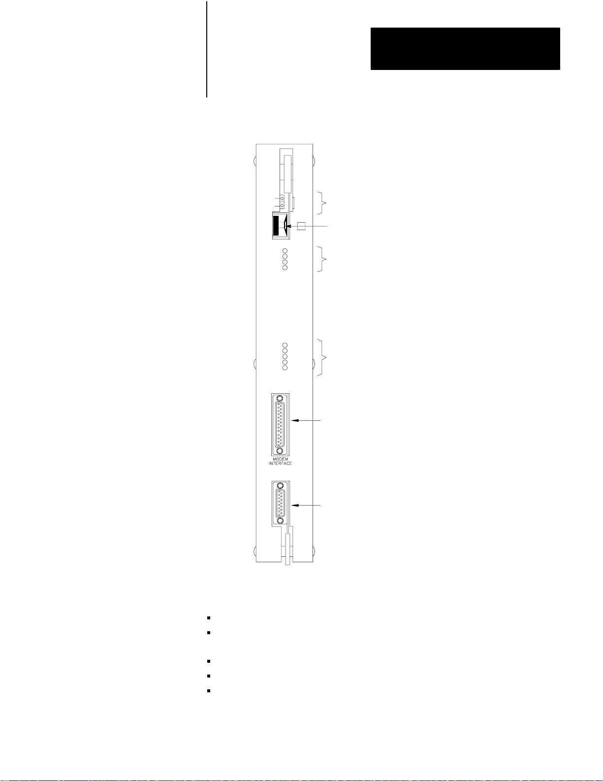
Figure 1.1 illustrates the front of the 1775–KA module. The module has
the following hardware features:
Self–test diagnostic indicators
Thumbwheel switch for setting identification number
Two ports– one for Data Highway and one for RS–232–C
communication
Two sets of indicators – one for each port
Switches for selecting fault responses and communication option
14
Page 9
Chapter 1
Introduction
Figure 1.1
Communication
PASS
FAIL
COMMUNICATION
ADAPTER
Adapter Module (Cat. No. 1775-KA)
KA
XMTG
RCVG
ERR
DIS
MODEM
INTERFACE
XMTG
RCVG
RDY
ERR
DIS
DATA
HWY
SELF
TEST
NO
Self–Test Indicators
Thumbwheel Switch
RS–232–C port Indicators
Data Highway Port Indicators
RS–232–C Port
Data Highway Port
DATA
HWY
10000-I
In addition, the module provides the following software features:
Programmable configuration parameters
Command language that allows for complex logic decisions, looping,
and nesting
Symbolic representation of data and addresses
Embedded arithmetic expressions and logic operations
Decimal, octal, or BCD (binary coded decimal) data entry
15
Page 10

Chapter 1
Introduction
Specifications
Function
Interface the PLC-3 Processor
with the Allen-Bradley Data
Highway and/or with an RS-232-C
device
Location
Single slot in PLC-3 main chassis
or expander chassis
Communication Ports
Data Highway
RS-232-C Modem
Applications
Table 1.C lists the specifications for the 1775–KA module.
Table 1.C
Specifications
Module
Communication Rate
T
o Data Highway - 57.6 kilobaud
recommended
o modem-programmable from 1
T
baud to 19.2 kilobaud
Cabling
o Data Highway-Data Highway
T
dropline cable (Cat.no.1770-CD or
equivalent
T
o modem-Modem interface cable
(cat. no. 1775-CKA or equivalent)
Backplane Power Requirement
2.5A max. @ +5V DC
Ambient T
10
Humidity Rating
emperature Rating
00 o 600C (operational)
0
-40
to
850C (storage)
5% to 95% (without condensation)
As already mentioned, the 1775–KA module serves two main purposes:
Interfacing the PLC–3 processor with the Allen–Bradley Data Highway
Interfacing the PLC–3 processor with an intelligent RS–232–C device
You can use the module for both of these purposes simultaneously.
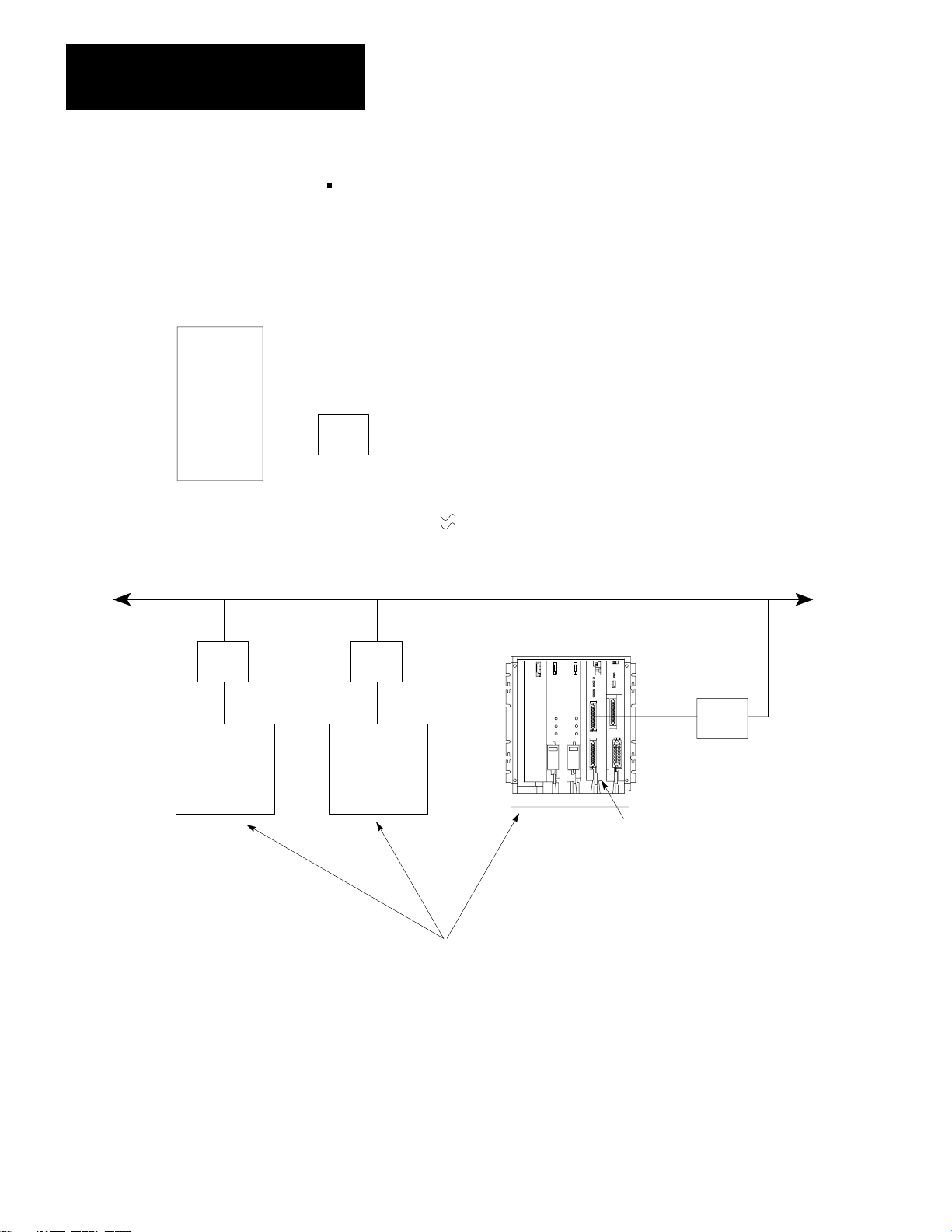
In Data Highway applications, the module serves as an interface between
the PLC–3 programmable controller and the Allen–Bradley Data
Highway. The Data Highway is an industrial communication network
that links together as many as 64 distinct stations. Each station can consist
of a programmable controller (such as the PLC–3), a computer, or an
intelligent RS–232–C device. The central trunkline of the Data Highway
may be up to 10,000 feet long, and each station may be as far as 100 feet
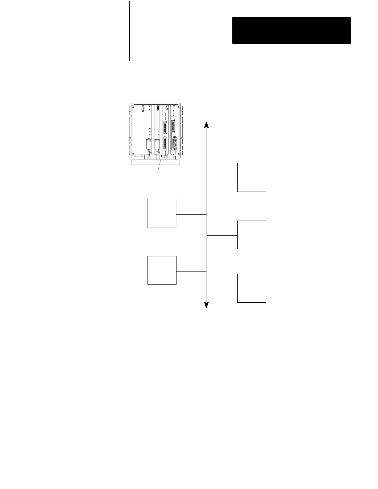
from the trunkline. Figure 1.2 gives an example of a Data Highway
configuration.
16
Page 11
Chapter 1
Introduction
Figure 1.2
Example
PLC-3
Controller
1775-KA
Data Highway Configuration
Allen-Bradley
Data Highway
PC
Module
PC
PC
PC
NOTE: All PCs are Allen-Bradley
PC
Up to 64 Stations
10001–I
17
Page 12
Chapter 1
Introduction
The PLC–3 can support multiple 1775–KA modules in the same PLC–3
chassis. This provides the PLC–3 with concurrent access to several
independent Data Highways.
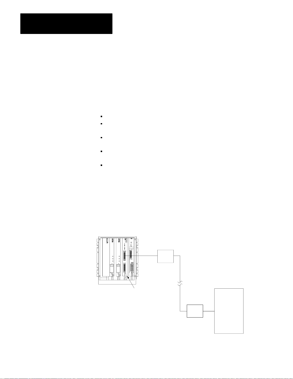
The 1775–KA module can also serve as an interface between the PLC–3
programmable controller and an intelligent RS–232–C compatible device
or any Allen–Bradley PC and its Data Highway module. Some examples
of this application of the module are the following:
Interfacing two PLC–3 controllers through a modem link
Interfacing a PLC–3 controller with a computer (either directly or
through modems)
Interfacing a PLC–3 controller with a remote Data Highway through a
modem link
Interfacing a PLC–3 controller as a slave station on a multipoint
modem link
Interfacing a PLC–3 controller on a point–to–point link with PLC–2
Family processor through a 1771–KG module (The 1772–LR processor
is not supported in this configuration.)
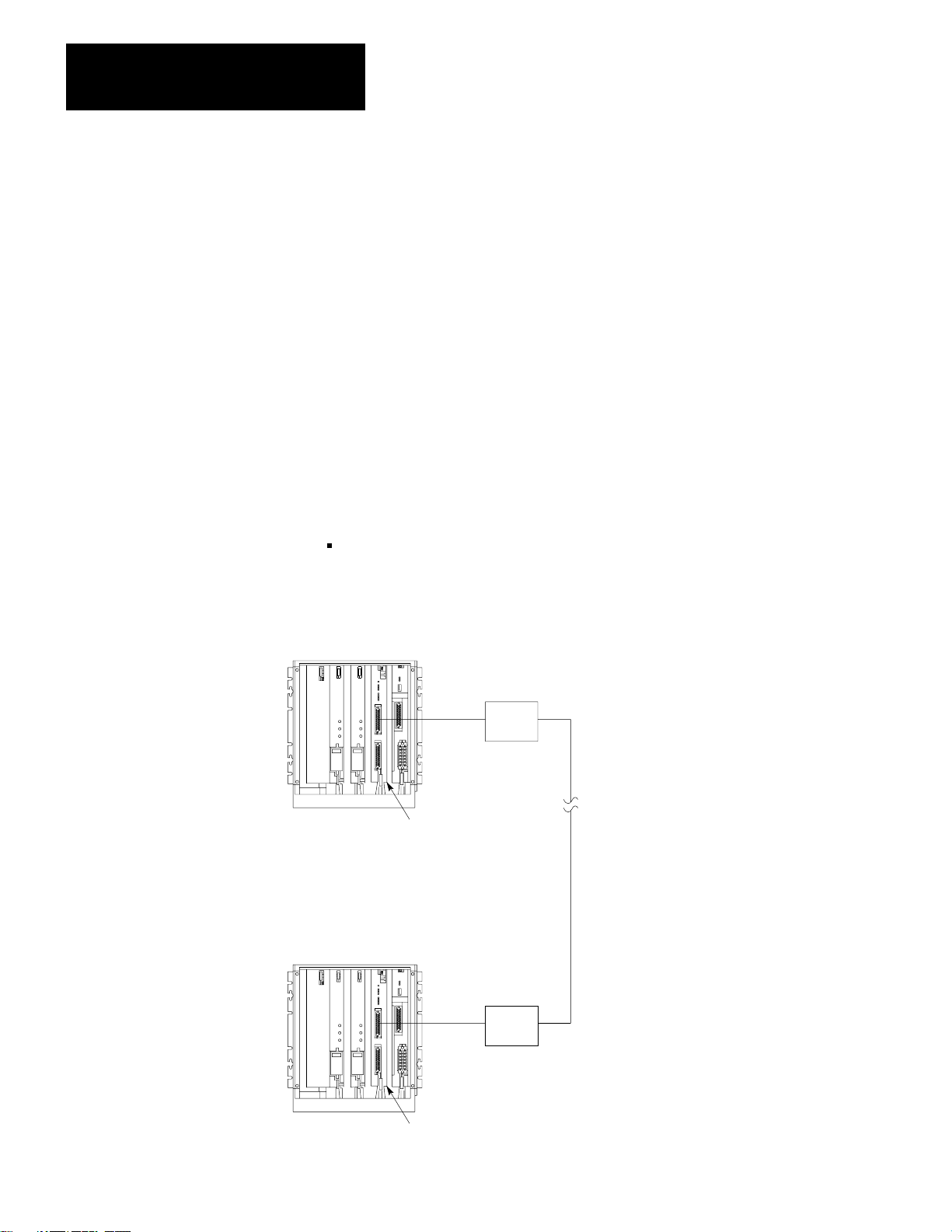
Figure 1.3 shows the 1775–KA module in a typical modem application.
Figure 1.3
Modem Application
Typical
PLC-3
Controller
Modem
Computer
1775-KA
NOTE: Modems required
only
for distances greater
than 50 feet.
Module
Modem
10002–I
18
Page 13

Installation
Chapter
2
General
Hardware Installation
This chapter describes installation of the 1775–KA module in two phases:
Installing hardware
Programming configuration parameters through the PLC–3 LIST
function
Please read the entire manual carefully before attempting to install the
module.
For best results when installing the 1775–KA module, proceed in the
order indicated below.
Switch Settings
The 1775–KA module has a number of hardware switches that must be set
before the module can be installed in the PLC–3 processor. There is a
thumbwheel switch on the front edge of the module and a group of option
switches on the bottom edge.
Thumbwheel Switch
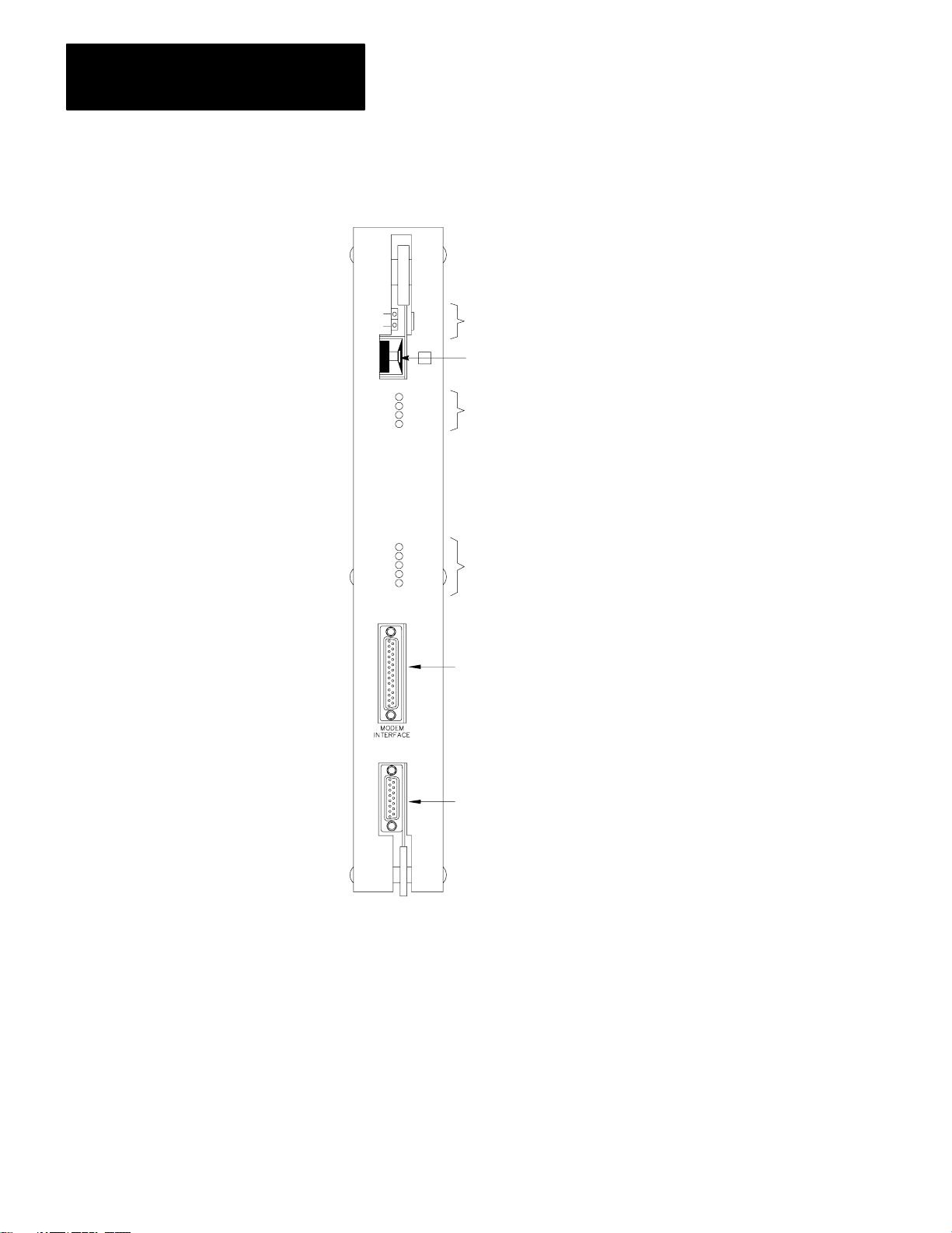
Figure 2.1 shows a thumbwheel switch on the front edge of the 1775–KA
module. This thumbwheel switch designates the number used by the
PLC–3 processor to distinguish one 1775–KA module from another.
Rotate the thumbwheel to select the desired identification number.
21
Page 14
Chapter 2
Installation
Figure 2.1
V
iew of 1775-KA Module
Front
PASS
FAIL
KA
XMTG
RCVG
ERR
DIS
COMMUNICATION
ADAPTER
XMTG
RCVG
RDY
ERR
DIS
MODEM
INTERFACE
DATA
HWY
SELF
TEST
NO
Self–Test Indicators
Thumbwheel Switch
RS–232–C port Indicators
Data Highway Port Indicators
RS–232–C Port
22
Data Highway Port
DATA
HWY
If there is only one 1775–KA module in the PLC–3 chassis, set its
thumbwheel switch to the number 1. If there are multiple 1775–KA
modules in the same PLC–3 chassis, set their thumbwheel switches to
consecutive numbers, starting with the number 1. You may write the
selected number in the space provided beside the thumbwheel switch.
10003-I
Page 15

Chapter 2
Installation
CAUTION: To guard against unpredictable operation of the
PLC–3 processor, do not change the setting on any thumbwheel
switch while the 1775–KA module is powered–up.
Option Switches
Figure 2.2 shows a set of four option switches on the bottom edge of the
1775– KA module. Switches 1 and 2 are used when the PLC–3 controller
is programmed to operate in a backup configuration. Switch number 1
determines whether or not a fault in the 1775–KA module will cause the
primary PLC–3 controller to switch over to the backup PLC–3. Switch
number 2 determines whether or not the 1775–KA module will disable its
Data Highway port when the PLC–3 becomes deactive. Switch 3 is for
RS–232–C communication. Switch 4 is reserved for future use and
should always be left open (up, or off). Use Table 2.A below to determine
the appropriate switch setting:
Figure 2.2
Option
Switches
23
Page 16

Chapter 2
Installation
Table 2.A
1775-KA Switch Settings
If this
switch: Is: Then
1 OPEN
1 CLOSED
2 OPEN
2 CLOSED
the PLC will switch over to backup whenever one of the
following fault conditions occurs:
1. The 1775-KA module tries to hold control of the PLC-3
backplane for more than 138 microseconds.
2.
The 1775-KA module experiences a execution timeout of
more than 32 milliseconds
3.
The 1775-KA module experiences an internal stack
overflow
4.
The 1775-KA module experiences severe Data Highway
communication problems.
the primary PLC-3 will not switch to backup when a fault occurs
with the 1775-KA module.
the 1775-KA module will disable is Data Highway port
whenever the primary PLC-3 controller becomes deactive. The
module will no longer be able to transmit or receivemessages
through its Data Highway port.
Also, setting switch 2 to open enables the backup operation
feature.
the Data Highway port on the module will remain active if the
primary PLC-3 becomes deactive.
24
3 OPEN
3 CLOSED
4 OPEN
the module may be connected up to 7,000 cable feet away from
a 1771-KF
In addition to setting switch 3 to the open position, you must
also set switch 2 to closed position. This makes pin 25 on the
RS-232-C port of the 1775-KA module active (refer to figures
2.8 to 2.10). Note that switch 3 must always be closed for
communication with an RS-232-C device other than a
1771-KF
the MODEM INTERF
connected to a standard RS-232-C device that is located within
50 cable feet of the module.
Switch 4 is reserved for future use and should always be left
open.
, a 1771-KG, 1773-KA or another 1775-KA module.
, 1771-KG, 1773-KA, or 1775-KA module.
ACE port of the 1775-KA module may be
Module Placement
After setting the thumbwheel switch, insert the module into any one of the
module slots in the PLC–3 processor chassis. Whenever you power–up
the processor, the module will receive power also.
Page 17

Chapter 2
Installation
Indicators
There are three sets of LED indicators on the front of the 1775–KA
module (Figure 2.1). The first group, labeled SELF–TEST, indicates the
result of internal diagnostic tests that the module continuously performs
on its own hardware and firmware. The second group, labeled MODEM
INTERFACE, indicates the status of communication through the module’s
RS–232–C port. The last group, labeled DATA HWY, indicates the status
of communication through the module’s Data Highway port.
Table 2.B. tells what each indicator means.
Table 2.B
Indicators
LED
Indicator
Group
Self-Test PASS
Modem
Interface
Data
Highway
Indicator
Label
FAIL
XMTG
RCVG
ERR
DIS
XMTG
RCVG
RDY
ERR
DIS
Normal
State
ON
OFF
OFF
OFF
OFF
OFF
OFF
OFF
ON or
OFF
OFF
OFF
Meaning When ON
Module has passed its own internal diagnostic test
Module has failed its own internal diagnostic tests
Module is transmitting a message over the modem interface port
Module is receiving a message over the modem interface port.
User programming error
Module is disabled due to a fault in the PLC-3 processor, or modem interface
port is disabled through the LIST function
Module is transmitting a message over the Data Highway port
Module is receiving a message over the Data Highway port
[1]
Module is ready to transmit a message over the Data Highway port and is
waiting to acquire mastership of the highway
User programming error or communication error on either the Data Highway or
the Modem port
Module is disabled due to a fault in the PLC-3 processor
is disabled through the LIST function
, or Data Highway port
[1]
Depends
on amount of data highway activity
25
Page 18
Chapter 2
Installation
Data Highway Cable Connections
There are two cable connectors, or ports, on the front of the 1775–KA
module (Figure 2.1). The bottom port, labeled DATA HWY., is for
connection to the Allen–Bradley Data Highway. If you are using the
1775–KA module in a Data Highway application, plug the Data Highway
dropline cable into this port. For details on the installation of the Data
Highway cable, refer to the Data Highway Cable Assembly and
Installation Manual (publication 1770–810).
RS-232-C Cable Connections
The RS–232–C port, labeled MODEM INTERFACE on the 1775–KA
module, can interface with any RS–232–C device that is capable of
understanding and generating the communication protocol described in
this chapter. Some typical RS–232–C applications are:
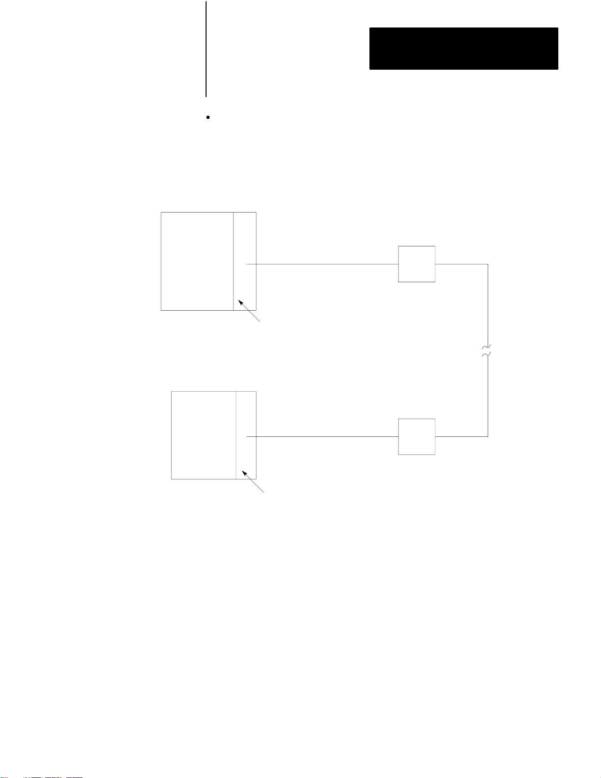
Interfacing two PLC–3 controllers through a modem link (Figure 2.3)
Figure 2.3
Two PLC-3 Controllers
Linking
PLC-3 Controller
Modem
1775-KA
PLC-3 Controller
Module
Modem
26
1775-KA
Module
NOTE: Modems required only
for distances greater
than 50 feet.
10004–I
Page 19
Chapter 2
Installation
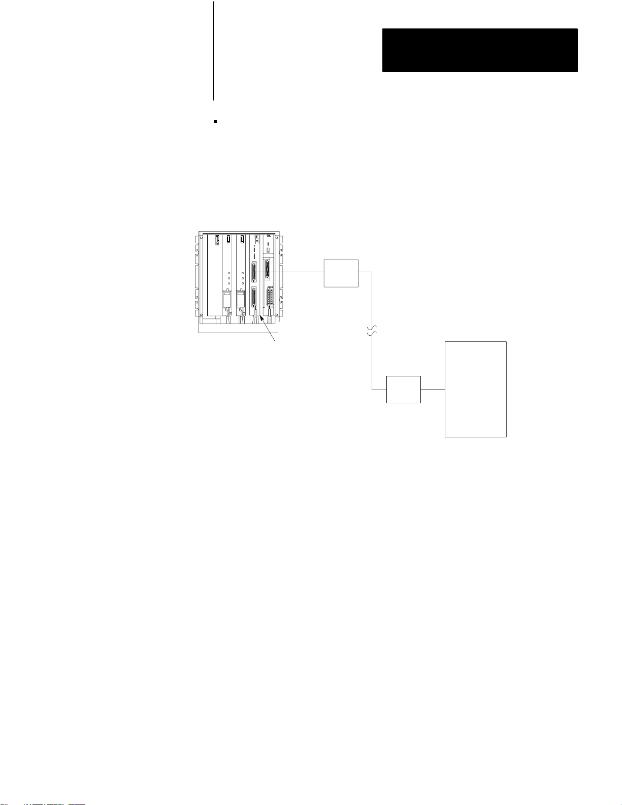
Interfacing a PLC–3 controller with a computer, either directly or
through modems (Figure 2.4)
Figure 2.4
a PLC-3 Station to a Computer
Linking
PLC-3
Controller
Modem
Computer
1775-KA
Module
Modem
10005–I
27
Page 20
Chapter 2
Installation
PLC-3
Controller
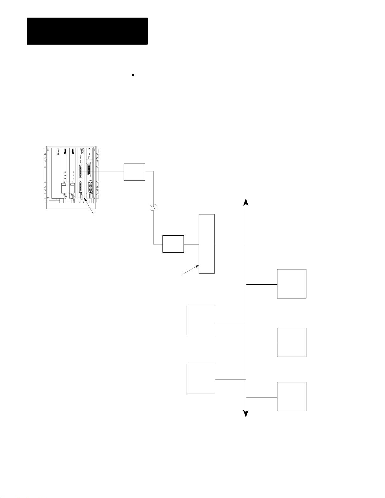
Interfacing a PLC–3 controller with a remote Data Highway through a
modem link (Figure 2.5)
Figure 2.5
a PLC-3 Station to a Remote Data Highway
Linking
Modem
1775-KA
NOTE: All PCs are Allen-Bradley
Module
Modem
1771-KF Module
PC
PC
Allen-Bradley
Data Highway
PC
PC
PC
28
Up to 64 Stations
10006–I
Page 21
Interfacing a PLC–3 controller to a PLC–2 Family processor through a
1771–KG module in a point–to–point link (Figure 2.6)
Figure 2.6
a PLC-3 to PLC-2 Family Controller
Linking
PLC–3 Controller
Chapter 2
Installation
Modem
PLC–2 Controller
1775–KA
1771–KG Module
Module
Modem
NOTE: Modems required only for
distances greater than 50 feet.
10007-I
29
Page 22
Chapter 2
Installation
Computer
Master Station
Interfacing a PLC–3 controller as a slave station on a multipoint
modem link (Figure 2.7)
Figure 2.7
a PLC-3 to a Multi-drop Modem Link
Linking
Multidrop Modem
Multidrop Modem Link
The first four applications above use the module’s RS–232–C port in the
unpolled mode, while the last application uses the polled mode. You can
select the mode of operation and other characteristics of the RS–232–C
port through the LIST function.
Slave Stations
PLC-3 Controller
1775-KA
Modem
Module
10008–I
210
Page 23

Chapter 2
Installation
Each mode of operation requires a different communication protocol. The
unpolled mode uses full–duplex protocol (chapter 10) while the polled
mode uses half–duplex protocol (chapter 11). In general, full–duplex
protocol gives faster data throughput but is more difficult to implement;
half–duplex protocol is easier to implement but gives slow data
throughput.
NOTE: In other Data Highway documentation, full–duplex protocol
might be referred to as DFI protocol, and half–duplex protocol might be
referred to as polled–mode protocol.
Hardware Interface
The modem interface is based on EIA RS–232–C and related standards.
This interface should be compatible with most dedicated and dial–up
network RS–232 modems.
Mechanical
The RS–232 connector on the 1775–KA module is a 25–pin male
connector.
Electrical
Input and output levels on the RS–232 connector conform to the
RS–232–C standard. The transmitter has increased capability to drive a
7,000 foot isolated lines. This number depends on baud rate and refers to
only direct wire connections. (Refer to Table 2.C.)
211
Page 24

Chapter 2
Installation
Table 2.C
Distance
Rate V
ariations
Distance
in feet
1,000 19,200
2,000 9,600
3,000 9,600
4,000 4,800
5,000 4,800
6,000 2,400
7,000 2,400
Maximum
Baud Rate
The receiver is designed to sense the signal generated by a similar
transmitter, and is electrically isolated from all other circuitry on the
module. It consists of an opto–isolater circuit with an input and return
connection at the RS–232 connector. All other signals on the RS–232
connector are driven and received by standard RS–232 interface circuits,
and have a maximum drive capability of 50 feet.
212
Page 25
Chapter 2
Installation
Pinout
The necessary RS–232–C port connections are described in Table 2.D
below:
Table 2.D
RS-232-C
Port Connections
Signal at the
1775-KA Abbreviation Pin Input/Output
chassis/shield drain
transmitted data
received data
request to send
clear to send
data set ready
transmitted data return
data carrier detect
data terminal ready
received data return
1
TXD 2 Output
RXD 3 Input
RTS 4 Output
CTS 5 Input
DSR 6 Input
TXDRET 7/14
DCD 8 Input
DTR 20/11 Output
RXDRET 25/13
TXD (transmitted data) caries serialized data. It is output from the
RS–232 connector.
RXD (received data) is serialized data input to the RS–232 connector.
RXD and RXDRET are isolated from the rest of the circuitry on the
module.
RTS (request to send) is a request from the RS–232 connector to the
modem to prepare to transmit. It typically turns the data carrier on.
When you select the full duplex mode RTS is always asserted. When
you select the half duplex mode RTS is turned on when the module has
permission to transmit; otherwise it is off.
CTS (clear to send) is a signal from the modem to the RS–232
connector that the carrier is stable and the modem is ready to transmit.
The module will not transmit until CTS is true. If CTS is turned off
during transmission, the module will stop sending until CTS is restored.
DTR (data terminal ready) is a signal from the RS–232 connector to the
modem to connect to the phone line (that is, “pick up the phone”). The
module will assert DTR all the time except during the phone hangup
213
Page 26

Chapter 2
Installation
sequence. Some modem will not respond to DTR until the phone rings,
while others will always pick up the phone whether it is ringing or not.
DSR (data set ready) is a signal from the modem to the RS–232
connector that the phone is off–hook. (It is the modem’s answer to
DTR). The module will not transmit or receive unless DSR is true. If
the modem does not properly control DSR, or if no modem is used,
DSR must be jumpered to an RS–232 high signal at the RS–232
connector. (It can be jumpered to DTR).
DCD (data clear ready) is a signal from the modem to the RS–232
connector that the carrier from another modem is being sensed on the
phone line. It will not be asserted unless the phone is off–hook. Data
will not be received at the RS– 232 connector unless DCD is true. In
the full duplex mode the module will not transmit unless DCD is true.
If the modem does not properly control DCD, or if a modem is not
being used, DCD must be jumpered to DTR at the RS–232 connector.
TXDRET (transmitted data return) is the return signal for TXD. It is
connected to module logic ground through a resistor.
RXDRET (received data return) is the return signal for RXD. It is
connected to the isolated receiver, and is isolated from all other
circuitry on the module.
Connections To The RS–232 Port
Connection to the RS–232 port of the 1775–KA can be one of two types:
Short line (50 feet or less)
Isolated long line (between 50 and 7,000 feet)
For short lines, the connection may be either direct or through modems.
You connect an intelligent, RS–232–C compatible device to an interface
module by attaching a cable to both the device and to the module socket
labeled RS– 232–C CHANNEL. The RS–232–C device may be another
Allen–Bradley communication interface module or another
manufacturer’s device. For a standard RS–232–C connection, the cable
should be no longer than 50 feet. If your RS–232–C device has an
Allen–Bradley line driver/receiver, you may use a cable up to 7,000 feet
long.
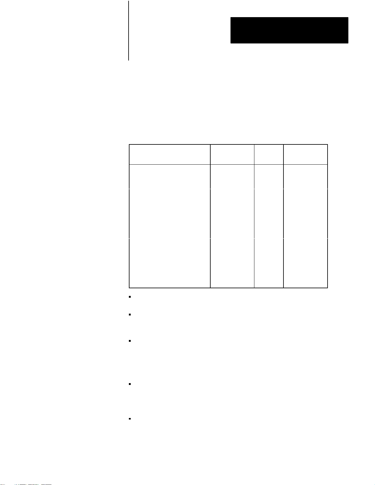
If you want to connect the 1775–KA module to a 1771–KG or
1771–KE/KF module through the RS–232–C channel, use the cabling
pinout diagram (Figure 2.8) to construct your own cable.
214
Page 27
Chapter 2
Installation
RS–232–C
CHANNEL
Connector
of 1775–KA
Module
1
2
Figure 2.8
Connection
1
2
7
3
25
4
5
6
8
20
to Allen-Bradley 1771-KG or 1771-KE/KF Module
Connect the Shield at One End Only
13
14
11
1
3
RS–232–C
CHANNEL
Connector
2
4
5
6
8
of 1771–KG
or 1771–KE/KF
Module
1
Conductors 2 and 7, 3 and 25 must be twisted pairs for distances longer
than 50 feet.
2
Set switch 3 (on the 1775–KA) OFF when the module is communicating
with another Allen-Bradley device.
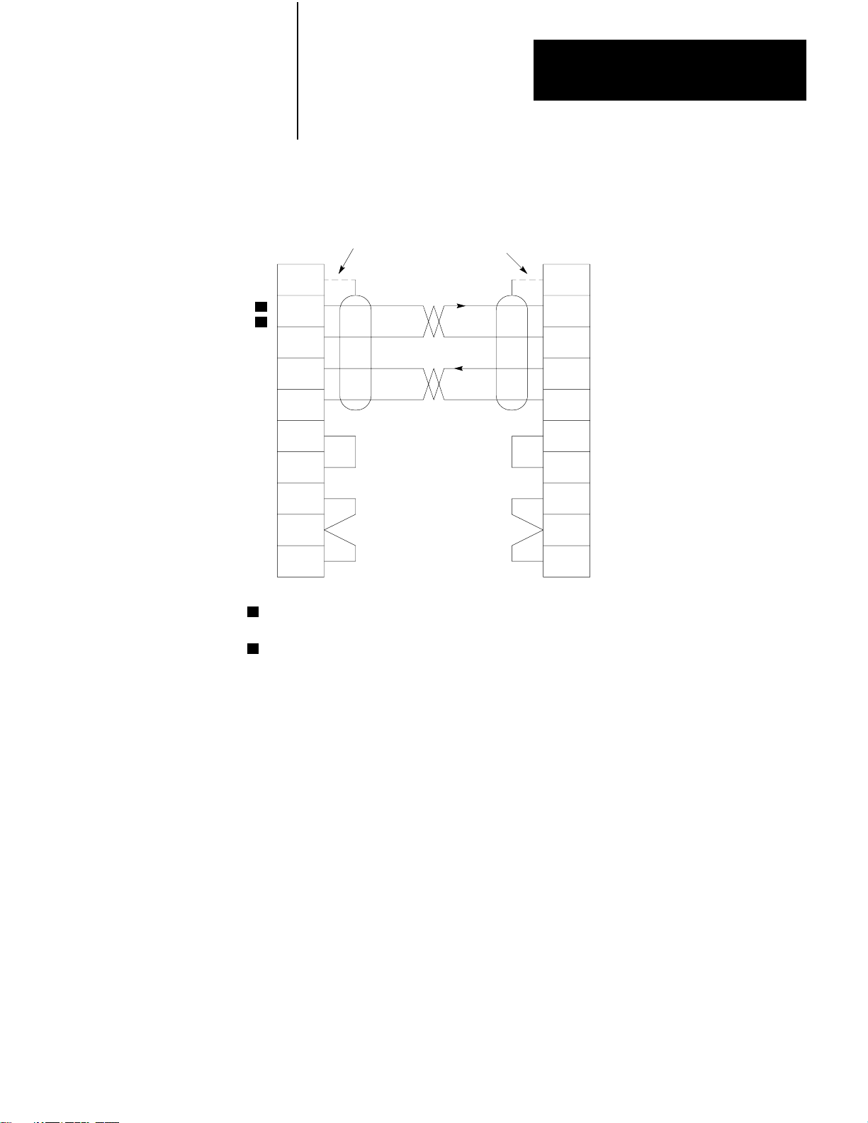
If you want to connect the 1775–KA module to a 1775–KA module
through the RS– 232–C channel, use the cabling pinout diagram
(Figure 2.9) to construct your own cable.
10009–I
215
Page 28
Chapter 2
Installation
RS–232–C
CHANNEL
Connector
of 1775–KA
Module
Figure 2.9
Connection
1
1
2
2
7
3
25
4
5
6
8
20
1
Conductors 2 and 7, 3 and 25 must be twisted pairs for distances longer
than 50 feet.
2
Set switch 3 (on the 1775–KA) OFF when the module is communicating
with another Allen-Bradley device.
to Allen-Bradley 1775-KA Module
Connect the Shield at One End Only
25
20
1
3
RS–232–C
CHANNEL
Connector
2
7
4
5
6
8
of 1771–KA
Module
10010–I
216
If you want to connect the 1775–KA module to a modem or computer, use
the cabling pinout diagram (Figure 2.10) to construct your own cable.
Page 29
Chapter 2
Installation
Figure 2.10
Connection
RS–232–C
CHANNEL Connector of
1775–KA
Protective Ground
Transmitted Data
Received Data
Request to Send
Clear to Send
Data Set Ready
Signal Ground
Line Signal Detect
Data Terminal Ready
Received Data
Return
1
Module
to user-Supplied Modem or RS-232-C Device
1
2
3
4
5
6
7
8
20
25
1
Set Switch 3 ON to ground pin 25.
User–supplied
Moderm or
RS–232–C
Device
10011–I
Private lines are permanently connected phone lines used with modems.
Dialup is not needed. Usually the modem hold the handshake lines in the
proper states.
The RS–232 port can be connected to standard American dial–up modems
and some European modems. Other European standards specify that the
DTR signal will cause the modem to answer the phone whether it is
ringing or not, causing the phone to always be “busy”. Since the modem
port asserts DTR while waiting for a call, it cannot be used with such
modems.
The types of dial–up network modems that can be used are classified into
the following types:
Manual: these are typically acoustically coupled modems. The
connection is established by human operators at both ends, who then
insert the handset into couplers to connect the computers.
DTE–controlled answer: these unattended modems are directly
connected to the phone lines. A module controls the modem via the
217
Page 30

Chapter 2
Installation
DTR, DSR, and DCD signals. It incorporates timeouts and tests to
properly operate these types of modems.
Auto–answer: these modems have self–contained timeouts and tests,
and can answer and hangup the phone automatically.
The modem port has no means to control an auto–dial modem, although it
is possible that it can be used in conjunction with a separate auto–dialer.
Answering
The module continually asserts DTR when it is waiting for a call. Under
this condition the modem will answer a call and assert DSR as soon as
ringing is detected. The module does not monitor the RING indicator in
the RS–232 interface. Once DSR is detected the module starts a timer
(around 10 seconds) and waits for the DCD signal. When DCD is
detected communication can start.
If DCD is not detected within the timeout, the module turns DTR off. This
causes the modem to hangup and break the connection. When the hangup
is complete the modem drops the DSR line. This causes the module to
reassert the DTR line and wait for another call. This feature protects
access to the phone if someone calling a wrong number reaches this
station.
Once DCD is detected the module continues to monitor the DCD line. If
DCD goes false the timeout is restarted. If DCD is not restored within the
timeout, the hangup sequence is initiated. This feature allows the remote
station to re–dial in the event the connection is lost by the phone network.
Note that this handshaking is necessary to guarantee access to the phone
line. If this handshaking protocol is defeated by improper selection of
modem options, or jumpers at the connectors, the modem may answer a
call, but if the connection is lost the modem will not hangup. It will be
impossible for the remote station to reestablish the connection because it
will get a busy signal.
Character Transmission
218
Data is sent serially over the RS–232 interface, one eight–bit byte at a
time. The transmission format conforms to ANSI X3.16, CCITT V.4, and
ISO 1177, with the exception that the parity bit is retained while
extending the data length to eight bits.
Page 31

Chapter 2
Installation
The transmission format may be summarized as follows:
start bit
data bit 0
data bit 1
data bit 2
data bit 3
data bit 4
data bit 5
data bit 6
data bit 7
even parity bit (optional)
one stop bit
The 1775–KA module selects baud and parity through the LIST function
(section titled Programmable Configuration Parameters).
Programmable Configuration Parameters
A number of installation parameters for the 1775–KA module can be
programmed through the PLC–3 LIST function.
The LIST function words by presenting you with a series of lists, or
menus, that allows you to select and establish the module’s operating
parameters. Each option in an upper–level menu represents a submenu of
more detailed options. This process continues until you have selected
enough options to define a single parameter in full detail. Figure 2.11
illustrates the menu structure of LIST. To return to the preceding (next
highest) level of LIST, press the ENTER key without making a new entry.
219
Page 32

Chapter 2
Installation
Figure 2.11
Menu for 1775-KA Module
LIST
System Mode
1
Test–Monitor
2 Run Monitor
3 Program Load
4 Remote Enable
5 System Status
6 *Module Status
Enter Next >
Modules
1 01
1775–ME8
1775–ME8
2 02
3 03
1775–L3
4 04
1775–S4A
5 05
1775–KA A/E
6 06
1775–LX
7 07
1775–LX
8 08
1775–S4B B/A
9 09
1775–S4B B/A
ENTER NEXT
A/A
A/A
A/A
B/A
A/A
A/A
>
Data Hwy Comm
Adapter – 01
Chassis 0 Slot 0
1 Module Options
2 Data Highway Port
3 Modem Port
Enter Next >
KA–01 Module Options
1
Timeout
2 *Send Unprotected
3
Accept Upload/Download
4
Accept W
5 Backup Operation
6 PLC–2 Mask
ENTER NEXT
KA–01 Data Highway Port
1 Enable/Disable Port
2 Station Number
3 Baud Rate
Enter Next >
rites
1
1
1
1
>
KA–01 Module Options
1
Timeout
Enter Timeout >
KA–01 Data Highway Port Enable
1 Enable
2 *Disable
Enter Next >
KA–01 Data Highway Port
Station Number
Enter Station Number >
KA–01 Data Highway Port Baud Rate
1 38400
2 *57600
Enter Next >
= 50/10 sec
= 377
220
KA–01 Modem Port
1 Enable/Disable Port
2 Station Number
3 Baud Rate
4 Communication Mode
5 Even Parity
6 *Send Embedded
Responses
Enter Next >
1
T
oggle selection – select this number to enable
or disable the option.
NOTE: Those selections shown in bold type affect
the operation of the module; the LIST
display
shows an asterisk (*) to indicate when an
option is enabled.
The selections not shown in
bold type only cause a movement to another level
of LIST
.
This selections indicated in this figure are
selected by default at the initial power–up.
KA–01 Modem Port Enable
1 Enable
2 *Disable
1
1
Enter Next >
KA–01 Modem Port
Station – 377
Enter Station Number >
KA–01 Modem Port Baud Rate
1 1
10
2 300
3 600
4 *1200
5 2400
6 4800
7 9600
8 19200
Enter Next >
KA–01 Modem Port Communication Mode
1 *Unpolled Mode
2 Polled – Subscriber Mode
Enter Next >
10012–I
Page 33

Chapter 2
Installation
You access the LIST function by typing the word LIST and press the
ENTER key. After accessing the LIST function, select option 6 MODULE
STATUS from the SYSTEM–MODE MENU. LIST then presents you
with a menu that describes the modules in your system. The menu varies
according to the modules in your PLC–3. A typical menu might be:
MODULES:
1 01 1775–ME8 A/A
2 02 1775–ME8 A/A
3 03 1775–L3 A/A
4 04 1775–S4A B/A
5 05 1775–KA A/E
6 06 1775–LX A/A
7 07 1775–LX A/A
8 08 1775–S4B B/A
9 09 1775–S4B B/A
ENTER NEXT<
Under MODULE STATUS, select the option for 1775–KA. At this point,
LIST presents you with the following menu for the 1775–KA module:
DATA HWY COMM. ADAPTER–nn
CHASSIS cc SLOT ss
1 MODULE OPTIONS
2 DATA HIGHWAY PORT
3 MODEM PORT
ENTER NEXT>
In the above and all following menus, “nn” represents the thumbwheel
setting of the 1775–KA module, “cc” represents the chassis number, and
“ss” represents the number of the chassis slot containing the module. For
more information about the LIST function, refer to Publication 1775–800,
PLC–3 Installation and Operation Manual.
Module Options
Selecting option 1 MODULE OPTIONS from the above menu (section
titled Programmable Configuration Parameters) causes LIST to present
the following menu:
KA – nn MODULE OPTIONS
1 TIMEOUT
2 SEND UNPROTECTED
221
Page 34

Chapter 2
Installation
3 ACCEPT UPLOAD/DOWNLOAD
4 ACCEPT WRITES
5 BACKUP OPERATION
6 PLC–2 MASK
ENTER NEXT>
This menu allows you to select options that apply equally to both the
modem port and the Data Highway port of the 1775–KA module. These
options are described below.
Timeout
The timeout is the maximum amount of time that the 1775–KA module
will wait for another station to reply to one of its messages. The allowed
entries are 0 to 9999, expressed in increments of 1/10 second. LIST
displays the timeout as “xxxx/10 SEC”. Thus, if you enter a timeout
value of 100, the timeout period will be 10 seconds and will be displayed
as 100/10 SEC.
The same timeout setting applies to both the Data Highway and the
modem ports. The default timeout setting is 5 seconds, displayed as 50/10
SEC.
The timeout period applies to each individual transmission. Because of
their size, some messages consist of several packets of data. Each
message packet requires a separate transmission. Therefore, the timeout
is restarted for each packet.
If the 1775–KA module waits longer than the timeout period for a reply to
one of its messages, it generates an error code of 37 (Appendix B). The
module then resumes executing the current message procedure at the line
following the one in which the timeout occurred.
LIST keeps you at this timeout level and allows you to make repeated
changes to the timeout value. To return to the preceding (next highest)
level of LIST, press the ENTER key again without entering a new timeout
value.
222
Page 35

Chapter 2
Installation
Send Unprotected
This option determines whether or not the 1775–KA module will be able
to send unprotected command messages to other stations. If you select
option 2 SEND UNPROTECTED, the 1775–KA module will be able to
send both protected and unprotected commands.
You can use an unprotected command to read or write to any area of a PC
data table. You can use a protected command, however, to write only to
those areas of a PC data table specified by the PC that receives the
command. For more information on protected and unprotected
commands, see section titled Access Privileges, chapter 3.
If you do not select (enable) this option, the module will be able to
transmit only protected commands. At initial power–up, the module
enables the SEND UNPROTECTED option by default.
Accept Upload/Download
This option determines whether or not the 1775–KA module will be able
to execute upload and download commands sent to it by a computer. If
option 3 ACCEPT UPLOAD/DOWNLOAD is selected, the module will
be able to execute both upload and download commands. You send a
sequence of upload and download commands when you want to transfer
the memory of the PLC–3 to another station, or to transfer the memory of
another station to a PLC–3.
If this option is not selected (enabled) the module will not be able to
execute either of these two types of commands. For a description of
upload and download commands, refer to Appendix A. At initial
power–up, the module enables the ACCEPT UPLOAD/DOWNLOAD
option by default.
Accept Writes
This option determines whether or not the 1775–KA module will accept
write–type command messages from a remote Data Highway station when
the local PLC–3 processor’s memory protect keyswitch is on. If option 4
ACCEPT WRITES is selected, the module will accept write commands
regardless of the setting of the PLC–3’s memory protect keyswitch. If
this option is not selected (enabled) the module will accept write
commands when the memory protect keyswitch is off but will reject the
write commands and return an error code of 86 if the memory protect
223
Page 36

Chapter 2
Installation
keyswitch is on. At initial power–up, the module enables the ACCEPT
WRITES option by default.
Backup Operation
This option determines whether or not a pair of 1775–KA modules will
provide backup for each other. Enable option 5 (BACKUP OPERATION)
for both the primary and backup 1775–KA modules to enable backup
operation as described in section 2.3 (backup configurations). If you
make no selection for option 5, backup operation is disabled by default.
The revision C or earlier version of the module does not have the
BACKUP OPERATION option.
PLC–2 Mask
This option determines whether or not the 1775–KA module will mask
out the upper octal digit of the source address when receiving a PLC–2
type command from another station. If you enable option 6
(PLC–2–MASK) the module mask out the upper digit of the address for
selecting the input file. This causes stations with common second and
third digits of their address to access the same input file. For example,
stations 023, 123, 223, and 323 would all access input file 023.
If you disable option 6, each station accesses a unique input file with the
same number as the station number. For example, station 123 would
access input file 123; station 223 would access input file 223. If you
make no selection for option 6, the PLC–2 MASK option is disabled by
default. The revision D or earlier version of the module does not have the
PLC–2 MASK option.
Data Highway Port
Selecting option 2 DATA HIGHWAY PORT from the above menu
(section titled Programmable Configuration Parameters) causes LIST to
present the following menu:
224
KA – nn DATA HIGHWAY PORT
1 ENABLE/DISABLE PORT
2 STATION NUMBER
3 BAUD RATE
ENTER NEXT>
Page 37

Chapter 2
Installation
This menu allows you to select options that apply to only the Data
Highway port of the 1775–KA module. These options are described
below.
Enable/Disable Port
This option determines whether or not the 1775–KA module can
communicate over the Data Highway. you must select the ENABLE
option in order to allow communication to take place. If you make no
selection, the PLC–3 disables this port by default.
Note, however, that you cannot use LIST to change any other parameters
of the Data Highway port unless you first DISABLE the port. After you
are done entering parameters through LIST, don’t forget to ENABLE the
Data Highway port again.
Station Number
This option selects the number by which the PLC–3 station is identified
on the Data Highway. Allowable station numbers are 1 to 376 octal. In
particular, note that the number 377 is illegal. Entering 377 as the station
number will automatically disable the 1775–KA module, and you will not
be able to ENABLE it again through LIST until you select a different
station number. If you make no selection, the PLC–3 assumes the illegal
address 377 by default.
Baud Rate
This option specifies the communication rate over the Data Highway. A
communication rate of 57,600 baud is recommended.
Modem Port
Selecting option 3 MODEM PORT from the above menu (section titled
Programmable Configuration Parameters) causes LIST to present the
following menu:
KA–NN modem port
1 ENABLE/DISABLE PORT
2 STATION NUMBER
3 BAUD RATE
4 COMMUNICATION MODE
225
Page 38

Chapter 2
Installation
5 EVEN PARITY
6 SEND EMBEDDED RESPONSES
ENTER NEXT>
This menu allows you to select options that apply to only the modem port
of the 1775–KA module. These options are described below.
Enable/Disable Port
This option determines whether or not the 1775–KA module can
communicate through its RS–232–C port. You must select the ENABLE
option in order to allow this communication to take place. If you make no
selection, the PLC–3 disables the RS–232–C port by default.
Note, however, that you cannot use LIST to change any other parameters
of the RS–232–C port unless you first disable the port. After you are
done entering parameters through LIST, don’t forget to enable the
RS–232–C port again
Station Number
This option selects the number by which the PLC–3 station is identified
on an RS–232–C communication link. In particular, note that the number
377 is illegal. Entering 377 as the station number will automatically
disable the RS– 232–C port of the 1775–KA module, and you will not be
able to enable it again through LIST until you select a different station
number. If you make no selection, the station number will be 377 by
default.
Baud Rate
This option specifies the communication rate over the RS–232–C port.
The choices are:
110 baud 2400 baud
300 baud 4800 baud
600 baud 9600 baud
1200 baud 19200 baud
226
For long–line communication, the maximum allowed rate is 4800 baud.
The default baud rate is 1200 baud (see Table 2.D).
Page 39

Chapter 2
Installation
Communication Mode
This option determines whether the RS–232–C port of the 1775–KA
module can operate in a half–duplex (polled) or full–duplex (unpolled)
mode. Select full– duplex for point–to–point communication through the
RS–232–C port. Select half–duplex if the 1775–KA module is installed
as a slave station on a multipoint modem link. If you make no selection,
the 1775–KA selects the full– duplex (unpolled) mode by default.
Even Parity
This option determines what kind of parity check is used for all
communications through the RS–232–C port. If option 5 EVEN PARITY
is selected, the 1775–KA module will test for even parity in all
communications through its RS–232–C port. If this option is not
selected, the module will not perform any parity checking. At power–up,
the PLC–3 disables the even parity option by default.
Backup Configurations
Send Embedded Responses
This option determines whether or not the 1775–KA module will be able
to send embedded responses through its RS–232–C port. Responses are
acknowledgments (ACKs or NAKs) to messages received from other
stations. An embedded response is one whose characters are transmitted
between the bytes of a regular message. In this way, the response to a
previously received message is transmitted along with a new message. At
power–up, the PLC–3 disables the embedded responses option by default.
The 1775–KA module can combine with the PLC–3 processor to form a
backup system. System backup is described in greater detail in the
PLC–3 Programmable Controller Backup Concepts Manual (pub. no.
1775–6.3.1). The following discussion is an overview of system backup
and the role of the 1775–KA in various backup procedures.
There are two possible backup configurations for the 1775–KA module:
Two 1775–KA modules in the same PLC–3 controller
One 1775–KA module in a primary PLC–3 controller and another
1775–KA in a backup PLC–3 controller
The first configuration provides backup for the 1775–KA module itself.
Here, both 1775–KA modules are always active, and both are independent
stations on their communication network. Therefore, each 1775–KA
227
Page 40

Chapter 2
Installation
module must have its own unique station number. If you want to send the
same message through both 1775– KA modules, you must program the
two separate message instructions.
The second configuration provides system backup for the PLC–3
controller.
If the 1775–KA modules are Rev. C or earlier, you:
1. Assign different station addresses to each communication adapter
module.
2. If the programs in the primary and backup processors are identical:
you must be sure that all information sent to the primary processor is
also sent to the backup processor.
you must examine the run/backup bit (data table status section, file 0,
word 3, bit 17) on every rung used to transmit data. This bit is set in
the primary processor and reset in the backup processor. Examining it
helps to prevent sending duplicate messages over the Data Highway.
If the 1775–KA modules are Rev. D or later, you can:
follow the two steps described above
or
select BACKUP OPERATION with the PLC–3 LIST function.
To implement backup operation, follow these steps:
1. Using the option switches on both 1775–KA modules, set switch 2 to
the OPEN position. Recall (section titled Option Switches) that this
causes the module to disable its Data Highway port if the PLC–3
becomes deactivated.
WARNING: If you do not set these switches OPEN on both
1775–KA modules, these modules will assume the same station
address when the primary PLC–3 becomes deactive. This may
shut down communication on the Data Highway, and
unexpected machine motion may result.
228
Page 41

Chapter 2
Installation
2. Use the LIST function to disable the modem and Data Highway
ports.
3. Use the LIST function to select BACKUP OPERATION for both the
primary and backup 1775–KA modules. For more information, see
the PLC–3 Installation and Operation manual (publication
1775–6.7.1). Thus, when you select BACKUP OPERATION, the
condition appears like this:
5*BACKUP OPERATION
4. Use the LIST function to assign the same station address to the
modules for the primary PLC–3 and the backup PLC–3 processor.
You can never give the 1775–KA module a station address of 3778,
and when you select the BACKUP OPERATION, you can not give
the module an address of 2778.
Because you have chosen BACKUP OPERATION, the module in the
backup PLC–3 will assume an address other than the address you
assign it with the LIST function (Figure 2.12).
You assign both modules an identical address.
If
the address
is between:
0018 and 276
3008 and 376
8
8
The backup module assumes
an address that is:
1008 higher than the primary module
2008 lower than the primary module
At switchover, the address for the backup module returns to the
station address you assigned to it with the LIST function.
5. Use the LIST function to enable whichever (Data Highway or
Modem) port you are using to connect primary to backup.
229
Page 42

Chapter 2
Installation
Figure 2.12
addresses of the primary and backup PLC-3 controllers change during switchover
How
Before switchover: Primary PCL–3 Backup PLC–3
You set these
station addresses: 010
The module assume
the station addresses:
010
010
110
.
After switchover:
You previously set
these station addresses: 010
The module assume
the station addresses:
Backup PLC–3
110
Primary PCL–3
010
010
10013–I
230
Page 43

Chapter 2
Installation
Using Manual Switchover
After you select the BACKUP OPERATION for a rev. D. (or later)
1775–KA module, you may choose to use your PLC–3 backup system for
manual switchover. In manual switchover, you must initiate the
switchover by changing the position of a switch in a backup cable. (Refer
to the PLC–3 Programmable Controller Backup Concepts Manual, pub.
1775–803, for more details.) You must be sure to turn off the faulted
PLC–3 processor before you begin the switchover, however.
If
a manual switchover occurs:
And: Then:
the PLC-3 processor is waiting for a
response
another station on the Data Highway is
initiating a message
you are only communicating with the
primary PLC-3
the response is ignored
you may not receive a response from
either PLC-3 processor
program other stations on the Data
Highway to recover from this condition
the other stations on the Data Highway
will receive time-out errors for
messages they send after the primary
goes deactive and before switchover
occurs.
. Y
ou must
You can program the MSG instruction to execute a message upon
switchover or you can send commands to the backup PLC–3 processor
(Figure 2.13). As long as you get responses from the backup processor,
switchover has not yet occurred.
231
Page 44
Chapter 2
Installation
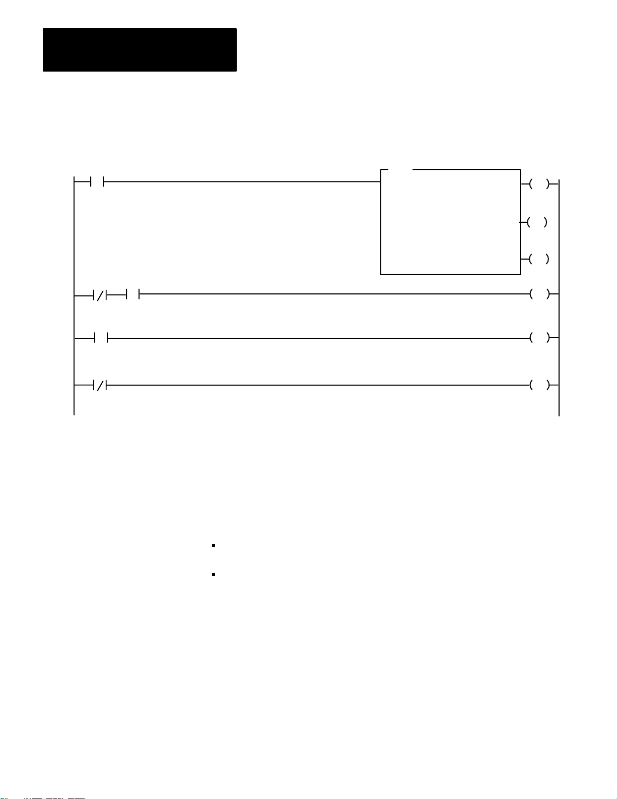
E0000
00
E0000
01
E0000
00
S0003
17
S0003
17
NOTE:
Figure 2.13
Example
PLC-3.
Bits E0000/00 and E0000/01 are internal storage bits. You can use any unused data
table section to reference these bits. Bit S0003/17 is the run/backup bit.
of a Rung that Sends a Message during switchover from primary PLC-3 to backup
MSG
MESSAGE TYPE
CTL = FB200:00001 = 0
CHANNEL: E2.5.
#H045$N4:17= $B3:5
STAT
1
EN
12
STAT
DN
15
STAT
ER
13
E0000
00
E0000
L
01
E0000
U
01
Using Automatic Switchover
After you select the BACKUP OPERATION for a rev. D. (or later)
1775–KA module, you may want to use automatic switchover for your
PLC–3 backup system. During automatic switchover:
the 1775–KA module for the primary PLC–3 processor disables its
Data Highway port.
the 1775–KA module for the backup PLC–3 processor becomes the
address that you selected with the LIST function (rather than the
corresponding address it received during the BACKUP OPERATION).
NOTE: You cannot select the BACKUP OPERATION for a multidrop
modem applications because the modem port will not become disabled
after a PLC–3 processor fault regardless of the switch settings on the
module.
232
Page 45

If
an automatic switchover occurs:
And: Then:
Chapter 2
Installation
the PLC-3 processor is waiting for a
response
another station on the Data Highway is
initiating a message
another station is communicating with
the primary PCL-3 processor
the response is ignored
possibly neither of the PLC-3 processors will
respond to the message. Y
other stations on the Data Highway to recover
from this condition
the other station will receive no indication that
a switchover has occurred. Y
however
execute a message upon switchover (fig.
2.13) or send commands to the backup
PLC-3 processor
communicate with the backup, you know that
no switchover has occurred
, program a MSG instruction to
. If you are able to
ou must program
ou can,
Run/Backup Bit
It is important to alert the proper personnel when a switchover occurs.
One way you can provide such indication is by having your program
monitor the run/backup bit (data table status section, file 0, word 3, bit 17)
and turn on alarms or lights when the status changes from backup to run.
This bit is set in the primary processor and reset in the backup processor.
Multiple 1775-KA Modules in
One PLC-3
It is also possible to link a single PLC–3 controller to more than one Data
Highway by installing multiple 1775–KA modules in the same PLC–3. In
this configuration, each 1775–KA module connects to a different Data
Highway, and each has a unique station number on its associated highway.
However, all the 1775–KA modules in the same PLC–3 controller can
have either the same or different station numbers.
CAUTION: If such a PLC–3 station is communicating through
a PLC/PLC–2 buffer file and all of the stations’ 1775–KA
modules have the same station number, then all of these
modules will transfer data through the same buffer file. This
can cause unpredictable results if several 1775–KA modules try
to read or write to the buffer file at the same time.
When such a PLC–3 station transmits a command message to a remote
Data Highway station, the thumbwheel number specified in the PLC–3
message instruction (section titled PLC–3 Stations) determines which
1775–KA module actually transmits the command.
233
Page 46

Chapter
Data Highway Communication
3
General
Some Terminology
This chapter introduces some of the concepts and terminology involved
with operating the 1775–KA module of the Data Highway.
The Allen Bradley Data Highway is a communication network for
industrial control applications. The Data Highway consists of a central
trunkline cable that may be up to 10,000 feet long. This cable can link
together as many as 64 distinct communication points (or nodes) called
stations.
Each station consists of some type of processor and a station interface
module. The station interface module enables the processor to
communicate with other stations on the Data Highway. The 1775–KA
module is the station interface module for the PLC–3 processor. Table 3.A
lists all possible combinations of station interface modules and processors.
Table 3.A
Components
Station
Processor
Station Interface Module
PLC-4 Microtrol
PLC-3
PLC-2 Family
PLC
Computer or other
programmable
RS-232-C compatible
device
Communication Terminology
Stations communicate with each other by sending messages over the Data
Highway. There are two types of messages:
Command messages
Reply messages
1773-KA Communication Interface Module
1775-KA Communication Adapter Module
1771-KA Communication Adapter Module
1774-KA Communication Adapter Module
1771-KC/KD/KE/KF Communication Controller
Module
31
Page 47

Chapter 3
Data Highway Communication
A command message either gives (writes) data to, or requests (reads)
data from, one station to another. A reply message is a station’s response
to a command message.
Command messages are generated by message procedures that you
program into the 1775–KA module. Execution of a message procedure is
controlled by the message (MSG) instruction in the PLC–3 ladder
diagram program. When a 1775–KA module receives a command
message from another station, the module automatically generates the
appropriate reply message.
As points of reference, we can talk about local and remote stations. The
local station is the one currently initiating some action, or the one we are
currently doing something with. All other stations are then remote.
We can also describe stations in terms of their relationship to a message.
The transmitting station is the one sending the message, and the
receiving station is the one that gets the message. A station that transmits
a command message is called a command station, and a station that
transmits a reply message is called a reply station.
You can send either:
a single message procedure command (Chapter 6) that may be up to 76
characters long.
the name of a Data Highway message procedure which contains a
group of commands and is stored in the 1775–KA module
You specify the station that will receive the command with a PLC–3
extended address. This address always takes the form:
E2.5.nn
where
E2 specifies that this command addresses the module status
area of PLC–3 memory
32
5 specifies that you are sending the message instruction
through the 1775–KA module
nn is replaced with the thumbwheel setting on your particular
1775–Ka module
Page 48

Chapter 3
Data Highway Communication
To enter a message instruction, complete the steps below:
1. Enter a condition that, when true, will activate the message
instruction. In Figure 3.1, we used an examine–on for input word
0012
, bit 01.
8
Figure 3.1
of Programming in Data Highway Communication
Levels
1) PLC–3 Processor
Ladder Diagram Program
MSG
10012
01
Message instruction to
execute message procedure
PROC_A
3) Data Highway
DLE STX DST SRC CMD STS TNSW ADDR SIZE
MESSAGE TYPE 1
CTL = FB200:0000=200
CHANNEL: E2.5.1
@PROC_A
STAT
EN
12
STAT
DN
15
STAT
ER
13
2) 1775–KA Module
Data Highway Message Procedure
PROC_A
#H024$B12:37 = 15
Message procedure command
to transmit a message to data
highway station number 24
DATA
(OPTIONAL)
DLE EXT BCC
Command message
transmitted to
station 24
10014–I
33
Page 49

Chapter 3
Data Highway Communication
2. Press the message instruction key.
3. Specify message type 1.
4. Choose a control file word where status information about the
message command can be stored. In our Figure 3.1, we used binary
file 200, word 200.
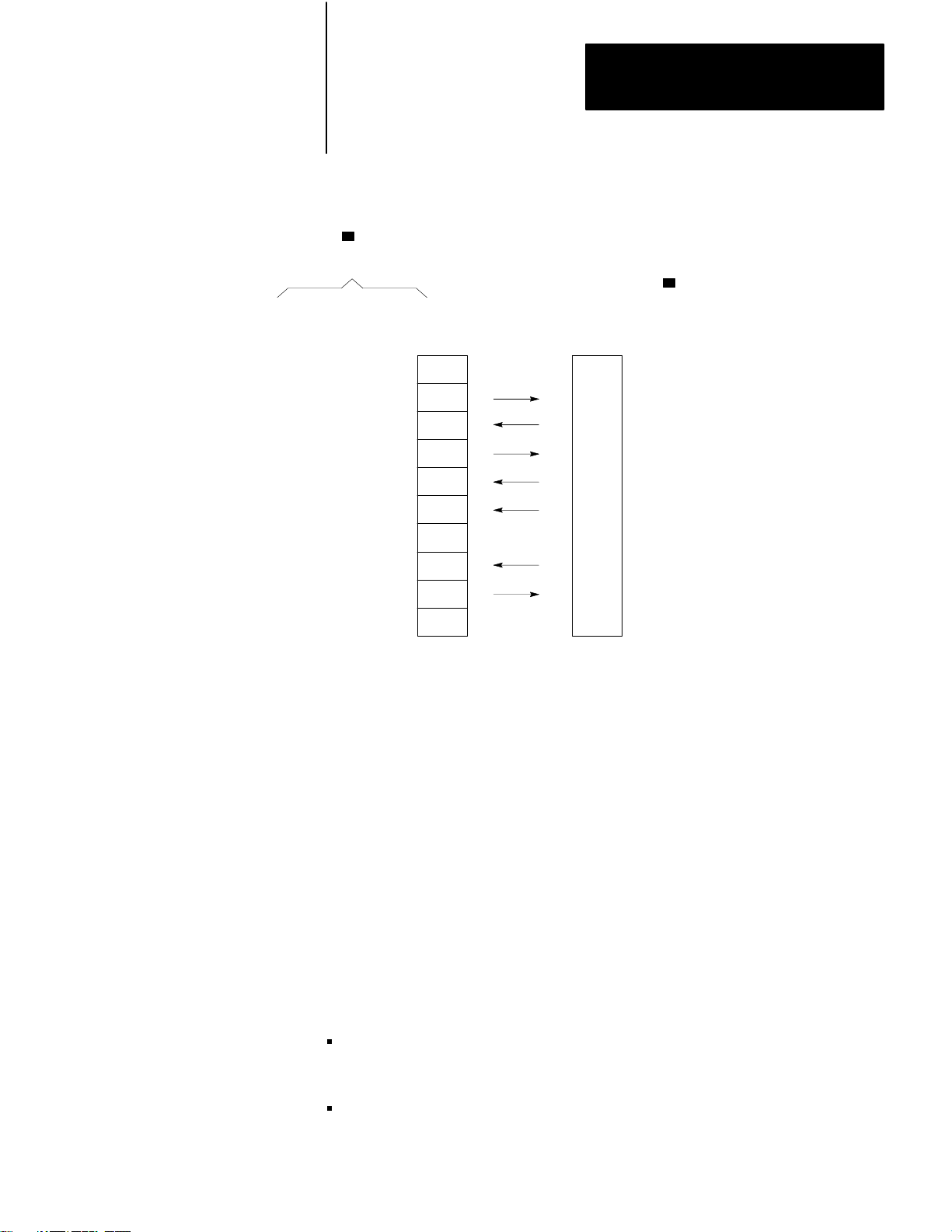
Data transfers can be either solicited or unsolicited, depending on whether
they are initiated by the local or a remote station, respectively. Either type
of station initiates the data transfer by issuing a command message. If the
local station issues the command message, the corresponding reply
message is said to be solicited because the local station has solicited, or
requested, the data contained in the reply message. If a remote station
issues the command message, that message is said to be unsolicited.
Levels of Programming
For solicited messages, a local station receives data from a remote station
during a read operation. The local station sends data to a remote station
during a write operation.
For unsolicited messages, a local station receives data from a remote
station during a write operation. A local station sends data to a remote
station during a read operation.
In read operations, the command message requests the data transfer, but
the corresponding reply message actually contains the data being
transferred. In write operations, the command message contains the data
being transferred, and the reply message merely reports the status (receipt
or non–receipt) of the transfer.
The PLC–3 processor must be free to control its own processes at the
same time that the 1775–KA module is communicating over the Data
Highway. For this reason, both the processor and the module have their
own programs and programming languages. Figure 3.1 illustrates how
these two programming levels (processor and module) interrelate.
34
PLC-3 Program
The first link in the communication process is your PLC–3 ladder diagram
program. You send a Data Highway command message by means of the
message (MSG) instruction. Figure 3.1 shows a typical MSG instruction.
Page 50

Chapter 3
Data Highway Communication
When the rung becomes true, the message instruction begins sending
command(s) across the Data Highway. At the same time, bits in a control
file word change their state (Table 3.B) to reflect the status of the
command. Even if the rung becomes false, the message command will
continue to send commands across the highway.
Table 3.B
Status of Bits in a Control File W
The
WHEN:
the message instruction is true
the enable bit (16) is set
the latched enable bit (12) is set
the remote Data Highway module has received the message instruction
the request bit (17) is set
the 1775-KA module begins operation
the busy bit (14) is set
the operation is complete
the busy bit (14) is set
either the done bit (15) or the error bit (13) is set
the rung becomes false
the request bit (17) is reset
the busy bit (14) is reset
the enable bit (16) is reset
the latched enable bit (12) is reset
the rung becomes true a second time
either the done bit (15) or the error bit (13) is reset
ord
5. Enter an extended address for the channel. In our Figure 3.1, we
address the module status area of memory, specify the 1775–KA
module, and a thumbwheel setting of 1.
6. Enter either a command or a command procedure. In Figure 3.1, we
entered the command procedure, PROC_A.
Data Highway Message Procedure
As already stated, the 1775–KA module has its own programming
language that consists of commands (Chapter 8). A group of related
commands make up a Data Highway message procedure. These
commands and message procedures determine what messages are
transmitted over the Data Highway.
35
Page 51

Chapter 3
Data Highway Communication
Data Transfers
The whole purpose of Data Highway communication is to transfer data
from one station processor memory location to another. To accomplish
these data transfers, you can program the assignment command into the
1775–KA module.
Chapter 6 gives the details of the assignment command. For now, let’s just
look at the simple example in Figure 3.2. In this example, the assignment
command copies a word (16 bits) of data from the source to the
destination location. The source of the data is always specified on the
right of the equals sign (=), and the destination is always on the left.
Figure 3.2
Example
Assignment Command
$B45:21 = $I12:33
Source Address
Address Delimiter
Asignment Command
Destination Address
Address Delimiter
36
10015-I
Note that an assignment command does not destroy the data at the source
location; rather, it just makes a copy of the source data at the destination
location. When the assignment is executed, both source and destination
will contain the same data.
There are two ways to use a data transfer command with the 1775–KA
module:
as a single command within a PLC–3 message instruction
as one of multiple commands within a message procedure
Figure 3.3 illustrates both of these methods for the same assignment
command. Note that a message instruction in the PLC–3 ladder diagram
program controls execution of the command in either case.
Page 52
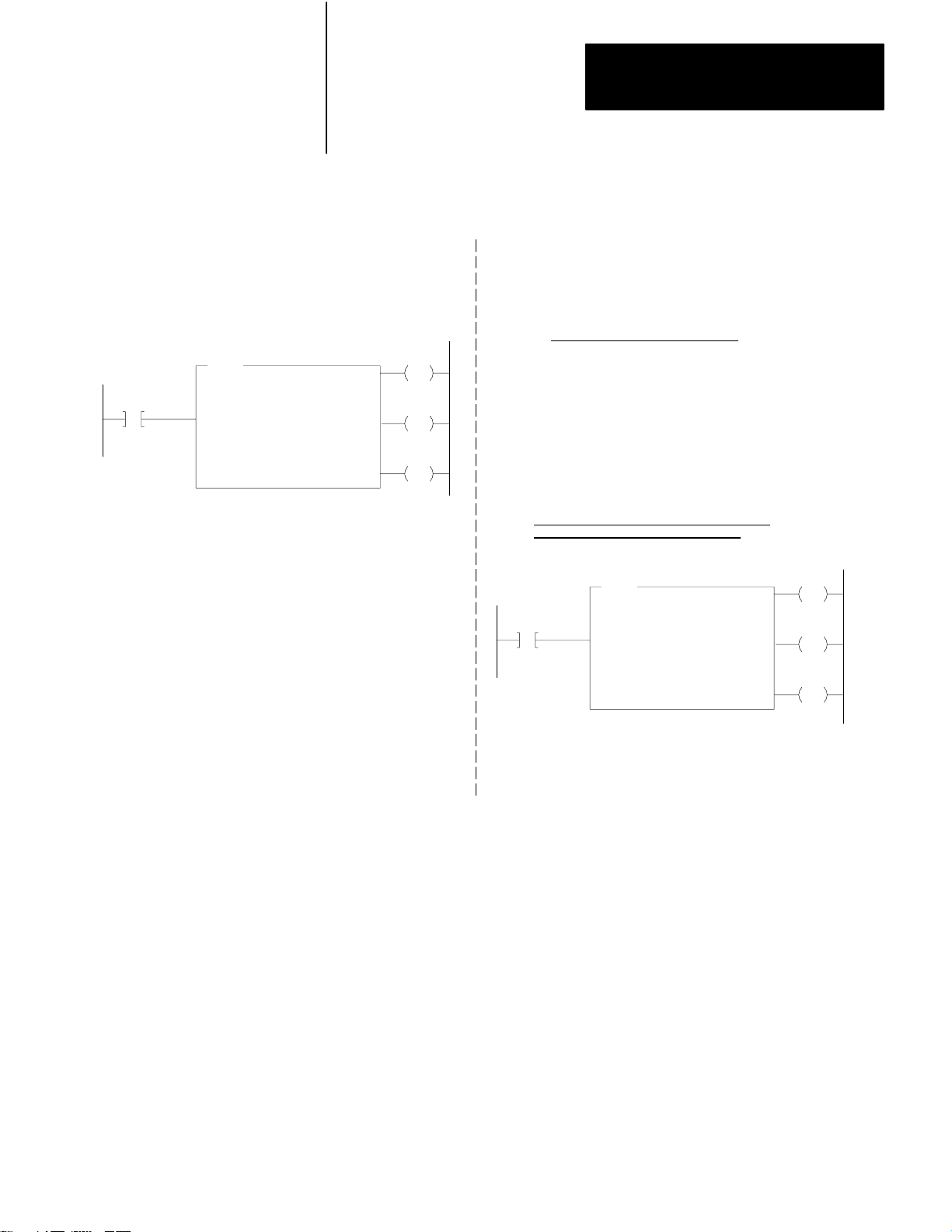
Figure 3.3
W
ays to Use 1775-KA Commands
Two
Chapter 3
Data Highway Communication
1) as a single command
in a PLC–3 message instruction
MSG
10012
01
MESSAGE TYPE 1
CTL = FB200:0000=200
CHANNEL: E2.5.1
$B45:21=$112:33
STAT
EN
12
STAT
DN
15
STAT
ER
13
2) as part of a message procedure
Message Procedure PROC_A
(other commands)
$B45:21 = $112:33
(other commands)
PLC–3 Message Instruction to Control
Execution of Procedure PROC_A
MSG
10012
01
MESSAGE TYPE 1
CTL = BW200:0000=200
CHANNEL: E2.5.01
@ PROC_A
STAT
EN
12
STAT
DN
15
STAT
ER
13
10016–I
37
Page 53

Chapter 3
Data Highway Communication
Access privileges
Not every Data Highway station can read or write to every other station.
In general, read and write access privileges depend on two factors:
type of processor at the transmitting and receiving stations
protections set at the receiving station
The rest of this section explains how these access privileges vary
according to the above factors.
PLC–3 Stations
A PLC–3 station can always read data from any major area of another
PLC–3’s memory. However, one PLC–3 station can write only to the data
table area of another PLC–3 station.
In addition, a local PLC–3 station can prevent remote PLC–3 stations
from writing to the local station’s data table by setting a memory
protection switch. At the local station, the memory protect switch can be
overridden by selecting option 4 in the Module Options Menu (section
titled Accept Writes, chapter 2) at the local station.
PLC/PLC–2 Stations
For communication with a PLC or a PLC–2 station, read, and write access
privileges depend on switch settings at that station. For an explanation of
how to set the switches for read and write access, refer to the
Communication Adapter Module User’s Manual (publications 1771–6.5.1
and 1774–6.5.8).
Accessing a PLC/PLC–2 Station
Access to a PLC/PLC–2 station also depends on the type of command
transmitted to that station. There are two types of commands:
protected write commands
unprotected read and write commands
Protected write commands can only write to specified sections of the data
table in a PLC/PLC–2 processor. Memory access rungs in the PLC/PLC–2
ladder diagram program specify where in the data table the PLC–3 can
write data.
38
Unprotected commands, on the other hand, can read or write to any
section of the data table at a PLC/PLC–2 station. (Again, refer to
publication 1771–801 or 1774–819 for an explanation of protected and
unprotected commands and memory access rungs.)
Page 54

Chapter 3
Data Highway Communication
A PLC–3 station can read from any part of a PLC/PLC–2 data table.
However, A PLC– 3 station cannot write to a PLC/PLC–2 if the switch
settings at the PLC/PLC–2 station forbid access. If the switches at the
PLC/PLC–2 station are set to accept only protected write commands, then
the ladder diagram program at the PLC/PLC–2 station must contain
memory access rungs to define which areas of the PLC/PLC–2 station’s
data table are accessible. In such a case, a transmitting PLC–3 station can
write to only those data table areas defined by the memory access rungs,
and only by means of protected write commands. If the switches at the
PLC/PLC–2 station are set to accept unprotected write commands, a
PLC–3 station can then write to any area of the PLC/PLC–2’s data table
by transmitting an unprotected write command (section titled Command
Message Type chapter 6).
Accessing a PLC–3 from a PLC/PLC–2 Processor
While a PLC–3 processor can address any area of a PLC/PLC–2 data
table, a PLC/PLC–2 reads an input file that is a part of the PLC–3 data
table. That file is the PLC–3 input file with a number that corresponds to
the station number of the PLC/PLC–2 station. For example, the
read/write files assigned to PLC/PLC–2 stations 1 to 100 (octal) would be
as follows:
PLC/PLC-2
Number (octal)
[1]
Station address 000 is assigned to input file I008. Otherwise PLC-3 input
files with an 8 or 9 in their address are not used for read/write access by a
PLC-PLC-2 station (except I008 for station 0).
Station
000 I008
001 I001
002 I002
003 I003
004 I004
005 I005
006 I006
007 I007
010 I010
011 I011
012 I012
. .
. .
. .
077 I077
100 I100
Assigned PLC-3 Input File
for Read/W
rite Access
[1]
39
Page 55

Chapter 3
Data Highway Communication
PLC/PLC–2 station numbers are octal, while PLC–3 input files have
decimal addresses. This means that PLC–3 input files with an 8 or 9 in
their address are not used for read/write access by a PLC/PLC–2 station.
The PLC/PLC–2 station can use either protected or unprotected
commands to access its assigned PLC–3 file. Note, however, that the
PLC/PLC–2 station cannot access its assigned file until that file is created
and allocated at the PLC–3. To create a PLC–3 file, use the CREATE
command described in the PLC–3 Programming Manual (publication
1775–801).
Note that it is possible to have two PLC–3 stations communicate with
each other as if they were PLC/PLC–2 stations. To do this, simply allocate
the appropriate PLC/PLC–2 buffer files in the PLC–3 stations and uses
the PLC/PLC–2 addressing format (section titled PLC/PLC–2 Address
Specifications, chapter 4) in the assignment commands. Similarly, a
computer can sent PLC/PLC–2 commands to a PLC–3 station by using
the appropriate message packet formats (Appendix A).
To allow as many as 4 remote stations to access the same PLC–3 input
file:
1. Enable the PLC–2 MASK option in the LIST function. PLC–2
MASK is option 6 on the Module Options menu.
2. Select station numbers 100
apart. For example, you could use
8
stations 010, 110, 210 and 310.
The stations will have access to the input file which matches the lower
two digits of these station numbers (input file 10 in this example). When
the 1775– KA module receives a PLC–2 type command, it masks the
upper octal digit in order to determine which input file to access. So
commands sent from stations 010, 110, 210, and 310 would all access
input file 10.
310
Page 56

Chapter 3
Data Highway Communication
PLC–4 Stations
To read or write to a PLC–4 station, you can send either protected or
unprotected commands.
Switches 2 and 3 (on the second row of switches) at the 1773–KA module
specify whether the PLC–4 station will accept unprotected and protected
commands (respectively) through the Data Highway port of the 1773–KA
module.
Switches 1 and 3 (on the third row of switches) at the 1773–Ka module
specify whether the PLC–4 station will accept protected and unprotected
commands (respectively) through the RS–232–C port of the 1773–KA
module. In all cases, if the switch is set to the closed position, the module
will accept that type of command.
311
Page 57

Chapter
4
Addressing Rules and Examples
General
This chapter presents some general rules for specifying data addresses in
message procedures. This chapter assumes that you are already familiar
with the forms and meanings of addresses in the PLC–3 and other
Allen–Bradley programmable controllers. For details on these subjects,
refer to the appropriate documentation listed in Table 4.A.
Table 4.A
Memory
Organization Documentation
Controller Document Publication
Number
(Old/New No.)
PLC-3
PLC
PLC-2
PLC-2/30
PLC-2/20
PLC-2/15
PLC-4
PLC-3 Programming Manual
PLC Programming & Operations Manuals
PLC-2 Memory Organization and Structure
PLC-2/30 Memory Organization
Memory Organization of PLC-2.20 Controller
PLC-2/15 Memory Organization
PLC-4 Microtrol Product Guide
1775-801/1775-6.4.1
1774-800/1774-6.8.1
1772-907/---------
1772-914/1772-4.4
1772-909/1772-4.3
1772-912/---------
1773-800/1773-6.5.1
In this chapter,the addressing formats are presented in shorthand notation.
The notation used is as follows:
<bit>
-
the number of a particular bit within the
addressed word
<fileaddr>
<filesym>
<offset>
-
the logical address of a PLC–3 file
-
a symbolic address of a PLC–3 file
-
the number of words between the
beginning of the file and the desired word
(offset is zero for the first word of a file)
<size>
<wordaddr>
<wordsym>
-
number of words of data to be transferred
-
the logical address of a PLC–3 word
-
a symbolic address of a PLC–3 word
41
Page 58

Chapter 4
Addressing Rules and Examples
An expression can be used in place of any of the above fields in an
address.
Number Systems
Within the above listed fields of an address specification, numbers are
interpreted as decimal (base 10) unless you indicate that they are octal
(base 8). You can specify an octal number by enclosing the number in
parentheses and starting it with a leading zero. For example, 17 is
interpreted as decimal 17, but (017) is interpreted as octal 17, or decimal
15.
An exception to the above rule occurs when addressing a word in the
input or output sections of PLC–3 memory. In these cases, the word
address <wordaddr> is normally interpreted as an octal number,
regardless of leading zeros. To express an input or output word address as
a decimal value, enclose the word address within parentheses and
eliminate leading zeros.
In addressing individual bits, parentheses have no affect on the address
interpretation The bit address <bit> is interpreted as an octal number if it
starts with a leading zero and as a decimal number if it does not start with
a zero.
Figure 4.1 illustrates these addressing conventions.
42
Figure 4.1
Examples
Address
Specification
I12:15
I12:15/15
I12:015/015
I12:(15)
I12:(015)
N43:15
N043:15
N(043):15
N(43):15 Integer file 43, word 13
of Addressing Conventions
Interpretation (expressed in decimal)
Input file 12, word 13
Input file 12, word 13, bit 15
Input file 12, word 13, bit 13
Input file 12, word 15
Input file 12, word 13
Integer file 43, word 13
Integer file 43, word 13
Integer file 35, word 13
10017-I
Page 59

Chapter 4
Addressing Rules and Examples
Addresses
Data is referenced by its address in memory. In a message procedure, you
must precede an address with a dollar sign. The dollar sign acts as a
delimiter to tell the 1775–KA module that it has encountered a data
address. Figure 4.2 illustrates this addressing format in a simple
assignment command.
Figure 4.2
Example
Assignment Command Showing Addressing Format
$B45:21 = $I12:33
<
Destination Source
Address Address
Assignment Command
For data locations at remote stations, the remote station number must
precede the data address. Figure 4.3 illustrates this addressing format.
For communication on the Data Highway, the characters #H are required
to delimit the remote station number. For RS–232–C communication
through the 1775–KA module’s modem port, the characters #M delimit
the remote station number.
<
10018-I
Figure 4.3
Example
#H024
<
of Remote Station Addressing in an Assignment Command
$B45:21 = $I12:33
<
<
Source Address
Address Delimiter
Assignment Command
Destination Address
Address Delimiter
Remote Station Number (octal)
Data Highway Port Identifier
Remote Station Delimiter
10019-I
43
Page 60

Chapter 4
Addressing Rules and Examples
Symbols
You can also use symbols to represent data and data addresses in message
procedures. A symbol can consist of numeric digits, alphabetic
characters, and the underline character (_). No other special characters
are allowed. The first character in a symbol must be a letter of the
alphabet.
Both upper–case and lower–case letters are acceptable in a symbol, but
they are distinguished. For example, ASYMBOL and Asymbol are two
different symbols.
A symbol can be any length, but it must be unique in its first 8 characters.
For example, SYMBOL_A and SYMBOL_B are distinguishable in a
message procedure, but NEW_SYMBOL_A AND NEW_SYMBOL_B
are not. Note that indistinguishable symbols are not flagged as
programming errors. Rather, indistinguishable symbols are treated as
equivalents.
Certain words and character combinations cannot be used as symbols
because they are reserved for special uses in message procedures. The
reserved words are:
CREATE IF
DELETE ON_ERROR
ERROR PROT
EXIT STOP
GOTO UNPRO
Any abbreviated form of one of the above words is also invalid as a
symbol. For example, the single letter C should not be used as a symbol
because it is an abbreviation of the word CREATE. Similarly, PRO is an
invalid symbol.
Figure 4.4 illustrates the classification of different types of symbols. The
two major classifications are:
system symbols
user symbols
44
Page 61

Figure 4.4
T
Symbol
Chapter 4
Addressing Rules and Examples
ypes
User Symbol
Generate
value
assignment command
Interprocedural
Applies to the procedure
in which it is generated
plus any other procedure
nested together with that
procedure
this symbolic
through the
Symbol
Procedural
Applies only to the
procedure in which it is
generated.
Procedure Name
Applies to a single
procedure or other
procedures nested
together
procedure.
Global
Applies to any context.
within that
System Symbol
Generate this symbol
with the Edit command
(for a procedure name)
or a Create command
(for a symbolic address).
Symbolic Address
Can
be used
in place of a logical
address.
Local
Applies only to the
context in which the
symbol
is generated.
anywhere
10021–I
System Symbols
A system symbol is used as either a procedure name or a symbolic
address. The characters in a system symbol must conform to the general
rules given above for all symbols. System symbols are delimited by the
character @, which distinguishes them from user symbols.
Procedure Names
A procedure name is a way of referring to a message procedure. You
assign a procedure name at the time you generate, or edit, the message
procedure (Chapter 6).
One procedure can execute a second procedure simply by stating the
name of that second procedure. This allows for nesting of procedures up
to three levels deep.
Symbolic Addresses
45
Page 62

Chapter 4
Addressing Rules and Examples
A symbolic address is another way of representing the logical address of
data (section titled Addresses). You can generate a symbolic address by
using the CREATE command (Chapter 8). A symbolic address can be
used anywhere that a logical address can be used in a message procedure.
The symbolic address is stored in the system symbols area of the PLC–3
memory.
Scope of System Symbols
System symbols can be either local or global in scope. A global system
symbol is known in any context. A local system symbol is known only in
the context in operation at the time the symbol was generated. Context is
explained in the PLC–3 Programming Manual (publication 1775–801).
At the time you generate the system symbol, you can specify whether it is
to be local or global. If you do not specify the scope of the system
symbol, it is assumed to be local.
Note that the terms local and global symbols should not be confused with
local and remote stations. Both local and global symbols having meaning
only at the station in which they were generated.
User Symbols
A user symbol represents a numeric value. You can generate a user
symbol and assign a value to it by means of the assignment command
(Chapter 7).
User symbols are either procedural or interprocedural. Procedural user
symbols are known only to the procedure in which they are generated.
Interprocedural user symbols are known to the procedure in which they
are generated and to any other procedure nested within that procedure.
User symbols can contain data that is up to 32 bits long. If the high–order
bits are insignificant (that is, if they can be truncated without changing the
value of the data), then the contents of the user symbol can be stored in a
data field that is less than 32 bits long. Attempting to put a data value into
a field that is too small for it will generate an error code of 189 (Appendix
B).
46
Page 63

Chapter 4
Addressing Rules and Examples
PLC-3 Address Specifications
The PLC–3 processor uses logical addresses to reference data in memory.
No PLC–3 address is valid unless it memory location has been allocated.
You can allocate memory by using the CREATE command in PLC–3
programming. The PLC–3 Programming Manual (publication 1775–6.4.1)
explains how to do this. Note that the CREATE command for memory
allocation is different than the CREATE command for creating symbolic
addresses (Chapter 6).
The following rules apply when specifying a PLC–3 logical address in a
message procedure:
1. Symbolic addresses must be defined to either the word level or the
file level of specification.
2. A word address may be either: (a) a block address specified to the
word level, (b) a symbolic address of a word, or (c) a symbolic file
address followed by a colon (:) and an offset.
3. A size specification must be preceded by a word address and a
comma (,).
4. An offset specification must be preceded by a file address and a
colon (:).
5. A bit number must be preceded by a word address and a slash (/).
6. To access the pointer or floating point sections of memory, extended
addressing must be used.
These rules are applied in the formats given below for addressing PLC–3
data locations.
Addressing a File
The format for addressing a PLC–3 file is one of the following:
<fileaddr>
<flesym>
For assignment commands that copy data from one file to another, both
the source and the destination file must be exactly the same size.
47
Page 64

Chapter 4
Addressing Rules and Examples
For PLC–3 timer and counter files, it is important to note that the data
words are stored in the following order:
CTL PRE ACC
That is, the control, preset, and accumulated values for a given timer or
counter are stored as consecutive words in the same file.
Addressing a Word Range
To address a range of words in PLC–3 memory, use one of the following
formats:
<wordaddr><size>
<filesym>:<offset>,<size>
<wordsym>,<size>
Figure 4.5 is an example of addressing a range of PLC–3 words.
Figure 4.5
Example
of Addressing a Range of PLC-3 W
ords
$N 15 : 0, 20
<
Address of first word
to be transferred.
Delimiter
You may use a word range only as the source field in an assignment
command. The destination must be a file that is as large as, or larger than,
the source range.
<
Number of words to
be transferred
10022-I
48
Addressing a Word
To address a single word in PLC–3 memory, use one of the following
formats:
Page 65

Chapter 4
Addressing Rules and Examples
<wordaddr>
<filesym>:<offset>
<wordsym>
Note that <wordaddr>is interpreted as an octal value if the addressed
word is in an input or output file. Otherwise, <wordaddr>is interpreted as
a decimal value (section titled Number Systems).
To access words in the pointer of floating point sections of PLC–3
memory, use the PLC–3 extended addressing format. You can read about
extended addressing in:
PLC–3 Programmable Controller Programming Manual (pub. no.
1775–6.4.1)
Addressing a Bit
To address a specific bit within a PLC–3 word, use one of the following
formats:
<wordaddr>/<bit>
<filesym>:<offset>/<bit>
<wordsym>/<bit>
Figure 4.6 gives some examples of addressing individual bits in PLC–3
memory.
49
Page 66

Chapter 4
Addressing Rules and Examples
Figure 4.6
Example
of Addressing Specific Bits in PLC-3 Memory
@FILE_A:16/8
<
$B1:5/012
<
Bit number 8 (decimal)
Delimiter
Word offset from bewginning of file
Delimiter
Symbolic address of file
Bit number 8 (decimal)
Delimiter
PLC/PLC-2 Address Specifications
Logical word address
10023-I
The PLC and PLC–2 processors use logical data addresses. These
addresses are usually specified as octal numbers. However, the 1775–KA
module interprets these addresses as decimal numbers unless they contain
leading zeros (section titled Number Systems). Therefore, if you want to
specify a PLC or PLC–2 word address as an octal number, begin the
number with a 0(zero).
Addressing a Word Range
To address a range of words in PLC or PLC–2 memory, use this format:
<offset>,<size>
Figure 4.7 illustrates this addressing format
You may use a word range only as the source field in an assignment
command.
410
Page 67

Chapter 4
Addressing Rules and Examples
Figure 4.7
Example
of Addressing a Range of PLC/PLC-2 W
ords
#H024$015,4
<
<
Addressing a Word
To address a single word in PLC or PLC–2 memory, use this format:
<
Number of words to be transferred (decimal)
Delimiter
Word offset from beginning of memory (octal)
Address delimiter
Remote station number
Remote data highway station delimiter
10024–I
<offset>
Addressing a Bit
To address an individual bit in PLC or PLC–2 memory, use this format:
<offset>/<bit>
Figure 4.8 illustrates this addressing format.
411
Page 68

Chapter 4
Addressing Rules and Examples
Remote Station Address Specifications
Figure 4.8
Example
of Addressing Specific Bits in PLC/PLC-2 Memory
#H015$0121/010
<
<
To specify the address of data at a remote station, use the format shown in
Figure 4.9. This format applies to both PLC–3 and non–PLC–3 remote
stations. The characters #H delimit a remote Date Highway station, and
the characters #M delimit a remote modem station.
<
<
Bit number 10 (octal)
Delimiter
Word offset from beginning of memory (octal)
Address delimiter
Remote station number
Remote data highway station delimiter
10025–I
Figure 4.9
Example
of Addressing a W
ord in a Remote PLC-3 Station
#H 020 $ B 15:9
<
<
Word address at remote station
Address delimiter
Remote station number 20 (octal)
Port identification for data highway port
Remote station delimiter
#H 020 @ WORD_9
<
Remote station addresses are subject to the following restrictions:
<
Symbolic word address defined at remote station
Remote station number 20 (octal)
Port identifier for data highway port
Remote station delimiter
10026-I
412
Page 69

Chapter 4
Addressing Rules and Examples
1. A remote address can be used only with the single equals sign (=)
type of assignment command.
2. In the assignment command, either the source or the destination, but
not both, may be a remote address.
3. A remote address may contain an embedded expression, but a remote
address may not be embedded in an expression.
Expression
Expressions use operators to combine two or more numeric values into a
single value. Table 4.B lists the operators that can be used in an
expression. These operators are listed from highest priority (1) to lowest
priority (10). Expressions may be nested within other expressions by
enclosing the inner expression within parentheses.
Table 4.B
Expression
Operators
Operator Operation
/
.NOT.
or .BNOT
*
%
+
-
.
Bit operator
Logical complement
Bitwise 32-bit complement
Multiplication of 32 bits
Division of 32 bits
Addition of 32 bits
Subtraction of 32 bits
Order of
Execution
1
1
1
2
2
3
3
<<
>>
& or .BAND.
or .BXOR. Bitwise 32-bit EXCLUSIVE OR
or .BOR.
.EQ.
.GT.
.GE.
Left arithmetic shift
Right arithmetic shift
Bitwise 32-bit AND
Bitwise 32-bit OR
Compare equals
Compare greater than
Compare greater or equal
4
4
5
6
7
8
8
8
413
Page 70

Chapter 4
Addressing Rules and Examples
Operator
Order of
ExecutionOperation
.LT.
.LE.
.NE.
.AND.
.OR.
Compare less than
Compare less or equal
Compare not equal
Logical AND
Logical OR
8
8
8
9
10
The result of an expression depends on the order in which the operators
are executed. The order of execution depends on the type of operator and
on left– to–right placement within the expression. Table 4.B gives the
order of execution for the different operators. For example, the command
$B67:45 = 6+3*2
would store the value 12 in word 45 of binary file 67. This is because
multiplication is performed before addition.
If an expression contains several operators with the same order of
execution, those operators will be executed in the left–to–right order in
which they appear within the expression. Extra set of parentheses can be
nested within each other to change the order of execution. In such cases,
the expression within the inner–most set of parentheses is evaluated first.
For example, the command
414
$B67:45=36%((6+3)*2)
would store the value 2 in word 45 of binary file 67 (% is the operator for
division).
Expressions can be used anywhere that direct numeric values can be used
within a message procedure, including within an address field. For
example, in the statement
$B67:(WORD+3)=5
the expression (WORD+3) specifies the address of a word within binary
file 67. Note that the parentheses are necessary to indicate that +3 is part
of the word address in this case.
Page 71

Chapter 4
Addressing Rules and Examples
Number Systems
Within an expression, direct values are always interpreted as decimal
(base 10) numbers unless you indicate that they are octal (base 8). You
can specify an octal value by starting the number with a leading zero. For
example, 17 in an expression is interpreted as decimal 17, but 017 is
interpreted as octal 17 (or decimal 15).
Operators
This section describes the operators listed in Table 4.B.
Bit Operator
The bit operator allows you to address a specific bit of a value stored
under a user symbol. For example, the statement
$I12:24/7=US_3/4
puts the value (0 or 1) of bit number 4 of user symbol US_3 into input file
12, word 24, bit 7.
The bit address itself can also be a user symbol or an expression. For
example, in the statement
$I12:24/7=US_3/(4+US_1)
the expression (4+US_1) specifies a particular bit within user symbol
US_3.
Note that the value appearing after the bit operator must be within the
range of values allowed for bit addresses. Since user symbols are 32–bit
values, a bit address for a user symbol must be in the range of 0 to 31
(decimal). Bit addresses for data table words must fall in the range of 0 to
15 (decimal).
Logical Operators
The logical operations are complement, AND, and OR. These operations
are used to construct logically true or false conditions. They are generally
used in decision statements such as the IF command (see section titled IF
Command, chapter 6).
415
Page 72

Chapter 4
Addressing Rules and Examples
The result of a logical complement is 1 (true) if the expression following
the .NOT. is a value of 0 (zero). Otherwise, the result is 0 (false). For
example, consider the command
$I12:24=.NOT.SYMBOL_A
If the value of SYMBOL_A is 0 (zero), then a 1 is stored in word 24 of
input file 12. If the value of SYMBOL_A IS anything other than 0, then a
0 (zero) is stored in word 24 of input file 12.
The result of a logical AND is 1 (true) if the expression preceding the
.AND. and the expression following the .AND. are both non–zero.
Otherwise, the result is 0 (false).
The result of a logical OR is 1 (true) if either the expression preceding the
.OR., the expression following the .OR., or both expressions are
non–zero. Otherwise, the result is 0 (false).
Bitwise 32–Bit Operators
Bitwise 32–bit operators manipulate the individual bits in a 32–bit
operand.
The bitwise 32–bit complement (.BNOT.) inverts the state of each bit in
the 32– bit expression. That is, bits set to 1 are inverted to 0, and bits set
to 0 are inverted to 1.
The bitwise 32–bit AND (.BAND.) forms a bit–by–bit logical AND of
two 32–bit operands. There is no carry from one bit position to the next
within the operand. For example, if
A contains the bit pattern
10101010010011110010101010101011
416
B contains the bit pattern
01110101011100100010101110001010
then the assignment C=A.BAND.B yields
C contains the bit pattern
00100000010000100010101010001010
Page 73

Chapter 4
Addressing Rules and Examples
The bitwise 32–bit EXCLUSIVE OR (.BXOR.) forms a bit–by–bit logical
EXCLUSIVE OR of two 32–bit operands. There is not carry from one bit
position to the next within the operand.
The bitwise 32–bit OR (.BOR.) forms the bit–by–bit logical OR of two
32–bit operands. There is not carry from one bit position to the next
within the operand.
Arithmetic Operators
The arithmetic operations are addition, subtracting, multiplication, and
division. These are binary (not BCD) operations that produce 32–bit
signed integer results.
A result from these arithmetic operations should normally be assigned to a
32– bit destination. The result can be assigned to a 16–bit destination only
if the result is small enough in absolute value (less than 65,535) to fit into
16 bits. If the result is assigned to a 16–bit destination but is too large to
fit into 16 bits, then an error code of 215 results.
There is no indication of overflow or underflow conditions with
arithmetic operations.
Shift Operators
When a left arithmetic shift (<<) is executed, zeros are shifted into the
rightmost bits of the expression. The leftmost bit are shifted out of the
expression and are lost.
When a right arithmetic shift (>>) is executed, the leftmost bit of the
expression does not change. If the leftmost bits is a 1, then 1’s are shifted
in from the left. If the leftmost bit is a 0 (zero), then 0’s are shifted in
from the left. Since the leftmost bit of an expression is the sign bit, this
means that the right arithmetic shift does not change the sign of a numeric
value. The rightmost bits are shifted out of the expression and are lost.
Comparison Operators
Comparison operators result in a value of 1 if the comparison is true and 0
(zero) if the comparison is false. For example, consider the command
$I12:23 = ($CACC:1.GE.$CACC:2)
417
Page 74

Chapter 4
Addressing Rules and Examples
If the accumulated value of counter 1 is greater than or equal to the
accumulated value of counter 2, then the number 1 is stored in word 23 of
input file 12. If the accumulated value of counter is less than the
accumulated value of counter 2, a value of 0 (zero) is stored in word 23 of
input file 12.
Resulting Values
The result of an expression is a 32–bit value. If the high–order bits are
not significant (that is, if they can be truncated without changing the value
of the expression), then the result can be stored in a data field that is less
than 32 bits long. Attempting to put a value into a field that is too small
for it results in an error code of 215 (Appendix B).
418
Page 75

Editing
Chapter
5
General
This chapter explains how to create and edit message procedures and
commands for the 1775–KA module. The message procedure commands
themselves are described in Chapter 6.
The general steps for editing a 1775–KA message procedure are:
1. Create and edit the PLC–3 ladder diagram program containing
message instructions to control execution of the 1775–KA message
procedure.
2. Allocate memory to the necessary PLC–3 data files.
3. Create and edit the 1775–KA message procedure.
You can perform the first two steps through an Industrial Terminal (cat.
no. 1770–T4) connected to the I/O Scanner–Programmer Interface
Module (cat. no. 1775–S4A). The third step can be performed either
through an Industrial Terminal or through a data terminal connected to the
I/O Scanner–Message Handling Module (cat. no. 1775–S4B). These steps
are described below.
Editing the Message Instruction
Table 5.A gives an example of how to edit the message instruction in the
PLC–3 ladder diagram program. For more details on this type of editing,
refer to the PLC–3 Programming Manual (publication 1775–801).
51
Page 76

Chapter 5
Editing
System Prompt
ENTER FILE ADDRESS
ENTER SYSTEM
ADDRESS OR
SYMBOL
ENTER MESSAGE
TYPE
Table 5.A
Example
of Message instruction Editing
Action
Start edits.
Insert rung.
Enter the energize bit for the message
rung. In this case, binary file 0, word 0, bit
0.
Enter the message instruction.
Enter the address of the file where the
message instruction will reside in memory
In this case, binary file 1.
Enter the channel designation for the
1775-KA module. In this case, 2 is the
module status, 5 is the 1775-KA module
type, and 1 is the thumbwheel number of
the module.
Enter the message type. This is always 1
for the 1775-KA module.
Key Strokes
SED [ENT]
IR [ENT]
-] [- B0:0/0 [ENT]
MSG [ENT]
FB1 [ENT]
.
E2.5.1 [ENT]
1 [ENT]
Allocating Memory
Editing Message Procedures
Enter a single 1775-KA assignment
command or the name of a message
procedure. In this case, the name of the
message procedure is PROC_1.
End edits.
@PROC-1 [ENT]
EE [ENT]
Before the 1775–KA module can transfer data to or from any file in
PLC–3 memory, that file must exist and it must have enough memory
allocated to it to accommodate the data transfer. You can create and
allocate a file using the PLC–3 memory management commands. Refer to
the PLC–3 Programming Manual (publication 1775–801) for a description
of memory management.
Table 5.B shows an example of editing a message procedure through an
Industrial Terminal connected to a 1775–S4A module. Table 5.C shows
how to edit the same message procedure through a data terminal
connected to a 1775–S4B module.
52
Page 77

Chapter 5
Table 5.B
Example
System Prompt
ENTER SYMBOL
STRING
ENTER SYSTEM
ADDRESS OR
SYMBOL
ENTER SYMBOL TYPE Enter the symbol type for the message
of Editing a Message Procedure Through an Industrial T
Action
Create the message procedure. In this
case, MH1 mean Data Highway message
procedure number 1.
Deleting existing null characters.
Enter message procedure commands.
Note that you must use either an EXIT or a
ST
OP command to end each procedure.
Insert the symbol definition for the name of
the message procedure.
Enter the name of the message procedure.
In this case, the name is PROC_1.
Enter the address where the message
procedure is stored. In this case, the
symbolic address MH1 can be used.
procedure name. This is always 2 for the
1775-KA module.
erminal
Key Strokes
ME, MH1, [ENT]
[DEL] [DEL] [DEL] [DEL]
(other commands)
#H022$B0:5CC:1 [ENT]
$B0:6=CC:1*2 [ENT]
EXIT [ENT]
[CANCEL CMD]
IS [ENT]
PROC_1 [ENT]
MH1 [ENT]
2 [ENT]
S4B>
<EOB>*
*
S4B>
Table 5.C
Example of Editing a Message Procedure Through a Data T
Enter the edit mode and create the
message procedure name. Note that the
1775-S4B module automatically creates
the symbol definition for the message
procedure name.
Enter the insert mode of editing
Enter the message procedure command.
Note that you must use either EXIT or
ST
OP command to end each procedure.
Exit from the insert mode of editing.
Exit from the editing mode of the
1775-S4B module.
EDIT /H@PROC_1 [RET]
I [RET]
(other commands)
#H022$B0:5=CC:1 [RET]
$B0:6=CC:1*2 [RET]
EXIT [RET]
[RET]
E [RET]
erminal
53
Page 78

Chapter 5
Editing
Note that it is not always necessary to create a message procedure. If you
want to execute just a single assignment command that is no more than 76
characters long, then you can enter that command as part of the ladder
diagram message instruction (Table 5.A). If you want to execute more
than one 1775–KA command, or if a single assignment command is more
than 76 characters long, then you must create a message procedure to
contain those commands.
Also note that every message procedure must end with either an EXIT or
a STOP command. The EXIT command is normally preferred because the
STOP command is a more extreme measure that results in error 179
(Appendix B).
54
Page 79

Chapter
Message Procedure Commands
6
General
The 1775–KA module has its own command language that you can use in
programming message procedures. This chapter describes the available
commands and gives some examples on how to use them. Table 6.A
summarizes the commands.
Table 6.A
Message
Procedure Commands
Command
=
(assignment)
CREATE
DELETE
(execute)
EXIT E
GOTO
IF
ON_ERROR
STOP S
Format and Explanation
<destination>3=<source>
Assign a numeric value to a user symbol or copy data from
the source to the destination
C@<system symbol><logical address>
Create a symbolic address and equate it to a logical address.
D @<system symbol>
Delete a symbolic address or an entire message procedure
from PLC-3 memory
@<system symbol>
Execute the named message procedure.
T
erminate execution of the current message procedure.
G <label>
Continue executing the current procedure from the point
specified by the label.
I <expression><embedded command>
Execute the embedded command only if the specified
expression is true.
O <embedded command>3
Execute the embedded command only if an error occurs after
this statement in the procedure.
T
erminate execution of the message (MSG) instruction in the
PLC-3 ladder diagram program.
.
Each command can be abbreviated to the letters shown in the format
column of Table 6.A. In general, it is best to abbreviate a command to the
shortest possible form. This not only makes the commands easier to
program, but it also saves memory space and reduces execution time.
61
Page 80

Chapter 6
Message Procedure Commands
Blanks may be inserted anywhere to improve the readability of a message
procedure. However, blanks should be kept to a minimum because they
use memory space and slow execution of the message procedure.
Assignment Command
The assignment command is the most fundamental yet versatile of all the
commands. Its primary purpose is to copy data from the source location to
the destination location. Table 6.B lists the various types of sources and
destinations. Any type of source in Table 6.B may be used with any type
of destination listed.
Table 6.B
Source and Destination T
Data
Source
Direct V
alue
Procedural user symbol
Interprocedural user symbol
Logical address Logical address
Local symbolic address Local symbolic address
Global symbolic address Global symbolic address
Expression
ypes
Destination
Procedural user symbol (except when
source is remote)
Interprocedural user symbol (except
when source is remote)
62
Of special interest is the case where a user symbol is the destination of the
assignment. In such a case, if the user symbol was not previously defined
in the message procedure, a new symbol is generated. If the symbol has
already been defined, using it again as a destination causes its value to be
changed to the value given it by the latest assignment command.
Note that you can not transfer data from another station and place it into a
user symbol defined at your local PLC–3.
Format
The equals sign (=) is the assignment command. As Table 6.A shows, the
destination for the assignment is on the left of the equal sign, and the
source or the numeric value is on the right. In all cases, the source value is
assigned to (or copied to) the destination location. Thus, the assignment
is from right to left on the command line. For example, the statement
$I12:024–US_5
Page 81

Chapter 6
Message Procedure Commands
copies the value of user symbol US_5 into word 24 (octal) of input file
12.
Modifiers
Several modifiers may be added to the basic assignment command. These
modifiers affect three aspects of the assignment:
Scope of assignment
Priority level of Data Highway message
Type of command message transmitted
Scope of Assignment
A double equals sign (==) can also be used for the assignment command.
The extra equals sign modifies the scope of an assignment involving a
user symbol. If the destination of the assignment is a user symbol, the
double equals sign defines the destination to be an interprocedural user
symbol. With the single equals sign, the destination becomes a procedural
user symbol.
For example, the statement
US_2==6
defines US_2 to be an interprocedural user symbol and assigns to it the
value 6.
Do not use the double equals sign (==) with anything other than a user
symbol as the destination.
Message Priority
Data Highway messages may be either one of the following priority
levels:
63
Page 82

Chapter 6
Message Procedure Commands
Normal
Priority
If you use the less–than sign (<) with the assignment command, the
command will generate a priority Data Highway message. Without the
less–than sign, the assignment command will generate a normal Data
Highway message.
For example, the statement
#H027$I15:4<=$I12:24
transmits a priority message to Data Highway station 27 (octal).
The priority modifier can be used with either type of assignment (=or==).
Important: Stations with high priority messages are given priority over
stations with normal priority messages throughout the command/reply
cycle. For this reason, a command should be given a high priority
designation only when special handling of specific data is required. Using
an excessive number of high priority commands defeats the purpose of
this feature and could delay or inhibit the transmission of normal priority
messages.
Command Message Type
Command messages are of two types:
protected
unprotected
As explained in section titled Data Transfers, (chapter 3), protected
commands can access only specified areas of data table memory at a
PLC/PLC–2 station. You will need to send a protected write command
only if a switch at the remote PLC/PLC–2 prohibits other stations from
sending unprotected write commands. Unprotected commands can access
any area of the data table.
64
By default, command messages generated by the assignment command in
PLC–3 message procedures are of the protected type. To generate an
unprotected command message, use a blank space and the modifier U
after the assignment command.
Page 83

Chapter 6
Message Procedure Commands
For example, the command
#H027$0121=17407
would generate a protected write command to write the value 1740–7 into
word 121 of Data Highway station 27. The command
#H027$0121=17407 U
would generate an unprotected command to do the same thing.
You may disable the transmission of unprotected commands through LIST
options (section titled Module Options, chapter 2).
CREATE Command
The CREATE command generates a symbolic address and assigns it to a
logical address. Table 6.A illustrates the format of the CREATE
command. To create a local symbolic address, use the CREATE command
by itself (the modifier/LOCAL is optional). To create a global symbolic
address, use the modifier/GLOBAL after the CREATE command. In
either case, the symbol has meaning only at the station where it was
created.
The modifier/GLOBAL can be abbreviated to /G, and /LOCAL can be
abbreviated to /L. For example, the statement
C/G @ TOTAL $E0.0.0.7
creates the global system symbol TOTAL to represent the logical address
E0.0.0.7.
Note that this CREATE command for generating symbolic addresses
should not be confused with the CREATE command for allocating file
space in PLC–3 programming (Chapter 4).
DELETE Command
The DELETE command serves three main purposes:
Deleting message procedures from PLC–3 memory
Deleting symbolic addresses
Deleting interprocedural user symbols
65
Page 84

Chapter 6
Message Procedure Commands
Using the DELETE command on a procedure name not only deletes the
name but also erases the named procedure from PLC–3 memory. Using
DELETE on a symbolic address or interprocedural user symbol merely
deletes the symbol, but the data stored under that symbol remains intact.
Table 6.A shows the general format of the DELETE command. To delete
a symbol or a procedure from the current context, use the DELETE
command by itself (the modifier /LOCAL is optional). To delete a
symbol or a procedure from all contexts, use the modifier/GLOBAL after
the DELETE command.
The modifier /GLOBAL can be abbreviated to /G, and /LOCAL can be
abbreviated to /L. For example, the statement
D/G @ PARTS_PGM
Execute
deletes the procedure PARTS_PGM from all contexts in PLC–3 memory.
Note that the /LOCAL modifier can be used on global system symbols. In
such cases, the procedure or the symbol is deleted from the current
context but can still be used in the other contexts.
To execute a message procedure, simply enter the delimiter @ followed
by the procedure’s name. For example, the statement
@FIRST_PROC
causes execution of the procedure named FIRST_PROC.
Procedure names may be used anywhere that command can be used. In
this way, one procedure can execute (call) another procedure. This allows
for nesting of procedures. However, procedures may not be nested more
than 3 layers deep.
EXIT Command
66
The EXIT command terminates execution of the current message
procedure. If the current procedure was called (executed) by another
procedure, the EXIT command returns control to the calling procedure.
Control returns to the line following the execute statement.
Page 85

Chapter 6
Message Procedure Commands
The format of the EXIT command is simply the single letter
E
Without any modifiers or parameters.
Each main procedure and nested procedure must end with either an EXIT
command or a STOP command. The EXIT command is the preferred
means of ending a procedure because the STOP command results in error
179 (Appendix B).
GOTO Command
The commands in a message procedure are normally executed
sequentially. The GOTO command can change the order of execution.
Table 6.A illustrates the format of the GOTO command. Note that the
parameter for a GOTO command is a label. Labels are signposts, or tags,
that mark a location within the message procedure.
To generate a label, simply enter it on any one of the lines in a message
procedure. The format for the label is
LABEL _A:
Nothing else may appear on the same line with the label. The label itself
must conform to the same rules of construction as user symbols do. The
trailing colon (:) is required when you first generate the label, but do not
use the colon any other time you refer to the label.
When a GOTO command is encountered, execution of the message
procedure resumes with the first command after the label specified in the
GOTO. Note that you cannot use the GOTO command to jump from one
procedure to another, even if the procedures are nested.
IF Command
The IF command makes logic decisions in the message procedure. Table
6.A shows the format of the IF command. The first parameter of the IF
command is an expression (Chapter 4). The entire expression must be
enclosed in a set of parentheses. The expression may be made as complex
as desired through the use of multiple operators and nested expression.
The second element in the IF command is an embedded command. If the
value of the expression is true (1), the embedded command is executed. If
67
Page 86

Chapter 6
Message Procedure Commands
the value of the expression is false (0), the embedded command is not
executed. The embedded command may be any of the available
commands except another IF or an ON_ERROR.
Figure 6.1 demonstrates the combination of a label, a GOTO command,
and an IF command to construct a simple loop that assigns the integers 0
through 7 to successive words in binary file 50.
Figure 6.1
Example
of Looping
NUM = 0
ON_ERROR Command
LOOP: $B50:(NUM) = NUM
NUM = (NUM +1)
IF (NUM .LE. 7) GOTO LOOP
10027-I
The ON_ERROR command specifies what action should be taken if an
error is encountered during execution of the message procedure. The
ON_ERROR command is not executed sequentially in the procedure; it is
executed only when an error occurs.
Table 6.A illustrates the format of the ON_ERROR command. The
ON_ERROR command contains an embedded command that is executed
when an error occurs.
The ON_ERROR command applies to all other commands between itself
and the next ON_ERROR command. For example, consider the following
sequence:
68
Page 87

Chapter 6
Message Procedure Commands
command line 1
command line 2
ON_ERROR GOTO RECOVER
command line 3
command line 4
ON_ERROR ERR_CODE = $B2:16
command line 5
In this sequence, the first ON_ERROR command applies to command
lines 3 and 4, while the second ON_ERROR command applies to
command line 5.
Some command lines might not have an ON_ERROR command that
applies to them. If an error occurs in such a command line,the procedure
will stop executing.
STOP Command
Appendix B lists the error conditions.
The STOP command terminates execution of the MSG instruction in the
PLC–3 ladder diagram program. This means that the STOP command
stops execution of the current procedure and all procedures nested
together with the current one.
The format of the STOP command is simply the single letter
S
without any modifiers or parameters.
The STOP command is a drastic means of terminating a message
procedure, so it should be used only when no other action is possible. The
normal means of terminating a procedure is the EXIT command (section
titled EXIT Command). When the STOP command is used, it results in an
error code of 179 (Appendix B).
Functions
In addition to containing commands and nested procedures, a message
procedure can also contain functions. Functions can be used anywhere
expressions can be used.
69
Page 88

Chapter 6
Message Procedure Commands
There are two functions:
TO_BCD
FROM_BCD
Figure 6.2 illustrates the format of these functions as they might appear in
an assignment command.
Figure 6.2
Examples
of TO-BCD and FROM-BCD Functions
$D:12 = TO_BCD (27)
COUNT = FROM_BCD ($D:12)
<
The parameter of the function must be enclosed in parentheses. The
parameter may be any one of the following:
A direct numeric value (either decimal or octal)
An expression
A user symbol
A logical address
A symbolic address
<
<
Function Parameter
Function
Assignment Command
Destination of
Resulting Value
10028–I
610
TO_BCD Function
The TO_BCD function converts its parameter into a binary coded decimal
value that is 32 bits long. For example, the TO_BCD function in
Figure 6.2 stores the number 27 in binary–coded–decimal format in word
12 of the decimal section of PLC–3 memory. After this function is
executed, word 12 will contain the following bit pattern:
0000 0000 0010 0111
Page 89

Chapter 6
Message Procedure Commands
FROM_BCD Function
The FROM_BCD function converts its parameter from
binary–coded–decimal format to binary format. The resulting value is 32
bits long. For example, the FROM_BCD function in Figure 6.2 converts
the contents of decimal word 12 from binary coded decimal to a regular
decimal value of 27. From the above example (section titled TO_BCD
Function), the FROM_BCD function stores the following bit pattern in
user symbol COUNT:
0000 0000 0000 0000 0000 0000 0001 1011
As you can see from these examples, TO_BCD and FROM_BCD perform
opposite functions.
Comments
You can add your own explanatory comments to any command line in a
message procedure. To do this, enter a semicolon (;) after the command.
Then enter your comment after the semicolon. Figure 6.3 illustrates the
format for comments.
Figure 6.3
for Comments
Format
COUNT = 0 ; INITIALIZE COUNTER
<
Anything that appears between a semicolon and the end of the command
line is considered to be a comment. Comments may be any length. The
end of the command line, and therefore the end of your comment, is
delimited by the carriage– return and line–feed pair of characters.
<
Comment
Comment Delimiter
Command
10029–I
A comment can be the only thing on a line. Do not use comments on the
same line as label. Doing so will cause errors in the message procedure.
611
Page 90

Error Reporting
Chapter
7
General
Reporting Error Codes
Recovery from Errors
The 1775–KA module detects and reports various types of errors.
Appendix B lists all the errors reported by the module. As you can see
from the appendix, some of the error codes relate to communications over
the Data Highway, while others relate to programming errors in the
message procedures.
The 1775–KA module reports errors by their code numbers. The module
stores the error code in the interprocedural user symbol ERROR. The
symbol ERROR should be reserved exclusively for error reporting by the
module, so do not use this symbol for any other purpose.
ERROR contains only the last error encountered during execution of a
command or message procedure. If you want to save the error code or
manipulate it in any way, use an assignment command to copy the code
into a more permanent storage word.
Unless you specify differently, the 1775–KA module will stop executing
the current message procedure as soon as the module detects an error. To
specify a different action, use the ON_ERROR command in the message
procedure. Then, when the module encounters an error, it will perform the
action specified in the nearest preceding ON_ERROR command. After
the module is done performing the ON_ERROR action, it will resume
executing the message procedure at the next command line after the one
in which the error occurred.
For example, a message procedure can contain the command
ON_ERROR @ RECOVER
When an error occurs in the procedure, the above command will cause the
1775–KA module to execute the procedure named RECOVER. The
procedure RECOVER might be a routine for monitoring error codes.
After executing RECOVER, the module will resume executing the
original procedure at the next command line following the one in which
the error occurred.
71
Page 91

Chapter 7
Error Reporting
Error Monitoring
To aid in error monitoring, the 1775–KA module maintains a 6–word
error block in the module status area of PLC–3 memory. This error block
contains the following information:
Word 0 – error code for the last error that occurred in the current
message procedure
Word 1 – total number of errors that occurred in the current message
procedure
Word 2 – always contains the value 1
Word 3 – line number where the error occurred in the highest level
(nest level 1) message procedure
Word 4 – line number where the error occurred in the next highest level
(nest level 2) message procedure
Word 5 – line number where the error occurred in the lowest level (nest
level 3) message procedure
The error codes reported are those listed in Appendix B.
The line number is the relative location of a command line from the
beginning of the message procedure containing the line. The first line of
each procedure is line number 1, and any following lines are numbered in
ascending sequence. Nested procedures begin with line 1 again, thus the
need for words 3, 4, and 5 in the error block.
You do not enter the line numbers for a procedure; the 1775–KA module
automatically keeps track of the line numbers for you. The line numbers
do not appear in a listing of the message procedure, but they are recorded
internally by the module.
Error Block Operation
Figure 7.1 illustrates how the error block works. In this figure, an
addressing error (invalid destination address) occurs in procedure SUB2,
which is nested 3 levels deep. Word 5 of the error block gives the line
number where the error occurred in procedure SUB2. Word 4 gives the
number of the line in procedure SUB1 that executed procedure SUB2.
72
Page 92

Chapter 7
Error Reporting
And word 3 gives the number of the line in procedure MAIN that
executed procedure SUB1.
Line Number
150
28
MAIN
SUB 1
Figure 7.1
Examples
of Error Block Operation
Procedure Word
•
•
•
@SUB 1
•
•
•
•
•
•
@SUB 2
•
•
•
Error Block
Contents (decimal)
0
1
2
3
124
1
1
150
28
5
SUB 2
4
•
5
•
•
5
6:12 = COUNT
•
•
•
10030–I
73
Page 93

Chapter 7
Error Reporting
Note that an ON_ERROR or an IF command may contain an embedded
command to execute another procedure. In these cases, the embedded
execute command is treated just like a nesting level. Figure 7.2 illustrates
this point for an ON_ERROR command. In this figure, an addressing
error in line 10 of procedure MAIN causes activation of the ON_ERROR
command, which calls for execution of procedure SAM. But SAM also
contains an error. The error in SAM is the last one detected, so it is the
one finally reported in the error block. Since procedure SAM is called by
the ON_ERROR command in procedure MAIN, the nesting for SAM is 2
levels deep.
Figure 7.2
Examples
Line Number Procedure Word
MAIN
1
ON_ERROR @SAM
•
of ON_ERROR Nesting
0
•
10
7.2 = 1000
•
•
1
•
2
SAM
3
•
•
8
•
•
4
•
$25:0 = N
•
•
5
Error Block
Contents (decimal)
160
2
1
1
8
0
74
10031–I
Page 94

Chapter 7
Error Reporting
Access to Error Block
The error block retains its data even after the message procedures are
done executing. It is re–initialized with each execution of a MSG
instruction in the PLC–3 ladder diagram program.
The extended address for the beginning of the error block file is
$E2.5.nn.4.0.
where “nn” is the thumbwheel number of the 1775–KA module. You can
access this error block by any one of the following means:
Displaying it through the front panel of the PLC–3 controller
Using the data monitor mode of the Industrial Terminal (cat. no.
1770–T4)
Using the move status (MVS) command in the PLC–3 ladder diagram
program
Using the I/O Scanner–Message Handling Module (cat. no. 1775–S4B)
Using the 1775–KA module
Using the 1775–GA
75
Page 95

Programming Examples
Chapter
8
General
Individual Commands
I0012
01
This chapter presents some detailed examples of 1775–KA module
commands and message procedures.
The first set of examples shows individual commands that could be
programmed directly into a PLC–3 message (MSG) instruction. Figure
8.1 illustrates the differences in reading and writing data between two
PLC–3 stations. Figure 8.2 shows how to write different types of data to a
remote PLC–3 station. Figure 8.3 shows how to write different types of
data to a remote PLC or PLC–2 station.
Figure 8.1
Reading
Reading word 5 of binary file 3 at data highway station 045 into word 17 of integer file 4.
and W
riting PLC-3 Data W
ord
MSG
MESSAGE TYPE 1
CTL = FB200:0000=200
CHANNEL: E2.5.1
$NA:17=#H045 $B3:5
STAT
EN
12
STAT
DN
15
STAT
ER
13
I0012
02
Destination
(local)
Writing word 5 of binary file 3 into word 17 of integer file 4 at data highway station 045.
MSG
MESSAGE TYPE 1
CTL = FB200:0001=200
CHANNEL: E2.5.1
#H045=N4:17 $B3:5
Destination
(remote)
Source
(remote)
Source
(local)
STAT
EN
12
STAT
DN
15
STAT
ER
13
10032-I
81
Page 96

Chapter 8
Programming Examples
Data Type Assignment Statement
File #H045$N4 = $B3
Figure 8.2
Data to a Remote PLC-3 Station
Writing
Destination file must be
exactly the same size as
source file.
Word range
Word #H045$N4:17 = $B3:5
Bit #H045$N4:17/5 = $B3:5/13
#H045$N4:17 = $B3:5,20
Destination file must be large
enough to accept full range
being transferred.
20 words starting at
word 5 of binary file 3
Decimal bit numbers
10033-I
82
Page 97

Figure 8.3
riting Data to a Remote PLC/PLC-2 Station
W
Data Type Assignment Statement
File #H021$040 = $B3
Destination PLC/PLC–2 file
must be at least as large as
source PLC–3 file.
Chapter 8
Programming Examples
Word range
Word #H021$040 = $B3:5/13
Bit #H021$040/5 = $B3:5/13
Priority Write
Unprotected Write ––
(refer to publication 1771–802 or 1774–6.5.8.)
affected by switch settings at remote PLC/PLC–2 station
#H021$040 = $B3:5,20
Destination file must be large
enough to accept all words
being transferred.
#H021$040 <= $B3:5
20 words starting at
word 5 of binary file 3
Decimal bit numbers
Priority assignment
command
#H021$040 = $B3:5 U Unprotected command
Space required
10034-I
83
Page 98

Chapter 8
Programming Examples
Message Procedure
Figure 8.4 presents a printed listing of a Data Highway message
procedure. As the listing indicates, the purpose of the procedure is to
monitor the state of a status bit in a remote Data Highway station.
Figure 8.4
Example
; PROCEDURE –– @REM_TURNON
; This procedure will monitor the state of a bit in a remote
; station and, when that bit goes true, turn on a bit
; locally for either 300 seconds or until the remote bit
; goes false.
;
ON_ERROR @LOG_ERROR
A = = 0
CREATE @TIM–START $B0:0
CREATE @TIM_CTL $TCTL:1
CREATE @TIM_PRE $TPRE:1
T_ON_BIT = 0
T_DONE_BIT = 017
CREATE @PROCESS $N3:7
P_ON_BIT = 5
ON = 1
OFF = 0
LOOP 1:
B0:0/1 = $H023$B5:3/2
IF ($B0:0/1 .EQ. OF) GOTO LOOP1
@TIM_PRE = 300
@TIM_START/T_ON_BIT = ON
@PROCESS/P_ON_BIT = ON
LOOP 2:
$B0:0/1 = $H023$B:3/2
IF (($B0:0/1 .EQ. ON) .AND. (@TIM_CTL/T_DONE_BIT .EQ. OFF)) GOTO LOOP2
@PROCESS/P_ON_BIT = OFF
EXIT
; PROCEDURE –– @LOG_ERROR
;This procedure will fetch the error block out of the
; Module Status Area and record it along with the time
; of day in status file 5.
;
CREATE @STATUS $S5
CREATE @ERR_BLK $E2.5.1.4.0
CREATE @TOD $S1:3
@STATUS: (A) = @ERR_BLK,6
@STATUS: (A + 6) = @TOD,2
IF ((ERROR .GE. 81) .AND. (ERROR .LE. 92)) GOTO NO_STN :no station – fatal error
IF (A .GE. 72) GOTO TIMEOUT
A = = A + 8
EXIT
;
NO_STN:
$S4:3/5 = 1
STOP
;
TIMEOUT:
$54:3/4 = 1
EXIT
Data Highway Message Procedure
;log errors and time of day
;initialize error pointer
;timer start word
;timer control word
;timer preset word
;timer on bit
;timer done bit
;process word
;process on bit
;check remote bit in loop
;fetch and save remote bit
;set timer for 300 sec
;turn timer on
;turn process on
;check timer and remote bit in loop
;fetch and save remote bit
;copy error block (6 words)
;copy time of day (hrs, mins)
;after ten errors, tell operator
;energize 1775–S4B report generation rung
;exit procedure with an error
;energize 1775–S4B report generation rung
;return to @PREM_TURNON
10035-I
84
Page 99

Chapter 8
Programming Examples
Some of the statements in the sample procedure are not necessary to
accomplish the bit monitoring. However, they were included to illustrate
more of the functions and programming techniques available with the
1775–KA module.
Note that the 300 second timer used in this example is not an accurate,
real– time clock. This is because the time between successive executions
of the bit/timer check depends on Data Highway activity and on the
activity of the local PLC–3 processor. For example, if the 300 second
timer times out immediately after its done bit is checked, the 1775–KA
module will not detect this condition until its next pass through LOOP2.
If the Data Highway is busy with other activity, it will take a while for
LOOP2 to check the remote bit. PLC–3 ladder diagram programming
provides better timer updates and responses.
The example procedure also assumes that the referenced memory areas
have been created. Specifically:
1. Status file S5 must be big enough to hold a reasonable number of
timeout errors (error #37).
2. Timer T1 is a one–second timebase timer. Bit B0:0/0 controls the
ladder diagram rung that activates the timer. Figure 8.4 refers to this
bit as TIM_START/T_ON–BIT.
3. Bit S4:3/4 activates a message instruction that executes a report
generation procedure. In this way, the 1775–KA module can
indirectly cause execution of a report generation procedure to display
a message on the operator’s terminal.
85
Page 100

Chapter
Computer to PC Communication
9
Introduction to Layered Communication
This chapter and the chapters that follow (10,11, and 12) described how to
write a software driver that enables your computer to communicate
through the RS–232–C port of the PLC–3 Communication Adapter
Module. Therefore, you do not need to read these chapters if you are only
using PC’s. The interface modules contain software drivers for PC to PC
communication.
In this chapter and the chapters that follow (10,11, and 12) we describe a
layered approach to writing a software driver for your computer.
According to the standard for network architecture developed by the
International Standards Organization (ISO), communication networks
should be divided into layers. Each layer performs specific functions. By
separating the communication network into independent layers, it is easier
to make changes to one of the network’s functions without having to
redesign the entire network. Ideally, the layers of a network should be as
independent of one another and interact with one another in the same way
as the organs of the human body. Because the organs of the human body
are independent of one another, it’s possible for a surgeon to operate on
the lungs or heart without losing the life of the patient. Yet at the same
time the organs of the body interact when we run or walk or type on a
word processor.
You should use a layered approach to developing communication software
for your computer. You don’t have to design your communication
software in this layered fashion, but your software must perform all the
functions described for the layers in this manual. In most cases, it will be
easier for you to implement and debug the communication software if you
follow this layered approach.
The Data Highway uses these four layers of the ISO model for
communication between stations:
application layer – provides the Data Highway commands that you use
to transfer data and manage the network.
network layer – determines how you address a Data Highway
command. It also provides less visible functions, such as controlling
the flow of information, establishing a path between stations, and
routing messages from your station to another station.
91
 Loading...