

Page 1
Auxiliary Function PROM
(Cat. No. 1772AF4)
for the Mini-PLC-2/15 Controller
User Manual
Page 2

Table of Contents
Introduction 11. . . . . . . . . . . . . . . . . . . . . . . . . . . . . . . . . . . .
General 11. . . . . . . . . . . . . . . . . . . . . . . . . . . . . . . . . . . . . . . . . . .
Functions 12
Applications 12
Manual's Purpose 12
Audience 12
Installation 21. . . . . . . . . . . . . . . . . . . . . . . . . . . . . . . . . . . . .
General 21. . . . . . . . . . . . . . . . . . . . . . . . . . . . . . . . . . . . . . . . . . .
Installation/Removal Handling Instructions 21
Installation 22
Removal 24
Programming 31. . . . . . . . . . . . . . . . . . . . . . . . . . . . . . . . . . .
General 31. . . . . . . . . . . . . . . . . . . . . . . . . . . . . . . . . . . . . . . . . . .
AF4 Function Sequence 32
AF4 Automatic Checks 33
Programming
. . . . . . . . . . . . . . . . . . . . . . . . . . . . . . . . . . . . . . . . .
. . . . . . . . . . . . . . . . . . . . . . . . . . . . . . . . . . . . . . . .
. . . . . . . . . . . . . . . . . . . . . . . . . . . . . . . . . . .
. . . . . . . . . . . . . . . . . . . . . . . . . . . . . . . . . . . . . . . . . .
. . . . . . . . . . . . . . . . . .
. . . . . . . . . . . . . . . . . . . . . . . . . . . . . . . . . . . . . . . . .
. . . . . . . . . . . . . . . . . . . . . . . . . . . . . . . . . . . . . . . . . .
. . . . . . . . . . . . . . . . . . . . . . . . . . . . . . .
. . . . . . . . . . . . . . . . . . . . . . . . . . . . . . . .
Specific Mathematical Functions
37. . . . . . . . . . . . . . .
Page 3

Introduction
Chapter
1
General
Installation of the Auxiliary Function (AF) PROM (cat. no. 1772-AF4 in your
Mini-PLC-2/15 controller lets you expand its mathematical capabilities.
For simplification, throughout this manual we refer to the Auxiliary Function
PROM (cat. no. 1772-AF4) as the AF4.
The AF4 can only be used with the series A Mini-PLC-2/15 processor module,
firmware revision 11 or later (cat. no. 1772-LV). The AF4 can only be used
with the series B Mini-PLC-2/15 processor module, firmware revision 4 or later.
Programming the AF4 functions with either series Mini-PLC-2/15 processor
module requires the Industrial Terminal (cat. no. 1770-T3).
The AF4 has a 2K (16 bit) word section to which you can transfer your program
(for backup memory) and a 2K word section for higher mathematical functions.
You can only transfer your program into the AF4 with the series B PLC-2/15
controller (Table 1.A). Series A Mini-PLC-2/16 Processor EPROM (publication
1770-91) describes program transfer to PROM. With the series A PLC-2/15
controller, program transfer to the AF4 is not possible.
Table 1.A
AF4
PROM Response Controller
MiniPLC2/15 Controller
[1]
2K section for higher mathematical functions would also be erased and all AF1 function
capabilities lost. Once erased, the AF4 functions are irretrievable.
NOTE: The AF4 is sensitive to ultraviolet (UV) light, therefore when exposed
to UV light, both the program and the auxiliary functions are erased. The AF4’s
transparent window is covered with the product label to avoid accidental
alteration of memory from ultraviolet light sources. Do not remove this label.
Series
Read Write Erase [1]
AYesNo No
BYesYes No
You can erase the 2K memory backup portion of the AF4 with ultraviolet light. However, the
User Program 2K Words
11
Page 4

Chapter 1
Introduction
Functions
Applications
The AF4 performs the following arithmetic functions:
Six digit add and subtract
Six digit multiply and divide
BCD to binary conversion
Binary to BCD conversion
Logarithm of a three digit number to the base 10
Logarithm of a three digit number to the base 3
Exponential function -e
Power function -y
+X
+X
Reciprocal of a number - 1
+X
Sine of an angle - sin X
Cosine of an angle - cos X
Square root of a number -x
0.5
These arithmetic functions have applications in various industries such as food
processing, machine tool work, and material handling. Applications in these
industries could be weighing, blending, batch processing, scaling, positioning,
test stands, and heat treating. The square root function is frequently used for
flow measurement and in mining applications.
Manual's Purpose
Audience
This manual shows you how to install and program the AF4 in your
Mini-PLC-2/15 controller.
We assume that you are familiar with programming and operation of the
Mini-PLC- 2/15 and the Industrial Terminal (cat. no. 10770-T3). If this is not
the case, refer to the appropriate publications or see our Publication Index
(publication SD499).
WARNING: : Use only Allen-Bradley authorized programming
devices to program Allen-Bradley programmable controllers.
Using unauthorized programming devices may result in
unexpected operation, possibly causing equipment damage
and/or injury to personnel.
12
Page 5

Installation
Chapter
2
General
Installation/Removal Handling Instructions
During AF4 installation, take special care not to bend or contaminate the pins.
Bent or dirty pins can prevent proper AF4 programming and use. The AF4’s
transparent window is covered with the product label to avoid accidental
alteration of memory from UV light sources. Do not remove this label. Store
the AF4 in its shipping container when not installed in a Mini-PLC-2/15
processor.
The AF4 can be damaged during routine handling if proper precautions are not
taken to reduce static electricity discharges.
Recommended precautions include:
Handle the AF4 by the case without touching its pins.
Use a static free work station.
Wear a conductive wrist strap which has a minimum 200k ohms resistance
and is connected to earth ground.
Ground tools prior to contacting the AF4.
Connect static-free work station to ground through a minimum 200k ohm
resistance.
Control the relative humidity of the installation area - ideal conditions are
40% to 60% relative humidity.
The following is a list of things that should not be done:
Do not handle styrofoam, plastic, or cellophane-covered articles such as
combs, cigarette packages, and candy immediately prior to handling an AF4.
Do not hand the AF4 to someone who is not antistatic protected.
Do not install the AF4 in areas which might contaminate or foul the pins of
the AF4 device.
Do not handle the AF4 by its pins.
Do not slide the AF4 across any surface.
Do not place the AF4 in a non-conductive plastic bag.
21
Page 6
Chapter 2
Installation
When these precautions are followed, the potential difference between the AF4
pins is reduced thereby reducing the problems associated with static discharges.
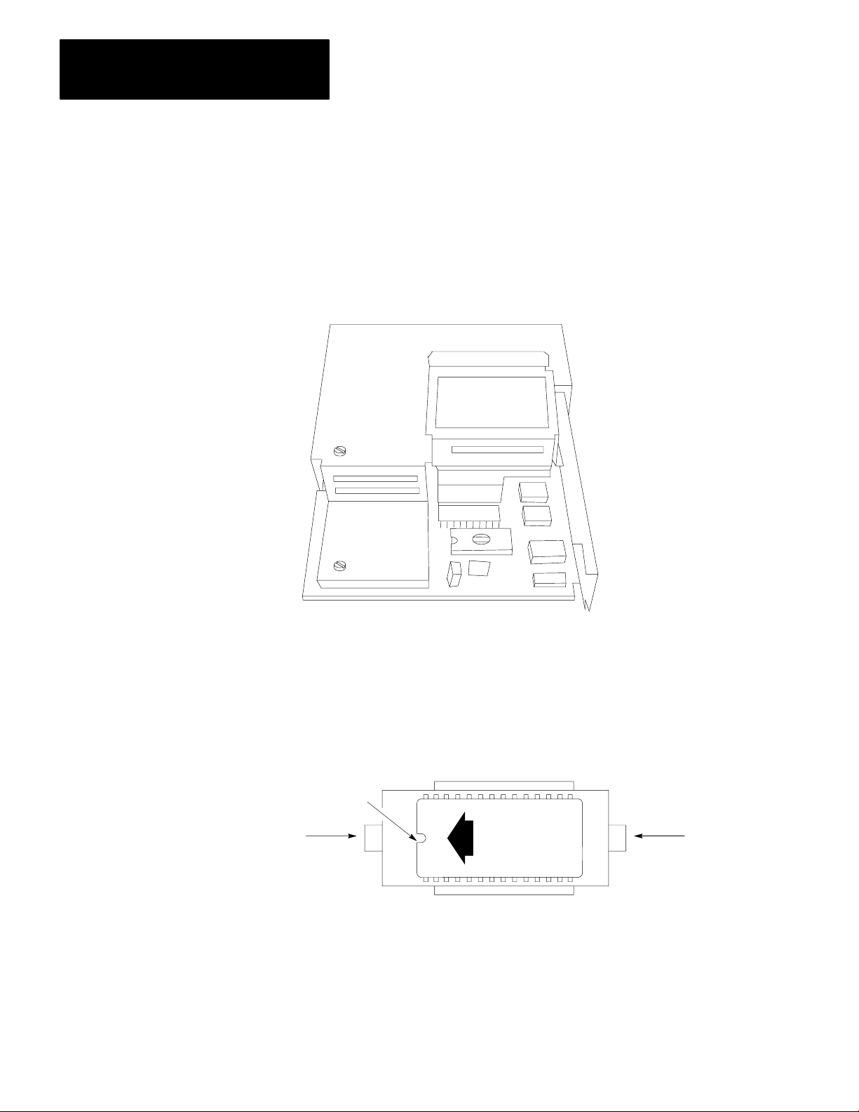
Installation
The AF4 fits into a 28-pin ZIF (zero insertion force) socket, which is located
under a hinged door at the lower side of the Mini-PLC-2/15 processor
(Figure 2.1).
Figure 2.1
PROM
Socket
10715I
On the underside of the PROM door is a label that illustrates PROM
installation. The notch on the AF4 PROM, when installed, must correspond to
the notch shown on the label. Figure 2.2 shows a properly installed AF4.
22
Figure 2.2
AF4
Installed
PROM
Notch
Lock
OFF
PROM Installation
1772AF4
DO NOT
UP
ERASE
ON
Release
11590
Page 7
Chapter 2
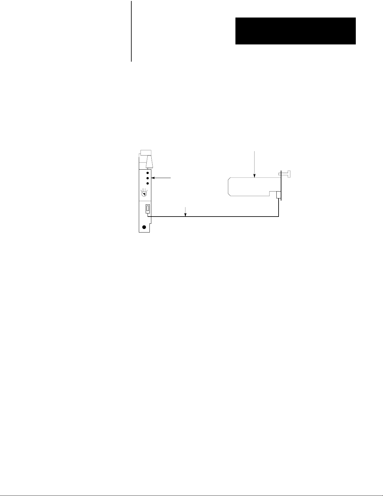
To access the PROM socket, remove the Mini-PLC-2/15 processor module from
the I/O chassis. If you desire to maintain processor memory contents, connect
an external battery pack (Figure 2.3) to the processor with the Mini-Processor
Transport Cable (cat. no. 1772-CD) prior to removing the module from the
chassis.
Figure 2.3
External
Battery Backup
Battery Pack
(Cat. No. 1771BB)
MiniPLC2/15 Processor
(Cat. No. 1772LV)
MiniProcessor
Transport Cable
(Cat. No. 1772CD)
11182
To install the AF4, perform the following steps (Figure 2.2):
1. Turn the mode select switch to PROG.
2. Remove AC power from the I/O chassis power supply.
3. Remove the processor module from the I/O chassis.
4. Check all AF4 pins to ensure they are not bent or dirty.
5. Loosen the screw and lift the PROM door.
6. Push the ON tab in to unlock the socket.
7. Position the AF4 as shown in Figure 2.2. Be sure the notch on your AF4
faces the OFF tab.
8. Line up the AF4 as shown in Figure 2.2 and seat in the socket. Be sure the
pins are aligned as they bend easily.
9. Lock the AF4 in place by pushing the OFF tab in.
10.Close the PROM door and tighten the screw.
23
Page 8

Chapter 2
Installation
Removal
To remove the AF4, perform the following steps:
1. Turn the mode select switch to PROG.
2. To maintain processor memory contents connect an external battery pack
to the processor with the mini-processor transport cable (Figure 2.3).
3. Remove AC power from the I/O chassis power supply.
4. Remove the processor module from the I/O chassis.
5. Loosen the screw, lift up the PROM door, and push the ON tab in to
unlock the socket (Figure 2.2).
6. Carefully remove the AF4 and store it in its shipping container.
24
Page 9

Programming
Chapter
3
General
You access the AF4 by pressing [SHIFT][EAF] (execute auxiliary function) or
[SHIFT][SCT] on the keyboard of your Industrial Terminal (cat. no. 1770-T3).
The instruction is an output instruction and may be preceded on a rung by
condition instructions. Once you enter the function, the block diagram of
Figure 3.1 appears on the CRT. To program a specific mathematics functions,
you would enter the appropriate function number (Table 3.A). If you enter a
non-existent function number, the following occurs:
When the processor attempts to execute a function number which does not exist
on the AF4, the response of the processor depends upon whether the keyswitch
is in the RUN or RUN/PROGRAM position.
The responses are:
In the RUN position, the processor stops running and the CRT displays
PROCESSOR FAULT and CHANGE PROCESSOR TO PROGRAM MODE.
The processor and memory LEDs illuminate. After you change processor
operation to program mode the LEDs turn off and the CRT displays MODE
SELECTION menu and PLC-2 RUN TIME ERROR, PRESS 11 TO
CONTINUE. When you press 11 the CRT displays and intensifies the rung
containing the illegal opcode and states ILLEGAL OPCODE INTENSIFIED
INSTRUCTION LINKED WITH CAUSE OF ERROR.
In the RUN/PROGRAM position, the processor stops running and the CRT
displays MODE SELECTION menu and PLC-2 RUN TIME ERROR, PRESS
11 TO CONTINUE. When you press 11 the CRT displays and intensifies the
rung containing the illegal opcode and states ILLEGAL OPCODE
INTENSIFIED INSTRUCTION LINKED WITH CAUSE OF ERROR.
31
Page 10

Chapter 3
Programming
Table 3.A
Function
Numbers for the AF4
Function
Number
01 Add
02 Subtract
03 Multiply
04 Divide
13 BCD to Binary conversion
14 Binary to BCD conversion
30 Log to base 10
31 Natural log (log to base e)
32 Exponential
33 Power
34 Reciprocal
35 Sine
36 Cosine
37 Square Root
Mathematical Operation
You enter an existent function number and then enter data and result addresses
(we will explain this in detail later). The processor then places a number in the
data address.
AF4 Function Sequence
32
When the Mini-PLC-2/15 controller encounters an AF4 function during
program execution and the rung is true, the processor performs the following
steps:
1. Saves its present position in the user program.
2. The interlock system grants access to the AF4 function.
3. Reads the operand’s data stored in the data address that you entered.
4. Reads the result address which you entered.
5. Determines the location of the mathematical routine requested by the
function number.
6. Executes the routine in the AF4 area. (See Avoiding Excessive AF4
Execution Times.)
7. Writes the results at the result address in the data table.
8. Returns program execution to the next instruction in the user program after
the AF4 function is completed. (See Avoiding Excessive AF4 Execution
Times.)
9. Readies itself for the next AF4 operation.
Page 11

Chapter 3
Programming
AF4 Automatic Checks
To guard against improper program execution, automatic check routines are
incorporated in the AF4. The processor uses these routines to prevent the
following:
Executing AF4 functions having invalid function addresses
Spending so much time executing AF4 functions that the controller neglects
its main program and I/O scans
Invalid
Function Addresses
Valid AF4 function addresses include the I/O image table and the data table
(except word 027). Specifically, valid addresses are from 010 to 026, from 030
to 077, and from 110 to the end of the data table. Result addresses must not
reside in the input image table.
When a user programmed function has an invalid address, the response of the
processor depends upon whether the keyswitch is in the RUN or
RUN/PROGRAM position.
The response are:
In the RUN position, the processor stops running and the CRT displays
PROCESSOR FAULT and CHANGE PROCESSOR TO PROGRAM MODE.
The processor and memory LEDs illuminate. After you change processor
operation to program mode the LEDs turn off and the CRT displays MODE
SELECTION menu and PLC-2 RUN TIME ERROR, PRESS 11 TO
CONTINUE. When you press 11 the CRT displays and intensifies the rung
containing the illegal address and states ILLEGAL ADDRESS INTENSIFIED
INSTRUCTION LINKED WITH CAUSE OF ERROR.
In the RUN/PROGRAM position, the processor stops running and the CRT
displays MODE SELECTION menu and PLC-2 RUN TIME ERROR, PRESS
11 TO CONTINUE. When you press 11 the CRT displays and intensifies the
rung containing the illegal address and states ILLEGAL ADDRESS
INTENSIFIED INSTRUCTION LINKED WITH CAUSE OF ERROR.
33
Page 12

Chapter 3
Programming
A
voiding Excessive AF4 Execution T
Table 3.B lists execution times for AF4 functions. To avoid excessive AF4
function execution times, an interlock system is designed into the AF4. This
system automatically checks and does the following:
Permits no AF4 function to run longer than 6ms without returning processor
scan to the processor.
During a program scan each true AF4 function rung which can be completed
in a single scan will be completed as it is encountered. However, upon
encountering a true AF4 function rung which requires multiple program
scans to complete, all other true AF4 function rungs will be “locked out”
until sufficient program scans complete the active AF4 function rung.
Once started, it completes an AF4 function prior to starting the next AF4
function encountered in the user program which has a true rung condition.
imes
Limits the number of enabled AF4 functions in a program to 50. You may
include more functions but you must ensure that no more than 50 are enabled
at one time. This requirement only applies where you have programmed a
function that requires more than one scan to complete.
This time listed in Table 3.B includes:
Overhead for AF4 interlock system
One run through the portion of the AF4 specified by the particular function
To obtain the time required from activation of the input that makes the rung
containing the AF4 function true until the correct answer for the function is in
the data table, you must add the following times to the values in Table 3.B:
Input delay time (from specification for specific input)
One program scan time and one I/O scan time multiplies by the number of
scans specified in Table 3.B
Methods for determining these times are presented in Mini-PLC-2/15, Series B,
Programmable Controller Programming and Operations Manual (publication
1772- 804).
34
Page 13

Chapter 3
Programming
Table 3.B
Execution T
AF4
Log
Natural log
Function
imes
[1]
Reciprocal
Exponential
Powers
35
Page 14

Chapter 3
Programming
Sine
Function
N
A
W
u
v
o
m
g
r
b
.
s
e
T
t
r
i
T
o
m
i
f
e
m
S
e
c
a
n
s
Cosine
Square Root
00.5
(y
)
BCD to Binary
Binary to BCD
36
Page 15

Function
Addition
Chapter 3
Programming
N
A
W
u
v
o
m
g
r
b
.
s
e
T
t
r
i
T
o
m
i
f
e
m
S
e
c
a
n
s
Subtraction
Multiplication
Division
[1]
These times are calculated for a single AF4 function. Overhead for AF4 lock
maintenance and multiple runs through the ladder program to complete some function is
included.
Programming Specific Mathematical Functions
In this section we explain the following for each of the AF4 functions:
What it is
How to enter it in your program
Its format in the data table
a. word arrangement
37
Page 16

Chapter 3
Programming
b. digit location
Sample entry and display rungs. Although there are several techniques to
enter this data, we use get instructions.
Error messages. If an AF4 function has special error message responses to
specific illegal programming procedures, we state these responses.
38
Page 17

Chapter 3
Programming
Status Bits
The most significant four bits of the most significant word of the result data
area are reserved for status bits. These bits have the following meanings:
Enable - bit 17
Sign - bit 16
Done - bit 15
Error bit - bit 14
The enable bit is set at the start of an AF4 function and reset upon completion.
The sign bit, if set, indicates a negative value.
The done bit is reset at the start of an AF4 function and set upon completion.
The error bit is a general error flag that indicates overflow and invalid operand
or result errors. Individual functions determine the actual state of this bit.
Throughout this manual, unused status bits are shown blank for the following
reasons:
Whether the content of an unused status bit is an input word is 0 or 1 is
irrelevant as such bits are ignored in AF4 function execution.
The AF4 reset unused status bits in result words. For simplicity these bits are
left blank.
Accuracy
In the series A, revision A AF4, the typical error is +
1 in the least significant
digit (LSD). However, two functions have errors which exceed this limit.
Function 32, e
+x
, has error limits of +8 and -1 in the least significant digit for a
range of x from 0.00 to -9.99.
Function 33, y
+x
, has error limits of +6 and -1 in the least significant digit when
x is negative.
AF4 Addition Function
An AF4 addition function operates on two 6-digit BCD numbers and presents
the result in a third 6-digit BCD number.
(+
xxx xxx.) + (+xxx xxx.) = +xxx xxx.
39
Page 18

Chapter 3
Programming
How to enter an AF4 Addition Function
To program an AF4 addition function, perform the following steps:
1. Press [SHIFT][EAF] or [SHIFT][SCT] on the keyboard of your industrial
terminal. Figure 3.1 appears on the CRT
Figure 3.1
Execute
Numbers shown are default values and must be replaced
by your values. The number of default address digits
originally displayed, 3 or 4, depends on the size of the
data table.
Auxiliary Function Format
Execute Aux
Function
Function Number:
Data Addr:
Result Addr:
01
010
010
310
Page 19
Chapter 3
Programming
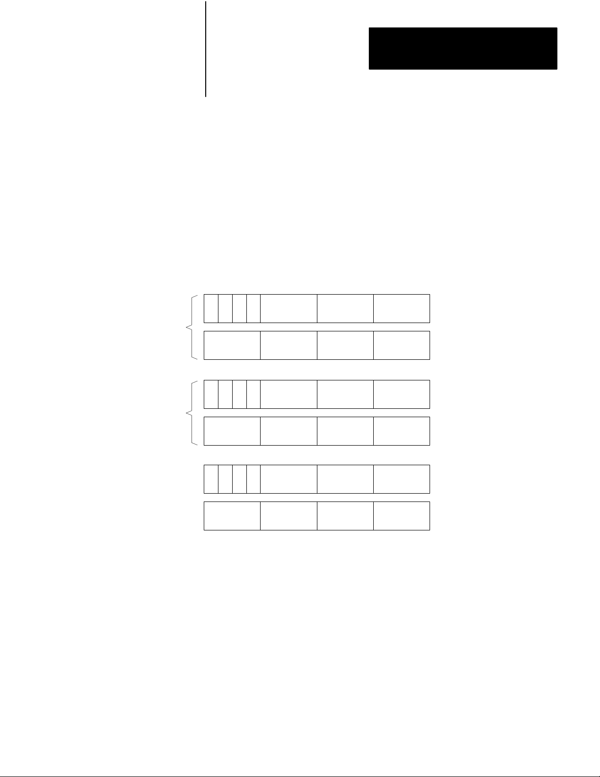
2. Enter 01, the function number for AF4 addition.
This entry identifies that the function entered is to perform an AF4 addition and
that the processor use the data table format shown in Figure 3.2 when executed.
Operands 1 and 2 represent the two 6-digit numbers we wish to add. The six
digits of operand 1 are represented in BCD by the groups of bits labeled digit 1
through 6. Digit 1 and digit 6 are the most significant and the least significant
digits respectively. This digit labeling system also applies to operand 2 and the
result.
Figure 3.2
General
AF4 Addition Function Word and Digit Format
Operand 1
Operand 2
Result
Bit No.
171615141312111076543210
S
S
DERE
S
E = Enable Bit (1 = Function in Progress)
S = Sign Bit (1= Negative)
D = Done Bit (1 = Function Complete)
ER = Error Bit (1 = Overflow)
MSD = Most Significant Digit
LSD = Least Significant Digit
Digit 1
(MSD)
Digit 4
Digit 1
(MSD)
Digit 4
Digit 1
(MSD)
Digit 4
Digit 2 Digit 3
Digit 5
Digit 2 Digit 3
Digit 5
Digit 2 Digit 3
Digit 5
Digit 6
(LSD)
Digit 6
(LSD)
Digit 6
(LSD)
Data Address
m
m + 1
m + 2
m + 3
Result Address
n
n + 1
11481
311
Page 20
Chapter 3
Programming
3. Enter a data address and a result address.
If we select a data address of 201 and a result address of 305, the AF4
establishes the data table format shown in Figure 3.3. Be careful not to select
data and result addresses so close together that the addresses of the operands
following the data address overlap your result address. The data address
eventually contains three digits of operand 1. The AF4 reserves the next three
higher addresses for digits 4 through 6 of operand 1 and digits 1 through 6 of
operand 2. The result address contains the most significant three digits of the
result and the next higher address contains the least significant three digits.
Figure 3.3
AF4
Addition Function Formal After Address Entry
Operand 1
Operand 2
Result
Bit No.
171615141312111076543210
S
S
DERE
S
E = Enable Bit (1 = Function in Progress)
S = Sign Bit (1= Negative)
D = Done Bit (1 = Function Complete)
ER = Error Bit (1 = Overflow)
MSD = Most Significant Digit
LSD = Least Significant Digit
Digit 1
(MSD)
Digit 4
Digit 1
(MSD)
Digit 4
Digit 1
(MSD)
Digit 4
Digit 2 Digit 3
Digit 5
Digit 2 Digit 3
Digit 5
Digit 2 Digit 3
Digit 5
Digit 6
(LSD)
Digit 6
(LSD)
Digit 6
(LSD)
Data Address
201
202
203
204
Result Address
305
306
11482
312
Page 21

Chapter 3
Programming
4. Enter values for operands 1 and 2.
You can enter these values from the keyboard of your industrial terminal or
through ladder diagram functions. Entry of operand 1 - 102746 and operand 2 256384 produces the result 359130 when the addition function executes.
Figure 3.4 shows how the result is stored.
Figure 3.4
Addition Function Format After Execution
AF4
Operand 1
Operand 2
Result
Bit No
171615141312111076543210
S
(0)
S
(0)
S
(0) (0) (1) (0)
E = Enable Bit (1 = Function in Progress)
S = Sign Bit (1= Negative)
D = Done Bit (1 = Function Complete)
ER = Error Bit (1 = Overflow)
DERE
1
02
467
562
843
593
301
Data Address
Word 201
Word 202
Word 203
Word 204
Result Address
Word 305
Word 306
11483
Entry and Display of Input and Result Values
Figure 3.5 shows one method for inserting input values and displaying input
values and results of AF4 addition computations. Although there are several
techniques for accomplishing this, we chose get instructions. The first rung
requests an AF4 addition. The second rung shows the two operands in its top
branch and the resultant sum in its lower branch.
313
Page 22

Chapter 3
Programming
Figure 3.5
Addition Function Input and Result Display Rungs
AF4
Execute Aux
Function
Function Number:
Data Addr:
Result Addr:
01
201
305
201
202
203
204
G
G
G
G
102
746
256
384
305
306
G
G
359
130
Error Message
If the resultant sum has more than six integers, the error bit (bit 14) is set
indicating overflow.
AF4
Subtraction Function
An AF4 subtraction function operates on two 6-digit BCD numbers and
presents the result in a third 6-digit BCD number.
(+
xxx xxx/ - +xxx xxx.) = +xxx xxx.
How to Enter an AF4 Subtraction Function
Storage
Bit
314
To program an AF4 subtraction function, perform the following steps:
1. Press [SHIFT][EAF] or [SHIFT][SCT] on the keyboard of your industrial
terminal. Figure 3.1 appears on the CRT.
2. Enter 02, the function number for AF4 subtraction.
This entry identifies that the function entered is to perform an AF4 subtraction
and that the processor use the data table format shown in Figure 3.6 when
executed. Operands 1 and 2 represent the two 6-digit numbers whose difference
you want to find. The six digits of operand 1 are represented in BCD by the
group of bits labeled digit 1 through 6. Digit 1 and digit 6 are the most
significant and the least significant digits respectively. This digit labeling
system also applies to operand 2 and the result.
Page 23

Figure 3.6
AF4 Subtraction Function Word Digit Format
General
Chapter 3
Programming
Operand 1
Operand 2
Result
Bit No.
171615141312111076543210
S
S
DERE
S
E = Enable Bit (1 = Function in Progress)
S = Sign Bit (1= Negative)
D = Done Bit (1 = Function Complete)
ER = Error Bit (1 = Overflow)
MSD = Most Significant Digit
LSD = Least Significant Digit
Digit 1
(MSD)
Digit 4
Digit 1
(MSD)
Digit 4
Digit 1
(MSD)
Digit 4
Digit 2 Digit 3
Digit 5
Digit 2 Digit 3
Digit 5
Digit 2 Digit 3
Digit 5
Digit 6
(LSD)
Digit 6
(LSD)
Digit 6
(LSD)
Data Address
m
m + 1
m + 2
m + 3
Result Address
n
n + 1
11484
3. Enter a data address and a result address.
If we select a data address of 201 and a result address of 305, the AF4
establishes the data table format shown in Figure 3.7. The data address
eventually contains three digits of operand 2. The AF4 reserves the next three
higher addresses for digits 4 through 6 of operand 1 and digits 1 through 6 of
operand 2. The result address contains the most significant three digits of the
result and the next higher address contains the least significant three digits.
315
Page 24

Chapter 3
Programming
Figure 3.7
Subtraction Function Format After Address Entry
AF4
Operand 1
Operand 2
Result
Bit No.
171615141312111076543210
S
S
DERE
S
E = Enable Bit (1 = Function in Progress)
S = Sign Bit (1= Negative)
D = Done Bit (1 = Function Complete)
ER = Error Bit (1 = Overflow)
MSD = Most Significant Digit
LSD = Least Significant Digit
Digit 1
(MSD)
Digit 4
Digit 1
(MSD)
Digit 4
Digit 1
(MSD)
Digit 4
Digit 2 Digit 3
Digit 5
Digit 2 Digit 3
Digit 5
Digit 2 Digit 3
Digit 5
Digit 6
(LSD)
Digit 6
(LSD)
Digit 6
(LSD)
Data Address
201
202
203
204
Result Address
305
306
11485
316
4. Enter values for operands 1 and 2.
You can enter these values form the keyboard of your industrial terminal or
through ladder diagram functions. Entry of operand 1 = 102746 and operand 2
256384 produces the result -153638 when the subtraction function executes.
Figure 3.8 shows how the result is stored.
Page 25

Operand 1
Bit No
Chapter 3
Programming
Figure 3.8
Subtraction Function Format After Execution
AF4
17 16 15 14 13 12 11 10 7 6 5 4 3 2 1 0
(0)
S
1
02
467
Data Address
201
202
Operand 2
Result
S
(0)
DERE
S
(0) (0) (1) (0)
E = Enable Bit (1 = Function in Progress)
S = Sign Bit (1= Negative)
D = Done Bit (1 = Function Complete)
ER = Error Bit (1 = Overflow)
562
843
531
386
203
204
Result Address
305
306
11486
Entry and Display of Input and Result Values
Figure 3.9 shows one method of inserting input values and displaying input
values and results of AF4 subtraction computations. Although there are several
techniques for accomplishing this, we chose get instructions. The first rung
requests an AF4 subtraction. The second rung shows the two operands in its top
branch and the resultant difference in its lower branch.
Figure 3.9
Af4
Subtraction Function Input and Result Display Rungs
201
202
203
204
G
G
G
G
102
746
256
384
305
306
G
G
153
638
Execute Aux
Function
Function Number:
Data Addr:
Result Addr:
02
201
305
Storage
Bit
317
Page 26

Chapter 3
Programming
Error Message
If the result has more than six integers, the error bit (bit 14) is set indicating
overflow.
AF4
Multiplication Function
An AF4 multiplication function operates on two 6-digit BCD numbers and
presents the results in a 12-digit BCD number.
(+
xxx xxx.) x (+xxx xxx.) = +xxx xxx xxx xxx.
How to Enter an AF4 Multiplication Function
To program an AF4 multiplication function, perform the following steps:
1. Press [SHIFT][EAF] or [SHIFT][SCT] on the keyboard of your industrial
terminal. Figure 3.1 appears on the CRT.
2. Enter 03, the function number for AF4 multiplication.
This entry identifies that the function entered is to perform an AF4
multiplication and that the processor use the data table format shown in
Figure 3.10 when executed. Operands 1 and 2 represent two 6-digit numbers
whose product you want to find. The six digits of operand 1 are represented in
BCD by groups of bits labeled digit 1 through 6. Digit 1 and 6 are the most
significant and least significant digits respectively. Operand 2 and the 12 digits
of the result are labeled similarly.
318
Page 27

Figure 3.10
AF4 Multiplication Function Word and Digit Format
General
Chapter 3
Programming
Bit No.
Operand 1
Operand 2
Result
171615141312111076543210
S
S
S
Digit 1
(MSD)
Digit 4
Digit 1
(MSD)
Digit 4
DE
Digit 1
(MSD)
Digit 7
Digit 2 Digit 3
Digit 5
Digit 2 Digit 3
Digit 5
Digit 2 Digit 3
Digit 5Digit 4
Digit 8 Digit 9
Digit 6
(LSD)
Digit 6
(LSD)
Digit 6
Data Address
m
m + 1
m + 2
m + 3
Result Address
n
n + 1
n + 2
Digit 10
E = Enable Bit (1 = Function in Progress)
S = Sign Bit (1= Negative)
D = Done Bit (1 = Function Complete)
MSD = Most Significant Digit
LSD = Least Significant Digit
Digit 11
Digit 12
(LSD)
n + 3
11487
3. Enter a data address and a result address.
If we enter a data address of 201 and a result address of 305, the AF4
establishes the data table format shown in Figure 3.11. The data address
eventually contains the most significant three digits of operand 1. The AF4
reserves the next three higher addresses for the least significant three digits of
operand 1 and the six digits of operand 2. The result address contains the most
significant three digits of the result. The AF4 reserves the next three higher
addresses for the remaining nine digits of the result.
319
Page 28

Chapter 3
Programming
Figure 3.11
Multiplication Function format After Address Entry
AF4
Bit No.
Operand 1
Operand 2
Result
171615141312111076543210
S
S
S
DE
Digit 1
(MSD)
Digit 4
Digit 1
(MSD)
Digit 4
Digit 1
(MSD)
Digit 7
Digit 2 Digit 3
Digit 5
Digit 2 Digit 3
Digit 5
Digit 2 Digit 3
Digit 5Digit 4
Digit 8 Digit 9
Digit 6
(LSD)
Digit 6
(LSD)
Digit 6
Data Address
201
202
203
204
Result Address
305
306
307
Digit 10
E = Enable Bit (1 = Function in Progress)
S = Sign Bit (1= Negative)
D = Done Bit (1 = Function Complete)
MSD = Most Significant Digit
LSD = Least Significant Digit
Digit 11
Digit 12
(LSD)
310
11488
320
Page 29

Chapter 3
Programming
4. Enter values for operands 1 and 2.
You can enter these values from the keyboard of your industrial terminal or
through ladder diagram functions. Entry of operand 1 - 000400 and operand 2 000200 produces the result 00000080000 (Figure 3.12).
Figure 3.12
AF4
Multiplication Function Format After Execution
Bit No.
Operand 1
Operand 2
Result
171615141312111076 54 3 2 1 0
S
(0)
S
(0)
S
(0)(0)(1)
DE
0
00
004
000
002
000
000
800
000
Data Address
201
202
203
204
Result Address
305
306
307
310
E = Enable Bit (1 = Function in Progress)
S = Sign Bit (1= Negative)
D = Done Bit (1 = Function Complete)
11489
Entry and Display of Input and Result Values
Figure 3.13 shows one method you can use to enter values for operands 1 and 2
and for displaying the results of an AF4 multiplication. Although there are
several techniques for accomplishing this, we chose get instructions. The first
rung requests an AF4 multiplication. The top branch of the second rung shows
the two 6-digit operands while the lower branch shows the 12 digit product.
321
Page 30

Chapter 3
Programming
Figure 3.13
Multiplication Function Input and Result Display Rungs
Af4
Execute Aux
Function
Function Number:
Data Addr:
Result Addr:
03
201
305
201
202
203
204
G
G
G
G
000
400
000
200
305
306
306
306
G
G
G
G
153
638
638
638
AF4 Division Function
An AF4 division function operates on two 6-digit BCD numbers and presents
the results in a 12-digit BCD number.
(+
xxx xxx.) : (+xxx xxx.) = +xxx xxx.xxx xxx
How to Enter an AF4 Division Function
To program an AF4 division function, perform the following steps:
1. Press [SHIFT][EAF] or [SHIFT][SCT] on the keyboard of your industrial
terminal. Figure 3.1 appears on the CRT.
Storage
Bit
322
2. Enter 04, the function number for AF4 division.
This entry identifies that the function entered is to perform an AF4 division and
that the processor use the data table format shown in Figure 3.14 when
executed. Operands 1 and 2 represent two 6-digit numbers whose quotient you
wish to find. The six digits of operand 1 are represented in BCD by groups of
bits labeled digit 1 through 6. Digit 1 and 6 are the most significant and least
significant digits respectively. Operand 2 and the 12 digits of the result are
labeled similarly.
Page 31

Figure 3.14
AF4 Division Function W
General
Chapter 3
Programming
ord and Digit Format
Bit No.
Operand 1
Operand 2
Result
17161514131211107 6 5 4 3 2 1 0
ER
Digit 1
(MSD)
Digit 4
Digit 1
(MSD)
Digit 4
Digit 1
(MSD)
Digit 7
Digit 10
S
S
DE
S
Digit 2 Digit 3
Digit 5
Digit 2 Digit 3
Digit 5
Digit 2 Digit 3
Digit 5Digit 4
Digit 8 Digit 9
Digit 11
Digit 6
(LSD)
Digit 6
(LSD)
Digit 6
Digit 12
(LSD)
Data Address
m
m + 1
m + 2
m + 3
Result Address
n
n + 1
n + 2
n + 3
E = Enable Bit (1 = Function in Progress)
S = Sign Bit (1= Negative)
D = Done Bit (1 = Function Complete)
ER = Illegal Operand (Divide by Zero)
MSD = Most Significant Digit
LSD = Least Significant Digit
11490
3. Enter a data address and a result address.
If we enter a data address of 201 and a result address of 305, the AF4
establishes the data table format shown in Figure 3.15. The data address
eventually contains the most significant three digits of operand 1. The AF4
reserves the next three higher addresses for the least significant three digits of
operand 1 and the six digits of operand 2. The result address contains the most
significant three digits of the result. The AF4 reserves the next three higher
addresses for the remaining nine digits of the result.
323
Page 32

Chapter 3
Programming
Figure 3.15
Division Function Format After Address Entry
AF4
Bit No.
Operand 1
Operand 2
Result
171615141312111076543210
ER
Digit 1
(MSD)
Digit 4
Digit 1
(MSD)
Digit 4
Digit 1
(MSD)
Digit 7
Digit 10
Digit 2 Digit 3
Digit 5
Digit 2 Digit 3
Digit 5
Digit 2 Digit 3
Digit 5Digit 4
Digit 8 Digit 9
Digit 11
Digit 6
(LSD)
Digit 6
(LSD)
Digit 6
Digit 12
(LSD)
S
S
S
DE
Data Address
201
202
203
204
Result Address
305
306
307
310
E = Enable Bit (1 = Function in Progress)
S = Sign Bit (1= Negative)
D = Done Bit (1 = Function Complete)
ER = Illegal Operand (Divide by Zero)
MSD = Most Significant Digit
LSD = Least Significant Digit
11491
324
Page 33

Chapter 3
Programming
4. Enter values for operands 1 and 2.
You can enter these numbers from the keyboard of your industrial terminal or
through ladder diagram functions. Entry of operand 1 = 000400 and operand 2
- 000200 produces the result 000002.000000 (Figure 3.16).
Figure 3.16
AF4
Division Function Format After Execution
Bit No.
Operand 1
Operand 2
Result
171615141312111076 54 3 2 1 0
S
(0)
S
(0)
DE
S
(0)(0)(1)ER(0)
0
00
004
000
002
000
020
000
000
Data Address
201
202
203
204
Result Address
305
306
307
310
E = Enable Bit (1 = Function in Progress)
S = Sign Bit (1= Negative)
D = Done Bit (1 = Function Complete)
ER = Illegal Operand (Divide by Zero)
11492
Entry and Display of Input and Result Values
Figure 3.17 shows one method you can use to enter values for operands 1 and 2
and for displaying the results of an AF4 division. Although there are several
techniques for accomplishing this, we chose get instructions. The first rung
requests an AF4 division function. The top branch of the second rung shows
the two 6-digit operands while the lower branch shows the 12 digit quotient.
325
Page 34

Chapter 3
Programming
Figure 3.17
Division Function Input and Result Display Rungs
AF4
Execute Aux
Function
Function Number:
Data Addr:
Result Addr:
04
201
305
201
202
203
204
G
G
G
G
000
400
000
200
305
306
306
306
G
G
G
G
000
002
000
000
Error Message
If you divide by zero, the error bit (bit 14) is set and the result reads zero.
AF4 BCD to Binary Conversion Function
The AF4 BCD (binary coded decimal) to binary conversion function converts a
BCD number (from 0 to 4095) into a 12-bit binary number.
How to Enter an AF4 BCD to Binary Conversion Function
To program an AF4 BCD to binary conversion function, perform the following
steps:
Storage
Bit
326
1. Press [SHIFT][EAF] or [SHIFT][SCT] on the industrial terminal
keyboard. Figure 3.1 appears on the CRT.
Page 35

Chapter 3
Programming
2. Enter 13, the function number for AF4 BCD to binary conversion.
This entry identifies that the function entered is to perform an AF4 BCD to
binary conversion and that the processor use the data table format shown in
Figure 3.18 when executed.
Figure 3.18
General
AF4 BCD to Binary Conversion Function Word and Digit Format
Bit No.
Operand
Result
171615141312111076543210
DE
Digit 1 (MSD)
(Always = 0)
Digit 4
ER
S
S
E = Enable Bit (1 = Function in Progress)
S = Sign Bit (1= Negative)
D = Done Bit (1 = Function Complete)
ER = Error Bit (1 = BCD Number > 4095 Entered)
MSD = Most Significant Digit
LSD = Least Significant Digit
Digit 2
(Always = 0)
Digit 5
Digit 3
(Must be 3 4)
Digit 6
(LSD)
Data Address
m
m + 1
Result Address
n
11493
3. Enter a data address and a result address.
If we choose a data address of 200 and a result address of 300, the data table
format is as shown in Figure 3.19. The most significant three digits of the
operand (the BCD number we want to convert to binary) reside in the data
address word 200 and the least significant three digits reside in the next higher
address, 201. The first two digits are always zero and the third digit must not
exceed four. The number, converted to binary format, is stored in bits 0 through
13 in the result address, word 300.
Figure 3.19
AF4
BCD to Binary Conversion Function Format After Address Only
Bit No.
Operand
Result
17 16 15 14 13 12 11 10 7 6 5 4 3 2 1 0
Digit 2
(Always = 0)
Digit 5
(Must be
DE
Digit 1 (MSD)
(Always = 0)
Digit 4
ER
S
S
E = Enable Bit (1 = Function in Progress)
S = Sign Bit (1= Negative)
D = Done Bit (1 = Function Complete)
ER = Error Bit (1 = BCD Number > 4095 Entered)
MSD = Most Significant Digit
LSD = Least Significant Digit
Digit 3
Digit 6
(LSD)
3 4)
Data Address
200
201
Result Address
300
11494
327
Page 36

Chapter 3
Programming
Bit No.
Operand
4. Enter the operand.
You can enter the operand from the keyboard of your industrial terminal or
through ladder diagram functions. If we choose to enter 4095, the largest BCD
number that we can convert to a 12 bit binary number, we obtain the data table
configuration shown in Figure 3.20.
Figure 3.20
Af4
BCD to Binary Conversion Function Format After Execution
17 16 15 14 13 12 11 10 7 6 5 4 3 2 1 0
Data Address
200
(0)
S
004
201
Result Address
300
11495
Result
095
S
ER
DE
(0) (0) (1) (0)
E = Enable Bit (1 = Function in Progress)
S = Sign Bit (1= Negative)
D = Done Bit (1 = Function Complete)
ER = Error Bit (1 = BCD Number > 4095 Entered)
111111111111
Entry and Display of Input and Result Values
Figure 3.21 shows one method for inserting input values and displaying inputs
and results of an AF4 BCD to binary conversion. Although there are other
methods for accomplishing this, we chose get instructions. The first rung
requests an AF4 BCD to binary conversion. The top branch of the second rung
shows the BCD number we want to convert (004095) in words 200 and 201.
The bottom branch shows in the hexadecimal notation FFF (bits 0 through 13 in
word 300 have the states shown in Figure 3.20).
Figure 3.21
AF4
BCD to Binary Conversion Function Input and Display Rungs
Execute Aux
Function
200
004
300
FFF
Function Number:
Data Addr:
Result Addr:
201
G
G
G
095
13
200
300
Storage
Bit
328
Page 37

Chapter 3
Programming
Error Message
If you enter a BCD number larger than 4095, the error bit (bit 14) is set and the
result reads zero.
AF4 Binary to BCD Conversion Function
The AF4 binary to BCD conversion function converts a 12-bit binary number to
a BCD number (from 0 to 4095).
How to Enter an AF4 Binary to BCD Conversion Function
To program an AF4 binary to BCD conversion function, perform the following
steps:
1. Press [SHIFT][EAF]or [SHIFT][SCT] on the keyboard of your industrial
terminal. Figure 3.1 appears on the CRT.
Bit No.
Operand
2. Enter 14, the function number for the AF4 binary to BCD conversion.
This entry identifies that the function entered is to perform an AF4 binary to
BCD conversion and that the processor use the data table format shown in
Figure 3.22 when executed.
Figure 3.22
General
AF4 Binary to BCD Conversion Function Word and Digit Format
171615141312111076543210
S
Digit 1 (MSD)
DE
S
E = Enable Bit (1 = Function in Progress)
S = Sign Bit (1= Negative)
D = Done Bit (1 = Function Complete)
MSD = Most Significant Digit
LSD = Least Significant Digit
(Always = 0)
Digit 4
12 Bit Binary Number
Digit 2
(Always = 0)
Digit 5
Digit 3
Digit 6
(LSD)
Data Address
m
Result AddressResult
n
n + 1
11496
3. Enter a data address and a result address.
If we choose a data address of 200 and a result address of 300, the data table
format is as shown in Figure 3.23. Bits 0 through 13 or word 200 are reserved
for the operand (the 12-bit binary number we want to convert to BDD). The
result address, 300, contains the most significant three digits of the resulting
BCD number and the least significant three digits reside in the next higher
address, 301. The first two digits of the BCD number are always zero and the
third digit can not exceed four.
329
Page 38

Chapter 3
Programming
Figure 3.23
Binary to BCD Conversion Function Format After Address Entry
AF4
Bit No.
Operand
171615141312111076543210
Data Address
S
Digit 1 (MSD)
DE
S
E = Enable Bit (1 = Function in Progress)
S = Sign Bit (1= Negative)
D = Done Bit (1 = Function Complete)
MSD = Most Significant Digit
LSD = Least Significant Digit
(Always = 0)
Digit 4
12 Bit Binary Number
(Always = 0)
Digit 2
Digit 5
Digit 3
Digit 6
(LSD)
200
Result AddressResult
300
301
11497
4. Enter the operand.
You can enter the operand from the keyboard of your industrial terminal or
through ladder diagram functions. If we choose to set bits 0 through 13 in word
200, that is, insert the largest possible binary number in 12 bits, we obtain 4095
for the corresponding BCD number (Figure 3.24). The ones in bits 0 through
13 of word 200 indicate that each bit is set.
330
Bit No.
Operand
Result
Figure 3.24
AF4
Binary to BCD Conversion Function Format After Execution
17 16 15 14 13 12 11 10 7 6 5 4 3 2 1 0
S
S
(0) (0) (1)
E = Enable Bit (1 = Function in Progress)
S = Sign Bit (1= Negative)
D = Done Bit (1 = Function Complete)
11 11 11 11 11 11
DE
004
095
Data Address
200
Result Address
300
301
11498
Page 39

Chapter 3
Programming
Entry and Display of Input and Result Values
Figure 3.25 shows one method for inserting input values and displaying inputs
and results of an AF4 binary to BCD conversion function. Although there are
other methods for accomplishing this, we chose get instructions. The first rung
requests an AF4 binary to BCD conversion function. The top branch of the
second rung shows the binary number (in the hexadecimal notation FFF) that
we want converted to BCD. In this example, the binary number is the largest
possible, with bits 0 through 13 of word 200 set as shown in figure 3.24. The
lower branch shows the resulting BCD number, 004095, in words 300 and 301.
Figure 3.25
AF4 Binary to BCD Conversion Function Input and Result Display Rungs
Execute Aux
Function
200
G
004
300
FFF
Function Number:
Data Addr:
Result Addr:
201
G
G
095
14
200
300
Storage
Bit
Sign Bits
If you encounter any binary data where the sign bit is not in bit 16, you must
move the sign bit into bit 16 of an auxiliary data table word prior to doing a
binary to BCD conversion. If, for example, the sign bit of your module is bit 15
in word 200, the rungs in Figure 3.26 permit you to make a binary to BCD
conversion. The first rung puts word 200 data into word 201. Rung two sets bit
16 in word 201 if bit 15 in word 200 is set. The AF4 binary to BCD conversion
function in rung three then uses word 201 as its data address.
331
Page 40

Chapter 3
Programming
Figure 3.26
Transfer
200
G
200
15
of Sign Bit
Execute Aux
Function
Function Number:
Data Addr:
Result Addr:
14
201
AF4 Log to Base 10 Function
The AF4 log to the base 10 function finds the log of a 3-digit BCD integer. The
result is a 6-digit BCD number with an implied decimal point after the most
significant digit.
201
PUT
201
PUT
16
log (xxx.) - x.xx xxx
How to Enter an AF4 Log to Base 10 Function
To program an AF4 log to base 10 function perform the following steps:
1. Press [SHIFT][EAF] or [SHIFT][SCT] on the keyboard of your industrial
terminal. Figure 3.1 appears in the CRT.
2. Enter 30, the function number for an AF4 log to base 10 function.
This entry identifies that the function entered is to perform an AF4 log to base
10 calculation and that the processor use the data table format shown in
Figure 3.27 when executed. The three digits of the number whose log you want
are represented in BCD by the digits labeled 1 through 3 in the operand. The
6-digit result is represented by digits labeled 1 through 6. The most significant
digit (MSD) and least significant digit (LSD) are labeled.
332
Page 41

Figure 3.27
AF4 Log to Base 10 Function W
General
Chapter 3
Programming
ord and Digit Format
Bit No.
Operand
Result
171615141312111076543210
Digit 1
(MSD)
ER
Digit 1
(MSD)
Digit 4
DE
E = Enable Bit (1 = Function in Progress)
D = Done Bit (1 = Function Complete)
ER = Error Bit (1 = Input is 0)
MSD = Most Significant Digit
LSD = Least Significant Digit
Digit 2
Digit 2
Digit 5
Digit 3
(LSD)
Digit 3
Digit 6
(LSD)
Data Address
m
Result Address
n
n + 1
11499
3. Enter a data address and a result address.
If we select a data address of 201 and a result address of 305, the AF4
establishes the data table format shown in Figure 3.28. The data address is
reserved for the three digits of the number whose log you want. The result
address, 305, is reserved for the first three digits of the resultant log; the next
higher address, 306, is reserved for the last three digits. The implied decimal
point in the result is after the MSD.
Bit No.
Operand
Result
Figure 3.28
AF4
Log to Base 10 Function Format After Address Entry
171615141312111076543210
Digit 1
(MSD)
DE
ER
E = Enable Bit (1 = Function in Progress)
D = Done Bit (1 = Function Complete)
ER = Error Bit (1 = Input is 0)
MSD = Most Significant Digit
LSD = Least Significant Digit
Digit 1
(MSD)
Digit 4
Digit 2
Digit 2
Digit 5
Digit 3
(LSD)
Digit 3
Digit 6
(LSD)
Data Address
201
Result Address
305
306
11500
333
Page 42

Chapter 3
Programming
Operand
4. Enter the operand.
You can enter the operand from the keyboard of your industrial terminal or
through ladder diagram functions. Entry of operand - 648 produces the result
2.81157 when the log function executes. Figure 3.29 shows how the result is
stored.
Figure 3.29
AF4 Log to Base 10 Function Format After Execution
171615141312111076543210Bit No.
648
Data Address
201
Result Address
305
306
Result
ER
(0) (1)
E = Enable Bit (1 = Function in Progress)
D = Done Bit (1 = Function Complete)
ER = Error Bit (1 = Input is 0)
DE
(0)
281
157
Entry and Display of Input and Result Values
Figure 3.30 shows one method for inserting the operand and displaying the
input value and result of an AF4 log to base 10 function. Although there are
several techniques for accomplishing this, we chose get instructions. The first
rung requests an AF4 log to base 10 function. The second rung shows the
operand 648 in word 201 in the upper branch and the desired log 2.81157 in
words 305 and 306 in the lower branch.
Figure 3.30
AF4 Log to Base 10 Function Input and Result Display Rungs
Execute Aux
Function
Function Number:
Data Addr:
Result Addr:
201
305
11507
30
334
201
G
648
305
G
281
Storage
Bit
306
G
157
Page 43

Chapter 3
Programming
Error Messages
If you try to find the log of zero, the error bit is set and the result is zero.
AF4 Natural Log Functions
The AF4 natural log function finds the natural log of a 3-digit BCD integer to
the base e. The result is a 6-digit BCD value with an implied decimal point after
the most significant digit.
In (xxx.) - x.xx xxx
How to Enter an AF4 Natural Log Function
To program an AF4 natural log function, perform the following steps:
1. Press [SHIFT][EAF] or [SHIFT][SCT] on the keyboard of your industrial
terminal. Figure 3.1 appears on the CRT.
Bit No.
Operand
Result
2. Enter 31, the function number for the AF4 natural log function.
This entry identifies that the function entered is to perform an AF4 natural log
calculation and that the processor use the data table format shown in
Figure 3.31 when executed. The three digits of the operand (the number whose
natural log you want) and represented in BCD by the groups of bits labeled digit
1 through 3. The six digits of the result are labeled digit 1 through 6. A decimal
point is implied after the MSD.
Figure 3.31
General
AF4 Natural Log Function Word and Digit Format
171615141312111076543210
Digit 1
(MSD)
ER
Digit 1
(MSD)
Digit 4
DE
E = Enable Bit (1 = Function in Progress)
D = Done Bit (1 = Function Complete)
ER = Error Bit (1 = Input is 0)
MSD = Most Significant Digit
LSD = Least Significant Digit
Digit 2
Digit 2
Digit 5
Digit 3
(LSD)
Digit 3
Digit 6
(LSD)
Data Address
m
Result Address
n
n + 1
11501
3. Enter a data address and a result address.
335
Page 44

Chapter 3
Programming
If we enter a data address of 201 and a result address of 305, the AF4
establishes the data table format shown in Figure 3.32. The data address
eventually contains the operand. The result address (word 305) contains the first
three digits of the result and word 306 contains the last three digits.
Figure 3.32
AF4 Natural Log Function Format After Address Entry
Bit No.
Operand
Result
171615141312111076543210
Digit 1
(MSD)
ER
Digit 1
(MSD)
Digit 4
DE
E = Enable Bit (1 = Function in Progress)
D = Done Bit (1 = Function Complete)
ER = Error Bit (1 = Input is 0)
MSD = Most Significant Digit
LSD = Least Significant Digit
Digit 2
Digit 2
Digit 5
Digit 3
(LSD)
Digit 3
Digit 6
(LSD)
Data Address
201
Result Address
305
306
11502
4. Enter the number for the operand.
You can enter this number from the keyboard of your industrial terminal or
through ladder diagram functions. Entry of operand = 648 produces the result
6.47389 when the natural log function executes. Figure 3.33 shows how the
result is stored.
336
Operand
Result
Figure 3.33
AF4
Natural Log Function Format After Execution
171615141312111076543210Bit No.
64 8
DE
(0) (1) (0)
ER
E = Enable Bit (1 = Function in Progress)
D = Done Bit (1 = Function Complete)
ER = Illegal Operand (1 = Input is 0)
64 7
38 9
Data Address
201
Result Address
305
306
11503
Page 45

Chapter 3
Programming
Entry and Display of Input and Result Values
Figure 3.34 shows one method for inserting the operand and displaying the
input value and result of an AF4 natural log function. Although there are
several techniques for accomplishing this, we chose get instructions. The first
rung requests an AF4 natural log function. The second rung shows the operand
648 in word 201 in the upper branch and the desired natural log 6.47389 in
words 305 and 306 in the lower branch.
Figure 3.34
AF4 Natural Log Function Input and Result Display Rungs
Execute Aux
Function
Function Number:
Data Addr:
Result Addr:
31
201
305
201
G
648
305
G
647
306
G
389
Storage
Error Messages
If you try to find the natural log of zero, the error bit is set and the result is zero.
AF4 Exponential Function
The AF4 exponential function finds the value of the exponential function ex.
The result is in terms of a base number r and a power of 10, s, by which the base
number is multiplied to obtain the exponential function value. The equation is:
+x
e
=r(10)
s
where:
x= +
X.XX
r = resultant base number = X.XX
Bit
s = the exponent of 10 = +
X.
How to Enter an AF4 Exponential Function
To program an AF4 exponential perform the following steps:
1. Press [SHIFT][EAF] or [SHIFT][SCT] on the keyboard of your industrial
terminal. Figure 3.1 appears on the CRT.
337
Page 46

Chapter 3
Programming
2. Enter 32, the function number for an AF4 exponential function.
This entry identifies that the function entered is to perform an AF4 exponential
calculation and that the processor use the data table format shown in
Figure 3.35 when executed.
Figure 3.35
General AF4 Exponential Function W
ord and Digit Format
Bit No.
Operand
Result Base r
s (Power of 10)
171615141312111076543210
S
DE
S
E = Enable Bit (1 = Function in Progress)
S = Sign Bit (1 = Negative)
D = Done Bit (1 = Function Complete)
MSD = Most Significant Digit
LSD = Least Significant Digit
Digit 1
(MSD)
Digit 1
(MSD)
Digit 1 (MSD) Digit 3
(Always = 0) (Always = 0)
Digit 2
Digit 2
Digit 2
Digit 3
(LSD)
Digit 3
(LSD)
(LSD)
Data Address
m
Result Address
n
n + 1
11504
3. Enter a data address and a result address.
If we choose a data address of 200 and a result address of 305, the AF4
establishes the data table format shown in Figure 3.36. The three digits of the
word 200 are reserved for the operand (the power to which e is being raised).
The result address is reserved for the three digits of 4, the base number of the
answer with an implied decimal after the MSD. The next higher address, word
306, is reserved for s, the power of 10. The implied decimal point of exponent s
is after the LSD; the MSD and digit 2 are always zero. The base number r is
accurate to +
.01.
338
Figure 3.36
AF4 Exponential Function Format After Address Entry
Bit No.
Operand
s (Power of 10)
17 16 15 14 13 12 11 10 7 6 5 4 3 2 1 0
S
DE
S
E = Enable Bit (1 = Function in Progress)
S = Sign Bit (1 = Negative)
D = Done Bit (1 = Function Complete)
MSD = Most Significant Digit
LSD = Least Significant Digit
Digit 1
(MSD)
Digit 1
(MSD)
Digit 1 (MSD) Digit 3
(Always = 0) (Always = 0)
Digit 2
Digit 2
Digit 2
Digit 3
(LSD)
Digit 3
(LSD)
(LSD)
Data Address
200
Result AddressResult Base r
305
306
11505
Page 47

Operand
Chapter 3
Programming
4. Enter the operand.
You can enter the operand from the keyboard of your industrial terminal or
through ladder diagram functions. Entry of an operand (exponent) of e) of 9.42
yields an exponential function value of 1.23(10)
305 and the exponent of ten resides in word 306 as shown in Figure 3.37.
Figure 3.37
AF4 Exponential Function Format After Execution
171615141312111076543210Bit No.
S
(0)
942
004
. The base r resides in word
Data Address
200
s (Power of 10)
(0) (1)
DE
S
(0)
E = Enable Bit (1 = Function in Progress)
S = Sign Bit (1 = Negative)
D = Done Bit (1 = Function Complete)
123
004
Result AddressResult Base r
305
306
11506
Entry and Display of Input and Result Values
Figure 3.38 shows one method for inserting input values and displaying input
values and results of an AF4 exponential function. Although there are several
techniques for accomplishing this, we chose get instructions. The first rung
requests execution of an AF4 exponential function. The second rung contains
9.42, the exponent of e in word 200 with an implied decimal point after the first
digit. It also shows the result, (1.23)(10)
004
, in the form of 123 in word 305 and
004 in word 206. The decimal points are implied.
Figure 3.38
AF4
Exponential Function Input and Result Display Rungs
201
G
648
305
G
647
306
G
389
Execute Aux
Function
Function Number:
Data Addr:
Result Addr: 305
32
Storage
Bit
339
Page 48

Chapter 3
Programming
AF4 Power Function
The AF4 power function evaluates y+
x and gives the result in terms of a base
number r and a power of 10, s, by which you multiply this base number to
obtain the power function value. The equation is:
y+
x = r(10)
+s
where:
y = input base = XXX.
x = input exponent = XX.X
r = result base = X.XX
s = resultant exponent = +
XX. (The first digit is always zero)
A request for zero to the zero power will result in plus one.
How to Enter an AF4 Power Function
To program an AF4 power function perform the following steps:
1. Press [SHIFT][EAF] or [SHIFT][SCT] on the keyboard of your industrial
terminal. Figure 3.1 appears on the CRT.
2. Enter 33, the function number for an AF4 power function.
This entry identifies that the function entered is to perform an AF4 power
function calculation and that the processor use the data table format shown in
Figure 3.39 when executed. The data address is reserved for the three digits of
the base number y. Digits 1 and 3 are the most significant digit (MSD) and least
significant digit (LSD) respectively. The implied decimal point is after the
LSD. The three digits in the next higher address are reserved for the exponent,
x, with an implied decimal point after digit 2. The three digits of the result
address are reserved for the result base, r, with the decimal point after the MSD.
The next higher address is reserved for the resultant exponent s. Digit one of
the exponent s is always zero; the implied decimal point is after digit 3.
340
Page 49

Figure 3.39
General
Bit No.
Base y
Chapter 3
Programming
AF4 Power Function W
171615141312111076543210
S
ord and Digit Format
Digit 1
(MSD)
Digit 2
Digit 3
(LSD)
Data Address
m
Exponent x
Result Base, r
s (Power of 10)
3. Enter a data address and a result address.
If we enter a data address of 200 and a result address of 300, the AF4
establishes the data table format shown in Figure 3.40. Word 200 is reserved
for the base y and word 201 is reserved for the exponent x. The result address,
word 300, is reserved for the result base r; word 301 contains the resultant
exponent s.
Figure 3.40
AF4 Power Function Format After Address Entry
S
DE
S
E = Enable Bit (1 = Function in Progress)
S = Sign Bit (1 = Negative)
D = Done Bit (1 = Function Complete)
ER = Error Bit (1 = Overflow when y > 9.99(10) )
MSD = Most Significant Digit
LSD = Least Significant Digit
Digit 1
(MSD)
Digit 1
ER
(MSD)
Digit 1 (MSD) Digit 3
(Always = 0)
Digit 2
Digit 2
Digit 2
x 099.
Digit 3
(LSD)
Digit 3
(LSD)
(LSD)
m + 1
Result Address
n
n + 1
11508
Bit No.
Base y
Exponent x
Result Base, r
s (Power of 10)
171615141312111076543210
S
S
DE
S
E = Enable Bit (1 = Function in Progress)
S = Sign Bit (1 = Negative)
D = Done Bit (1 = Function Complete)
ER = Error Bit (1 = Overflow when y > 9.99(10) )
MSD = Most Significant Digit
LSD = Least Significant Digit
Digit 1
(MSD)
ER
Digit 1
(MSD)
Digit 1 (MSD) Digit 3
(Always = 0)
Digit 2
Digit 1
(MSD)
Digit 2
Digit 2
x 099.
Digit 3
(LSD)
Digit 2
(LSD)
Digit 3
(LSD)
(LSD)
Data Address
200
201
Result Address
300
301
11509
341
Page 50

Chapter 3
Programming
4. You can enter base y and exponent x values from the keyboard of the
industrial terminal or through ladder diagram functions. Entry of y - 124
in word 200 and 2 - 02.0 in word 201 produces the result 15376 when the
power function executes. Figure 3.41 shows how the result is stored as
1.53(10)
Figure 3.41
AF4 Power Function Format After Execution
171615141312111076543210Bit No.
Base y
4
. The result is truncated.
S
(0)
124
Data Address
200
Exponent x
Result Base, r
s (Power of 10)
S
(0)
DE
(0) (1) (0)
E = Enable Bit (1 = Function in Progress)
S = Sign Bit (1 = Negative)
D = Done Bit (1 = Function Complete)
ER = Error Bit (1 = Overflow when y > 9.99(10) )
ER
S
(0)
020
153
004
x 099.
201
Result Address
300
301
11510
342
Page 51

Chapter 3
Programming
Entry and Display of Input and Result Values
Figure 3.42 shows one method for inserting the input values and displaying
input values and result of an AF4 power function. Although there are several
techniques for accomplishing this, we chose get instructions.
The first rung requests the AF4 to evaluate a power function. The top branch of
the second rung contains the input base, 124, in word 200 and the input
exponent 02.0 in word 201. The lower branch of rung 2 contains the result,
1.53(10
in word 301. The implied decimal points in the result base and result exponent
are after digits 1 and 3 respectively.
Figure 3.42
AF4
4
) in the form of result base (153) in word 300 and result exponent (004)
Power Function Input and Result Rungs
Execute Aux
Function
200
G
124
300
G
153
Function Number:
Data Addr:
Result Addr: 300
201
G
020
301
G
004
33
200
Error Message
If you input a negative number for the input base y, the absolute value of y is
used and the error bit is set.
If yx >
9.99(10)
099
, the error bit is set, and a result of zero is returned.
AF4 Reciprocal Function
Storage
Bit
The AF4 reciprocal function finds the value of the reciprocal of a 6-digit BCD
number and presents the result in a 6-digit BCD number.
1
+
xxx xxx.
If you try to find the reciprocal of +
= +.xxx xxx
1, the result will read .999 999 with the
appropriate sign.
343
Page 52

Chapter 3
Programming
How to Enter an AF4 Reciprocal Function
To program an AF4 reciprocal function, perform the following steps:
1. Press [SHIFT][EAF] or [SHIFT][SCT] on the keyboard of your industrial
terminal. Figure 3.1 appears on the CRT.
2. Enter 34, the function number for an AF4 reciprocal function.
This entry identifies that the function entered is to perform an AF4 reciprocal
calculation and that the processor use the data table format shown in
Figure 3.43 when executed.
Figure 3.43
General AF4 Reciprocal Function W
ord and Digit Format
Bit No.
Operand
Result
171615141312111076543210
S
DE
SER
E = Enable Bit (1 = Function in Progress)
S = Sign Bit (1 = Negative)
D = Done Bit (1 = Function Complete)
ER = Error Bit (Illegal Operand, 1 = Input is 0)
MSD = Most Significant Digit
LSD = Least Significant Digit
Digit 1
(MSD)
Digit 4 Digit 5
Digit 1
(MSD)
Digit 4
Digit 2
Digit 2
Digit 5
Digit 3
Digit 6
(LSD)
Digit 3
Digit 6
(LSD)
Data Address
m
m + 1
Result Address
n
n + 1
11511
344
Page 53

Chapter 3
Programming
3. Enter a data address and a result address.
If we choose a data address of 200 and a result address of 305, the AF4
establishes the data table format shown in Figure 3.44. The data address
eventually contains the most significant three digits of the operand (the number
whose reciprocal we seek). The next higher address, word 201, is reserved for
the three least significant digits of the operand. The result address contains the
most significant three digits of the result; the next address word 306, contains
the least significant three digits of the result. The implied decimal points in the
operand and the result are after the LSD and before the MSD respectively.
Figure 3.44
AF4
Reciprocal Function Format After Address Entry
Bit No.
Operand
Result
171615141312111076543210
S
DE
SER
E = Enable Bit (1 = Function in Progress)
S = Sign Bit (1 = Negative)
D = Done Bit (1 = Function Complete)
ER = Error Bit (Illegal Operand, 1 = Input is 0)
MSD = Most Significant Digit
LSD = Least Significant Digit
Digit 1
(MSD)
Digit 4 Digit 5
Digit 1
(MSD)
Digit 4
Digit 2
Digit 2
Digit 5
Digit 3
Digit 6
(LSD)
Digit 3
Digit 6
(LSD)
Data Address
200
201
Result Address
305
306
11512
4. Enter the operand.
You can enter the operand from the keyboard of your industrial terminal or
through ladder diagram functions. Entry of operand 124 yields as its reciprocal
the value .008064 as shown in Figure 3.45.
345
Page 54

Chapter 3
Programming
Operand
Figure 3.45
Reciprocal Function Format After Execution
AF4
171615141312111076543210Bit No.
S
(0)
00 0
12 4
Data Address
Result
200
G
000
305
008
DE
SER
(0) (0) (0) (0)
E = Enable Bit (1 = Function in Progress)
S = Sign Bit (1 = Negative)
D = Done Bit (1 = Function Complete)
ER = Error Bit (Illegal Operand, 1 = Input is 0)
00 8
06 4
Result Address
Entry and Display of Input and Result Values
Figure 3.45 shows one method of inserting input values and displaying input
values and results of an AF4 reciprocal function. Although there are several
techniques for accomplishing this, we chose get instructions. The first rung
requests execution of an AF4 reciprocal function. The top branch of the second
rung shows the 6-digit operand while the lower branch shows the 6-digit result.
Figure 3.46
AF4
Reciprocal Function Input and Result Display Rungs
Execute Aux
Function
Function Number:
Data Addr:
Result Addr: 305
201
G
124
306
G
G
064
34
200
11513
Storage
Bit
346
Error Message
If you try to find the reciprocal of zero, the error bit (bit 145) is set and the
result reads zero.
Page 55

Chapter 3
Programming
AF4 T
rigonometric Function Sin xxx.
The AF4 sine function finds the sine of a 3-digit BCD angle. The input angle is
in degrees. The AF4 presents the result as a 6-digit value with an implied
decimal point after the most significant digit.
Bit No.
Operand
sin xxx. = +
x.xx xxx
How to Enter an AF4 Sine Function
To program an AF4 sine function perform the following steps:
1. Press [SHIFT][EAF] or [SHIFT][SCT} on the keyboard of your industrial
terminal. Figure 3.1 appears on the CRT.
2. Enter 35, the function number for the AF4 sine function.
This entry identifies that the function entered is to perform an AF4 sine
calculation and that the processor use the data table format shown in
Figure 3.47 when executed. The three BCD digits in the operand labeled digit 1
through 3 represent the angle with an implied decimal point after digit 3. The
6-digits in the result are the sine of the angle with an implied decimal point after
digit 1.
Figure 3.47
General
AF4 Sine Function W
171615141312111076543210
S
Digit 1
(MSD)
ord and Digit Format
Digit 2
Digit 3
(LSD)
Data Address
m
Result
S
DE
E = Enable Bit (1 = Function in Progress)
S = Sign Bit (1 = Negative)
D = Done Bit (1 = Function Complete)
MSD = Most Significant Digit
LSD = Least Significant Digit
Digit 1
(MSD)
Digit 4
Digit 2
Digit 5
Digit 3
Digit 6
(LSD)
Result Address
n
n + 1
11514
3. Enter a data address and a result address.
If we enter a data address of 205 and a result address of 310, the AF4
establishes the data table format shown in Figure 3.48. The data address, word
205, is reserved for the three digits of the angle whose sine we want. The result
347
Page 56

Chapter 3
Programming
address, word 310, is reserved for the most significant three digits of the sine;
the least significant three digits are stored in the next higher address, word 311.
348
Page 57

Figure 3.48
Sine Function Format After Address Entry
AF4
Chapter 3
Programming
Bit No.
Operand
Result
171615141312111076543210
S
DE
S
E = Enable Bit (1 = Function in Progress)
S = Sign Bit (1 = Negative)
D = Done Bit (1 = Function Complete)
MSD = Most Significant Digit
LSD = Least Significant Digit
Digit 1
(MSD)
Digit 1
(MSD)
Digit 4
Digit 2
Digit 2
Digit 5
Digit 3
(LSD)
Digit 3
Digit 6
(LSD)
Data Address
205
Result Address
310
311
11515
4. Enter an angle value in degrees (operand).
You can enter the angle from the keyboard of your industrial terminal or
through ladder diagram functions. Entry of 080 for the angle produces the result
sine 080
0
= 0.98480 (Figure 3.49).
Operand
Result
Figure 3.49
AF4
Sine Function Format After Execution
171615141312111076543210Bit No.
S
(0)
DE
S
(0) (0) (1)
E = Enable Bit (1 = Function in Progress)
S = Sign Bit (1 = Negative)
D = Done Bit (1 = Function Complete)
080
098
480
Data Address
205
Result Address
310
311
11516
349
Page 58

Chapter 3
Programming
Entry and Display of Input and Result Values
Figure 3.50 shows one method for inserting the input angle and displaying the
input and the result of an AF4 sine function. Although there are several
techniques for accomplishing this, we chose get instructions. The first rung
requests the AF4 sine function. The top branch of the second rung shows the
angle value 080o in word 205. The lower branch shows the resultant sine 080
= 0.98480 in words 310 and 311 with an implied decimal point after the first
digit.
Figure 3.50
AF4
Sine Function Input and Result Display Rungs
Execute Aux
Function
205
G
080
310
G
098
Function Number:
Data Addr:
Result Addr: 310
311
G
480
35
205
0
Storage
Bit
350
AF4 Trigonometric Function, Cos xxx.
The AF4 cosine function finds the cosine of a 3-digit BCD angle. The input
angle is in degrees. The AF4 presents the result as a 6-digit value with an
implied decimal point after the most significant digit.
cos xxx. = +
X.XX XXX
How to Enter an AF4 Cosine Function
To program an AF4 cosine function perform the following steps:
1. Press [SHIFT][EAF] or [SHIFT][SCT] on the keyboard of your industrial
terminal. Figure 3.1 appears on the CRT.
2. Enter 36, the function number for the AF4 cosine function.
This entry identifies that the function entered is to perform an AF4 cosine
calculation and that the processor use the data table format shown in
Figure 3.51 when executed. The three BCD digits in the operand labeled digit 1
through 3 represent the angle with an implied decimal point after the third digit.
The 6-digits in the result are the cosine of the angle with an implied decimal
point after the first digit.
Page 59

Figure 3.51
AF4 Cosine Function Word and Digit Format
General
Chapter 3
Programming
Bit No.
Operand
Result
171615141312111076543210
S
DE
S
E = Enable Bit (1 = Function in Progress)
S = Sign Bit (1 = Negative)
D = Done Bit (1 = Function Complete)
MSD = Most Significant Digit
LSD = Least Significant Digit
Digit 1
(MSD)
Digit 1
(MSD)
Digit 4
Digit 2
Digit 2
Digit 5
Digit 3
(LSD)
Digit 3
Digit 6
(LSD)
Data Address
m
Result Address
n
n + 1
11517
3. Enter a data address and a result address.
If we enter a data address of 205 and a result address of 310, the AF4
establishes the data table format shown in Figure 3.52. The data address, word
205, is reserved for the three digits of the angle whose cosine we want. The
result address, word 310, is reserved for the most significant three digits of the
cosine; the least significant three digits are stored in the next higher address,
word 311.
Bit No.
Operand
Result
Figure 3.52
AF4
Cosine Function Format After Address Entry
171615141312111076543210
S
DE
S
E = Enable Bit (1 = Function in Progress)
S = Sign Bit (1 = Negative)
D = Done Bit (1 = Function Complete)
MSD = Most Significant Digit
LSD = Least Significant Digit
Digit 1
(MSD)
Digit 1
(MSD)
Digit 4
Digit 2
Digit 2
Digit 5
Digit 3
(LSD)
Digit 3
Digit 6
(LSD)
Data Address
205
Result Address
310
311
11518
351
Page 60

Chapter 3
Programming
Operand
4. Enter an angle value in degrees (operand).
You can enter the angle from the keyboard of your industrial terminal or
through ladder diagram functions. Entry of 080 for the angle produces the
result cosine 080
Figure 3.53
AF4
Cosine Function Format After Execution
171615141312111076543210Bit No.
S
(0)
0
= 0.17364 as shown in Figure 3.53.
080
Data Address
205
Result
DE
S
(0) (0) (1)
E = Enable Bit (1 = Function in Progress)
S = Sign Bit (1 = Negative)
D = Done Bit (1 = Function Complete)
017
364
Result Address
310
311
11519
Entry and Display of Input and Result Values
Figure 3.54 shows one method for inserting the input angle and displaying the
input and the result of an AF4 cosine function. Although there are several
techniques for accomplishing this, we chose get instructions. The first rung
requests the AF4 cosine function. The top branch of the second rung shows the
angle value 080
0
080
= 0.17364 in words 310 and 311 with an implied decimal point after the
0
in word 205. The lower branch shows the resultant cosine
first digit.
Figure 3.54
AF4
Cosine Function Input and Result Display Rungs
352
205
G
080
310
G
017
311
G
364
Execute Aux
Function
Function Number:
Data Addr:
Result Addr: 310
36
205
Storage
Bit
Page 61

Chapter 3
Programming
AF4 Square Root Function
The AF4 square root function operates on a 3-digit BCD integer and gives the
result in terms of a base number 4 and a power of 10, s, by which the base
number is multiplied to obtain the resultant square root value. The equation is:
+X
1/2
= r(10)
s
where:
x = XXX.
r = resultant base number = X.XXX
s = the exponent of 10 = x
How to Enter an AF4 Square Root Function
To program an AF4 square root function perform the following steps:
1. Press [SHIFT][EAF] or [SHIFT][SCT] on the keyboard of your industrial
terminal. Figure 3.1 appears on the CRT.
2. Enter 37, the function number for an AF4 square root function.
This entry identifies that the function entered is to perform an AF4 square root
calculation and that the processor use the data table format shown in
Figure 3.55 when executed.
Bit No.
Operand
Result Base r
s (Power of 10)
Figure 3.55
General
AF4 Square Root Function Word and Digit Format
17 16 15 14 13 12 11 10 7 6 5 4 3 2 1 0
S
DE
S
E = Enable Bit (1 = Function in Progress)
S = Sign Bit (1 = Negative)
D = Done Bit (1 = Function Complete)
ER = Error Bit (1 = Negative Operand)
MSD = Most Significant Digit
LSD = Least Significant Digit
Digit 1
(MSD)
Digit 1
ER
(MSD)
Digit 1 (MSD) Digit 3
(Always = 0)
(Always = 0)
Digit 2
Digit 2
Digit 2
Digit 3
(LSD)
Digit 3
(LSD)
(LSD)
Data Address
m
Result Address
n
n + 1
11520
353
Page 62

Chapter 3
Programming
3. Enter a data address and a result address.
If we choose a data address of 200 and a result address of 305, the data table is
as shown in Figure 3.56. The three digits of word 200 are reserved for the
operand (the number whose square root we want). The result address (word
305) is reserved for the three digits of 4, the base number of the answer with an
implied decimal point located after the MSD. The next higher address than the
result address, (word 306) contains s, the power of 10. The implied decimal
point in this number is after the LSD; the MSD and digit 2 are always zero.
Figure 3.56
AF4
Square Root Function Format After Address Entry
Bit No.
Operand
Result Base r
s (Power of 10)
Operand
17 16 15 14 13 12 11 10 7 6 5 4 3 2 1 0
S
DE
S
E = Enable Bit (1 = Function in Progress)
S = Sign Bit (1 = Negative)
D = Done Bit (1 = Function Complete)
ER = Error Bit (1 = Negative Operand)
MSD = Most Significant Digit
LSD = Least Significant Digit
Digit 1
(MSD)
Digit 1
ER
(MSD)
Digit 1 (MSD) Digit 3
(Always = 0)
Digit 2
Digit 2
Digit 2
(Always = 0)
Digit 3
(LSD)
Digit 3
(LSD)
(LSD)
Data Address
200
Result Address
305
306
11521
4. Enter the operand.
You can enter the operand from the keyboard of your industrial terminal or
through ladder diagram functions. Entry of operand 144 produces the number
12 when the square root function is completed. Figure 3.57 shows how the
operand and results are stored.
Figure 3.57
AF4 Square Root Function Format After Execution
171615141312111076543210Bit No.
Data Address
200
(0)
S
144
354
Result Base r
s (Power of 10)
DE
(0)
ER
S
(0) (1)
E = Enable Bit (1 = Function in Progress)
S = Sign Bit (1 = Negative)
D = Done Bit (1 = Function Complete)
ER = Error Bit (1 = Negative Operand)
120
001
Result Address
305
306
11522
Page 63

Chapter 3
Programming
Entry and Display of Input and Result Values
Figure 3.58 shows one method for inserting input values and displaying input
values and the results of AF4 square root computations. Although there are
several techniques for accomplishing this, we chose get instructions.
The first rung requests the AF4 square root function. The second rung displays
in word 200 the number 144, whose square root is desired. It also shows the
resulting square root (12) in the form of 1.20 in word 305 and in word 306 it
shows the power of 10,001, by which 1.2 must be multiplied to obtain
(1.2)(10)
Figure 3.58
AF4
200
G
144
305
G
120
001
= 12.
Square Root Function Input and Result Display Rungs
Function Number:
Data Addr:
Result Addr: 305
306
G
001
Execute Aux
Function
37
200
Storage
Bit
Error Message
If you try to find the square root of a negative number, the error bit is set and
the absolute value of the input number is used.
355
Page 64

Index
A
Accuracy, 39
Addition, 39
Address
Data, 32, 312
Invalid, 33
Result, 32, 312
Valid, 33
AF4 (PROM), 11
Applications, 12
Automatic checks, 33
B
BCD to binary, 326
Binary to BCD, 329
Bits
Done, 39
Enable, 39
Error, 39
Sign, 39, 331
Unused, 39
Execution time, 34
Exponential function, 337
F
Function number, 31, 32
function sequence, 32
Functions, 12
H
Handling precautions, 21
Humidity, 21
I
Ilegal opcode, 31
Illegal address, 33
Installation, 21, 22
Interlock system, 34
Invalid address, 33
C
Checks, 31, 33
Data address, 32, 312
Result address, 32, 312
Scan time, 34
Contamination, 21
Cosine function, 350
D
Data address, 32, 312
Data table (valid areas), 32
Data table format, 37, 311
Digit location, 38, 312
Division, 322
Done bit, 39
E
Enable bit, 39
Error bit, 39
Error messages, 38
L
Log to base 10, 332
Log to base e, 335
M
Memory backup, 23
Multiplication, 318
N
Natural log, 335
P
Power function, 340
Programming, 31
PROM, 11
R
Recriprocal function, 343
Page 65

I–2
Index
Result, 32, 313
Result address, 32, 312
S
Sign bit, 39
Sine function, 347
Square root, 353
Static electricity, 21
Status bits, 39
T
Time, Execution, 34
U
Ultraviolet light, 11, 21
Unused bits, 39
W
Word arrangement, 37
Page 66

AllenBradley has been helping its customers improve productivity and quality for 90 years.
AB designs, manufactures and supports a broad range of control and automation products
worldwide. They include logic processors, power and motion control devices, manmachine
interfaces and sensors. AllenBradley is a subsidiary of Rockwell International, one of the
world's leading technology companies.
With major offices worldwide.
Algeria •
Argentina • Australia • Austria • Bahrain
Republic • Denmark • Ecuador
Indonesia • Israel
Poland • Portugal • Puerto Rico • Qatar • Romania • Russia-CIS • Saudi Arabia • Singapore
•
aiwan
• Thailand •
T
W
orld Headquarters, AllenBradley
• Italy • Jamaica •
The Netherlands
• Egypt • El Salvador • Finland • France •
Japan • Jordan • Korea • Kuwait • Lebanon
• T
, 1201 South Second Street, Milwaukee, WI 53204 USA, T
• Belgium • Brazil •
Bulgaria • Canada
Germany • Greece • Guatemala • Honduras • Hong Kong • Hungary
• Malaysia • Mexico •
urkey • United Arab Emirates • United Kingdom • United States • Uruguay
• Chile •
China, PRC • Colombia
• Costa Rica •
New Zealand • Norway
• Slovakia • Slovenia •
South Africa, Republic
• V
enezuela
el: (1) 414 3822000 Fax: (1) 414 3824444
Croatia • Cyprus
• Iceland •
• Oman • Pakistan •
• Spain •
• Yugoslavia
• Czech
India
Peru
• Philippines
Switzerland
•
•
Publication
Supersedes
17726.5.3 - March 1984
Publication 1772-828 - March 1984
Copyright
1984 AllenBradley Company
P/N
955094-47
, Inc. Printed in USA
 Loading...