

Page 1
Auxiliary Function PROM
(Cat. No. 1772AF3)
for the Mini-PLC-2/15 Controller
User Manual
Page 2

Table of Contents
Introduction 11. . . . . . . . . . . . . . . . . . . . . . . . . . . . . . . . . . . .
General 11. . . . . . . . . . . . . . . . . . . . . . . . . . . . . . . . . . . . . . . . . . .
Purpose
Audience 12
Programs
Extended Data Comparison 12
Functions 13
Installation/Removal Precautions 21. . . . . . . . . . . . . . . . . . .
General 21. . . . . . . . . . . . . . . . . . . . . . . . . . . . . . . . . . . . . . . . . . .
Installation 21
Removal 23
File Search Instruction 31. . . . . . . . . . . . . . . . . . . . . . . . . . . .
General 31. . . . . . . . . . . . . . . . . . . . . . . . . . . . . . . . . . . . . . . . . . .
Programming the File Search Instruction 31
Enabling
Function
Instruction Execution Time 37
Response To Errors in UserEntered Data 37
Example Programs 37
of This Publication
. . . . . . . . . . . . . . . . . . . . . . . . . . . . . . . . . . . . . . . . . .
fo Implementing Machine Diagnostics
. . . . . . . . . . . . . . . . . . . . . . . . . . . .
. . . . . . . . . . . . . . . . . . . . . . . . . . . . . . . . . . . . . . . . .
. . . . . . . . . . . . . . . . . . . . . . . . . . . . . . . . . . . . . . . . .
. . . . . . . . . . . . . . . . . . . . . . . . . . . . . . . . . . . . . . . . . .
. . . . . . . . . . . . . . . . . . .
the Instruction
of Control Bits
. . . . . . . . . . . . . . . . . . . . . . . . . . . . .
. . . . . . . . . . . . . . . . . .
. . . . . . . . . . . . . . . . . . . . . . . . . . . . . . . . . .
12. . . . . . . . . . . . . . . . . . . . . . . . . . . . .
12. . . . . . . . . . . . . .
35. . . . . . . . . . . . . . . . . . . . . . . . . . . . . . .
36. . . . . . . . . . . . . . . . . . . . . . . . . . . . . . . .
File Diagnostic Instruction 41. . . . . . . . . . . . . . . . . . . . . . . . .
General 41. . . . . . . . . . . . . . . . . . . . . . . . . . . . . . . . . . . . . . . . . . .
Programming
Enabling
Function
Instruction Execution Time 48
Response To Errors in UserEntered Data 48
Example Programs 49
the File Diagnostic Instruction
the Instruction
of Control Bits
. . . . . . . . . . . . . . . . . . . . . . . . . . . . .
. . . . . . . . . . . . . . . . . . . . . . . . . . . . . . . . . .
42. . . . . . . . . . . . . . . . .
47. . . . . . . . . . . . . . . . . . . . . . . . . . . . . . .
47. . . . . . . . . . . . . . . . . . . . . . . . . . . . . . . .
. . . . . . . . . . . . . . . . . .
Programming Check List 51. . . . . . . . . . . . . . . . . . . . . . . . . .
General 51. . . . . . . . . . . . . . . . . . . . . . . . . . . . . . . . . . . . . . . . . . .
AF3 Recommendations & Precautions A1. . . . . . . . . . . . . . . .
AF3 PROM Handling Recommendations and Precautions A1. . . . . . .
Page 3

Introduction
Chapter
1
General
The Auxiliary Function PROM (cat. no. 1772-AF3) lets you expand the
instruction set of your Mini-PLC-2/15 controller to include the file search and
file diagnostic instructions. These instructions are functionally similar to their
counterparts in the PLC-2/30 controller but their user-entered instruction format
is different.
For simplification throughout this manual we refer to the Auxiliary Function
PROM (cat. no. 1772-AF3) as the AF3 PROM.
You can use the AF3 PROM only with the Mini-PLC-2/15 processor module
(cat. no. 1772-LV) series A revision 11 or later, and series B revision 4; and
with the Industrial Terminal (cat. no. 1770-T3) (Table 1.A).
Table 1.A
AF3
PROM Response Controller
MiniPLC2/15 Controller User Program 2K Words
Series Revision Read Write Erase
A 6 and later Yes No No
[1]
B all Ye s Yes No
[1]
You can erase the 2K memory portion of the AF3 with ultraviolet light. However, the 2K memory for file
search and file diagnostic functions would be irretrievably lost.
The AF3 PROM has a 2K (16 bit) word memory into which you can transfer
your ladder diagram program (for backup memory), and a 2K word memory for
the file search and file diagnostic functions. You can transfer your program into
the AF3 PROM with series B controllers but not with series A controllers
(NO TAG). Mini-PLC-2/15 Processor EPROM (publication 1770-915)
describes how you transfer your program to the backup PROM.
NOTE: The AF1 is sensitive to ultraviolet light, therefore when exposed to uv
light, both the program and the auxiliary functions are erased. The AF1’s
transparent window is covered with the product label to avoid accidental
alteration of memory from uv light sources. Do not remove this label.
11
Page 4

Chapter 1
Introduction
Purpose of This Publication
Audience
Programs fo Implementing
Machine Diagnostics
This publication shows you how to install and use the AF3 PROM in your
Mini-PLC-2/15 controller.
We assume that you are familiar with programming and operation of the
Mini-PLC-2/15 controller and the Industrial Terminal (cat. no. 1770-T3). We
also assume that you are familiar with files and file instructions.
WARNING: : Use only Allen-Bradley authorized programming
devices to program Allen-Bradley programmable controllers.
Using unauthorized programming devices may result in
unexpected operation, possibly causing equipment damage
and/or injury to personnel.
Programs for machine diagnostics minimize machine downtime and
maintenance time. Troubleshooting time is also reduced by isolating failed
machine components and devices. In cases where devices are direct inputs to
the PC, such as mechanical components, diagnostic programs can be used to
isolate problem areas by monitoring various critical machine or process
parameters. Diagnostic routines can even warn of potential failures so that
preventive maintenance can be performed at a convenient or scheduled time
before the failure occurs. Machine failures can also be recorded by the PC to
provide historical failure/reliability trend information.
Extended Data Comparison
12
All machine failures and malfunctions detected by the PC can be displayed
directly by several methods. Fault code numbers related to specific faults can
be displayed on an LED display, or alphanumeric messages can be displayed on
a CRT or printer to describe the faulted device or malfunction.
There are several methods commonly used to implement machine diagnostics.
One method is referred to as extended data comparison (EDC). This diagnostic
method is a useful technique for automatically detecting an out of sequence or
faulted I/O device. EDC can be summarized as follows: At each step in a
particular sequence or operation, a word containing the actual I/O status is
compared to a desired or standard I/O status word. If the machine or process is
operating properly, the bit pattern of the actual I/O word will be identical to the
bit pattern of the desired I/O status word.
Should an input fail, or be out of sequence, the bit patterns would differ, and
your program would initiate a routine that would determine which bit of the
input word represented a faulted input. the basic EDC concept is normally
expanded to include a group or file of input words and a corresponding file of
desired standard words. By comparison with a standard, each input is checked
Page 5

Chapter 1
Introduction
for its proper bit status at a particular step or operation. The desired standard
files can be loaded automatically by a process called a teach routine (described
in the application note PLC-2/30 Diagnostics available from PC Systems
Division, Application Engineering Department).
Program routines for EDC are very similar to a sequencer instruction that
compares a file of input words with a file of standard words for a desired status
at each particular step. Therefore, the routine should only be implemented on a
sequential machine or operation. Keep in mind that the I/O must be at a static
stage for the comparison to be valid. Dynamic I/O or asynchronous machining
operations would result in invalid I/O fault detection.
Functions
The AF3 PROM performs the following functions:
File Search - This instruction locates all words in a file whose data is
identical to the data of a specified word.
File Diagnostic - This instruction is used to locate discrepancies between
actual and desired states of I/O or data table words on a bit by bit basis.
13
Page 6

Chapter
2
Installation/Removal Precautions
General
Installation
The AF3 PROM can be damaged during routine handling if proper precautions
are not taken to reduce static electricity discharges. Refer to appendix A for
recommended handling and handling precautions.
You must take special car in handling the AF3 PROM to ensure the pins do not
get bent or contaminated. Bent or contaminated pins can prevent proper AF3
PROM operation and use. Store the AF3 PROM in its shipping container. Also,
the AF3 PROM transparent window is covered with the product label to avoid
accidental alteration of memory from ultraviolet light sources. Do not remove
this label.
The AF3 PROM fits into a 28-pin ZIF (zero insertion force) socket, which is
located under a hinged door at the lower side of the Mini-PLC-2/15 processor
(Figure 2.1).
Figure 2.1
PROM
Socket
10715I
21
Page 7
Chapter 2
Installation/Removal Precautions
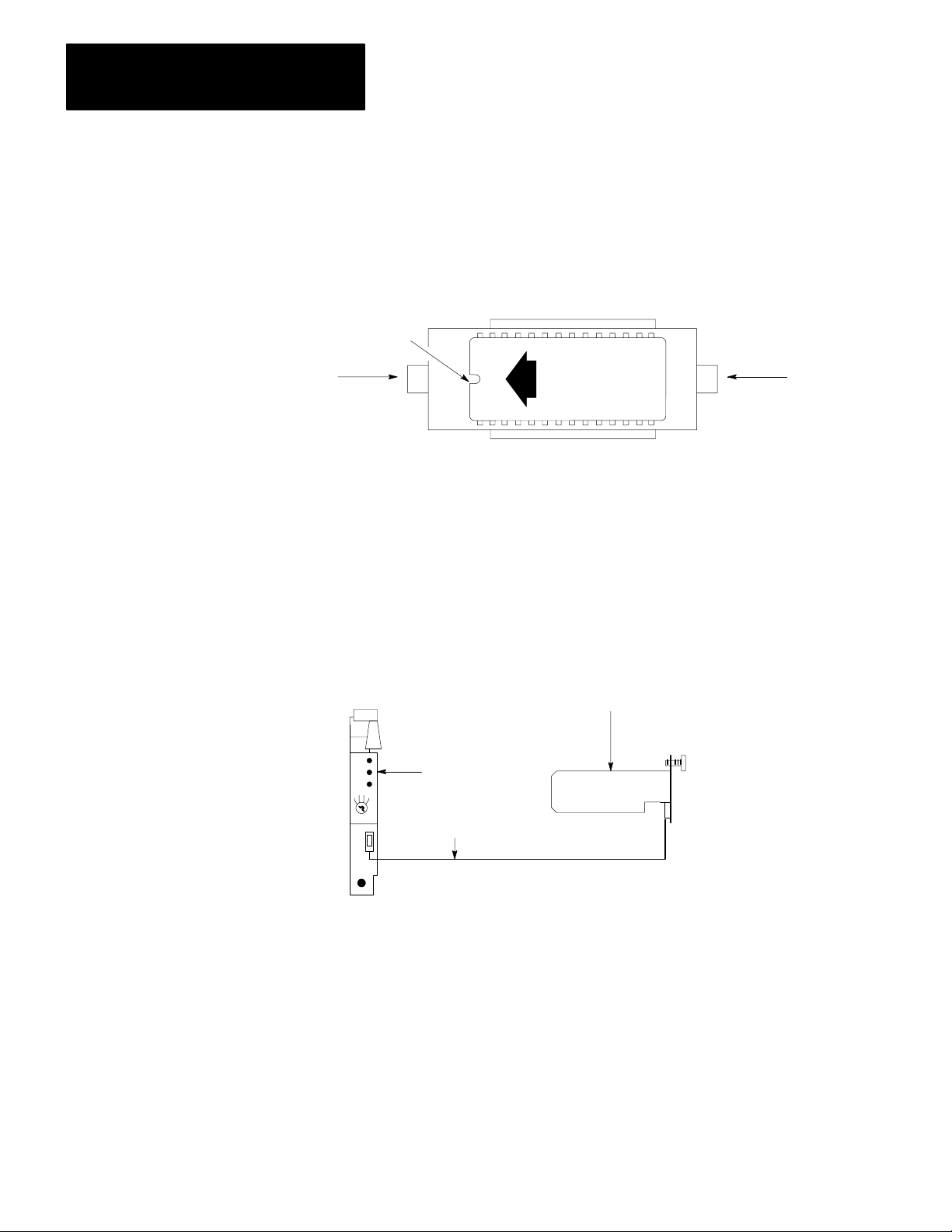
The position of the notch on the AF3 PROM, when installed, must correspond
to the position of the notch shown on the label (Figure 2.2).
Figure 2.2
AF3
Installed
PROM Installation
PROM
Notch
Lock
OFF
UP
1772AF3
DO NOT
ERASE
ON
Release
11590
To install the AF3 PROM, perform the following steps:
1. Turn the mode select switch to PROG position.
2. To maintain processor memory contents, connect an external battery pack
(Figure 2.3) to the processor with the Mini-Processor Transport Cable (cat.
no. 1772-CD).
Figure 2.3
External
Battery Backup
MiniPLC2/15 Processor
(Cat. No. 1772LV)
MiniProcessor
Transport Cable
(Cat. No. 1772CD)
Battery Pack
(Cat. No. 1771BB)
11182
3. Remove AC power from the I/O chassis.
22
4. Remove the processor module from the I/O chassis.
5. Check all AF3 PROM pins to ensure they are not bent or contaminated.
Page 8

Chapter 2
Installation/Removal Precautions
6. Loosen the screw and lift the PROM door (Figure 2.1).
7. Push the ON tab toward the center to unlock the 28-pin ZIF socket.
8. Remove the PROM if there is one in the socket.
9. Position the AF3 PROM so its notch and arrow face the OFF tab as shown
in figure 2.2.
10.Carefully align all pins with their respective sockets. Gently seat the AF3
PROM by pushing it down into its socket. Misaligned pins can bend and
miss their sockets.
11. Lock the AF3 PROM in place by pushing the OFF tab toward the center.
12.Close the PROM door and tighten the screw.
13.Install the processor module into the I/O chassis.
Removal
14.Connect AC power to the I/O chassis power supply.
15.Disconnect the external battery pack (Figure 2.3) from the processor along
with the mini-processor transport cable.
16.This completes the installation of the AF3 PROM into the Mini-PLC-2/15
controller.
To remove the AF3 PROM, perform steps 1 thru 8 of how to install the AF3
PROM. Then perform steps 12 thru 16.
23
Page 9

File Search Instruction
Chapter
3
General
The auxiliary file search instruction is an output instruction. It searches a file
looking for a match of data contained in any file word with data of a specified
match word. The instruction starts at the beginning of the file and searches
from lowest to highest word address (lowest to highest position number) and
from lowest to highest bit number. When the instruction finds a match, it
simultaneously stores the position of the file word (3-digit BCD number) and
sets the true bit. The true bit signals that the instruction found a match. Your
program logic can detect the setting of the true bit and perform the application
logic associated with the match.
Your program must cycle the instruction’s enable bit through a false-to-true
transition for each match of file data, until the instruction sets its done bit. The
instruction sets a done bit after it finds the last match in the file or if it finds no
match in the file. In the next false-to-true transition of the enable bit,
instruction clears the stored position number, and resets the instruction’s control
bits. If your program has cycled the enable bit, the instruction will immediately
begin the search again from the beginning of the file.
Generally, a minimum of two scans is required to detect each match. In the first
scan the instruction is enabled, it finds the match, stores the position number of
the matched word, and sets the true bit. In the next scan, the instruction resets
the true bit, and your program can reset the enable bit. Later in this chapter we
will describe a program that detects a match on each scan.
Programming the File Search
Instruction
You enter the file search instruction into program logic by pressing the key
sequence [SHIFT][EAF] 21 on the industrial terminal keyboard (series B or
later), or [SHIFT][SCT] 21 on the keyboard of an earlier model that does not
contain the [EAF] key. The instruction will appear as shown in Figure 3.1.
Enter the data address and result address into the instruction block as octal
(BCD) numbers from 0020 thru 3577. Typically, choose addresses from middle
to upper sections of the data table. A data address of 0400 and result address of
0406 are typical (Figure 3.2).
31
Page 10
Chapter 3
File Search Instruction
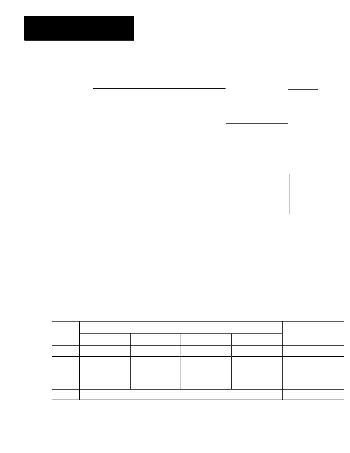
Figure 3.1
Auxiliary
Numbers shown are default values and must be replaced
by your values. The number of default address digits
originally displayed, 3 or 4, depends on the size of the
data table.
Function Format
Figure 3.2
Example File Search Instruction
Execute Aux
Function
Funtion Number:
Data Addr:
Rresult Addr:
Execute Aux
Function
Funtion Number:
Data Addr:
Rresult Addr:
01
010
010
21
0400
0405
Next, you will learn how to load data into addresses of the instruction.
You can load values into their respective addresses using the data monitor bit
manipulation mode of the industrial terminal. Press the key sequence
[SEARCH] [5] [3] followed by the word address. The industrial terminal will
display the 16 bits of the word address you entered. Then you enter the binary
equivalent of the values, one bit at a time (Figure 3.3).
Figure 3.3
Example
Word Bit Location
Location 17 16 15 14 13 12 11 10 07 06 05 04 03 02 01 00 Description
0400 Nor used 0 0 0 0 0 0 0 1 0 0 0 0 File Length = 10 words
0401 Available for 0 1 0 0 0 0 0 1 0 0 0 0 Address of File, lower 3 digits,
0402 Bit Storage 0 0 0 0 0 0 0 0 0 0 0 0 Address of File, upper 3
0403 Application Dependent Data of match word
of UserEntered Data (Binary)
410
digits, 000
32
Page 11

Chapter 3
File Search Instruction
You can also load these values in BCD. You can load BCD values into an
instruction by means of a file-to-file move instruction. Enter a file-to-file move
instruction below the file search instruction. Open the rung by inserting a
branch end instruction. Open the rung by inserting a branch end instruction at
the beginning of the rung (Figure 3.4). Make the file A address of the file-to-file
move instruction the same as data address of the file search instruction. Press
the key sequence [DISPLAY] 1. Then load data into the word identified by the
cursor. When you load data into file A of the file-to-file move instruction, the
data is automatically loaded into the file search instruction. The open branch
allows you to load data, but prevents operation of the file-to-file move
instruction when you switch the processor to run mode.
Figure 3.4
Rung for Loading AF3 PROM Instruction
Execute Aux
Function
Function Number:
Data Addr:
Result Addr:
21
0400
0405
030
EN
17
030
DN
15
Branch
End
FileToFile Move
Counter Addr:
Position:
File Length:
File A:
File R;
Rate Per Scan
030
001
004
0400-0403
0500-0503
004
You must load data into four addresses of the file search instruction starting
with the data address.
Data Address - The data address is the first address that you entered into the
instruction block. The data address is the first of four consecutive addresses
into which you load the following data (figure 3.5).
First address - Length of the instruction file to be searched, three digits,
000-999
Second address - Address of the instruction file to be searched, lower three
digits
Third address - Address of the instruction file to be searched, upper three
digits
Fourth address - Data of the match word
Match Word - your match word is your reference word. It can be a fixed value
that you enter before running your program. Or, it can be a variable that your
program enters into that address according to your application (Figure 3.5).
33
Page 12

Chapter 3
File Search Instruction
Word Bit Location
Location 17 16 15 14 13 12 11 10 07 06 05 04 03 02 01 00 Description
0400 Not used 0 1 0 File Length = 10
0401 Available for 4 1 0 File Address, lower 3 digits
0402 Bit Storage 0 0 0 File Address, upper 3 digits
0403 Application Dependent Match word data
Figure 3.5
Example of UserEntered Data (BCD)
Instruction File Address ad Length - You can assign the file to any usable
storage location in the data table. You may want to locate the file in the middle
to upper sections of the data table (addresses 0410-0421 in Figure 3.6). Choose
a file length in accordance with your programming requirements.
Result Address - The result address is the second address that you entered into
the instruction block. It is the location of the result word (Figure 3.6). The
result word is the location where the instruction momentarily stores the position
number of the file word that matches the match word (003 in this example).
Each time the instruction finds a match, it writes the BCD bit pattern of the new
position number over the old position number in the result word. The
instruction clears the result word after setting the done bit and after the next
false-to-true transition of the enable bit.
Figure 3.6
Example Locations, Instruction File & Result W
Word Bit Location
Location 17 16 15 14 13 12 11 10 07 06 05 04 03 02 01 00 Description
0405 0 0 3 Result Word
0410 FIrst word of Instruction File
0411
0412 Word Containing First Match (Position 003) Instruction File
ord
>
(10 Words)
34
.
.
.
.
0421 Last Word of Instruction File
Page 13

Chapter 3
File Search Instruction
The result word also stores control bits of the instruction in addition to the
position number. The control bits are stored in bits 17 thru 14. The 3-digit
position number is stored as a BCD bit pattern in bits 13 thru 00 (Figure 3.7).
Figure 3.7
Example Result W
Word Bit Location
Location 17 16 15 14 13 12 11 10 07 06 05 04 03 02 01 00
0405 EN LS DN TR 0 0 0 0 0 0 0 0 0 0 1 1
ord
Control
Bits
Position Number
(003 BCD in this example)
NOTE: The result word must be initialized to zero before you enable the file
search instruction for the first time. If you want to change file data or the match
word for a new search, you should do so after the instruction sets the done bit.
WARNING: Do not manipulate data in the following addresses or
bits:
Data address or result address of the instruction
Control bit 17-14 of the result word
Inadvertent changes to the above could cause the instruction to miss a match,
or detect a match when one did not exist. If this instruction directly or
indirectly controls an output, an inadvertent change to the values could
result in unpredictable operation, with possible damage to equipment and/or
injury to personnel. It could also cause a run-time error.
Enabling the Instruction
You enable the file search instruction in program logic using a separate rung
that precedes the instruction (Figure 3.8). Address an output or latched output
instruction to bit 17 of the file search instruction’s result address, 0405/17.
Program the rung’s input conditions to cycle a false-to-true transition of the
output instruction. This initiates a search for the next matching word in the file
in accordance with your application.
35
Page 14

Chapter 3
File Search Instruction
Figure 3.8
Example Minimum Logic
Function of Control Bits
010
00
Execute Aux
Function
Funtion Number:
Data Addr:
Rresult Addr:
0405
17
21
0400
0405
Control bits of the file search instruction are located in the result word, bits 17
thru 14 as follows.
Bit: 17
Function: Enable (EN)
Description: Your program logic must cause a false-to-true transition of the
enable bit for the instruction to operate. Program logic must reset then set the
enable bit before the instruction can search the file for the next match. This is
the only bit that your program logic can manipulate.
36
Bit: 16
Function: Last State (LS)
Description: The instruction toggles this bit from off to on to off each time the
instruction is enabled and then reset after each match. The last state bit is used
by the instruction to remember the status of the enable bit in the previous scan,
and to prevent the instruction from executing the next search until the enable bit
undergoes another false-to-true transition.
Bit: 14
Function: True (TR)
Description: The instruction sets this bit in the same scan that it finds a match
between data in the match word and data in a file word. The instruction resets
this bit in the next scan. You can consider its operation a one-shot. Your
program logic should detect the setting of this bit as a condition for initiating
the logic associated with a match of data.
Page 15

Chapter 3
File Search Instruction
Bit: 15
Function: Done (DN)
Description: The instruction sets this bit in the same scan that it detects the last
match in the file. The done bit remains set until the next false-to-true transition
of the enable bit. Then, the instruction resets bits 16 thru 00 of the result word
(last state, done, and true bits and the position umber in bits 13 thru 00) and
starts the search at the top of the file. The enable bit, bit 17 of this word, is
controlled by program logic.
Instruction Execution Time
Response To Errors in
UserEntered Data
The search of a file containing several consecutive match words takes less time
than a file search containing no match words. The scan of a 100 word file with
no match words takes approximately 5.5ms.
If you should enter an erroneous address, erroneous data, or erroneous function
number when entering the instruction into your program logic, the processor
will indicate a run-time error when switched from program mode to run or
run/program mode. You will have to correct the error before the processor can
execute your program.
Address Error - An address error occurs when you assign addresses that
extend into illegal areas of memory. These areas include processor word spaces
from addresses 0000-0007 and 0100-0107, and into the user program which is
dependent upon the size of the data table. The industrial terminal will display
the prompt ILLEGAL ADDRESS and the processor will not execute your
program.
Data Error - A data error occurs when you set the file length to zero, or if your
program inadvertently changes the position number in the result word to a value
greater than the file length. The industrial terminal will display the prompt
ILLEGAL DATA and the processor will not execute your program.
Example Programs
Function Number Error - A function number error occurs when you enter a
function number not associated with the auxiliary function PROM being used.
The industrial terminal will display the prompt ILLEGAL OPCODE and the
processor will not execute your program.
The following examples of program logic should help you to design your own
logic for using the file search instruction.
Search Each Scan - You can program the file search instruction to search for a
match every scan by programming two instructions as shown in Figure 3.9.
37
Page 16

Chapter 3
File Search Instruction
If the logic conditions of rung 1 are true, the enable bit, 0405/17, will latch on.
Rung 2 will execute the file search instruction. Rung 3 will unlatch the enable
bit because its logic conditions are identical to those of rung 1. The file search
instruction in rung 4 will see the enable bit reset and will likewise reset the last
state bit. Then execution can continue in the next scan. Both file search
instructions must be identical.
Figure 3.9
Example Logic for Search Every Scan
010
00
010
00
011
00
011
00
Execute Aux
Function
Funtion Number:
Data Addr:
Rresult Addr:
Execute Aux
Function
Funtion Number:
Data Addr:
Rresult Addr:
0400
0405
0400
0405
Example Program to Demonstrate the File Search Instruction
0405
L
17
21
0405
U
OFF 17
21
38
You can watch the results of the file search instruction by observing the change
in position number each time the instruction finds a match. The program
repeatedly counts in 1.5 second intervals from 000 thru 999.
Enter the program in Figure 3.10 into processor memory. Clear the memory
before entering the program using [CLEAR MEMORY] 99. Enlarge the data
table to accommodate the size of your files (nine 128-word data table sections
in this example). Enter [SEARCH] [5] [0] followed by the number of data table
sections.
Enter data into the addresses as shown in Figure 3.11 using [SEARCH] 53.
With a match word of zero and the instruction file containing all zeros, the
program stops and finds a match at each word.
Page 17

Chapter 3
File Search Instruction
030
15
030
15
0040
G
000
Figure 3.10
Example
File Search Logic
Execute Aux
Function
Funtion Number:
Data Addr:
Rresult Addr:
0030
RTO
0.1
PR 015
AC 000
040
17
0030
RTR
PR 015
AC 000
21
0031
0040
0041
PUT
000
Figure 3.11
Example Data Entry
Word Bit Location
Location 17 16 15 14 13 12 11 10 07 06 05 04 03 02 01 00 Hex Equivalent
0031
0032
0033
0034
0040
0041
where values are astored as follows:
0031 file length of 999
0032 address of instrucction file, lower 3 digits (131)
0033 address of instruction file, upper 3 digits (000)
0034 match word data
0040 zero at start up
0131 instruction file words all containing zeros
.
.
.
0 0 0 0
0 0 0 0
0 0 0 0
0 0 0 0
0 0 0 0
0 0 0 0
.
.
.
.
.
.
1 0 0 1
0 0 0 1
0 0 0 0
0 0 0 0
0 0 0 0
0 0 0 0
.
.
.
1 0 0 1
0 0 1 1
0 0 0 0
0 0 0 0
0 0 0 0
0 0 0 0
.
.
.
1 0 0 1
0 0 0 1
0 0 0 0
0 0 0 0
0 0 0 0
0 0 0 0
.
.
.
999
131
000
0000
0000
0000
39
Page 18

Chapter
File Diagnostic Instruction
4
General
The auxiliary file diagnostic instruction is an output instruction. It compares
data in a file of actual values with another file of user-entered reference values,
word-by-word and bit-by-bit. The instruction starts at the beginning of the files
and searches from lowest to highest word address and from lowest to highest bit
number. When the instruction finds a mismatch, it stops at the word containing
the mismatch and sets a bit. The instruction sets the true bit (described later) to
signal that a new mismatch was found. Then, in the same scan, it temporarily
stores the following information:
Word address and bit number found mismatched in the file of actual values
Number of mismatched values found to that point in the file
Status of the bit in the file of actual values that did not match the reference
bit
The instruction stores the above information in a 3-word result file. Your
program logic can detect the setting of the true bit, and perform the application
logic associated with the mismatch. On the next execution of the instruction,
the comparison search continues from the word/bit address where the previous
mismatch was found.
Your program must cycle the instruction’s enable bit through a false-to-true
transition for each mismatch of file data, until the instruction sets its done bit.
The instruction sets a done bit after it finds the last mismatch in the file, or if it
finds no mismatch in the file. In the next false-to-true transition of the enable
bit, the instruction clears its stored data and resets its control bits. If your
program has cycled the enable bit, the instruction will immediately begin the
search again from the beginning of the files.
Generally, a minimum of two scans is required to detect each mismatch. In the
first scan that the instruction is enabled, it finds the mismatch, stores the
information, and sets the true bit. In the next scan, the instruction resets the true
bit, and your program can reset the enable bit. Later in this chapter we will
describe a program that detects a mismatch on each scan.
41
Page 19

Chapter 4
File Diagnostic Instruction
Programming the File
Diagnostic Instruction
You enter the file search instruction in program logic by pressing the key
sequence [SHIFT] [EAF] 20 on the industrial terminal keyboard (series B or
later), or [SHIFT] [SCT] 20 on the keyboard of an earlier model that does not
contain the [EAF] key. The instruction will appear as shown in Figure 4.1.
Figure 4.1
Auxiliary
Numbers shown are default values and must be replaced
by your values. The number of default address digits
originally displayed, 3 or 4, depends on the size of the
data table.
Function Format
Execute Aux
Function
Function Number:
Data Addr:
Result Addr:
01
010
010
Enter the data address and result address into the instruction block as 4-digit
BCD numbers from 0020 thru 3577. Typically, choose these addresses from
middle to upper sections of the data table. The data address is the first word of
a 5-word file. The result address is the first word of a 3-word file. A data
address of 0500 and result address of 0520 are typical (Figure 4.2).
Figure 4.2
Example
File Diagnostic Instruction
Execute Aux
Function
Function Number:
Data Addr:
Result Addr:
20
0500
0520
Next, you will learn how to load data into addresses of the instruction.
You can load values into their respective addresses using the data monitor bit
manipulation mode of the industrial terminal. Press the key sequence
[SEARCH] [5] [3] followed by the word address. The industrial terminal will
display the 16 bits of the word address you entered. Then you enter the binary
equivalent of the values, one bit at a time (Figure 4.3).
42
Page 20

Chapter 4
File Diagnostic Instruction
Word
Location
0500
0501
0502
0503
0504
Figure 4.3
Example
17 16 15 14 13 12 11 10 07 06 05 04
000 0 00 0 1 00 0 0
Not Used
Available
for bit
Storage
010 1 00 1 0 00 1 1
000 0 00 0 0 00 0 0
010 1 00 0 0 01 0 1
000 0 00 0 0 00 0 0
User Entered Data (Binary)
Bit Location
You can also load these values in BCD. You can load BCD values into an
instruction by means of a file-to-file move instruction. Enter a file-to-file move
instruction below the file diagnostic instruction. Open the rung by inserting a
branch end instruction at the beginning of the rung (Figure 4.4). Make the
address of the source file, file A, of the file-to-file move instruction the same as
the data address of the file diagnostic instruction. Press the key sequence
[DISPLAY] 1. Then load data into the word identified by the cursor. When
you load data into file A of the file-to-file move instruction, the data is
automatically loaded into the file diagnostic instruction. The open branch
allows you to load data, but prevents operation of the file-to-file move
instruction when you switch the processor to run mode.
03 02 01 00
Description
File Length = 10
words
Address of actual value
file, lower 3 digits
upper 3 digits
Address of reference
file, lower 3 digits
upper 3 digits
Figure 4.4
Example
Rung for Loading Instruction
Branch
End
Execute Aux
Function
Function Number:
Data Addr:
Result Addr:
FileToFile Move
Counter Addr:
Position:
File Length:
File A:
File R:
Rate Per Scan
0500
0520
030
001
015
0500 0516
0600 0616
015
20
030
EN
17
030
DN
15
43
Page 21

Chapter 4
File Diagnostic Instruction
Load data into the five word file associated with the data address as follows.
Data Address - The data address is the first address that you entered into the
instruction block. The data address is the first of five consecutive addresses into
which you load the following data (Figure 4.5).
First address - length of both files to be searched (they are equal), three digit,
000-999
Second address - Address of the file of actual values, lower three digits
Third address - Address of the file of actual values, upper three digits
Fourth address - Address of the file of reference values, lower three digits
Fifth address - Address of the file of reference values, upper three digits
Figure 4.5
Example
UserEntered Data (BCD)
Word
Location
0500
0501
0502
0503
0504
Bit Location
17 16 15 14 13 12 11 10 07 06 05 04
Not Used
Available for
Bit Storage
010
523
000
505
000
Data Address File and Reference File - You can assign these files to any
usable storage location in the data table. For convenience of loading data, assign
the 5-word file of the data address and your reference file to consecutive
addresses (0500-0516 in Figure 4.6) because you will load data into both files.
Load the reference file with values which represent correct operation for each
step in your sequential application.
03 02 01 00
Description
File Length = 10
(BCD)
Address of actual value
file, lower 3 digits
upper 3 digits tal
Address of reference
file, lower 3 digits
upper 3 digits
44
File of Actual Values - You can assign this file to any usable storage location in
the data table. You may want to assign this file to addresses in the I/O image
tables or to some other file into which your program moves actual or application
values (0523-0534 in Figure 4.6)
Page 22

Chapter 4
File Diagnostic Instruction
Word
Location
0505
0506
0507
•
•
•
0516
0520
0521
0522
0523
0524
0525
•
•
•
0534
Figure 4.6
Example
17 16 15 14 13 12 11 10 07 06 05 04
Map of File Locations
Bit Location
First word of Instruction File
Last Word of Reference File
First Word of Result File
Last Word of Result File
First Word of Actual Value File
First Mismatch found at 0525/02
Last word of Actual Value File
03 02 01 00
0
1
Description
Reference File
(10 words)
Result File
(3 words)
Actual Value File
(10 words)
Mismatch found
at 0525/02
Result Address - The result address is the second address that you entered into
the instruction block. It is the first word of the result file. The result file is
where the instruction momentarily stores the following information (0520-0522
in Figure 4.7):
First word - * Control bits 17-14
* Error count, 0 to 999 (BCD), bits 13-00
Second word - * Status of the bit in the file of actual values that did not
match, bit 17
* Instruction work area, bits 16-14 (Do not use these bits
for any purpose)
* Address of word containing the mismatch, upper 3
BCD digits, bits 13-00
Third word - * Address of word containing mismatch, lower 2 BCD
digits, bits 17-10
* Bit number in word containing mismatch, 2 BCD digits,
bits 07-00
45
Page 23

Chapter 4
File Diagnostic Instruction
Figure 4.7
File
Result
Word
Location
0520
0521
0522
1
2
17 16 15 14 13 12 11 10 07 06 05 04 03 02 01 00
1 1 1 1
1
work area
2
Address of Mismatch,
lower 2 digits, 25
Control bits, 17-14
Status of mismatch bit 0525/02 in file of actual values
Bit Location
Description
001EN LS DN TR
0
5
0
0
2-digit bit number
of mismatched bit, 02
5
22
Error count in
bits 13-00, 001
Address or Mismatch,
upper 3 digitd, 005
Each time the instruction finds a mismatch (at address 0515/02 in this example),
it writes the binary bit pattern of new data over old data in the result file. After
the instruction sets the done bit, it clears all data in the result file after the next
false-to-true transition of the enable bit.
NOTE: The result file must be initialized to zero before you enable the file
diagnostic instruction for the first time. If you want to change file data for a
new search, you should do so after the done bit is set.
46
WARNING: Do not manipulate data in the following addresses
or bits:
Data address or result address of the instruction
Control bits 16-14 in the first result word
Instruction work area, bits 16-14 in the second result word
Manipulating this data could cause the instruction to miss a mismatch or to
detect a mismatch when one did not exist. If this instruction directly or
indirectly controls an output, an inadvertent change to these values could result
in unpredictable operation and cause possible damage to equipment and/or
injury to personnel. It could also cause a run-time error.
Page 24

Chapter 4
File Diagnostic Instruction
Enabling the Instruction
You enable the file diagnostic instruction in program logic using a separate rung
that precedes the instruction (Figure 4.8). Address an output or latched output
instruction to bit 17 of the file diagnostic instruction’s result address, 0520/17.
Program the rung’s input conditions to cycle a false-to-true transition of the
output instruction. This initiates a search for the next mismatched word in the
file in accordance with your application.
Figure 4.8
Example
010
Minimum Logic
Execute Aux
Function
Function Number:
Data Addr:
Result Addr:
0520
17
20
0500
0520
Function of Control Bits
Control bits of the file diagnostic instruction are located in the first result word,
bits 17 thru 14 as follows.
Bit: 17
Function: Enable (EN)
Description: Your program logic must cause a false-to-true transition of the
enable bit for the instruction to operate. Program logic must reset then set the
enable bit before the instruction can search the file for the next mismatch. This
is the only bit that your program logic should manipulate.
Bit: 16
Function: Last State (LS)
Description: The instruction toggles this bit from off to on to off each time the
instruction is enabled and then reset after each match. The last state bit is used
by the instruction to remember the status of the enable bit in the previous scan.
This prevents the instruction from executing the next search until the enable bit
undergoes another false-to-true transition.
47
Page 25

Chapter 4
File Diagnostic Instruction
Bit: 14
Function: True (TR)
Description: The instruction sets this bit in the same scan that it finds a data
mismatch between a word in the file actual values and a word in the file of
reference values. The instruction resets this bit in the next scan. you can
consider it operation a one-shot. Your program logic should detect the setting
of this bit as a condition for initiating the logic associated with a mismatch of
data.
Bit: 15
Function: Done (DN)
Description: The instruction sets this bit in the same scan that it detects the last
mismatch between files. The done bit remains set until the next false-to-true
transition of the enable bit. Then, the instruction resets the result file (except for
enable bit 17) and starts the search at the beginning of both files.
Instruction Execution Time
Response To Errors in
UserEntered Data
File comparison takes less time when the instruction finds several consecutive
mismatches. Comparison of two 50 word files with no mismatches takes
approximately 5.0ms.
If you should enter an erroneous address, erroneous data, or erroneous function
number when entering the instruction into your program logic, the processor
will indicate a run-time error when switched from program mode to run or
run/program mode. You will have to correct the error before the processor can
execute your program.
Address Error - An address error occurs when you assign addresses that
extend into illegal areas of memory. These areas include processor word spaces
from addresses 0000-0007 and 0100-0107, and into the user program which is
dependent upon the size of the data table. The industrial terminal will display
the prompt ILLEGAL ADDRESS and the processor will not execute your
program.
Data Error - A data error occurs when you set the file length to zero, or if your
program inadvertently makes the result address greater than the last address in
the file of actual values. the industrial terminal will display the prompt
ILLEGAL DATA and the processor will not execute your program.
48
Function Number Error - A function number error occurs when you enter a
function number not associated with the auxiliary function PROM being used.
The industrial terminal will display the prompt ILLEGAL OPCODE an the
processor will not execute your program.
Page 26

Chapter 4
File Diagnostic Instruction
Example Programs
The following examples of program logic should help you to design your own
logic for using the file diagnostic instruction.
Search Each Scan - You can program the file diagnostic instruction to search
for a mismatch every scan by programming two instructions as follows
(Figure 4.9).
Figure 4.9
Example Logic for Search Every Scan
010
00
010
00
011
00
Execute Aux
Function
Function Number:
Data Addr:
Result Addr:
011
00
0520
L
OFF17
20
0500
0520
0520
U
OFF 17
Execute Aux
Function
Function Number:
Data Addr:
Result Addr:
20
0500
0520
If rung 1 logic conditions are true, the enable bit, 0520/17, will latch on. Rung
2 will execute the file diagnostic instruction. Rung 3 will unlatch the enable bit
because its logic conditions are identical to those of rung 1. The file diagnostic
instruction in rung 4 will see the enable bit reset and will likewise reset the last
state bit. Then execution can continue in the next scan. Both file diagnostic
instructions must be identical.
Example Program to Demonstrate the File Diagnostic Instruction
You can observe the operation of the file diagnostic instruction using the
following example. The program finds errors in all bits of words 0130 and
0132 for a total of 32 errors. You can observe the progression of the error count
(1-32) and the progression of the bit pointer (00-17) as the program repeatedly
counts in 0.1 second intervals from 000 thru 015.
Enter the program in Figure 4.10 into processor memory. Clear the memory
before entering the program by entering [CLEAR MEMORY] 99. Enlarge the
49
Page 27

Chapter 4
File Diagnostic Instruction
data table to accommodate the size of your files (two 128-word data table
sections in this example). Enter [SEARCH] [5] [0] followed by the number of
data table sections.
Enter data into the addresses as shown in Figure 4.11 using [SEARCH] [5] [3].
You can watch the results of the file diagnostic instruction by observing the data
in the Get instruction in rung 5. First Get instruction (result word one) shows
the error count. Third Get instruction (result word three) shows the mismatched
bit number.
Figure 4.10
Example
030
File Diagnostic Logic
0030
RTO
0.1
PR 015
AC 000
040
15
030
15
0040
G
000
0041
G
000
0042
G
000
Execute Aux
Function
Function Number:
Data Addr:
Result Addr:
17
0030
RTR
PR 015
AC 000
20
0031
0040
0043
PUT
000
410
Page 28

Figure 4.11
Example Data Entry
Chapter 4
File Diagnostic Instruction
Bit Number
Address
0031
0032
0033
0034
0035
0040
0041
0042
0137
0140
0141
0142
0131
0132
0133
0134
Where the storage words hold the following values:
17 16 15 14 13 12 11 10 07 06 05 04
0000
0
0
0
0
0
0
0
0
0
0
0
0
1
0
1
0
0031 file length value of 004
0032
0033
0034
0035
0040
0041
0042
address, file of actual values, lower 3 digits (131 octal)
address, file of actual values, upper 3 digits (000)
address of reference file, lower 3 digits (137 octal)
address of reference file, upper 3 digits (000)
first result word, 0000 (hex)
second result word, 0000
third result word, 0000
0
0
0
0
0
0
0
0
0
0
0
0
0
0
0
0
0
0
0
0
0
1
1
0
0
1
1
0
0
0000 0000 0100
0
0
0
0
0
0
0
0
0
0
0
0
0
0
0
0
0
0
0
0
0
0
1
1
0
0
1
1
0
0
1
0
1
0
0
0
0
0
0
0
0
1
0
1
0
Hex Equivalent
004
999
000
137
000
0000
0000
0000
0000
0000
0000
0000
FFFF
0000
FFFF
0000
03 02 01 00
0
0
0
0
0
0
0
0
0
0
0
0
1
0
1
0
1
0
0
0
1
0
0
0
0
0
0
0
0
0
0
0
0
0
0
0
0
1
1
0
0
1
1
0
0
0
0
1
1
0
0
0
0
0
0
0
0
0
0
0
0
0
0
0
0
1
0
1
0
1
0
0
0
0
0
0
0
0
0
0
0
0
0
0
0
0
1
1
0
0
1
1
0
0
0137
0140
0141
0142
0131
0132
0133
0134
0
1
0
0
0
0
0
0
0
0
0
0
0
0
0
0
0
0
0
1
1
0
0
1
1
0
0
first word in reference file, 0000 (hex)
second word in reference file, 0000
third word in reference file, 0000
forth word in reference file, 0000
first word in file of actual values, FFFF (hex)
second word in file of actual values, 0000
third word in file of actual values, FFFF
forth word in file of actual values, 0000
0
0
0
1
1
0
0
0
0
0
0
0
0
0
0
0
0
0
0
0
0
1
1
0
0
1
1
0
0
411
Page 29

Programming Check List
Chapter
5
General
Use the following check list as an aid when entering the file search or file
diagnostic instruction into your ladder diagram program.
1. Do you have the correct function number?
2. Is your data table large enough to hold all of your files?
3. Are your address values in octal (BCD 0-7)?
4. Have you made sure that the file of actual values and the file of reference
values do not overlap (file diagnostic instruction)?
5. Have you made sure that the match word address is not an address of the
instruction file (file search instruction)?
6. Have you entered a file length greater than zero but less than or equal to
999 (BCD) in the address file?
7. If you use the [SEARCH] 53 bit monitor mode to enter data, did you
correctly position each of the bits that you set?
8. Have you enabled the instruction using correct logic (false-to-true
transition of the enable bit), and correct enable bit address (bit 17 of the
result address)?
51
Page 30

Appendix
A
AF3 Recommendations & Precautions
AF3 PROM Handling
Recommendations and
Precautions
Recommended precautions include:
Handle the AF3 PROM by the case without touching its pins.
Use a static-free work station.
Wear a conductive wrist strap that has a minimum 200k ohms resistance and
is connected to earth ground.
Ground tools prior to contacting the AF3 PROM.
Connect static-free work station to ground through a minimum 200k ohm
resistance.
Control the relative humidity of the installation area - ideal conditions are
40% to 60% relative humidity.
The following is a list of things that should not be done:
Do not handle styrofoam, plastic, or cellophane-covered articles such as
combs, cigarette packages, and candy immediately prior to handling the AF3
PROM.
Do not hand the AF3 PROM to someone who is not antistatic protected.
Do not install the AF3 PROM in areas that might contaminate or foul the
pins of the AF3 PROM.
Do not handle the AF3 PROM by its pins.
Do not slide the AF3 PROM across any surface.
Do not place the AF3 PROM in a non-conductive plastic bag.
When these precautions are followed, the potential difference between the AF3
PROM pins is reduced thereby reducing the problems associated with static
discharges.
A1
Page 31

Index
Symbols
[SEARCH] [5] [0], 38
[SEARCH] [5] [3], 32, 42, 410
C
Control bits
Done, 37, 48
Enable, 36, 47
Last state, 36, 47
True, 36, 48
D
Data address, 33, 44
E
Enabling the instruction, 35, 47
Erasing, 11
Errors, response to
Address, 37, 48
Data, 37, 48
Function number, 37, 48
Example programs, 37, 49
Execution time, 38, 48
Extended data comparison, 12
Result, 45
H
Handling precautions, A1
I
Installation, 21
Instruction file, 34
L
Loading data, 32, 43
M
Machine diagnostics, 13
Match word, 33
Mini-processor transport cables, 22
P
Programming
Check list, 51
Examples, 38, 49
R
F
File diagnostic instruction, 41
File length, 34
File of actual values, 44
File search instruction, 31
Files
Actual values, 44
Instruction, 34
Reference, 44
Reference file, 44
Removal, 23
Result address, 34, 45
Result file, 45
Result word, 34
S
Search each scan, 37, 49
Page 32

AllenBradley has been helping its customers improve productivity and quality for 90 years.
AB designs, manufactures and supports a broad range of control and automation products
worldwide. They include logic processors, power and motion control devices, manmachine
interfaces and sensors. AllenBradley is a subsidiary of Rockwell International, one of the
world's leading technology companies.
With major offices worldwide.
Algeria •
Argentina • Australia • Austria • Bahrain
Republic • Denmark • Ecuador
Indonesia • Israel
Poland • Portugal • Puerto Rico • Qatar • Romania • Russia-CIS • Saudi Arabia • Singapore
•
aiwan
• Thailand •
T
W
orld Headquarters, AllenBradley
• Italy • Jamaica •
The Netherlands
• Egypt • El Salvador • Finland • France •
Japan • Jordan • Korea • Kuwait • Lebanon
• T
, 1201 South Second Street, Milwaukee, WI 53204 USA, T
• Belgium • Brazil •
Bulgaria • Canada
Germany • Greece • Guatemala • Honduras • Hong Kong • Hungary
• Malaysia • Mexico •
urkey • United Arab Emirates • United Kingdom • United States • Uruguay
• Chile •
China, PRC • Colombia
• Costa Rica •
New Zealand • Norway
• Slovakia • Slovenia •
South Africa, Republic
• V
enezuela
el: (1) 414 3822000 Fax: (1) 414 3824444
Croatia • Cyprus
• Iceland •
• Oman • Pakistan •
• Spain •
• Yugoslavia
• Czech
India
Peru
• Philippines
Switzerland
•
•
Publication
Supersedes
17726.5.2 - March 1984
Publication 1772-827 - March 1984
Copyright
1984 AllenBradley Company
P/N
955094-46
, Inc. Printed in USA
 Loading...