

Page 1

Installation Instructions
To the Installer
Pre-installation Considerations
Fused Field Wiring Arm
Cat. No. 1771-WHF and -WHFB
This document describes:
• pre-installation considerations
• how to install the field wiring arm
• how to change a fuse on the field wiring arm
• product specifications
The fused field wiring arm provides individual output circuit protection.
It allows simple fuse replacement without removing the field wiring arm from
the I/O chassis.
Two versions are available, both of which are interchangeable with the
1771-WH field wiring arm:
• 1771-WHF - this wiring arm uses a 3 A fuse for each output. The
maximum continuous current should not exceed 2.0 A per fuse.
• 1771-WHFB - this wiring arm uses a 1.5 A fuse for each output. The
maximum continuous current should not exceed 1.1 A per fuse.
IMPORTANT
Fused field wiring arms require more clearance than
the 1771-WH field wiring arms. If you are installing
in a cabinet, make certain that your installation has
sufficient clearance for this wiring arm.
1 Publication 1771-IN072B-EN-P - December 2004
Page 2
2 Fused Field Wiring Arm Cat. No. 1771-WHF and -WHFB
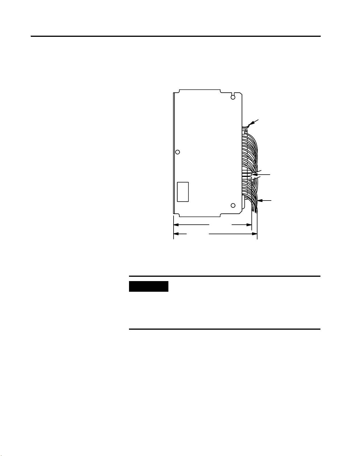
The following figure shows the minimum dimensions from the back of the
1771 I/O chassis to the front of the fused field wiring arm and to the front of
a typical wire bundle.
Back of Chassis
Top of Chassis
Fused wiring arm
Fuse holder
Installing the Fused Field Wiring Arm
195.6mm
To end of fuse holders
209.6mm
(8.25”)
(7.70”)
Maximum wire bundle
To install the fused field wiring arm:
IMPORTANT
If your application requires a single power source for
all circuits on the 16-point output module, install the
jumper supplied with the wiring arm to connect the
first 4 terminals (A, B, C and D) together. Refer to the
specific installation data for your output module for
wiring information.
1. Remove power from the wiring arm.
2. If replacing an existing wiring arm:
a. disconnect wiring from the terminals on the field wiring arm
b. release the tab securing the wiring arm to the module
c. swing the wiring arm downward and remove as shown in the
following figure
Wire bundle
Publication 1771-IN072B-EN-P - December 2004
3. Snap the 1771WHF or -WHFB wiring arm on the horizontal bar at the
bottom of the chassis as shown in the following figure.
Page 3

Fused Field Wiring Arm Cat. No. 1771-WHF and -WHFB 3
4. Swing the wiring arm upward onto the module until the arm is secured
by the tab.
5. Connect field wiring as outlined in the installation data sheet included
with your particular output module.
Horizontal bar
Changing a Fuse on the Fused Field Wiring Arm
IMPORTANT
Make certain that you allow sufficient slack in the
wiring at the bottom of the field wiring arm so that
the wiring arm can pivot sufficiently on the
horizontal bar to allow module removal.
Remove
Install
To change a fuse:
1. Remove power from the wiring arm.
Fused field wiring arm
2. Remove the fuse holder from the wiring arm as shown below:
Pivot the fuse holder
to the left and remove
from the wiring arm.
Fuse holder
3a
Insert the bottom of
the fuse holder into
the bottom contact,
press firmly.
3b
3c
Pivot the fuse holder
to the right unitl it
rests against the right
arm wall.
3. Depending on the wiring arm, replace the fuse with the following:
• 1771-WHF - 3 A fuse from Allen-Bradley Fuse Pak, cat. no. 1771-FD or
Littelfuse 2AG 3 A, part. no. 225003
• 1771-WHFB - 1.5 A fuse from Allen-Bradley Fuse Pak, cat. no.
1771-FD2 or Littelfuse 2AG 1.5 A, part no. 22501.5
Publication 1771-IN072B-EN-P - December 2004
Page 4
Specifications
4. Replace the fuse holder in the field wiring arm as shown above.
5. Reapply power to the wiring arm.
WARNING
Catalog Number 1771-WHF (3 A) and 1771-WHFB (1.5 A)
Dimensions 8.265H x 1.224W x 2.0D (inches)
Conductors
Fuses 1771-WHF - Littelfuse 2AG 3 A Part No. 225003
Optional Fuse Pak 1771-WHF - Cat. No. 1771-FD: contains 2 fuse holders and 8 2AG 3 A
Wiring Arm Screw Torque 9 pound-inches
Terminal Rating Terminals A-D rated for 8 A @ 250V
The 1771-WHF and 1771-WHFB are not suitable for use
in Class I Division 2 Groups A, B, C, D Environments.
209H x 31W x 51D (millimeters)
2
Wire Size - 14…20 AWG (2.5mm
stranded or solid, rated at 75
3/64 inch (1.22mm) insulation
Category - Refer to specific module installation instructions
1771-WHFB - Littelfuse 2AG 1.5 A Part No. 22501.5
fuse
s
1771-WHFB - Cat. No. 1771-FD2: contains 2 fuse holders and 8 2AG
1.5 A fuses
1771-WHF - Terminal 00…17 - 3.0 A, 250V per terminal with a
maximum of 12 A combined for terminals 00…17 derated linearly
from 10 °C to 2 A per terminal at 60 °C.
1771-WHFB - Terminal 00…17 - 1.5 A, 250V per terminal with a
maximum of 12 A combined for terminals 00…17.
…0.5mm2), copper only
o
C or higher,
Publication 1771-IN072B-EN-P - December 2004 4 PN 957944-28
Supersedes Publication 1771-2.11 6 - April 1992 and 1771-IN072A - January 2001 © 2004 Rockwell International Corpo ration. Printed in the U.S.A.
 Loading...