

Page 1
Data Highway or Data Highway Plus Asynchronous (RS-232-C or RS-422-A) Interface Module
Cat. No. 1770-KF2)
User Manual
Page 2
Important User Information
Because of the variety of uses for the products described in this publication,
those responsible for the application and use of this control equipment must
satisfy themselves that all necessary steps have been taken to assure that each
application and use meets all performance and safety requirements, including
any applicable laws, regulations, codes and standards.
The illustrations, charts, sample programs and layout examples shown in this
guide are intended solely for purposes of example. Since there are many
variables and requirements associated with any particular installation, the
Allen-Bradley Company, Inc. does not assume responsibility or liability (to
include intellectual property liability) for actual use based upon the examples
shown in this publication.
Allen-Bradley Publication SGI-1.1, “Safety Guidelines for the Application,
Installation and Maintenance of Solid State Control” (available from your local
Allen-Bradley office) describes some important differences between solid-state
equipment and electromechanical devices which should be taken into
consideration when applying products such as those described in this
publication.
Reproduction of the contents of this copyrighted manual, in whole or in part,
without written permission of the Allen-Bradley Company Inc. is prohibited.
Throughout this manual we use notes to make you aware of safety
considerations:
ATTENTION: Identifies information about practices or
circumstances that can lead to personal injury or death, property
damage or economic loss.
Attentions help you:
identify a hazard
avoid the hazard
recognize the consequences
Important: Identifies information that is especially important for
successful application and understanding of the product.
Interchange, ControlView, Data Highway Plus and DH+ are trademarks and PLC is a registered
trademark of Allen-Bradley Company, Inc.
HART is a registered trademark of Rosemount Inc.
IBM is a registered trademark of International Business Machines Corporation.
Page 3

Table of Contents
Introduction 11. . . . . . . . . . . . . . . . . . . . . . . . . . . . . . . . . . . .
General 11. . . . . . . . . . . . . . . . . . . . . . . . . . . . . . . . . . . . . . . . . . .
About This Manual 11
Module Description 13
Specifications 14
Data Highway Applications 15
PCL
Applications
Communication Concepts 21. . . . . . . . . . . . . . . . . . . . . . . . .
General 21. . . . . . . . . . . . . . . . . . . . . . . . . . . . . . . . . . . . . . . . . . .
Physical Link Layer 22
Software Layers 28
Installation 31. . . . . . . . . . . . . . . . . . . . . . . . . . . . . . . . . . . . .
General 31. . . . . . . . . . . . . . . . . . . . . . . . . . . . . . . . . . . . . . . . . . .
Communication
Mounting (Placing) 38
Interface Connections 39
Diagnostic Indicators 318
. . . . . . . . . . . . . . . . . . . . . . . . . . . . . . . . . . .
. . . . . . . . . . . . . . . . . . . . . . . . . . . . . . . . . .
. . . . . . . . . . . . . . . . . . . . . . . . . . . . . . . . . . . . . .
. . . . . . . . . . . . . . . . . . . . . . . . . . . . .
. . . . . . . . . . . . . . . . . . . . . . . . . . . . . . . . . .
. . . . . . . . . . . . . . . . . . . . . . . . . . . . . . . . . . . . .
Option Switches
. . . . . . . . . . . . . . . . . . . . . . . . . . . . . . . . . . .
. . . . . . . . . . . . . . . . . . . . . . . . . . . . . . . . .
. . . . . . . . . . . . . . . . . . . . . . . . . . . . . . . . .
17. . . . . . . . . . . . . . . . . . . . . . . . . . . . . . . . . . . .
31. . . . . . . . . . . . . . . . . . . . . . . . .
Asynchronous Link Protocols 41. . . . . . . . . . . . . . . . . . . . . .
General 41. . . . . . . . . . . . . . . . . . . . . . . . . . . . . . . . . . . . . . . . . . .
Definition of Link Protocol 41
FullDuplex Protocol 42
HalfDuplex Protocol 421
. . . . . . . . . . . . . . . . . . . . . . . . . . . . . .
. . . . . . . . . . . . . . . . . . . . . . . . . . . . . . . . . .
. . . . . . . . . . . . . . . . . . . . . . . . . . . . . . . . .
Message Packet Formats 51. . . . . . . . . . . . . . . . . . . . . . . . . .
General 51. . . . . . . . . . . . . . . . . . . . . . . . . . . . . . . . . . . . . . . . . . .
Application Layer 51
Network Layer 51
Message Packets 53
Message Formats 57
. . . . . . . . . . . . . . . . . . . . . . . . . . . . . . . . . . . .
. . . . . . . . . . . . . . . . . . . . . . . . . . . . . . . . . . . . . .
. . . . . . . . . . . . . . . . . . . . . . . . . . . . . . . . . . .
. . . . . . . . . . . . . . . . . . . . . . . . . . . . . . . . . . .
Data Encoding and Addressing 61. . . . . . . . . . . . . . . . . . . . .
General 61. . . . . . . . . . . . . . . . . . . . . . . . . . . . . . . . . . . . . . . . . . .
Data Encoding 61
Addressing 68
. . . . . . . . . . . . . . . . . . . . . . . . . . . . . . . . . . . . . .
. . . . . . . . . . . . . . . . . . . . . . . . . . . . . . . . . . . . . . . .
Page 4

Table of Contentsii
Error Reporting 71. . . . . . . . . . . . . . . . . . . . . . . . . . . . . . . . .
General 71. . . . . . . . . . . . . . . . . . . . . . . . . . . . . . . . . . . . . . . . . . .
ERROR WORD in User Programming
(1771KG, 1771KA, 1771KA2, 1774KA Modules) 72. . . . . . . . .
Error Codes for 1775KA 78
Internal Error Counters 719
. . . . . . . . . . . . . . . . . . . . . . . . . . . . . .
. . . . . . . . . . . . . . . . . . . . . . . . . . . . . . . .
Switch Settings A1. . . . . . . . . . . . . . . . . . . . . . . . . . . . . . . . .
General A1. . . . . . . . . . . . . . . . . . . . . . . . . . . . . . . . . . . . . . . . . . .
Message Formats B1. . . . . . . . . . . . . . . . . . . . . . . . . . . . . . .
General Asynchronous Link Error Codes (STS, EXT STS) C1.
Where to Find Asynchronous Link Error Codes C1. . . . . . . . . . . . . . .
The STS Byte C1
The EXT STS Byte C3
. . . . . . . . . . . . . . . . . . . . . . . . . . . . . . . . . . . . . .
. . . . . . . . . . . . . . . . . . . . . . . . . . . . . . . . . . .
Detailed Flowcharts D1. . . . . . . . . . . . . . . . . . . . . . . . . . . . . .
General D1. . . . . . . . . . . . . . . . . . . . . . . . . . . . . . . . . . . . . . . . . . .
Data Link Layer E1. . . . . . . . . . . . . . . . . . . . . . . . . . . . . . . . .
Data Link Layer Operation on Data Highway E1. . . . . . . . . . . . . . . . .
Floating Master E1
Message Transmission E3
Polling E3
. . . . . . . . . . . . . . . . . . . . . . . . . . . . . . . . . . . . . . . . . . . .
Data Security E4
Link Disconnect E5
. . . . . . . . . . . . . . . . . . . . . . . . . . . . . . . . . . . . .
. . . . . . . . . . . . . . . . . . . . . . . . . . . . . . . .
. . . . . . . . . . . . . . . . . . . . . . . . . . . . . . . . . . . . . . .
. . . . . . . . . . . . . . . . . . . . . . . . . . . . . . . . . . . . .
Page 5

Introduction
Chapter
1
General
A 1770-KF2 Series B module is a communication interface that links
intelligent RS-232-C or RS-422-A (asynchronous) devices to an
Allen-Bradley local area network. By setting switches on the KF2, and
changing cables, you can direct communications over a Data Highway or
a Peer Communication Link (PCL). With a 1770-KF2 module, a
computer on a PCL can communicate with any PLC-5 node on the
network. Other current Allen-Bradley products that communicate over a
PCL are the 1784-T50 Industrial Terminal System and the 1785-KA
Communication Adapter Module.
The KF2 is designed to operate in a control-room environment on a
tabletop. It takes its power from an AC wall outlet, and it gives you a
choice of full-duplex or half-duplex protocol on its asynchronous link.
The module has Data Highway compatibility, and it supports all PCL
facilities except internetworking.
(Internetworking would indicate that a computer on a PCL could talk to a
node on another PCL, or to a station on a Data Highway link. That may
be possible in the future, but it isn’t right now. A computer on a Data
Highway, though, using a 1770-KF2 and a 1785-KA can communicate
with PLC-5s on a PCL.)
About This Manual
This manual describes installation, operation, and communication
protocols of a 1770-KF2 module; and it assumes that you are already
thoroughly familiar with how to program your computer or other
intelligent asynchronous device. It does not assume prior knowledge of
the Allen-Bradley Data Highway or a Peer Communication Link.
Table 1.A lists related documentation that might be helpful in conjunction
with this manual. For more details about the programming and operation
of specific Allen-Bradley programmable controllers, refer to the
appropriate user’s manual for that controller.
1-1
Page 6

Chapter 1
Introduction
T
able 1.A
Related
Documentation
Publication
Number
1770-6.2.1 1770-810
1771-6.5.1 1771-801
1771-6.5.15 1771-822
1771-6.5.8 1771-811
1775-6.5.1 1775-802
1773-6.5.2 1773-801
1785-6.8.1
1785-6.6.1
6226-6.5.1
Old Publication
Number
Title
Data Highway Cable Assembly and Installation
Manual
Communication Adapter Module
(Cat. No. 1771-KA2) User’s Manual
Communication Controller Module
(Cat. Nos. 1771-KE, -KF) User’s Manual
PLC-2 Family/RS-232-C Interface Module
(Cat. No. 1771-KG) User’s Manual
PLC-3 Communication Adapter Module
(Cat. No. 1775-KA) User’s Manual
PLC-4 Communication Interface Module
(Cat. No. 1773-KA) User
PLC-5/15 Processor Manual
PLC-5/15 Assembly & Installation Manual
Industrial Terminal Support Software System
Manual
’
s Guide
1784-6.5.1
1785-6.5.1
Industrial T
PCL-to-Data Highway Communication Adapter
Module (1785-KA) User’s Manual
erminal (1784-T50) User’s Manual
This manual is organized as follows:
Chapter 2 — Explains basic communication concepts.
Chapter 3 — Tells how to install a KF2 module.
Chapters 4, 5, and 6 — Describe the communication protocol used by
a KF2 module.
Chapter 7 — Summarizes error reporting.
1-2
Page 7

Chapter 1
Introduction
Module Description
Figure 1.1 shows the 1770-KF2 module’s hardware features:
Diagnostic Indicators
Connectors for Data Highway and RS-232-C Devices
Communication Option Switches
On/Off Switch, Power Plug, Fuse, and Voltage Select Switch
Figure 1.1
1770-KF2
Communication Interface Module
ALLEN–BRADLEY
DATA HIGHWAY
COMMUNICATION INTERFACE
XMTG RCVG RDY ACTV CPUPWR
A KF2 also features extensive self-diagnostics. At power-up, tests are run
on internal memory, timers, and firmware integrity. Any failure causes
the red front-panel CPU indicator to flash. Also, the module continuously
checks the memory and firmware during operation.
1-3
Page 8

Chapter 1
Introduction
Specifications
Table 1.B lists KF2 module specifications.
T
able 1.B
KF2
Module Specifications
Specification Requirements
Communication Rates
Functions
Location
Communication Ports
•
Data Highway: 57,600 bits per second (recommended)
•
Peer Communication Link: 57,600 bits per second
(recommended)
•
Asynchronous: Switch selectable from 1
per second
•
Interface a programmable RS-232-C or RS-422-A
compatible device with an Allen-Bradley Data Highway
•
Serve as a replacement for a 1771-KD Communication
Controller Module.
• T
abletop (or other horizontal surface)
•
Controlled environment, e.g., of
•
Data Highway: 15-pin male EIA D-connector
•
Peer Communication Link: 15-pin male EIA
D-connector
•
Data Highway Monitor: 9-pin female EIA D-connector
•
Asynchronous (RS-232-C/RS-422-A): 25-pin male
EIA D-connector
10 to 9.600 bits
.
fice or control room
Cabling
Power Requirements
Ambient T
Rating
Ambient Humidity Rating
Physical
emperature
•
Data Highway: Data Highway Dropline Cable
(Cat. No. 1770-CD)
•
Asynchronous RS-232-C: User-Supplied Data
T
erminal Interface Cable or Modem Interface Cable
•
Asynchronous RS-422-A: User-Supplied Data T
Interface Cable
•
Selectable: 115 V/60 Hz or 230 V/50 Hz
• W
atts: 3.5
• 32oF to 1
• -40oF to 185oF (-40oC to 85oC) Storage
•
10% to 80% Non-Condensing
•
Size: 10-3/8 in. x 10.0 in. x 3-3/8 in. (263.5 mm x
254 mm x 85.7 mm)
• W
13oF (0oC to 45oC) Operational
eight: 6.0 pounds (2.7 Kg)
erminal
1-4
Page 9
Chapter 1
Introduction
Data Highway Applications
A KF2 module provides either a point-to-point link or a multi-drop link
between an Allen-Bradley Data Highway and an intelligent asynchronous
device. By “intelligent asynchronous device” we mean any device that
complies with RS-232-C or RS-422-A electrical standards and that can be
programmed to handle the communication protocol described in
Chapters 4 through 6 of this manual. Throughout this manual, we will
also use the term “computer” in a general sense to refer to this type of
device. Some examples include:
An Allen-Bradley Advisor 2+TM Color Graphic System
A PLC-3 Programmable Controller and Connected Communication
Adapter Module (Cat. No. 1775-KA)
A PLC-2 Family Programmable Controller and Connected PLC-2
Family/RS-232-C Interface Module (Cat. No. 1771-KG)
A PLC-4 Microtrol Programmable Controller and Connected
Communication Interface Module (Cat. No. 1773-KA)
A Variety of Minicomputers and Microcomputers
In point-to-point configuration, the KF2 module connects one intelligent
asynchronous device as a single station on a Data Highway. Figure 1.2
illustrates this configuration. Point-to-point links can use either peer-topeer (full-duplex) or master-slave (half-duplex) communication.
Figure 1.2
Point-to-Point
Links
Computer
Modem
Modem Link
Modem
KF2 Module KF2 Module
Allen–Bradley Longline
RS-232-C Link
(7,000 Cable-Ft. Max.)
Asynchronous Link
(50 Cable-Ft. Max.)
KF2 Module
Data Highway Link
1771-KG
Module
PLC-2/30
Processor
Computer
11687
1-5
Page 10
Chapter 1
Introduction
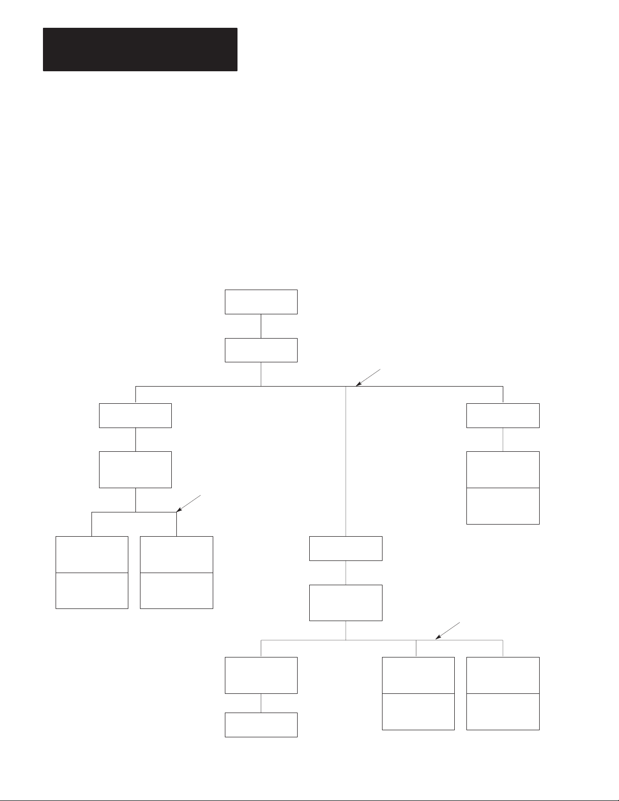
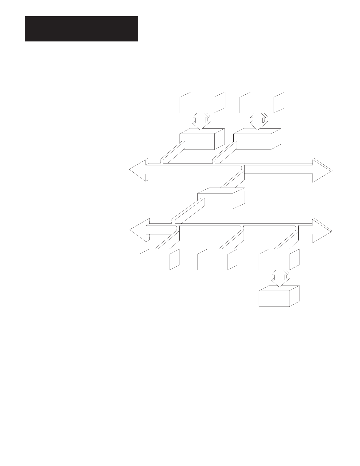
In a multi-drop configuration, one intelligent asynchronous device
connects to several Data Highways through sets of modems and KF2
modules. Figure 1.3 illustrates this type of configuration. If the
multi-drop link consists of broadband modems, you can select either
peer-to-peer (full-duplex) or master-slave (half-duplex) communication.
If the multi-drop link consists of baseband modems, you must use
master-slave (half-duplex) communication because baseband modems
support only one communication channel.
Figure 1.3
Multi-Drop
Link
Computer
1775-KA
Module
PLC-3
Processor
Modem
KF2 Module
1773-KA
Module
PLC-4
Microtrol
Processor
Modem
Multi-Drop Modem Link
Modem
1771-KG
Module
Data Highway Link
PLC-2/15
Processor
Modem
KF2 Module
Data Highway Link
1-6
KF2 Module
Computer
1771-KA
Module
PLC-2
Processor
1774-KA
Module
PLC
Processor
11688
Page 11

Chapter 1
Introduction
In either type of configuration, there are three possible ways you can
connect a KF2 module:
Direct connection to an intelligent asynchronous device if the KF2
module is mounted within 50 cable-feet of an RS-232-C, or within
4,000 cable-feet of an RS-422-A device.
Direct connection to an Allen-Bradley 1775-KA, 1773-KA, or
1771-KG interface module if the KF2 module is within 50 cable-feet of
the other module.
Modem connection if the KF2 module is within 50 cable-feet of an
RS-232-C compatible modem, or within 4,000 cable-feet of an
RS-422-A device.
You can also use the 1770-KF2 module to replace a 1771-KD module in
an existing application. By properly setting the option switches on the
KF2 module, you can make this replacement without having to change
any application programs that you were using with the 1771-KD module.
Refer to Chapter 3 under “Replacing a 1771-KD Module with a KF2
Module” for switch settings.
PCL Applications
A 1770-KF2 Series B module provides either a point-to-point or
multi-drop link between an Allen-Bradley Peer Communication Link
(PCL) and an intelligent asynchronous device. You can use a PCL link
when you have a small number of PLC-5/15 stations in a local cluster.
Typically, a PCL link connects PLC-5/15s that need to communicate with
each other frequently. If your system requires more than ten stations,
consider breaking it into smaller PCL links connected by a Data Highway
to optimize performance.
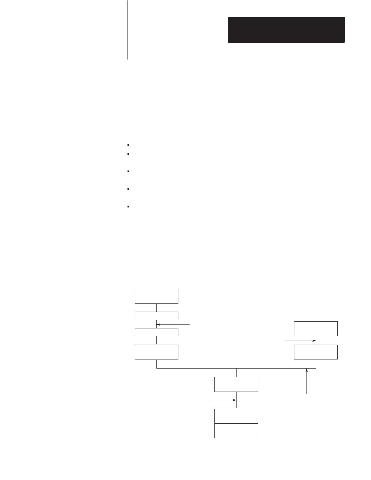
The KF2 Series B module provides an interface between either:
an RS-232-C or RS-422-A asynchronous link to Data Highway, or
an RS-232-C or RS-422-A asynchronous link to a PCL network as
shown in Figure 1.4.
1-7
Page 12
Chapter 1
Introduction
Figure 1.4
A
PCL Network Connected to a Data Highway
1770-KF2
TM
1785-KA
PLC-3
1775-KA
PCL
Advisor 2+
Data Highway
PLC-5 PLC-5 1770-KF2
1-8
Computer
14690
Important: A 1770-KF2 module on a PCL link cannot access a station
on the Data Highway through a 1785-KA module. A KF2 module on the
Data Highway, however, can access a station on a PCL link through a
1785-KA.
Page 13

Chapter
Communication Concepts
2
General
This chapter presents some of the concepts of communication with the
KF2 module. It describes the physical communication links to the module
and the various levels of software necessary to make those links work.
A KF2 module connects a computer or programmable controller to an
Allen-Bradley local area network (LAN), either Data Highway or Peer
Communication Link (PCL). In doing so, the module acts as an interface
between two physical communication links:
Data Highway or PCL, Called “Network Link”
RS-232-C or RS-422-A, Called “Asynchronous Link”
A Data Highway network provides peer-to-peer communication between
the KF2 module and other stations on the Data Highway. It uses a
half-duplex (polled) protocol and rotation of link mastership.
A Peer Communication Link provides peer-to-peer communication
between the KF2 module and other stations on the PCL. The PCL uses
token-passing to control access to the link.
The asynchronous link can provide either peer-to-peer communication
through a full-duplex (unpolled) protocol, or master-slave communication
through a half-duplex (polled) protocol.
In addition to a physical link layer, communication on either the network
link or the asynchronous link involves three levels of software:
Application Layer
Network Layer
Data Link Layer
If you are using a computer on an asynchronous link, you must program
all three layers. For A-B programmable controllers, you need program
only the application layer; the Data Highway interface modules (or for the
PCL, the PLC-5 itself) automatically take care of the other two layers.
The rest of this chapter presents some of the concepts behind the physical
communication links and their three software layers. For more details on
2-1
Page 14

Chapter 2
Communication Concepts
the application and network layers, refer to Chapters 5 and 6. For more
on the data link layer of the asynchronous link, refer to Chapter 4 and
Appendix D.
Physical Link Layer
The physical link layer is a set of cables and interface modules that work
together to provide a channel for communication between the various
points, called stations, on the physical link. A station consists of an
intelligent programmable device (e.g., PC or computer) and the module or
modules that interface it with the physical link.
In this way, the KF2 module allows stations on one link to communicate
with stations on the other link. Since these two physical links have
different communication protocols, the KF2 module serves mainly as a
protocol translator.
Data Highway
The Data Highway and the PCL are both local area networks (LANS) that
allow peer-to-peer communication among up to 64 stations. Figure 2.1
illustrates a Data Highway network.
The Data Highway link consists of a trunkline that can be up to
10,000 feet long and droplines that can be up to 100 feet each. Each
station is at the end of a dropline.
2-2
A Data Highway link implements peer-to-peer communication through a
modified token-passing scheme called the floating master. With this
arrangement, each station has equal access to become the master. The
stations bid for temporary mastership based on their need to send
information.
Unlike a master/slave relationship, a floating master relationship does not
require the current master to poll each station to grant permission to
transmit. Therefore, it provides a more efficient network because there is
less overhead per transaction.
Page 15
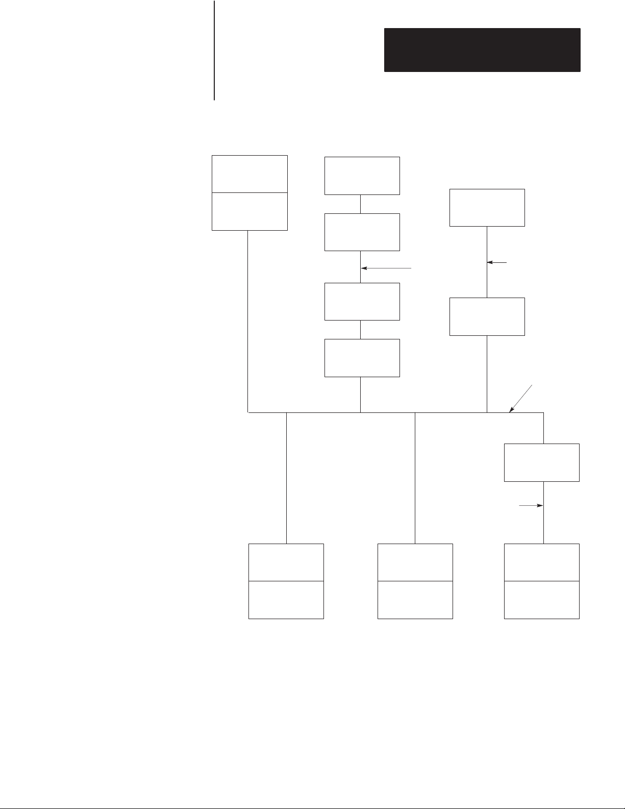
Figure 2.1
Data
Highway Network
Chapter 2
Communication Concepts
PLC-3
Processor
1775-KA
Module
Computer
MODEM
MODEM
1770-KF2
Module
MODEM
Link
Advisor 2+
1770-KF2
Module
TM
RS-232-C Link
50 Cable-Ft. Max.
Data
Highway
Link
1770-KF2
Module
RS-232-C Link
50 Cable-Ft. Max.
1771-KA
Module
PLC-2/15
Processor
1773-KA
Module
PLC-4
Loop
1771-KG
Module
PLC-2/30
Processor
Stations
A station consists of a computer or PC processor and the module or
modules that interface it with the Data Highway link. Within a station
that contains a KF2 module, an asynchronous link is required as an
auxiliary link to the network. Figure 2.1 shows three such stations.
11299A
2-3
Page 16

Chapter 2
Communication Concepts
One station consists of an Advisor 2+TM Color Graphic System connected
to a KF2 module through an RS-232-C link limited to 50 cable-feet.
Another station consists of a computer interfacing with a KF2 module
through a modem link that is limited only by the nature of the modems
themselves.
The third such station consists of a 1771-KG module interfacing a
PLC-2/30 processor with a KF2 module through an RS-232-C link limited
to 50 cable-feet. If you want a link longer than 50 cable-feet, you can use
modems.
PC Programming
All Allen-Bradley PC processors can be connected to a Data Highway
through an appropriate station interface module. All of these processors
can receive and reply to command messages, and some of them can also
transmit command messages. For an explanation of how to program PCs
to send and receive messages, refer to the user’s manual for the
appropriate station interface module.
Computer Programming
The communication protocol for the Data Highway link is transparent to a
computer on the network. However, for a computer to send or receive
messages through the Data Highway network, it must be programmed to
communicate with its KF2 module over an asynchronous link.
Chapters 4, 5, and 6 describe the protocol that you must program your
computer to use on such an asynchronous link.
Peer Communication Link
A PCL has much the same topology as the Data Highway, described in the
previous chapter; but it is designed for fewer, closely coupled, PCs. The
PCL implements peer-to-peer communication with a token-passing
scheme to rotate link mastership among the stations connected to that link.
Since such a method does not require any polling, it is very time efficient.
The PCL also uses timeouts to recover from any fault that disables the
station that has the token.
2-4
Page 17
Chapter 2
Communication Concepts
Stations
A station consists of a computer, or PC processor, and the module or
modules that interface it with the PCL. Within a station that contains a
KF2 module, an asynchronous link is required as an auxiliary link to the
network. PCL networks currently use PLC-5 processors, which interface
directly to the PCL; and no station interface module is required. You can,
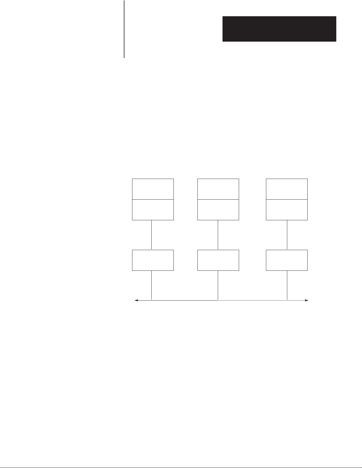
however, connect other PCs, as shown in Figure 2.2.
Figure 2.2
PCL
Network Connected to V
arious PC Processors
PLC-4
Loop
1773-KA
Module
KF2
Module
PLC-3
Processor
1775-KA
Module
KF2
Module
PLC-2/30
Processor
1771-KG
Module
KF2
Module
PCL
11300A
Other PCL stations can be computers that interface with the KF2 module
either directly or through a modem link, or a PCL-to-Data Highway
communication adapter (1785-KA), which you can use to connect a PCL
to the Data Highway.
PC Programming
All Allen-Bradley PC processors can receive command messages and
reply to them, and some can transmit commands. For an explanation of
how to program PCs to send and receive messages, refer to the user’s
manual for that particular station interface module or, in the case of a
PLC-5, the processor itself.
2-5
Page 18

Chapter 2
Communication Concepts
Computer Programming
The communication protocol for the PCL is transparent to a computer on
the network. However, for a computer to send or receive messages
through the PCL, it must be programmed to communicate with its KF2
module over an asynchronous link. Chapters 4, 5, and 6 describe the
protocol that you must program your computer to use on this link.
Configuration Selection
Figure 2.1 and Figure 2.2 illustrate configurations in which PC stations
can communicate with each other and with computers through network
ports and asynchronous ports on the station interface modules. Each
configuration is useful, depending on your application.
If you want to provide a peer-to-peer communication among many PCs
and/or a computer, use a Data Highway network as shown in Figure 2.1.
For communication among a small cluster of PCs and a computer, use a
PCL as shown in Figure 1.4. For distances longer than the networks
provide, you can use an auxiliary longline asynchronous (RS-232-C or
RS-422-A) link or a modem link.
A Data Highway link has a communication rate of 57,600 bits per second
and a half-duplex (peer-to-peer, polled) protocol. A KF2 asynchronous
link is selectable RS-232-C/RS-422-A and has a selectable
communication rate up to 9,600 bits per second. It uses a selectable
protocol of half-duplex (master-slave polled) or full-duplex (peer-to-peer,
unpolled).
A master-slave communication protocol can be selected for any link to a
computer. A peer-to-peer communication protocol can be selected only
for a point-to-point link or a broadband modem multi-drop link to a
computer.
Even with only two stations, you may want a Data Highway or a Peer
Communication Link. Either network provides the flexibility of easy
reconfiguration or expansion if you want to be able to add more stations
later, and it also provides more error checking than an asynchronous link.
2-6
Page 19

Chapter 2
Communication Concepts
Configuration Considerations
Allen-Bradley manufactures a variety of communication interface
modules for different applications:
Communication
PLC Communication Adapter Module
PLC-2 Family Communication Adapter Module
PLC-3 Communication Adapter Module
PLC-4 Communication Interface Module
PLC-5/Data Highway Communication Adapter Module
PLC-2 Family/RS-232-C Interface Module
Communication Controller Modules
Communication Interface Module
Provides interface between:
1
A PC Processor and a Data Highway Communication Link
2
A PC Processor and an RS-232-C Communication Link
3
A RS-232-C Communication Link and a Data Highway Communication Link
Interface Module
Cat. No.
1774-KA 1
1771-KA2 1
1775-KA
1773-KA
1785-KA ––
1771-KG 2
1771-KE, -KF
1770-KF2B 3
Note
1 & 2
1 & 2
3
A 1785-KA module interfaces a Data Highway with a Peer
Communication Link. The module resides in a 1771 I/O rack and
receives its power from the rack’s backplane.
A 1771-KE module must be installed in an I/O chassis. The 1771-KD,
1771-KF, and 1770-KF2 are standalone modules. Modules 1771-KE,
1771-KF, and 1770-KF2 provide either peer-to-peer or master-slave
communication between an RS-232-C link, or to a modem link, and the
Data Highway.
RS-422-A/Data Highway Interface
A 1770-KF2 provides an interface between an RS-422-A communication
link and a Data Highway communication link. The 1770-KF2 is
functionally identical to the 1771-KF except that it is a desktop module,
provides its own power supply, and supports both RS-232-C and
RS-422-A communication.
RS-232-C/RS-422-A — PCL Interface
A 1770-KF2 provides an interface between an RS-232-C or RS-422-A
asynchronous link and a Peer Communication Link network.
2-7
Page 20

Chapter 2
Communication Concepts
Software Layers
Each of the physical links just described requires three layers of software
to enable communication to take place. The layers are defined as follows:
Application Layer — Controls and executes the actual tasks, or
commands, specified in the communication between stations. To
program this layer, use the commands described in Chapter 5.
Network Management Layer — Handles queueing, sequencing,
routing, and error status reporting for communication. If your physical
link contains only Allen-Bradley PCs, you do not have to program this
layer. Otherwise, refer to Chapter 5 for a description of how to
program this layer for an asynchronous link to a computer.
Data Link Layer — Controls the flow of communication over the
physical link by establishing, maintaining, and releasing the
communication channel between stations. If your physical link
contains only Allen-Bradley PCs, you do not have to program this
layer. Otherwise, refer to Chapter 4 for a description of how to
program this layer for an asynchronous link to a computer.
Application Layer
The application layer concerns the specific commands that you can
program at a given station to cause that station to communicate over the
link. This layer is the same for both asynchronous and network links.
The types of commands that a station can transmit and receive vary with
the type of processor at that station. Chapter 5 describes the commands
that each type of PC processor can transmit or receive. To program your
computer to communicate with a PC, use the appropriate command
message format shown in Chapter 5.
Message Structures
All messages on a network have the same fundamental structure,
regardless of their function or destination. If you could freeze a block
while it is in transmission, you would see two types of message bytes:
Protocol Bytes
Data Bytes
Protocol bytes are used by the network to get the message to its
destination. Data bytes are delivered to the application at the destination.
The methods by which these bytes are filled is determined by the nature
of the station from which the transmission block originates. For example,
if a transaction originates from a PC station, the station interface module
2-8
Page 21

Chapter 2
Communication Concepts
automatically fills the protocol bytes. If the transaction originates from a
computer station, your computer software must supply the necessary
protocol. In both cases, the data bytes contain information supplied by
application programs.
Command/Reply Cycle
Any network transaction consists of two messages: a command and a
reply.
The two parts provide extra data integrity by ensuring that a required
action always returns some sort of status, whether an error code or data.
As a frame of reference, the command initiator is always referred to as a
local station, and a reply initiator is always referred to as a remote station.
Unless noted otherwise, whether in a network link or an asynchronous
link, our reference will be limited to a single local station and a single
remote station.
The network layer protocol distinguishes a command from a reply.
Obviously, the data area of a command and its corresponding reply
depend on the type of command.
Priority
Each message on a Data Highway link is classified as either high priority
or normal priority.
Each message on a PCL is classified as normal priority.
Priority levels of messages determine the order in which stations are
polled and allowed to transmit messages. In the polling process, stations
with high priority messages will always be given priority over stations
with normal priority messages.
You specify the priority level for each command in the message command
code. The station that receives a command message must establish the
same priority level for its corresponding reply message.
Important: Stations with high priority messages are given priority over
stations with normal priority messages throughout the command/reply
message cycle. For this reason, a command should be given a high
priority designation only when special handling of specific data is
2-9
Page 22

Chapter 2
Communication Concepts
required. Using an excessive number of high priority commands defeats
the purpose of this feature and could delay or inhibit the transmission of
normal priority messages.
Command Structures
There are four basis types of command on a Data Highway network or a
standalone link:
Read
Write
Diagnostic
Mode Select
Reads
There are two types of read:
Physical
Unprotected
A physical read allows you to read any area of PC memory at a remote
station. However, a PC processor cannot originate a physical read
command; only a computer can originate a physical read.
An unprotected read can access only the data table area of PC memory.
Both computers and PCs can initiate unprotected reads.
Any read can request up to 122 16-bit words of contiguous data from PC
memory.
Writes
We can classify write commands both by their application and by their
level of memory access.
2-10
As an application issue, writes are divided between bit writes and
word writes. Bit writes allow the local station to control bits in the
data table of a remote station.
Word writes allow the local station to write up to 121 contiguous words of
data into the remote station’s memory, provided you abide by the
restrictions on memory access discussed next.
Page 23

Chapter 2
Communication Concepts
As with reads, writes also are classified by the level of access to PC
memory. Non-physical writes can access only the data table at a remote
PC; physical writes can access all of user memory, including PC program
memory.
Non-physical writes can be further subdivided into protected and
unprotected. Protected writes can access only specified areas of the
remote PC’s data table memory. The accessible areas are defined by
memory protection rungs in the remote PC’s ladder diagram program.
Unprotected writes, on the other hand, can access any area of the remote
PC’s data table.
In most cases, switch settings on the remote station’s interface module can
disable the module from executing each of these types of write
commands.
Diagnostics
Diagnostic commands have to originate from a device other than a PC.
You can use these commands to return status information from a remote
or local station or to alter some on-board parameters at a station interface
module. Diagnostic commands are particularly useful during a start-up or
during on-line debugging.
Mode Select
Mode select commands allow you to load a new PC program from a
remote computer station. The operation of these commands varies by PC
processor type. These commands can be issued only by a computer.
Network Management Layer
The network management layer is concerned with the specifics of
conveying a message safely from its source to its destination. This layer
is the same for both asynchronous and network links.
If your physical link contains only Allen-Bradley PCs, you do not have to
program anything for this layer; the communication interface modules
automatically take care of it. If your physical link contains a computer,
then refer to Chapter 5 for a description of how to program this layer at
the computer station.
2-11
Page 24

Chapter 2
Communication Concepts
Generally, you need not be concerned with the interaction of station
interface modules on the network.
This means that your application programs at the PCs and computers
along the network need not involve themselves with interstation protocol,
handshaking, or control of the network link. This is all carried out
automatically by the station interface modules. However, an
understanding of station interaction is useful both to computer
programmers and PC programmers. It allows optimum use of network
commands and fault diagnostics.
Error Checking
Error codes can be generated at two places: remote station modules and
local station interface modules. For codes that are returned from a local
station module, two types of condition can exist:
Application programs use the wrong message format or issue illegal
commands.
The local station cannot complete a transaction due to network
problems.
A remote station can return only the codes associated with an application
problem at the remote station. Typically, these involve either the PC
processor being off-line (in Program mode, for example) or the command
trying to access memory areas blocked by either the interface module or
the user application program.
In the network layer protocol, command message status is returned in a
reply status byte. A value of zero in the status byte indicates successful
transmission of the corresponding command. It is up to the local
application program to display and act on the value of the returned byte.
2-12
Page 25

Installation
Chapter
3
General
Communication Option Switches
This chapter explains how to install the 1770-KF2 module. There are four
parts to installation:
Setting Communication Option Switches
Situating the Module for Operation
Connecting the Module to the Network and Asynchronous Links
Observing the Diagnostic Indicators
Please read the first three chapters of this manual carefully before
attempting any of the installation steps.
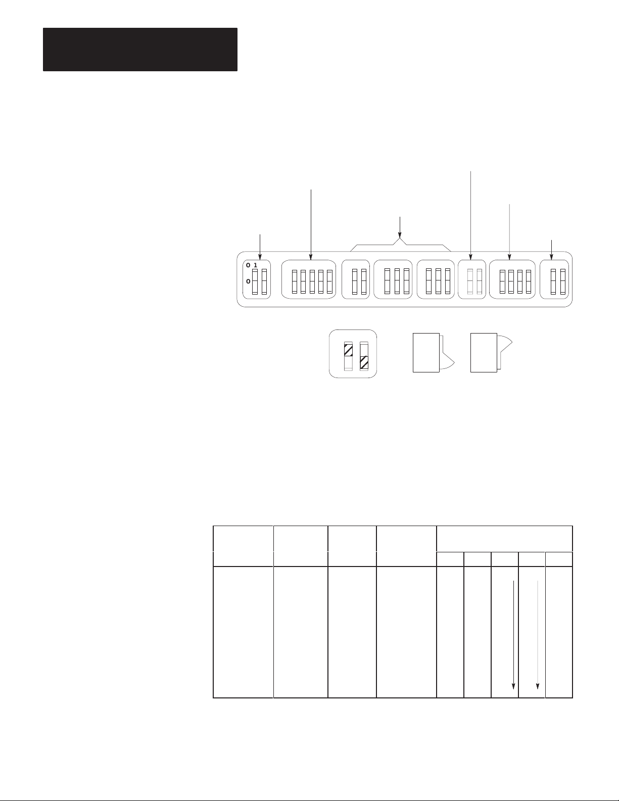
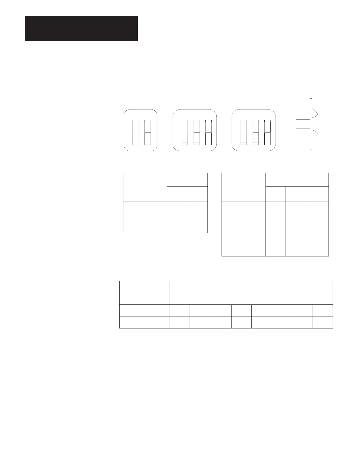
The KF2 module has 8 switch assemblies (Figure 3.1) that enable you to
select various communication options. The switch assemblies and their
corresponding options are:
Switch
Assembly
SW-1
SW
-2, SW-3, SW
SW-5
SW-6
SW-7
SW-8
-4
Communication Option
Asynchronous Link Features
Station Number
Network Link Communication Rate
Asynchronous Link Communication Rate and Diagnostic
Commands
Selecting the Network Link
RS-232-C/RS-422-A Selection
3-1
Page 26
Chapter 3
Installation
Figure 3.1
Communication
RS-232-C/RS-422-A
Selection (SW-8)
Option Switches
Asynchronous Link
Features (SW-1)
Network Link
Communication
Rate (SW-5)
Station Number
(SW-2, SW-3, SW-4)
Asynchronous Link
Communication
Rate (SW-6)
Network Link
Selection
(SW-7)
O
N
O
F
F
12
O
N
O
F
F
12
345
O
N
O
F
F
12
123
O
N
O
F
F
123
O
N
O
F
F
O
N
O
F
F
12
1234
O
N
O
F
F
O
N
O
F
F
12
Front View Side View
12
O
N
O
F
F
ON
OFF
ON
ON
OFF
OFF
13529
Important: The KF2 reads the status of the communication option
switches only at power-up, so you must make your selection with the
KF2’s power off.
Asynchronous Link Features
The following table shows you how to set the asynchronous link features
using Switch Numbers 1, 2, and 5.
If You W
Protocol as:
Full Duplex
Full Duplex
Full Duplex
Full Duplex
Half Duplex
Half Duplex
Full Duplex
Half Duplex
to Select
ant
W
ith Error
Check as: Parity as:
BCC None No OFF OFF N/A N/A OFF
BCC Even No ON OFF OFF
BCC None Yes OFF ON OFF
BCC Even Yes ON ON OFF
BCC None No OFF OFF ON
BCC Even No ON OFF ON
CRC None Yes OFF ON ON
CRC None No ON ON ON
With
With
Embedded SW-1
Responses: 1 2 3 4 5
3-2
Page 27
Chapter 3
Installation
Switch 3 determines whether the asynchronous port of the KF2 module
can detect duplicate messages transmitted to it.
If You W
Detect and Ignore Duplicate Messages
Accept All Messages Regardless of Duplication
ant Y
our Module to:
Set Switch 3:
ON
OFF
Switch 4 determines whether the module uses and recognizes the
following handshaking signals: data set ready, request to send, clear to
send, data carrier detect, and data terminal ready.
If You W
Use Handshaking Signals
Ignore Handshaking Signals
ant the Module’s Asynchronous Port to:
Set Switch 4:
ON
OFF
Important: If you select half-duplex, the KF2 uses handshaking signals
even if Switch 4 is set OFF.
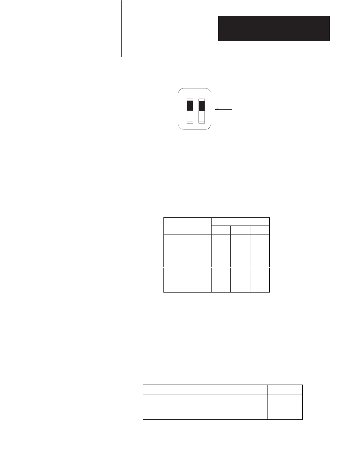
Station Number
Switch Assemblies SW-2, SW-3, and SW-4 are for setting the network
station number of the KF2 module. For the Data Highway, the station
number is a 3-digit octal number that identifies the KF2 module as a
unique station. Valid station numbers for the KF2 module in Data
Highway mode are 010 to 077 and 110 to 376 octal. For a PCL, the
station number is 2 digits; set both switches in SW-2 OFF. Valid station
numbers for the KF2 in PCL mode are 00 to 77 octal.
Figure 3.2 shows an example of how to set the KF2 station number to
037 octal. The switches in Assembly SW-2 set the first (left-most) digit
of the station number; Switch Assembly SW-3 sets the middle digit; and
Switch Assembly SW-4 sets the last (right-most) digit.
Station numbers play an important part in the polling scheme described in
Chapter 2. They can also influence the order in which mastership is
transferred between network stations. Therefore, we recommend that you
always begin numbering stations with the lowest possible number and
continue with the next available number in sequence.
3-3
Page 28
Chapter 3
Installation
Figure 3.2
Station
Number
Switch Groups
SW-2 SW-3 SW-4
12
O
N
O
F
F
First Digit Second and Third Digits
If You Want
to Set This
Digit:
0
1
2
3
12
O
N
O
F
F
Set Switches
No. 1 No. 2
OFF OFF
OFF ON
ON OFF
ON ON
3
12
O
N
O
F
F
If You Want
to Set This
Digit:
0
1
2
3
4
5
6
7
3
No. 1 No. 2
OFF OFF
OFF OFF
OFF ON
OFF ON
ON
ON
ON
ON
ON
OFF
ON
OFF
Set Switches
OFF
OFF
ON
ON
ON
OFF
No. 3
OFF
ON
OFF
ON
OFF
ON
OFF
ON
3-4
Switch Setting Example: Station No. 037
Switch Group SW-2 SW-3 SW-4
Station No. Digits 0 3 7
Switch No.
Switch Setting
12123
OFF OFF OFF ON ON ON ON ON
123
13531
Network Communication Rate
Switch Assembly SW-5 lets you select the communication rate for the
KF2 module’s network link.
Important: Set both switches ON for a network communication rate of
57,600 bits per second. Be sure to set all modules on the network link for
this communication rate.
Page 29
Chapter 3
Installation
Figure 3.3
Switch
Settings for Network Link
SW–5
12
O
N
O
F
F
Both switches ON for
57,600 bits per second
13514
Asynchronous Communication Rate and Diagnostic Commands
Switch Assembly SW-6 lets you select the communication rate and
diagnostic commands for the KF2 module’s asynchronous port.
Communication Rate
Set the communication rate switches as shown:
Bits
per
Second as:
110 OFF OFF OFF
300 ON OFF OFF
600 OFF ON OFF
1,200 ON ON OFF
2,400 OFF OFF ON
4,800 ON OFF ON
9,600 OFF ON ON
Set Switch:
1 2 3
Diagnostic Commands
Switch 4 determines how the KF2 module treats diagnostic commands
sent to it by a remote Data Highway station. You can connect the
asynchronous port of the KF2 module directly to a 1771-KG, 1773-KA,
or 1775-KA communication interface module (Figure 1.2). In such
applications, you can set Switch 4 so that the KF2 module either executes
any received diagnostic commands itself or passes those commands to the
other attached communication module.
If You W
Execute Received Diagnostic Commands
Pass Any Received Diagnostic Commands to the
Attached Asynchronous Device
ant Y
our Module to:
Set Switch 4:
ON
OFF
3-5
Page 30
Chapter 3
Installation
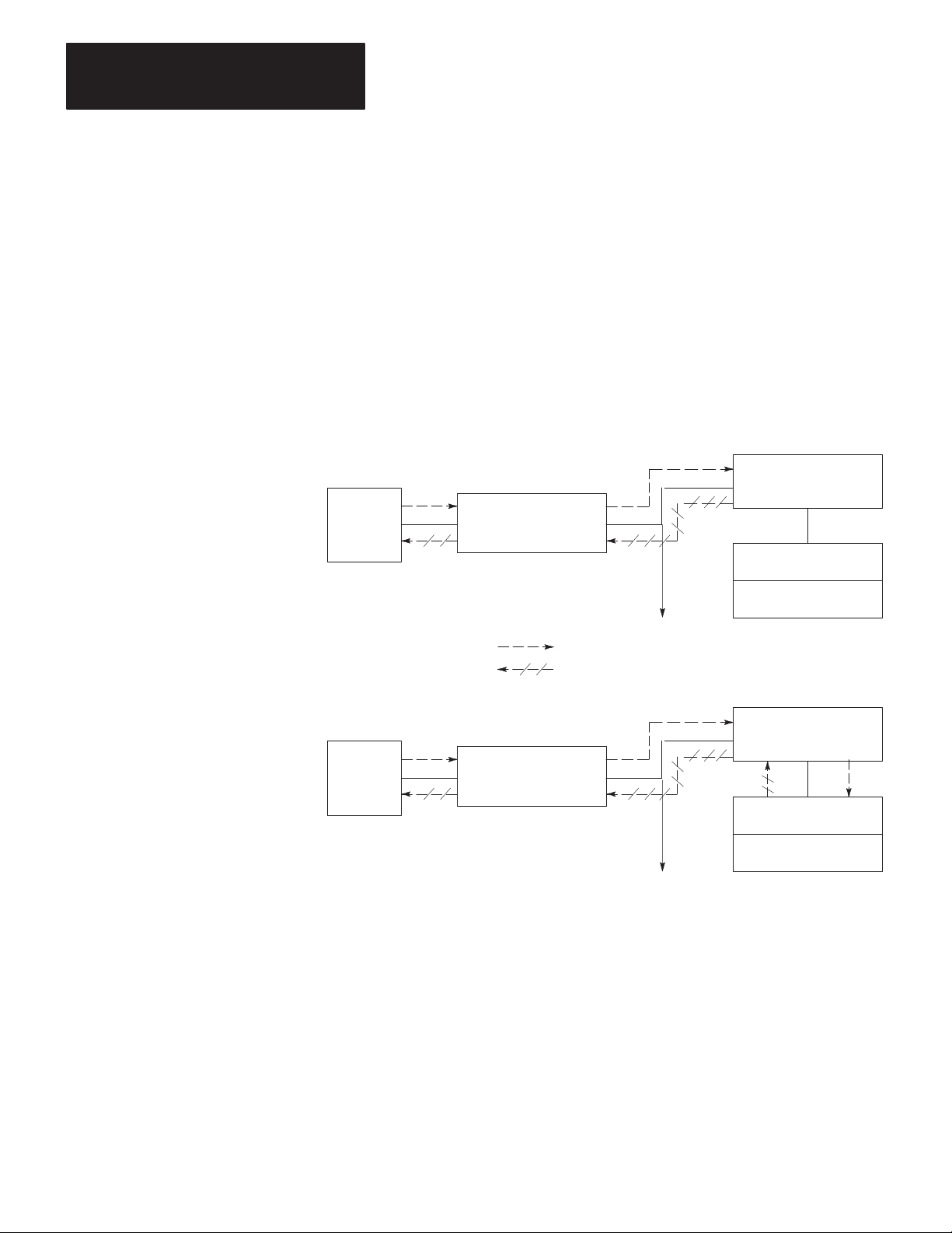
Switch 4 relates only to diagnostic commands sent to the KF2 module
from a remote Data Highway station. Since only computers can transmit
diagnostic commands, the remote station must be a computer connected to
the Data Highway by means of another KF2 module. At the computer
station, the setting of Switch 4 does not affect any diagnostic commands
that the computer sends to its local KF2 module. The local module
always retransmits the command message over the Data Highway without
executing it. Figure 3.4 illustrates these concepts.
Figure 3.4
Effect
of Switch 4 on Diagnostic Commands
Switch 4 ON
1770-KF2 Module
Computer
Diagnostic Command Path
Reply Message Path
Computer
1770-KF2 Module
1770-KF2 Module
Data
Highway
Link
T
o Other Stations
Data
Highway
Link
T
o Other Stations
1771-KG Module
PLC-2/15 Processor
Switch 4 OFF
1770-KF2 Module
1771-KG Module
PLC-2/15 Processor
11691
You can have more than one computer station on a network, and one
computer can transmit diagnostic commands to the others. At the
receiving computer station, if Switch 4 is OFF, the local KF2 module will
pass the diagnostic commands to the computer. In such cases, you will
have to write computer application programs to handle those commands at
the receiving station. If Switch 4 is ON at the receiving station, the local
KF2 module itself will execute the incoming diagnostic commands.
3-6
Page 31

Chapter 3
Installation
Selecting the Network Link
You use Switch Assembly SW-7, a spare assembly in all Series A
modules, to select whether the KF2 treats the network link as a Data
Highway or as a PCL.
The following table shows the settings for Switch Assembly SW-7:
For
This Network:
Data Highway
Peer Communication Link
Set Switch 1: Set Switch 2:
OFF OFF
ON OFF
Selection of RS-232-C/RS-422-A
Switch Assembly SW-8 lets you select whether the asynchronous
interface uses RS-232-C or RS-422-A standard communication.
For
Communication Using Standard:
RS-232-C OFF ON
RS-422-A ON OFF
Set Switch 1: Set Switch 2:
Important: This is the only option switch that affects KF2 operation
after power-up. It changes the voltage applied to the network link
connector pins to those required for the standard selected. Set this switch
BEFORE power-up.
Replacing a 1771-KD Module with a KF2 Module
By setting the switches properly on the KF2 module, you can use it to
replace an older 1771-KD module in an existing application without
having to make any changes in your application programs.
In Set
Switch Ass’y
SW-1 1 OFF
SW-2 1, 2 Same Setting as 1771-KD Switches (Assembly SW-2, Switches 1 and 2)
SW-3 1, 2, 3 Same Setting as 1771-KD Switches (Assembly SW-3, Switches 1, 2, and 3)
SW-4 1, 2, 3 Same Setting as 1771-KD Switches (Assembly SW-4, Switches 1, 2, and 3)
SW-5 1, 2 Same Setting as 1771-KD Switches (Assembly SW-5, Switches 1 and 2)
SW-6 1, 2, 3 Same Setting as 1771-KD Switches (Assembly SW-6, Switches 1, 2, and 3)
SW-7 1, 2 OFF
SW-8 1 OFF
Switch
No.
2 Same Setting as 1771-KD Switch (Assembly SW-1, Switch 1)
3 OFF
4 OFF
5 OFF
4 Same Setting as 1771-KD Switch (Assembly SW-1, Switch 5)
2 ON
Setting
3-7
Page 32

Chapter 3
Installation
Important: The asynchronous port of the KF2 module can communicate
at a maximum rate of 9,600 bits per second. If your 1771-KD module
was set to communicate at a higher rate, then you might have to make
some modifications to your RS-232-C link before installing the
replacement KF2 module.
Mounting (Placing)
A KF2 module is not actually mounted in the sense that other
Allen-Bradley communication modules are. It is simply situated on a
surface, like a desktop, near a wall plug for AC power. It is set for 115V
operation when it reaches you. Connections to 115V AC and 230V AC
are described below.
Place the KF2 module within 100 cable-feet of the Data Highway
trunkline. If you are connecting the module directly to an RS-232-C
device, you must also mount the module within 50 cable-feet of that
device. If you are using a modem link to connect the KF2 module to the
asynchronous device, then the module and the device may be as far apart
as the modem link will allow. If you are connecting the KF2 directly to
an RS-422-A compatible device, you must mount the module within
4,000 cable-feet of that device.
115V AC Operation
The “power select” switch is above the ON/OFF switch on the module’s
rear panel. Set this switch to “115.” The power cord (approximately
7’4”), supplied with the module, must be plugged into the receptacle at
the right of the ON/OFF switch. Plug the other end of the power cord into
any standard 115V AC power outlet. Switch must be set before
power-up.
3-8
230V AC Operation
Set the “power select” switch to “230.” Do NOT use the power cord
supplied with the module. This cord is not approved for connection to a
230V AC outlet. To guard against electrical shock or fire, the power
supply cord must be approved for 230V AC by Underwriters Laboratories
or a similarly recognized agency. To mate with the receptacle on the
module’s rear panel, the power cord must be terminated in a molded
female connector (CEE 22 Standard V).
Page 33
Chapter 3
Installation
Interface Connections
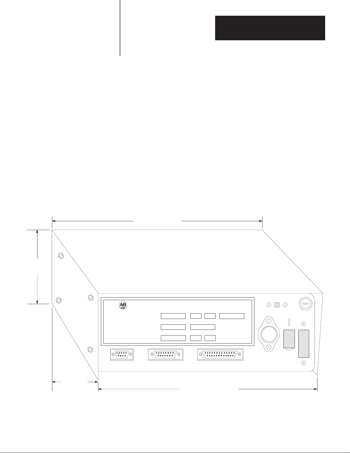
The KF2 module has 3 connectors on its rear panel (Figure 3.5). The
center connector, labeled DATA HIGHWAY, connects to the Data
Highway dropline cable. Plug the 15-pin connector of the dropline into
the DATA HIGHWAY socket. For connection to the PCL, plug the 15-pin
PCL dropline into the Data Highway socket. (For details on how to
construct the dropline, refer to Publications 1770-6.2.1 or 1770-2.13.)
The left connector, labeled DATA HIGHWAY MONITOR, is for future
product development. Do not make any connections to this socket.
The right connector, labeled COMPUTER ASYNCHRONOUS, connects
to an intelligent RS-232-C or RS-422-A compatible device. The rest of
this section explains how to make connections to this asynchronous
socket.
Figure 3.5
Dimensions
of a 1770-KF2 Series B Module
10” (254.0 mm)
3-3/8”
(85.73 mm)
9-1/8”
(231.78 mm)
DATA HIGHWAY COMMUNICATION INTERFACE MODULE
Designed and Manufactured
For
ALLEN-BRADLEY
INDUSTRIAL COMPUTER GROUP
CLEVELAND, OHIO USA
DYNAPRO SYSTEMS INC.
VANCOUVER, B.C. CANADA
DATA HIGHWAY
MONITOR
CO.
By
DATA HIGHWAY COMPUTER
CATALOG NO.
1770-KF2
NO.
MODEL
Prototype
VOLTS
115/230V AC
SERIES REV.
NO.
SERIAL
Marketing
HERTZ
AMPS
0.30
50/60
ASYNCHRONOUS
DATE
June 10/86
MADE IN CANADA
10-3/8” (263.53 mm)
LM323K
∆τ
8428
WARNING
DISCONNECT POWER
BEFORE REMOVING
FUSE OR COVER
3-9
Page 34

Chapter 3
Installation
Mechanical Characteristics
The COMPUTER ASYNCHRONOUS connector on a KF2 module is a
male 25-pin D-shell. This connector conforms to the RS-232-C standard
and will accommodate any RS-232-C standard cable (see “Cabling”).
Electrical Characteristics
Selection of either RS-232-C or RS-422-A determines the input and
output levels of the transmit data and receive data circuits on the
asynchronous interface. When RS-232-C standard communication is
selected, all signals on the asynchronous interface are driven and received
by RS-232-C interface circuits which have a maximum drive capability of
50 cable-feet. When RS-422-A standard communication is selected, the
transmit and receive signals only are driven and received by RS-422-A
interface circuits which have a maximum drive capability of
4,000 cable-feet. In RS-422-A mode, all other signals except transmit and
receive still conform to RS-232-C.
The setting of Communication Option Switch 4 of Switch Group SW-1
determines whether the asynchronous port asserts the handshaking signals
or not (see “Asynchronous Link Features”). The handshaking signals are:
RTS, CTS, DSR, DCD, and DTR. When Switch 4 of SW-1 is ON, the
handshaking signals are used. When RS-422-A communications and
handshaking are both selected, handshaking signals are present; but they
conform to RS-232-C standards only.
Cabling
Cabling for the asynchronous port of the KF2 module will vary,
depending on your application and on whether you are using RS-232-C or
RS-422-A communications. The pinouts for the asynchronous connector
are as follows:
Pin
Signal Abbreviation RS-232-C RS-422-A
Protective Ground
Transmitted Data
Received Data
Request to Send
Clear to Send
Data Set Ready
Signal Ground
Data Carrier Detect
Data Terminal Ready
Transmitted Data A
Transmitted Data B
Received Data A
Received Data B
TXD
RXD
RTS
CTS
DSR
GND
DCD
DTR
TDA
TDB
RDA
RDB
20
1
2
3
4
5
6
7
8
1
14
25
16
18
3-10
Page 35

Chapter 3
Installation
The definitions of the above signals are:
TXD carries serialized data. It is an RS-232-C standard output from
the module.
RXD is RS-232-C standard serialized data input to the module.
RTS is a request from the module to the modem to prepare to transmit.
With full-duplex protocol, RTS is always asserted. With half-duplex
protocol, it is turned on when the module has permission to transmit;
otherwise it is off. It conforms to RS-232-C specifications.
CTS is a signal from the modem to the module that indicates the carrier
is stable and the modem is ready to transmit. The module will not
transmit until CTS is on. If CTS is turned off during transmission, the
module will stop transmitting until CTS is restored. It conforms to
RS-232-C specifications.
DTR is a signal from the module to the modem to connect to the phone
line (i.e., “pick up the phone”). The module will assert DTR all the
time except during the phone hang-up sequence. Modems built to
American standards will not respond to DTR until the phone rings.
Some European modems will always pick up the phone, whether it is
ringing or not. The KF2 module will not work with these types of
European modems. DTR conforms to RS-232-C specifications.
DSR is a signal from the modem to the module that indicates the phone
is off-hook. (It is the modem’s answer to DTR.) The module will not
transmit or receive unless DSR is on. If the modem does not properly
control DSR, or if no modem is used, DSR must be jumpered to a high
signal at the module’s asynchronous connector. (It can be jumpered to
DTR.) DSR conforms to RS-232-C specifications.
DCD is a signal from the modem to the module to indicate that the
carrier from another modem is being sensed on the phone line. It will
not be asserted unless the phone is off-hook. Data will not be received
at the asynchronous connector unless DCD is on. With full-duplex
protocol, the module will not transmit unless DCD is on. If the modem
does not properly control DCD, or if a modem is not being used, DCD
must be jumpered to DTR at the module. DCD conforms to RS-232-C
specifications.
TDA is the transmitted data signal for RS-422-A output from the
module.
TDB is the differential return signal for TDA for transmitting
RS-422-A data.
RDA is the RS-422-A data input to the module.
RDB is the differential return signal for RDA.
If you are connecting a KF2 module to an RS-232-C compatible device
(e.g., modem or computer), then you must mount the module within
50 cable-feet of that device. For such applications, the module’s GND
3-11
Page 36

Chapter 3
Installation
must be connected to the GND of the modem or computer. Note that this
type of connection does not provide electrical isolation between the
module and the connected device.
If a connection is made between the KF2 and an RS-422-A compatible
device, you can mount the device and the module up to 4,000 cable-feet
apart.
Direct Connection to a Computer
To connect the module directly to a computer, you can construct your own
cable according to the wiring diagram in Figure 3.6.A. This cable plugs
into the COMPUTER ASYNCHRONOUS connector on the module and
the RS-232-C or RS-422-A compatible connector on the computer
(Figure 3.6.A). Connect the cable shield at one end only. Be sure that the
cable length does not exceed the RS-232-C limit of 50 feet or the
RS-422-A limit of 4,000 feet.
Figure 3.6
Connection
A. Connection Diagram
B. W
iring Diagram for RS-232-C
Asynchronous
Port Connector
of 1770-KF2 Module
(RS-232-C)
1
7
2
3
6
8
20 6
4
5
25-Pin Female
Connector
3-12
25-Pin Female Connector 25-Pin Male Connector
Asynchronous
Port Connector
of 1770-KF2
Module (RS-232-C)
RS-232-C
Compatible Port
Connector of
Computer
Cable (Not
Exceeding 50 Feet)
25-Pin Male
Connector
to a Computer
Cable
1
Chassis Ground
Signal Ground
7
3
RXD
2
TXD
20
DTR
8
DCD
DSR
4
RTS
CTS
5
RS-232-C or
RS-422-A
Port Connector
of Computer
C. W
iring Diagram for RS-422-A
Asynchronous
Port Connector
of 1770-KF2 Module
(RS-422-A)
1
14
25
16
18
4
5
6
8
20
25-Pin Female
Connector
Compatible
Note:
The connector and the pinouts for
the RS-422-A compatible computer
port will depend on the computer
manufacturer’
Other pins may have to be jumpered
on the computer connector to ensure
proper operation.
RS-422-A
Compatible Port
Connector of
Computer
Cable (Not
Exceeding 4,000 Ft.)
RDA
RDB
TDA
TDB
s standard assignment.
11309
Page 37

Chapter 3
Installation
This type of connection includes the DTR signal to allow each end to
detect the loss of the other end’s ability to communicate. If your
computer does not provide the DTR signal, jump Pins 6 and 8 at the KF2
module to Pin 20.
Connection to a Modem
To connect the module to a modem, you can construct your own cable
according to the wiring diagram in Figure 3.7. This cable plugs into the
COMPUTER ASYNCHRONOUS connector on the module and the
RS-232-C compatible connector on the modem (Figure 3.7). Connect the
cable shield at one end only. Be sure that the cable length does not exceed
the RS-232-C limit of 50 feet.
Figure 3.7
Connection
to a Modem
A. Connection Diagram
25-Pin Female Connector 25-Pin Male Connector
Asynchronous
PORT
Connector
of 1770-KF2
Module (RS-232-C)
B. W
iring Diagram
Asynchronous
Port Connector
of 1770-KF2 Module
(RS-232-C)
1
7
2
3
4
5
Cable
Cable (Not
Exceeding 50 Feet)
RS-232-C
Compatible Port
Connector of
Modem
RS-232-C
Compatible Port
Connector of
Modem
1
7
2
3
4
5
Chassis Ground
Signal Ground
TXD
RXD
RTS
CTS
6
8
20
25-Pin Female
Connector
6
8
20
25-Pin Male
Connector
DSR
DCD
DTR
14831
3-13
Page 38

Chapter 3
Installation
The module can be connected to standard American dial-up modems and
some European modems. Other European standards specify that the DTR
signal will make the modem answer the phone whether it is ringing or not,
causing the phone always to be “busy.” Do not use the module with any
type of modem that answers the phone when DTR is asserted, even while
waiting for a call.
The types of dial-up network modems that you can use are:
Manual: These are typically acoustically coupled modems. The
connection is established by human operators at both ends, who insert
the handsets into couplers to complete the connection.
DTE-Controlled Answer: These unattended modems are directly
connected to the phone lines. The module serves as the data terminal
equipment to control the modem via the DTR, DSR, and DCD signals.
The module incorporates timeouts and tests to properly operate these
types of modems.
Auto-Answer: These modems have self-contained timeouts and tests
and can answer and hang up the phone automatically.
The module has no means of controlling an auto-dial modem, but it can be
used in conjunction with a separate auto-dialer.
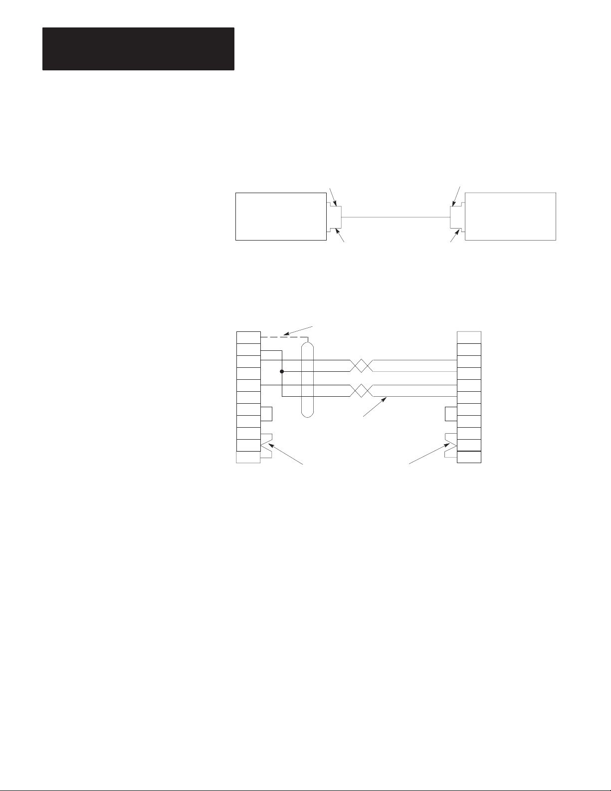
Connection to Another Communication Module
To learn about a direct RS-232-C communication link with a 1771-KE,
-KF, or -KG module, refer to Figure 3.8. To construct the cable, use a
25-pin female connector at the KF2 end and a 15-pin male connector at
the other end.
To provide a direct RS-232-C link with a 1773-KA or a 1775-KA module,
Figure 3.9, use a 25-pin female connector at the KF2 and a 25-pin male
connector at the KA module.
Use Belden 8723 or equivalent cable (available from Allen-Bradley under
Cat. No. 1778-CR). Connect the cable shield at one end only. You can
make the cable up to 50 feet long.
3-14
Page 39
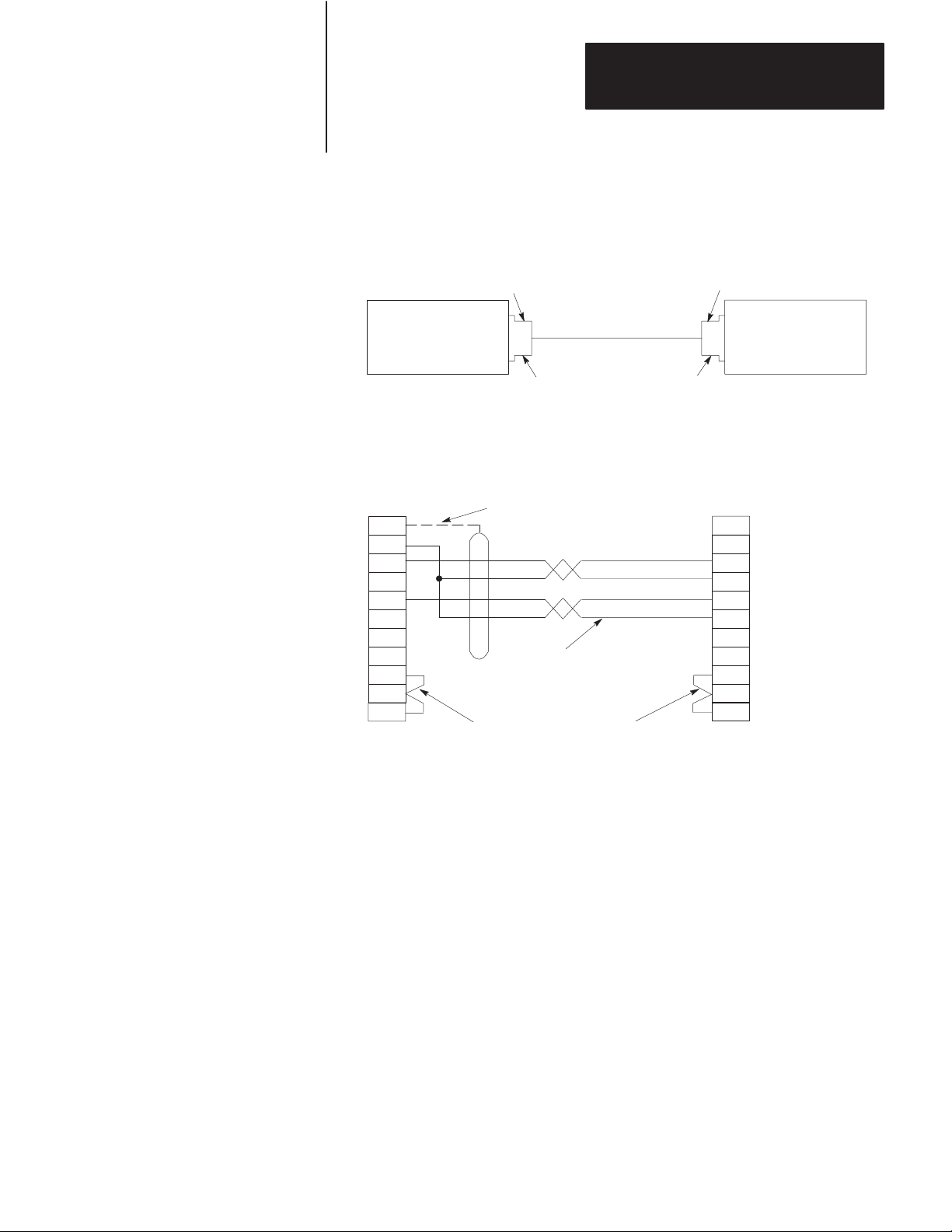
Figure 3.8
Connection
A. Connection Diagram
to 1771-KG Module
Chapter 3
Installation
25-Pin Female Connector 15-Pin Male Connector
Asynchronous
Port Connector
of 1770-KF2
Module (RS-232-C)
B. W
iring Diagram
Asynchronous
Port Connector of
1770-KF2 Module
(RS-232-C)
1
7
2
3
4
5
6
8 8
20
25-Pin Female
Connector
User-Supplied Connectors
User-Supplied Cable,
Belden 8723, or Equivalent
(50 Feet Maximum)
(Cat. No. 1778-CR)
User-Supplied Connectors
Connect the Shield
at One End Only
User-Supplied Cable,
Belden 8723, or Equivalent
(50 Feet Maximum)
RS-232-C
Port Connector
of 1771-KE/KF or
1771-KG Module
RS-232-C
Port Connector
of 1771-KE/KF or
1771-KG Module
1
3
13
2
14
4
5
6
11
15-Pin Male
Connector
Chassis Ground
RXD
TXD
TDA
RTS
CTS
DSR
DCD
11697
3-15
Page 40
Chapter 3
Installation
Figure 3.9
Connection to 1773-KA or 1775-KA Module
A. Connection Diagram
25-Pin Female Connector 25-Pin Male Connector
Asynchronous
Port Connector
of 1770-KF2
Module (RS-232-C)
B. W
iring Diagram
Asynchronous
Port Connector
of 1770-KF2 Module
(RS-232-C)
1
7
2
3
4
5
6
8 8
20
25-Pin Female
Connector
User-Supplied Connectors
User-Supplied Cable,
Belden 8723, or Equivalent
(50 Feet Maximum)
(Cat. No. 1778-CR)
User-Supplied Connectors
Connect the Shield
at One End Only
User-Supplied Cable,
Belden 8723, or Equivalent
(50 Feet Maximum)
RS-232-C
Port Connector
of 1773-KA
1775-KA
Module
25
20
25-Pin Male
Connector
RS-232-C
Port Connector
of 1773-KA
1775-KA
or
1
Chassis Ground
3
RXD
TDB
2
TXD
7
Signal Ground
4
RTS
5
CTS
6
DSR
DCD
DTR
or
Module
11312
3-16
Answering
The module continually asserts DTR when it is waiting for a call. Under
this condition, the modem will answer a call and assert DSR as soon as it
detects ringing. The module does not monitor the RING indicator in the
RS-232 interface. Once it detects DSR, the module starts a timer (around
10 seconds) and waits for the DCD signal. When the module detects
DCD, communication can start.
If the module does not detect DCD within the timeout, the module turns
DTR off. This causes the modem to hang up and break the connection.
When the hang-up is complete, the modem turns off DSR. This causes
the module to reassert the DTR line and wait for another call. This
feature protects access to the phone if someone calling a wrong number
reaches this station.
Page 41

Chapter 3
Installation
After detecting DCD, the module continues to monitor the DCD line. If
DCD goes off, the module restarts the timeout. If DCD is not restored
within the timeout, the module initiates the hang-up sequence. This
feature allows the remote station to redial in the event that the connection
is lost through a fault in the phone network.
This handshaking is necessary to guarantee access to the phone line. If
this handshaking protocol is defeated by improper selection of modem
options or by jumpers at the connectors, the modem may still answer a
call. But if the connection is lost, the modem will not hang up. It will
then be impossible for the remote station to reestablish the connection
because it will get a busy signal.
Character Transmission
The module sends data serially over the asynchronous interface, one 8-bit
byte at a time. The transmission format conforms to ANSI X3.16,
CCITT V.4, and ISO 1177, with the exception that the parity bit is
retained while the data length is extended to eight bits.
The transmission format may be summarized as follows:
start bit
data bit 0
data bit 1
data bit 2
data bit 3
data bit 4
data bit 5
data bit 6
data bit 7
even parity bit (optional)
one stop bit
For communication rate see “Asynchronous Communication Rate and
Diagnostic Commands” and for parity settings refer to “Asynchronous
Link Features.”
3-17
Page 42

Chapter 3
Installation
Diagnostic Indicators
There are 6 LED indicators on the front of a KF2 module (Figure 3.10).
These indicators can help you in diagnosing problems with the module’s
installation and operation. The indicators are:
PWR - Power On
XMTG - Transmitting
RCVG - Receiving
RDY - Ready to Transmit
ACTV - Active
CPU - Module Fault, or DLE NAK Indicator
Figure 3.10
Diagnostic
(LED) Indicators
ALLEN–BRADLEY
DATA HIGHWAY
COMMUNICATION INTERFACE
XMTG RCVG RDY ACTV CPUPWR
The XMTG light comes on when the KF2 module is current master of the
network link and is transmitting a command or reply message.
The RCVG light comes on when the module is receiving a command or
reply message from another station on the network link.
If the KF2 is on the Data Highway and the XMTG and RCVG lights are
on at the same time, this indicates that the module is current master of the
Data Highway and is polling the other stations to transfer mastership.
If the KF2 is on a PCL link and the XMTG and RCVG lights are on at the
same time, this means that the module is determining whether there is a
new module trying to access the link. This is known as “soliciting a
successor.”
The RDY light comes on when the module has a message stored in its
transmit buffer and it is waiting to acquire mastership of the network link
so it can transmit the message.
3-18
Page 43

Chapter 3
Installation
The ACTV light remains on as long as the cable between the
COMPUTER ASYNCHRONOUS socket and the interfacing
asynchronous device is properly connected. This light will appear to
flicker whenever characters are being transmitted across the asynchronous
link. If this light goes off, check the cable and connectors for possible
problems.
The CPU light comes on for about half a second every time the module
transmits or receives a DLE NAK protocol sequence (Chapter 4). If this
light flickers frequently or stays on, the asynchronous link might need
better isolation or noise immunity.
If the KF2 is on a PCL, the CPU light also flashes at about 1 Hz when a
duplicate node (two stations with the same station number) is detected and
stays on when an internal hardware fault is detected. For more on the
KF2 self-diagnostics, see Chapter 1 under “Module Description.”
3-19
Page 44

Chapter
Asynchronous Link Protocols
4
General
Definition of Link Protocol
This chapter describes the communication protocol used on the
asynchronous link to the KF2 module. If you are connecting a KF2
module to another Allen-Bradley communication interface module (such
as a 1771-KG, 1773-KA, or 1775-KA module), you need not be
concerned with protocol because the modules automatically take care of
it. However, if you are connecting a KF2 module to a computer, then you
must program the computer to understand and to issue the proper protocol
character sequences, as described in Chapters 4 through 6 of this manual.
A link consists of a wire and associated hardware—such as transceivers,
UARTs, and error checkers. A link protocol carries a message error-free
from one end of the link to the other, or it indicates failure with an error
code. Internally it delimits messages, detects and signals errors, retries
after errors, and controls message flow. It requires that the link hardware
send characters from one end of the wire to the other.
The only purpose of a link protocol is to carry a message intact over a
link. It has no concern for the content of the message, the message’s
function in the operation of higher levels in the system, or the ultimate
fate or purpose of the message. Once the message has been reliably
carried from one end of the link to the other, the link protocol’s concern
for that message is ended.
The asynchronous port of the KF2 module can use one of two link
protocols, which are:
Full-Duplex Protocol (for Point-to-Point Communication)
Half-Duplex Protocol (for Master-Slave Communication)
In general, full-duplex protocol gives faster data throughput but is harder
to implement; half-duplex protocol is easier to implement but gives
slower data throughput. Each of these protocols is described
independently in “Full-Duplex Protocol” and “Half-Duplex Protocol”
respectively.
4-1
Page 45

Chapter 4
Asynchronous Link Protocols
Important: Some Allen-Bradley documentation might refer to
full-duplex and half-duplex protocols as DF1 and polled-mode protocols,
respectively.
Full-Duplex Protocol
Full-duplex protocol conforms closely to ANSI X3.28-1976, combining
features of Subcategories D1 (data transparency) and F1 (two-way
simultaneous transmission with embedded responses).
Full-duplex protocol is used over a point-to-point link that allows
two-way simultaneous transmission. It is relatively difficult to implement
because it requires a system programmer to use interrupts and
multi-tasking techniques. It is intended for high-performance applications
where it is necessary to get the highest possible throughput from the
available communication medium.
Transmission Codes
Full-duplex protocol is character-oriented; it uses the following ASCII
control characters extended to eight bits by adding a zero for Bit 7. See
ANSI X3.4, CCITT V.3, or ISO 646 for the standard definition of these
characters.
Control
Character Hexadecimal Code
STX (Start of T
ETX (End of T
ENQ (Enquiry)
ACK (Acknowledge)
DLE (Data Link Escape)
NAK (Negative Acknowledge)
ext) 02
ext) 03
05
06
10
15
4-2
The term “code” is defined for use in the following paragraphs as an
indivisible sequence of one or more bytes having a specific meaning to
the link protocol. “Indivisible” means that the component characters of a
code must be sent one after another with no other characters between
them. It does not refer to the timing of the characters.
The following codes are used in full-duplex protocol:
Control Codes:
- DLE STX
- DLE ETX BCC/CRC
- DLE ACK
- DLE NAK
- DLE ENQ
Page 46

Chapter 4
Asynchronous Link Protocols
Data Codes:
- Data (single characters having values 00-0F and 11-FF hex)
- DLE DLE (to represent the value 10 hex)
Codes are grouped into two classes: message codes, sent from transmitter
to receiver; and response codes, sent from receiver to transmitter.
DLE STX is a message code used to indicate the start of a message.
DLE ETX BCC/CRC is a message code used to terminate a message.
Data 00-0F and 11-FF hex are message codes used to encode the
corresponding values in the message itself. DLE DLE is a message
used to encode the occurrence of the value 10 in the message.
DLE ENQ is a message code. It requests the retransmission of the last
received code.
DLE ACK, a response code, signals that a message has been
successfully received.
DLE NAK, also a response code, signals that an attempt to transfer a
message has failed.
Link-Layer Message Packets
A link-layer message packet starts with a DLE STX and ends in a DLE
ETX BCC/CRC, with data codes in between. Data codes can occur only
inside a message packet. Response codes can also occur between a DLE
STX and a DLE ETX BCC/CRC, but such response codes are not part of
the message packet. They are referred to as embedded responses.
Figure 4.1 shows the format of a link-layer message packet for full-duplex
protocol, and the layer at which each portion should be implemented. At
the end of each message packet is the one-byte BCC field.
4-3
Page 47

Chapter 4
Asynchronous Link Protocols
Figure 4.1
Packet
Format for Full-Duplex Protocol
CMD STS Command/Response Block
DST SRC CMD STS TNS
DLE STX
Data
(From Network Layer)
Block Check
(From Application Layer)
Data
DLE ETX
BCC Data Link
From
Application
Layer
From
Network
Layer
Layer Packet
11321A
The block check character (BCC) is a means of checking the accuracy of
each message packet transmission. It is the 2’s complement of the 8-bit
sum (modulo-256 arithmetic sum) of all data bytes between the DLE STX
and the DLE ETX BCC. It does not include any other message packet
codes or response codes.
Example 1: If a message packet contained the data codes 08, 09, 06, 00,
02, 04 and 03, the message packet codes would be (in hex):
10
DLE STX
02 08 09 06 00 02 04 03 10 03 E0
DLE ETX BCCData
4-4
Page 48

Chapter 4
Asynchronous Link Protocols
The sum of the data bytes in this message packet is 20 hex. The BCC is
the 2’s complement of this sum, or E0 hex. This is shown in the
following binary calculation:
0010 0000 20 hex
1101 1111 1’s complement
+1
1110 0000 2’s complement (E0 hex)
Example 2: To transmit the data value 10 hex, you must use the data
code DLE DLE. However, only one of these DLE data bytes is included
in the BCC sum. For example, to transmit the values 08, 09, 06, 00, 10,
04, and 03 hex, you would use the following message codes:
Represents Single Data Byte Value of 10
10
DLE STX
02 08 09 06 00 10 10 04 03 10 03 D2
DLE ETX BCCData
In this case, the sum of the data bytes is 2E hex because only one DLE
text code is included in the BCC. So the BCC is D2 hex.
The BCC algorithm provides a medium level of data security. It cannot
detect transposition of bytes during transmission of a packet. It also
cannot detect the insertion or deletion of data values of zero within a
packet.
Cyclic Redundancy Check
Calculate the CRC value on the value of the data bytes and the ETX byte
16
(using the polynomial x
+ x15 + x2 + x0). To transmit the data value of
10 hex, you must use the data code DLE DLE. However, only one of
these DLE data bytes is included in the CRC value. Embedded responses
are not included in the CRC value.
At the start of a message packet, the transmitter clears a 16-bit register for
the CRC value. As a byte is transmitted, it is exclusive-ORed (with Bit 0
to the right) to the right eight bits of the register. The register is then
shifted right eight times with zeros (0s) inserted on the left. Each time a
one (1) is shifted out on the right the following binary number is
exclusive-ORed with the 16-bit register value:
4-5
Page 49

Chapter 4
Asynchronous Link Protocols
1010 0000 0000 0001
As each additional byte is transmitted, it is included in the value in the
register the same way. After the ETX value is included in the value in the
register and is transmitted, the value in the register is transmitted (right bit
first) as the CRC field.
The receiver also calculates the CRC value and compares it to the
received CRC value to verify the accuracy of the data received.
Two-Way Simultaneous Operation
On a two-way simultaneous link there are only two physical circuits
connecting 4 distinct and independent programs. Referring to the diagram
below, Transmitter A and Receiver B manage the transfer of messages
from Station A to Station B by sending message packets from A to B and
returning responses from B to A. At the same time, Transmitter B and
Receiver A carry out the transfer of messages from Station B to Station A
by sending message packets from B to A and returning responses from A
to B.
Figure 4.2 shows the four independent data paths involved.
Figure 4.2
Data
Paths for T
wo-W
Transmitter
A
Receiver
A
ay Simultaneous Operation
Path 1
Receiver
B
Path 2
Path 3
Transmitter
B
Path 4
11556
Path 1 carries message codes from A to B; Path 2 carries response codes
from B to A; Path 3 carries message codes from B to A; and Path 4 carries
response codes from A to B.
4-6
Page 50
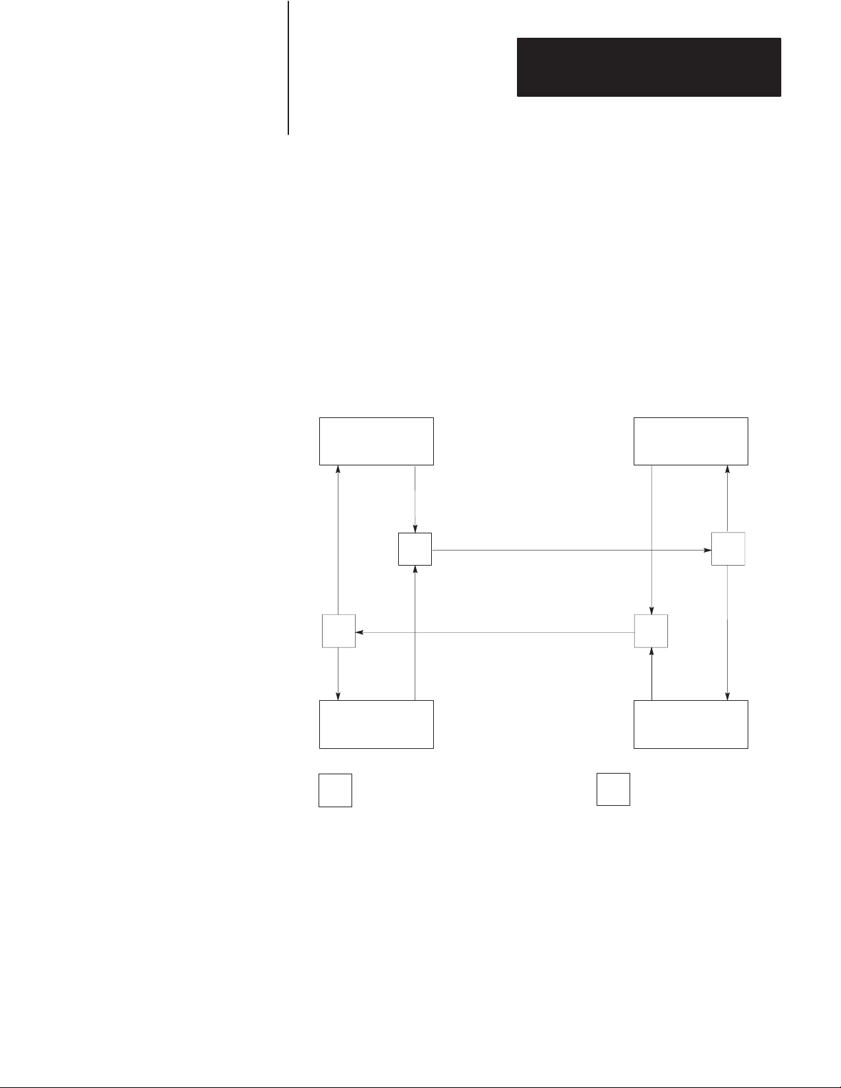
Chapter 4
Asynchronous Link Protocols
To implement all of these data paths with only two physical circuits, a
software multiplexer combines the message codes with the response codes
going in the same direction. At the other end of the link a software
separator divides the message codes from the response codes. The
message codes are sent to the receiver, and the response codes are sent to
the transmitter via internal software. On each physical circuit, response
codes from a receiver to a transmitter will be seen intermingled with
message codes being sent from a transmitter to a receiver. Figure 4.3
shows this implementation.
Figure 4.3
Software
Implementation of Data Paths
Path 2
Path 3
Transmitter
A
M
S
Receiver
A
= Software Multiplexer
M
Path 1
Path 4
Physical Circuit AB
Physical Circuit BA
Receiver
B
Path 2
M
Path 3
Transmitter
B
S = Software Separator
Path 1
S
Path 4
11557
4-7
Page 51

Chapter 4
Asynchronous Link Protocols
Figure 4.4 shows Path 1 with unrelated parts of Figure 4.3 removed.
Paths 2, 3, and 4 could be similarly shown.
Figure 4.4
Path
1, Unrelated Parts of Figure 4.3 Removed
Transmitter
A
Path 1 Path 1
M
Receiver
B
S
11558
The full-duplex protocol is symmetrical; that is, anything that can be said
about Transmitter A, Receiver B, and Paths 1 and 2 applies equally to
Transmitter B, Receiver A, and Paths 3 and 4. There are actually two
independent instances of the protocol operating simultaneously. For
simplicity the protocol will be defined on the subsystem that carries
messages from A to B, with reference to Figure 4.5.
Figure 4.5
Message
Transmission from A to B
4-8
Transmitter
A
Path 2 Path 1 Path 2 Path 1
M
S
Path 1
Path 2
M
Receiver
B
S
11559
Page 52

Chapter 4
Asynchronous Link Protocols
Although the protocols on each subsystem operate independently of each
other, there will be a slight interaction as transmission of a message is
delayed when a two-character response code is inserted in a stream of
message codes. Also, any hardware problem that affects message codes
traveling over a hardware circuit will also likely affect response codes on
the same circuit.
Protocol Environment Definition
To fully define the environment of the protocol, the transmitter needs to
know where to get the message it sends; and the receiver must have a
means of disposing of messages. These are implementation dependent
functions which shall respectively be called the message source and the
message sink.
We assume that the message source supplies one message at a time upon
request from the transmitter and requires notification of the success or
failure of the transfer to Station B before supplying the next message.
When the message source is empty, the transmitter waits in an inactive
state until a message is available. Whenever the receiver has received a
message successfully, it attempts to give it to the message sink. The
possibility exists that the message sink will be full. The receiver requires
an indication of this.
Figure 4.6 shows this representation of the protocol environment.
Figure 4.6
Protocol
Network
Packet
SOURCE SINK
Status Path 2 Full
Transmitter
Environment
A
Path 1
Network
Packet
Receiver
B
Software Software
Hardware
11560
4-9
Page 53

Chapter 4
Asynchronous Link Protocols
Message Characteristics
Ideally the link protocol should not be at all concerned with the content or
form of the message it is transferring. However, full-duplex protocol
places the following restrictions on the messages that are submitted to it
for transfer:
1. Minimum size of a valid message is 6 bytes, maximum is 250 bytes.
2. Some protocol implementations (point-to-point links to a 1771-KG
module, for example) require that the first byte of a message match
the station address. The receiver will ignore messages that do not
contain the correct address.
3. As part of the duplicate message detection algorithm, the receiver
checks the second, third, fifth, and sixth bytes of each message.
There must be a difference in at least one of these bytes between a
message and the previous one for it to be recognized as distinct
rather than a retransmission of the previous message. If Switch 3 of
Switch Group SW-1 if off, the KF2 module does not implement
duplicate message detection (see Chapter 3, “Asynchronous Link
Features”).
Protocol Definition
Whenever the message source can supply a message and the transmitter is
not busy, it sends a message packet on Path 1. It then starts a timeout and
waits for a response on Path 2.
When a DLE ACK is received, the message has been successfully
transferred. After signaling the message source that the message has been
sent, the transmitter proceeds with the next message.
If a DLE NAK is received, the message will be retransmitted. The
transmitter restarts the timeout and waits again for a response. This can
be repeated several times. There is a user-defined limit to the number of
times a message can be retransmitted. If this limit is exceeded, the
message source will be signaled of the failure; and the transmitter will
proceed with the next message.
4-10
Page 54

Chapter 4
Asynchronous Link Protocols
If the timeout expires before a response is received, the transmitter sends
a DLE ENQ on Path 1 to request a retransmission of the last response sent
on Path 2. It restarts the timeout and waits for a response.
This too can be repeated several times, and there is a user-defined limit on
the number of timeouts that are allowed per message. If the enquiry limit
is exceeded, the message source will be signaled that the transmission has
failed, and the transmitter proceeds to the next message.
Since there are only two response codes defined, there are no invalid
response codes. If the separator returns an invalid response code, the
transmitter will ignore it. A more precise and detailed description of the
actions of the transmitter appears in Table 4.A in structured English
procedures. Figure 4.7 is a flowchart of the software logic for
implementing the transmitter.
Figure 4.7
Software
Legend:
Logic for Implementing T
T
Message Packet
DLE STX Data DLE ETX BCC
Received
DLE ACK
?
Yes
T
P = Recovery Procedure
No
ransmitter
Retransmit Same Message
Received
DLE NAK
?
Yes
3*
NAKs
Received for this
Message
?
Yes
imeout Loop
T
No
Yes
P
Timed Out
?
Yes
3*
Timeouts
for this
Message
?
No
No
= Ready to Transmit
T
Next Message
* Default Values Used
by the Module
No
DLE ENQ
11322
4-11
Page 55

Chapter 4
Asynchronous Link Protocols
T
able 4.A
T
ransmitter for Full-Duplex Protocol
TRANSMITTER is defined as
loop
Message = GET-MESSAGE-TO-SEND
Status = TRANSFER (Message)
SIGNAL-RESULTS (Status)
end loop
TRANSFER (Message) is defined as
initialize NAK-limit and ENQ-limit
SEND (Message)
start timeout
loop
WAIT for response on Path 2 or timeout.
if received DLE ACK then return SUCCESS
else if received DLE NAK then
if NAK-limit is exceeded then return FAILURE
else
begin
count NAK retries;
SEND-MESSAGE (Message);
start timeout
end
end
else if timeout
if ENQ-limit is exceeded then return FAILURE
else
begin
count ENQ retries;
send DLE ENQ on Path 1;
start timeout
end
end
end loop
4-12
SEND (Message) is defined as
begin
BCC = 0
send DLE STX on Path 1
for every byte in the message do
begin
add the byte to the BCC;
send the corresponding data code on Path 1
end
send DLE ETX BCC on Path 1
end
GET-MESSAGE-TO-SEND
This is an operating-system-dependent interface routine that waits and allows the rest
of the system to run until the message source has supplied a message to be sent.
SIGNAL-RESULTS
This is an implementation-dependent routine that tells the message source of the results
of the attempted message transfer.
WAIT
This is an operating-system-dependent routine that waits for any of several events to
occur while allowing other parts of the system to run.
Page 56

Chapter 4
Asynchronous Link Protocols
Receiver Actions
Since the receiver gets “dirty” input from the physical world, it is more
complex and must be capable of responding to many adverse situations.
Some of the things that can conceivably happen are listed here:
1. The message sink can be full, leaving the receiver with nowhere to
put a message.
2. A message can contain a parity error.
3. The BCC can be invalid.
4. The DLE STX or DLE ETX BCC may be missing.
5. The message can be too long or too short.
6. A spurious control or data code can occur outside a message.
7. A spurious control code can occur inside a message.
8. The DLE ACK response can be lost, causing the transmitter to send a
duplicate copy of a message that has already passed to the message
sink.
A record of the last response sent on Path 2 is kept. The value of this
response is either ACK or NAK. It is initialized to NAK. When a DLE
ENQ is received, the receiver sends the value of the last response from
this variable.
A record is kept of several message header bytes. If a message has the
same header as the previous message, the message is ACKed but
discarded.
The receiver ignores all input from Path 1 until a DLE STX or a DLE
ENQ is received. If anything other than a DLE STX or DLE ENQ is
received on Path 1, the receiver sets the last response variable to a NAK.
If an ENQ is received, the last response is sent on Path 2; and the receiver
continues waiting for input.
4-13
Page 57

Chapter 4
Asynchronous Link Protocols
If a DLE STX is received, the BCC and the message buffer are reset; and
the receiver starts building a message.
While building a message, all data codes are stored in the message buffer
and added to the BCC. If the buffer overflows, the receiver continues
summing the BCC, but the data is discarded. If a parity, overrun, framing,
or modem handshaking error is detected, it is recorded. If any control
codes other than a DLE EXT BCC are received, the message is aborted
and a DLE NAK sent on Path 2. When the DLE ETX BCC is received,
the error flag, the BCC, the message size, and the address (optionally) are
all checked. If any of the tests fail, a DLE NAK is sent on Path 2.
If the message is OK, its header is compared to the last message. If it is
the same, the message is discarded; and a DLE ACK is sent. (Duplicate
message detection is not implemented if Switch 1 of Switch Group SW-1
is turned off.)
If the message is different from the last one, the state of the message sink
is tested. If the message sink is full, a DLE NAK is sent; otherwise the
message is forwarded to the message sink; the header information is saved
for the duplicate message detector; and a DLE ACK is sent.
The procedure for the 1771-KC/KD and 1771-KG (Revision C) modules
is different. First, they check the message sink state. If the sink is full,
the response is recorded but not sent. The receiver waits for a DLE ENQ
on Path 1. If any other code is received, the response is changed from
ACK to NAK and the receiver continues waiting for a DLE ENQ. If a
DLE ENQ is received, the sink status is checked. If it is still full, the
receiver continues waiting. If it is not full, the last response is sent; and
the receiver then accepts new messages. This variation is not documented
in the structured English section found in Table 4.B.
The receiver for the KF2 module is listed in Table 4.B in structured
English. Figure 4.8 is a flowchart of the software logic for implementing
the receiver.
4-14
Page 58

T
able 4.B
Receiver
Chapter 4
Asynchronous Link Protocols
for Full-Duplex Protocol
RECEIVER
GET
GET
is defined as
variables
LAST
-HEADER is 4 bytes copied out of the last good message
RESPONSE is the value of the last ACK or NAK sent
BCC is an 8-bit block check accumulator
LAST
-HEADER = Invalid
LAST
-RESPONSE = NAK
loop
reset parity error flag
GET-CODE
if DLE STX then
begin
BCC = 0
GET-CODE
while it is a data code
begin
if buf
fer is not overflowed put data in buf
GET-CODE
end
if the control code is not a DLE ETX then send DLE NAK
else if error flag is set then send DLE NAK
else if BCC is not zero then send DLE NAK
else if message is too small then send DLE NAK
else if message is too large then send DLE NAK
else if header is same as last message send a DLE ACK
else if message sink is full send DLE NAK
else
begin
send message to message sink
send a DLE ACK
save last header
end
end
else if DLE ENQ then send LAST
else LAST
end loop
-CODE is defined as
loop
-CHAR is defined as
an implementation-dependent function that returns one byte of data from the link interface hardware.
-RESPONSE = NAK
GET-CHAR
if char is not a DLE
begin
add char to BCC
return the char and data flag
end
else
begin
GET-CHAR
if char is a DLE
begin
add char to BCC
return a DLE and a data flag
end
else if char is an ACK or NAK send it to the transmitter
else if char is an ETX
begin
GET-CHAR
add char to BCC
return ETX with a control flag
end
else return character with a control flag
end
end loop
-RESPONSE
fer
4-15
Page 59
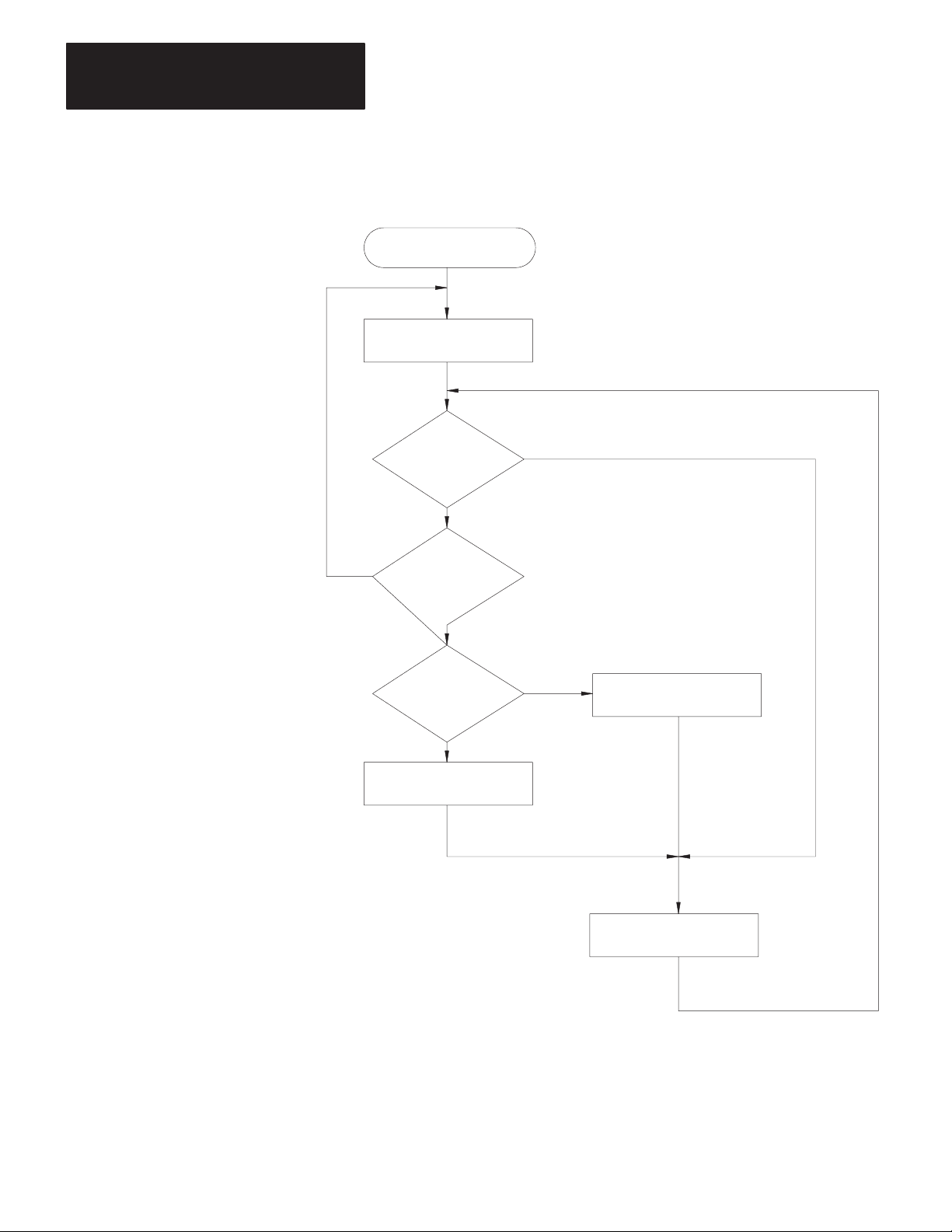
Chapter 4
Asynchronous Link Protocols
Figure 4.8
Receiver
for Full-Duplex Protocol
RCVE
LAST = NAK
No
Receive
DLE
ENQ
?
No
Receive
Message
?
Yes
BCC/CRC
OK
?
Yes
LAST = ACK
Yes
No
LAST = NAK
4-16
Send DLE LAST
11699
Page 60

Chapter 4
Asynchronous Link Protocols
Full-Duplex Protocol Diagrams
The following figures show some events that can occur on the various
interfaces. Time is represented as increasing from the top of the figure to
the bottom. Data bytes are represented by “xxxx”; corrupted data by
“???”.
Figure 4.9
Normal
Message T
SOURCE XMTR LINK RCVR SINK
xxxx
DLE STX xxxx DLE ETX BCC
ransfer
Not Full
DLE ACK
OK
Figure 4.10
Message T
SOURCE XMTR LINK RCVR SINK
xxxx
DLE STX x??x DLE EXT BCC
DLE STX xxxx DLE ETX BCC
ransfer with NAK
DLE NAK
xxxx
11561
OK
Not Full
xxxx
DLE ACK
11562
4-17
Page 61

Chapter 4
Asynchronous Link Protocols
Figure 4.1
Message T
SOURCE XMTR LINK RCVR SINK
xxxx
DLE STX xxxx DLE EXT BCC
(Timeout)
OK
1
ransfer with Timeout and ENQ
DL
??? CK
DLE ENQ
DLE ACK
Not Full
xxxx
Figure 4.12
Message T
ransfer with Retransmission
11563
SOURCE XMTR LINK RCVR SINK
xxxx
DLE STX xxxx DLE EXT BCC
Not Full
xxxx
??? CK
DL
???
(Timeout)
DLE ENQ
DLE NAK
OK
DLE STX xxxx DLE EXT BCC
DLE ACK
1
Note that this is detected as a duplicate message.
(Message Discarded)
1
11564
4-18
Page 62

Chapter 4
Asynchronous Link Protocols
Figure 4.13
Message T
SOURCE XMTR LINK RCVR SINK
xxxx
DLE STX xxxx DLE EXT BCC
DLE STX xxxx DLE ETX BCC
ransfer with Message Sink Full
Full
DLE NAK
Full
OK
DLE NAK
DLE STX xxxx DLE EXT BCC
Not Full
xxxx
DLE ACK
11565
Retransmission occurs when noise hits both sides of the line. This type of
noise destroys the DLE ACK while also producing invalid characters at
the receiver. The result is that the receiver changes its last response to
NAK and the transmitter retransmits the original message. Note that this
is detected as a duplicate message if Switch 1 of Switch Group SW-1 is
on.
4-19
Page 63

Chapter 4
Asynchronous Link Protocols
Examples
If a line monitor were connected to the wires between Stations A and B,
and only the A to B subsystem were active, the following would be
observed:
Normal Message
Path 1:
Message with Parity or BCC Error and Recovery
Path 2: DLE ACK
Message with ETX Destroyed
Path 1:
Path 2: DLE NAK DLE ACK
Good Message but ACK Destroyed
Path 1:
Path 2:
Messages Being Sent in Both Directions
Path 1:
Path 2:
Path 3:
Path 4:
DLE STX ... DLE ETX BCC
DLE ACKPath 2:
DLE STX ...xxx.. DLE ETX BCC
DLE STX .....xxxx [timeout] DLE ENQ
DLE STX ... DLE ETX BCC
DL xxx CK
DLE STX ... DLE ETX BCC DLE STX .... DLE ETX BCC
DLE ACK DLE ACK
DLE STX ...
DLE STX .... DLE ETX BCC
DLE STX .... DLE ETX BCCPath 1:
DLE NAK
DLE STX .... DLE ETX BCC
[timeout] DLE ENQ DLE STX ... etc.
DLE ACK
DLE ACK
DLE STX
DLE STX.... DLE ETX BCC
DLE ACK
4-20
Combined
DLE STX ... DLE ETX BCCCircuit AB: DLE STX .... DLE ETX BCC DLE ACK DLE STX
Circuit BA: DLE STX ... DLE ACK .... DLE ETX BCC DLE ACK DLE STX
Embedded Response
ACK on AB delayed slightly because ETX BCC are indivisible.
Embedded Response Option
To simplify the design of the receiver, you can, in some cases, disable
transmission of embedded responses by turning off communication option
Switch 2 of Switch Group SW-1. If this switch is OFF, the KF2 module’s
multiplexer will not allow response codes to be sent within a message.
Instead, it will delay response codes until after it receives the next DLE
ETX BCC.
Page 64

Chapter 4
Asynchronous Link Protocols
Half-Duplex Protocol
Half-duplex protocol is the alternative to full-duplex protocol. You can
select half-duplex protocol by setting communication option Switches 1,
2, and 5 of SW-1. Half-duplex protocol is based on full-duplex but
extends or redefines several features.
Half-duplex protocol is a multi-drop protocol for one master and one or
more slaves. Modems must be used (unless there is only one slave). KF2
modules have slave mode capability only; the master function must be
provided by a user-programmed intelligent device.
Half-duplex protocol provides a lower effective utilization of resources
than full-duplex, but it is much easier to implement. Its use is indicated
by the following:
Multiple stations and a single computer are connected in a multi-drop
configuration using multi-drop modems.
Half-duplex modems are being used.
It is desirable to sacrifice throughput in exchange for ease of
implementation.
Half-duplex protocol requires the following communication
characteristics:
8 Bits per Character
Even Parity
1 Stop Bit
Pass-All Mode (The terminal driver does not translate or respond to
control characters.)
Single Character Buffer (The terminal driver immediately returns each
character to the caller.)
Multi-Drop Topology
The intended environment for half-duplex protocol is a multi-drop link
with all stations interfaced through half-duplex modems. The actual
nature of the link does not matter much, as long as the modems support
request-to-send, clear-to-send, and data-carrier-detect signals. If dial-up
modems are used, they must also support data-set-ready and
data-terminal-ready; otherwise, DSR should be jumpered to DTR.
There may be from 2 to 256 stations simultaneously connected to a single
link. Each station has a receiver permanently connected to the circuit and
a transmitter that may be enabled or disabled by RTS.
4-21
Page 65

Chapter 4
Asynchronous Link Protocols
One station is designated as master, and it controls which station has
access to the link. You can use a 1771-KGM PLC-2 Family module as
the master, or this function can be performed by your own programmed
intelligent device. All other stations are called slaves and must wait for
permission from the master before transmitting. Each slave station has a
unique station number from 0 to 254.
The master can send and receive messages to and from each station on the
multi-drop. The master can send and receive messages to and from every
station on highways that are connected to the multi-drop via a KF2
module. If the master is programmed to relay messages, then stations on
the multi-drop can engage in peer-to-peer communications. The
multi-drop will not easily provide flexible peer-to-peer communication
between the multi-drop and connected highways, or between different
highways.
Either a two-circuit system (master sends and slaves receive on one
circuit, slaves send and master receives on the other), or a one-circuit
system (master and slaves send and receive on the same circuit) can be
used.
Half-duplex dial-up modems can be used as long as a carrier is detected
before the carrier timeout (about 8 seconds). If a carrier is not sensed
before the timeout, the module will hang up the phone. Carrier must be
sensed at least every 8 seconds to maintain the connection.
Multiple masters are not allowed, except when one acts as a backup to the
other and does not communicate unless the primary is shut down.
Transmission Codes
Half-duplex protocol is a character-oriented protocol that uses the
following ASCII control characters extended to 8 bits by adding a zero for
Bit 7. See ANSI X3.4, CCITT V.3, or ISO 646 for the standard definition
of these characters.
4-22
Control
Character Hexadecimal Code
SOH (Start of Header)
STX (Start of T
ETX (End of T
EOT (End of T
ENQ (Enquiry)
ACK (Acknowledge)
DLE (Data Link Escape)
NAK (Negative Acknowledge)
ext)
ext)
ransmission)
01
02
03
04
05
06
10
15
Page 66

Chapter 4
Asynchronous Link Protocols
The term “code” means (in the following paragraphs) an indivisible
sequence of one or more bytes having a specific meaning to the link
protocol. “Indivisible” means that the component characters of a code
must be sent one after another with no other characters inserted between
them. It does not refer to the timing of the characters. (This definition
has less significance than for full-duplex protocol since there is no
multiplexing of transmission codes in half-duplex protocol.)
These codes are used in half-duplex protocol:
Control Codes:
- DLE SOH
- DLE STX
- DLE ETX BCC/CRC
- DLE ACK
- DLE NAK
- DLE ENQ
- DLE EOT
Data Codes:
- DATA (single characters having values 00-0F and 11-FF hex)
- DLE DLE (to represent the value 10 hex)
DLE SOH indicates the start of a message.
DLE STX separates the link level header from the data field of a message.
DLE ETX BCC/CRC terminates a message.
DATA 00-0F and 11-FF encode the corresponding values in the message
itself. DLE DLE encodes the occurrence of the value 10 in the message.
DLE ACK signals that a message has been successfully received.
DLE NAK is used as a global link reset command and can be issued only
by the master. It causes all slaves to cancel all messages that are ready to
be transmitted to the master. Typically the slave will return the messages
to the command originator with an error code.
DLE ENQ starts a poll command.
DLE EOT is used by slaves as a response to a poll when they have no
messages to send.
4-23
Page 67
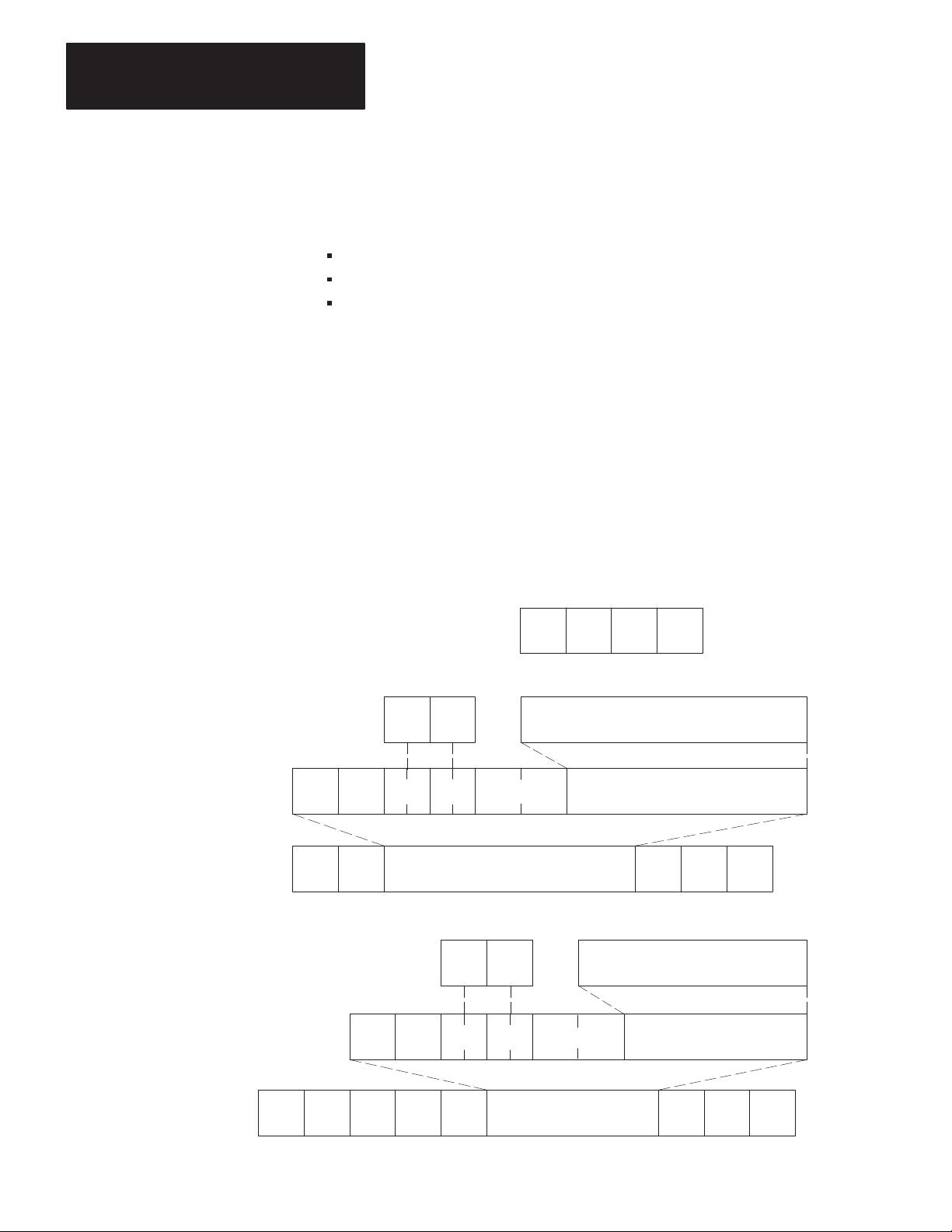
Chapter 4
Asynchronous Link Protocols
Link-Layer Packets
Half-duplex protocol uses three types of transmissions:
Polling Packet
Master Message Packet
Slave Message Packet
The master station transmits both polling packets and master message
packets, while slave stations transmit slave message packets.
Figure 4.14 illustrates the formats of these packets. Note that the slave
message packet has the same format as the full-duplex message packet
(see “Link-Layer Message Packets”). The master message packet is the
same as the slave message packet except that it is prefixed with DLE SOH
and an address code to specify a slave station number.
Figure 4.14
Packet
Formats for Half-Duplex Protocol
A. Polling Packet
B. Slave Message Link Packet
CMD STS Command/Response Block
DST SRC CMD STS TNS
DLE STX
C. Master Message Link Packet
Data
(From Network Layer)
CMD STS
DLE ENQ STN BCC
Data
(From Application Layer)
DLE ETX
Command/Response Block
BCC
From
Application
Layer
From
Network
Layer
Data Link
Layer Packet
From
Application
Layer
4-24
DST SRC CMD STS TNS
DLE SOH STN DLE STX
Data
(From Network Layer)
(From Application Layer)
Data
DLE ETX
BCC
From
Network
Layer
Data Link
Layer Packet
11327
Page 68

Chapter 4
Asynchronous Link Protocols
At the end of each polling packet there is a BCC byte. At the end of each
message packet, there is either a one-byte BCC field or a two-byte CRC
field. You can select BCC or CRC through switch settings (see Chapter 3,
“Asynchronous Link Features”).
Block Check
The block check character (BCC) is a means of checking the accuracy of
each packet transmission. It is the 2’s complement of the 8-bit sum
(modulo-256 arithmetic sum) of the slave station number (STN) and all
the data bytes in the packet. For polling packets, the BCC is simply the
2’s complement of STN. The BCC does not include any other message
packet codes or response codes.
Example 1: If the master station wanted to send the data codes 08, 09,
06, 00, 02, 04, and 03 to Slave Station 20 hex (40 octal), the master
message codes would be (in hex):
10
01
DLE SOH
20
STN
02
DLE10STX
08 09 06 00 02 04 03 10 03 C0
DLE ETX BCCData
The sum of the STN and data bytes in this message packet is 40 hex. The
BCC is the 2’s complement of this sum, or C0 hex. This is shown in the
following binary calculation:
0100 0000 40 hex
1011 1111 1’s complement
+1
1100 0000 2’s complement (C0 hex)
Example 2: To transmit the STN or data value 10 hex, you must use the
data code DLE DLE. However, only one of these DLE text characters is
included in the BCC sum. For example, to transmit the values 08, 09, 06,
00, 10, 04, and 03 hex, a slave station would use the following message
codes:
Represents Single Text Value of 10
10
02 08 09 06 00 10 10 04 03 10 03 D2
DLE STX
DLE ETX BCCData
4-25
Page 69

Chapter 4
Asynchronous Link Protocols
In this case, the sum of the data bytes is 2E hex because only one DLE
text code is included in the BCC. So the BCC is D2 hex.
The BCC algorithm provides a medium level of data security. It cannot
detect transposition of bytes during transmission of a packet. It also
cannot detect the insertion or deletion of data values of zero within a
packet.
Cyclic Redundancy Check
Calculate the CRC value on the value of the data bytes and the ETX byte
16
(using the polynomial x
+ x15 + x2 + x0). To transmit the data value of
10 hex, you must use the data code DLE DLE. However, only one of
these DLE data bytes is included in the CRC value. Embedded responses
are not included in the CRC value.
At the start of a message packet, the transmitter clears a 16-bit register for
the CRC value. As a byte is transmitted, it is exclusive-ORed (with Bit 0
to the right) to the right eight bits of the register. The register is then
shifted right eight times with zeros (0s) inserted on the left. Each time a
one (1) is shifted out on the right, the following binary number is
exclusive-ORed with the 16-bit register value:
1010 0000 0000 0001
As each additional byte is transmitted, it is included in the value in the
register the same way. After the ETX value is included in the value in the
register and is transmitted, the value in the register is transmitted (right bit
first) as the CRC field.
The receiver also calculates the CRC value and compares it to the
received CRC value to verify the accuracy of the data received.
Important: In half-duplex mode there is a BCC on the polling packet
regardless of whether BCC or CRC error checking is used on messages.
4-26
Master/Slave Transceiver
In each station there is a program associated with the physical link called
the transceiver. The master station has a more complex transceiver than
the slave, since it must include a polling algorithm. The slave’s
Page 70

Chapter 4
Asynchronous Link Protocols
transceiver is illustrated in Figure 4.15, and the master transceiver is
illustrated in Figure 4.16.
To fully define the environment of the protocol, the transceiver needs to
know where to get the messages it sends and must have a means of
disposing of messages it receives. These are implementation-dependent
functions that shall respectively be called the message source and the
message sink.
We assume that the message source will supply one message at a time
upon request from the transceiver and will require notification of the
success or failure of transfer before supplying the next message.
When the transceiver has received a message successfully, it will attempt
to give it to the message sink. The possibility exists that the message sink
will be full. The transceiver requires an indication of this.
Figure 4.15
Slave Transceiver
Network
Packet
SOURCE SOURCE
OK OK
Network
SINK SINK
Packet
Full
Software Software
MASTER
TRANSCEIVER
Link
SLAVE
RECEIVER
To Other Slaves
Hardware
Network
Packet
Network
Packet
Full
Message Characteristics
Ideally, the link protocol should not be at all concerned with the content or
form of the messages it is transferring. However, half-duplex protocol
places the following restrictions on the messages that are submitted to it
for transfer:
11566
1. Minimum size of a valid message is 6 bytes, maximum is 250 bytes.
4-27
Page 71

Chapter 4
Asynchronous Link Protocols
2. Some protocol implementations require that the first byte of a
message match the station address. These receivers will ignore
messages that do not contain the correct address. This filtering is not
required, since the message sink can also provide the address
filtering function.
3. As part of the duplicate message detection algorithm, the receiver
checks the second, third, fifth, and sixth bytes of each message.
There must be a difference in at least one of these bytes between a
message and its predecessor for it to be recognized as distinct rather
than a retransmission of the previous message.
Master Polling Responsibilities
The master polling algorithm may vary depending on the expected flow of
traffic through the system.
A simple master that does not expect unsolicited messages continuously
polls each slave once in a round-robin fashion. If a message is received, it
should be handled, then the next station polled. An alternative scheme
would poll each station repeatedly until it was empty and then proceed to
the next. Relaying of peer-to-peer messages is best left to the network
layer, which is the lowest level of the body of software that includes the
message source and sink.
Figure 4.16 is a flowchart of the software logic for implementing
half-duplex protocol from the master station’s point of view.
4-28
Page 72

XCVR
Select Station
Figure 4.16
Half-Duplex
Master T
Chapter 4
Asynchronous Link Protocols
ransceiver
Poll Selected Station
Start Timeout
Receive
DLE EOT
?
Yes
Set Active Station Flag
No
Network
Layer has
Message to
send?
Yes
Get Message from
Network Layer
Send Message
Station to Poll
Is Master?
Send Poll
No
No
YesNo
Receive
Message
?
No
Active
Station
Yes
Yes
Message
OK?
Yes
Duplicate
Message
?
No
Create Master Message
Is Message
for Master
?
No
Yes
Start Timeout
Receive
DLE ACK
No
Timeouts
for this
Message?
Tell Network Layer
of Failure
No
Send to
Network Layer
Yes
?
No
3
Yes
Timeouts
for this Poll?
Remove Station
from Active List
Send Message
to Destination
3
Yes
Send DLE ACK
No
Yes
11698
4-29
Page 73

Chapter 4
Asynchronous Link Protocols
Slave Transceiver Actions
Since the transceiver receives “dirty” input from the physical world, it
must be capable of responding to many adverse situations. Some of the
things that could conceivably happen are listed below:
1. The message sink can be full, leaving nowhere to put a message.
2. A message can contain a parity error.
3. The BCC can be invalid.
4. The DLE SOH, DLE STX, or DLE ETX BCC may be missing.
5. The message can be too long or too short.
6. A spurious control or data code can occur outside a message.
7. A spurious control code can occur inside a message.
8. The DLE ACK response can be lost, causing the transmitter to send a
duplicate copy of a message that has already been passed to the
message sink.
The slave is always in a passive mode until it receives a message. While
waiting for a message, anything besides the DLE SOH or DLE ENQ is
ignored. Note that in a single circuit system the slaves must be able to
safely ignore everything sent by other slaves.
If a DLE SOH is received, the BCC and the message buffer are reset. The
next code received must be a data code and must equal the station address
or 255 (if the station can receive broadcast messages). If there is no
match, the station ignores the rest of the message and continues waiting
for the start of the message.
4-30
If the station address matches, it is added to the BCC. The next code is
received and must match DLE STX. If it doesn’t, the station ignores the
rest of the message. Otherwise it starts building a message.
While building a message, all data codes are stored in the message buffer
and added to the BCC. If the buffer overflows, the receiver continues
Page 74

Chapter 4
Asynchronous Link Protocols
summing the BCC, but the data is discarded. If an error is detected, it is
recorded. If any control code other than a DLE ETX BCC is received, the
error flag, the BCC, the message size, and the address (optionally) are all
checked. If any of the tests fail, the message is ignored.
If the message is OK, its header is compared to the last message. If it is
the same, the message is discarded and a DLE ACK is transmitted. If it is
different, the new header is saved and the message is sent to the message
sink. If the message can be stored, a DLE ACK is sent. If the message
sink is full, the message is discarded and not acknowledged.
If while waiting for a message a DLE ENQ is received, the transceiver
accepts the next two characters. The last character is read directly from
the link, since it is a BCC and is not byte stuffed. If the station address
does not match or there is an error, the poll is ignored. If the poll is
accepted, there are three possible situations:
1. The transceiver could still be holding a message that it had
transmitted previously but had not been ACKed. There is a limit on
the number of times each message can be sent. If this limit is
exceeded when the poll is received, the message is returned to the
message source with an error indication, and the transceiver tries to
send the next message from the message source. If the limit is not
exceeded, the response to the poll will be to resend the current
message.
2. If no message is currently being held, the transceiver tries to get one
from the message source. If one is available, the transceiver will
initialize its retry counter and transmit it in response to the poll.
3. If no message is available, the response to a poll will be to transmit a
DLE EOT.
When a message is transmitted after receiving a poll, its format is
identical to a full-duplex message packet. After sending a message, the
transceiver will hold the message until a DLE ACK is received, or the
number of times the message has been polled exceeds the limit.
When a DLE ACK is received, the message currently held is discarded.
When the next poll is received, the next message available from the
message source is sent (or a DLE EOT).
4-31
Page 75
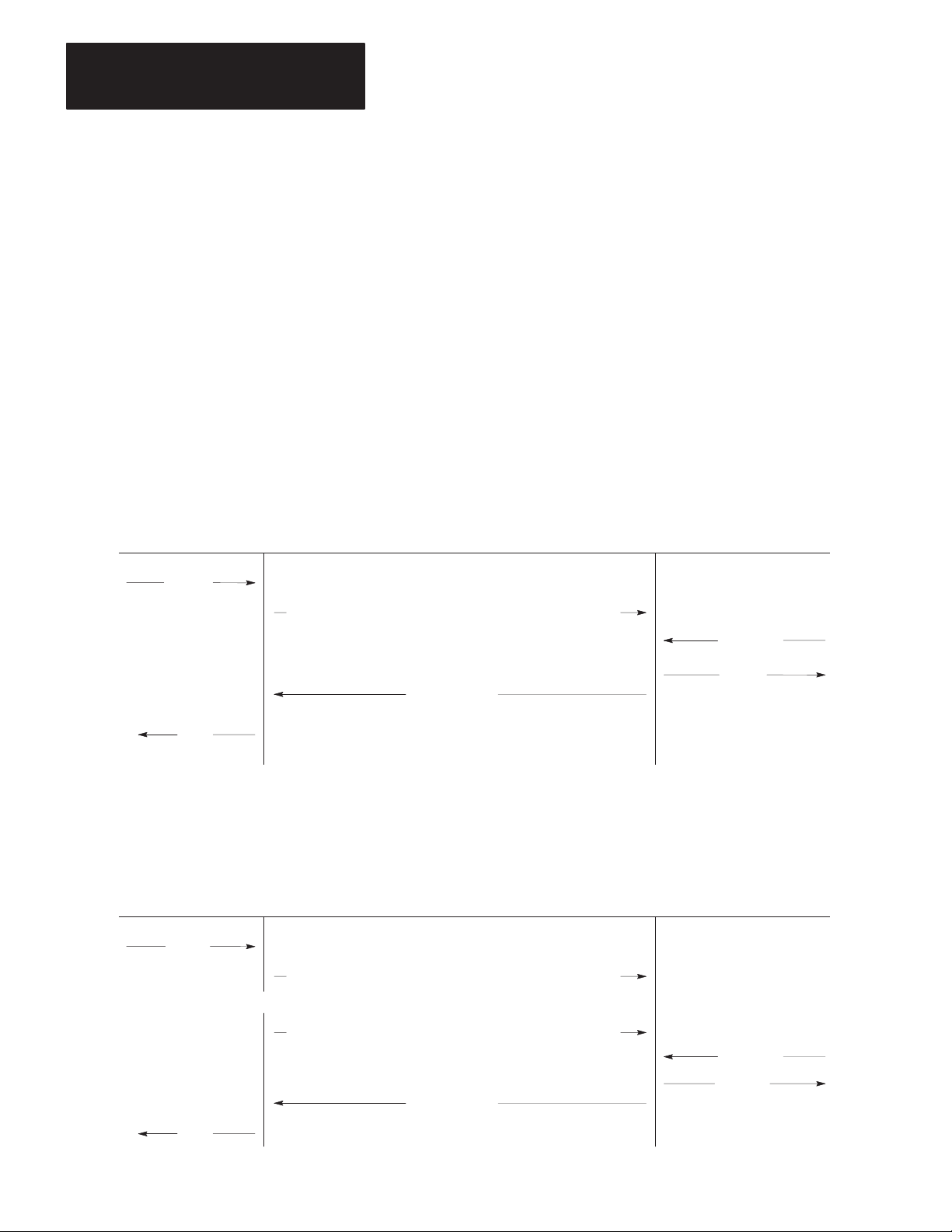
Chapter 4
Asynchronous Link Protocols
When a DLE NAK is received, the transceiver takes messages from the
source until it is empty. Each message will be discarded with an error
code sent back to the message source. This can be used by the master to
clear up the message source buffers of all slaves after the master has been
down.
Half-Duplex Protocol Diagrams
The following figures show some of the events that occur on various
interfaces. Time is represented as increasing from the top of the figure to
the bottom.
Figure 4.17
Normal
Message T
ransfer
SOURCE/ SOURCE/
SINK MASTER LINK SLAVE SINK
xxxx
DLE SOH STN
OK
DLE STX xxxx DLE ETX BCC
Not Full
xxxx
DLE ACK
Figure 4.18
Message T
SOURCE/ SOURCE/
SINK MASTER LINK SLAVE SINK
xxxx
DLE SOH STN
ransfer with Invalid BCC
DLE STX ??? DLE ETX BCC
11567
4-32
OK
(Timeout)
DLE STX xxxx DLE ETX BCCDLE SOH STN
Not Full
xxxx
DLE ACK
11568
Page 76

Chapter 4
Asynchronous Link Protocols
Figure 4.19
Message T
SOURCE/ SOURCE/
SINK MASTER LINK SLAVE SINK
xxxx
(Timeout)
OK
ransfer with ACK Destroyed
DLE STX xxxx DLE ETX BCCDLE SOH STN
Not Full
xxxx
DL ??? CK
DLE STX xxxx DLE ETX BCCDLE SOH STN
DLE ACK
11569
Figure 4.20
Poll with No Message A
SOURCE/ SOURCE/
SINK MASTER LINK SLAVE SINK
Not Full
DLE EOT
vailable
BCCDLE ENQ STN
No Message
11570
Figure 4.21
Poll with Message Returned
SOURCE/ SOURCE/
SINK MASTER LINK SLAVE SINK
Not Full
BCCDLE ENQ STN
xxxx
DLE STX xx???xx DLE ETX BCC
xxxx
BCCDLE ENQ STN
DLE STX xxxx DLE EXT BCC
DLE ACK
Same Message
OK
11571
4-33
Page 77

Chapter 4
Asynchronous Link Protocols
SOURCE/ SOURCE/
SINK MASTER LINK SLAVE SINK
Not Full
xxxx
Sometime Later ...
Not Full
Figure 4.22
Duplicate Message T
DLE STX xxxx DLE ETX BCC
DLE STX xxxx DLE ETX BCC
ransmission
BCCDLE ENQ STN
DL ??? CK
BCCDLE ENQ STN
xxxx
DLE ACK
(Discard Retransmission)
OK
Figure 4.23
Message Sink Full, Case 1
SOURCE/ SOURCE/
SINK MASTER LINK SLAVE SINK
xxxx
DLE STX xxxx DLE ETX
(Timeout)
Not Full
BCCDLE ENQ STN
DLE EOT
Sometime Later ...
BCCDLE SOH STN
Full
No Message
11572
4-34
BCCDLE SOH STN DLE STX xxxx DLE ETX
Not Full
xxxx
DLE ACK
OK
11573
Page 78

Chapter 4
Asynchronous Link Protocols
Figure 4.24
Message Sink Full, Case 2
SOURCE/ SOURCE/
SINK MASTER LINK SLAVE SINK
xxxx
Not Full
xxxx
(Timeout)
DLE STX xxxx DLE ETX
DLE STX
xxxx DLE ETX BCC
DLE ACK
BCCDLE ENQ STN
BCCDLE SOH STN
Full
xxxx
BCCDLE SOH STN DLE STX xxxx DLE ETX
Not Full
OK
xxxx
DLE ACK
11575
The message sent for the second poll is the same as the first, since the first
transmission was not ACKed. Also, the master should ACK and discard
the second message, since it was a retransmission. This means that the
master must either poll a station repeatedly until it receives a DLE EOT,
without polling any other stations, to be sure it has detected all
retransmissions.
If each station is polled only once per cycle, the master must keep a
record of the last header from each station, since other stations may
transfer messages between retransmissions from a station.
When a station times out, it is a good idea to poll it to see if it is there. If
it answers with a DLE EOT to a message, but consistently fails to a ACK
a message, its message sink is probably full. If it responds DLE EOT to a
poll, you must wait for the buffers to clear.
When a station’s message source and sink share a common memory pool,
it may be that the message sink “full” indication results from an
abundance of messages in the message source, which use up all free pool
memory. In this case, the memory can be freed up by receiving messages
from the station. Waiting for the memory to clear by the action of the
4-35
Page 79

Chapter 4
Asynchronous Link Protocols
station alone may not work, since it could be that the only way to free up
space is to send a message to the master.
Line Monitoring
When monitoring half-duplex protocol in two-wire mode, you need to
monitor only one line. The example below shows a message sent by the
master and a reply sent by the slave in answer to a poll. Slave responses
are in boldface.
Message from Master to Slave:
DLE SOH STN DLE STX message DLE ETX BCC DLE ACK
Message Sent from Slave to Master in Response to Poll:
DLE ENQ STN BCC DLE STX message DLE ETX BCC DLE ACK
Poll with a DLE EOT in Response:
DLE ENQ STN BCC DLE EOT
4-36
Page 80

Message Packet Formats
Chapter
5
General
Application Layer
This chapter describes how your computer application programs should
format command and reply messages for transmission over the
asynchronous link. It covers both application level and network level
functions. Basically, the application layer specifies the contents of
messages and initiates their transmissions. The network layer takes the
information from the application layer and formats it in a way that is
acceptable to the data link layer (Chapter 4).
There are two types of application programs: command initiators and
command executors. These names correspond with the two message
types:
Command Messages — Sent by command initiators to command
executors.
Reply Messages — Sent by command executors in response to
command messages received from command initiators.
Each command message requires one reply message.
Command initiators specify which command function to execute at a
particular destination station. The command executor at that destination
station is responsible for interpreting the command message and
executing the specified command function. The command executor also
issues a reply message for each command it receives. If it cannot execute
the received command, the command executor must generate the
appropriate error message.
Network Layer
Internally, the KF2 module uses a routing subroutine and a message queue
to implement the network layer. When the module receives a message
over its asynchronous port, it puts that message in the queue. The routing
subroutine then takes the message from the queue and transmits it over the
Data Highway link. The module also queues messages received from the
Data Highway, and the routing subroutine retransmits those messages
over the asynchronous link. Figure 5.1 illustrates this model.
5-1
Page 81
Chapter 5
Message Packet Formats
Figure 5.1
Network
Model
Command
Initiator
QQ
Commands
Replies
RR
Network
RQ= Routing Subroutine Entry = Incoming Message Queue
Replies
Command
Executor
Commands
11576
Messages do not necessarily arrive at their destination in the same order
that they were sent. It is impossible for the network layer to guarantee
delivery, and in some cases it may not be possible to provide notification
of non-delivery.
5-2
In particular, the network layer does not notify the command executor
about non-delivery of a reply message. Therefore, it is advisable that your
command initiator maintain a timer for each outstanding command
message. If the time limit expires before the command initiator receives
the corresponding reply to its command, it can either retransmit the same
command message or indicate an error condition.
If your network layer software cannot deliver a command message, it
should generate a reply message with an error code in it and send that
reply to the command initiator. If it cannot deliver a reply message, the
network layer software should simply destroy the reply without
notification to the command executor.
If your link layer software cannot deliver a message over the
asynchronous link, it also should return an error message to the command
initiator.
Page 82

Chapter 5
Message Packet Formats
Message Packets
The message bytes contain unsigned binary data from both the application
layer and the network layer. Figure 5.2 shows the general format of a
command message.
Figure 5.2
Command
DST SRC CMD STS TNS
Message Packet Format
CMD STS FNC
x
(0)
0x
Legend: x = low hex digit of CMD byte supplied by application layer
00
ADDR
Command Block
SIZE OR
DATA0
From
Application
Layer
Network
Layer
Packet
11329A
Not all command messages have FNC, ADDR, SIZE, or DATA bytes.
Figure 5.3 shows the general format of a reply message. The definitions
of these bytes are the same as those for command messages. Not all reply
messages have DATA or EXT STS bytes.
Figure 5.3
Reply
Message Packet Format
CMD STS DATA
x
DST SRC CMD STS TNS
4x
Legend: x = low hex digit of CMD byte supplied by application layer
EXT
STS
Response Block
(From Application Layer)
Note that the bytes are shown from left to right in the order in which they
are transmitted across the link.
From
Application
Layer
Network
Layer
Packet
11330A
5-3
Page 83

Chapter 5
Message Packet Formats
The meanings of the bytes are:
DST — Destination Station for the Message
SRC — Source Station of the Message
CMD — Command Code
STS — Status Code
TNS — Transaction Number (2 Bytes)
FNC — Function Code
EXT STS — Extended Status Code
ADDR — Address of Memory Location (2 Bytes Minimum)
SIZE — Number of Bytes to Be Transferred
DATA — Data Values Being Transferred by the Message
These bytes are described in more detail below.
DST and SRC
The DST (destination) byte contains the station number of the station that
is the ultimate destination of the message. The SRC (source) byte is the
station number of the station that originated the message.
The network layer supplies the DST and SRC values. Allowed values for
these bytes are 0 to 254 decimal (0 to 376 octal). Note that you can form
the DST and SRC bytes of a reply message simply by interchanging the
DST and SRC bytes of the corresponding command message.
In application programming of a computer connected to the network by a
KF2, the SRC byte should be set to zero. The module will set the byte to
its own station number.
CMD and FNC
The CMD (command) and FNC (function) bytes together define the
activity to be performed by the command message at the destination
station. CMD defines the command type; and FNC, if used, defines the
specific function under that command type.
5-4
Table 5.A lists all the available CMD and FNC codes in hexadecimal
notation. The exact format for a particular message depends on the CMD
and FNC values. “Message Formats” explains the use of each command
or function and gives a detailed description of the message text format for
each.
Page 84

Chapter 5
Message Packet Formats
Figure 5.4 shows the format for the CMD byte itself. Bits 0 through 3
contain the command code. Bits 4 and 7 should always be set to 0. Bit 5
is the priority indicator; set to 0 for normal priority messages and 1 for
high priority messages (Chapter 2). Bit 6 is the command/reply indicator;
set it to 0 in a command message and 1 in a reply message.
Figure 5.4
CMD
Byte Format
76543210Bit
0 r p 0 command
11702
Reply messages also contain a CMD byte. To form the CMD value for a
reply, the network layer copies the CMD value from the corresponding
command message and sets the reply bit (Bit 6) to 1.
The application layer supplies the FNC value and the command code (Bits
0 to 3) of the CMD byte for each command message. The network layer
supplies Bits 4 through 7 of the CMD byte.
STS and EXT STS
The STS (status) and EXT STS (extended status) bytes indicate the status
of the message transmission. In command messages, the application
program should always set the STS value to 0. In reply messages, the
STS byte may contain one of the status codes listed in Chapter 7. If the
four high bits of that byte are 1s (0F hex), there is extended status
information in an EXT STS byte. Otherwise, there is no EXT STS byte.
Note that an STS value of 0 in a reply message means “no error.”
In a reply message, the STS byte is divided between application layer and
network layer. The network layer uses Bits 0 through 3 of the STS byte to
report local errors (those errors that occur when the network layer
attempts to transmit a message across the link).
The application layer uses Bits 4 through 7 of the STS byte (and in some
cases the EXT STS byte), to report remote errors (those errors that occur
when the command executor at the destination station tries to execute the
command message). Chapter 7 explains local and remote error codes.
5-5
Page 85

Chapter 5
Message Packet Formats
TNS
A complete transaction consists of a command message transmitted by a
PC station. The TNS (transaction) bytes contain a a unique 16-bit
transaction identifier. The first byte, RNG, contains the number of the PC
program rung that generated the command; and the second, SQN, contains
the transmission sequence number. For command messages transmitted
by your computer station, your application programs can use the RNG and
SQN bytes together to store a single 16-bit transaction number.
For command messages transmitted by a PC station, the station interface
module assigns the TNS values. For each command message transmitted
by your computer station, your network level software must assign a
unique 16-bit transaction number; and a simple way to generate this
number is to maintain a 16-bit counter at the network layer. Increment the
counter every time your command initiator (application program) creates
a new message and store the counter value in the two TNS bytes of the
new message.
When the command initiator receives a reply to one of its command
messages, it can use the RNG and SQN bytes to tie the reply message to
its corresponding command. If the RNG and SQN bytes of a reply
message match the RNG and SQN bytes of a command message, then that
reply is the appropriate one for that command.
Whenever the command executor receives a command from another
station, it should copy the RNG and SQN fields of the command message
into the same fields of the corresponding reply message. Do not change
the RNG and SQN values in a reply message. If you do, the command
initiator will not be able to match its command to the corresponding reply
message.
Note that the low byte (least significant bits) of your TNS value will be
transmitted across the link before the high byte (most significant bits).
At any instant, the combination of SRC, CMD, RNG, and SQN are
sufficient to uniquely identify every message packet in transit. At least
one of these fields in the current message must be different than the
corresponding field in the last message received by a command executor.
If none of these fields is different, the command executor ignores the
currently received message. This process is called duplicate message
detection.
5-6
Page 86

Chapter 5
Message Packet Formats
ADDR
The ADDR (address) field contains the address of a memory location in
the command executor. ADDR specifies the address where the command
is to begin executing. For example, if the command is to read data from
the command executor, ADDR specifies the address of the first byte of
data to be read.
Note that the ADDR field specifies a byte address, not a word address as
in PC programming. Chapter 6 explains how to convert PC word
addresses to byte addresses.
SIZE
The SIZE byte specifies the number of data bytes to be transferred by a
message. This field appears in read commands, where it specifies the
number of data bytes that the responding station must return in its reply
message. The allowed value for SIZE will vary with the type of
command, as indicated in the command formats below.
Message Formats
DATA
The DATA field contains binary data from the application program. The
number of data bytes in a message depends on the command or function
being executed, as indicated in “Message Formats.” Chapter 6 gives some
details on the format for the data field.
This section presents the detailed message formats for each type of
command and reply message. PLC-5 processors cannot be interfaced
directly with the Data Highway; they work only on Peer Communication
Link (PCL) networks. To access a PLC-5 from a Data Highway station,
join the two networks with a 1785-KA PLC-5/Data Highway adapter
module. In this manual, the command message formats are discussed in
the same order as Table 5.A:
5-7
Page 87

Chapter 5
Message Packet Formats
If Y
ou W
ant This
Command:
T
Message
Use This
CMD Code:
able 5.A
Formats
Use This
FNC Code:
If Y
ou W
Command:
ant This
Use This
CMD Code:
Use This
FNC Code:
Basic Command Set
Diagnostic Counters Reset
Diagnostic Loop
Diagnostic Read
Diagnostic Status
Protected Bit W
Protected W
Set ENQs
Set NAKs
Set T
imeout
Set V
ariables
Unprotected Bit W
Unprotected Read
Unprotected W
Disable Outputs
Enable Program
Enable Scan
Physical Read
Physical W
Enter Download Mode
Enter Upload Mode
Exit Download/Upload Mode
Physical Read
Physical W
Set Data Table Size
rite
rite
rite
rite
rite
PLC-2 Commands
rite
PLC-3 Commands PLC-5 Commands
06
06
06
06
02
00
06
06
06
06
05
01
08
PLC Commands
07
07
07
04
03
07
07
07
04
03
06
07
00
01
03
N/A
N/A
06
05
04
02
N/A
N/A
N/A
00
01
03
N/A
N/A
04
06
05
N/A
N/A
08
PLC-4 Commands
Allocate
Deallocate
Initialize Processor
Physical Read
Physical W
Physical Write with Mask
Set to Program Mode
Set to Run Mode
Set to Single-Step Test Mode
Set to Test Mode
rite
0E
0E
0E
0E
0E
0E
0E
0E
0E
0E
05
06
0C
0D
0E
0F
01
02
04
03
Bit W
rites
Download Request
File Read
File W
rite
Physical Read
Physical W
Restart Request
Shutdown Request
Upload Request
W
ord Range Read
W
ord Range W
5-8
rite
rite
0F
0F
0F
0F
0F
0F
0F
0F
0F
0F
0F
02
05
04
03
09
08
0A
07
06
01
00
Download All Request
Download Completed
Modify PLC-2 Compat. File
Read Bytes Physical
Read-Modify-Write
Set Processor Mode
T
yped Read
T
yped W
Upload All Request
Upload Completed
W
W
W
rite
rite Bytes Physical
ord Range Read
ord Range W
rite
0F
0F
0F
0F
0F
0F
0F
0F
0F
0F
0F
0F
0F
Important: In the example formats that follow, CMD and FNC values
are expressed in hexadecimal notation; all other values are in decimal
form.
50
52
5E
17
26
3A
68
67
53
55
18
01
00
Page 88

Chapter 5
Message Packet Formats
Basic Command Set
Basic commands include those that can generally be executed by any PC
station on the communication link, regardless of the type of PC controller
at that station. In some cases, switch settings on the station interface
module can disable execution of a particular type of command at that
station. For more details, refer to the user’s manual for the station
interface module.
Basic commands are in two categories:
Privileged:
Computer
•
•
•
•
•
•
•
•
initiates. PCs execute.
Diagnostic Counters Reset
Diagnostic Loop
Diagnostic Read
Diagnostic Status
Set ENQs
Set NAKs
Set T
imeout
Set V
ariables
Non-Privileged:
PC stations and computer can initiate;
only PCs can execute (unless the
computer is programmed for execution).
•
Protected Bit W
•
Protected W
•
Unprotected Bit W
•
Unprotected Read
•
Unprotected W
rite
rite
rite
rite
Diagnostic Counters Reset
This command resets to zero all the diagnostic timers and counters in the
station interface module. The diagnostic status command gives the
starting address for this block of counters and timers.
Command
Format:
SRCDST FNC
06
TNSSTSCMD
07
Reply Format:
SRCDST
TNSSTSCMD
46
5-9
Page 89
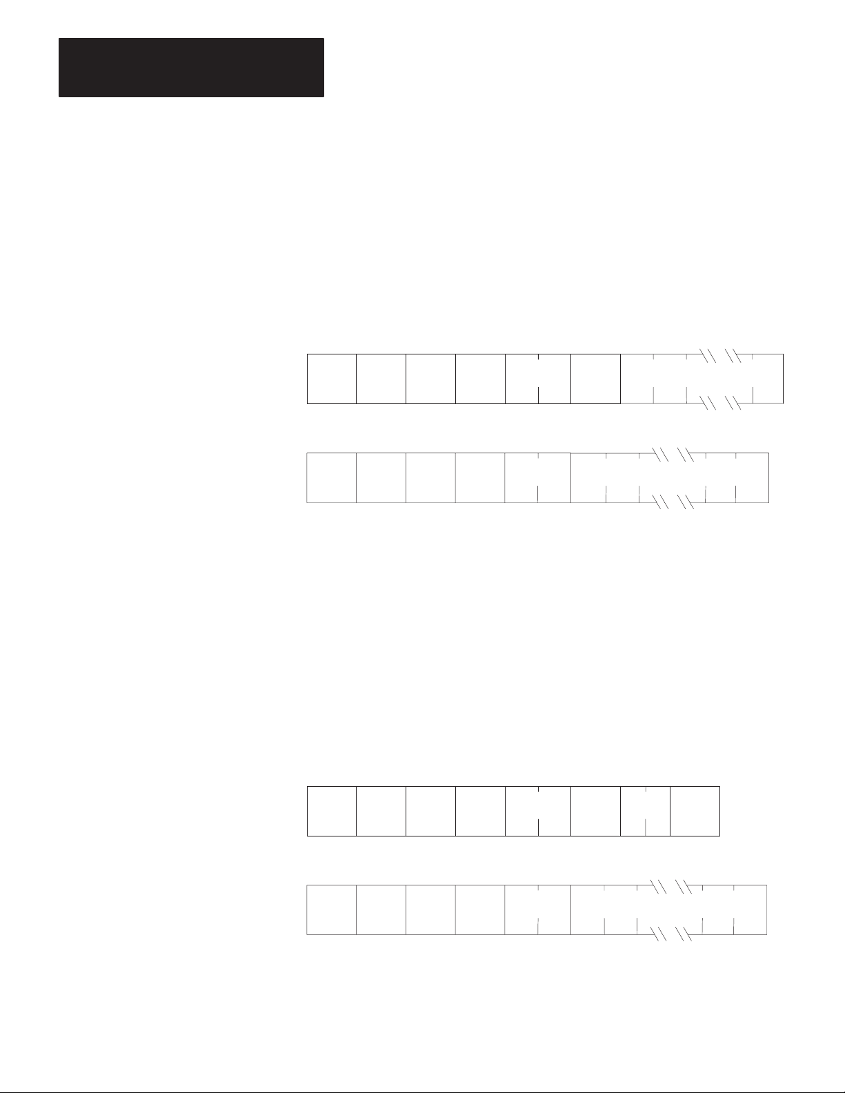
Chapter 5
Message Packet Formats
Diagnostic Loop
You can use this command to check the integrity of transmissions over the
communication link. The command message transmits up to 243 bytes of
data to a station interface module. The receiving module should reply to
this command by transmitting the same data back to the originating
station.
Command
Reply Format:
Format:
SRCDST FNC
06
SRCDST
46
TNSSTSCMD
TNSSTSCMD
DATA
— Max. 243 Bytes
00
DATA
— Max. of 243 Bytes
Diagnostic Read
This command reads up to 244 bytes of data from the PROM or RAM of
the station interface module. You can use it to read the module’s
diagnostic timers and counters. Except for the PLC-5, you must use the
diagnostic status command to obtain the starting address of the diagnostic
counters. The PLC-5 doesn’t require that this address be specified,
though you must include a dummy value in the ADDR field, which the
PLC-5 will ignore.
5-10
Command
Reply Format:
Format:
SRCDST FNC
SRCDST
06
46
TNSSTSCMD
01
TNSSTSCMD
DATA
ADDR
— Max. of 244 Bytes
SIZE
Page 90

Chapter 5
Message Packet Formats
Diagnostic Status
This command reads a block of status information from the station
interface module. The reply to this command contains the status
information in its DATA field.
Command
Reply Format:
Format:
SRCDST FNC
06
SRCDST DATA
46
TNSSTSCMD
03
TNSSTSCMD
— Max. of 244 Bytes
The status information varies with the type of station interface module.
Table 5.B describes the contents of the status DATA field for 1771-KA,
1771-KC/KD, 1771-KE/KF, 1770-KF2, 1771-KG, 1774-KA, and
1785-KA modules. Table 5.C lists the status DATA for 1773-KA
modules. Table 5.D describes this DATA for 1775-KA modules.
Table 5.E describes this DATA for the PLC-5.
5-11
Page 91

Chapter 5
Message Packet Formats
5-12
T
able 5.B
Contents
of Status DATA for 1771-KA2, -KC/KD, -KE/KF; 1770-KF2; 1771-KG, 1774-KA; and
1785-KA Modules
Byte Bit Value Meaning
1 Operating
2
3-4 Octal W
5-6
7-8
9
10
Status of PC Processor — For the 1770-KF2, this byte is always 0. For the 1785-KA, it has one of these values:
0 =
0-2 0
3 0
4 0
5 0
6, 7
T
ype of Station Interface Module and Processor
NOTE:
The 1770-KF2 identifies itself as a station interface module with a “3” in Byte 2, Bits 0 to 3 (i.e., as a 1771-KE/KF).
0-3 0
4-7 0
ord Address of the Start of PC Program — For the KF2 module, these are always 0. For the 1785-KA module, these are the
expansions of the interface module type bits and the processor type bits, respectively
Memory Size (Number of Bytes) for PLC Processors; Zero Otherwise — For the 1785-KA module, this is the starting address of the counters on
the link other than the one from which the diagnostic read command was issued.
Starting Byte Address of Diagnostic Counters and T
from which the diagnostic read command was issued.
Series and Revision Level of Station Interface Module
NOTE:
The Series A 1770-KF2 identifies itself as Series “D” in Byte 9, Bits 5 to 7.; Series B KF2 identifies itself as Series E; and so on.
0-4
5-7
Settings of the Option Switches on the Station Interface Module — This byte is not used in replies by 1771-KC/KD or -KE/KF modules. For the
other modules, the bits of this byte are defined as follows:
0-1 0
2 0
3 0
4 0
5 -- Not Used
6 0
7 0
Standby Mode
1
2
3
4
5
1
1
1
1
2
3
4
5
6
7
8
9
10
11
12
13
14
15
1
2
3
4
5
6
7
8
9
10
11
12
13
14
15
0
1
0
1
1
2
3
1
1
1
1
1
Program Load Mode
T
est Mode
Run Mode
(Not Used)
Remote Program Load
Remote T
Normal
No Communication with PC
Normal
Download Mode
Normal
Format Error in Communication Zone of PC Program
Always Zero
1771-KC/KD Module
1771-KA Module
1774-KA Module
1771-KE/KF or 1770-KF2 Module
1771-KG Module
1771-KGM Module
1775-KA, Data Highway Port
1775-KA, RS-232-C Port
1773-KA, Data Highway Port
1773-KA, RS-232-C Port
(Unused)
PLC-5 Processor Interface
(Unused)
(Unused)
Check Interface Module Expansion Byte (Byte 3)
Computer
PLC Processor
PLC-2 Processor
PLC-2/20 (LP1) Processor
Mini-PLC-2 Processor
PLC-3 Processor
PLC-2/20 (LP2) Processor
PLC-2/15 Processor
PLC-2/30 Processor
PLC-4 Microtrol Processor
(Not Used)
(Not Used)
PLC-5 Processor Interface
(Not Used)
(Not Used)
Check Processor Expansion Byte (Byte 4)
Computer
Revision A
Revision B, etc.
Series A
Series B, etc.
57,600 Bits per Second
Undefined
Undefined
Undefined
All Other PLC-2 Family Processors
PLC-2 Processor
Protected Commands Enabled
Protected Commands Disabled
Unprotected Commands Enabled
Unprotected Commands Disabled
Physical Writes Enabled
Physical Writes Disabled
T
ransmission Unprotected Commands Enabled
T
ransmission Unprotected Commands Disabled
1 =
On-Line Mode
est
. Both have a value of 16.
imers — For the 1785-KA module, this is the starting address of the counters on the link
1771-KA2 MODULE
Page 92

Chapter 5
Message Packet Formats
Table
5.B Continued
Contents of Status DATA for 1771-KA2, -KC/KD, -KE/KF; 1770-KF2; 1771-KG, 1774-KA; and
1785-KA Modules
Byte Bit Value Meaning
10
11
12
Cont’d
0 0
1 0
2 0
3 0
4 0
5-7 0
0 0
1 -- Not Used
2 0
3 0
4 0
5 0
6-7 0
0-1 0
2 -- Not Used
3-7
0 0
1 0
2-3 -- Not Used
4 -- Not Used
5 -- Not Used
6-7 -- Not Used
Address of the PCL Active Node T
(Low Byte First)
1
1
1
1
1
1
2
3
4
5
6
7
1
1
1
1
1
1
2
3
1
2
3
1
1
Half-Duplex Protocol
Full-Duplex Protocol
Physical Writes Enabled
Physical Writes Disabled
Unprotected Commands Enabled
Unprotected Commands Disabled
Embedded Responses Enabled
Embedded Responses Disabled
Even Parity
No Parity
19,200 bps
Unprotected Commands Enabled
Unprotected Commands Disabled
Physical Writes Enabled
Physical Writes Disabled
T
ransmission of Unprotected Commands Enabled
T
ransmission of Unprotected Commands Disabled
Data Highway Port B Is Connected
Data Highway Port A Is Connected
PLC Outputs Held in Last State
PLC Outputs Turned Off
115,200 bps
57,600 Bits per Second
Undefined
Undefined
undefined
Logical Complement of the State of Option Switch SW
57,600 Bits per Second
Undefined
57,600 Bits per Second
Undefined
able
9,600 bps
4,800 bps
2,400 bps
1,200 bps
600 bps
300 bps
110 bps
57,600 bps
76,800 bps
38,400 bps
1771-KG MODULE
1774-KA MODULE
1770-KF2 MODULE
-1, Switches 1 through 5
1785-KA MODULE
Data Highway Baud Rate Switch
PCL Baud Rate Switch
5-13
Page 93

Chapter 5
Message Packet Formats
T
able 5.C
Contents
of Status DATA for 1773-KA Modules
Byte Bit Value Meaning
1 Operating
2
3-4
5-6 RS-232-C Port Options
7-8
9
10 -- -- Not Used
11-114
Status of Controllers on the Loop
0
1
2
3
4
5
6
7
Station Interface T
0-3 8
4-7 8
Data Highway Port Options
0 0
1 -- Not Used
2 0
3 0
4 0
5-7 -- Not Used
8-15 --
0 0
1-3 0
4-10 -- Not Used
11 0
12 0
13 0
14 0
15 0
Starting Byte Address of Diagnostic Timers and Counters
Module Series and Revision Level
0-4 0
5-7 0
Eight 13-byte groups of processor status data, one group for each of eight possible controllers on the loop. If a particular controller on the loop is
not active or does not respond to the diagnostic status command, its 13 status bytes will be all zeros. Otherwise, each group of processor status
bytes will contain the following:
1
1
1
1
1
1
1
1
ype
9
1
1
1
1
1
1
2
3
4
5
6
7
1
1
1
1
1
1
1
Byte 1
2
3
4
5
6
7 Error W
8 Error W
9
10 Pointer to END Statement (Low Byte)
11
12
13
If
”
”
”
”
”
”
”
1773-KA, Data Highway Port
1773-KA, RS-232-C Port
PLC-4 Microtrol Processor
57,600 Bits per Second
Undefined
Privileged Commands Enabled
Privileged Commands Disabled
Unprotected Commands Enabled
Unprotected Commands Disabled
Protected Commands Enabled
Protected Commands Disabled
Octal Station Number
Even Parity
No Parity
Protected Commands Enabled
Protected Commands Disabled
Embedded Responses Enabled
Embedded Responses Disabled
Unprotected Commands Enabled
Unprotected Commands Disabled
Privileged Commands Enabled
Privileged Commands Disabled
Half-Duplex Protocol
Full-Duplex Protocol
Revision A
Revision B, Etc.
Series A
Series B, Etc.
Program ID
Processor ID
Pointer to Start Program
Pointer to End of A
Size of I/O
Processor Error Code
Processor Mode
Pointer to END Statement (High Byte)
Pointer to End of Used Memory (Low Byte)
Pointer to End of Used Memory (High Byte)
Controller 1
Controller 2
Controller 3
Controller 4
Controller 5
Controller 6
Controller 7
Controller 8
19,200 bps
8,600 bps
4,800 bps
2,400 bps
1,200 bps
ord Address (Low Byte)
ord Address (High Byte)
600 bps
300 bps
110 bps
Is Active
”
”
”
”
”
”
”
vailable Memory
5-14
Page 94

T
able 5.D
Contents
Byte Bit Value Meaning
of Status DATA for 1775-KA Modules
Chapter 5
Message Packet Formats
1
2 T
3
4
Operating Status of PLC-3 Processor
0-1 0
1
2
2 -3 0
1
4 0
1
5 0
1
6-7 --
ype of Station Interface
0-3 6
7
Current Context (Stored in Bits 4 to 7)
Thumbwheel Number
Program Mode
T
est Mode
Run Mode
Not Used
Normal
Major Processor Fault
Normal
Shutdown Request
Normal
Shutdown in Ef
Not Used
1775-KA, Data Highway Port
1775-KA, RS-232-C Port
fect
5-6
7-8
9
10
11-14
15-18
Mode Control W
Starting Byte Address of the Diagnostic Counters and T
block of diagnostic timers and counters for the Data Highway port and the RS-232-C
port. The address given here is the one for the port that received the diagnostic status
command.
Series and Revision Number of the 1775-KA Module
0-4 0
5-7 0
Not Used
The Physical Address of the Unused W
physical address corresponding to the logical address E60.0.0.0.
The Total Number of Words in the PLC-3 System Memory (Both Used and Unused) —
This is the physical word address that corresponds to the logical address E60.0.0.0.
ord — The logical address of the mode control word is E0.0.0.8.
imers — There is a separate
1
1
Revision A
Revision B, Etc.
Series A
Series B, Etc.
ord of PLC-3 System Memory — This is the
5-15
Page 95

Chapter 5
Message Packet Formats
T
able 5.E
Contents of Status DATA for PLC-5
Byte Bit Value Meaning
1 Operating Status of PLC-5 Processor
0-2 0
3 0
4 0
5 -- Not Used
6 0
7 0
2 Processor Type
0-3 11 PLC-5
4-7 11 PLC-5
3-6 Size of User Memory (Low Word First, Low Byte First)
7 Series and Revision of PLC-5
0-4 0
5-7 0
8 Processor Number on PCL Link
9 I/O Address — Address of the processor if it is an adapter. If it is a scanner, then value is
0FDH.
10 I/O and Communication Parameters
0
1
2
5
6
11-12 Number of Data Table Files (Low Byte First)
13-14 Number of Program Type Files (Low Byte First)
15 Forcing Status
0
4
16 Memory Protect Indication — Non-Zero means memory is protected.
17 Bad RAM Indication — Non-Zero means RAM is bad, must be cleared.
1
2
3
4
5
6
7
1
1
1
1
1
1
0
1
1
1
1
1
1
Program Load
Not Used
Run Mode
Not Used
Remote Program Load
Remote Test
Remote Run
Not Used
Normal
Major Processor Fault
Normal
Download Mode
Not Testing Edits
Testing Edits
Not Testing Edits
Testing Edits
Revision A
Revision B, Etc.
Series A
Series B, Etc.
Double Density
Adapter Mode
Module Group 4 Top Half
Adapter Is Half Rack
PCL at 115K Baud
Forces Active
Forces Are Present in the Tables
5-16
Page 96

Chapter 5
Message Packet Formats
Protected Bit Write
This command sets or resets individual bits within limited areas of the PC
data table memory. Its access is limited by memory access rungs in the
communication zone of the PC’s ladder diagram program.
The data field in this packet consists of 4-byte blocks, each of which
contains a 16-bit address field, a set mask, and a reset mask. Use the
ADDR field to specify the address of the byte to be modified in the PC
data table memory. Put the low byte (least significant bits) of the PC
address value into the first byte of the ADDR field. Refer to Chapter 6 for
more details on how to specify an address value.
Use the SET mask to specify which bits to set to 1 in the addressed PC
byte. A 1 in a bit position of the SET mask means to set the
corresponding bit in the addressed PC byte to 1; a 0 in a bit position of the
SET mask means to leave the corresponding bit in the PC byte
unchanged.
Use the RESET mask to specify which bits to reset to 0 in the addressed
PC byte. A 1 in a bit position of the RESET mask means to reset the
corresponding bit in the addressed PC byte to 0; a 0 in a bit position of the
reset mask means to leave the corresponding bit in the PC byte
unchanged.
Note that the interface module at the receiving PC station executes this
command by first making a copy of the addressed PC byte. It then sets or
resets the appropriate bits and writes the byte back into PC memory. At
the same time, the PC processor can be changing the states of the original
bits in memory. Because of this, some data bits may unintentionally be
overwritten.
Command
Reply Format:
Format:
SRCDST
02
TNSSTSCMD
ADDR
SET ADDR SETRESET RESET
Up to 60 Masks of
This Format
SRCDST
42
TNSSTSCMD
5-17
Page 97

Chapter 5
Message Packet Formats
Protected Write
This command writes words of data into limited areas of the PC data table
memory. Its access is limited by memory access rungs in the
communication zone of the PC’s ladder diagram program.
Command
Reply Format:
Format:
SRCDST
SRCDST
00
40
TNSSTSCMD
TNSSTSCMD
ADDR DATA
— Max. of 243 Bytes
Set ENQS
This command sets the maximum number of ENQs that the station
interface module will issue per message transmission. Put the number in
the DATA field. The default setting for the KF2 module is 10 ENQs per
transmission.
Command
Format:
5-18
SRCDST
Reply Format:
SRCDST
06
46
TNSSTSCMD
TNSSTSCMD
FNC
06
DATA
Page 98

Chapter 5
Message Packet Formats
Set NAKS
This command sets the maximum number of NAKs that the station
interface module will accept per message transmission. Put the number in
the DATA field. The default setting for the KF2 module is 3 NAKs per
transmission.
Command
Reply Format:
Format:
SRCDST
SRCDST
06
46
TNSSTSCMD
TNSSTSCMD
FNC
05
DATA
Set Timeout
This command sets the maximum amount of time that the station interface
module will wait for an acknowledgment to its message transmission.
The setting is expressed as the number of cycles of an internal clock,
where 40 cycles equals 1 second. Put the number of desired cycles in the
DATA field. The default setting for the KF2 module is 128 cycles, or
about 3 seconds.
Command
Reply Format:
Format:
SRCDST
SRCDST
06
46
TNSSTSCMD
TNSSTSCMD
FNC
04
DATA
5-19
Page 99

Chapter 5
Message Packet Formats
Set Variables
This command is a combination of the above three commands. It sets the
maximum ENQs, NAKs, and timeouts all at once. Put the timeout setting
in the first byte of the DATA field, the NAKs setting in the second byte,
and the ENQs in the third byte.
Command
Reply Format:
Format:
SRCDST
SRCDST
06
46
TNSSTSCMD
TNSSTSCMD
FNC
02
DATA
Timeouts NAKs ENQs
— 3 Bytes
Unprotected Bit Write
This command sets or resets individual bits in any area of PC data table
memory.
The data field in this packet consists of 4-byte blocks, each of which
contains a 16-bit address field, a set mask, and a reset mask. Use the
ADDR field to specify the address of the byte to be modified in the PC
data table memory. Put the low byte (least significant bits) of the PC
address value into the first byte of the ADDR field. Refer to Chapter 6 for
more details on how to specify an address value.
5-20
Use the SET mask to specify which bits to set to 1 in the addressed PC
byte. A 1 in a bit position of the SET mask means to set the
corresponding bit in the addressed PC byte to 1; a 0 in a bit position of the
SET mask means to leave the corresponding bit in the PC byte
unchanged.
Use the RESET mask to specify which bits to reset to 0 in the addressed
PC byte. A 1 in a bit position of the RESET mask means to reset the
corresponding bit in the addressed PC byte to 0; a 0 in a bit position of the
RESET mask means to leave the corresponding bit in the PC byte
unchanged.
Page 100
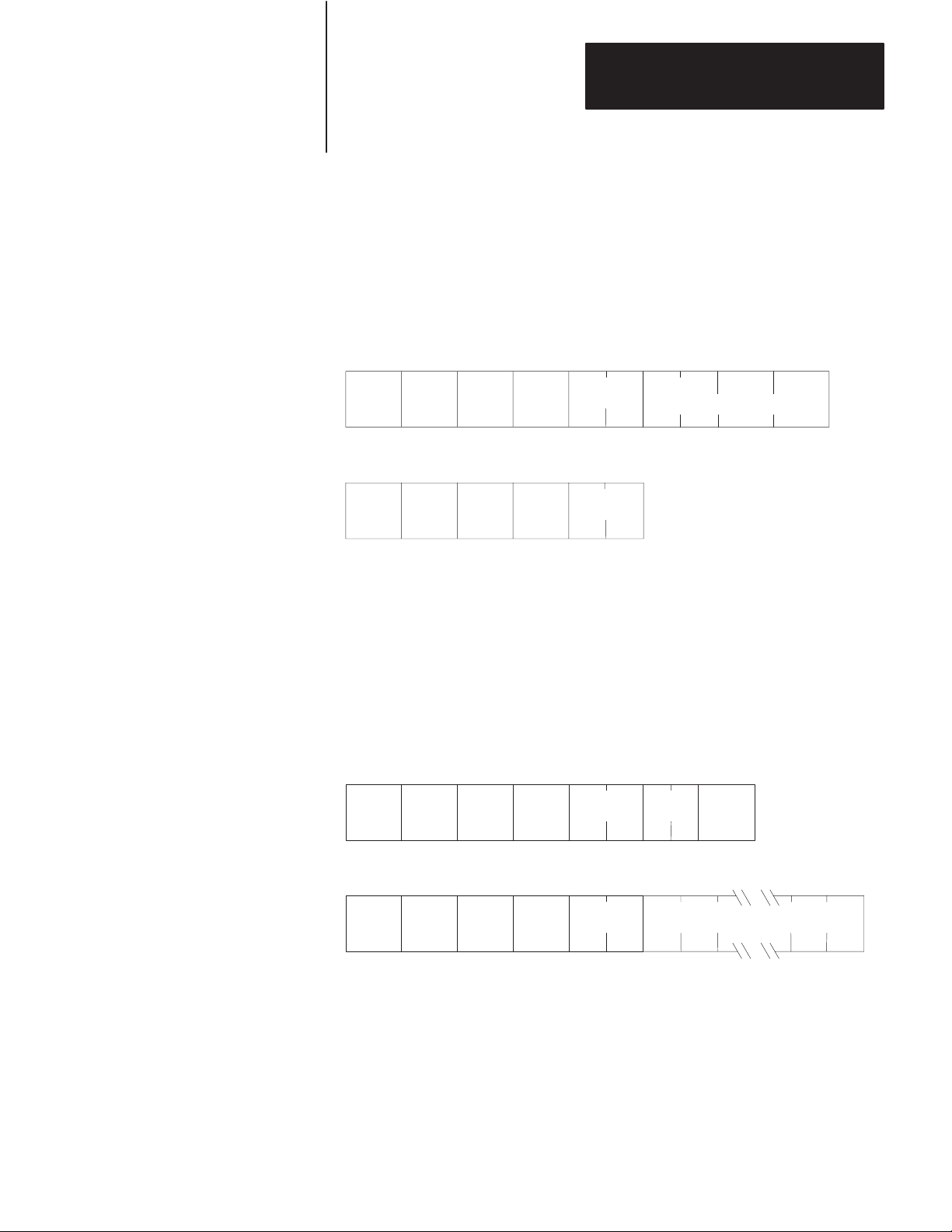
Chapter 5
Message Packet Formats
Note that the interface module at the receiving PC station executes this
command by first making a copy of the addressed PC byte. It then sets or
resets the appropriate bits and writes the byte back into PC memory. At
the same time, the PC processor can be changing the states of the original
bits in memory. Because of this, some data bits may unintentionally be
overwritten.
Command
Reply Format:
Format:
SRCDST
SRCDST
05
45
TNSSTSCMD
TNSSTSCMD
ADDR
Up to 60 Masks of
SET RESET
This Form
Unprotected Read
This command reads words of data from any area of PC data table
memory. Use the SIZE field to specify the number of bytes to be read.
To specify a number of PC words, SIZE should be an even value because
PC words are two bytes long.
Command
Format:
SRCDST
Reply Format:
SRCDST
01
41
TNSSTSCMD
TNSSTSCMD
ADDR
DATA
SIZE
— Max. of 244 Bytes
5-21
 Loading...