

Page 1
Allen-Bradley
MicroLogixt 1000
with Hand-Held
User
Programmer (HHP)
(Cat. No. 1761-HHP-B30)
Manual
Page 2

Important User Information
Because of the variety of uses for the products described in this
publication, those responsible for the application and use of this
control equipment must satisfy themselves that all necessary steps
have been taken to assure that each application and use meets all
performance and safety requirements, including any applicable laws,
regulations, codes and standards.
The illustrations, charts, sample programs and layout examples
shown in this guide are intended solely for purposes of example.
Since there are many variables and requirements associated with any
particular installation, Allen-Bradley does not assume responsibility
or liability (to include intellectual property liability) for actual use
based upon the examples shown in this publication.
Allen-Bradley publication SGI-1.1, Safety Guidelines for the
Application, Installation, and Maintenance of Solid-State Control
(available from your local Allen-Bradley office), describes some
important differences between solid-state equipment and
electromechanical devices that should be taken into consideration
when applying products such as those described in this publication.
Reproduction of the contents of this copyrighted publication, in
whole or in part, without written permission of Allen-Bradley
Company, Inc., is prohibited.
Throughout this manual we use notes to make you aware of safety
considerations:
ATTENTION: Identifies information about practices
or circumstances that can lead to personal injury or
!
Attention statements help you to:
death, property damage or economic loss.
• identify a hazard
• avoid the hazard
• recognize the consequences
Important: Identifies information that is critical for successful
application and understanding of the product.
SLC 500 and MicroLogix are trademarks of Rockwell Automation.
Page 3

Preface
Preface
Read this preface to familiarize yourself with the rest of the manual. This
preface covers the following topics:
• who should use this manual
• the purpose of this manual
• how to use this manual
• conventions used in this manual
• Allen-Bradley support
Who
Should Use this Manual
Purpose of this Manual
Use this manual if you are responsible for designing, installing,
programming, or troubleshooting control systems that use Allen-Bradley
micro controllers.
You should have a basic understanding of electrical circuitry and familiarity
with relay logic. If you do not, obtain the proper training before using this
product.
This manual is a reference guide for the MicroLogix 1000 Programmable
Controller with a MicroLogix 1000 Hand-Held Programmer (HHP). It
describes the procedures you use to install, wire, and program your micro
controller. This manual:
• gives you an overview of the micro controller system
• provides a quick start chapter for beginners
• describes how to use the Hand-Held Programmer
• guides you through how to interpret the instruction set
• contains application examples to show the instruction set in use
If you are using programming software with your MicroLogix 1000
Programmable Controller, see page P–4 for related publications.
P–1
Page 4

Preface
Programmi
Programmi
Contents
Tab Chapter Title Contents
Installing 2 Wiring Your Controller Provides wiring guidelines and diagrams.
ng
ng
of this Manual
Preface
1 Installing Your Controller
3 Connecting the System
Using Y
4
5 Quick Start for New Users
6 Programming Overview
7 Using Analog
8 Using Basic Instructions
9
10 Using Math Instructions
11
our Hand-Held
Programmer
Using Comparison
Instructions
Using Data Handling
Instructions
Describes the purpose, background, and scope of this
manual. Also specifies the audience for whom this
manual is intended.
Provides controller installation procedures and system
safety considerations.
Gives information on wiring your controller system for the
DF1 protocol or DH-485 network.
Describes how to power-up and use your MicroLogix 1000
Hand-Held Programmer (HHP). Also explains how to
install the HHPs memory module.
Provides step-by-step instructions on how to enter a
program, edit it, and then monitor it.
Provides an overview of principles of machine control, a
section on file organization and addressing, and a
program development model.
Provides information on I/O image file format, I/O
configuration, input filter and update times and conversion
of analog data.
Describes how to use the instructions for relay
replacement functions, counting, and timing.
Describes how to use the instructions to compare values
of data in your logic program.
Describes how to use the instructions that perform basic
math functions.
Describes how to perform data handling instructions,
including move and logical instructions and FIFO and
LIFO instructions.
P–2
12
13
14
15
Using Program Flow
Control Instructions
Using Application Specific
Instructions
Using High-Speed
Counter Instructions
Using Communication
Protocols
Describes the instructions that affect program flow and
execution.
Describes the bit shift, sequencer and STI related
instructions.
Describes the four modes of the high-speed counter
instruction and its related instructions.
Provides a general overview of the types of
communication, and explains how to establish network
communication using the message instruction.
Page 5

Tab ContentsTitleChapter
Programmi
16
Instruction List
Programming
Preface
Provides examples to teach you Instruction List
programming and describes programming considerations.
17
ng
18
19 Common Procedures
Troubleshooting 20
Appendix A
Appendix B Programming Reference
Reference
Appendix C
Appendix D
Reference Appendix E Application Programs
Reference Appendix F
Entering and Editing Your
Program
After You’ve Entered Your
Program
Troubleshooting Your
System
Hardware Reference
Valid Addressing Modes
and File T
Instruction Parameters
Understanding the
Communication Protocols
Optional Analog Input
Software Calibration
Glossary
ypes for
Describes the various editing functions you can use with
your program, including search, overwrite, and delete.
Describes how to configure, run, and monitor your
program.
Describes how to perform additional procedures using the
HHP menu.
Explains how to interpret and correct problems with your
micro controller system.
Provides physical, electrical, environmental, and
functional specifications.
Explains the system status file, lists the HHP function
codes, and provides instruction execution times.
Provides a listing of the instructions along with their
parameters and valid file types.
Contains descriptions of the DF1 protocol and DH-485
network.
Provides advanced application examples for the
high-speed counter
Explains how to calibrate your controller using software
offsets.
Contains definitions for terms and abbreviations that are
specific to this product.
, sequencer
, and bit shift instructions.
For More Information
As part of our effort to preserve, protect, and improve our environment,
Allen-Bradley is reducing the amount of paper we use. Less paper means
more options for you. In addition to traditional printed publications and
CD-ROM versions, we now offer on-line manuals with the most up-to-date
information you can get. We recommend that you read the related
publications listed on the next page before starting up your control system.
P–3
Page 6

Preface
Informati
iri
MicroLogix 1000
Informati
iri
MicroLogix 1000
Related Publications
For Read this Document Document Number
A description on how to install and use your MicroLogix 1000
Programmable Controllers. This manual also contains status file
data and instruction set information
MicroLogix 1000 Programmable
Controllers User Manual
1761-6.3
A reference manual that contains the status file data and the
instruction set information for the SLC 500 processors and
MicroLogix 1000 controllers
on on mounting and w
on on mounting and w
controllers, including a mounting template for easy installation
The procedures necessary to install and connect the AIC+ and
DNI
A description on how to install and connect an AIC+. This
manual also contains information on network wiring.
Information on how to install, configure, and commission a DNI DeviceNet Interface User Manual 1761-6.5
In-depth information on grounding and wiring Allen-Bradley
programmable controllers
ng the
ng the
SLC 500 and MicroLogix 1000
Instruction Set Reference Manual
MicroLogix 1000 Programmable
Controllers Installation Instructions
MicroLogix 1000 (Analog) Programmable
Controllers Installation Instructions
Advanced Interface Converter (AIC+) and
DeviceNet Interface (DNI) Installation
Instructions
Advanced Interface Converter (AIC+) User
Manual
Allen-Bradley Programmable Controller
Grounding and Wiring Guidelines
1747-6.15
1761-5.1.2
1761-5.1.3
1761-5.11
1761-6.4
1770-4.1
How to Get More Information
For Obtain Information By
Fast access to
related
publications
•V isiting the MicroLogix internet site http://www.abmicrologix.com — Electronic versions of our
manuals are available for you to search and down load.
•Calling local Allen-Bradley distributor.
P–4
Publications in
printed or
CD
-ROM format
Multiple copies of
a manual
Manuals in other
languages
Ordering a manual or CD-ROM using one of the following methods:
•Fill out and return the User Manual Request Card that was shipped with the unit.
•V isiting the Automation Bookstore at http://www.theautomationbookstore.com
•V isiting the Automation Bookstore at http://www.theautomationbookstore.com
Adding a 2-letter suffix to the end of the publication number when ordering.
•French – FR •German – DE •Italian – IT •Spanish – ES •Portuguese – PT (DNI only)
Page 7
Related Documentation
P
The following documents contain additional information concerning
Allen-Bradley products. To obtain a copy, contact your local Allen-Bradley
office or distributor.
For Read This Document Document Number
A description of important differences
between solid-state programmable
controller products and hard-wired
electromechanical devices
Application Considerations for
Solid-State Controls
Preface
SGI-1.1
An article on wire sizes and types for
grounding electrical equipment
A complete listing of current
documentation, including ordering
instructions. Also indicates whether the
documents are available on CD-ROM or
in multi-languages.
A glossary of industrial automation terms
and abbreviations
Common Techniques Used in this Manual
National Electrical Code
Allen-Bradley Publication Index SD499
Allen-Bradley Industrial Automation
Glossary
Published by the National Fire Protection
Association of Boston, MA.
AG-7.1
The following conventions are used throughout this manual:
• Bulleted lists such as this one provide information, not procedural steps.
• Numbered lists provide sequential steps or hierarchical information.
• Italic type is used for emphasis.
• Text in this font indicates words that appear on the HHP display.
NEW
•
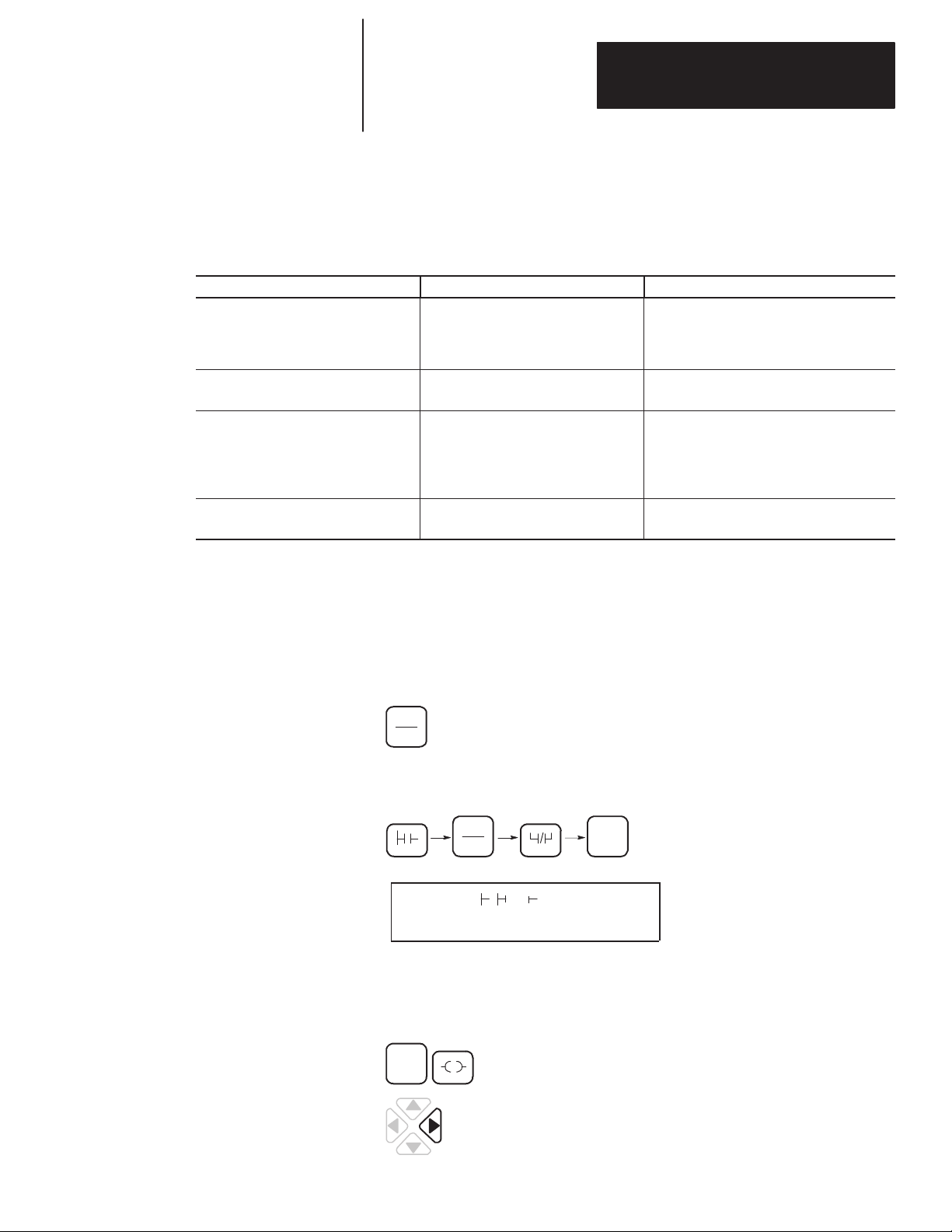
RUNG
Keypad icons, like the one at the left, match the key you
T
should press.
• For operations that require you to press a sequence of keys, the keypad
icons are displayed horizontally on the page, with the resulting screen
shown beneath. For example:
LD
MENU
7
I
ENT
6
0 0 0
I/6 0
• If a character is flashing on the HHP display, it is shown unbolded (such
as the P in the screen above).
• For operations that require you to press two keys simultaneously, the
keypad icons are displayed side-by-side as shown here:
ESC
•
1
For operations that require you to press an arrow key, the
key you should press is shown bolded, such as the right
arrow key shown here.
P–5
Page 8

Preface
Allen-Bradley
Support
Allen-Bradley offers support services worldwide, with over 75 Sales/Support
Offices, 512 authorized Distributors and 260 authorized Systems Integrators
located throughout the United States alone, plus Allen-Bradley
representatives in every major country in the world.
Local
Product Support
Contact your local Allen-Bradley representative for:
• sales and order support
• product technical training
• warranty support
• support service agreements
Technical Product Assistance
If you need to contact Allen-Bradley for technical assistance, please review
the information in the Troubleshooting chapter first. Then call your local
Allen-Bradley representative.
Your Questions or Comments on this Manual
If you find a problem with this manual, please notify us of it on the enclosed
Publication Problem Report.
If you have any suggestions for how this manual could be made more useful
to you, please contact us at the address below:
Allen-Bradley Company, Inc.
Control and Information Group
Technical Communication, Dept. 602V, T122
P.O. Box 2086
Milwaukee, WI 53201-2086
or visit our internet page at:
http://www.abmicrologix.com
P–6
Page 9

T
able of Contents
MicroLogix
(HHP) User Manual
1000 with Hand–Held Programmer
Preface
Who
Should Use this Manual
Purpose
Common
Allen-Bradley Support P–6. . . . . . . . . . . . . . . . . . . . . . . . . . . . . . . . . . . . . . . .
of this Manual
T
echniques Used in this Manual
Hardware
P–1. . . . . . . . . . . . . . . . . . . . . . . . . . . . . . . . . . .
P–1. . . . . . . . . . . . . . . . . . . . . . . . . . . . . . . . . . . . . . . .
P–5. . . . . . . . . . . . . . . . . . . . . . . . . .
Installing Y
W
iring Y
our Controller
our Controller
Chapter
Compliance
Hardware Overview 1–2. . . . . . . . . . . . . . . . . . . . . . . . . . . . . . . . . . . . . . . . . .
Master
Using Surge Suppressors 1–7. . . . . . . . . . . . . . . . . . . . . . . . . . . . . . . . . . . . . .
Safety Considerations 1–9. . . . . . . . . . . . . . . . . . . . . . . . . . . . . . . . . . . . . . . .
Power Considerations 1–10. . . . . . . . . . . . . . . . . . . . . . . . . . . . . . . . . . . . . . . .
Preventing Excessive Heat 1–11. . . . . . . . . . . . . . . . . . . . . . . . . . . . . . . . . . . . .
Controller Spacing 1–12. . . . . . . . . . . . . . . . . . . . . . . . . . . . . . . . . . . . . . . . . . .
Mounting
Chapter
Grounding
Sinking and Sourcing Circuits 2–2. . . . . . . . . . . . . . . . . . . . . . . . . . . . . . . . . . .
Wiring Recommendations 2–3. . . . . . . . . . . . . . . . . . . . . . . . . . . . . . . . . . . . . .
Wiring
Minimizing
Grounding
Wiring
Analog
Wiring
1
to European Union Directives
Control Relay
the Controller
2
Guidelines
Diagrams, Discrete Input and Output V
Electrical Noise on Analog Controllers
Y
our Analog Cable 2–20. . . . . . . . . . . . . . . . . . . . . . . . . . . . . . . . . . .
Y
our Analog Channels 2–21. . . . . . . . . . . . . . . . . . . . . . . . . . . . . . . . . . .
V
oltage and Current Input and Output Ranges
Y
our Controller for High-Speed Counter Applications 2–23. . . . . . . . . . . . .
oltage Ranges 2–6. . . . . . . . . . . . .
1–1. . . . . . . . . . . . . . . . . . . . . . . . . .
1–3. . . . . . . . . . . . . . . . . . . . . . . . . . . . . . . . . . . . . . . . .
1–12. . . . . . . . . . . . . . . . . . . . . . . . . . . . . . . . . . . . . . .
2–1. . . . . . . . . . . . . . . . . . . . . . . . . . . . . . . . . . . . . . . .
2–20. . . . . . . . . . . . . . . . . . . . .
2–22. . . . . . . . . . . . . . . . .
Connecting the System
Chapter
Connecting
Connecting
Connecting
Establishing
DeviceNet
3
the HHP
to a DH-485 Network
the AIC+
Communication
Communications
3–1. . . . . . . . . . . . . . . . . . . . . . . . . . . . . . . . . . . . . . . . .
3–3. . . . . . . . . . . . . . . . . . . . . . . . . . . . . . . .
3–6. . . . . . . . . . . . . . . . . . . . . . . . . . . . . . . . . . . . . . . . .
3–12. . . . . . . . . . . . . . . . . . . . . . . . . . . . . . . . . . . .
3–13. . . . . . . . . . . . . . . . . . . . . . . . . . . . . . . . . . . .
toc–i
Page 10

T
able of Contents
MicroLogix
(HHP) User Manual
1000 with Hand–Held Programmer
Programming
Using Y
our Hand-Held
Programmer
Quick Start for New Users
Programming Overview
Chapter
About Your HHP 4–1. . . . . . . . . . . . . . . . . . . . . . . . . . . . . . . . . . . . . . . . . . . .
Installing
The
Identifying the Power-Up Sequence 4–6. . . . . . . . . . . . . . . . . . . . . . . . . . . . . . .
Understanding
Changing
Chapter
What
Preparing
Entering and Running the Program 5–4. . . . . . . . . . . . . . . . . . . . . . . . . . . . . . .
Monitoring
What
Chapter
Principles
Understanding
Understanding How Programs are Stored and Accessed 6–5. . . . . . . . . . . . . . .
Addressing
Applying
Developing
4
the Optional Memory Module
Keys Y
ou Use 4–4. . . . . . . . . . . . . . . . . . . . . . . . . . . . . . . . . . . . . . . . . . .
the HHPs Functional Areas
the HHPs Defaults
5
to Do First
to Enter a New Program
Operation
to Do Next
6
of Machine Control
File Organization
Data Files
Logic to Y
Y
our Schematics 6–11. . . . . . . . . . . . . . . . . . . . . . . . . . . . . . .
our Logic Program – A Model 6–17. . . . . . . . . . . . . . . . . . . . . . . . .
4–3. . . . . . . . . . . . . . . . . . . . . . . . . . . .
4–7. . . . . . . . . . . . . . . . . . . . . . . . .
4–17. . . . . . . . . . . . . . . . . . . . . . . . . . . . . . . . . . .
5–1. . . . . . . . . . . . . . . . . . . . . . . . . . . . . . . . . . . . . . . . . . . .
5–2. . . . . . . . . . . . . . . . . . . . . . . . . . . . . . .
5–9. . . . . . . . . . . . . . . . . . . . . . . . . . . . . . . . . . . . . . . . .
5–12. . . . . . . . . . . . . . . . . . . . . . . . . . . . . . . . . . . . . . . . . . . .
6–1. . . . . . . . . . . . . . . . . . . . . . . . . . . . . . . . . . .
6–3. . . . . . . . . . . . . . . . . . . . . . . . . . . . . . . . .
6–7. . . . . . . . . . . . . . . . . . . . . . . . . . . . . . . . . . . . . . . .
Using Analog
Using Basic Instructions
toc–ii
Chapter
I/O
I/O
Input
Converting
Chapter
About
Bit Instructions Overview 8–3. . . . . . . . . . . . . . . . . . . . . . . . . . . . . . . . . . . . . .
Load (LD), And (AND), and Or (OR) 8–3. . . . . . . . . . . . . . . . . . . . . . . . . . . . . .
Load
Load
One-Shot
7
Image
Configuration
Filter and Update T
Analog Data
imes 7–2. . . . . . . . . . . . . . . . . . . . . . . . . . . . . . . . . . .
8
Basic Instructions
Inverted (LDI), And Inverted (ANI), and Or Inverted (ORI)
T
rue (LDT) and Or True (ORT) 8–6. . . . . . . . . . . . . . . . . . . . . . . . . . . . . .
Rising (OSR)
7–1. . . . . . . . . . . . . . . . . . . . . . . . . . . . . . . . . . . . . . . . . . . . . . . . .
7–2. . . . . . . . . . . . . . . . . . . . . . . . . . . . . . . . . . . . . . . . . . . .
7–4. . . . . . . . . . . . . . . . . . . . . . . . . . . . . . . . . . . . . . .
8–2. . . . . . . . . . . . . . . . . . . . . . . . . . . . . . . . . . . . . . .
8–4. . . . . . . . . . .
8–7. . . . . . . . . . . . . . . . . . . . . . . . . . . . . . . . . . . . . . .
Page 11

T
able of Contents
MicroLogix
(HHP) User Manual
Output (OUT) 8–8. . . . . . . . . . . . . . . . . . . . . . . . . . . . . . . . . . . . . . . . . . . . . .
Set (SET) and Reset (RST) 8–8. . . . . . . . . . . . . . . . . . . . . . . . . . . . . . . . . . . .
Branch Instructions Overview 8–9. . . . . . . . . . . . . . . . . . . . . . . . . . . . . . . . . . .
Memory Push (MPS), Memory Read (MRD), and Memory Pop (MPP) 8–10. . . . . .
And Block (ANB) and Or Block (ORB) 8–12. . . . . . . . . . . . . . . . . . . . . . . . . . . . .
Timer Instructions Overview 8–14. . . . . . . . . . . . . . . . . . . . . . . . . . . . . . . . . . . .
Timer On-Delay (TON) 8–16. . . . . . . . . . . . . . . . . . . . . . . . . . . . . . . . . . . . . . . .
Of
Timer
Retentive
Counter Instructions Overview 8–21. . . . . . . . . . . . . . . . . . . . . . . . . . . . . . . . . .
Count Up (CTU) 8–24. . . . . . . . . . . . . . . . . . . . . . . . . . . . . . . . . . . . . . . . . . . .
Count Down (CTD) 8–25. . . . . . . . . . . . . . . . . . . . . . . . . . . . . . . . . . . . . . . . . .
Reset (RES) 8–27. . . . . . . . . . . . . . . . . . . . . . . . . . . . . . . . . . . . . . . . . . . . . . .
Basic
f-Delay (TOF) 8–18. . . . . . . . . . . . . . . . . . . . . . . . . . . . . . . . . . . . . . . .
T
imer (RTO) 8–20. . . . . . . . . . . . . . . . . . . . . . . . . . . . . . . . . . . . . . . .
Instructions in the Paper Drilling Machine Application Example
1000 with Hand–Held Programmer
8–28. . . . . . .
Using Comparison
Instructions
Using Math Instructions
Chapter
About
Comparison Instructions Overview 9–2. . . . . . . . . . . . . . . . . . . . . . . . . . . . . . .
Equal (EQU) 9–3. . . . . . . . . . . . . . . . . . . . . . . . . . . . . . . . . . . . . . . . . . . . . . .
Not Equal (NEQ) 9–4. . . . . . . . . . . . . . . . . . . . . . . . . . . . . . . . . . . . . . . . . . . .
Less Than (LES) 9–5. . . . . . . . . . . . . . . . . . . . . . . . . . . . . . . . . . . . . . . . . . . .
Less Than or Equal (LEQ) 9–6. . . . . . . . . . . . . . . . . . . . . . . . . . . . . . . . . . . . .
Greater
Greater Than or Equal (GEQ) 9–8. . . . . . . . . . . . . . . . . . . . . . . . . . . . . . . . . . .
Masked Comparison for Equal (MEQ) 9–9. . . . . . . . . . . . . . . . . . . . . . . . . . . . .
Limit
Comparison
9
the Comparison Instructions
Than (GR
T
est (LIM) 9–10. . . . . . . . . . . . . . . . . . . . . . . . . . . . . . . . . . . . . . . . . . . . .
T) 9–7. . . . . . . . . . . . . . . . . . . . . . . . . . . . . . . . . . . . . . . . . .
Instructions in the Paper Drilling Machine Application Example
Chapter 10
About
the Math Instructions
Math Instructions Overview 10–2. . . . . . . . . . . . . . . . . . . . . . . . . . . . . . . . . . . .
Add (ADD) 10–4. . . . . . . . . . . . . . . . . . . . . . . . . . . . . . . . . . . . . . . . . . . . . . . .
Subtract (SUB) 10–5. . . . . . . . . . . . . . . . . . . . . . . . . . . . . . . . . . . . . . . . . . . . .
Addition and Subtraction
32-Bit
Multiply (MUL) 10–8. . . . . . . . . . . . . . . . . . . . . . . . . . . . . . . . . . . . . . . . . . . . . .
Divide (DIV) 10–9. . . . . . . . . . . . . . . . . . . . . . . . . . . . . . . . . . . . . . . . . . . . . . .
Divide (DDV)
Double
Clear (CLR) 10–11. . . . . . . . . . . . . . . . . . . . . . . . . . . . . . . . . . . . . . . . . . . . . . . .
Square
Root (SQR)
Scale Data (SCL) 10–12. . . . . . . . . . . . . . . . . . . . . . . . . . . . . . . . . . . . . . . . . . . .
Instructions in the Paper Drilling Machine Application Example
Math
9–2. . . . . . . . . . . . . . . . . . . . . . . . . . . . . . .
9–12. .
10–1. . . . . . . . . . . . . . . . . . . . . . . . . . . . . . . . . . . .
10–6. . . . . . . . . . . . . . . . . . . . . . . . . . . . . . . . . .
10–10. . . . . . . . . . . . . . . . . . . . . . . . . . . . . . . . . . . . . . . . .
10–11. . . . . . . . . . . . . . . . . . . . . . . . . . . . . . . . . . . . . . . . . .
10–15. . . . . . .
toc–iii
Page 12

T
able of Contents
MicroLogix
(HHP) User Manual
1000 with Hand–Held Programmer
Using Data Handling
Instructions
Chapter 11
About
the Data Handling Instructions
Convert
Convert
Decode
Encode
Copy
Move and Logical Instructions Overview 11–13. . . . . . . . . . . . . . . . . . . . . . . . . . .
Move (MOV) 11–15. . . . . . . . . . . . . . . . . . . . . . . . . . . . . . . . . . . . . . . . . . . . . . .
Masked Move (MVM) 11–16. . . . . . . . . . . . . . . . . . . . . . . . . . . . . . . . . . . . . . . . .
And (AND) 11–18. . . . . . . . . . . . . . . . . . . . . . . . . . . . . . . . . . . . . . . . . . . . . . . .
Or (OR) 11–19. . . . . . . . . . . . . . . . . . . . . . . . . . . . . . . . . . . . . . . . . . . . . . . . . .
Exclusive Or (XOR) 11–20. . . . . . . . . . . . . . . . . . . . . . . . . . . . . . . . . . . . . . . . . .
Not (NOT) 11–21. . . . . . . . . . . . . . . . . . . . . . . . . . . . . . . . . . . . . . . . . . . . . . . . .
Negate (NEG) 11–22. . . . . . . . . . . . . . . . . . . . . . . . . . . . . . . . . . . . . . . . . . . . . .
FIFO
FIFO Load (FFL) and FIFO Unload (FFU) 11–25. . . . . . . . . . . . . . . . . . . . . . . . . .
LIFO Load (LFL) and LIFO Unload (LFU) 11–28. . . . . . . . . . . . . . . . . . . . . . . . . . .
Data
to BCD (T
from BCD (FRD)
4 to 1 of 16 (DCD)
1 of 16 to 4 (ENC)
File (COP) and Fill File (FLL) Instructions
and LIFO Instructions Overview
Handling Instructions in the Paper Drilling Machin
Application Example
OD) 11–2. . . . . . . . . . . . . . . . . . . . . . . . . . . . . . . . . . . . . . . .
11–2. . . . . . . . . . . . . . . . . . . . . . . . . . . . . .
11–3. . . . . . . . . . . . . . . . . . . . . . . . . . . . . . . . . . . . . .
11–7. . . . . . . . . . . . . . . . . . . . . . . . . . . . . . . . . . . . .
11–8. . . . . . . . . . . . . . . . . . . . . . . . . . . . . . . . . . . . .
11–10. . . . . . . . . . . . . . . . . . . . . .
11–23. . . . . . . . . . . . . . . . . . . . . . . . . . . . .
11–31. . . . . . . . . . . . . . . . . . . . . . . . . . . . . . . . . . . . . . .
Using Program Flow Control
Instructions
Using Application Specific
Instructions
Chapter 12
About
the Program Flow Control Instructions
Jump (JMP) and Label (LBL) 12–2. . . . . . . . . . . . . . . . . . . . . . . . . . . . . . . . . . .
Jump to Subroutine (JSR), Subroutine (SBR), and Return (RET) 12–3. . . . . . . . . .
Control Reset (MCR)
Master
Temporary End (TND) 12–7. . . . . . . . . . . . . . . . . . . . . . . . . . . . . . . . . . . . . . . .
Suspend (SUS) 12–7. . . . . . . . . . . . . . . . . . . . . . . . . . . . . . . . . . . . . . . . . . . . .
Immediate
Immediate
Program
Input with Mask (IIM)
Output with Mask (IOM)
Flow Control Instructions in the Paper Drilling Machine
Application Example
Chapter 13
About
the Application Specific Instructions
Shift Instructions Overview
Bit
Shift Left (BSL)
Bit
Shift Right (BSR)
Bit
Sequencer Instructions Overview 13–6. . . . . . . . . . . . . . . . . . . . . . . . . . . . . . . .
Sequencer Output (SQO) and Sequencer Compare (SQC) 13–6. . . . . . . . . . . . . .
Sequencer Load (SQL) 13–12. . . . . . . . . . . . . . . . . . . . . . . . . . . . . . . . . . . . . . .
T
Selectable
imed Interrupt (STI) Function Overview 13–15. . . . . . . . . . . . . . . . . . .
12–1. . . . . . . . . . . . . . . . . . . . . . . .
12–6. . . . . . . . . . . . . . . . . . . . . . . . . . . . . . . . . . .
12–8. . . . . . . . . . . . . . . . . . . . . . . . . . . . . . . . .
12–9. . . . . . . . . . . . . . . . . . . . . . . . . . . . . . .
12–10. . . . . . . . . . . . . . . . . . . . . . . . . . . . . . . . . . . . . . .
13–1. . . . . . . . . . . . . . . . . . . . . . . . . .
13–2. . . . . . . . . . . . . . . . . . . . . . . . . . . . . . . . . .
13–3. . . . . . . . . . . . . . . . . . . . . . . . . . . . . . . . . . . . . . . . . .
13–4. . . . . . . . . . . . . . . . . . . . . . . . . . . . . . . . . . . . . . . . .
toc–iv
Page 13

T
able of Contents
MicroLogix
(HHP) User Manual
Selectable Timed Disable (STD) and Enable (STE) 13–17. . . . . . . . . . . . . . . . . . .
T
Selectable
Interrupt Subroutine (INT) 13–19. . . . . . . . . . . . . . . . . . . . . . . . . . . . . . . . . . . . . .
Application
Application Example
imed Start (STS)
Specific Instructions in the Paper Drilling Machine
1000 with Hand–Held Programmer
13–18. . . . . . . . . . . . . . . . . . . . . . . . . . . . . . . . . . .
13–20. . . . . . . . . . . . . . . . . . . . . . . . . . . . . . . . . . . . . . .
Using High–Speed Counter
Instructions
Using Communication
Protocols
Chapter 14
About the High-Speed Counter Instructions 14–1. . . . . . . . . . . . . . . . . . . . . . . . .
High-Speed Counter Instructions Overview 14–2. . . . . . . . . . . . . . . . . . . . . . . . .
High-Speed Counter (HSC) 14–4. . . . . . . . . . . . . . . . . . . . . . . . . . . . . . . . . . . .
High-Speed Counter Load (HSL) 14–15. . . . . . . . . . . . . . . . . . . . . . . . . . . . . . . . .
High-Speed Counter Reset (RES) 14–19. . . . . . . . . . . . . . . . . . . . . . . . . . . . . . . .
High-Speed Counter Reset Accumulator (RAC) 14–20. . . . . . . . . . . . . . . . . . . . . .
High-Speed Counter Interrupt Enable (HSE) and Disable (HSD) 14–21. . . . . . . . . .
Update High-Speed Counter Image Accumulator (OUT) 14–23. . . . . . . . . . . . . . . .
Happens to the HSC When Going to RRUN Mode
What
High-Speed
Application Example
Counter Instructions in the Paper Drilling Machine
Chapter 15
Types
of Communication
Message
Timing
MSG Instruction Error Codes 15–11. . . . . . . . . . . . . . . . . . . . . . . . . . . . . . . . . . .
Application
Instruction (MSG)
Diagram for a Successful MSG Instruction
Examples that Use the MSG Instruction
14–23. . . . . . . . . . . . . . . .
14–28. . . . . . . . . . . . . . . . . . . . . . . . . . . . . . . . . . . . . . .
15–1. . . . . . . . . . . . . . . . . . . . . . . . . . . . . . . . . . . . . .
15–2. . . . . . . . . . . . . . . . . . . . . . . . . . . . . . . . . . . .
15–9. . . . . . . . . . . . . . . . . . . .
15–12. . . . . . . . . . . . . . . . . . .
Instruction List Programming
Concepts
Entering and Editing Y
our
Program
Chapter 16
Programming
Programming Considerations 16–8. . . . . . . . . . . . . . . . . . . . . . . . . . . . . . . . . . .
Examples
Chapter 17
Entering
Editing Considerations 17–3. . . . . . . . . . . . . . . . . . . . . . . . . . . . . . . . . . . . . . . .
Editing Modes 17–3. . . . . . . . . . . . . . . . . . . . . . . . . . . . . . . . . . . . . . . . . . . . . .
Deleting Instructions and Rungs 17–6. . . . . . . . . . . . . . . . . . . . . . . . . . . . . . . . .
Searching for Specific Addresses 17–8. . . . . . . . . . . . . . . . . . . . . . . . . . . . . . . .
the Program Monitor
16–1. . . . . . . . . . . . . . . . . . . . . . . . . . . . . . . . . . . . . . .
17–1. . . . . . . . . . . . . . . . . . . . . . . . . . . . . . . . . . .
toc–v
Page 14

T
able of Contents
MicroLogix
(HHP) User Manual
1000 with Hand–Held Programmer
After You’ve Entered Your
Program
Common Procedures
Chapter 18
Changing
Accepting
Changing Controller Modes 18–20. . . . . . . . . . . . . . . . . . . . . . . . . . . . . . . . . . . .
Monitoring
Viewing
Using
Forcing
the Program Configuration Defaults
Y
our Program Edits 18–20. . . . . . . . . . . . . . . . . . . . . . . . . . . . . . . . . .
Y
our Controller 18–24. . . . . . . . . . . . . . . . . . . . . . . . . . . . . . . . . . . . .
Data T
able Files
the Multi-Point Function
Inputs and Outputs
Chapter 19
Using
a Memory Module
Clearing
Changing
Changing
a Program from the Micro Controller
the Micro Controller’s Baud Rate
the Micro Controller’s Communication Defaults
Troubleshooting
18–1. . . . . . . . . . . . . . . . . . . . . . .
18–27. . . . . . . . . . . . . . . . . . . . . . . . . . . . . . . . . . . . . .
18–30. . . . . . . . . . . . . . . . . . . . . . . . . . . . . . . . . .
18–34. . . . . . . . . . . . . . . . . . . . . . . . . . . . . . . . . . . . .
19–1. . . . . . . . . . . . . . . . . . . . . . . . . . . . . . . . . . . . . .
19–6. . . . . . . . . . . . . . . . . . . . . . . .
19–6. . . . . . . . . . . . . . . . . . . . . . . . .
19–7. . . . . . . . . . . . . . .
roubleshooting Y
T
our System
Hardware Reference
Chapter 20
Understanding
Identifying HHP Errors 20–3. . . . . . . . . . . . . . . . . . . . . . . . . . . . . . . . . . . . . . . .
the T
Using
Controller Error Recovery Model 20–10. . . . . . . . . . . . . . . . . . . . . . . . . . . . . . . . .
Identifying
Recovering
Calling Allen-Bradley for Assistance 20–16. . . . . . . . . . . . . . . . . . . . . . . . . . . . . .
the Controller LED Status
race Feature 20–8. . . . . . . . . . . . . . . . . . . . . . . . . . . . . . . . . . . . . . .
Controller Faults
Y
our Work 20–16. . . . . . . . . . . . . . . . . . . . . . . . . . . . . . . . . . . . . . . .
Reference
Appendix A
Controller
Controller
Hand-Held Programmer Specifications A–9. . . . . . . . . . . . . . . . . . . . . . . . . . . .
Controller and Hand-Held Programmer Accessories and Replacement Parts A–11.
Specifications
Dimensions
20–1. . . . . . . . . . . . . . . . . . . . . . . . . . .
20–11. . . . . . . . . . . . . . . . . . . . . . . . . . . . . . . . . . . .
A–1. . . . . . . . . . . . . . . . . . . . . . . . . . . . . . . . . . . . . . .
A–7. . . . . . . . . . . . . . . . . . . . . . . . . . . . . . . . . . . . . . . .
toc–vi
Page 15

T
able of Contents
MicroLogix
(HHP) User Manual
1000 with Hand–Held Programmer
Programming Reference
Valid Addressing Modes and
File T
ypes for Instruction
Parameters
Understanding the
Communication Protocols
Application Example
Programs
Appendix B
Controller
Function Codes B–13. . . . . . . . . . . . . . . . . . . . . . . . . . . . . . . . . . . . . . . . . . . . .
Instruction
Status File
Execution T
imes and Memory Usage B–16. . . . . . . . . . . . . . . . . . . . .
Appendix C
Available
Available Addressing Modes C–2. . . . . . . . . . . . . . . . . . . . . . . . . . . . . . . . . . . .
File T
ypes C–1. . . . . . . . . . . . . . . . . . . . . . . . . . . . . . . . . . . . . . . . . .
Appendix D
RS-232
DF1 Full-Duplex Protocol D–2. . . . . . . . . . . . . . . . . . . . . . . . . . . . . . . . . . . . . .
DF1
DH-485
Appendix
Paper
Time Driven Sequencer Application Example E–25. . . . . . . . . . . . . . . . . . . . . . . .
Event Driven Sequencer Application Example E–27. . . . . . . . . . . . . . . . . . . . . . .
Bottle
Communication Interface
Half-Duplex Slave Protocol
Communication Protocol
E
Drilling Machine Application Example
Line Example
B–1. . . . . . . . . . . . . . . . . . . . . . . . . . . . . . . . . . . . . . . . .
D–1. . . . . . . . . . . . . . . . . . . . . . . . . . . . . . . .
D–4. . . . . . . . . . . . . . . . . . . . . . . . . . . . . . . . .
D–9. . . . . . . . . . . . . . . . . . . . . . . . . . . . . . . .
E–2. . . . . . . . . . . . . . . . . . . . . . . . .
E–29. . . . . . . . . . . . . . . . . . . . . . . . . . . . . . . . . . . . . . . . . .
Optional Analog Input
Software Calibration
Appendix
Calibrating
Glossary
F
an Analog Input Channel
F–1. . . . . . . . . . . . . . . . . . . . . . . . . . . . . .
toc–vii
Page 16

Summary of Changes
Summary of Changes
The information below summarizes the changes to this manual since the last
printing as Publication 1761-6.2—October 1997.
To help you find new information and updated information in this release of
the manual, we have included change bars as shown to the right of this
paragraph.
New Information
Updated Information
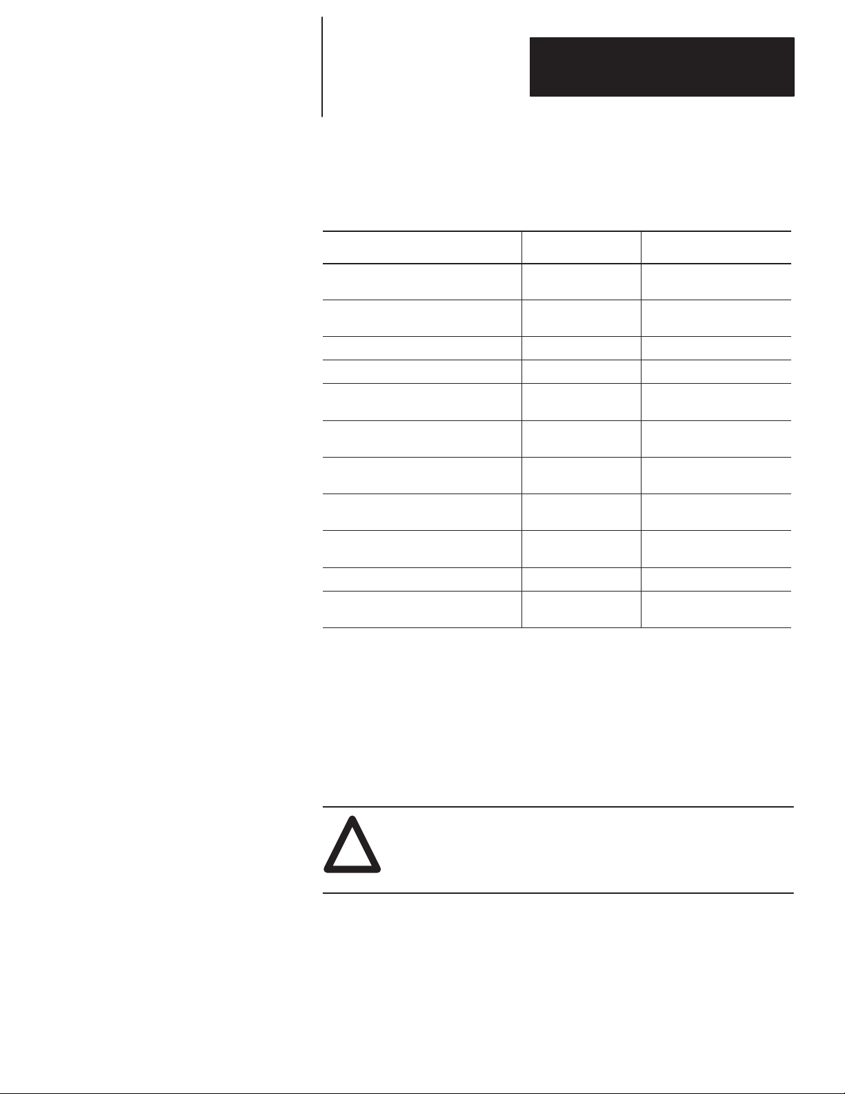
The table below lists sections that document new features and additional
information about existing features, and shows where to find this new
information.
For This New Information See
Power supply inrush
Class I, Division 2 certification pages 1–12, A–2
analog controllers
automatic protocol switching page 3–13
DeviceNet communications page 3–13
software compatibility page 4–1
SCL instruction application example
remote network support
page 1–11
pages 2–17, 7–1, 18–14, appendix A
page 10–14
page D–17
Changes from the previous release of this manual that require you to
reference information differently are as follows:
• The safety considerations for mounting your controller have been
updated; see chapter 1, Installing Your Controller.
• The section on establishing communication has been updated; see chapter
3, Connecting the System.
• For updated information on HHP support and compatibility of the series
functionality of your MicroLogix controller, see chapter 15, Using
Communication Protocols.
• The message timing diagram has been updated; see chapter 15, Using
Communication Protocols.
• The MicroLogix 1000 programmable controllers’ VA ratings and power
supply inrush specifications have been updated; see appendix A,
Hardware Reference.
• The agency certification specifications have been updated; see appendix
A, Hardware Reference.
• The analog output overall accuracy specification has been updated; see
appendix A, Hardware Reference.
• The user interrupt latency information has been updated; see appendix B,
Programming Reference.
• The DF1 Full-Duplex and DH-485 configuration parameters have been
updated; see appendix D, Understanding Communication Protocols.
soc–i
Page 17

Chapter
1
Installing Your Controller
This chapter shows you how to install your MicroLogix 1000 Programmable
Controller. The only tools you require are a Flat head or Phillips head
screwdriver and drill. Topics include:
• compliance to European Union Directives
•
hardware overview
• master control relay
• surge suppressors
• safety considerations
• power considerations
• preventing excessive heat
• controller spacing
• mounting the controller
Compliance to European Union Directives
If this product has the CE mark it is approved for installation within the
European Union and EEA regions. It has been designed and tested to meet
the following directives.
EMC Directive
This product is tested to meet Council Directive 89/336/EEC
Electromagnetic Compatibility (EMC) and the following standards, in whole
or in part, documented in a technical construction file:
• EN 50081-2
EMC – Generic Emission Standard, Part 2 – Industrial Environment
• EN 50082-2
EMC – Generic Immunity Standard, Part 2 – Industrial Environment
This product is intended for use in an industrial environment.
Low V
oltage Directive
This product is tested to meet Council Directive 73/23/EEC Low Voltage, by
applying the safety requirements of EN 61131–2 Programmable Controllers,
Part 2 – Equipment Requirements and Tests.
For specific information required by EN 61131-2, see the appropriate
sections in this publication, as well as the following Allen-Bradley
publications:
• Industrial Automation Wiring and Grounding Guidelines For Noise
Immunity, publication 1770-4.1
• Guidelines for Handling Lithium Batteries, publication AG-5.4
• Automation Systems Catalog, publication B111
1–1
Page 18
Chapter 1
1761-L20
Installing Y
our Controller
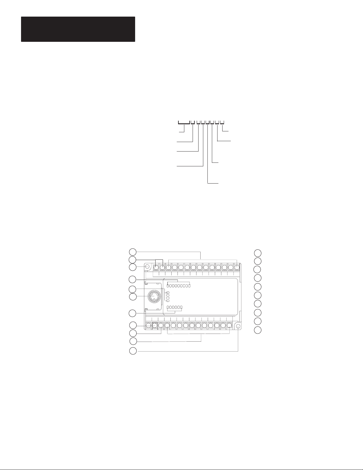
Hardware Overview
The MicroLogix 1000 programmable controller is a packaged controller
containing a power supply, input circuits, output circuits, and a processor.
The controller is available in 10 I/O, 16 I/O and 32 I/O configurations, as
well as an analog version with 20 discrete I/O and 5 analog I/O.
The catalog number for the controller is composed of the following:
AWA-5A
Bulletin Number
Base Unit
Unit I/O Count: 20
Input Signal:
A = 120V ac
B = 24V dc
The hardware features of the controller are:
Analog I/O
Analog Circuits:
Inputs = 4
Outputs = 1
Power Supply:
A = 120/240V ac
B = 24V dc
Output Type:
W = Relay
B = MOSFET
A = Triac
10
1
2
3
4
5
6
7
8
9
3
POWER
RUN
FAULT
FORCE
IN
OUT
1
Input terminals
2
dc output terminals (or not used)
3
Mounting hole
Input LEDs
4
5
Status LEDs
6
RS-232 communication channel
7
Output LEDs
8
Power supply line power
9
Ground screw
Output terminals
10
20142
1–2
Page 19

Chapter 1
Installing Y
our Controller
Master
Control Relay
A hard-wired master control relay (MCR) provides a reliable means for
emergency controller shutdown. Since the master control relay allows the
placement of several emergency-stop switches in different locations, its
installation is important from a safety standpoint. Overtravel limit switches
or mushroom head push buttons are wired in series so that when any of them
opens, the master control relay is de-energized. This removes power to input
and output device circuits. Refer to the figure on page 1–5.
ATTENTION: Never alter these circuits to defeat their function,
since serious injury and/or machine damage could result.
!
Important: If you are using an external dc output power supply, interrupt
the dc output side rather than the ac line side of the supply to
avoid the additional delay of power supply turn-off.
The external ac line of the dc output power supply should be
fused.
Connect a set of master control relays in series with the dc
power supplying the input and output circuits.
Place the main power disconnect switch where operators and maintenance
personnel have quick and easy access to it. If you mount a disconnect switch
inside the controller enclosure, place the switch operating handle on the
outside of the enclosure, so that you can disconnect power without opening
the enclosure.
Whenever any of the emergency-stop switches are opened, power to input
and output devices should be removed.
When you use the master control relay to remove power from the external
I/O circuits, power continues to be provided to the controller’s power supply
so that diagnostic indicators on the processor can still be observed.
The master control relay is not a substitute for a disconnect to the controller.
It is intended for any situation where the operator must quickly de-energize
I/O devices only. When inspecting or installing terminal connections,
replacing output fuses, or working on equipment within the enclosure, use
the disconnect to shut off power to the rest of the system.
Important: Do not control the master control relay with the controller.
Provide the operator with the safety of a direct connection
between an emergency-stop switch and the master control relay.
1–3
Page 20

Chapter 1
Installing Y
our Controller
Using Emergency-Stop Switches
When using emergency-stop switches, adhere to the following points:
• Do not program emergency-stop switches in the controller program. Any
emergency-stop switch should turn off all machine power by turning off
the master control relay.
• Observe all applicable local codes concerning the placement and labeling
of emergency-stop switches.
• Install emergency-stop switches and the master control relay in your
system. Make certain that relay contacts have a sufficient rating for your
application. Emergency-stop switches must be easy to reach.
• In the following illustration, input and output circuits are shown with
MCR protection. However, in most applications, only output circuits
require MCR protection.
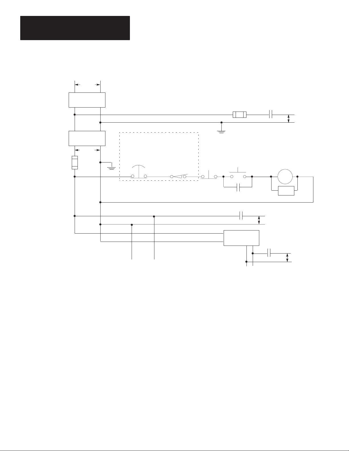
The following illustrations show the Master Control Relay wired in a
grounded system.
Important: The illustrations only show output circuits with MCR
protection. In most applications input circuits do not require
MCR protection; however, if you need to remove power from
all field devices, you must include MCR contacts in series with
input power wiring.
1–4
Page 21
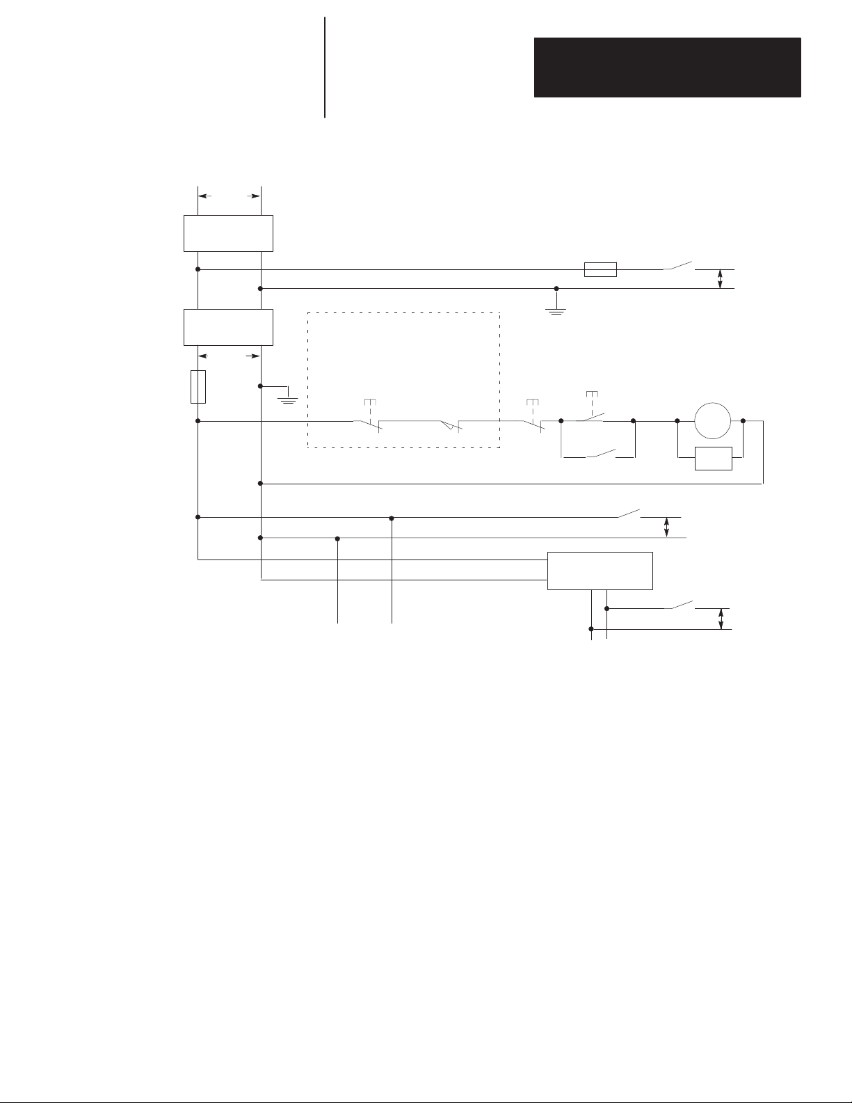
L1 L2
230V ac
Disconnect
Schematic (Using IEC Symbols)
Chapter 1
Installing Y
our Controller
Fuse
MCR
230V ac
I/O Circuits
Isolation
Transformer
230V ac
X1
Fuse
Operation of either of these contacts will
remove power from the adapter external I/O
X2
circuits, stopping machine motion.
Emergency-Stop
Push Button
(Lo) (Hi)
Line Terminals: Connect to 230V ac
terminals of controller Power Supply.
Overtravel
Limit Switch
Stop
Start
MCR
MCR
dc Power Supply.
Use IEC 950/EN 60950
+
—
Line terminals: Connect to 24V dc
terminals of controller Power Supply.
Master Control Relay (MCR)
Cat. No. 700-PK400A1
Suppressor
Cat. No. 700-N24
MCR
Suppr.
230V ac
I/O Circuits
MCR
24V dc
I/O Circuits
1–5
Page 22
Chapter 1
Installing Y
our Controller
L1 L2
230V ac
Disconnect
Schematic (Using ANSI/CSA Symbols)
Fuse
MCR
230V ac
Output
Circuits
Isolation
Transformer
115V ac
X1
Fuse
Operation of either of these contacts will
remove power from the adapter external I/O
X2
circuits, stopping machine motion.
Emergency-Stop
Push Button
(Lo) (Hi)
Line Terminals: Connect to 115V ac
terminals of controller Power Supply.
Overtravel
Limit Switch
Stop
Master Control Relay (MCR)
Cat. No. 700-PK400A1
+
Suppressor
Cat. No. 700-N24
115V ac
Output
Circuits
MCR
Start
MCR
MCR
dc Power Supply.
Use N.E.C. Class 2
for UL Listing.
—
Line terminals: Connect to 24V dc
terminals of controller Power Supply.
MCR
Suppr.
24V dc
Output
Circuits
1–6
Page 23
Chapter 1
Installing Y
our Controller
Using Surge Suppressors
Inductive load devices such as motor starters and solenoids require the use of
some type of surge suppression to protect the controller output contacts.
Switching inductive loads without surge suppression can significantly
reduce
the lifetime of relay contacts. By adding a suppression device directly across
the coil of an inductive device, you will prolong the life of the switch
contacts. You also reduce the effects of voltage transients caused by
interrupting the current to that inductive device, and prevent electrical noise
from radiating into system wiring.
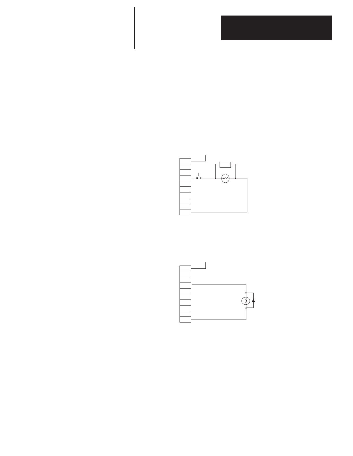
The following diagram shows an output with a suppression device. We
recommend that you locate the suppression device as close as possible to the
load device.
+
dc or L1
ac
or dc
Outputs
VAC/VDC
OUT 0
OUT
OUT 2
OUT 3
OUT
OUT 5
OUT 6
OUT 7
COM
1
4
Snubber
dc COM or L2
If you connect a micro controller FET output to an inductive load, we
recommend that you use a 1N4004 diode for surge suppression, as shown in
the following illustration.
+24V
dc
VAC/VDC
OUT 0
OUT
1
Relay
or Solid State
dc Outputs
OUT 2
OUT 3
OUT
OUT 5
OUT 6
OUT 7
COM
4
24V dc common
1N4004 Diode
1–7
Page 24
Chapter 1
Installing Y
our Controller
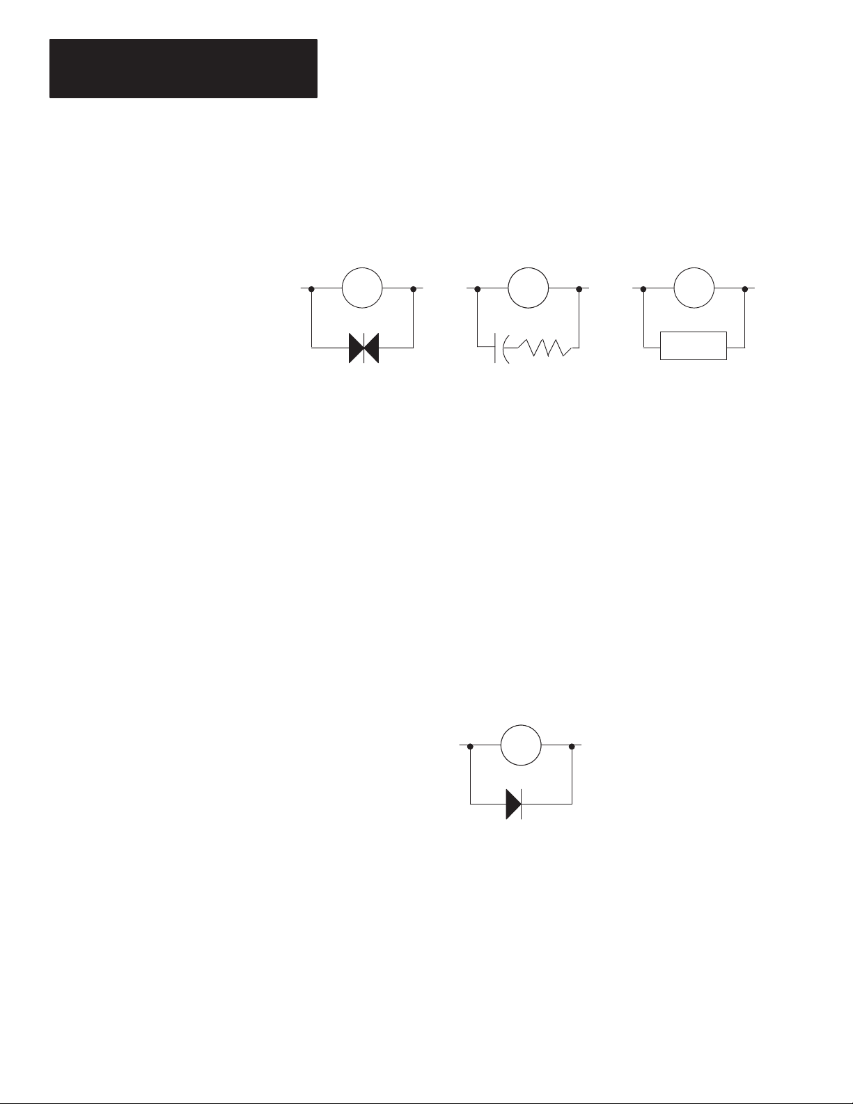
Suitable surge suppression methods for inductive ac load devices include a
varistor, an RC network, or an Allen-Bradley surge suppressor, all shown
below. These components must be appropriately rated to suppress the
switching transient characteristic of the particular inductive device. See the
table on page 1–9 for recommended suppressors.
Surge Suppression for Inductive ac Load Devices
Output Device
Varistor
Output DeviceOutput Device Output Device
Surge
Suppressor
RC Network
If you connect a micro controller triac output to control an inductive load, we
recommend that you use varistors to suppress noise. Choose a varistor that is
appropriate for the application. The suppressors we recommend for triac
outputs when switching 120V ac inductive loads are a Harris MOV, part
number V175 LA10A, or an Allen-Bradley MOV, catalog number 599-K04
or 599-KA04. Consult the varistor manufacturer’s data sheet when selecting
a varistor for your application.
For inductive dc load devices, a diode is suitable. A 1N4004 diode is
acceptable for most applications. A surge suppressor can also be used. See
the table on page 1–9 for recommended suppressors.
As shown in the illustration below, these surge suppression circuits connect
directly across the load device. This reduces arcing of the output contacts.
(High transient can cause arcing that occurs when switching off an inductive
device.)
Surge Suppression for Inductive dc Load Devices
1–8
—
Output DeviceOutput Device
Diode
(A surge suppressor can also be used.)
+
Page 25
Chapter 1
Installing Y
our Controller
Recommended Surge Suppressors
We recommend the Allen-Bradley surge suppressors shown in the following
table for use with Allen-Bradley relays, contactors, and starters.
Device Coil Voltage
Bulletin 509 Motor Starter
Bulletin 509 Motor Starter
Bulletin 100 Contactor
Bulletin 100 Contactor
Bulletin 709 Motor Starter 120V ac 1401-N10
Bulletin 700 Type R, RM Relays ac coil
Bulletin 700 T
Bulletin 700 Type RM Relay
Bulletin 700 T
Bulletin 700 Type RM Relay
Bulletin 700 T
Bulletin 700 Type RM Relay
Bulletin 700 T
Bulletin 700 Type RM Relay
Bulletin 700 T
Bulletin 700 Type RM Relay
Bulletin 700 Type N, P, or PK Relay 150V max, ac or DC 700-N24
Miscellaneous electromagnetic devices
limited to 35 sealed VA
ype R Relay
ype R Relay
ype R Relay
ype R Relay
ype R Relay
120V ac
240V ac
120V ac
240V ac
12V dc
12V dc
24V dc
24V dc
48V dc
48V dc
115-125V dc
115-125V dc
230-250V dc
230-250V dc
150V max, ac or DC 700-N24
Suppressor Catalog
599-K04
599-KA04
199-FSMA1
199-FSMA2
None Required
700-N22
700-N28
700-N10
700-N13
700-N16
700-N17
700-N11
700-N14
700-N12
700-N15
Number
Safety Considerations
Safety considerations are an important element of proper system installation.
Actively thinking about the safety of yourself and others, as well as the
condition of your equipment, is of primary importance. We recommend
reviewing the following safety considerations.
Disconnecting
Main Power
ATTENTION: Explosion Hazard — Do not replace components
or disconnect equipment unless power has been switched off and
!
the area is known to be non-hazardous.
The main power disconnect switch should be located where operators and
maintenance personnel have quick and easy access to it. In addition to
disconnecting electrical power, all other sources of power (pneumatic and
hydraulic) should be de-energized before working on a machine or process
controlled by a controller.
1–9
Page 26

Chapter 1
Installing Y
our Controller
ATTENTION: Explosion Hazard — Do not connect or
disconnect while circuit is live unless area is known to be
!
non-hazardous.
Safety Circuits
Circuits installed on the machine for safety reasons, like overtravel limit
switches, stop push buttons, and interlocks, should always be hard-wired
directly to the master control relay. These devices must be wired in series so
that when any one device opens, the master control relay is de-energized
thereby removing power to the machine. Never alter these circuits to defeat
their function. Serious injury or machine damage could result.
Power Distribution
Power Considerations
There are some points about power distribution that you should know:
• The master control relay must be able to inhibit all machine motion by
removing power to the machine I/O devices when the relay is
de-energized.
• If you are using a dc power supply, interrupt the load side rather than the
ac line power. This avoids the additional delay of power supply turn-off.
The dc power supply should be powered directly from the fused
secondary of the transformer. Power to the dc input and output circuits is
connected through a set of master control relay contacts.
Periodic T
Any part can fail, including the switches in a master control relay circuit.
The failure of one of these switches would most likely cause an open circuit,
which would be a safe power-off failure. However, if one of these switches
shorts out, it no longer provides any safety protection. These switches
should be tested periodically to assure they will stop machine motion when
needed.
The following explains power considerations for the micro controllers.
ests of Master Control Relay Circuit
1–10
Isolation T
You may want to use an isolation transformer in the ac line to the controller.
This type of transformer provides isolation from your power distribution
system and is often used as a step down transformer to reduce line voltage.
Any transformer used with the controller must have a sufficient power rating
for its load. The power rating is expressed in volt-amperes (VA).
ransformers
Page 27

Chapter 1
Installing Y
Power
Supply Inrush
The MicroLogix power supply does not require or need a high inrush current.
However, if the power source can supply a high inrush current, the
MicroLogix power supply will accept it. There is a high level of inrush
current when a large capacitor on the input of the MicroLogix is charged up
quickly.
If the power source cannot supply high inrush current, the only effect is that
the MicroLogix input capacitor charges up more slowly. The following
considerations determine whether the power source needs to supply a high
inrush current:
our Controller
• power-up sequence of devices in system
• power source sag if it cannot source inrush current
• the effect of the voltage sag on other equipment
If the power source cannot provide high inrush current when the entire
system in an application is powered, the MicroLogix powers-up more slowly.
If part of an application’s system is already powered and operating when the
MicroLogix is powered, the source voltage may sag while the MicroLogix
input capacitor is charging. A power source voltage sag can affect other
equipment connected to the same power source. For example, a voltage sag
may reset a computer connected to the same power source.
Loss of Power Source
The power supply is designed to withstand brief power losses without
affecting the operation of the system. The time the system is operational
during power loss is called “program scan hold-up time after loss of power.”
The duration of the power supply hold-up time depends on the type and state
of the I/O, but is typically between 20 milliseconds and 3 seconds. When the
duration of power loss reaches this limit, the power supply signals the
processor that it can no longer provide adequate dc power to the system.
This is referred to as a power supply shutdown.
Input States on Power Down
The power supply hold-up time as described above is generally longer than
the turn-on and turn-off times of the inputs. Because of this, the input state
change from “On” to “Off” that occurs when power is removed may be
recorded by the processor before the power supply shuts down the system.
The user program should be written to take this effect into account.
Other Types of Line Conditions
Occasionally the power source to the system can be temporarily interrupted.
It is also possible that the voltage level may drop substantially below the
normal line voltage range for a period of time. Both of these conditions are
considered to be a loss of power for the system.
1–11
Page 28
Chapter 1
Installing Y
our Controller
Preventing Excessive Heat
Controller Spacing
For most applications, normal convective cooling keeps the controller within
the specified operating range. Ensure that the specified operating range is
maintained. Proper spacing of components within an enclosure is usually
sufficient for heat dissipation.
In some applications, a substantial amount of heat is produced by other
equipment inside or outside the enclosure. In this case, place blower fans
inside the enclosure to assist in air circulation and to reduce “hot spots” near
the controller.
Additional cooling provisions might be necessary when high ambient
temperatures are encountered.
Important: Do not bring in unfiltered outside air. Place the controller in an
enclosure to protect it from a corrosive atmosphere. Harmful
contaminants or dirt could cause improper operation or damage
to components. In extreme cases, you may need to use air
conditioning to protect against heat build-up within the
enclosure.
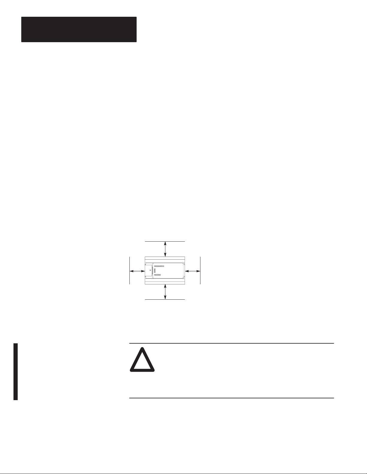
The following figure shows the recommended minimum spacing for the
controller. (Refer to appendix A for controller dimensions.)
Mounting the Controller
Top
A
Bottom
B
A. Greater than or equal to 50.8 mm (2 in.).
SideSide
A
B
B. Greater than or equal to 50.8 mm (2 in.).
20142
This equipment is suitable for Class I, Division 2, Groups A, B, C, D or
non-hazardous locations only, when product or packaging is marked.
A
TTENTION
!
•Substitution of components may impair suitability for Class I,
Division 2.
– Explosion Hazard:
•This product must be installed in an enclosure. All cables
connected to the product must remain in the enclosure or be
protected by conduit or other means.
The controller should be mounted horizontally within an enclosure, using a
DIN rail or mounting screws. Copy the template from page A–8 to help you
space and mount the controller properly.
1–12
Page 29
Chapter 1
ass I Di isi 2 a ar s
Installing Y
our Controller
ATTENTION: Be careful of metal chips when drilling
mounting holes for your controller. Drilled fragments that fall
!
into the controller could cause damage. Do not drill holes above
a mounted controller if the protective wrap is removed.
Use only the following communication cables in Class I, Division 2
Hazardous Locations.
Environment Classification Communication Cable
Class I, Division 2 Hazardous
Environment
1761-CBL-PM02 Series C
1761-CBL-HM02 Series C
1761-CBL-AM00 Series C
1761-CBL-AP00 Series C
2707-NC8 Series B
2707-NC9 Series B
2707-NC10 Series B
2707-NC11 Series B
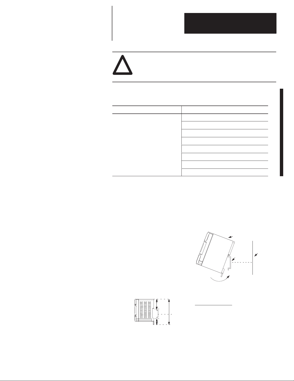
Using
a DIN Rail
Use 35 mm (1.38 in.) DIN rails, such as item number 199-DR1 or 1492-DR5
from Bulletin 1492.
To install your controller on the DIN rail:
1.Mount your DIN rail. (Make sure that the
placement of the controller on the DIN rail
meets the recommended spacing
requirements. Refer to controller
dimensions in appendix A.)
2.Hook the top slot over the DIN rail.
3.While pressing the controller against the
rail, snap the controller into position.
4.Leave the protective wrap attached until you
are finished wiring the controller.
B
A
DIN
Rail
C
Call-out Dimension
A 84 mm (3.3 in.)
B 33 mm (1.3 in.)
C 16 mm (.63 in.)
Side View
Protective Wrap
Mounting
DIN
Rail
Template
20146
1–13
Page 30

Chapter 1
Installing Y
our Controller
To remove your controller from the DIN rail:
1.Place a screwdriver in the DIN rail latch at
the bottom of the controller.
2.Holding the controller, pry downward on
the latch until the controller is released
from the DIN rail.
Side View
Using Mounting Screws
To install your controller using mounting screws:
Important: Leave the protective wrap
attached until you are
finished wiring the controller.
1.Use the mounting template from
page A–8.
2.Secure the template to the mounting
surface. (Make sure your controller
is spaced properly
3.Drill holes through the template.
4.Remove the mounting template.
5.Mount the controller.
.)
DIN
Rail
20147
Mounting
Template
Protective Wrap
(remove
after wiring)
Mounting Your Controller V
ertically
Your controller can also be mounted vertically within an enclosure using
mounting screws or a DIN rail. To insure the stability of your controller, we
recommend using mounting screws.
To insure the controller’s reliability, the following environmental
specifications must not be exceeded.
A
Top
SideSide
A
Bottom
A. Greater than or equal
to 50.8 mm (2 in.).
A
Description: Specification:
Operating
Temperature
Operating Shock
(Panel mounted)
A
Operating Shock
(DIN rail mounted)
➀
DC input voltage derated linearly from +30°C (30V to 26.4V).
0°C to +40°C (+32°F to +113°F)
9.0g peak acceleration (11±1 ms duration)
3 times each direction, each axis
7.0g peak acceleration (11±1 ms duration)
3 times each direction, each axis
➀
1–14
Note: When mounting your controller vertically, the nameplate should be
facing downward.
Page 31

Chapter
2
Wiring Your Controller
This chapter explains how to wire your MicroLogix 1000 Programmable
Controller. Topics include:
• grounding guidelines
• sinking and sourcing circuits
• wiring recommendations
• wiring diagrams, input voltage ranges, and output voltage ranges
Grounding
Guidelines
In solid-state control systems, grounding helps limit the effects of noise due
to electromagnetic interference (EMI). Use the heaviest wire gauge listed for
wiring your controller with a maximum length of 152.4 mm (6 in.). Run the
ground connection from the ground screw of the controller (third screw from
left on output terminal rung) to the ground bus.
Important:
!
This symbol denotes a functional earth ground terminal
which provides a low impedance path between electrical circuits
and earth for non-safety purposes, such as noise immunity
improvement.
Protective
Wrap (remove after wiring)
ATTENTION: All devices that connect to the user 24V power
supply or to the RS-232 channel must be referenced to chassis
ground or floating. Failure to follow this procedure may result in
property damage or personal injury.
ATTENTION: Chassis ground, user 24V ground, and RS-232
ground are internally connected. You must connect the chassis
!
ground terminal screw to chassis ground prior to connecting any
devices.
ATTENTION: On the 1761-L10BWB, 1761-L16BWB,
1761-L16BBB, 1761-L20BWB-5A, 1761-L32BBB, and 1761-L32BWB
!
controllers, the user supply 24V dc IN and chassis ground are
internally connected.
2–1
Page 32

Chapter 2
Wiring Your Controller
You must also provide an acceptable grounding path for each device in your
application. For more information on proper grounding guidelines, see the
Industrial Automation Wiring and Grounding Guidelines, publication 1770-4.1.
ATTENTION: Remove the protective wrap before applying
power to the controller. Failure to remove the wrap may cause
!
the controller to overheat.
Sinking
and Sourcing Circuits
Any MicroLogix 1000 DC inputs can be configured as sinking or sourcing
depending on how the DC COM terminal is wired.
Mode: Definition:
The input energizes when high-level voltage is applied to the input terminal
Sinking
Sourcing
Sinking
and Sourcing W
1761-L32BWA (Wiring diagrams also apply to 1761-L20BWA-5A,
-L16BWA, -L10BWA.)
Sinking Inputs
VDC (–)
for Sinking
VDC (+) for Sinking
(active high). Connect the power supply VDC (–) to the MicroLogix DC COM
terminal.
The input energizes when low-level voltage is applied to the input terminal
(active low). Connect the power supply VDC (+) to the MicroLogix DC COM
terminal.
iring Examples
Sourcing Inputs
14–30
VDC (+) for Sourcing
VDC
VDC (–) for Sourcing
2–2
DC
+
24V –
COM
DC OUT
Sourcing Inputs
VDC (+)
for Sourcing
DC
+
24V –
COM
DC OUT
I/0 I/1 I/2 I/3 I/4 I/5 I/6 I/7 I/8 I/11 I/12 I/13 I/14 I/15 I/16 I/17 I/18 I/19
VDC (–) for Sourcing
I/0 I/1 I/2 I/3 I/4 I/5 I/6 I/7 I/8 I/11 I/12 I/13 I/14 I/15 I/16 I/17 I/18 I/19
DC
COM
VDC (–) for Sinking
DC
COM
I/9 I/10
Sinking
I/9 I/10
Inputs
14–30 VDC
VDC (+)
for Sinking
Page 33

Chapter 2
A
Wiring Your Controller
1761-L32BWB, -L32BBB (Wiring Diagrams also apply to 1761-L20BWB-5
-L16BWB, -L10BWB, -L16BBB.)
Sinking
Inputs
Sourcing Inputs
Wiring Recommendations
NOT
USED
NOT
USED
VDC (–) for Sinking
NOT
DC
USED
COM
Sourcing Inputs
VDC (+) for Sourcing
NOT
DC
USED
I/0 I/1 I/2 I/3 I/4 I/5 I/6 I/7 I/8 I/11 I/12 I/13 I/14 I/15 I/16 I/17 I/18
COM
!
14–30 VDC
VDC (+) for Sinking
I/0 I/1 I/2 I/3 I/4 I/5 I/6 I/7 I/8 I/11 I/12 I/13 I/14 I/15 I/16 I/17 I/18
VDC (+) for Sourcing
DC
COM
I/9 I/10
14–30 VDC
VDC (–) for Sourcing
Sinking Inputs
14–30 VDC
VDC (–) for Sourcing
VDC (–) for Sinking
DC
COM
14–30 VDC
VDC (+) for Sinking
I/9 I/10
ATTENTION: Before you install and wire any device,
disconnect power to the controller system.
I/19
I/19
The following are general recommendations for wiring your controller
system.
• Each wire terminal accepts 2 wires of the size listed below:
Wire Type Wire Size (2 wire maximum per terminal screw)
Solid #14 to #22 AWG
Stranded #16 to #22 AWG
Refer to page 2–23 for wiring your high-speed counter.
Important: The diameter of the terminal screw heads is 5.5 mm
(0.220 in.). The input and output terminals of the micro
controller are designed for the following spade lugs:
2–3
Page 34

Chapter 2
Wiring Your Controller
Call-out Dimension
C
E
L
W
X
C+X
We recommend using either of the following AMP spade
lugs: part number 53120-1, if using 22–16 AWG, or part
number 53123-1, if using 16–14 AWG.
Important: If you use wires without lugs, make sure the wires are
securely captured by the pressure plate. This is
particularly important at the four end terminal positions
where the pressure plate does not touch the outside wall.
6.35 mm (0.250 in.)
10.95 mm (0.431 in.) maximum
14.63 mm (0.576 in.) maximum
6.35 mm (0.250 in.)
3.56 mm (0.140 in.)
9.91 mm (0.390 in.) maximum
ATTENTION: Be careful when stripping wires. Wire
fragments that fall into the controller could cause damage. Do
!
!
not strip wires above a mounted controller if the protective wrap
is removed.
Protective
Wrap (remove after wiring)
ATTENTION: Remove the protective wrap before applying
power to the controller. Failure to remove the wrap may cause
the controller to overheat.
20148i
2–4
Page 35

Chapter 2
Wiring Your Controller
ATTENTION: Calculate the maximum possible current in each
power and common wire. Observe all electrical codes dictating
!
the maximum current allowable for each wire size. Current
above the maximum ratings may cause wiring to overheat, which
can cause damage.
ATTENTION: United States Only: If the controller is installed
within a potentially hazardous environment, all wiring must
!
comply with the requirements stated in the National Electrical
Code 501-4 (b).
• Allow for at least 50 mm (2 in.) between I/O wiring ducts or terminal
strips and the controller.
• Route incoming power to the controller by a path separate from the
device wiring. Where paths must cross, their intersection should be
perpendicular.
Important: Do not run signal or communications wiring and power
wiring in the same conduit. Wires with different signal
characteristics should be routed by separate paths.
• Separate wiring by signal type. Bundle wiring with similar electrical
characteristics together.
• Separate input wiring from output wiring.
• Label wiring to all devices in the system. Use tape, shrink-tubing, or
other dependable means for labeling purposes. In addition to labeling,
use colored insulation to identify wiring based on signal characteristics.
For example, you may use blue for dc wiring and red for ac wiring.
2–5
Page 36

Chapter 2
Wiring Your Controller
Wiring Diagrams, Discrete
Input and Output V
oltage
Ranges
The following pages show the wiring diagrams, discrete input voltage ranges
and discrete output voltage ranges. Controllers with dc inputs can be wired
as either sinking or sourcing configurations. (Sinking and sourcing does not
apply to ac inputs.)
Important:
This symbol denotes a functional earth ground terminal
which provides a low impedance path between electrical circuits
and earth for non-safety purposes, such as noise immunity
improvement.
ATTENTION: The 24V dc sensor power source should not be
used to power output circuits. It should only be used to power
!
input devices (e.g. sensors, switches). Refer to page 1–3 for
information on MCR wiring in output circuits.
1761-L16AWA Wiring Diagram
L2/N
79–132V ac
L1
L2/N L1
79–132V ac
NOT
NOT
USED
USED
85–264 VAC
L1
L2/N
VAC
1
V
AC 1
COM
1761-L16AWA
0V ac 20V ac
Off
1761-L16AWA
0V ac 264V ac5V ac
0V dc 125V dc5V dc
?
AC
COM
AC
COM
VAC
VAC
VDC O/0
CR CR
V
Input V
VAC
VDC O/1
VDC O/2 O/3
AC 2
V
AC 2
COM
oltage Range
VDC 1
VDC 1
COM
VAC
VDC O/4
VDC 2
?
Output V
oltage Range
Operating Range
CR
VDC 2
COM
VAC
VDC
VDC 3
79V ac
O/5
CR
VDC 3
COM
I/9I/0 I/1 I/2 I/3 I/4 I/5 I/6 I/7 I/8
132V ac
On
2–6
Page 37

1761-L32AWA Wiring Diagram
Chapter 2
Wiring Your Controller
79–132V ac
L2/N
NOT
NOT
AC
USED
85–264 VAC
L1 L2/N
VAC
USED
1
I/0 I/1 I/2 I/3 I/4 I/5 I/6 I/7 I/8 I/11 I/12 I/13 I/14 I/15 I/16 I/17 I/18
COM
VAC
VDC
V
AC 1
COM
1761-L32AWA
0V ac 20V ac
Off
L1 L2/N L1
AC
COM
VAC
O/0
VDC
CR CR CRCR CR
V
AC 2
VAC
O/1
VDC
VDC 1
V
AC 2
COM
Input V
VAC
O/2 O/3
VDC
VDC 2
VDC 1
COM
oltage Range
O/4 O/5 O/6
79–132V ac
I/9 I/10
VAC
VDC
CR CRCR CR
VDC 3
VDC 2
COM
O/8O/7 O/9 O/10 O/11
VDC 3
COM
?
I/19
CR
132V ac79V ac
On
1761-L32AWA
0V ac 264V ac5V ac
0V dc 125V dc5V dc
?
Output V
oltage Range
Operating Range
2–7
Page 38

Chapter 2
ÉÉÉ
Wiring Your Controller
1761-L10BWA Wiring Diagram (Sinking Input Configuration)
Note: Refer to page 2–2 for additional input configuration options.
14–30V dc
+
DC OUT
24V –
VDC +
VDC
Com
DC
I/0 I/1 I/2 I/3 I/4 I/5
COM
DC
COM
VDC
Com
VDC +
NOT
USED
NOT
USED
NOT
USED
NOT
USED
Hardware
V
AC 1
V
AC 1
COM
1761-L10BWA
0V dc 5V dc
85–264 VAC
L1
L2/N
VAC
VDC O/0
Input V
VAC
VDC O/1
CR CR CR
VAC
VAC
VDC O/2 O/3
2
V
AC 2
COM
VDC 1
VDC 1
COM
oltage Range
14V dc
0V dc 5V dc 14V dc
Off
1761-L10BWA
?
Output V
oltage Range
0V ac 264V ac5V ac
0V dc 125V dc5V dc
?
Operating Range
VAC
VDC
VDC 2
CR
VDC 2
COM
NOT
USED
VDC 3
NOT
NOT
USED
USED
VDC 3
COM
26.4V dc @ 55°C (131
30V dc @ 30
On
°
C (86° F)
° F)
2–8
Page 39

Chapter 2
Wiring Your Controller
1761-L16BWA W
iring Diagram (Sinking Input Configuration)
Note: Refer to page 2–2 for additional input configuration options.
14–30V dc
VAC
VDC O/4
VDC 2
VDC 1
COM
VDC 2
COM
VDC +
I/9
VAC
VDC
CR
VDC 3
O/5
VDC 3
COM
VDC
Com
+
24V –
DC
COM
DC OUT
85–264 VAC
L1
L2/N
V
AC 1
V
AC 1
COM
1761-L16BWA
VDC +
I/0 I/1 I/2 I/3 I/4 I/5 I/6 I/7 I/8
VAC
VDC O/0
VAC
VDC O/1
CR CR CR
VAC
Input V
VDC
Com
DC
COM
VAC
VDC O/2 O/3
2
VDC 1
V
AC 2
COM
oltage Range
Hardware
0V dc 5V dc
0V dc 5V dc
Off
1761-L16BWA
0V ac 264V ac5V ac
0V dc 125V dc5V dc
?
?
Output V
14V dc
14V dc
oltage Range
Operating Range
26.4V dc @ 55°C (131
30V dc @ 30°C (86° F)
On
° F)
2–9
Page 40

Chapter 2
Wiring Your Controller
1761-L32BWA Wiring Diagram (Sinking Input Configuration)
Note: Refer to page 2–2 for additional input configuration options.
VDC
Com
DC
+
24V –
COM
DC OUT
85–264 VAC
L1 L2/N
VAC
1
V
AC 1
COM
1761-L32BWA
0V dc 5V dc
VDC +
I/0 I/1 I/2 I/3 I/4 I/5 I/6 I/7 I/8 I/11 I/12 I/13 I/14 I/15 I/16 I/17 I/18 I/19
VAC
VAC
VDC O/0
VDC O/1
CR CR CRCR CR
V
AC 2
VDC
Com
DC
COM
VAC
VDC O/2 O/3
VDC 1
V
AC 2
COM
Input V
VAC
VDC O/4 O/5 O/6
VDC 2
VDC 1
COM
oltage Range
14V dc
0V dc 5V dc 14V dc
Off
?
14-30 V dc
I/9 I/10
VAC
VDC O/8O/7 O/9 O/10 O/11
CR CRCR CR
VDC 3
VDC 2
COM
CR
VDC 3
COM
26.4V dc @ 55°C (131
30V dc @ 30
On
°
C (86° F)
VDC +
° F)
2–10
1761-L32BWA
0V ac 264V ac5V ac
0V dc 125V dc5V dc
?
Output V
oltage Range
Operating Range
Page 41

Chapter 2
ЙЙЙЙЙЙЙЙЙ
Wiring Your Controller
1761-L10BWB Wiring Diagram (Sinking Input Configuration)
Note: Refer to page 2–2 for additional input configuration options.
14–30 VDC
VDC
Com
NOT
USED
DC IN
+
24V –
Input V
DC
I/0 I/1 I/2 I/3 I/4 I/5
COM
VAC
VAC
VDC O/0
VDC O/1
CR
V
oltage Range
NOT
USED
VDC 1
VDC 1
COM
1761-L10BWB
0V dc 5V dc 14V dc
Off
?
VDC +
AC 1
V
COM
AC 1
14–30 VDC
VDC
VDC +
Com
DC
COM
VAC
VDC O/2 O/3
VDC 2
VDC 2
COM
VAC
VDC
VDC 3
NOT
USED
CR
VDC 3
COM
NOT
NOT
NOT
USED
USED
USED
NOT
NOT
NOT
USED
USED
USED
26.4V dc @ 55°C (131
On
Hardware
° F)
0V ac 264V ac5V ac
0V dc 125V dc5V dc
?
1761-L10BWB
Output V
oltage Range
Operating Range
2–11
Page 42

Chapter 2
Wiring Your Controller
1761-L16BWB Wiring Diagram (Sinking Input Configuration)
Note: Refer to page 2–2 for additional input configuration options.
NOT
USED
VDC 1
VDC 1
COM
1761-L16BWB
0V dc 5V dc
Off
+
DC IN
NOT
USED
24V –
DC
COM
VDC
Com
14–30V dc
VDC +
VAC
VAC
VDC O/0
VDC O/1
CR CR CR
V
AC 1
Input V
VDC
Com
DC
COM
VAC
VDC O/2 O/3
VDC 2
V
AC 1
COM
oltage Range
14–30V dc
VAC
VDC O/4 O/5
CR
VDC 3
VDC 2
VDC 3
COM
COM
14V dc
?
VAC
VDC
VDC 4
VDC +
VDC 4
COM
I/9I/0 I/1 I/2 I/3 I/4 I/5 I/6 I/7 I/8
26.4V dc @ 55°C (131
On
° F)
2–12
1761-L16BWB
0V ac 264V ac5V ac
0V dc 125V dc5V dc
?
Output V
oltage Range
Operating Range
Page 43

Chapter 2
Wiring Your Controller
1761-L32BWB Wiring Diagram (Sinking Input Configuration)
Note: Refer to page 2–2 for additional input configuration options.
Sinking Configuration
VDC
Com
NOT
NOT
DC
USED
DC IN
+
24V –
USED
VDC 1
I/0 I/1 I/2 I/3 I/4 I/5 I/6 I/7 I/8 I/11 I/12 I/13 I/14 I/15 I/16 I/17 I/18
COM
VAC
VDC
VDC 1
COM
1761-L32BWB
0V dc 5V dc
14–30V dc
VDC +
VAC
O/0
VDC
CR CR CRCR CR
V
AC 1
VDC +
DC
COM
VAC
O/1
VDC
VDC 2
V
AC 1
COM
Input V
VDC 2
COM
VAC
VDC
VDC 3
O/4 O/5 O/6
O/2 O/3
oltage Range
14V dc
Sourcing Configuration
14–30V dc
I/9 I/10
VAC
VDC
CR CRCR CR
VDC 4
VDC 3
COM
O/8O/7 O/9 O/10 O/11
CR
VDC 4
COM
26.4V dc @ 55°C (131
VDC
Com
I/19
° F)
Off
1761-L32BWB
0V ac 264V ac5V ac
0V dc 125V dc5V dc
?
?
Output V
On
oltage Range
Operating Range
2–13
Page 44

Chapter 2
Wiring Your Controller
1761-L32AAA Wiring Diagram
79–132V ac
L2/N
NOT
NOT
AC
USED
85–264 VAC
L1 L2/N
VAC
USED
0
I/0 I/1 I/2 I/3 I/4 I/5 I/6 I/7 I/8 I/11 I/12 I/13 I/14 I/15 I/16 I/17 I/18
COM
VAC
VDC
V
AC 0
COM
1761-L32AAA
0V ac 20V ac
Off
L1 L2/N L1
AC
COM
VAC
VDC
V
AC 1
O/1
V
COM
AC 1
VAC
V
AC 2
O/0
CR CR CRCR CR
Input V
VAC
O/2 O/3
V
AC 2
COM
V
AC 3
O/4 O/5 O/6
oltage Range
79–132V ac
I/9 I/10
VAC
CR CRCR CR
V
AC 4
V
AC 3
COM
O/8O/7 O/9 O/10 O/11
CR
V
AC 4
COM
79V ac
?
On
I/19
132V ac
1761-L32AAA
Output V
0V ac 264V ac85V ac
?
oltage Range
Operating Range
2–14
Page 45

Chapter 2
Wiring Your Controller
1761-L16BBB Wiring Diagram (Sinking Input Configuration)
Note: Refer to page 2–2 for additional input configuration options.
VDC
Com
NOT
NOT
DC IN
+
24V –
VDC 1
COM
USED
DC
COM
USED
VDC 1
1761-L16BBB
14–30V dc
VDC +
I/0 I/1 I/2 I/3 I/4 I/5 I/6 I/7 I/8
VAC
VAC
VDC O/0
VDC O/1DC24V+ O/2 O/3 O/4 O/5
CR
V
AC 1
V
COM
AC 1
V
AC 2
Input V
VDC
Com
DC
COM
Sourcing Outputs
VDC 2
V
COM
AC 2
VDC 2
COM
oltage Range
0V dc 5V dc 14V dc
Off
?
14–30V dc
DC
24V–
VDC +
NOT
USED
I/9
26.4V dc @ 55°C (131
On
Hardware
° F)
1761-L16BBB
Output V
oltage Range
0V dc 26.4V dc20.4V dc
?
Operating Range
2–15
Page 46

Chapter 2
Wiring Your Controller
1761-L32BBB Wiring Diagram (Sinking Input Configuration)
Note: Refer to page 2–2 for additional input configuration options.
Sinking Configuration
NOT
NOT
USED
USED
DC IN
+
24V –
VDC 1
VDC 1
COM
1761-L32BBB
14–30V dc
VDC
Com
DC
I/0 I/1 I/2 I/3 I/4 I/5 I/6 I/7 I/8 I/11 I/12 I/13 I/14 I/15 I/16 I/17 I/18
COM
VAC
VDC
V
AC 1
V
COM
O/0
CR
AC 1
VAC
VDC
V
VDC +
AC 2
VDC +
DC
COM
DC
O/1
24V+
VDC 2
V
AC 2
COM
Input V
O/2 O/3 O/4 O/5 O/6
VDC 2
COM
oltage Range
0V dc 5V dc 14V dc
I/9 I/10
Sourcing Outputs
Sourcing Configuration
14–30V dc
O/8O/7 O/9 O/10 O/11
DC
NOT
24V–
USED
26.4V dc @ 55°C (131
VDC
Com
I/19
° F)
Off
1761-L32BBB
?
Output V
On
oltage Range
0V dc 26.4V dc20.4V dc
?
Operating Range
2–16
Page 47

Chapter 2
Wiring Your Controller
1761-L20AWA-5A Wiring Diagram
Note: Refer to pages 2–20 through 2–22 for additional information on
analog wiring.
NOT
USED
85–264 VAC
L1 L2/N
79–132V ac
L2/N
NOT
AC
USED
VAC
I/0 I/1 I/2 I/3 I/4 I/5 I/6 I/7 I/8 I/11
COM
VAC
VDC O/0
1
V
AC 1
COM
L1 L2/N L1
AC
COM
VAC
VDC O/1
CR CR CRCR CR
V
AC 2
VAC
VDC O/2 O/3
VDC 1
V
AC 2
COM
79–132V ac
VAC
VDC O/4 O/5 O/6
VDC 2
VDC 1
COM
1761-L20AWA-5A Discrete Input Voltage Range
0V ac 20V ac
Off
?
I/9 I/10
CR
VDC 2
COM
NOT
USEDO/7
IA
SHD
OA
SHD
IA/0
V (+)
OA/0
V (+)
Analog
Channel
Analog
Channels
IA/1
V (+)
OA/0
I (+)
IA
I (+)
SHD
(–)
OA
(–)
(–)
I (+)
IA
IA/3
IA/2
IA
132V ac79V ac
On
1761-L20AWA-5A Relay Output Voltage Range
0V ac 264V ac5V ac
0V dc 125V dc5V dc
?
Operating Range
2–17
Page 48

Chapter 2
Wiring Your Controller
1761-L20BWA-5A Wiring Diagram (Sinking Input Configuration)
Note: Refer to page 2–2 for additional discrete configuration options.
Refer to pages 2–20 through 2–22 for additional information on
analog wiring.
14–30V dc
VAC
VDC O/4 O/5 O/6
VDC 2
VDC 1
COM
I/9 I/10
+
24V –
DC OUT
85–264 VAC
L1 L2/N
VAC
1
VDC (–)
VDC (+)
VDC (–)
DC
I/0 I/1 I/2 I/3 I/4 I/5 I/6 I/7 I/8 I/11
COM
VAC
VDC O/0
CR CR CRCR CR
V
AC 1
COM
VAC
VDC O/1
V
AC 2
V
COM
DC
COM
VAC
VDC O/2 O/3
VDC 1
AC 2
1761-L20BWA-5A Discrete Input Voltage Range
0V dc 5V dc
0V dc 5V dc 14V dc
14V dc
VDC (+)
CR
VDC 2
COM
NOT
USEDO/7
IA
SHD
Analog
Channels
IA/1
IA/0
V (+)
V (+)
OA/0
OA/0
OA
SHD
V (+)
I (+)
Analog
Channel
26.4V dc @ 55°C (131
30V dc @ 30
IA
I (+)
(–)
SHD
OA
(–)
(–)
I (+)
IA
IA/3
IA/2
IA
° F)
°
C (86° F)
2–18
Off
?
1761-L20BWA-5A Relay Output Voltage Range
0V ac 264V ac5V ac
0V dc 125V dc5V dc
?
Operating Range
On
Page 49

Chapter 2
Wiring Your Controller
1761-L20BWB-5A Wiring Diagram (Sinking Input Configuration)
Note: Refer to page 2–2 for additional discrete configuration options.
Refer to pages 2–20 through 2–22 for additional information on
analog wiring.
NOT
USED
DC IN
+
24V –
NOT
USED
VDC 1
14–30V dc
I/0 I/1 I/2 I/3 I/4 I/5 I/6 I/7 I/8 I/11
VAC
VDC O/0
CR CR CRCR CR
DC
COM
VDC 1
COM
VDC (–)
VDC +
VAC
VDC O/1
V
AC 1
VDC (–)
DC
COM
VAC
VDC O/2 O/3
VDC 2
V
AC 1
COM
14–30V dc
VAC
VDC O/4 O/5 O/6
VDC 3
VDC 2
COM
1761-L20BWB-5A Discrete Input Voltage Range
0V dc 5V dc 14V dc
I/9 I/10
VDC (+)
CR
VDC 3
COM
NOT
USEDO/7
IA
SHD
OA
SHD
Analog
Channels
IA/1
IA/0
V (+)
OA/0
V (+)
V (+)
Analog
Channel
OA/0
I (+)
IA
(–)
OA
(–)
26.4V dc @ 55°C (131
IA
SHD
IA/2
I (+)
(–)
I (+)
IA
IA/3
° F)
Off
?
1761-L20BWB-5A Relay Output Voltage Range
0V ac 264V ac5V ac
0V dc 125V dc5V dc
?
Operating Range
On
2–19
Page 50

Chapter 2
Wiring Your Controller
Minimizing Electrical Noise on Analog Controllers
Grounding Y
our Analog Cable
Inputs on analog employ digital high frequency filters that significantly
reduce the ef
the variety of applications and environments where analog controllers are
installed and operated, it is impossible to ensure that all environmental noise
will be removed by the input filters.
Several specific steps can be taken to help reduce the effects of
environmental noise on analog signals:
fects of electrical noise on input signals. However, because of
• install the MicroLogix 1000 system in a properly rated (i.e., NEMA)
enclosure. Make sure that the MicroLogix 1000 system is properly
grounded.
• use Belden cable #8761 for wiring the analog channels making sure that
the drain wire and foil shield are properly earth grounded.
• route the Belden cable separate from any other wiring. Additional noise
immunity can be obtained by routing the cables in grounded conduit.
A system may malfunction due to a change in the operating environment
after a period of time. We recommend periodically checking system
operation, particularly when new machinery or other noise sources are
installed near the MicroLogix 1000 system.
Use shielded communication cable (Belden #8761). The Belden cable has
two signal wires (black and clear), one drain wire and a foil shield. The
drain wire and foil shield must be grounded at one end of the cable. Do not
earth ground the drain wire and foil shield at both ends of the cable.
2–20
Insulation
Clear Wire
Foil Shield
Black Wire
Drain Wire
Page 51

Chapter 2
Wiring Your Controller
Wiring Your Analog Channels
Analog input circuits can monitor current and voltage signals and convert
them to serial digital data. The analog output can support either a voltage or
a current function.
IA/3
I (+)
OA/0
I (+)
Sensor 3
(I) Current
IA
(–)
OA
(–)
Sensor 4
(I) Current
meter
Sensor 1
(V) V
oltage
Jumper
unused
inputs.
Sensor 2
(V) Voltage
I/10 I/11
VAC
O/4 O/5 O/6
VDC
IA
SHD
IA/0
V (+)
IA/1
V (+)
IA
(–)
NOT
O/7
USED
You can configure either voltage
or current output operation.
IA
SHD
OA
SHD
IA/2
I (+)
OA/0
V (+)
– OR –
For increased noise immunity, connect a ground wire directly from the shield
terminals to chassis ground.
Important: The controller does not provide loop power for analog inputs.
Use a power supply that matches the transmitter specifications.
2-Wire Transmitter
Supply
3-Wire Transmitter
Supply
4-Wire Transmitter
Supply
Transmitter
+–
+Power
–
Controller
IA/0 – 3 (+)
IA (–)
Transmitter
Supply Signal
GND
+Power
–
Transmitter
Supply Signal
+Power
–
+–+
–
Controller
IA/0 – 3 (+)
IA (–)
Controller
IA/0 – 3 (+)
IA (–)
2–21
Page 52

Chapter 2
Wiring Your Controller
Analog Voltage and Current Input and Output Ranges
The following drawings show the analog voltage input range, analog current
input range, analog voltage output range and analog current output range.
Analog Voltage Input Range
–24V dc
Underrange
–10.5V dc 10.5V dc
Operating Range
Overrange
24V dc
Analog Current Input Range
–50 mA 50 mA
Underrange
Note: The analog voltage inputs are protected to withstand the application of
24V dc without damage to the controller. The analog current inputs are
protected to withstand the application of 50 mA without damage.
–21 mA 21 mA
Operating Range
Overrange
Analog Voltage Output Range
0V dc 10V dc
Operating Range
Analog Current Output Range
4 mA
Operating Range
Note: The analog outputs are protected to withstand the short circuiting of
the voltage or current outputs without damage to the controller.
For information on analog signal and data word values using the nominal
transfer function formula, see page 7–4.
20 mA
2–22
Page 53

Chapter 2
Wiring Your Controller
Wiring Your Controller for High-Speed Counter Applications
To wire the controller for high-speed counter applications, use input
terminals I/0, I/1, I/2, and I/3. Refer to chapter 14 for information on using
the high-speed counter.
Shielded cable is required for high-speed input signals 0–3 when the filter
setting is set to either 0.10 ms or 0.075 ms. We recommend Belden #9503
for lengths up to 305 m (1000 ft). Shields should be grounded only at the
signal source end of the cable. Ground the shield to the case of the signal
source, so energy coupled to the shield is not delivered to the signal source’s
electronics.
2–23
Page 54

Chapter
3
Connecting the System
This chapter describes how to wire your controller system. The method you
use and cabling required to connect your controller depends on what type of
system you are employing. Specifically, this chapter contains information
on:
• connecting the HHP
• DH-485 connections
• establishing communication
Important: In order to access the functionality of the Series C or later
discrete and all MicroLogix 1000 analog controllers, you must
configure your program to operate with these controllers. See
page 18–18 for more information.
Connecting
the HHP
Use a serial cable to connect the MicroLogix 1000 HHPs RS-232
communication channel to the MicroLogix 1000 programmable controller, as
shown below.
ATTENTION: Chassis ground, user 24V ground, and RS-232
ground are internally connected. You must connect the chassis
!
ground terminal screw to chassis ground prior to connecting any
devices. It is important that you understand your programming
device’s grounding system before connecting to the controller.
MicroLogix 1000
Programmable Controller
1761-CBL-HM02
Hand-Held Programmer
3–1
Page 55

Chapter 3
Connecting the System
The 1761-CBL-HM02 Series B or higher cable with pinouts is shown below.
Use this cable to connect the MicroLogix 1000 HHP to the MicroLogix 1000
Programmable Controller.
36
1
58
7
8–pin Locking Mini DIN
2
4
Connects to the ControllerConnects to the HHP
8–pin Mini DIN
678
3
5
4
12
20188
Programming Device
8–Pin
+24V
1
–24V
2
3
RXD
4
5
6
TXD
7
GND
8
Controller
+24V 1
–24V 2
TXD
RXD
GND
8–Pin
3
7
5
6
4
8
3–2
Page 56

Chapter 3
Connecting the System
Connecting to a DH-485 Network
Important: Only Series C or later MicroLogix 1000 discrete controllers and
all MicroLogix 1000 analog controllers support DH-485
network connections. In order to access the DH-485
functionality of the Series C or later MicroLogix 1000 discrete
and MicroLogix 1000 analog controllers, you must configure
your program to operate with these controllers. See page 18–18
for more information.
MicroLogix
discrete or MicroLogix 1000 analog)
1000 (Series C or later
PC
APS
PC to port 1
or port 2
or
1761-CBL-AC00
1747-CP3
or
1761-CBL-AM00
1761-CBL-HM02
AIC+
(1761-NET-AIC)
24V dc
(A user supply is not needed if a
MicroLogix 1000 controller is
connected to port 2.)
MicroLogix DH-485 Network
or
connection from
port 1 or port 2
to MicroLogix
1761-CBL-AP00
or
1761-CBL-PM02
AIC+
(1761-NET-AIC)
24V dc
(user supplied)
1761-CBL-AP00
1761-CBL-PM02
DB-9 RS-232 port
mini-DIN 8 RS-232 port
DH-485 port
Recommended Tools
To connect a DH-485 network, you need tools to strip the shielded cable and
to attach the cable and terminators to the AIC+ Advanced Interface
Converter. We recommend the following equipment (or equivalent):
Description Part Number Manufacturer
Shielded Twisted Pair Cable #3106A or #9842 Belden
Stripping Tool 45-164 Ideal Industries
1/8 ” Slotted Screwdriver Not Applicable Not Applicable
DH-485 Communication Cable
The suggested DH-485 communication cable is either Belden #3106A or
#9842. The cable is jacketed and shielded with one or two twisted wire pairs
and a drain wire.
One pair provides a balanced signal line, and one additional wire is used for
a common reference line between all nodes on the network. The shield
reduces the effect of electrostatic noise from the industrial environment on
network communication.
3–3
Page 57

Chapter 3
Connecting the System
The communication cable consists of a number of cable segments
daisy-chained together. The total length of the cable segments cannot exceed
1219 m (4000 ft).
When cutting cable segments, make them long enough to route them from
one AIC+ to the next with sufficient slack to prevent strain on the connector.
Allow enough extra cable to prevent chafing and kinking in the cable.
Use these instructions for wiring the Belden #3106A or #9842 cable. (If you
are using standard Allen-Bradley cables, see the Cable Selection Guide on
page 3–8.)
Connecting the Communication Cable to the DH-485 Connector
Important: A daisy-chained network is recommended. We do not
recommend the following:
Belden
#3106A or
#9842
Connector
Connector
Incorrect
Belden
#3106A or
#9842
Single Cable Connection
Orange with White Stripes
White with Orange Stripes
Shrink Tubing
Recommended
Blue (#3106A) or
Blue with White Stripes (#9842)
Multiple Cable Connection
Belden
#3106A or
#9842
Connector
6 Termination
5A
4B
3 Common
2 Shield
1 Chassis Ground
Drain Wire
to Previous Device
3–4
to Successive Device
Page 58

Chapter 3
e
e
e
Connecting the System
The table below shows connections for Belden #3106A.
For this Wire/Pair Connect this Wire To this Terminal
Shield/Drain Non-jacketed T
Blue Blue Terminal 3 – (Common)
White/Orang
White with Orange Stripe Terminal 4 – (Data B)
Orange with White Stripe Terminal 5 – (Data A)
erminal 2 – Shield
The table below shows connections for Belden #9842.
For this Wire/Pair Connect this Wire To this Terminal
Shield/Drain Non-jacketed T
Blue/Whit
White/Orang
➀
To prevent confusion when installing the communication cable, cut back the white with blue stripe wire
immediately after the the insulation jacket is removed. This wire is not used by DH-485.
White with Blue Stripe
Blue with White Stripe Terminal 3 – (Common)
White with Orange Stripe Terminal 4 – (Data B)
Orange with White Stripe Terminal 5 – (Data A)
erminal 2 – Shield
Cut back – no connection
➀
Grounding
and T
erminating the DH-485 Network
Only one connector at the end of the link must have Terminals 1 and 2
jumpered together. This provides an earth ground connection for the shield
of the communication cable.
Both ends of the network must have Terminals 5 and 6 jumpered together.
This connects the termination impedance (of 120Ω) that is built into each
AIC+ as required by the DH-485 specification.
End-of-Line Termination
Jumper
Belden
#3106A or #9842 Cable
1219 m (4000 ft) Maximum
Jumper
Jumper
3–5
Page 59

Chapter 3
Connecting the System
Connecting
the AIC+
Important: Only Series C or later MicroLogix 1000 discrete controllers and
all MicroLogix 1000 analog controllers support DH-485
network connections.
You can connect an unpowered AIC+, catalog number 1761-NET-AIC, to the
network without disrupting network activity. In addition, if a MicroLogix
1000 controller powers an AIC+ that is connected to the network, network
activity will not be disrupted should the MicroLogix 1000 controller be
removed from the AIC+.
The figure below shows the external wiring connections and specifications of
the AIC+.
AIC+ Advanced Interface Converter
(1761-NET-AIC)
3–6
Item Description
Port 1 – DB-9 RS-232, DTE
Port 2 – mini-DIN 8 RS-232
Port 3 – DH-485 Phoenix plug
DC Power Source selector switch
(cable = port 2 power source, external = external power source connected to item 5)
Terminals for external 24V dc power supply and chassis ground
For additional information on connecting to the AIC+, see the Advanced
Interface Converter (AIC+) and DeviceNet Interface (DNI) Installation
Instructions, Publication 1761-5.11.
Page 60

Chapter 3
Connecting the System
DF1 Isolated Point-to-Point Connection
AIC+
(1761-NET-AIC)
1761-CBL-AM00
1761-CBL-HM02
or
Selection Switch Up
24V dc
(Not needed in this configuration since
the MicroLogix 1000 provides power to
the AIC+ via port 2.)
DH-485 Network Connection
MicroLogix
1000 (Series C or later discrete and all analog)
connection from
port 1 or port 2
1761-CBL-AM00
AIC+
(1761-NET-AIC)
1761-CBL-
HM02
or
24V dc
(A user supply is not needed if a
MicroLogix 1000 controller is
connected to port 2.)
MicroLogix DH-485 Network
to MicroLogix
MicroLogix 1000
1761-CBL-AP00
or
1761-CBL-PM02
(1761-NET-AIC)
PC
1747-CP3 or 1761-CBL-AC00
APS
1761-CBL-AP00
1761-CBL-PM02
AIC+
24V dc
(user supplied)
PC
PC to port 1
or port 2
or
1761-CBL-AC00
1747-CP3
or
DB-9 RS-232 port
mini-DIN 8 RS-232 port
DH-485 port
DF1 Isolated Modem Connection
AIC+
(1761-NET-AIC)
1761-CBL-AM00
1761-CBL-HM02
or
Selection Switch Up
24V dc
(Not needed in this configuration
since the MicroLogix 1000 provides
power to the AIC+ via port 2.)
MicroLogix 1000
Modem
User supplied cable
3–7
Page 61

Chapter 3
17 7 P3
39f
1761
09
9
1761
09
9
1761 L M00
c177i
Connecting the System
1761-CBL-AC00
Cable
Selection Guide
1747-CP3
Cable Length Connections from to AIC+
1747-CP3
1761-CBL-AC00
Cable Length Connections from to AIC+
1761-CBL-AS03
-CBL-AS
-CBL-AS
1761-CBL-AM00
3m (9.8 ft)
45 cm (17.7 in)
1761-CBL-AS03
3m (9.8 ft)
.5m (31.17 ft)
.5m (31.17 ft)
SLC 5/03 or SLC 5/04 processor, channel 0 port 1 yes external
PC COM port port 1 yes external
PanelView 550 through NULL modem adapter port 1 yes external
Port 1 on another AIC+ port 1 yes external
1761-CBL-AS09
SLC 500 Fixed,
SLC 5/01, SLC 5/02, and SLC 5/03 processors
PanelView 550 RJ45 port port 3 yes external
1761-CBL-HM02
External
Power Supply
Required
External
Power Supply
Required
port 3 yes external
Power Selection Switch
➀
Power Selection Switch
➀
Setting
Setting
➀
➀
3–8
Cable Length Connections from to AIC+
1761-CBL-AM00 45 cm (17.7 in)
1761-CBL-HM02
➁
2m (6.5 ft)
MicroLogix 1000
to port 2 on another AIC+ port 2 yes external
➀
External power supply required unless the AIC+ is powered by the device connected to port 2, then the
selection switch should be set to cable.
➁
Series B cables or higher are required for hardware handshaking.
External
Power Supply
Required
port 2 no cable
Power Selection Switch
Setting
Page 62

Chapter 3
1761 L P00
c177i
Connecting the System
1761-CBL-AP00
Cable Length Connections from to AIC+
1761-CBL-AP00 45 cm (17.7 in)
1761-CBL-PM02
straight 9–25 pin –– modem or other communication device port 1
➁
2m (6.5 ft)
Cable Length Connections from to AIC+
SLC 5/03 or SLC 5/04 processors, channel 0 port 2 yes external
MicroLogix 1000
PanelView 550 through NULL modem adapter port 2 yes external
PC COM port port 2 yes external
user
supplied cable
➀
External power supply required unless the AIC+ is powered by the device connected to port 2, then the
selection switch should be set to cable.
➁
Series B cables or higher are required for hardware handshaking.
1761-CBL-PM02
port 1
External
Power Supply
Required
➀
yes
External
Power Supply
Required
➀
yes
Power Selection Switch
Setting
➀
external
Power Selection Switch
Setting
➀
external
3–9
Page 63

Chapter 3
Connecting the System
Recommended User-Supplied Components
These components can be purchased from your local electronics supplier.
Component Recommended Model
external power supply and chassis
ground
NULL modem adapter standard AT
straight 9–25 pin RS-232 cable see table below for port information if making own cables
DB-9 RS-232 Port 1
power supply rated for 20.4–28.8V dc
1761-CBL-AP00 or 1761-CBL-PM02
cable straight D connector
8-pin mini DIN
➀
DH-485 connector Port 3
➀
Port 1
Item
received line signal detector (DCD) same state as port 1’s DCD signal chassis ground
received data (RxD) received data (RxD) cable shield
transmitted data (TxD) transmitted data (TxD)
DTE ready (DTR) DTE ready (DTR) DH-485 data B
signal common (GRD) signal common (GRD) DH-485 data A
DCE ready (DSR) DCE ready (DSR) termination
request to send (RTS) request to send (RTS)
clear to send (CTS) clear to send (CTS)
not applicable not applicable not applicable
➀
An 8-pin mini DIN connector is used for making connections to port 2. This connector is not commercially
available. If you are making a cable to connect to port 2, you must configure your cable to connect to the
Allen-Bradley cable shown above.
➁
On port 1, pin 4 is electronically jumpered to pin 6. Whenever the AIC+ is powered on, pin 4 will match the
state of pin 6.
➂
In the 1761-CBL-PM02 cable, pins 4 and 6 are jumpered together within the DB-9 connector.
DB-9 RS-232
Port 2
(1761-CBL-PM02 cable)
DH-485 Connector
signal ground
not applicable
not applicable
Port 3
3–10
Page 64

Chapter 3
Connecting the System
Powering the AIC+
ATTENTION: If you use an external power supply, it must be
24V dc. Permanent damage will result if miswired with the
!
wrong power source.
Set the DC Power Source selector switch to EXTERNAL before connecting
the power supply to the AIC+.
Bottom View
ATTENTION: Always connect the CHS GND (chassis ground)
terminal to the nearest earth ground. This connection must be
!
made whether or not an external 24V dc supply is used.
In normal operation with the MicroLogix 1000 programmable controller
connected to port 2 of the AIC+, the controller powers the AIC+. Any AIC+
not connected to a controller requires a 24V dc power supply. The AIC+
requires 85 mA at 24V dc.
If both the controller and external power are connected to the AIC+, the
power selection switch determines what device powers the AIC+.
24VDC
DC
NEUT
CHS
GND
Power Options
Below are two options for powering the AIC+:
• Use the 24V dc user power supply (200 mA maximum) built into the
MicroLogix controller. The AIC+ is powered through a hard-wired
connection using a communication cable (1761-CBL-HM02, or
equivalent) connected to port 2.
• Use an external DC power supply with the following specifications:
– operating voltage: 24V dc +20% / –15%
– output current: 120 mA minimum
–
rated NEC
Make a hard-wired connection from the external supply to the screw
terminals on the bottom of the AIC+.
3–11
Page 65

Chapter 3
Connecting the System
ATTENTION: If you use an external power supply, it must be
24V dc. Permanent damage will result if miswired with the
!
wrong power source.
Installing and Attaching the AIC+
1. Take care when installing the AIC+ in an enclosure so that the cable
connecting the MicroLogix 1000 controller to the AIC+ does not interfere
with the enclosure door.
2. Carefully plug the terminal block into the DH-485 port on the AIC+ you
are putting on the network. Allow enough cable slack to prevent stress on
the plug.
3. Provide strain relief for the Belden cable after it is wired to the terminal
block. This guards against breakage of the Belden cable wires.
Establishing Communication
When you connect a MicroLogix 1000 controller, it automatically determines
which protocol is active (DF1 or DH-485), and establishes communication
accordingly. Therefore, no special configuration is required to connect to
either network.
However, to shorten the connection time, you can specify which protocol the
controller should attempt to establish communication with first. This is done
using the Primary Protocol bit, S:0/10. The default setting for this bit is DF1
(0). If the primary protocol bit is set to DF1, the MicroLogix 1000 controller
will attempt to connect using the configured DF1 protocol: either full-duplex
or half-duplex slave. To have the controller first attempt DH-485
communication, set this bit to 1.
For DH-485 networks that will only contain MicroLogix controllers, at least
one controller must have its primary protocol bit set to 1 so that the network
can be initialized.
3–12
Page 66

Interfac
Chapter 3
Connecting the System
Automatic
Protocol Switching
The MicroLogix 1000 Series D or later discrete and all MicroLogix 1000
analog controllers perform automatic protocol switching between DH-485
and the configured DF1 protocol. (The controller cannot automatically
switch between DF1 full-duplex and DF1 half-duplex slave.) This feature
allows you to switch from active communication on a DF1 half-duplex
network to the DH-485 protocol to make program changes.
Simply disconnect the MicroLogix controller from the DF1 half-duplex
network and connect it to your personal computer. The controller recognizes
the computer is attempting to communicate using the DH-485 protocol and
automatically switches to it. When your program changes are complete, you
can disconnect your computer, reconnect the modem, and the controller
automatically switches back to the configured DF1 protocol. For example, if
you are using the DH-485 protocol to make program changes and you
connect an HHP, you can switch to active communication on a DF1
full-duplex network.
The following baud rate limitations affect autoswitching:
• If the configured DH-485 baud rate is 19200, the configured DF1 baud
rate must be 4800 or greater.
• If the configured DH-485 baud rate is 9600, the configured DF1 baud rate
must be 2400 or greater.
DeviceNet Communications
You can also connect a MicroLogix to a DeviceNet network using the
DeviceNet Interface (DNI), catalog number 1761-NET-DNI. For additional
information on connecting the DNI, see the Advanced Interface Converter
(AIC+) and DeviceNet Interface (DNI) Installation Instructions, Publication
1761-5.11. For information on how to configure and commission a DNI, see
the DeviceNet Interface User Manual, Publication 1761-6.5.
The figure that follows identifies the ports of the DNI.
Use
this write–on
area to mark the
DeviceNet node
Address.
DNI DeviceNet
(1761-NET-DNI)
SHIEL
D CAN_H
NODE
DANGER
GND
V–
CAN_L
V+
TX/RX
NET
MOD
e
DeviceNet
(Port 1)
(Replacement
connector part no.
1761–RPL–
–
RS–232
Port 2)
(
0000)
3–13
Page 67

Chapter 3
1761 L M00
c177i
1761 L PM00
c177i
Connecting the System
Cable
Selection Guide
1761-CBL-AM00
Cable Length Connections from to DNI
1761-CBL-AM00 45 cm (17.7 in)
1761-CBL-HM02
1761-CBL-APM00 45 cm (17.7 in)
1761-CBL-PM02
➀
2m (6.5 ft)
1761-CBL-AP00
Cable Length Connections from to DNI
➀
2m (6.5 ft)
➀
Series B cables or higher are required for hardware handshaking.
MicroLogix 1000 (all series) port 2
MicroLogix 1000 (all series) port 2
SLC 5/03 or SLC 5/04 processors, channel 0 port 2
PC COM port port 2
1761-CBL-HM02
1761-CBL-PM02
3–14
Page 68

Chapter
RSLogix 500
RSLogix 500
9323-RL0100END
eries
I00
Micr
eries
4
Using Your Hand-Held Programmer
This chapter describes your MicroLogix 1000 Hand-Held Programmer
(HHP), its memory module, and its power-up procedure. It also walks you
through the start-up displays and helps you understand some of the
functionality options available to you.
Read this chapter for information about:
• your HHP
• installing memory modules
• the keys you use
• the power-up sequence
• the HHPs functional areas
• the HHPs defaults
About Your HHP
Important: The table below provides software compatibility information
necessary for full functionality of your MicroLogix 1000
controller.
Software Package Version x.x Functionality Level
Full functionality for MicroLogix 1000 Series D and
Full functionality for MicroLogix 1000 Series D and
Series C functionality only; Cannot download to
analog controllers
S
C functionality only
analog controllers
Series D or analog controllers
S
A/B functionality only
9324-RL03000END
RSLogix 500 Starter
9323-RL0100END
A.I. 500
9323-S5300D
A.I.
9323-MX300EN
o
APS
9323-PA2E
MPS
9323-PA1E
v2.10.11 or later
v2.0.57 Full functionality for Series D controllers only
v1.24
v1.05
v8.16 or later
v8.15 Series C functionality only
v8.14 or earlier
v6.04 or earlier
v1.0
The MicroLogix 1000 Hand-Held Programmer (HHP) allows you to create,
edit, monitor, and troubleshoot Instruction List (Boolean) programs for your
micro controller. With the HHP and either a 10-, 16-, 32-I/O point or analog
micro controller, you eliminate the need for hard-wired relay logic. This
device also allows you to transfer programs to and from an optional
removable memory module.
4–1
Page 69

Chapter 4
Using Y
our Hand-Held Programmer
The hardware features of the HHP are:
1
2
3
1
RS-232 communication channel
2
16 character
3
30 key rubber/carbon keypad
× 2 line display
Additional hardware features of the MicroLogix 1000 HHP are:
1
2
3
1
Memory module door
2
Memory module
3
Memory module socket
4–2
Page 70

Chapter 4
Using Y
our Hand-Held Programmer
Installing
the Optional
Memory Module
Two optional memory modules are available for the MicroLogix 1000 HHP:
• 8 Kbyte memory module, 1761-HHM-K08 – stores 1 program (possibly
more than 1, depending on program size)
• 64 Kbyte memory module, 1761-HHM-K64 – stores a minimum of
8 programs
For information on loading and storing programs to your memory module,
see page 19–1.
ATTENTION: Always remove power from the HHP before
inserting or removing the memory module. This guards against
!
possible damage to the module, as well as undesired controller
faults.
A
TTENTION:
modules, handle them by the ends of the carrier or edges of the
!
plastic housing. Skin oil and dirt can corrode metallic surfaces,
inhibiting electrical contact. Also, do not expose memory
modules to surfaces or areas that may typically hold an
electrostatic char
memory.
To avoid potential damage to the memory
ge. Electrostatic charges can alter or destroy
To insert a memory module use the following procedure:
1. If the MicroLogix 1000 HHP is connected to the controller, remove the
cable from the HHP or turn off power to the controller.
2. Remove the memory module door.
3. Locate the socket on the processor board. Place the memory module onto
the socket and press firmly in place.
4. Replace the memory module door.
5. If the MicroLogix 1000 HHP was connected to the controller, reconnect
the cable to the HHP, or restore power to the controller.
4–3
Page 71

Chapter 4
Using Y
our Hand-Held Programmer
The Keys Y
ou Use
When using the MicroLogix 1000 HHP, you will be pressing individual keys
and key sequences for the purposes identified in the illustration below.
Details about individual key functions and key sequences are provided in this
manual at their point of use.
Diagnostic/troubleshooting keys. Allow you to get
your system running and keep it running.
Instruction keys. Allow you to enter all of your
program’s instructions.
General editing keys. Allow you to make
changes in a snap.
Navigation keys. Allow you to move through the
entire program quickly and easily.
Understanding the Keys’ Context Sensitivity
If you look at the labels on each key, you will notice that most of the keys
perform more than one function. The MicroLogix 1000 HHP is designed to
distinguish which function you want to perform, based on the context you are
in at the time you press the key.
4–4
Page 72

Chapter 4
Using Y
our Hand-Held Programmer
Accessing Additional Characters
Several characters are available that are not displayed on the keypad. These
are outlined in the table below.
To Access This
Character:
#
A
B
C
D
E
F
Press This Key
Sequence:
FUN
FUN
FUN
FUN
FUN
FUN
FUN
ANB
0
7
8
9
4
5
6
These characters are useful for entering indexed addresses, hexadecimal
values, and program names.
4–5
Page 73

Chapter 4
M
M
I
M
I
Using Y
our Hand-Held Programmer
Identifying the Power-Up Sequence
When the MicroLogix 1000 HHP is first connected to the controller, the
following sequence occurs:
1. The HHP performs diagnostic self tests. While doing this it displays the
following Copyright screens:
I C R O P R O G R A M M E R
V E R S I O N X . X X
A L L E N - B R A D L E Y C O
C O P Y R I G H T 1 9 9 4
A L L R I G H T S
R E S E R V E D
These screens will always appear in English, even if you later select an
alternate language for the HHP.
2. The HHP begins connecting to the controller and displays:
C O N N E C T I N G . . .
The HHP automatically finds the controller’s baud rate and connects to it
at that rate.
3. After a successful connection, the HHP displays the home screen.
For discrete controllers:
C R O R P R G
F R E E : 7 3 7 FIL E : 0 2
For analog controllers:
C R O R P R G
F R E E : 7 2 3 FIL E : 0 2
Important: If an error occurs during the power-up sequence, refer to
chapter 20, Troubleshooting, for a list of error codes.
4–6
Page 74

Chapter 4
P
Program Nam
Force Indicator
Controller Mod
Using Y
our Hand-Held Programmer
Understanding
the HHPs
Functional Areas
There are six main functional areas of the MicroLogix 1000 HHP, each with
a unique purpose. They are:
ModeMenuHome
Program
Monitor
Data
Monitor
Multi-Point
Function
Descriptions of each of these areas and the tasks you can complete follow.
Home
Home is the functional area you enter after the HHP powers up. It provides
important program and controller information. You can access all other
functional areas from home.
Screen Definition
The following figure shows the home screen and identifies its main sections.
Instruction
Words Free
e
R O G N A M E F R P R G
F R E E : x x x FIL E : x x
Program File
Number
e
Section Description
Program Name The name of the program currently in the controller.
If forces exist in the controller, an F appears. If no forces
Force Indicator
Controller Mode
Instruction W
Program File Number
ords Free
exist, nothing appears. (See page 18–35 for information
on forcing I/O.)
The current mode of the controller is displayed. If
program edits exist, the mode flashes. (See page 18–21
for information on valid modes.)
The number of instruction words still available in the
current program.
On entry to the program monitor, the file number to
monitor defaults to this file.
4–7
Page 75

Chapter 4
Using Y
our Hand-Held Programmer
Home
From Home you can
access these areas:
Menu
Mode
Program Monitor
Data Monitor
Multi-Point Function
How to Complete Tasks
You complete tasks by pressing the appropriate key or key sequence from
the home screen.
To: Press:
FAULT
PRE/LEN
MON
MENU
I
MODE
O
-
MT PT
B
FAUL T
PRE/LEN
data
file
type
(e.g. I)
+
ALL
DEL
ENT
ENT
access the menu options
change the controller’s mode (See page
18–23.)
access the multi-point functional area (See
page 18–31.)
view faults (See page 20–11.)
clear a fault manually (See page 20–11.)
access the program monitor functional area
(See page 17–1.)
access the data monitor functional area (See
page 18–27.)
MON
Access Menu by
pressing this key:
MENU
I
Menu
From the menu functional area, you can perform various program and system
tasks. The available menu options are:
1. LANGUAGE (See page 4–17.)
2. ACCEPT EDITS (See page 18–21.)
3. PROG CONFIG (See page 18–1.)
4. MEM MODULE (See page 19–1.)
5. CLEAR FORCES (See pages 18–37 and 18–39.)
6. CLEAR PROG (See page 19–6.)
7. COMMS
8. CONTRAST (See page 4–18.)
➀
➀
If you have configured your program for operation with Series A or B MicroLogix 1000 discrete controllers, this
menu option is BAUD RATE. (See page 19–7.)
(See page 19–6.)
4–8
Page 76

Chapter 4
Using Y
our Hand-Held Programmer
Screen Definition
The following figure shows the menu screen and identifies its main sections.
Selected Menu
Option
Menu
1 . L A N G U A G E
2 . A C C E P T E D I T S
Section Description
The list of options available in the menu functional area.
Menu Options
Selected Menu Option The option that the flashing arrow is pointing to.
These options are described in the manual at their point
of use.
Menu Options
How to Complete Tasks
You complete tasks by pressing the appropriate key or key sequence from
the menu screen.
To: Press:
go to a menu option when you know its
corresponding number
choose the selected menu option
scroll up or down between the menu
options
menu
option #
ENT
return to the previous screen
ESC
4–9
Page 77

Chapter 4
Using Y
our Hand-Held Programmer
Access Mode by
pressing this key:
MODE
O
Mode
From the mode functional area, you can change the current mode of the
controller.
Screen Definition
The following figure shows the mode screen and identifies its main sections.
Active Controller Mode
A C TIV E M O D E : R P R G
R P R G R R U N
Controller Mode
Options
Section Description
Active Controller Mode
Controller Mode
Options
The current mode of the controller is displayed. See the
table below for a list of the possible display entries.
The controller mode options you can select (RPRG,
RRUN, RCSN, and RSSN) are accessed from this
screen using the arrow keys. Descriptions of each of
these modes and how you change between them can be
found beginning on page 18–21.
The table below shows the possible active controller mode display entries
and the corresponding micro controller mode.
Display Entry Micro Controller Mode
RPRG Remote Program
RRUN Remote Run
RCSN Remote Test – Continuous Scan
RSSN Remote Test – Single Scan
RSUS
FLT Fault
➀ The controller only enters suspend mode if you run a program that executes a suspend instruction.
➁ The controller only enters fault mode if, while a program is executing, a fault occurs within the operating
system or the program, or if S1/13 is set at any time. See page 20–11 for information on identifying and
clearing faults.
Remote Suspend
➁
➀
4–10
Page 78

Chapter 4
P
/
Using Y
our Hand-Held Programmer
Mode
Access Program
Monitor by pressing
these keys:
MON
ENT
How to Complete Tasks
You complete tasks by pressing the appropriate key or key sequence from
the mode screen.
To: Press:
scroll left or right between the controller mode
options
choose the controller option that is currently
highlighted
return to the previous screen
Program
Monitor
ENT
ESC
From the program monitor functional area you can create, view, edit,
and troubleshoot your controller programs.
Screen Definition
The following figure shows a typical screen for a bit instruction and
identifies its main sections.
0 0 0
Rung
Number
Instruction
Force Indication
F O x
Controller/
Edit Mode
I/7 0
Address
Section Description
The current mode of the controller is displayed in
abbreviated form, where P=RPRG, R=RRUN, T=RCSN
Controller/Edit Mode
Rung Number The rung number currently being viewed is displayed.
Instruction The instruction currently being viewed is displayed.
Address The address currently being viewed.
Force Indication
Data Value The data value of the address is shown here.
or RSSN, S=RSUS, and F=FLT. If the controller is in
RPRG you can utilize the editing modes as well, where
P=append and O=overwrite. The mode will flash when
edits exist.
Indicates that the bit currently being viewed is being
forced.
x=N if forced on, and x=F if forced off. If no force exists,
this field is blank.
Data Value
4–11
Page 79

Chapter 4
Using Y
our Hand-Held Programmer
Program
Monitor
From Program
Monitor you can
access these areas:
Menu
Mode
Data Monitor
Multi-Point Function
How to Complete Tasks
You complete tasks by pressing the appropriate key or key sequence from
the program monitor screen.
To: Press:
FUN
FUN
MENU
I
MODE
O
-
MT PT
B
TRACE
S
ALL
DEL
+
MT PT
DEL
+
-
B
ALL
access the menu options
change the controller’s mode (See page
18–23.)
access the multi-point functional area (See
page 18–31.)
add a bit address to the next available
location in the multi-point list (See page
18–32.)
execute the trace feature (See page 20–8.)
delete program instructions, or to delete typed
characters when entering parameters (See
page 17–6.)
delete program rungs, or to delete all typed
characters from a line (See page 17–6.)
add a rung to the current program file after
the current rung
force On an external input data file bit or
output circuit (See page 18–35.)
force Off an external input data file bit or
output circuit (See page 18–35.)
remove a set force from an external input
data file bit or output circuit. (See page
18–35.)
search for an instruction or address (See
page 17–8.)
toggle the editing mode between overwrite
and append (See page 17–3.)
view faults manually (See page 20–11.)
clear a fault manually (See page 20–11.)
FUN
FUN
FAULT
PRE/LEN
NEW
RUNG
T
FON
C
FOF
R
or
SEARCH
N
OVR
FAUL T
PRE/LEN
-
-
FOF
R
FON
C
ALL
DEL
-
-
4–12
Continued on following page
Page 80

Chapter 4
O
1
Using Y
our Hand-Held Programmer
To:
access the data monitor functional area at the
address shown in the screen
move up and down between a program’s
rungs and program files
move left and right through each rung of a
program. (When the end of a rung is
reached, the next rung automatically scrolls
into view as you move the cursor right or left
in the program.)
return to the home screen
enter the # character for an indexed address
(See page 6–9.)
access the function code table
enter data you’ve typed or confirm a prompt
MON
FUN
FUN
Press:
ENT
ESC
ANB
0
ENT
ENT
Access Data Monitor by pressing
these keys:
data
MON
file
type
(e.g. I)
ENT
Data
Monitor
From the data monitor functional area you can view and edit the data values
used in your controller programs. The data is separated into Output, Input,
Status, Bit, Timer, Counter, Control, and Integer data files.
Screen Definition
The following figure shows an example of an Output data file and identifies
its main sections. (For examples of other data files, see Viewing Data Table
Files on page 18–28.)
Word Address
/ 0 O 0 F O x
Bit Address
Bit
Address
W
ord Address
Force Indication
Bit Data A binary representation of the data.
0 0 0 0 0 0 1 0 101 1 0 0 1
Section Description
The address of the bit the cursor is currently on.
The address of the word currently being viewed.
Indicates that the bit currently being viewed is being forced.
x=N if forced on, and x=F if forced off. If no force exists,
this field is blank.
Force Indication
Bit Data
4–13
Page 81

Chapter 4
Using Y
our Hand-Held Programmer
Data
Monitor
From Data Monitor
you can access
these areas:
Menu
Mode
Program Monitor
Multi-Point Function
How to Complete Tasks
You complete tasks by pressing the appropriate key or key sequence from
the data monitor screen.
To: Press:
FUN
FUN
MENU
I
MODE
O
-
MT PT
B
TRACE
S
ALL
DEL
+
MT PT
DEL
+
-
B
ALL
access the menu options
change the controller’s mode (See page
18–23.)
access the multi-point functional area (See
page 18–31.)
add a bit address to the next available
location in the multi-point list (See page
18–32.)
execute the trace feature (See page 20–8.)
delete typed characters on which the cursor is
located
delete all typed characters when entering
parameters
force On an external input data file bit or
output circuit (See page 18–35.)
force Off an external input data file bit or
output circuit (See page 18–35.)
remove a set force from an external input
data file bit or output circuit. (See page
18–35.)
search for an instruction or address (See
page 17–8.)
view faults manually (See page 20–11.)
clear a fault manually (See page 20–11.)
access the program monitor functional area
(See page 17–1.)
-
FON
C
-
FOF
R
-
FUN
FOF
R
or
-
FUN
FAULT
PRE/LEN
MON
FON
C
SEARCH
N
FAUL T
PRE/LEN
ALL
DEL
ENT
Continued on following page
4–14
Page 82

Chapter 4
I
0
Using Y
our Hand-Held Programmer
Access MultiPoint Function by
pressing this key:
+
-
MT PT
B
To:
scroll through the data file table
scroll through the bits of individual data files
return to the home screen
change the radix (See page 18–30.)
enter data you’ve typed
Multi-Point
Function
FUN
Press:
ESC
ANB
0
ENT
The multi-point function allows you to simultaneously monitor the data of up
to 16 non-contiguous bit addresses. Since the multi-point list is stored with
the program, you can create a unique list for each program you create. (For
more information on using the multi-point function, see page 18–31.)
Screen Definition
The following figure shows a multi-point screen and identifies its main
sections.
Bit Address
Word Address
Force
Indication
/ 1 9 I 1 F O x M P
– – – – – – – – ––– – 0 0 1
Section Description
Bit
Address
W
ord Address
Force Indication
Multi-Point Indication Indicates that you are in the multi-point functional area.
Data Values
The address of the bit the cursor is currently on.
The word address of the bit currently being viewed.
Indicates that the bit currently being viewed is being forced.
x=N if forced on, and x=F if forced off. If no force exists,
this field is blank.
The data values of the bit addresses assigned to the
multi-point list are shown here. Dashed lines indicate that
an address has not been assigned to that bit location.
Multi-Point
Indication
Data Values
4–15
Page 83

Chapter 4
Using Y
our Hand-Held Programmer
Multi-Point
Function
From Multi-Point
Function you
can access these
areas:
Menu
Mode
Program Monitor
Data Monitor
How to Complete Tasks
You complete tasks by pressing the appropriate key or key sequence from the
multi-point screen.
To: Press:
FAULT
PRE/LEN
FUN
FUN
FUN
MENU
I
MODE
O
FAUL T
PRE/LEN
TRACE
S
ALL
DEL
FON
C
FOF
R
or
-
-
ALL
DEL
ALL
DEL
FOF
R
FON
C
-
-
access the menu options
change the controller’s mode (See page
18–23.)
view faults manually (See page 20–11.)
clear a fault manually (See page 20–11.)
execute the trace feature (See page 20–8.)
delete a single address from the multi-point
list (See page 18–34.)
delete all addresses from the multi-point list
(See page 18–34.)
force On an external input data file bit or
output circuit (See page 18–35.)
force Off an external input data file bit or
output circuit (See page 18–35.)
remove a set force from an external input
data file bit or output circuit. (See page
18–35.)
4–16
search for an instruction or address (See
page 17–8.)
access the program monitor functional area
(See page 17–1.)
access the data monitor functional area
(See page 18–27.)
scroll through the multi-point list
return to the previous screen
enter data you’ve typed or confirm a prompt
MON
MON
SEARCH
N
data
file
type
(e.g. I)
ESC
ENT
ENT
ENT
Page 84

Chapter 4
Using Y
our Hand-Held Programmer
Changing the HHPs Defaults
When your MicroLogix 1000 HHP arrives, it has the following factory
default settings:
Feature Default Setting
Language English
Contrast
You can use the menu options to change the default settings of these features,
as described in the following sections. Any changes you make are saved
when power is cycled, so you will not need to set them every time the HHP
powers up.
Selecting the Language
You can configure the HHP to display prompts and messages in one of six
languages: English, Spanish, German, French, Italian, and Japanese. There
are two methods you can use to select a new default setting.
Using the Menu Option
Follow the steps below to change the language using the menu.
1. Access the menu and choose the option
1.LANGUAGE.
MENU
I
E N G L I S H
E S P A N O L
2. Arrow down to the desired language, select it, and return to the previous
screen.
ESC
n
times
ENT
4–17
Page 85

Chapter 4
C
Using Y
our Hand-Held Programmer
Using Short-Cut Keys
The following table shows the short-cut keys you can press from the home
screen to change the language.
To change the
language to:
English
Spanish
German
French
Italian
Japanese
Press the following keys simultaneously
and hold for 1.5 seconds:
ESC
ESC
ESC
ESC
ESC
ESC
Changing the LCD Display Contrast
1
L
2
U
3
4
5
6
Follow the steps below to change the contrast setting for the LCD display.
1. Access the menu and choose the option
MENU
I
H A N G E C O N T R A S T
ENT
8
8.CONTRAST.
2. Arrow left or right to select the desired contrast.
3. Enter the selected contrast and return to the previous screen.
ENT
ESC
4–18
Page 86

What
to Do First
Chapter
5
Quick Start for New Users
This chapter can help you get started using the MicroLogix 1000 HHP with
your micro controller. It provides task-oriented procedures to guide you
through a hands-on practice exercise.
Before you begin you should have completed the following tasks:
✔
Your
controller should be installed and wired. (See chapters 1 and 2.)
✔
Your HHP should be connected and powered-up. (See chapters 3 and 5.)
Here’s what you’ll be doing to get started with the MicroLogix 1000 HHP:
Preparing to enter a new program
Placing the controller in program mode
Clearing the current program
Entering and running the program
Entering the new program
Changing to run mode
Monitoring operation
Monitoring the program
Monitoring the data
Once you’ve finished these steps you will have a good idea of what it takes
to program your micro controller with a MicroLogix 1000 HHP. You will
also know how to execute and monitor program activity.
If You’d Like More Examples
Be sure you read the last section in this chapter. It directs you to more
examples throughout the manual.
5–1
Page 87

Chapter 5
Quick Start for New Users
Preparing to Enter a New Program
Before you can enter a new program, you must complete the two preliminary
procedures described in this section.
Placing the Controller in Program Mode
If the controller is not currently in program mode, you need to change to that
mode. Follow the steps below:
1. From the home screen, access the mode options.
MODE
O
A C TIV E M O D E : R R U N
R P R G R R U N
2. Select RPRG mode. (The RPRG mode box is already highlighted.)
ENT
Once the controller enters the program mode, you are returned to the
home screen.
5–2
Clearing the Current Program
Clear the current program from the controller by following these steps:
1. Access the menu screen.
MENU
I
1 . L A N G U A G E
2 . A C C E P T E D I T S
Page 88

Chapter 5
Quick Start for New Users
2. Arrow down to menu option 6, or press the number 6.
5
times
or
6
6 . C L E A R P R O G
7 . B A U D R A T E
3. Select menu option 6.
ENT
C L E A R P R O G R A M ?
Y E S [ E N T ] N O[E S C ]
4. Clear the program in the controller.
ENT
C L E A R P R O G R A M ?
C L E A R I N G . . . . .
5. Return to the home screen.
ESC
Once the program is cleared, the home screen shows the default program
name
MICRO.
5–3
Page 89

Chapter 5
Quick Start for New Users
Entering
Program
and Running the
Reviewing What Y
ou’ve Done So Far
You have completed preparing to enter a new program with your HHP.
Preparing to enter a new program
✔
✔
Placing the controller in program mode
✔
Clearing the current program
Entering and running the program
Entering the new program
Changing to run mode
Monitoring operation
Monitoring the program
Monitoring the data
Continue on to the next section to enter and run a program.
You are now ready to create a program in file 2. Once the program is
entered, you will place the controller in run mode so you can monitor the
program.
Entering the New Program
The following rungs consist of LD, OR, ANI, and OUT instructions. You
will learn about these instructions in chapters 6 and 13. For now though, we
will use them to give you an idea of how to enter a simple program using the
MicroLogix 1000 HHP. The following diagram is the ladder representation
of what you will enter in the HHP.
| I I B |
|–+––] [–––+––––]/[––––––––––––––––––––––––––––––––––––( )––|
| | 6 | 7 0 |
| | | |
| | B | |
| +–––] [––+ |
| 0 |
| B O |
|––––] [––––––––––––––––––––––––––––––––––––––+–––( )–––––+–|
| 0 | 5 | |
| | | |
| | O | |
| +–––( )–––––+ |
| 1 |
5–4
Page 90

Chapter 5
P
P
P
Quick Start for New Users
Enter the rungs by completing the steps that follow.
Important: If you make an error at any time, you can abandon the operation
by pressing the
ESC key.
1. From the home screen, access the program monitor display for the
program
MICRO.
MON
ENT
S T A R T FIL E : 0 2
M A I N _ P R O G
The start of file screen appears. This is where you start inserting the
program rungs.
2. Insert a rung in file 2, the main program file.
Remember, the MicroLogix 1000 HHP is designed to distinguish which
function you want to perform based on the context you are in at the time
you press a key. Therefore, pressing the key shown below will
automatically access a new rung, and not a T.
NEW
RUNG
T
0 0 0
The P in the upper left-hand corner is flashing because you are making
changes to the program.
3. Enter the first normally open instruction (LD) on the rung. For the input
file type, the / character is automatically displayed by the HHP.
LD
I/6 0
0 0 0
MENU
I
ENT
67
5–5
Page 91

Chapter 5
P
P
/
P
P
P
Quick Start for New Users
4. Place a normally open instruction in parallel (OR) with the first one.
OR
9
-
MT PT
B
+
ORB
+-
ANB
/
ENT
0
0 0 0
B/0 0
5. Enter a normally closed instruction in series (ANI) with the first two.
ANI
I/7 0
5
0 0 0
MENU
I
ENT
7
6. Enter the first output instruction (OUT) on the rung.
OUT
1
-
MT PT
B
+
ORB
+-
/
ANB
ENT
0
0 0 0
B/0 0
7. Start a new rung after the first one, and enter another LD instruction.
NEW
RUNG
T
LD
7
0 0 1
B/0 0
-
MT PT
B
+
ORB
+-
/
ANB
ENT
0
8. Add an output instruction to the rung. As with entering the input file
type, the HHP automatically shows the / character for the output file type.
OUT
O/5 0
1
0 0 1
MODE
O
ENT
5
5–6
Page 92

Chapter 5
P
M
I
Quick Start for New Users
9. Add the final output instruction to the rung.
OUT
MODE
O
ENT
11
0 0 1
O/1 0
10.Return to the home screen.
ESC
C R O R P R G
F R E E :
* * *
FIL E : 0 2
The RPRG is flashing because edits exist. Also, the number of free
instruction words is not known until the program is checked, so three
asterisks are displayed.
Changing
to Run Mode
Now that you have entered a program, you can run it by changing to run
mode. Verify the mode by looking in the upper right-hand corner of the HHP
display. Right now it reads
RPRG (remote program mode). To change into
remote run mode, RRUN, follow these steps:
1. Access the mode options.
MODE
O
A C TIV E M O D E : R P R G
R P R G R R U N
5–7
Page 93

Chapter 5
M
I
Quick Start for New Users
2. Arrow right to RRUN.
A C TIV E M O D E : R P R G
R P R G R R U N
3. Select remote run mode. The program is checked and, if accepted, the
home screen appears. If you get a fault code, refer to chapter 20 to clear
the fault.
ENT
C R O R R U N
F R E E : 7 2 9 FIL E : 0 2
RRUN now appears in the upper right-hand corner of the screen. Also, the
number of free instruction words is displayed.
Reviewing What Y
You are now monitoring the program file.
Preparing to enter a new program
✔
✔
Placing the controller in program mode
✔
Clearing the current program
✔
Entering and running the program
✔
Entering the new program
✔
Changing to run mode
ou’ve Done So Far
Monitoring operation
Monitoring the program
Monitoring the data
Continue on with the next section to monitor the operation of your program.
5–8
Page 94

Chapter 5
Quick Start for New Users
Monitoring Operation
You can monitor the operation of your program by viewing the program files
and the data files.
Monitoring the Program
You should now be running the program MICRO. You can test the operation
of your program by monitoring the relay instruction states. Instruction state
boxes appear to the right of each bit instruction. When filled, these boxes
indicate that logical continuity exists in the program.
1. From the home screen, access the program monitor.
MON
R 0 0 1
O / 1 0
You return to the last location you were at within the program. The
instructions will either be on or off, depending on the input and output
states in your program.
2. Arrow back to bit I/6 on rung 0 of the program. As you do this, look at
the instruction state boxes and see which ones, if any, are filled.
ENT
7
times
R 0 0 0
I/6 0
Currently, I/6 is off. If I/6 is turned on, the instruction state box will be
filled. This will result in a path of logical continuity in the rung, causing
the output instruction state box to be filled as well.
5–9
Page 95

Chapter 5
0
1
O
0
Quick Start for New Users
Monitoring the Data
Next you will monitor the input and output data files. These files contain
bits corresponding to the I/O screw terminals of the controller.
1. From the program monitor, go to rung 1. You can access this rung by
entering the rung number as shown here:
MON
ENT
1
R 0 0 1
B/0 0
2. Access the data monitor for the first instruction on the rung (B/0).
MON
B / 0 B 0
0 0 0 0 0 0 0 0 0 0 0 0 0 0 0
ENT
3. Set the cursored bit to 1.
1
B / 0 B 0
0 0 0 0 0 0 0 0 0 0 0 0 0 0 0
Notice that the bit is set to 1 as soon as the key is pressed.
4. Now access the output data file.
MON
0 0 0 0 0 0 0 0 001 0 0 0 1
MODE
O
ENT
/ 0 O 0
Notice that bits O/1 and O/5 are set to 1. These bits turned on when you
set bit B/0 to 1.
5–10
Page 96

5. Return to the data word B/0.
1
0
O
0
M
I
+
-
MON
MT PT
B
ENT
B / 0 B 0
0 0 0 0 0 0 0 0 0 0 0 0 0 0 0
6. Reset the cursored bit to 0.
ANB
0
B / 0 B 0
0 0 0 0 0 0 0 0 0 0 0 0 0 0 0
Chapter 5
Quick Start for New Users
7. Return to the output data file.
MON
0 0 0 0 0 0 0 0 000 0 0 0 0
MODE
O
ENT
/ 0 O 0
Notice that bits O/1 and O/5 are set to 0. These bits turned off when you
reset bit B/0 to 0.
8. Return to the home screen.
ESC
C R O R R U N
F R E E : 7 2 8 FIL E : 0 2
5–11
Page 97

Chapter 5
Quick Start for New Users
Reviewing What Y
Congratulations! You have finished entering, running, and monitoring a
sample program using the MicroLogix 1000 HHP.
✔
Preparing to enter a new program
✔
Placing the controller in program mode
✔
Clearing the current program
Entering and running the program
✔
✔
Entering the new program
✔
Changing to run mode
Monitoring operation
✔
✔
Monitoring the program
✔
Monitoring the data
The program MICRO that you created in this chapter is actually part of a
bigger application example provided in appendix D called Paper Drilling
Machine. In that application the rungs you entered for
movement of the conveyor belt and drill bit shown below.
ou’ve Done So Far
MICRO control the
What
to Do Next
Drill
Manuals with
Drilled Holes
Conveyor Belt
If you want more hands-on experience, chapters 8 through 14 show you more
portions of this application example. If you follow through and add the
rungs provided at the end of each of those chapters, you will have the
complete program entered by the time you reach the end of chapter 14.
Appendix D contains the complete example and its description.
Also, overviews are provided at the beginning of chapters 8 through 14 to
introduce you to the concepts you’ll learn in each chapter.
5–12
Page 98

Chapter
6
Programming Overview
This chapter explains how to use the MicroLogix 1000 HHP to program the
micro controller. Read this chapter for basic information about:
• principles of machine control
• understanding file organization
• understanding how programs are stored and accessed
• addressing data files
• applying logic to your schematics
• a model for developing your program
Principles
of Machine Control
The controller consists of a built-in power supply, central processing unit
(CPU), inputs, which you wire to input devices (such as push buttons,
proximity sensors, limit switches), and outputs, which you wire to output
devices (such as motor starters, solid-state relays, and indicator lights).
Hand-Held
Programmer
(HHP)
User Input Devices
Inputs
Memory
(Programs and Data)
Outputs
CPU
Processor
Power Supply
User Output Devices
CR
Micro Controller
You enter a logic program into the controller using the HHP. The logic
program is based on your electrical relay print diagrams. It contains
instructions that direct control of your application.
6–1
Page 99

Chapter 6
Programming Overview
With the logic program entered into the controller, placing the controller in
the Run mode initiates an operating cycle. The controller’s operating cycle
consists of a series of operations performed sequentially and repeatedly,
unless altered by your program logic.
input
overhead
scan
service
comms
Operating Cycle
output
scan
input scan – the time required for the controller to scan and read all input
program
scan
data; typically accomplished within µseconds.
program scan – the time required for the controller to execute the
instructions in the program. The program scan time varies depending on
the instructions used and each instruction’s status during the scan time.
Important:Subroutine and interrupt instructions within your logic
program may cause deviations in the way the operating
cycle is sequenced.
output scan – the time required for the controller to scan and write all
output data; typically accomplished within µseconds.
6–2
service communications – the part of the operating cycle in which
communication takes place with other devices, such as a
MicroLogix 1000 HHP or a personal computer.
housekeeping and overhead – time spent on memory management and
updating timers and internal registers.
Page 100

Chapter 6
Programming Overview
Understanding
Organization
File
The micro controller provides control through the use of a program. Most of
the operations you perform with the MicroLogix 1000 HHP involve the
program and the two components created with it: program files and data
files.
Program
Data FilesProgram Files
(14 Maximum)
(8 Maximum)
Notes on terminology: The term program used in HHP displays is
equivalent to the term processor file that may be used in some programming
software packages.
Program
A program consists of the collective program files and data files. It contains
all the instructions, data, and configuration information pertaining to that
program.
The program is located in the micro controller. It can be transferred to/from
a memory module (optional) located in the HHP, or to/from a personal
computer with programming software.
Program 01 Program 01 Program 01
HHP Memory Module Micro Controller Personal Computer
with Programming Software
6–3
 Loading...