

Page 1

User Manual
ControlLogix Data Highway Plus-Remote I/O Communication
Interface Module
Catalog Numbers 1756-DHRIO, 1756-DHRIOXT
Page 2
Important User Information
IMPORTANT
Read this document and the documents listed in the additional resources section about installation, configuration, and
operation of this equipment before you install, configure, operate, or maintain this product. Users are required to
familiarize themselves with installation and wiring instructions in addition to requirements of all applicable codes, laws,
and standards.
Activities including installation, adjustments, putting into service, use, assembly, disassembly, and maintenance are required
to be carried out by suitably trained personnel in accordance with applicable code of practice.
If this equipment is used in a manner not specified by the manufacturer, the protection provided by the equipment may be
impaired.
In no event will Rockwell Automation, Inc. be responsible or liable for indirect or consequential damages resulting from the
use or application of this equipment.
The examples and diagrams in this manual are included solely for illustrative purposes. Because of the many variables and
requirements associated with any particular installation, Rockwell Automation, Inc. cannot assume responsibility or
liability for actual use based on the examples and diagrams.
No patent liability is assumed by Rockwell Automation, Inc. with respect to use of information, circuits, equipment, or
software described in this manual.
Reproduction of the contents of this manual, in whole or in part, without written permission of Rockwell Automation,
Inc., is prohibited.
Throughout this manual, when necessary, we use notes to make you aware of safety considerations.
WARNING: Identifies information about practices or circumstances that can cause an explosion in a hazardous environment,
which may lead to personal injury or death, property damage, or economic loss.
ATTENTION: Identifies information about practices or circumstances that can lead to personal injury or death, property
damage, or economic loss. Attentions help you identify a hazard, avoid a hazard, and recognize the consequence.
Identifies information that is critical for successful application and understanding of the product.
Labels may also be on or inside the equipment to provide specific precautions.
SHOCK HAZARD: Labels may be on or inside the equipment, for example, a drive or motor, to alert people that dangerous
voltage may be present.
BURN HAZARD: Labels may be on or inside the equipment, for example, a drive or motor, to alert people that surfaces may
reach dangerous temperatures.
ARC FLASH HAZARD: Labels may be on or inside the equipment, for example, a motor control center, to alert people to
potential Arc Flash. Arc Flash will cause severe injury or death. Wear proper Personal Protective Equipment (PPE). Follow ALL
Regulatory requirements for safe work practices and for Personal Protective Equipment (PPE).
Allen-Bradley, ControlLogix, Data Highway Plus (DH+), Rockwell Software, Rockwell Automation, Studio 5000, Studio 5000 Automation Engineer ing & Design Environment, and Studio 5000 Logi x Designer are
trademarks of Rockwe ll Automation, Inc.
Trademarks not belonging to Rockwell Automation are property of their respective companies.
Page 3
Summary of Changes
This manual contains new and updated information. Changes throughout this
revision are marked by change bars, as shown to the right of this paragraph.
New and Updated Information
This table contains the changes made to this revision.
Top ic Pag e
Added references to 1756-DHRIOXT module Throughout
document
Added Installation chapter 37
Added hazardous information warnings and attentions to Installation chapter 37-40
Added references to Studio 5000 Throughout
document
Rockwell Automation Publication 1756-UM514C-EN-P - June 2014 3
Page 4

Summary of Changes
Notes:
4 Rockwell Automation Publication 1756-UM514C-EN-P - June 2014
Page 5

Table of Contents
Preface
About the Module
Using the Data Highway Plus
Network
Purpose of This Manual . . . . . . . . . . . . . . . . . . . . . . . . . . . . . . . . . . . . . . . . . . 11
Studio 5000 Environment . . . . . . . . . . . . . . . . . . . . . . . . . . . . . . . . . . . . . . . . 12
Additional Resources . . . . . . . . . . . . . . . . . . . . . . . . . . . . . . . . . . . . . . . . . . . . . 12
Chapter 1
What This Chapter Contains . . . . . . . . . . . . . . . . . . . . . . . . . . . . . . . . . . . . . 13
What the Module Does. . . . . . . . . . . . . . . . . . . . . . . . . . . . . . . . . . . . . . . . . . . 13
Routing Limitations. . . . . . . . . . . . . . . . . . . . . . . . . . . . . . . . . . . . . . . . . . . . . . 14
DH+ and CIP Messaging . . . . . . . . . . . . . . . . . . . . . . . . . . . . . . . . . . . . . 14
Remote I/O. . . . . . . . . . . . . . . . . . . . . . . . . . . . . . . . . . . . . . . . . . . . . . . . . . 15
Module Features . . . . . . . . . . . . . . . . . . . . . . . . . . . . . . . . . . . . . . . . . . . . . . . . . 16
Configure Switches. . . . . . . . . . . . . . . . . . . . . . . . . . . . . . . . . . . . . . . . . . . 17
Alphanumeric Indicators. . . . . . . . . . . . . . . . . . . . . . . . . . . . . . . . . . . . . . 18
Prevent Electrostatic Discharge. . . . . . . . . . . . . . . . . . . . . . . . . . . . . . . . . . . . 19
Removal and Insertion Under Power . . . . . . . . . . . . . . . . . . . . . . . . . . . . . . 19
Chapter 2
What Is Data Highway Plus?. . . . . . . . . . . . . . . . . . . . . . . . . . . . . . . . . . . . . . 21
Link Design. . . . . . . . . . . . . . . . . . . . . . . . . . . . . . . . . . . . . . . . . . . . . . . . . . 22
Trunk Line/Drop Line Considerations . . . . . . . . . . . . . . . . . . . . . . . . 22
Programming Terminal Port . . . . . . . . . . . . . . . . . . . . . . . . . . . . . . . . . . 23
Connect Devices to the DH+ Network . . . . . . . . . . . . . . . . . . . . . . . . . . . . 23
Application Guidelines . . . . . . . . . . . . . . . . . . . . . . . . . . . . . . . . . . . . . . . 24
Two Methods of Communication Over a DH+ Network . . . . . . . . . . . 25
Use DH+ Messaging . . . . . . . . . . . . . . . . . . . . . . . . . . . . . . . . . . . . . . . . . . . . . 25
Local DH+ Messaging . . . . . . . . . . . . . . . . . . . . . . . . . . . . . . . . . . . . . . . . 25
Remote DH+ Messaging. . . . . . . . . . . . . . . . . . . . . . . . . . . . . . . . . . . . . . 28
Configuration Information in DH+ Messaging. . . . . . . . . . . . . . . . . . . . . 32
Generate Configuration Faults . . . . . . . . . . . . . . . . . . . . . . . . . . . . . . . . 32
Application Timeout . . . . . . . . . . . . . . . . . . . . . . . . . . . . . . . . . . . . . . . . . . . . . 33
Example DH+ Routing Configuration. . . . . . . . . . . . . . . . . . . . . . . . . . . . . 34
Use Control and Information Protocol (CIP) Messaging . . . . . . . . . . . . 35
Limitations of CIP Messaging . . . . . . . . . . . . . . . . . . . . . . . . . . . . . . . . . 35
Installing the Modules
Using Programming Software in DH+
Applications
Rockwell Automation Publication 1756-UM514C-EN-P - June 2014 5
Chapter 3
Before You Begin . . . . . . . . . . . . . . . . . . . . . . . . . . . . . . . . . . . . . . . . . . . . . . . . 40
Install the Module. . . . . . . . . . . . . . . . . . . . . . . . . . . . . . . . . . . . . . . . . . . . . . . . 41
Wire the Module. . . . . . . . . . . . . . . . . . . . . . . . . . . . . . . . . . . . . . . . . . . . . . . . . 42
Network Connectors and Cable. . . . . . . . . . . . . . . . . . . . . . . . . . . . . . . . . . . 43
Chapter 4
What This Chapter Contains . . . . . . . . . . . . . . . . . . . . . . . . . . . . . . . . . . . . . 45
Select the Correct Software . . . . . . . . . . . . . . . . . . . . . . . . . . . . . . . . . . . . . . . 45
Use RSLinx to Create a Routing Table. . . . . . . . . . . . . . . . . . . . . . . . . . . . . 46
Page 6

Table of Contents
Messaging Between PLC-5 and
SLC 5/04 Controllers
What Is a Routing Table? . . . . . . . . . . . . . . . . . . . . . . . . . . . . . . . . . . . . . 46
Pyramid Integrator Emulation . . . . . . . . . . . . . . . . . . . . . . . . . . . . . . . . . 46
ControlLogix Routing . . . . . . . . . . . . . . . . . . . . . . . . . . . . . . . . . . . . . . . . 48
Create the Routing Table . . . . . . . . . . . . . . . . . . . . . . . . . . . . . . . . . . . . . . . . . 49
Configure the Controller Slot . . . . . . . . . . . . . . . . . . . . . . . . . . . . . . . . . 51
Use RSLinx Software to Send Control and Information
Protocol Messages . . . . . . . . . . . . . . . . . . . . . . . . . . . . . . . . . . . . . . . . . . . . . . . . 51
Use RSLogix 5 . . . . . . . . . . . . . . . . . . . . . . . . . . . . . . . . . . . . . . . . . . . . . . . . . . . 52
Studio 5000 Environment DH+ Application Example. . . . . . . . . . . 54
Use RSLogix 500 . . . . . . . . . . . . . . . . . . . . . . . . . . . . . . . . . . . . . . . . . . . . . . . . . 55
RSLogix 500 DH+ Application Example . . . . . . . . . . . . . . . . . . . . . . . 57
Use the Studio 5000 Environment . . . . . . . . . . . . . . . . . . . . . . . . . . . . . . . . . 58
Studio 5000 Environment DH+ Application Example. . . . . . . . . . . 61
Define Connection Paths . . . . . . . . . . . . . . . . . . . . . . . . . . . . . . . . . . . . . . . . . 63
Connection path examples . . . . . . . . . . . . . . . . . . . . . . . . . . . . . . . . . . . . 64
Chapter 5
DH+ Messaging: PLC-5 Controllers with One 1756-DHRIO . . . . . . . 68
Configure the Module Switches. . . . . . . . . . . . . . . . . . . . . . . . . . . . . . . . 68
Configure a Routing Table for the 1756-DHRIO Module . . . . . . . 68
Configure Message Instructions. . . . . . . . . . . . . . . . . . . . . . . . . . . . . . . . 69
DH+ Messaging: SLC 5/04 Controllers with Two Modules in One
ControlLogix Chassis. . . . . . . . . . . . . . . . . . . . . . . . . . . . . . . . . . . . . . . . . . . . . 70
Configure the Module Switches. . . . . . . . . . . . . . . . . . . . . . . . . . . . . . . . 71
Configure a Routing Table for the 1756-DHRIO Modules . . . . . . 71
Configure Message Instructions. . . . . . . . . . . . . . . . . . . . . . . . . . . . . . . . 72
DH+ Messaging: PLC-5 Controllers with Multiple
ControlLogix Chassis. . . . . . . . . . . . . . . . . . . . . . . . . . . . . . . . . . . . . . . . . . . . . 73
Configure the Module Switches. . . . . . . . . . . . . . . . . . . . . . . . . . . . . . . . 74
Configure Routing Tables for the Modules . . . . . . . . . . . . . . . . . . . . . 75
Configure Message Instructions. . . . . . . . . . . . . . . . . . . . . . . . . . . . . . . . 76
DH+ Messaging: PLC-5 to PLC-5/C Controllers on the ControlNet
Network. . . . . . . . . . . . . . . . . . . . . . . . . . . . . . . . . . . . . . . . . . . . . . . . . . . . . . . . . 77
Configure the Module Switches. . . . . . . . . . . . . . . . . . . . . . . . . . . . . . . . 78
Configure a Routing Table for the 1756-DHRIO Module . . . . . . . 78
Configure Message Instructions. . . . . . . . . . . . . . . . . . . . . . . . . . . . . . . . 78
Chapter 6
Messaging Between PLC-5 or SLC 5/04
Controllers and ControlLogix
Controllers
6 Rockwell Automation Publication 1756-UM514C-EN-P - June 2014
What This Chapter Contains . . . . . . . . . . . . . . . . . . . . . . . . . . . . . . . . . . . . . 79
DH+ Messaging: PLC-5 Controllers to One ControlLogix Controller
with One ControlLogix Chassis . . . . . . . . . . . . . . . . . . . . . . . . . . . . . . . . . . . 80
Configure the Module Switches. . . . . . . . . . . . . . . . . . . . . . . . . . . . . . . . 81
Configure a Controller Slot for the 1756-DHRIO Module. . . . . . . 81
Configure Message Instructions. . . . . . . . . . . . . . . . . . . . . . . . . . . . . . . . 82
DH+ Messaging: PLC-5 to Multiple ControlLogix Controllers in One
ControlLogix Chassis. . . . . . . . . . . . . . . . . . . . . . . . . . . . . . . . . . . . . . . . . . . . . 83
Page 7

Messaging Between ControlLogix
Controllers and PLC-5 or SLC 5/04
Controllers
Table of Contents
Configure the Module Switches . . . . . . . . . . . . . . . . . . . . . . . . . . . . . . . 84
Configure a Controller Slot for the Module . . . . . . . . . . . . . . . . . . . . 84
DH+ Messaging: SLC 5/04 to a ControlLogix Controller with
Multiple ControlLogix Chassis. . . . . . . . . . . . . . . . . . . . . . . . . . . . . . . . . . . . 85
Configure the Module Switches . . . . . . . . . . . . . . . . . . . . . . . . . . . . . . . 86
Configure a Routing Table for the Module . . . . . . . . . . . . . . . . . . . . . 86
Configure Message Instructions . . . . . . . . . . . . . . . . . . . . . . . . . . . . . . . 87
Chapter 7
What This Chapter Contains . . . . . . . . . . . . . . . . . . . . . . . . . . . . . . . . . . . . . 89
Local DH+ Messaging: ControlLogix Controller
in One Chassis to a PLC-5 . . . . . . . . . . . . . . . . . . . . . . . . . . . . . . . . . . . . . . . . 90
Configure the Module Switches . . . . . . . . . . . . . . . . . . . . . . . . . . . . . . . 91
Configure Message Instructions . . . . . . . . . . . . . . . . . . . . . . . . . . . . . . . 91
DH+ Messaging: ControlLogix Controller to a SLC 5/04 Controller
over ControlNet and DH+ Networks . . . . . . . . . . . . . . . . . . . . . . . . . . . . . 92
Configure the Module Switches . . . . . . . . . . . . . . . . . . . . . . . . . . . . . . . 93
Configure a Routing Table for the Module . . . . . . . . . . . . . . . . . . . . . 93
Configure Message Instructions . . . . . . . . . . . . . . . . . . . . . . . . . . . . . . . 94
Messaging Between ControlLogix
Controllers
Using the 1756-DHRIO and
1756-DHRIOXT Modules in Remote I/O
Applications
Chapter 8
What This Chapter Contains . . . . . . . . . . . . . . . . . . . . . . . . . . . . . . . . . . . . . 95
CIP Messaging Between ControlLogix Controllers over One Link . . . 95
Configure the Module Switches . . . . . . . . . . . . . . . . . . . . . . . . . . . . . . . 96
Configure Message Instructions . . . . . . . . . . . . . . . . . . . . . . . . . . . . . . . 96
CIP Message Routing Between ControlLogix
Controllers over Two Links. . . . . . . . . . . . . . . . . . . . . . . . . . . . . . . . . . . . . . . 97
Configure the Module Switches . . . . . . . . . . . . . . . . . . . . . . . . . . . . . . . 98
Configure Message Instructions . . . . . . . . . . . . . . . . . . . . . . . . . . . . . . . 98
Chapter 9
What This Chapter Contains . . . . . . . . . . . . . . . . . . . . . . . . . . . . . . . . . . . . . 99
Introduction to Remote I/O . . . . . . . . . . . . . . . . . . . . . . . . . . . . . . . . . . . . . 100
Select Devices that You Can Connect. . . . . . . . . . . . . . . . . . . . . . . . . . . . . 101
Design a Remote I/O Network. . . . . . . . . . . . . . . . . . . . . . . . . . . . . . . . . . . 102
Network Design Guidelines . . . . . . . . . . . . . . . . . . . . . . . . . . . . . . . . . . 102
Cable Design Guidelines . . . . . . . . . . . . . . . . . . . . . . . . . . . . . . . . . . . . . 102
Trunk Line/Drop Line Considerations . . . . . . . . . . . . . . . . . . . . . . . 103
Module Operation in a Remote I/O Application . . . . . . . . . . . . . . . . . . 104
Exchange I/O Data Between the Module and Adapters . . . . . . . . . 105
Exchange I/O Data Between the Module and the ControlLogix
Controller . . . . . . . . . . . . . . . . . . . . . . . . . . . . . . . . . . . . . . . . . . . . . . . . . . 105
I/O Configuration Tree in Studio 5000 Environment Controller
Organizer. . . . . . . . . . . . . . . . . . . . . . . . . . . . . . . . . . . . . . . . . . . . . . . . . . . 105
Remote I/O Scanner Status . . . . . . . . . . . . . . . . . . . . . . . . . . . . . . . . . . . . . . 106
Adapter Module I/O . . . . . . . . . . . . . . . . . . . . . . . . . . . . . . . . . . . . . . . . . . . . 107
Rockwell Automation Publication 1756-UM514C-EN-P - June 2014 7
Page 8

Table of Contents
Using the Studio 5000 Environment
in Remote I /O and Block Transfer
Applications
Configure the Data Exchange Rate Between the Modules
and a Controller. . . . . . . . . . . . . . . . . . . . . . . . . . . . . . . . . . . . . . . . . . . . . . . . . 108
Requested Packet Interval (RPI) . . . . . . . . . . . . . . . . . . . . . . . . . . . . . . 108
RIO Scanner Status Update Rate with the Module
in a Local Chassis . . . . . . . . . . . . . . . . . . . . . . . . . . . . . . . . . . . . . . . . . . . . 108
RIO Scanner Status Update Rate with the Module
in a Remote Chassis. . . . . . . . . . . . . . . . . . . . . . . . . . . . . . . . . . . . . . . . . . 108
Configure the Baud Rate . . . . . . . . . . . . . . . . . . . . . . . . . . . . . . . . . . . . . 108
Remote I/O Scanner Fault Notification . . . . . . . . . . . . . . . . . . . . . . . . . . . 110
Remote I/O Adapter Failure Notification . . . . . . . . . . . . . . . . . . . . . . . . . 111
Inhibit the Module Connections . . . . . . . . . . . . . . . . . . . . . . . . . . . . . . . . . 111
Inhibit an Remote I/O Connector Adapter. . . . . . . . . . . . . . . . . . . . . . . . 111
Increased Remote I/O System Throughput . . . . . . . . . . . . . . . . . . . . . . . . 112
Chapter 10
What This Chapter Contains . . . . . . . . . . . . . . . . . . . . . . . . . . . . . . . . . . . . 113
Use the Studio 5000 Environment in
Module Remote I/O Applications . . . . . . . . . . . . . . . . . . . . . . . . . . . . . . . . 113
Add the Module . . . . . . . . . . . . . . . . . . . . . . . . . . . . . . . . . . . . . . . . . . . . . 114
Configure the Module . . . . . . . . . . . . . . . . . . . . . . . . . . . . . . . . . . . . . . . 115
Add the Remote I/O Adapter . . . . . . . . . . . . . . . . . . . . . . . . . . . . . . . . 117
Configure the Remote I/O Adapter . . . . . . . . . . . . . . . . . . . . . . . . . . . 118
Download the Project to the Controller . . . . . . . . . . . . . . . . . . . . . . . 119
Edit Configuration . . . . . . . . . . . . . . . . . . . . . . . . . . . . . . . . . . . . . . . . . . 120
Use the Studio 5000 Environment in 1756-DHRIO
Module Block Transfer Applications. . . . . . . . . . . . . . . . . . . . . . . . . . . . . . 120
Add the 1756-DHRIO or 1756-DHRIOXT Module . . . . . . . . . . 122
Configure the Module . . . . . . . . . . . . . . . . . . . . . . . . . . . . . . . . . . . . . . . 123
Add the Remote I/O Adapter . . . . . . . . . . . . . . . . . . . . . . . . . . . . . . . . 125
Configure the Remote I/O Adapter . . . . . . . . . . . . . . . . . . . . . . . . . . . 126
Add the Remote I/O Modules . . . . . . . . . . . . . . . . . . . . . . . . . . . . . . . . 128
Configure the Remote I/O Modules . . . . . . . . . . . . . . . . . . . . . . . . . . 129
Create a Block Transfer (Read or Write) Message Instruction . . . 130
Chapter 11
Connecting a ControlLogix Controller
to Remote I/O
8 Rockwell Automation Publication 1756-UM514C-EN-P - June 2014
What This Chapter Contains . . . . . . . . . . . . . . . . . . . . . . . . . . . . . . . . . . . . 135
Scan Remote FLEX Adapters through One 1756-DHRIO or
1756-DHRIOXT Module in a Local 1756-Chassis. . . . . . . . . . . . . . . . . 136
Configure the Module Switches. . . . . . . . . . . . . . . . . . . . . . . . . . . . . . . 136
Configure the Module . . . . . . . . . . . . . . . . . . . . . . . . . . . . . . . . . . . . . . . 136
Configure the FLEX Adapter. . . . . . . . . . . . . . . . . . . . . . . . . . . . . . . . . 137
Scan Remote FLEX Adapters through Multiple 1756-DHRIO or
1756-DHRIOXT Modules in a Local Chassis . . . . . . . . . . . . . . . . . . . . . 138
Configure the Module Switches. . . . . . . . . . . . . . . . . . . . . . . . . . . . . . . 138
Configure the First Module . . . . . . . . . . . . . . . . . . . . . . . . . . . . . . . . . . 139
Configure the First FLEX Adapter . . . . . . . . . . . . . . . . . . . . . . . . . . . . 139
Page 9

Table of Contents
Configure the Second Module. . . . . . . . . . . . . . . . . . . . . . . . . . . . . . . . 140
Configure the Second FLEX Adapter . . . . . . . . . . . . . . . . . . . . . . . . . 140
Scan 1771 Remote I/O Adapters through a 1756-DHRIO or
1756-DHRIOXT Module in a Remote Chassis. . . . . . . . . . . . . . . . . . . . 141
Configure the 1756-DHRIO or 1756-DHRIOXT
Module Switches . . . . . . . . . . . . . . . . . . . . . . . . . . . . . . . . . . . . . . . . . . . . 141
Configure First 1756-CNB Module. . . . . . . . . . . . . . . . . . . . . . . . . . . 142
Configure the Second 1756-CNB Module. . . . . . . . . . . . . . . . . . . . . 142
Configure the 1756-DHRIO or 1756-DHRIOXT Module. . . . . 143
Configure the 1771-ASB Adapter . . . . . . . . . . . . . . . . . . . . . . . . . . . . 143
Run RSNetWorx Software . . . . . . . . . . . . . . . . . . . . . . . . . . . . . . . . . . . 143
Chapter 12
Block Transfers with the 1756-DHRIO
or 1756-DHRIOXT Module
Troubleshooting the Module
What This Chapter Contains . . . . . . . . . . . . . . . . . . . . . . . . . . . . . . . . . . . . 145
Block Transfer Fault Notification . . . . . . . . . . . . . . . . . . . . . . . . . . . . . . . . 145
Block Transfer ‘Pass-Through’ Messages . . . . . . . . . . . . . . . . . . . . . . . . . . 146
Block Transfer Examples. . . . . . . . . . . . . . . . . . . . . . . . . . . . . . . . . . . . . . . . . 146
Block Transfers to Remote FLEX I/O Modules through
a 1756-DHRIO or 1756-DHRIOXT Module in a Local Chassis. . . . 147
Configure the Module Switches . . . . . . . . . . . . . . . . . . . . . . . . . . . . . . 147
Configure the 1756-DHRIO or 1756-DHRIOXT Module. . . . . 147
Configure the FLEX Adapter . . . . . . . . . . . . . . . . . . . . . . . . . . . . . . . . 148
Configure the Block Transfer Module. . . . . . . . . . . . . . . . . . . . . . . . . 148
Configure Message Instruction . . . . . . . . . . . . . . . . . . . . . . . . . . . . . . . 149
Block Transfers to Remote 1771-ASB I/O Modules through a
1756-DHRIO or 1756-DHRIOXT Module in a Remote Chassis. . . 150
Configure the Module Switches . . . . . . . . . . . . . . . . . . . . . . . . . . . . . . 150
Configure the First 1756-CNB Module . . . . . . . . . . . . . . . . . . . . . . . 151
Configure the Second 1756-CNB Module. . . . . . . . . . . . . . . . . . . . . 151
Configure the 1756-DHRIO or 1756-DHRIOXT Module. . . . . 152
Configure the 1771-ASB Adapter . . . . . . . . . . . . . . . . . . . . . . . . . . . . 152
Chapter 13
What This Chapter Contains . . . . . . . . . . . . . . . . . . . . . . . . . . . . . . . . . . . . 153
Check Power Supply and Module Status . . . . . . . . . . . . . . . . . . . . . . . . . . 153
Status Indicators . . . . . . . . . . . . . . . . . . . . . . . . . . . . . . . . . . . . . . . . . . . . . . . . 154
Minimizing False Received Frame with Bad CRC Messages. . . . . . . . . 156
PCCC Commands Supported by the
Data Highway Plus Module
Appendix A
What This Appendix Contains. . . . . . . . . . . . . . . . . . . . . . . . . . . . . . . . . . . 157
Echo . . . . . . . . . . . . . . . . . . . . . . . . . . . . . . . . . . . . . . . . . . . . . . . . . . . . . . . 157
ID Host and Status . . . . . . . . . . . . . . . . . . . . . . . . . . . . . . . . . . . . . . . . . . 158
Read DH+ Diagnostic Counters . . . . . . . . . . . . . . . . . . . . . . . . . . . . . 160
Reset DH+ Diagnostic Counters . . . . . . . . . . . . . . . . . . . . . . . . . . . . . 161
Rockwell Automation Publication 1756-UM514C-EN-P - June 2014 9
Page 10

Table of Contents
Appendix B
Application Guidelines and Tips
Index
Cached and Uncached Connections . . . . . . . . . . . . . . . . . . . . . . . . . . . . . . 163
Cached Connections. . . . . . . . . . . . . . . . . . . . . . . . . . . . . . . . . . . . . . . . . 164
Uncached Connections . . . . . . . . . . . . . . . . . . . . . . . . . . . . . . . . . . . . . . 164
ControlLogix Controller Constraints . . . . . . . . . . . . . . . . . . . . . . . . . . . . . 164
Message Manager. . . . . . . . . . . . . . . . . . . . . . . . . . . . . . . . . . . . . . . . . . . . . . . . 165
Messages Between a ControlLogix Controller and PLC Devices . . . . . 165
RPI Configuration Settings . . . . . . . . . . . . . . . . . . . . . . . . . . . . . . . . . . . . . . 165
RPI Formula without Block Transfer Modules. . . . . . . . . . . . . . . . . . . . . 166
Digital Modules . . . . . . . . . . . . . . . . . . . . . . . . . . . . . . . . . . . . . . . . . . . . . 166
Worst Case Scenario . . . . . . . . . . . . . . . . . . . . . . . . . . . . . . . . . . . . . . . . . 166
Increase the Unconnected Message Buffer Limit . . . . . . . . . . . . . . . . . . . 166
Increase Unconnected Message Buffer Configuration. . . . . . . . . . . 167
Increase Unconnected Message Buffer Source Data . . . . . . . . . . . . . 167
Remote I/O Performance: ControlLogix Controllers versus PLC-5
Controllers . . . . . . . . . . . . . . . . . . . . . . . . . . . . . . . . . . . . . . . . . . . . . . . . . . . . . 168
DH+ Baud Rate Comparison . . . . . . . . . . . . . . . . . . . . . . . . . . . . . . . . . . . . 169
Use Cached Connections . . . . . . . . . . . . . . . . . . . . . . . . . . . . . . . . . . . . 169
Use Uncached Connections . . . . . . . . . . . . . . . . . . . . . . . . . . . . . . . . . . 170
Maintain PCCC Message Sequences . . . . . . . . . . . . . . . . . . . . . . . . . . . . . . 170
10 Rockwell Automation Publication 1756-UM514C-EN-P - June 2014
Page 11

Preface
Purpose of This Manual
This manual describes how to understand, configure, and troubleshoot your
ControlLogix® Data Highway Plus™ Remote I/O (1756-DHRIO)
communication interface module and ControlLogix Data Highway Plus Remote
I/O extreme temperature communication interface module.
This manual also provides step-by-step procedures on how to:
• use the 1756-DHRIO and 1756-DHRIOXT modules to send DH+™
messages between ControlLogix controllers, PLC and SLC controllers in
DH+ applications.
• connect ControlLogix controllers to remote I/O and send block transfers
via the 1756-DHRIO and 1756-DHRIOXT module.
Throughout this manual, we describe ControlLogix systems that use the
1756-DHRIO and 1756-DHRIOXT modules and ControlLogix controllers.
Multiple ControlLogix controllers are available. The examples contained in this
manual do not call out catalog numbers for ControlLogix controllers. Whenever
a controller is shown, any of the controllers apply.
Rockwell Automation Publication 1756-UM514C-EN-P - June 2014 11
Page 12
Preface
Studio 5000 Environment
The Studio 5000 Automation Engineering & Design Environment™ combines
engineering and design elements into a common environment. The first element
in the Studio 5000® environment is the Studio 5000 Logix Designer™ application.
The Logix Designer application is the rebranding of RSLogix™ 5000 software
and continues to be the product to program Logix5000™ controllers for discrete,
process, batch, motion, safety, and drive-based solutions.
The Studio 5000 environment is the foundation for the future of Rockwell
Automation® engineering design tools and capabilities. This environment is the
one place for design engineers to develop all elements of their control system.
Additional Resources
These documents contain additional information concerning related products
from Rockwell Automation.
Resource Description
ControlLogix Controllers Selection Guide,
publication 1756-SG001
Industrial Automation Wiring and Grounding Guidelines,
publication 1770-4.1
Product Certifications website, http://www.ab.com
Provides information and specifications for ControlLogix
controllers
Provides general guidelines for installing a Rockwell
Automation industrial system.
Provides declarations of conformity, certificates, and
other certification details.
You can view or download publications at
http:/www.rockwellautomation.com/literature/
. To order paper copies of
technical documentation, contact your local Allen-Bradley distributor or
Rockwell Automation sales representative.
12 Rockwell Automation Publication 1756-UM514C-EN-P - June 2014
Page 13
About the Module
Chapter
1
What This Chapter Contains
What the Module Does
This chapter describes the 1756-DHRIO and 1756-DHRIOXT modules and
what you must know and do before you begin to use it.
Top ic Pag e
What the Module Does 13
Routing Limitations 14
Module Features 16
Prevent Electrostatic Discharge 19
Removal and Insertion Under Power 19
The Data Highway Plus/RIO module supports the following types
of communication:
• Data Highway Plus™ (DH+) Messaging
• Control and Information Protocol (CIP) Messaging
• Remote I/O
You can send messages between devices on DH+ networks and devices on other
networks such as ControlNet, Ethernet, or other DH+ networks.
A 1756-DHRIO channel functions as a scanner by using remote I/O
functionality. The module transfers discrete and block-transfer data with remote
I/O devices. This module enables connection to multiple remote I/O adapters.
Rockwell Automation Publication 1756-UM514C-EN-P - June 2014 13
Page 14
Chapter 1 About the Module
41275
Data Collection and
Recipe Management
Programming
Ter m i na l
Control Logix
Chassis
Control Logix
Chassis
Data Highway Plus
PLC-5
Data Highway Plus
SLC 500 RSView PLC-5 SLC 500 RSView
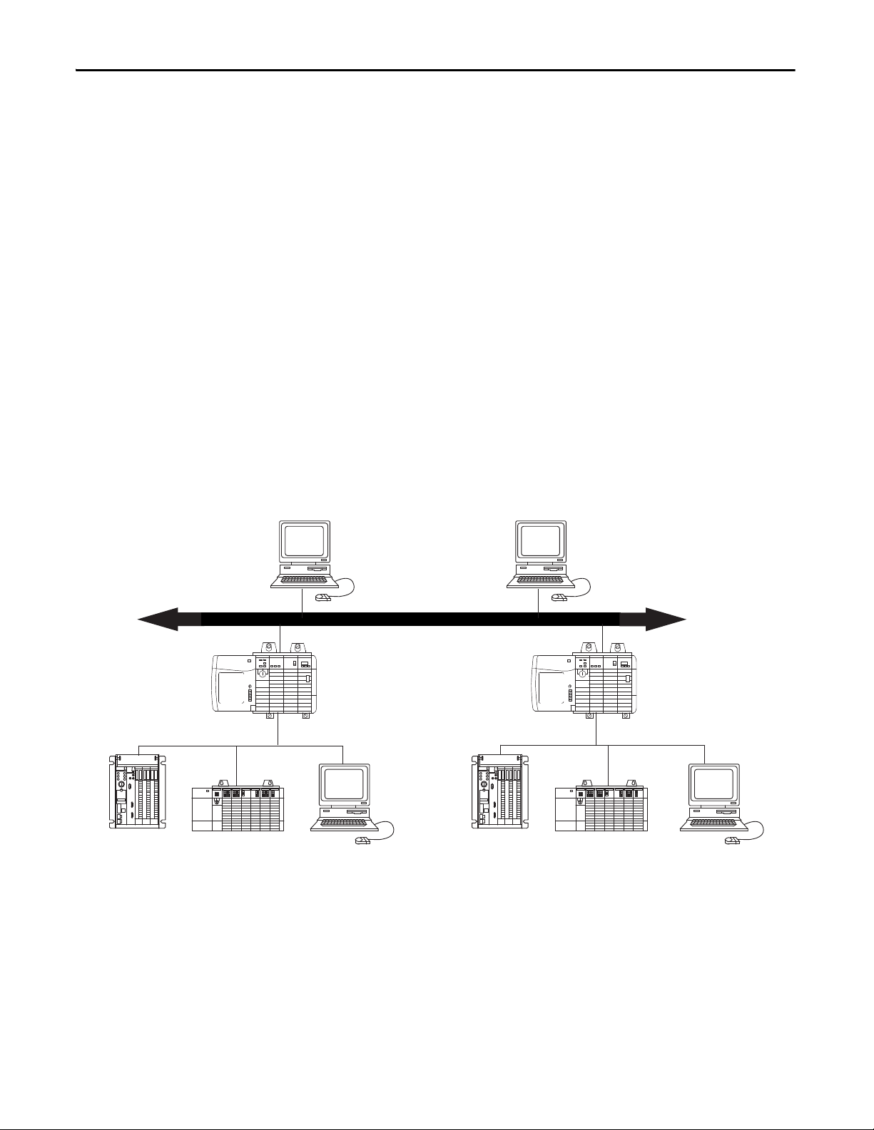
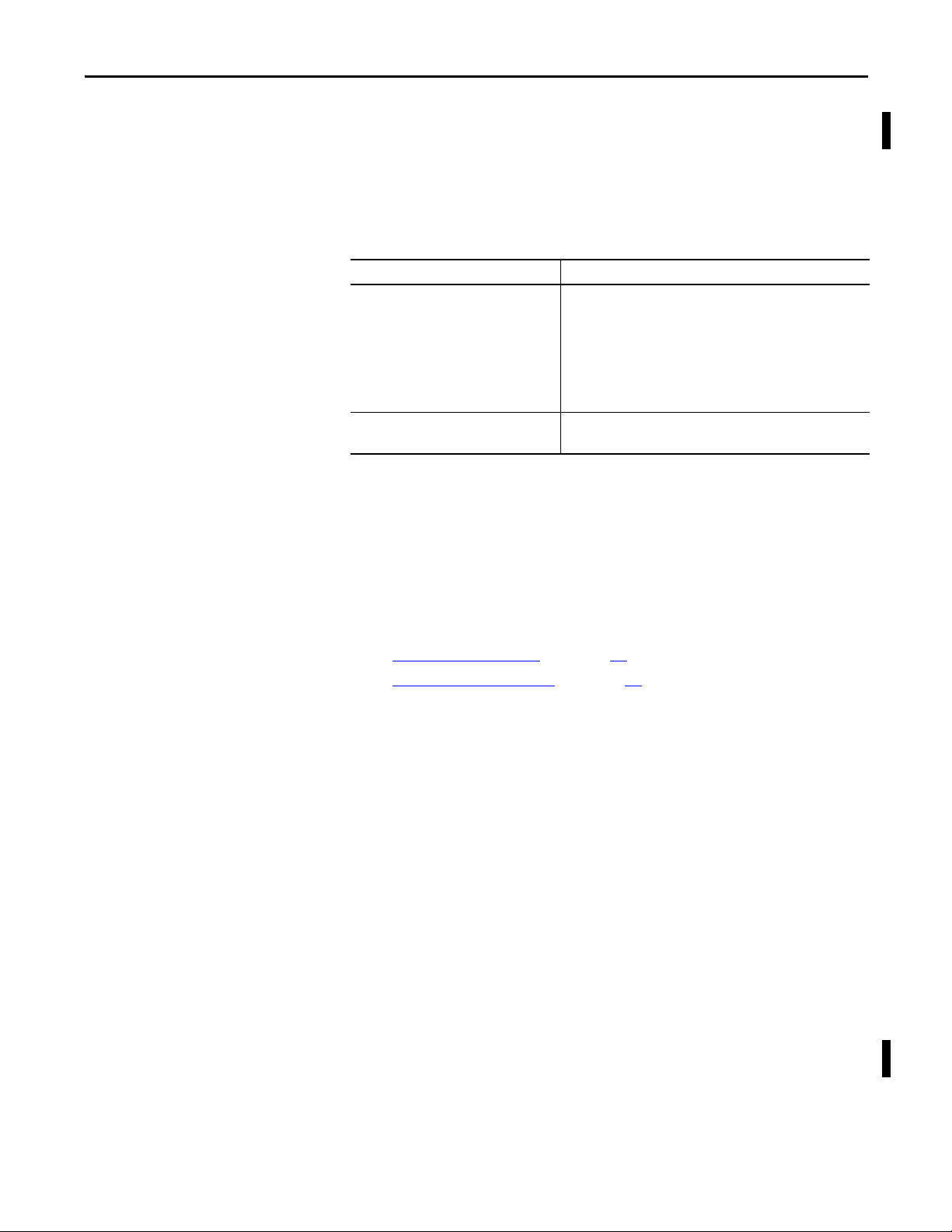
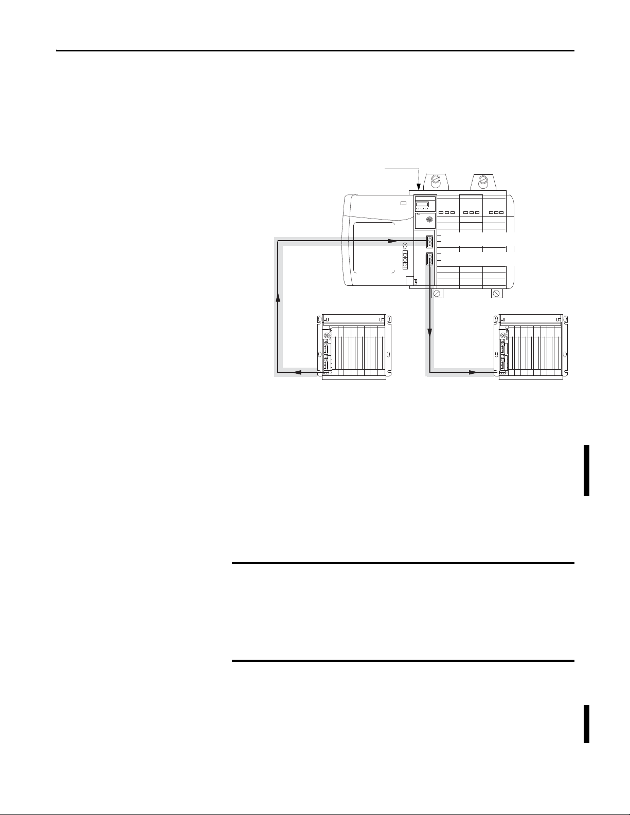
Routing Limitations
The modules can route a message through as many as four communication
networks and three chassis. This limit applies to only the routing of a message
and not to the total number of networks or chassis in a system.
DH+ and CIP Messaging
The modules allow an information exchange between devices, such as
ControlLogix controllers, PLC and SLC controllers.
With these modules, you can exchange information in any of the following
scenarios:
• Between PLC or SLC controllers on different networks
• Between the ControlLogix controllers and a PLC or SLC controller on
different networks
• Between ControlLogix controllers on different networks
The figure shows an example system. Two ControlLogix chassis link Data
Highway Plus networks. Communication between PLC-5® programmable
controllers on different networks is accomplished in the same manner used for
communication within a network.
14 Rockwell Automation Publication 1756-UM514C-EN-P - June 2014
Page 15
About the Module Chapter 1
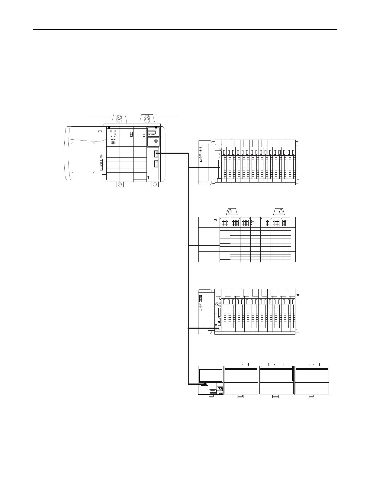
41276
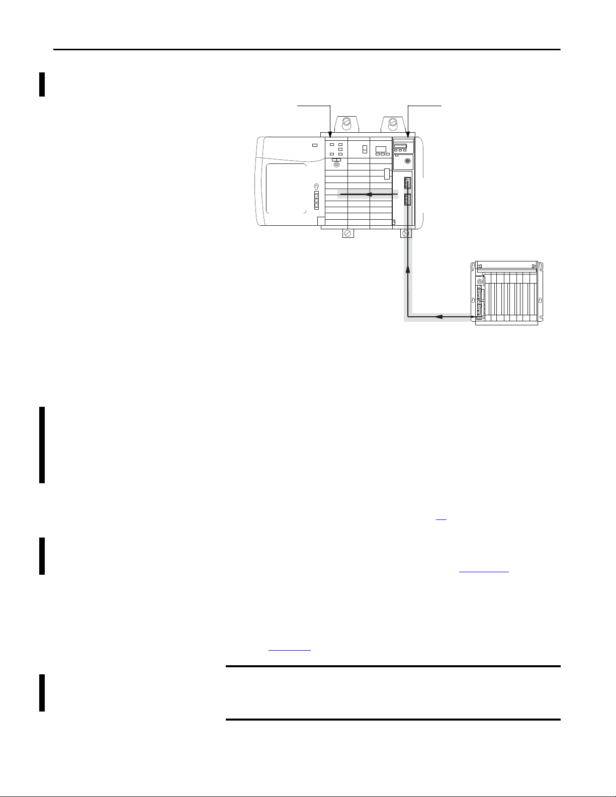
Control Logix
Chassis
1756-DHRIOControlLogix Controller
1771-ASB
1746-ASB
PLC-5/20 in Adapter Mode
1794-FLEX I/O
Remote I/O
Remote I/O
When a channel on the module is configured for Remote I/O, the module acts as
a scanner for the remote I/O network. The ControlLogix controller
communicates to the module’s remote I/O scanner to send and receive the I/O
on the remote I/O network.
The figure shows an example system.
Rockwell Automation Publication 1756-UM514C-EN-P - June 2014 15
Page 16
Chapter 1 About the Module
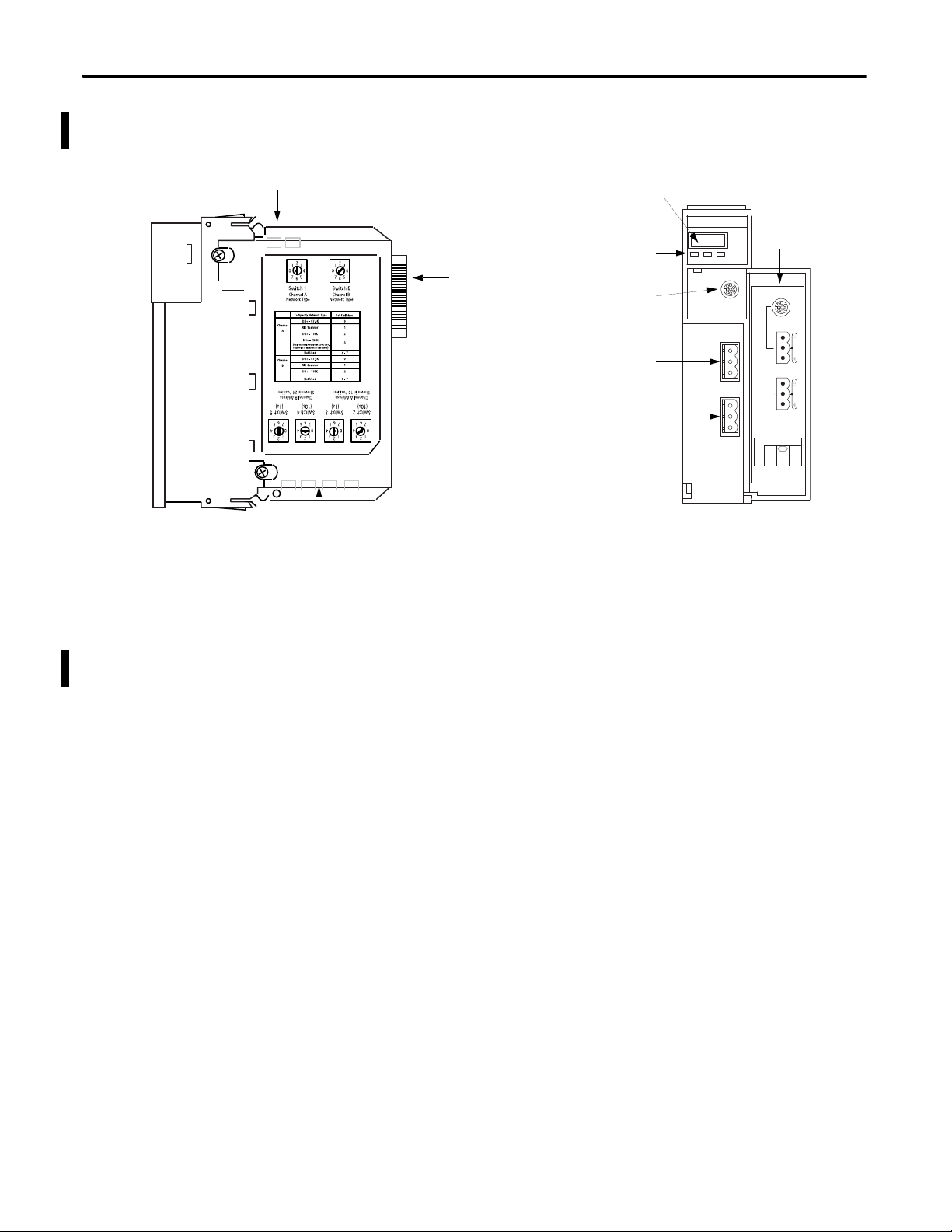
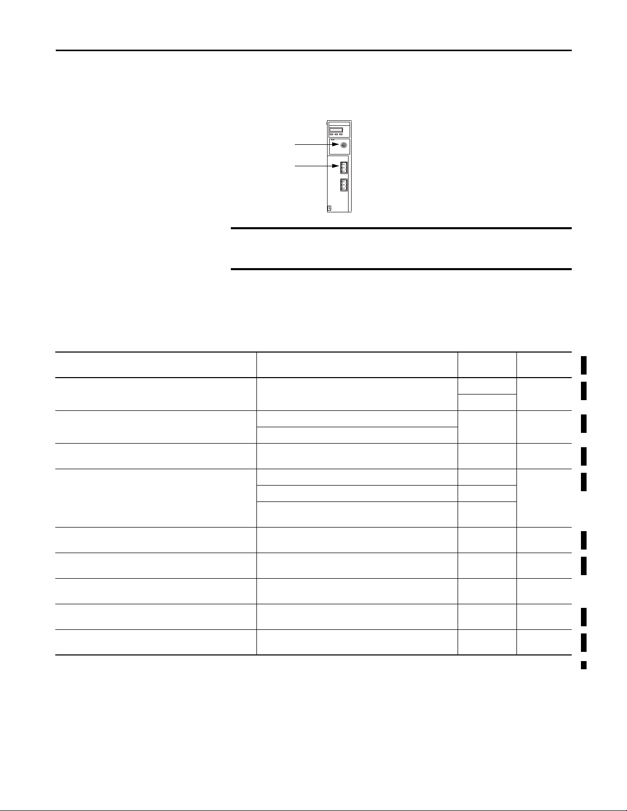
41278
Network Type switches
(behind cover)
41277
Network Address switches
(behind cover)
Backplane
connector
(CIP=Port 1 )
Side
view
Front
view
Alphanumeric
status indicator
Channel and
module status
indicators
8-pin Mini-DIN
Programming
Ter m i na l
Channel A
(CIP=Port 2)
Wirin g
label
Door
Channel B
(CIP=Port 3)
Module Features
The figure shows the external features of the 1756-DHRIO and
1756-DHRIOXT modules.
Other module features include the following:
• Routing table that enables DH+ devices to use the modules and
ControlLogix chassis to access other networks
• Routing communication to and from other modules
• No limit on number of modules per chassis, to the total number of
available slots and the capabilities of the power supply
• Can be removed and inserted under power without disrupting power to
other modules in the chassis
16 Rockwell Automation Publication 1756-UM514C-EN-P - June 2014
Page 17
About the Module Chapter 1
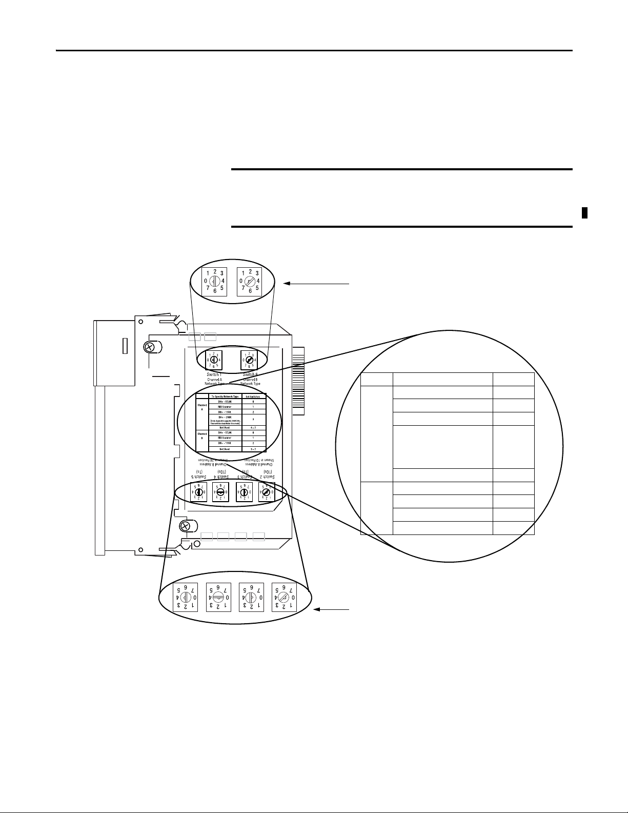
IMPORTANT
Network type
switches (behind
cover)
20810
Node type
switches (behind
cover)
This example shows channel A
set for DH+ and channel B set
RIO
This example shows the channel A node
address at 010 and channel B at 024
Specify Network Type Set Switch
Channel
A
DH+ - 57.6K 0
RIO Scanner 1
DH+ - 115K 2
DH+ - 230K
(Only channel A suppor ts 230K
DH+. Channel B is disabled in this
mode.)
3
Not used 4-7
Channel
B
DH+ - 57.6K 0
RIO Scanner 1
DH+ - 115K 2
Not used 3-7
These node switches are not used with RIO.
Configure Switches
Before installing the module, you must set the network type switches for DH+ or
RIO, depending on your application. For a channel configured as DH+, you
must also select a node address within the range of 00-77. Node addresses are set
and displayed in octal.
If your module uses the 230k DH+ network (that is Channel A switch set to
3), Channel B is disabled.
Also, node address switches do not apply if you are using remote I/O.
Set the network type and node address switches as shown in the Figure.
Rockwell Automation Publication 1756-UM514C-EN-P - June 2014 17
Page 18
Chapter 1 About the Module
CHA
CHB OK
H+/RIO
Alphanumeric status indicator illuminates and cycles through a
sequence of messages (described in the table on the following page).
43241
EXAMPLE
Alphanumeric Indicators
At power-up the module’s alphanumeric display begins a cycle through the
following sequences.
• Channel A and the network used for channel A - DH+ or RIO
• Channel A node address, if used for DH+
• Channel A status
• Channel B and the network used for channel B - DH+ or RIO
• Channel B node address, if used for DH+
• Channel B status
This sequence runs continuously during normal module operation.
For example, if your module uses the following:
• Channel A for DH+ with node address 14
• Channel B for RIO
and the channels are operating properly, you see the following sequence:
• A DH, A#14, A OK, B IO, SCAN, B OK
For a detailed list of the status and error messages that can be displayed across the
alphanumeric indicators, and for troubleshooting information, see Chapter 13
.
18 Rockwell Automation Publication 1756-UM514C-EN-P - June 2014
Page 19
About the Module Chapter 1
Prevent Electrostatic Discharge
Removal and Insertion Under Power
The Data Highway Plus module is sensitive to electrostatic discharge.
ATTENTION: This equipment is sensitive to electrostatic discharge,
which can cause internal damage and affect normal operation. Follow
these guidelines when you handle this equipment:
• Touch a grounded object to discharge potential static.
• Wear an approved grounding wriststrap.
• Do not touch connectors or pins on component boards.
• Do not touch circuit components inside the equipment.
• Use a static-safe workstation, if available.
• Store the equipment in appropriate static-safe packaging when not in
use.
You can install or remove the module while chassis power is applied if you
observe the following precautions.
WARNING: When you insert or remove the module while backplane
power is on, an electrical arc can occur. This could cause an explosion in
hazardous location installations. Be sure that power is removed or the
area is nonhazardous before proceeding.
Repeated electrical arcing causes excessive wear to contacts on the module and its
mating connector. Worn contacts can create electrical resistance that can affect
module operation.
Rockwell Automation Publication 1756-UM514C-EN-P - June 2014 19
Page 20

Chapter 1 About the Module
Notes:
20 Rockwell Automation Publication 1756-UM514C-EN-P - June 2014
Page 21
Chapter
Using the Data Highway Plus Network
This chapter describes the basics of Data Highway Plus (DH+) and the
operation of a DH+ network.
Top ic Pag e
What Is Data Highway Plus? 21
Connect Devices to the DH+ Network 23
Two Methods of Communication Over a DH+ Network 25
Use DH+ Messaging 25
Configuration Information in DH+ Messaging 32
Application Timeout 33
Example DH+ Routing Configuration 34
Use Control and Information Protocol (CIP) Messaging 35
2
What Is Data Highway Plus?
On the most basic level, Data Highway Plus is a wire or cable and a protocol that
connects computers and peripheral devices so that they can communicate. The
wire used for a network is called the network medium.
A DH+ link transfers data between ControlLogix controllers, PLC and SLC
controllers, and other devices that use the DH+ network. These devices are
called stations. You can connect a maximum of 32 stations to one DH+ link.
Rockwell Automation Publication 1756-UM514C-EN-P - June 2014 21
Page 22
Chapter 2 Using the Data Highway Plus Network
IMPORTANT
Link Design
When you design your DH+ link, use good design practices, including laying out
the link before installation. We also recommend you consider the following when
designing your DH+ link:
• All performance requirements
• Maintenance
• Possible future changes to the link
Use a1770-CD (Belden 9463) cable to connect your 1756-DHRIO module to
DH+. Use a Belden 89463 cable to connect your 1756-DHRIOXT module to
DH+. Connect a DH+ network by using a daisy chain or trunk line/drop line
configuration.
Trunk Line/Drop Line Considerations
When using a trunk line/drop line configuration, use 1770-SC station
connectors and follow these cable-length guidelines:
• trunk line-cable length - depends on the communication rate of the link
• drop-cable length - 30.4 m (100 cable-ft.)
Verify that your system’s design plans specify cable lengths within allowable
measurements.
The maximum cable length for DH+ depends on the transmission rate.
Configure all devices on a DH+ link to communicate at the same
transmission rate.
For daisy chain configurations, use the following table to determine the available
total cable length.
A DH+ link using this communication rate: Cannot exceed this cable length:
57.6 kbps 3,048m (10,000 ft)
115.2 kbps 1524m (5,000ft)
230.4 kbps 762m (2,500 ft)
For proper operation, terminate the ends of a DH+ link by using the external
resistors shipped with the module. The following table lists the resistors you can
use with each communication rate.
If your DH+ I/O link operates at: Use this resistor rating:
57.6 kbps 150 Ω
115.2 kbps 150 Ω
230 kbps 82 Ω
22 Rockwell Automation Publication 1756-UM514C-EN-P - June 2014
Page 23
Using the Data Highway Plus Network Chapter 2
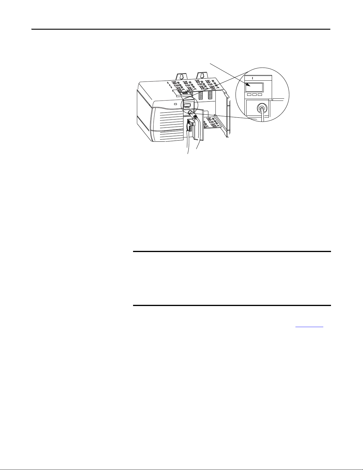
41279
Programming Terminal Connector
Channel A
IMPORTANT
Programming Terminal Port
The programming terminal connector is the same physical link as Channel A.
When configuring the module switches, remember the programming
terminal connector can be used only if Channel A is set for DH+.
Connect Devices to the DH+
The following table lists the devices you can connect to a DH+ link.
Network
To: You can use: Cat. No.: Required
Connect PLC-3 family processors to DH+ Scanner Communication Adapter Module 1775-S5 1770-CD or
1775-SR5
Connect PLC-5 family processors to DH+ Classic and Enhanced PLC-5 processors using on-board DH+ ports 1785-Series 1770-CD or
ControlNet and EtherNet PLC-5 processors using on-board DH+ ports
Connect SLCs to DH+ SLC 5/04 Controller 1747-Series 1770-CD or
Connect PI systems to DH+ Resource Manager Module 5130-RM1 1770-CD or
Resource Manager Module 5130-RM2
Data Highway/Data Highway Plus
Communication Interface Module
Perform data transmission, management, and local network
diagnostics over DH+ network
Perform data transmission, management, and local network
diagnostics over DH+ network
Add memory, storage, and I/O capabilities to computers through
DH+
Connect other SLC controllers to DH+ SLC 5/04 1747-Series 1770-CD or
Connect AutoMax to DH+ AutoMax DH+ Interface 57C-442 1770-CD or
KTX Communication Interface Card 1784-KTX 1770-CD or
KTXD Communication Interface Card 1784-KTXD 1770-CD or
PCMK Communication Card 1784-PCMK PCM6/B cable
5130-KA
Cables
Belden 89463
Belden 89463
Belden 89463
Belden 89463
Belden 89463
Belden 89463
assembly
Belden 89463
Belden 89463
(1)
:
(1) Use 1770-CD for 1756-DHRIO modules and Belden 89463 for 1756- DHRIOXT modules.
Rockwell Automation Publication 1756-UM514C-EN-P - June 2014 23
Page 24

Chapter 2 Using the Data Highway Plus Network
Application Guidelines
Consider the following application guidelines when configuring a DH+ link for
your system:
• Minimize the number of DH+ nodes to achieve acceptable response times.
Keep in mind the size and frequency of messages exchanged between
devices.
• Limit the number of stations on your network when you are trying to
achieve the fastest control response time. Establish separate DH+
networks to bring-on additional stations.
• Do not add or remove stations from the network during machine or
process operation. If the network token resides with a device that is
removed, the token can be lost to the rest of the network. The network is
automatically reestablished, but it could take several seconds. Control is
unreliable or interrupted during this time.
• When possible, do not program controllers online during machine or
process operation. This could result in long bursts of DH+ activity,
increasing response time.
• When possible, add a separate DH+ link for programming processors to
keep effects of the programming terminal from the process DH+ link.
24 Rockwell Automation Publication 1756-UM514C-EN-P - June 2014
Page 25
Using the Data Highway Plus Network Chapter 2
Two Methods of Communication Over a DH+ Network
Use DH+ Messaging
The 1756-DHRIO and 1756-DHRIOXT modules act as a bridge for two
methods of communication. These methods are:
• DH+ Messaging
• Control and Information Protocol (CIP) Messaging
The following table lists the devices that support each communication method.
Type of communication: Devices and Software supporting this type:
DH+ messaging PLC-3
PLC-5
PLC-5/250
SLC 500
ControlLogix controllers
RSLinx software
Interchange software
Control and Information Protocol
(CIP) messaging
ControlLogix controller
Studio 5000 environment
DH+ Messaging offers the following benefits:
• You can send messages between devices on the same link.
• You can send messages between devices on different links.
• It is compatible with many Rockwell Automation® modules.
DH+ messaging is divided into two types:
• Local DH+ Messaging
- See page 25
• Remote DH+ Messaging - See page 28
Before you can design a control system to meet your application needs, be aware
of the difference between Local DH+ Messaging and Remote DH+ Messaging.
Local DH+ Messaging
Devices use local DH+ messaging to communicate between devices on the same
physical link. A device that uses local DH+ messaging must:
• generate local DH+ packets.
• support local DH+ protocol.
• send and receive messages.
A local DH+ message sent on a DH+ network has only enough address
information to get the message to a target node on the same DH+ network.
The example in the following figure shows a PLC-5 controller sending a message
to port A on the 1756-DHRIO and 1756-DHRIOXT modules. Because the
Rockwell Automation Publication 1756-UM514C-EN-P - June 2014 25
Page 26
Chapter 2 Using the Data Highway Plus Network
1756- DHRIO
PLC-5 Controller B
Node Number: 025
Channel A
Node Number: 010
Controller Slot= 0
ControlLogix Controller
41458
IMPORTANT
controller slot for port A is configured to “0”, the message is forwarded to the
ControlLogix controller in slot 0.
Receiving Local DH+ Messages on DH+
Because a local DH+ message has only enough address information to get the
message to a target node on the same DH+ network, the 1756-DHRIO and
1756-DHRIOXT modules that receive this message cannot identify where to
send the message. The 1756-DHRIO and 1756-DHRIOXT modules use the
Controller Slot configuration parameter to send the message to the local
controller.
You must use RSLinx software to configure the controller slot. For more
information on setting the controller slot, see page 51
Some messages, called PCCC commands, are not sent to the controller slot. In
this case, the 1756-DHRIO and 1756-DHRIOXT modules generate a response
to the message. For a complete list of these messages, see Appendix
Local DH+ messaging does not require a populated routing table. Local DH+
messaging does require a default (that is a properly emptied) or an applied (that is
a properly populated and saved) routing table, and a default or applied controller
slot for each channel configured for DH+. For more information on routing
tables, see Chapter 3
,
.
B.
Local DH+ Messaging can target only one ControlLogix controller per DH+
channel. The ControlLogix controller must reside in the same chassis as the
1756-DHRIO and 1756-DHRIOXT modules receiving the message.
26 Rockwell Automation Publication 1756-UM514C-EN-P - June 2014
Page 27

Using the Data Highway Plus Network Chapter 2
IMPORTANT
Sending Local DH+ Messages on DH+
If a 1756-DHRIO channel receives a DH+ message with a destination link ID=0
from a ControlLogix controller in the same chassis, the module sends the
message as a local DH+ message.
The target of the DH+ message must be on the same DH+ link as the 1756DHRIO and 1756-DHRIOXT modules sending the message. Also, the
ControlLogix controller must reside in the same chassis as the 1756-DHRIO
and 1756-DHRIOXT modules sending the message on DH+.
Limitations of Local DH+ Messaging
When using Local DH+ Messaging, you must remember:
• The DH+ message contains only a node ID for a node on the DH+
network.
• A local DH+ message sent to the node ID of a port on the 1756-DHRIO
and 1756-DHRIOXT modules is forwarded to one user-configured
controller slot.
• Messages on one DH+ network cannot be routed to other networks.
Routing Error in Local DH+ Messaging
If the module has a problem with routing a DH+ message, it can return a
response with an error status of D0 hex. A PLC-5 displays this error as D000 hex
when monitoring the message instruction. If you receive this error message,
perform the following actions:
• Check your message instruction to make sure a destination node was
entered.
• Check your default slot configuration to make sure that it matches the
location of the ControlLogix controller in the chassis.
• Make sure power is applied to the module.
Programming Message Block Instructions in a Controller for Local DH+ Messaging
Before programming your message block instructions in your controller, you
must:
• Determine which links send and receive DH+ Local messages.
• Draw a network to make sure you meet the design requirements for Local
DH+ messages.
Rockwell Automation Publication 1756-UM514C-EN-P - June 2014 27
Page 28

Chapter 2 Using the Data Highway Plus Network
IMPORTANT
• Assign DH+ node numbers.
• Use the Studio 5000 environment to enter the controller slot or execute
the default for the controller slot for each channel configured for DH+.
These configuration steps must be done for each 1756-DHRIO or
1756-DHRIOXT in the your system.
Remote DH+ Messaging
Devices use remote DH+ messaging to communicate between devices on
physically separate networks. A device that uses remote DH+ messaging must be
able to perform the following:
• Generate Remote DH+ packets.
• Support Remote DH+ protocol.
• Send and receive messages.
Use remote DH+ messaging when the following conditions apply:
• The message originating device or the message target device is one of the
devices listed in the table on page 25
.
• A DH+ link is in the message’s path from originator to target.
• The message originating device and the message target device are on
separate networks or the message target is in a ControlLogix chassis and
multiple ControlLogix controller targets are in the chassis.
28 Rockwell Automation Publication 1756-UM514C-EN-P - June 2014
Page 29
Using the Data Highway Plus Network Chapter 2
ControlLogix Chassis
1756-DHRIO and 1756-DHRIOXT Modules
PLC-5/25 Controller A - Node:010
Link ID 1
PLC-5 Controller B - Node: 030
41363
Link ID 2
Channel A - Node: 020
Channel B - Node: 025
IMPORTANT
The following figure shows an example of remote DH+ messaging between PLC
processor A and PLC processor B. In this example, the following information
must be included in the remote DH+ message routing message instruction:
• local DH+ node = 020
• destination link ID = 2
• remote DH+ node = 030
Link IDs
To use remote DH+ messaging, each network that is an originating network or
target network requires a unique link ID. The modules require these link IDs to
be decimal values between 1-199. Each DH+ channel on a 1756-DHRIO or
1756-DHRIOXT module requires its own unique link ID.
The message originates on the source network. The destination network is the
message’s target network. This applies to all source and destination networks,
including DH+, ControlNet, Ethernet and a ControlLogix chassis.
For remote DH+ messaging, the ControlLogix chassis is considered a
separate, independent network. Therefore, a system of 1 DH+ network and
one ControlLogix chassis is a two-link system.
The ControlLogix chassis is required to be a separate, independent link for
DH+ messaging if multiple message target ControlLogix controllers are in a
ControlLogix chassis.
Routing Tables in Remote DH+ Messaging
The modules contain a routing table that you define for your application. The
routing table contains information used to steer remote DH+ messages through
the system to ‘remote’ nodes on separate networks. By using the routing table, the
Rockwell Automation Publication 1756-UM514C-EN-P - June 2014 29
Page 30

Chapter 2 Using the Data Highway Plus Network
1756-DHRIO and 1756-DHRIOXT modules enable devices, such as PLC-5s,
to use “DH+ Remote Addressing” for messaging.
You must use RSLinx to configure your routing table. For more information on
routing tables, see page 46
Programming Message Block Instructions in a Controller for Remote DH+ Messaging
Before programming your message block instructions in your controller, you
must perform the following:
• Determine which links will send and receive remote DH++ messaging.
• Draw a network to make sure you meet the design requirements for remote
DH+ messaging.
If you are using remote DH+ messaging, you must also perform the following:
• Assign link numbers. The numbers must be a decimal value between 1-
199. ControlLogix chassis can also be assigned link IDs. Remember that
the programming terminal and channel A are the same physical link.
• Assign DH+ node numbers.
• Use RSLinx software to load routing tables into each 1756-DHRIO and
1756-DHRIOXT module.
When using remote DH+ messaging, you must include the following in the
message instruction:
• Destination link ID - A user-defined number representing a network in
your system.
• Remote node or slot - The node or slot on the remote network with which
you want to communicate.
If the message originates on DH+, you must also include:
• local DH+ node - The node on your local DH+ network capable of
routing the message.
If the message originates on Ethernet or ControlNet networks or ControlLogix
controllers, you must also include a CIP path to the first 1756-DHRIO and
1756-DHRIOXT modules.
Limitations of Remote DH+ Messaging
Remote DH+ Messages are encapsulated in CIP messages and sent on CIP
connections when they are sent across ControlNet, Ethernet, and the
ControlLogix chassis backplane. Resource limits are associated with CIP on the
30 Rockwell Automation Publication 1756-UM514C-EN-P - June 2014
Page 31

Using the Data Highway Plus Network Chapter 2
1756-DHRIO and 1756-DHRIOXT modules, although this is transparent to
the user.
The 1756-DHRIO and 1756-DHRIOXT modules support a total of 32 CIP
connections per DH+ channel. These connections are made when devices want
to send a DH+ message out of a 1756-DHRIO or 1756-DHRIOXT module’s
DH+ channel and are made by the 1756-DHRIO or 1756-DHRIOXT module
when it receives DH+ message traffic. The 1756-DHRIO and 1756DHRIOXT modules recover connections if they are not being used.
Because of the various paths involved, the 1756-DHRIO and 1756-DHRIOXT
modules respond to ‘out of connections’ in one of the following ways:
• The 1756-DHRIO and 1756-DHRIOXT modules can generate a
Routing Error on DH+ for DH+ message requests if no connections are
available.
• The Message Originator can generate an Application Timeout if a remote
1756-DHRIO or 1756-DHRIOXT module has no connections available
for a DH+ Message response.
• The Message Originator can receive an ‘out of connections’ error if the
path from the Originator to the 1756-DHRIO or 1756-DHRIOXT
module is ControlLogix chassis, ControlNet or Ethernet.
Routing Errors in Remote DH+ Messaging
If the 1756-DHRIO and 1756-DHRIOXT modules have a problem with
routing a Remote DH+ Message, they can return a response with an error status
of D0 hex. A PLC-5 displays this error as D000 hex when monitoring the
message instruction. If you receive this error message, perform the following
actions:
• Check your message instruction to make sure a gateway node, link ID and
destination node were entered.
• Check your routing table in each DH+ module that the message passes
through.
• Make sure all 1756-DHRIO and 1756-DHRIOXT modules are
connected and powered-up.
Rockwell Automation Publication 1756-UM514C-EN-P - June 2014 31
Page 32

Chapter 2 Using the Data Highway Plus Network
IMPORTANT
Configuration Information in DH+ Messaging
When you are using DH+ messaging, you must use the default configuration or
write configuration for your application.
The following configuration information is stored in the nonvolatile (NVS)
memory on your 1756-DHRIO and 1756-DHRIOXT modules when you apply
configuration by using the Studio 5000 environment:
• Any routing table that can be needed to send DH+ messages through the
module. - This information must be applied to the module’s configuration
separately from other information. Use RSLinx to apply the routing table.
For more information on routing tables, see page49
• Controller slot for each DH+ channel - This information must be applied
to the module’s configuration separately from other information. For more
information on setting the controller slot, see page 51
• Slot number of the module
• Chassis serial number
If you restore defaults with Studio 5000 environment, the slot number and
chassis serial number are stored in the 1756-DHRIO and 1756-DHRIOXT
module’s nonvolatile memory, but no routing table is used and the
controller slot for the DH+ channels is set to 0.
.
.
Generate Configuration Faults
When you insert a 1756-DHRIO or 1756-DHRIOXT module in a
ControlLogix chassis, the configuration information stored in the module’s NVS
memory is compared to the slot and serial number of the chassis it is entering. If
any information does not match, the 1756-DHRIO or1756-DHRIOXT
module generates a configuration fault.
For a complete listing of the configuration faults that can be displayed on your
1756-DHRIO and 1756-DHRIOXT modules, see Chapter 13
.
32 Rockwell Automation Publication 1756-UM514C-EN-P - June 2014
Page 33

Using the Data Highway Plus Network Chapter 2
ControlLogix Chassis
19770
Routed messages sent over
the backplane.
1756-DHRIO
PLC-5/25 Controller
1756-DHRIO
PLC-5/40 Controller
DH+ Link 1
DH+ Link 2
PLC-5/40 detects an
application timeout
and increments the
error count.
PLC-5/25’s controllers
are full.
Application Timeout
When an error occurs while sending a message to a remote link, it appears to the
sending station as an application timeout because error messages are not routed
back. When an error occurs during routing, it can be dropped.
For example, if a PLC 5/40 processor sends a message to a PLC processor, and
the PLC-5/25 processor’s buffers are full, three things happen:
• The PLC-5/25 processor refuses the message because the buffers are full.
• When no reply is received, the originator detects an application timeout.
• The originator increments its error count.
The PLC-5/40 processor can retry to send the message later. The following
figure shows an example of an application timeout.
Rockwell Automation Publication 1756-UM514C-EN-P - June 2014 33
Page 34

Chapter 2 Using the Data Highway Plus Network
ControlLogix Ch assis
Link ID 6
1756-DHRIO and 1756-DHRIOXT Modules
Ch. A Node: 015
Ch. B Node:016
1756-DHRIO and 1756-DHRIIOXT Modules
Node: 030
Node:031
PLC-5/25 Controller
Node: 020
DH+
Link ID 1
41285
DH+
Link ID 2
ControlNe t
Link ID 3
DH+
Link ID 4
PLC-5/15 Controller
Node: 020
PLC-5/60 Controller
Node:020
PLC-5/40 Controller
Node: 020
PLC-5/25 Controller
Node: 030
DH+
Link ID 5
1756-CNB Module
Node: 20
PLC-5C Controller
Node: 35
PLC-5C Controller
Node: 45
ControlLogix Controller
Slot 0
ControlLogix Controller
Slot 5
IMPORTANT
Example DH+ Routing Configuration
The following figure shows an example DH+ routing configuration.
Node numbers on DH+ are given in octal. Node numbers on ControlNet
network and slot numbers in ControlLogix chassis are given in decimal. Links
IDs for all networks are given in decimal.
Some devices in the figure have the same node number because they are
on different networks. Devices on the same network require unique node
numbers. You must assign the node numbers.
34 Rockwell Automation Publication 1756-UM514C-EN-P - June 2014
Page 35

Using the Data Highway Plus Network Chapter 2
ControlLogix Syste m 1
Node:0 01
ControlLog ix System 2
1756-DHRIOControlLog ix Controller
41289
1756-DHRIO
ControlLogix Controller
Node: 002
IMPORTANT
Use Control and Information Protocol (CIP) Messaging
Control and Information Protocol (CIP) is the communication mechanism on
ControlLogix chassis, ControlNet network and Ethernet with the Encapsulation
Protocol (EPIC) protocol.
Like DH+ messaging, CIP supports communication between devices on the
same link and physically separate links. However, CIP Messaging uses another
method to route messages than DH+ Messaging.
CIP uses a “relative path” concept for routing messaging. Because the message
itself, or the connection the message is sent on, contains the information required
to route the message, CIP messages do not require any routing table or link IDs.
For more information on paths, see Chapter 4
.
Devices such as ControlLogix devices, devices that use the ControlNet network,
and devices that use EPIC protocol on Ethernet support this new type of
communication.
Your 1756-DHRIO and 1756-DHRIOXT modules support bridging CIP
messaging over a DH+ link. However, your 1756-DHRIO and 1756-DHRIOXT
modules do not support bridging CIP I/O data from a ControlLogix
controller to a 1756-I/O module.
The message originator, target, and all modules and links between them
must support CIP to send a message by using CIP protocol.
Limitations of CIP Messaging
The 1756-DHRIO and 1756-DHRIOXT modules support 32 connections per
DH+ channel. A total of 5 of the connections can be CIP connections. These 5
count against the 32 connections. So if a 1756-DHRIO or 1756-DHRIOXT
module used 30 connections for DH+ Message Routing, it can use only 2
connections to bridge a CIP message through the module on that channel.
Rockwell Automation Publication 1756-UM514C-EN-P - June 2014 35
Page 36

Chapter 2 Using the Data Highway Plus Network
Notes:
36 Rockwell Automation Publication 1756-UM514C-EN-P - June 2014
Page 37

Chapter
3
Installing the Modules
Top ic Pag e
Before You Begin 40
Install the Module 41
Wire the Module 42
Network Connectors and Cable 43
You can install or remove the module while chassis power is applied.
ATTENTION: Environment and Enclosure
This equipment is intended for use in a Pollution Degree 2 industrial environment, in overvoltage Category II applications (as
defined in IEC 60664-1), at altitudes up to 2000 m (6562 ft) without derating.
This equipment is not intended for use in residential environments and may not provide adequate protection to radio
communication services in such environments.
This equipment is supplied as open-type equipment. It must be mounted within an enclosure that is suitably designed for those
specific environmental conditions that will be present and appropriately designed to prevent personal injury resulting from
accessibility to live parts. The enclosure must have suitable flame-retardant properties to prevent or minimize the spread of flame,
complying with a flame spread rating of 5VA or be approved for the application if nonmetallic. The interior of the enclosure must be
accessible only by the use of a tool. Subsequent sections of this publication may contain additional information regarding specific
enclosure type ratings that are required to comply with certain product safety certifications.
In addition to this publication, see the following:
• Industrial Automation Wiring and Grounding Guidelines, publication 1770-4.1
• NEMA 250 and IEC 60529, as applicable, for explanations of the degrees of protection provided by enclosures.
, for additional installation requirements.
Rockwell Automation Publication 1756-UM514C-EN-P - June 2014 37
Page 38

Chapter 3 Installing the Modules
North American Hazardous Location Approval
The following information applies when operating this equipment in
hazardous locations.
Produc ts marked "CL I, DIV 2, GP A, B, C, D" are suitable for use in Class
I Division 2 Groups A, B, C, D, Hazardous Locations and nonhazardous
locations only. Each product is supplied with markings on the rating
nameplate indicating the hazardous location temperature code.
When combining products within a system, the most adverse
temperature code (lowest "T" number) may be used to help
determine the overall temperature code of the system. Combinations
of equipment in your system are subject to investigation by the local
Authority Having Jurisdiction at the time of installation.
WARNING: EXPLOSION HAZARD -
• Do not disconnect equipment unless power has
been removed or the area is known to be
nonhazardous.
• Do not disconnect connections to this equipment
unless power has been removed or the area is
known to be nonhazardous. Secure any external
connections that mate to this equipment by using
screws, sliding latches, threaded connectors, or
other means provided with this product.
• Substitution of components may impair suitability
for Class I, Division 2.
• If this product contains batteries, they must only
be changed in an area known to be nonhazardous.
Informations sur l’utilisation de cet équipement en environnements
dangereux.
Les produits marqués "CL I, DIV 2, GP A, B, C, D" ne conviennent qu'à
une utilisation en environnements de Classe I Division 2 Groupes A, B,
C, D dangereux et non dangereux. Chaque produit est livré avec des
marquages sur sa plaque d'identification qui indiquent le code de
température pour les environnements dangereux. Lorsque plusieurs
produits sont combinés dans un système, le code de température le
plus défavorable (code de température le plus faible) peut être utilisé
pour déterminer le code de température global du système. Les
combinaisons d'équipements dans le système sont sujettes à
inspection par les autorités locales qualifiées au moment de
l'installation.
AVERTISSEMENT: RISQUE D’EXPLOSION –
• Couper le courant ou s'assurer que
l'environnement est classé non dangereux avant
de débrancher l'équipement.
• Couper le courant ou s'assurer que
l'environnement est classé non dangereux avant
de débrancher les connecteurs. Fixer tous les
connecteurs externes reliés à cet équipement à
l'aide de vis, loquets coulissants, connecteurs
filetés ou autres moyens fournis avec ce produit.
• La substitution de composants peut rendre cet
équipement inadapté à une utilisation en
environnement de Classe I, Division 2.
• S'assurer que l'environnement est classé non
dangereux avant de changer les piles.
38 Rockwell Automation Publication 1756-UM514C-EN-P - June 2014
Page 39

Installing the Modules Chapter 3
European Hazardous Location Approval
The following applies when the product bears the Ex Marking.
This equipment is intended for use in potentially explosive atmospheres as defined by European Union Directive 94/9/EC and has been found to
comply with the Essential Health and Safety Requirements relating to the design and construction of Category 3 equipment intended for use in
Zone 2 potentially explosive atmospheres, given in Annex II to this Directive.
Compliance with the Essential Health and Safety Requirements has been assured by compliance with EN 60079-15 and EN 60079-0.
ATTENTION: This equipment is not resistant to sunlight or other sources of UV radiation.
WARNING:
• This equipment shall be mounted in an ATEX-certified enclosure with a minimum ingress protection rating of at least IP54 (as
defined in EN 60529) and used in an environment of not more than Pollution Degree 2 (as defined in EN 60664-1) when
applied in Zone 2 environments. The enclosure must have a tool-removable cover or door.
• This equipment shall be used within its specified ratings defined by Rockwell Automation.
• Provision shall be made to prevent the rated voltage from being exceeded by transient disturbances of more than 140% of the
rated voltage when applied in Zone 2 environments.
• This equipment must only be used with ATEX certified Rockwell Automation backplanes.
• Secure any external connections that mate to this equipment by using screws, sliding latches, threaded connectors, or other
means provided with this product.
• Do not disconnect equipment unless power has been removed or the area is known to be nonhazardous.
ATTENTION: Prevent Electrostatic Discharge
This equipment is sensitive to electrostatic discharge, which can cause internal damage and affect normal operation. Follow these
guidelines when you handle this equipment:
• Touch a grounded object to discharge potential static.
• Wear an approved grounding wriststrap.
• Do not touch connectors or pins on component boards.
• Do not touch circuit components inside the equipment.
• Use a static-safe workstation, if available.
• Store the equipment in appropriate static-safe packaging when not in use.
Rockwell Automation Publication 1756-UM514C-EN-P - June 2014 39
Page 40

Chapter 3 Installing the Modules
Network Type Switches
Backplane
Connector
Alphanumeric Status Indicators
Wiring Label
Front View
Note Address Switches
Side View
Channel
and Module
8-pin Mini-DIN
Programming
Ter m in al
Channel A
Connector
Channel B
Conne ctor
43232
Network Type Switches (behind cover)
This example shows Channel A set for DH+
and Channel B set for RIO.
This example shows Channel A node address at 10
and Channel B node address at 24.
Node Address Switches (behind cover)
43233
Power Supply
Chassis
43234
Before You Begin
Follow these procedures before installing the module.
ATTENTION: If this equipment is used in a manner not specified by the
manufacturer, the protection provided by the equipment may be impaired.
1. Identify the module features, as shown.
40 Rockwell Automation Publication 1756-UM514C-EN-P - June 2014
2. Install and connect a ControlLogix chassis and power supply.
3. Set the network type switches for each channel.
Page 41

Installing the Modules Chapter 3
IMPORTANT
Slot 0
43235
Slot 1
Slot 2
Slot 3
POWER
Circuit Board
43236
If the network type is DH+, you must also set the node address switches
for that channel.
If you are using the remote I/O network, do not set node address switches.
For each channel, you can select a node address within the range of 00…77.
4. Determine module slot location.
This example shows chassis slot numbering in a 4-slot chassis. Slot 0 is the first
slot and is the left most slot in the rack (the first slot to the right of the power
supply). You can use any size ControlLogix chassis and install the module in any
slot.
Install the Module
You can use multiple 1756-DHRIO or 1756-DHRIOXT modules in the same
chassis.
Follow these steps to install the module.
1. Align the circuit board wit the top and bottom guides in the chassis.
2. Slide the module into the chassis.
3. Make sure the module backplane connector properly connects to the
chassis backplane.
If you are replacing a module with an identical one, and you want to resume
identical system operation, you must install the new module in the same slot.
Rockwell Automation Publication 1756-UM514C-EN-P - June 2014 41
Page 42

Chapter 3 Installing the Modules
43238
Wiring Label
Channel A and B
Conne ctors
8-pin Mini-DIN programming
terminal connection parallel to
Channel A when Channel A is
configure for DH+ communication.
43239
Wire the Module
Wire the connectors for the module channels.
WARNING: If you connect or disconnect the communications cable with
power applied to this module or any device on the network, an electrical
arc can occur. This could cause an explosion in hazardous location
installations.
Be sure that power is removed or the area is nonhazardous before
proceeding.
.
Pin Assignments for Channel A and B Connectors
DH+ Remote I/O
Pin Numbers Description Pin Number Description
1Clear1Blue
Shield Shield
Blue 2 Clear
4. Connect the module to the programming terminal and Data Highway
Plus or remote I/O network.
POWER
POWER
WARNING: The local programming terminal port is intended for
temporary use only and must not be connected or disconnected unless
the area is assured to be nonhazardous.
For hazardous locations, use the following Rockwell Automation cable for
the programming terminal connection: 1784-U2DHP.
42 Rockwell Automation Publication 1756-UM514C-EN-P - June 2014
Page 43

5. Apply chassis power.
6. Check power supply and module status.
Installing the Modules Chapter 3
Network Connectors and Cable
The following network connectors and cable are available for the modules.
Parts Requir ements
DH-RIO/DH+ Belden 9463 twinaxial
DH-RIOXT/DH+ Belden 89463 twinaxial
Programming (nonhazardous) 1784-CP
Programming (hazardous) 1784-U2DHP
Rockwell Automation Publication 1756-UM514C-EN-P - June 2014 43
Page 44

Chapter 3 Installing the Modules
Notes:
44 Rockwell Automation Publication 1756-UM514C-EN-P - June 2014
Page 45

Using Programming Software in DH+
Applications
Chapter 4
What This Chapter Contains
Select the Correct Software
This chapter describes how to use programming software with your
1756-DHRIO and 1756-DHRIOXT modules in DH+ applications, including a
brief discussion of how to use each. For more information on these software, see
the online help in each.
Topic: Page
Use RSLinx to Create a Routing Table 46
Use RSLinx Software to Send Control and Information Protocol
Messages
Use RSLogix 5 52
Use RSLogix 500 55
Use the Studio 5000 Environment 58
Define Connection Paths 63
51
The programming software you need is dependent on what products you are
using with the 1756-DHRIO and 1756-DHRIOXT modules. The following
table explains what software is needed for your application.
If you are using this product with the 1756-DHRIO
module to read/write data in a DH+ application:
PLC controllers RSLinx®
SLC controllers RSLinx
ControlLogix controllers RSLinx
You must use this software:
RSLogix 5
RSLogix500
Studio 5000 environment
Rockwell Automation Publication 1756-UM514C-EN-P - June 2014 45
Page 46

Chapter 4 Using Programming Software in DH+ Applications
Use RSLinx to Create a Routing Table
DH+ protocols do not use the Control and Information Protocol (CIP), the
communication protocol used in the ControlLogix architecture. The
1756-DHRIO and 1756-DHRIOXT modules are the transition point from the
DH+ network to ControlLogix. In this capacity, the 1756-DHRIO and
1756-DHRIOXT modules serve as the DH+ message source and require a full
message route, or path, to deliver the message. A routing table, using link IDs and
node addresses, provides the full path.
What Is a Routing Table?
Before you can create a routing table for your 1756-DHRIO and
1756-DHRIOXT modules, you must assign link IDs to all networks (including
ENET and CNET) that route information through the module. Link IDs are
numbers from 1…199.
DH+ module addressing provides the link IDs and node addresses. The routing
table translates link IDs and node address information into path, or routing,
information. Thus, the routing table specifies a 'map' to other links in the system.
Routing tables are configured at each node to build accurate connections.
ControlLogix supports Pyramid Integrator (PI) routing and is backwardcompatible with DH+ products. The architecture also provides newer routing
protocols that are designed to make it easier to maintain a system. The
1756-DHRIO and 1756-DHRIOXT modules, as the transition points between
the ControlLogix architecture and the DH+ network, enable ControlLogix to
use new protocols while maintaining the option of backward-compatibility with
DH+ products.
Pyramid Integrator Emulation
Each Pyramid Integrator chassis has a routing table in it that tells the chassis
where each DH+ link is in relation to that chassis. The routing table uses a link
ID to identify each link. You must enter a port for each link that is local to that
chassis and a bridge address for each link that is remote from that chassis.
Each bridge can have a list of link IDs that are accessible through that bridge. A
bridge can be any device that supports the Pyramid Integrator style of routing,
including the following:
• Pyramid Integrator
• ControlLogix chassis
• WinLinx Gateway
• RSLinx workstation hosting DDE topics or applications that accept
unsolicited messages
46 Rockwell Automation Publication 1756-UM514C-EN-P - June 2014
Page 47

Using Programming Software in DH+ Applications Chapter 4
Pyramid Integrator A Pyramid Integrator B
Data Highway Plus
43341
11 12
Port 2 Port 3 Port 2 Port 3
Link 1 Link 2 Link 3 Link 4
For example, the Pyramid Integrator system shown in the following figure uses
the routing tables described in the following tables.
System A Routing Table
Link ID Module and Port Type Bridge
11KA-2LocalNA
21KA-3LocalNA
32KA-2Remote12
42KA-3Remote12
System B Routing Table
Link ID Module and Port Type Bridge
11KA-2Remote11
21KA-3Remote11
32KA-2LocalNA
42KA-3LocalNA
Rockwell Automation Publication 1756-UM514C-EN-P - June 2014 47
Page 48

Chapter 4 Using Programming Software in DH+ Applications
ControlLogix System A ControlLogix System B
Data Highway Plus
43342
Link 1 Link 2 Link 3 Link 4
ControlLogix System A routing table
in RSLinx software
ControlLogix System B routing
table in RSLinx software
11 12
An equivalent routing (via the DH+ network) with ControlLogix is shown in
the following figure.
ControlLogix Routing
In the ControlLogix system, you complete the same tasks as in Pyramid
Integrator Emulation; however, the presentation is graphical instead of tabular.
The ControlLogix routing protocols use CIP, a message-based protocol that
implements a relative path to send a message from the source device in a system to
the destination device. In this way, the source device in a networks system
contains the path information that steers the message along the proper route to
reach its destination. Because the source device holds this information, other
devices along the path simply pass this information; they do not need to store it.
ControlLogix routing has two significant benefits:
• You do not need to configure routing tables in the bridging module, greatly
simplifying maintenance and module replacement.
• You maintain full control over the route taken by each message, enabling
you to select alternative paths for the same end device.
48 Rockwell Automation Publication 1756-UM514C-EN-P - June 2014
Page 49

Using Programming Software in DH+ Applications Chapter 4
1. Expand the configuration tree until
your application appears on the right
side of the dialog box.
2. Right-click the 1756-DHRIO or 1756DHRIOXT module’s icon to see the
menu.
3. Click Module Configuration.
DHRIO Routing Tab
Create the Routing Table
To create a routing table for your application, follow these steps:
1. Start RSLinx.
2. Browse the network.
3. Use the left-side navigation bar to see your DH+ application, as shown in
the following example.
4. When the 1756-DHRIO Configuration pop-up appears, select the
DHRIO Routing Table tab.
You must use RSLinx software to build the routing table based on the
1756-DHRIO and 1756-DHRIOXT modules in the ControlLogix
chassis. Each link ID (that is chassis backplane, channels A and B of any
1756-DHRIO and 1756-DHRIOXT modules in the chassis) is initially
undefined.
Rockwell Automation Publication 1756-UM514C-EN-P - June 2014 49
Page 50

Chapter 4 Using Programming Software in DH+ Applications
1. Right-click the 1756-DHRIO
module to see the menu.
2. Click Edit Module.
IMPORTANT
Click OK.
Click OK.
5. You must assign link IDs, as shown below.
Keep track of your Link ID assignments. You need the Link ID values when
you send messages via Studio 5000 environment software.
6. To assign a Link ID for the chassis backplane, follow the procedure
described in step 5
. When you are finished assigning Link IDs, your dialog
box will look similar to the one below.
The software prompts you to download routing table changes.
50 Rockwell Automation Publication 1756-UM514C-EN-P - June 2014
Page 51

Using Programming Software in DH+ Applications Chapter 4
1. Change the Controller
slot.
2. Click OK.
43462
PLC-5 Controller
PCCC Messages
1756-ENET Module
Personal Computer Running RSLinx Software
CIP Message
Ethernet
1756-DHRIO Module
1756-DHRIO Module
DH+
CH A
DH+
CIP Message
CH B
When the routing table is downloaded, RSLinx returns to the Browsing screen.
This completes the routing table creation process.
Configure the Controller Slot
The Controller Slot is the physical location of a ControlLogix controller in a
DH+ application. The default setting is slot 0. If necessary, use the Channel
Configuration tab to change the Controller Slot number.
Use RSLinx Software to Send Control and Information Protocol Messages
The 1756-DHRIO and 1756-DHRIOXT modules cannot receive Control and
Information Protocol (CIP) messages on one of its DH+ channels to send the
messages as Programmable Controller Communication Command (PCCC)
messages out of its second DH+ channel.
RSLinx software uses the CIP protocol when it sends messages via Ethernet or
ControlNet networks. Therefore, it cannot route an RSWho message from an
1756-ENET module to one 1756-DHRIO or1756-DHRIOXT module, to
channel A of a second 1756-DHRIO or 1756-DHRIOXT module in a second
chassis, and out of channel B of the second 1756-DHRIO or1756-DHRIOXT
module (see the X in the following figure).
Rockwell Automation Publication 1756-UM514C-EN-P - June 2014 51
Page 52

Chapter 4 Using Programming Software in DH+ Applications
43463
PLC-5 Controller
PCCC Messages
1756-ENET Module
Personal Computer Running RSLinx Software
Ethernet
1756-DHRIO Module
1756-DHRIO Module
DH+
CH A
DH+
CIP Message
CH B
IMPORTANT
Click here to add
a rung.
To do this, use the 1756-ENET module to connect to a second ControlLogix
chassis that contains the second 1756-DHRIO or 1756-DHRIOXT module, as
shown in the following figure.
Use RSLogix 5
RSLogix 5 software is required to send read/write message instructions from
PLC-5s in DH+ applications. To send messages, follow these steps:
This section offers a brief description of how to send a message via
RSLogix 5 software. For a full description of how to use the software, see
the online help.
1. Start the RSLogix 5 software.
2. Begin a new project or open a project.
3. Add a rung to the ladder logic portion of the project.
52 Rockwell Automation Publication 1756-UM514C-EN-P - June 2014
Page 53

Using Programming Software in DH+ Applications Chapter 4
Click here to add
a MSG.
Typ e th e new Con trol
value he re. This
example uses a Control
of MG10:0.
Double-click Setup
Screen to access the
message instruction
dialog box.
4. Add a message instruction (MSG) to the new rung.
5. Change the MSG instruction Control.
6. Configure the MSG instruction on the Setup dialog box.
Rockwell Automation Publication 1756-UM514C-EN-P - June 2014 53
Page 54

Chapter 4 Using Programming Software in DH+ Applications
ControlLogix Chassis
1756-DHRIO
PLC-5/25 controller A
Node Number: 015
DH+ Link
Link ID 1
PLC-5 controller B
Node Number: 025
41363
Channel A
Node Number: 010
Channel B
Node Number: 020
DH+ Link
Link ID 2
Studio 5000 Environment DH+ Application Example
The following figure shows an example DH+ application where PLC-5/25
processor A writes data, via a message instruction and the 1756-DHRIO or
1756-DHRIOXT module, to PLC-5 processor B.
54 Rockwell Automation Publication 1756-UM514C-EN-P - June 2014
Page 55

Using Programming Software in DH+ Applications Chapter 4
IMPORTANT
Click here to add
a rung.
Click here to add
a MSG.
Use RSLogix 500
RSLogix 500 software is required to send read/write message instructions from
SLC-500s in DH+ applications. To send messages, follow these steps:
This section offers a brief description of how to send a message via
RSLogix 500 software. For a full description of how to use the software, see
the online help.
1. Start the RSLogix 500 software.
2. Begin a new project or open a project.
3. Add a rung to the ladder logic portion of the project.
4. Add a message instruction (MSG) to the new rung.
Rockwell Automation Publication 1756-UM514C-EN-P - June 2014 55
Page 56

Chapter 4 Using Programming Software in DH+ Applications
Typ e th e new Con trol
value he re. This
example uses a Control
of N7:20.
Double-click Setup
Screen.
5. Change the MSG instruction Control.
6. Configure the MSG instruction on the Setup dialog box.
56 Rockwell Automation Publication 1756-UM514C-EN-P - June 2014
Page 57

Using Programming Software in DH+ Applications Chapter 4
ControlLogix Chassis
1756-DHRIO
SLC 5/04 controller A
Node Number: 015
DH+ Link
Link ID 1
SLC 5/04 controller B
Node Number: 025
19765
1756-DHRIO
DH+ Link
Link ID 2
Channel B
Node Number: 020
Channel B
Node Number: 030
RSLogix 500 DH+ Application Example
The following figure shows an example DH+ application that includes SLC-5
processors using the 1756-DHRIO and 1756-DHRIOXT modules to write
message instructions.
Rockwell Automation Publication 1756-UM514C-EN-P - June 2014 57
Page 58

Chapter 4 Using Programming Software in DH+ Applications
IMPORTANT
1. Right-click Main Routine to see the
menu.
2. Click Open.
Click the MSG button.
Use the Studio 5000 Environment
The Studio 5000 environment is required to send read/write message
instructions from a ControlLogix controller in DH+ applications. To send
messages, follow these steps:
You are not required to add the 1756-DHRIO or 1756-DHRIOXT module to
the Controller Organizer to send message instructions from a ControlLogix
controller in a DH+ application.
1. Start the Studio 5000 environment.
2. Begin a new project or open a project.
3. Add a message instruction (MSG) to the new rung of ladder logic.
4. Add a message instruction (MSG) to the new ladder logic rung that
appears.
58 Rockwell Automation Publication 1756-UM514C-EN-P - June 2014
Page 59

Using Programming Software in DH+ Applications Chapter 4
1. Right-click the question mark (?) the
menu.
2. Click New Tag.
1. Name the tag.
2. Make sure this tag is of the
MESSAGE type.
Double-click the ellipsis (…) button.
5. Add a new tag to the MSG instruction.
6. Name and define the new tag.
7. Access the message type configuration and communication parameters.
Rockwell Automation Publication 1756-UM514C-EN-P - June 2014 59
Page 60

Chapter 4 Using Programming Software in DH+ Applications
1. Choose the Message Type from the
pull-down list.
2. Choose the Source Element from the
pull-down list if the tag exists.
If the tag does not exist, use the New
Tag feature (shown below) to create
it.
3. Type the Number of Elements being
written.
4. Type the Destination Element. In this
example, the Destination Elemen t is a
PLC-5 data table.
If you create a Tag, you must:
1. Name the tag.
2. Make sure the Data Type is Integer
(INT).
1. Set the path. For DH+ applications, the
number order must match the
ControlLogix chassis backplane (1) and
the slot number of the local 1756-DHRIO
and 1756-DHRIOXT modules.
2. Select the DH+ Communication
Method.
3. Enter the information from the routing
table for this module.
8. Change the message configuration.
9. Set the communication path for the message instruction.
60 Rockwell Automation Publication 1756-UM514C-EN-P - June 2014
Page 61

Using Programming Software in DH+ Applications Chapter 4
1756-DHRIO
PLC-5/60 controller A
Node Number: 015
DH+ Link
41283
Channel A
Node Number: 010
Control Logix Controller
Slot Number: 0
Studio 5000 Environment DH+ Application Example
The following figure shows an example DH+ application that includes a
ControlLogix controller using the 1756-DHRIO and 1756-DHRIOXT
modules to write message instructions.
For this example, you must follow the basic steps described beginning on
page 58
communication parameters will match the ones shown below.
. The message instruction’s ladder logic’s rung and configuration and
Rockwell Automation Publication 1756-UM514C-EN-P - June 2014 61
Page 62

Chapter 4 Using Programming Software in DH+ Applications
Configuration Pop-Up Dialog Box Communication Pop-Up Dialog Box
1 represents the ControlLogix backplane
(as the message leaves the ControlLogix
controller)
3 represents the location of the 1756DHRIO module (that is slot 3)
62 Rockwell Automation Publication 1756-UM514C-EN-P - June 2014
Page 63

Using Programming Software in DH+ Applications Chapter 4
Define Connection Paths
You can configure a connection path when configuring controller-to-controller
communication or workstation-to-controller communication. The connection
path starts with the controller or the communication card in the workstation.
The following steps construct a communication path:
1. Separate the number or address entered in each step with a comma. All
numbers are in decimal by default. You can enter any number, other than
an Ethernet IP address, in another base by using the IEC-1131 prefix
(8# for octal, 16# for hexadecimal). Ethernet IP addresses are decimal
numbers separated by periods.
2. To construct the path, you enter one or more path segments that lead to the
controller. Each path segment takes you from one module to another
module over the ControlBus backplane or over a DH+, ControlNet, or
Ethernet networks.
You can have a maximum of 8 paths leading to the controller.
Each path segment contains two numbers: x,y
Where:
This Is
x
, separates the first number and second number of the path segment
y address of the module you are going to
number of the type of port you use to exit from the module you are at:
0 DH+ port from a KT card
1 backplane from any 1756 module
2 RS232 port from a 1756-L1 controller
2 ControlNet port from a KTC card or a 1756-CNB module
2 Ethernet port from a 1756-ENET module
2 DH+ port over channel A from a 1756-DHRIO or 1756-DHRIOXT module
3 DH+ port over channel B from a 1756-DHRIO or 1756-DHRIOXT module
For Address means:
ControlBus backplane slot number (0-16 decimal)
DF1 network station address (0-254)
ControlNet network node number (1-99 decimal)
DH+ network node number (0-77 octal)
Ethernet network IP address (four decimal numbers
separated by periods)
If you have multiple path segments, you must also separate each path segment
with a comma (,).
Rockwell Automation Publication 1756-UM514C-EN-P - June 2014 63
Page 64

Chapter 4 Using Programming Software in DH+ Applications
Programming
Terminal
serial
DH+
Ethernet
Control-
ControlNet = po rt 2
Serial
Contro lNet
Etherne t
DH+
Contro lNet mo dule
Ethernet module
DH+ module
controller module
Contro lNet mo dule
Ethernet module
DH+ module
ControlNet = Node 49
ControlNet module
Ethernet module
DH+ module
controller module
ControlNet = Node 42
Port 1 = Backplane
Port 2 = Cont rolNet
Local Chassis
Remote Chassis
41027
Ethernet IP Address = 21.21.21.21
DH+ = Port 0
Ethernet IP Address = 34.34.34.34
DH+ = Node 037
DH+ = Node 24
Port 1 = Backplane
Port 2 = Channel A = Node 025
Port 3 = Channel B = Node 026
Ethernet IP Address = 127.127.127.12
Port 1 = Backplane
Port 2 = Ethernet
Connection path examples
The following examples are based on this system:
64 Rockwell Automation Publication 1756-UM514C-EN-P - June 2014
Page 65

Network Example Description
serial Programming terminal to controller module in logical
rack.
Use DF1
Upload logic from local controller (controller is directly
connected to the programming terminal).
Programming terminal to controller module in remote
rack.
Use DF1 (connected to controller in local rack)
Use ControlNet to bridge to remote chassis.
ControlNet Programming terminal to controller module in remote
chassis.
Use ControlNet throughout the system.
Ethernet Programming terminal to controller module in remote
rack.
IMPORTANT: Connection path excludes path segment
from Ethernet card in programming terminal to Ethernet
module in local chassis because Ethernet driver is
configured for the Ethernet module in the local chassis.
Bridge across Ethernet
Configure DF1 driver.
Leave connection path blank.
Configure the DF1 driver.
Enter connection path: 1,0,2,42,1,9
1 = backplane port of the ControlLogix controller in slot 6 of the local chassis
0 = slot number of the 1756-CNB module in the local chassis
2 = ControlNet port of the 1756-CNB module in slot 0 of the local chassis
42 = ControlNet node of the 1756-CNB module in slot 0 of the remote chassis
1 = backplane port of the 1756-CNB module in slot 0 of the remote chassis
9 = slot number of the controller in the remote chassis
Configure the ControlNet driver.
Enter connection path: 2, 49, 1, 0, 2, 42, 1, 9
2 = ControlNet port of the KTC communication card in the workstation
49 = ControlNet node of the 1756-CNB module in slot 7 of the local chassis
1 = backplane port of the 1756-CNB module in slot 7 of the local chassis
0 = slot number of the 1756-CNB module in the local chassis
2 = ControlNet port of the 1756-CNB module in slot 0 of the local chassis
42 = ControlNet node of the 1756-CNB module in slot 0 of the remote chassis
1 = backplane port of the 1756-CNB module in slot 0 of the remote chassis
9 = slot number of the controller in the remote chassis
Configure the Ethernet driver.
Enter connection path: 1, 1, 2, 127.127.127.12, 1, 9
1 = backplane port of the 1756-ENET module in slot 8 of the local chassis
1 = slot number of the other 1756-ENET module in the local chassis
2 = Ethernet port of the 1756-ENET module in slot 1 of the local chassis
127.127.127.12 = IP address of the 1756-ENET module in the remote chassis
1 = backplane port of the 1756-ENET module in slot 1 of the remote chassis
9 = slot number of the controller in the remote chassis
Using Programming Software in DH+ Applications Chapter 4
Rockwell Automation Publication 1756-UM514C-EN-P - June 2014 65
Page 66

Chapter 4 Using Programming Software in DH+ Applications
Network Example Description
DH+ Program the controller in slot 9 of the remote chassis.
Go from DH+ to the local chassis.
Bridge to the remote chassis over ControlNet.
Program the controller in slot 9 of the remote chassis.
Go from DH+ to the local chassis.
Bridge across DH+ to the remote controller.
ControlNet
Ethernet
DH+
Use several network connections across different network
bridges:
• DF1 (connected to controller module
in local rack)
• ControlNet to the remote chassis
• Ethernet back to the local chassis
• DH+ back to the remote chassis
Configure the DH+ driver.
Enter connection path: 0, 8#37, 1, 0, 2, 42, 1, 9
0 = DH+ port of the KT communication card in the workstation
8#37 = octal DH+ node of the 1756-DHRIO or 1756-DHRIOXT module in slot 9 of the local chassis
1 = backplane port of the 1756-DHRIO or 1756-DHRIOXT module in slot 9 of the local chassis
0 = slot number of the 1756-CNB module in the local chassis
2 = ControlNet port of the 1756-CNB module in slot 0 of the local chassis
42 = ControlNet node of the 1756-CNB module in slot 0 of the remote chassis
1 = backplane port of the 1756-CNB module in slot 0 of the remote chassis
9 = slot number of the controller in the remote chassis
Configure the DH+ driver.
Enter connection path: 0, 8#37, 1, 2, 3, 8#24, 1, 9
0 = DH+ port of the KT communication card in the workstation
8#37 = octal DH+ node of the 1756-DHRIO or 1756-DHRIOXT module in slot 9 of the local chassis
1 = backplane port of the 1756-DHRIO or 1756-DHRIOXT module in slot 9 of the local chassis
2 = slot number of the other 1756-DHRIO or 1756-DHRIOXT module in the local chassis
3 = Channel B of the 1756-DHRIO or 1756-DHRIOXT module in slot 2 of the local chassis, configured for
DH+
8#24 = DH+ node of the 1756-DHRIO or 1756-DHRIOXT module in slot 2 of the remote chassis
1 = backplane port of the 1756-DHRIO or 1756-DHRIOXT module in slot 2 of the remote chassis
9 = slot number of the controller in the remote chassis
Configure the DF1 driver (to handle worst case performance)
Enter connection path: 1, 0, 2, 42, 1, 1, 2, 21.21.21.21, 1, 2, 2, 8#25, 1, 9
1 = backplane port of the ControlLogix controller in slot 6 of the local chassis
0 = slot number of the 1756-CNB module in the local chassis
2 = ControlNet port of the 1756-CNB module in slot 0 of the local chassis
42 = ControlNet node of the 1756-CNB module in slot 0 of the remote chassis
1 = backplane port of the 1756-CNB module in slot 0 of the remote chassis
1 = slot number of the 1756-ENET module in the remote chassis
2 = Ethernet port of the 1756-ENET module in slot 1 of the remote chassis
21.21.21.21 = IP address of the 1756-ENET module in slot 1 of the local chassis
1 = backplane port of the 1756-ENET module in slot 1 of the local chassis
2 = slot number of the 1756-DHRIO or 1756-DHRIOXT module in the local chassis
2 = Channel A of the 1756-DHRIO or 1756-DHRIOXT module in slot 2 of the local chassis,
configured for DH+
8#25 = DH+ node of the 1756-DHRIO or 1756-DHRIOXT module in slot 2 of the remote chassis
1 = backplane port of the 1756DHRIO or 1756-DHRIOXT module in slot 2 of the remote chassis
9 = slot number of the controller in the remote chassis
66 Rockwell Automation Publication 1756-UM514C-EN-P - June 2014
Page 67

Chapter
IMPORTANT
Messaging Between PLC-5 and
SLC 5/04 Controllers
This chapter describes how to use DH+ messaging between PLC-5 and
SLC 5/04 controllers.
Top ic Pag e
DH+ Messaging: PLC-5 Controllers with One 1756-DHRIO 68
DH+ Messaging: SLC 5/04 Controllers with Two Modules in One
ControlLogix C hassis
DH+ Messaging: PLC-5 Controllers with Multiple ControlLogix
Chassis
DH+ Messaging: PLC-5 to PLC-5/C Controllers on the
ControlNet Network
70
73
77
5
The examples use PLC-5 and SLC 5/04 controllers to send DH+ messages. In
each case, the use of these devices is strictly for example purposes and not
an indication of restrictions on the 1756-DHRIO and 1756-DHRIOXT
modules. Examples using PLC-5 controllers could, in fact, use SLC 5/04
controllers and examples using SLC 5/04 controllers could use PLC-5
controllers.
Rockwell Automation Publication 1756-UM514C-EN-P - June 2014 67
Page 68

Chapter 5 Messaging Between PLC-5 and SLC 5/04 Controllers
Control Logix
Chassis
1756-DHRIO
PLC-5/25 Controller A
Node Number: 015
DH+ Link
Link ID 1
PLC-5 Controller B
Node Number: 025
41363
Channel A
Node Number: 010
Channel B
Node Number: 020
DH+ Link
Link ID 2
DH+ Messaging: PLC-5
Controllers with One 1756DHRIO
This application sends a DH+ message from PLC-5 controller A through a
1756-DHRIO module to PLC-5 controller B. Remote DH+ messaging is
required to send the message.
The following figure illustrates the steps you must follow in this application.
Configure the Module Switches
In this example, Channel A and Channel B on the 1756-DHRIO and
1756-DHRIOXT modules must be set for DH+.
Configure a Routing Table for the 1756-DHRIO Module
Use RSLinx to configure a routing table for the modules as shown in the
following figure.
68 Rockwell Automation Publication 1756-UM514C-EN-P - June 2014
Page 69

Messaging Between PLC-5 and SLC 5/04 Controllers Chapter 5
Configure Message Instructions
Use RSLogix 5 to configure the remote PLC-5 message instructions being sent to
ControlLogix controller B. The following figure shows message instruction for
this example.
Rockwell Automation Publication 1756-UM514C-EN-P - June 2014 69
Page 70

Chapter 5 Messaging Between PLC-5 and SLC 5/04 Controllers
ControlLogix Chassis
1756-DHRIO
SLC /504 Controller A
Node Number: 015
DH+ Link
Link ID 1
SLC 5/04 Controller B
Node Number: 025
19765
1756-DHRIO
DH+ Link
Link ID 2
Channel B
Node Number: 020
Channel B
Node Number: 030
DH+ Messaging: SLC 5/04 Controllers with Two Modules in One ControlLogix Chassis
This application sends a DH+ message from SLC 5/04 controller A through two
1756-DHRIO or 1756-DHRIOXT modules in the same chassis to SLC 5/04
controller B. Remote DH+ messaging is required to send the message.
The following figure illustrates the steps you must use in this application.
70 Rockwell Automation Publication 1756-UM514C-EN-P - June 2014
Page 71

Messaging Between PLC-5 and SLC 5/04 Controllers Chapter 5
TIP
Configure the Module Switches
In this application, Channel B on the 1756-DHRIO and 1756-DHRIOXT
modules must be set for DH+.
Configure a Routing Table for the 1756-DHRIO Modules
Use RSLinx to configure a routing table for the 1756-DHRIO and
1756-DHRIOXT modules. The following figure shows the routing table for this
example.
Because the 1756-DHRIO and 1756-DHRIOXT modules are in the same
chassis, you must configure only one of the two routing tables and apply it
to the modules.
Rockwell Automation Publication 1756-UM514C-EN-P - June 2014 71
Page 72

Chapter 5 Messaging Between PLC-5 and SLC 5/04 Controllers
IMPORTANT
Configure Message Instructions
Use RSLogix 500 software to configure the SLC-500 controller message
instructions, as shown in the following figure.
RSLogix 500 software displays Nodes and link IDs in decimal. Also, in this
application, a remote bridge address is not required.
72 Rockwell Automation Publication 1756-UM514C-EN-P - June 2014
Page 73

Messaging Between PLC-5 and SLC 5/04 Controllers Chapter 5
ControlLogix System 1
1756-DHRIO1756-DHRIO
PLC-5/25 Controller A
Node Number: 015
DH+ Link
Link ID 1
PLC-5/25 Controller B
Node Number: 035
ControlLogix System 2
This can be Ethernet,
ControlNet or DH+
Channel A
Node Number: 010
Channel B
Node Number: 030
ControlNe t
Link ID 2
DH+ Link
Link ID 3
1756-CNB
Node Number: 22
1756-CNB
Node Number:23
DH+ Messaging: PLC-5 Controllers with Multiple ControlLogix Chassis
This application sends a DH+ message from PLC-5 controller A through
1756-DHRIO and 1756-DHRIOXT modules in separate chassis over
ControlNet to PLC-5 controller B. Remote DH+ messaging is required to send
the message.
The following figure illustrates the steps you must use in this application.
Rockwell Automation Publication 1756-UM514C-EN-P - June 2014 73
Page 74

Chapter 5 Messaging Between PLC-5 and SLC 5/04 Controllers
IMPORTANT
CNB module - Chassis 1
Slot 3
The module’s network
address is 23.
The module’s network
address is 22.
CNB module - Chassis 2
Slot 3
41434
Configure the Module Switches
In this application, you must set switches on the 1756-DHRIO and
1756-DHRIOXT modules for DH+ and the switches on the 1756-CNB
modules to Node addresses 22 for the 1756-CNB module in system number 1
and 23 for the 1756-CNB module in system number 2.
Set the channels on the 1756-CNB module as shown in the following figure.
The switches on the 1756-CNB modules must match the information in the
module routing tables.
74 Rockwell Automation Publication 1756-UM514C-EN-P - June 2014
Page 75

Messaging Between PLC-5 and SLC 5/04 Controllers Chapter 5
Configure Routing Tables for the Modules
You must configure routing tables for each 1756-DHRIO and 1756-DHRIOXT
module in this example. The following figure shows the routing table for the
1756-DHRIO and 1756-DHRIOXT modules in ControlLogix system number
1 this example.
The following figure shows the routing table for the 1756-DHRIO and
1756-DHRIOXT modules in ControlLogix system number 2 this example.
Rockwell Automation Publication 1756-UM514C-EN-P - June 2014 75
Page 76

Chapter 5 Messaging Between PLC-5 and SLC 5/04 Controllers
Configure Message Instructions
Use RSLogix 5 software to configure the remote PLC-5 message instructions
being sent to ControlLogix controller B, as shown in the following figure.
76 Rockwell Automation Publication 1756-UM514C-EN-P - June 2014
Page 77

Messaging Between PLC-5 and SLC 5/04 Controllers Chapter 5
1756-CNB
Node Number:22
PLC-5C Controller B
Node Number: 45
41288
ControlNet Link
Link ID 2
1756-DHRIO
PLC-5/25 Controller A
Node Number: 015
Channel A
Node Number: 010
DH+ Link
Link ID 1
DH+ Messaging: PLC-5 to PLC-5/C Controllers on the ControlNet Network
This application sends a DH+ message from PLC-5 controller A through
1756-DHRIO and 1756-CNB modules to PLC-5C controller B on the
ControlNet network. Remote DH+ messaging is required to send the message.
The following figure illustrates the steps you must use in this application.
Rockwell Automation Publication 1756-UM514C-EN-P - June 2014 77
Page 78

Chapter 5 Messaging Between PLC-5 and SLC 5/04 Controllers
Configure the Module Switches
In this application, you must set switches on the 1756-DHRIO and
1756-DHRIOXT modules for DH+ and the switches on the 1756-CNB
module to Node address 22.
Configure a Routing Table for the 1756-DHRIO Module
Use RSLinx to configure a routing table for the modules. The following figure
shows the routing table for this example.
Configure Message Instructions
Use RSLogix 5 software to configure the remote PLC-5 controller message
instructions being sent to ControlLogix controller B. The following figure shows
a message instruction for this example.
78 Rockwell Automation Publication 1756-UM514C-EN-P - June 2014
Page 79

Messaging Between PLC-5 or SLC 5/04
IMPORTANT
Controllers and ControlLogix Controllers
Chapter 6
What This Chapter Contains
This chapter describes how to use DH+ messaging between PLC-5 or SLC 5/04
controllers and a ControlLogix controller.
Top ic Pag e
DH+ Messaging: PLC-5 Controllers to One ControlLogix
Controller with One ControlLogix Chassis
DH+ Messaging: PLC-5 to Multiple ControlLogix Controllers in
One ControlLogix Chassis
DH+ Messaging: SLC 5/04 to a ControlLogix Controller with
Multiple ControlLogix Chassis
The examples use PLC-5 and SLC 5/04 controllers to send DH+ network
messages. In each case, the use of these devices is strictly for example
purposes and not an indication of restrictions on the 1756-DHRIO and
1756-DHRIXOT modules.
Examples using PLC-5 controllers could, in fact, use SLC 5/04 controllers and
examples using SLC 5/04 controllers could use PLC-5 controllers.
80
83
85
Rockwell Automation Publication 1756-UM514C-EN-P - June 2014 79
Page 80

Chapter 6 Messaging Between PLC-5 or SLC 5/04 Controllers and ControlLogix Controllers
IMPORTANT
1756-DHRIO
Slot Number: 3
PLC-5/60 Controller A
Node Number: 005
DH+ Link
Link ID 1
41283
Channel A
Node Number: 010
ControlLogix Controller
Slot number: 1
IMPORTANT
DH+ Messaging: PLC-5 Controllers to One ControlLogix Controller with One ControlLogix Chassis
This application sends a DH+ message from PLC-5/60 controller A through a
1756-DHRIO or 1756-DHRIOXT module to ControlLogix controller B.
Local DH+ messaging can be used to send the message.
Local DH+ messaging can send only DH+ messages to one ControlLogix
controller per DH+ channel. See the application on page 83
if you want to
send DH+ messages to multiple ControlLogix controllers in the chassis.
The following figure illustrates the steps you must use in this application.
For this application, the 1756-DHRIO and 1756-DHRIOXT modules need
only a controller slot programmed if the ControlLogix controller is not in the
default slot (0) of the ControlLogix chassis.
80 Rockwell Automation Publication 1756-UM514C-EN-P - June 2014
Page 81

Messaging Between PLC-5 or SLC 5/04 Controllers and ControlLogix Controllers Chapter 6
IMPORTANT
Configure the Module Switches
In this example, Channel A on the 1756-DHRIO and 1756-DHRIOXT
modules must be set for DH+.
Configure a Controller Slot for the 1756-DHRIO Module
In this example, the controller is not in the default slot (slot 0) of the
ControlLogix chassis. You must use RSLinx software to configure a controller
slot for the 1756-DHRIO and 1756-DHRIOXT modules as shown in the
following figure.
Controller slot values for the other channel, if it is configured for DH+, are
applied or restored to default values. In this example, controller values
applied to the channel not used for DH+ messaging do not matter, but
failure to enter a value generates a configuration fault for that channel.
Rockwell Automation Publication 1756-UM514C-EN-P - June 2014 81
Page 82

Chapter 6 Messaging Between PLC-5 or SLC 5/04 Controllers and ControlLogix Controllers
IMPORTANT
Configure Message Instructions
You must use RSLogix 5 software to configure the PLC-5 message instructions.
The following figure shows a message instruction necessary for this example.
If the ControlLogix controller in this example is the destination of a
PCCC-typed message, you must remember the following:
• When a PLC5, SLC500, PLC5/250, PLC3, or PLC2 sends a message to a
controller on ControlLogix, a mapping table is needed to be configured
in the Studio 5000 environment.
• In the Logic tab on the tool bar select Map PLC or SLC Messages
• The file number must be an integer type. Just write the file number in
the box. The whole file in the PLC or SLC controller will be used starting
with word 0.
• A tag must be created beforehand to accept the data with the proper
number of array elements.
• The destination tag in the PLC or SLC message is the file number
configured at the word level.
82 Rockwell Automation Publication 1756-UM514C-EN-P - June 2014
Page 83

Messaging Between PLC-5 or SLC 5/04 Controllers and ControlLogix Controllers Chapter 6
IMPORTANT
DHRIO Module
Slot Number: 3
Channel A
Node Number: 010
PLC-5/60 Controller A
Node Number: 005
DH+ Link
Link ID 1
41459
ControlLogix Controller A
Slot Number: 1
Node Number: 015
ControlLog ix Controller B
Slot Number: 2
Node Number:020
ControlLogix Chassis
Link ID 2
DH+ Messaging: PLC-5 to Multiple ControlLogix Controllers in One ControlLogix Chassis
This application sends a DH+ message from PLC-5/60 controller A through a
1756-DHRIO and 1756-DHRIOXT modules to multiple ControlLogix
controllers.
In this example, we use local and remote DH+ messaging to send DH+
messages. Local DH+ messaging is used to send a message to ControlLogix
controller A. This processor must be configured as the controller slot.
Remote DH+ messaging is used to send a message to ControlLogix
controller B. Separate message instructions must be configured in
RSLogix 5 software for each ControlLogix controller.
The following figure illustrates the steps you must use in this application.
Rockwell Automation Publication 1756-UM514C-EN-P - June 2014 83
Page 84

Chapter 6 Messaging Between PLC-5 or SLC 5/04 Controllers and ControlLogix Controllers
Configure the Module Switches
In this example, Channel A on the 1756-DHRIO and 1756-DHRIOXT
modules must be set for DH+.
Configure a Controller Slot for the Module
In this example, the controller is not in the default slot (slot 0) of the
ControlLogix chassis. You must use RSLinx software to configure a controller
slot for the 1756-DHRIO and 1756-DHRIOXT modules. The following figure
shows the controller slot necessary for this example.
84 Rockwell Automation Publication 1756-UM514C-EN-P - June 2014
Page 85

Messaging Between PLC-5 or SLC 5/04 Controllers and ControlLogix Controllers Chapter 6
SLC 5/04 Controller A
Node Number: 050
DH+ Link
Link ID 1
41286
Channel A
Node number: 010
ControlNet Link
Link ID 2
This can be Ethernet, ControlNet or DH+ networks.
ControlLogix System 1 ControlLogix System 2
1756-CNB
Node Number: 23
ControlLogix Controller
Slot Number: 0
1756-CNB
Node Number: 22
1756-DHRIO
System 2 Backplane
Link ID 3
DH+ Messaging: SLC 5/04 to a ControlLogix Controller with Multiple ControlLogix Chassis
This application sends a DH+ message from SLC 5/04 controller A through a
1756-DHRIO or 1756-DHRIOXT module in ControlLogix system number 1
to a 1756-DHRIO or 1756-DHRIOXT module in ControlLogix system
number 2 to ControlLogix controller B. Remote DH+ messaging is required to
send the message.
The following figure illustrates the steps you must use in this application.
Rockwell Automation Publication 1756-UM514C-EN-P - June 2014 85
Page 86

Chapter 6 Messaging Between PLC-5 or SLC 5/04 Controllers and ControlLogix Controllers
IMPORTANT
Configure the Module Switches
In this application, you must set switches on the 1756-DHRIO and
1756-DHRIOXT modules for DH+ and the switches on the 1756-CNB
modules to the correct node addresses. The 1756-CNB module in system
number 1 uses node address 22 and the 1756-CNB module in system number 2
uses node address 23.
Configure a Routing Table for the Module
Use RSLinx software to configure a routing table for the 1756-DHRIO and
1756-DHRIOXT modules. The following figure shows the routing table
necessary for this example.
The switches on the 1756-CNB modules must match the information in the
1756-DHRIO routing table.
86 Rockwell Automation Publication 1756-UM514C-EN-P - June 2014
Page 87

Messaging Between PLC-5 or SLC 5/04 Controllers and ControlLogix Controllers Chapter 6
IMPORTANT
Configure Message Instructions
Use RSLogix 500 software to configure the SLC-500 controller message
instructions. The following figure shows a message instruction necessary for this
example.
RSLogix 500 software displays nodes and link IDs in decimal. Also, in this
application, a remote bridge address is not required.
Rockwell Automation Publication 1756-UM514C-EN-P - June 2014 87
Page 88

Chapter 6 Messaging Between PLC-5 or SLC 5/04 Controllers and ControlLogix Controllers
Notes:
88 Rockwell Automation Publication 1756-UM514C-EN-P - June 2014
Page 89

Chapter 7
IMPORTANT
Messaging Between ControlLogix Controllers
and PLC-5 or SLC 5/04 Controllers
What This Chapter Contains
This chapter describes how to use DH+ messaging between a ControlLogix
controller and PLC or SLC controller.
Top ic Pag e
Local DH+ Messaging: ControlLogix Controller in One Chassis
to a PLC-5
DH+ Messaging: ControlLogix Controller to a SLC 5/04
Controller ove r ControlNet a nd DH+ Networks
The examples use PLC-5 and SLC 5/04 controllers to send DH+ messages. In
each case, the use of these devices is strictly for example purposes and not
an indication of restrictions on the 1756-DHRIO and 1756-DHRIOXT
modules.
Examples using PLC-5 controllers could, in fact, use SLC 5/04 controllers and
examples using SLC 5/04 controllers could use PLC-5 controllers.
90
92
Rockwell Automation Publication 1756-UM514C-EN-P - June 2014 89
Page 90

Chapter 7 Messaging Between ControlLogix Controllers and PLC-5 or SLC 5/04 Controllers
1756-DHRIO
PLC-5/60 Controller A
Node Number: 015
DH+ Link
Link ID 1
41284
Channel A
Node Number: 010
Control Logix Controller
Slot Number: 0
IMPORTANT
Local DH+ Messaging: ControlLogix Controller in One Chassis to a PLC-5
This application sends a DH+ message from a ControlLogix controller A
through a 1756-DHRIO or 1756-DHRIOXT module to a PLC-5 controller B
on a DH+ link. Local DH+ messaging can be used to send the message. In this
case, local DH+ messaging is used.
The following figure illustrates the steps you must use in this application.
When you are using local DH+ messaging between a ControlLogix
controller and a PLC controller, you do not need a routing table. The
default setting on the module out of the box is to have no routing table
configured.
However, if a routing table is programmed, verify it is programmed
correctly or a configuration fault can occur.
Also, controller slot values for channels that are configured for DH+ are
applied or restored to default value, by using the software tabs. Failure to
90 Rockwell Automation Publication 1756-UM514C-EN-P - June 2014
enter the correct value generates a configuration fault for that channel.
Page 91

Messaging Between ControlLogix Controllers and PLC-5 or SLC 5/04 Controllers Chapter 7
Configuration Tab Communication Tab
Configure the Module Switches
In this application, channel A on the 1756-DHRIO and 1756-DHRIOXT
modules must be set for DH+.
Configure Message Instructions
Use the Studio 5000 environment to configure the ControlLogix controller
message instructions. The following figure shows the message instruction tabs
necessary for this example.
Rockwell Automation Publication 1756-UM514C-EN-P - June 2014 91
Page 92

Chapter 7 Messaging Between ControlLogix Controllers and PLC-5 or SLC 5/04 Controllers
SLC-500 Controller B
Node Number: 025
DH+ Link
Link ID 4
41287
Channel B
Node Number: 020
DH+ Link
Link ID 3
ControlLogix System 1
Link ID 1
ControlLogix System 2
Link ID 2
1756-CNB
Node Number:22
Slot Number:3
ControlLogix Controlle r
Slot Number: 0
1756-CNB
Node Number:23
Slot Number:3
1756-DHRIO
Slot Number: 0
DH+ Messaging: ControlLogix Controller to a SLC 5/04 Controller over ControlNet and DH+ Networks
This application sends a DH+ message from ControlLogix controller A to
SLC 5/04 controller B over ControlNet and DH+ networks. Remote DH+
messaging is used to send the message in this application.
The following figure illustrates the steps you must use in this application.
92 Rockwell Automation Publication 1756-UM514C-EN-P - June 2014
Page 93

Messaging Between ControlLogix Controllers and PLC-5 or SLC 5/04 Controllers Chapter 7
IMPORTANT
Configure the Module Switches
In this application, you must set switches on the 1756-DHRIO and
1756-DHRIOXT modules for DH+ and the switches on the 1756-CNB
modules to the correct node addresses. The 1756-CNB module in system
number 1 uses node address 22 and the 1756-CNB module in system number 2
uses node address 23.
The switches on the 1756-CNB modules must match the information in the
1756-DHRIO routing table.
Configure a Routing Table for the Module
Use RSLinx software to configure a routing table for the 1756-DHRIO and
1756-DHRIOXT modules in ControlLogix system number 2. The following
figure shows the routing table necessary for this example.
Rockwell Automation Publication 1756-UM514C-EN-P - June 2014 93
Page 94

Chapter 7 Messaging Between ControlLogix Controllers and PLC-5 or SLC 5/04 Controllers
Configuration Tab Communication Tab
Configure Message Instructions
Use the Studio 5000 environment to configure the ControlLogix controller
message instructions. The following figure shows the message instruction tabs
necessary for this example.
94 Rockwell Automation Publication 1756-UM514C-EN-P - June 2014
Page 95

Chapter 8
ControlLo gix System 2
DHRIO ModuleControl Logix Controller
Slot Number: 0
Channel B
Node Number: 020
Channel B
Node Number: 030
DHRIO Module
ControlLogix System 1
Control Logix Controller
Slot Number: 0
41419
Messaging Between ControlLogix Controllers
What This Chapter Contains
CIP Messaging Between ControlLogix Controllers over One Link
This chapter describes how to use Control and Information Protocol (CIP)
messaging between ControlLogix controllers with the1756-DHRIO and
1756-DHRIOXT modules.
Top ic Pa ge
CIP Messaging Between ControlLogix Controllers over One Link 95
CIP Message Routing Between ControlLogix Controllers over Two Links 97
Each of the following examples explains what steps you must take to perform the
described operations.
This application sends a CIP message from ControlLogix controller A through a
1756-DHRIO or 1756-DHRIOXT module to ControlLogix controller B
controller B. The following figure illustrates the steps you must use in this
application.
Rockwell Automation Publication 1756-UM514C-EN-P - June 2014 95
Page 96

Chapter 8 Messaging Between ControlLogix Controllers
Configuration Tab Communication Tab
IMPORTANT
Configure the Module Switches
In this application, Channel B on the 1756-DHRIO and 1756-DHRIOXT
modules must be set for DH+.
Configure Message Instructions
Use the Studio 5000 environment to configure the ControlLogix controller
message instructions. The following figure shows the message instructions
necessary for this example.
When you are using the 1756-DHRIO for CIP messaging, no link ID numbers
are present. You must use an explicit message path.
96 Rockwell Automation Publication 1756-UM514C-EN-P - June 2014
Page 97

Messaging Between ControlLogix Controllers Chapter 8
41420
ControlLo gix System 2
1756-DHRIO
Slot Number:3
Channel A Node:010
Channel B Node:020
ControlLogix Controlle r
Slot Number: 0
Channel B
Node Number: 020
ControlLogix System 1
Control Logix Controller
Slot Number: 0
1756-DHRIO
Slot Number:3
Channel A Node:060
Channel B Node:050
1756-DHRIO
Slot Number:3
Channel A Node:040
Channel B Node:030
ControlLogix System 3
CIP Message Routing Between ControlLogix Controllers over Two Links
This application sends a CIP message from ControlLogix controller A through a
1756-DHRIO of 1756-DHRIOXT module to ControlLogix controller B
controller B over two links.
The following figure illustrates the steps you must use in this application.
Rockwell Automation Publication 1756-UM514C-EN-P - June 2014 97
Page 98

Chapter 8 Messaging Between ControlLogix Controllers
Configuration Tab Communication Tab
IMPORTANT
Configure the Module Switches
In this application, Channel A on the first and last 1756-DHRIO or
1756-DHRIOXT modules must be set for DH+. The channels on the second
1756-DHRIO or 1756-DHRIOXT module must be set for DH+.
Configure Message Instructions
Use the Studio 5000 environment to configure the ControlLogix controller
message instructions. The following figure shows the message instructions
necessary for this example.
When you are using the 1756-DHRIO for CIP messaging, no link ID numbers
are present. You must use an explicit message path.
98 Rockwell Automation Publication 1756-UM514C-EN-P - June 2014
Page 99

Using the 1756-DHRIO and
1756-DHRIOXT Modules in Remote I/O
Applications
Chapter 9
What This Chapter Contains
This chapter describes the basic procedures of using the 1756-DHRIO and
1756-DHRIOXT modules in remote I/O scanner mode and configuring a
remote I/O network.
Top ic Pag e
Introduction to Remote I/O 100
Select Devices that You Can Connect 101
Design a Remote I/O Network 102
Module Operation in a Remote I/O Application 104
Remote I/O Scanner Status 106
Adapter Module I/O 107
Configure the Data Exchange Rate Between the Modules and a
Control ler
Remote I/O Scanner Fault Notification 110
Remote I/O Adapter Failure Notification 111
Inhibit the Module Connections 111
Inhibit an Remote I/O Connector Adapter 111
Increased Remote I/O System Throughput 112
108
Rockwell Automation Publication 1756-UM514C-EN-P - June 2014 99
Page 100

Chapter 9 Using the 1756-DHRIO and 1756-DHRIOXT Modules in Remote I/O Applications
1756-DHRIOControlLogix Controller
ControlLogix Chassis
Remote I/O Link Cable: Belden 9463
The scanner channel maintains a list of the full and
partial racks connected to the channel.
Remote I/O node adapter like the 1771-ASB
modules or PanelView operator interfaces
addressed as remote I/O racks
PLC-5 channel or a processor operating as a remote I/O adapter
41290
Introduction to Remote I/O
The remote I/O system lets you control I/O devices that are not in the
controller’s chassis. A 1756-DHRIO channel, configured as a remote I/O
scanner, transfers discrete and block-transfer data between a ControlLogix
controller and remote I/O devices.
The following figure shows an example of a remote I/O system.
Follow these steps when setting up a remote I/O system:
1. Configure the remote I/O adapter.
2. Layout the remote I/O network cable.
3. Connect the remote I/O network cable.
4. Configure the scanner channel.
100 Rockwell Automation Publication 1756-UM514C-EN-P - June 2014
 Loading...