

Page 1

Installation Instructions
PCI Bus Card for 1746 Local I/O
(Catalog Numbers 1747-PCIS/PCIS2)
Use this document to in st al l an d configure the Peripheral Comp onen t
Interface (PCI) Bus car d for 1746 Local I/O in your per sonal computer
and connect the card to a Chassis Interface module (1747-PCIL) for
1746 Local I/O. The PCI Bus card works with the Chassis Interface
module and a connec ting cable to make up the 1747 PCI Bus Interface.
To install the card, read:
Compliance to European Union Directives
Verify Package Contents
Installing the Battery and its Connecting Jumper
User SRAM
Setting the Jumper for Battery Back-Up
Setting the Base Memory Address Jumper
Accessing the Computer’s PCI Bus Slots
Installing the Scanner
Selecting the Cable for Your Connections
Connecting the Scanner to the Adapter
General Operation
Calculating Scan Time
Troubleshooting
Specifications
See page:
2
3
3
4
4
5
6
7
7
8
9
9
11
12
For additional information on the installation and use of the Chassis
Interface module, see publication 1747-5.32.
In the instructional text of this doc ument, we refer to the PCI Bus card
as the scanner and the Chassis Interface module as the adapter.
We use these conventions in this document:
Convention Shows
9 pt Courier bold Text you type as shown at the DOS prompt
Publication 1747-5.31–April 1998
Page 2

2 PCI Bus Card for 1746 Local I/O
Compliance to European Union Directives
If this product bears the CE marking, it is approved for installation within
the European Unio n and EEA r egions. It has bee n designe d and te sted to
meet the follow ing directiv es.
EMC Directive
This product is tested to meet Council Directive 89/336/EEC
Electromagnetic Compatibility (EMC) and the following standards, in
whole or in part, documented in a technical construction file:
• EN 50081-2 EMC - Generic Emission S tand ard, Part 2 - I ndustrial
Environment
EN 50082-2 EMC - Gene ric Immunity Standa rd, Part 2 - Indust rial
•
Environment
This product is intended for use in an industrial environment.
Low Voltage Directive
This product is tested t o meet Council Directive 73/23/EEC Low Voltage,
by applying the safety requirements of EN 61131-2 Programmable
Controllers, Part 2 - Equipment Requirements and Tests.
For specific information required by EN 61131-2, see the appropriate
sections in this publication, as well as the following Allen-Bradley
publications:
Industrial Automatio n Wiring and Groundi ng Guidelines For Noise
•
Immunity, publication 1770-4.1
Automation Systems Catal og, publication B111
•
This equipment is classified as open equipment and must be installed
(mounted) in an e nclosure during operation as a means of providing safety
protection.
Publication 1747-5.31–April 1998
Page 3
PCI Bus Card for 1746 Local I/O 3
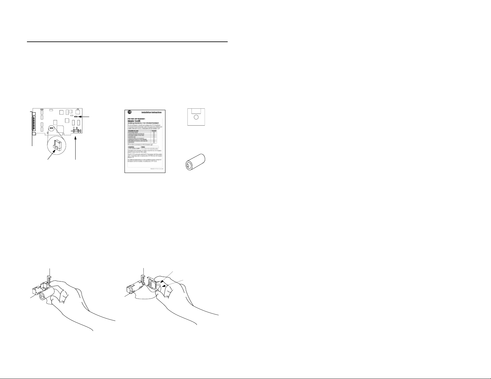
Verify Package Contents
Make sure that you have these items before you discard any packing
material. If an item is missing or incorrect, contact your local sales
representative.
PCI Bus card Installation instructions
(Publication 1747-5.31)
Jumper
for
Battery
Back-up
3.5” Software
Utility disk
PCI Bus card battery
Base Memory
Address Jumper
Battery
30578-M
Installing the Battery and its Connecting Jumper
A battery has been incl uded for your scanner . You must install the battery
and jumper on the sc anner before you i nstall the sca nner in the compute r.
Install the battery as shown below.
1. Plug the battery in as shown below 2. Plug the jumper in as shown below.
IMPORTANT: When you install the
jumper, the red wire must be on top
and the white wire in the middle.
Red wire
White wire
41176-M
30631-M
Publication 1747-5.31–April 1998
Page 4
4 PCI Bus Card for 1746 Local I/O
User SRAM
256K (1747-PCIS) or 1M (1747-PCIS2) batte ry backed-up SRAM exists
on the scanner to be used by the host CPU. The host applic ation defi nes
the SRAM’s function.
For additional information on access and use of the user SRAM when
using the API software, see 1747 PCI Bus Interface for 1746 Local I/O
API Software user manual, publication 1747-6.5.3. If you are using
another software application, refer to the documentation for that software.
Setting the Jumper for Battery Back-Up
The PCI Bus card uses an o n board jumper that can be set in either of two
positions:
Enabled - This sett ing pr ovides batte ry bac k-up f or bot h Dual P ort
•
RAM and User SRAM. This mode wi ll substantially decrease t he
battery life.
or
Disabled - This setting provides battery back-up for SRAM only
•
The default position on the jumper is to the disabled pos ition. The jumper
for battery back-up looks like this:.
Jumper for
battery back-up
Publication 1747-5.31–April 1998
Enabled position
Disabled position
41177-M
Page 5
PCI Bus Card for 1746 Local I/O 5
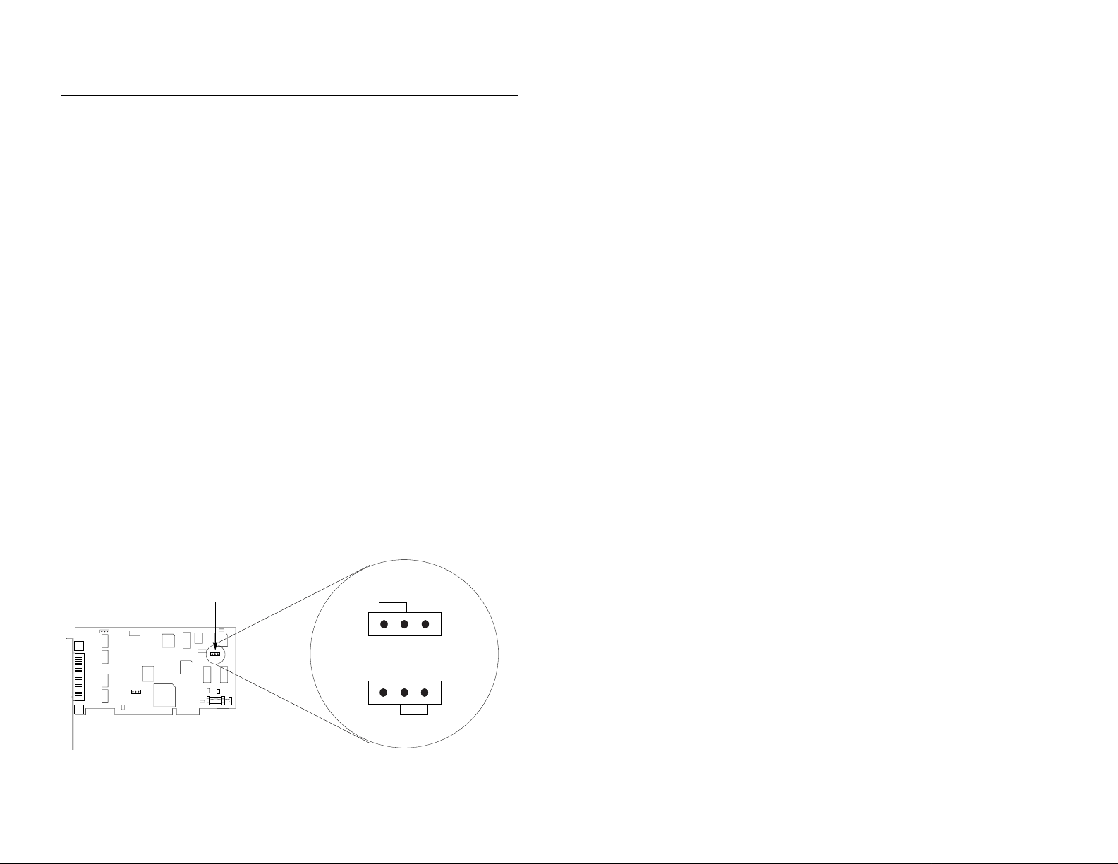
Setting the Base Memory Address Jumper
The host computer and the PCI Bus card exchange data via a dual-port
interface. The dual-por t requires 4 Kbytes of memory . This 4 Kbyte block
of memory begins at the base memor y address assigned to the card by the
PCI BIOS when the computer is started.
Under MS-DOS, Windows 3.1 and Windows for Workgroups, the base
memory address of PC cards should fall within the range of 0 and 1
Megabyte of PC memory. For the newer 32-bit operating systems, this
restriction is n o longer requ ired, and the ba se memory addr ess shoul d be
located anywhere in the PC memory space.
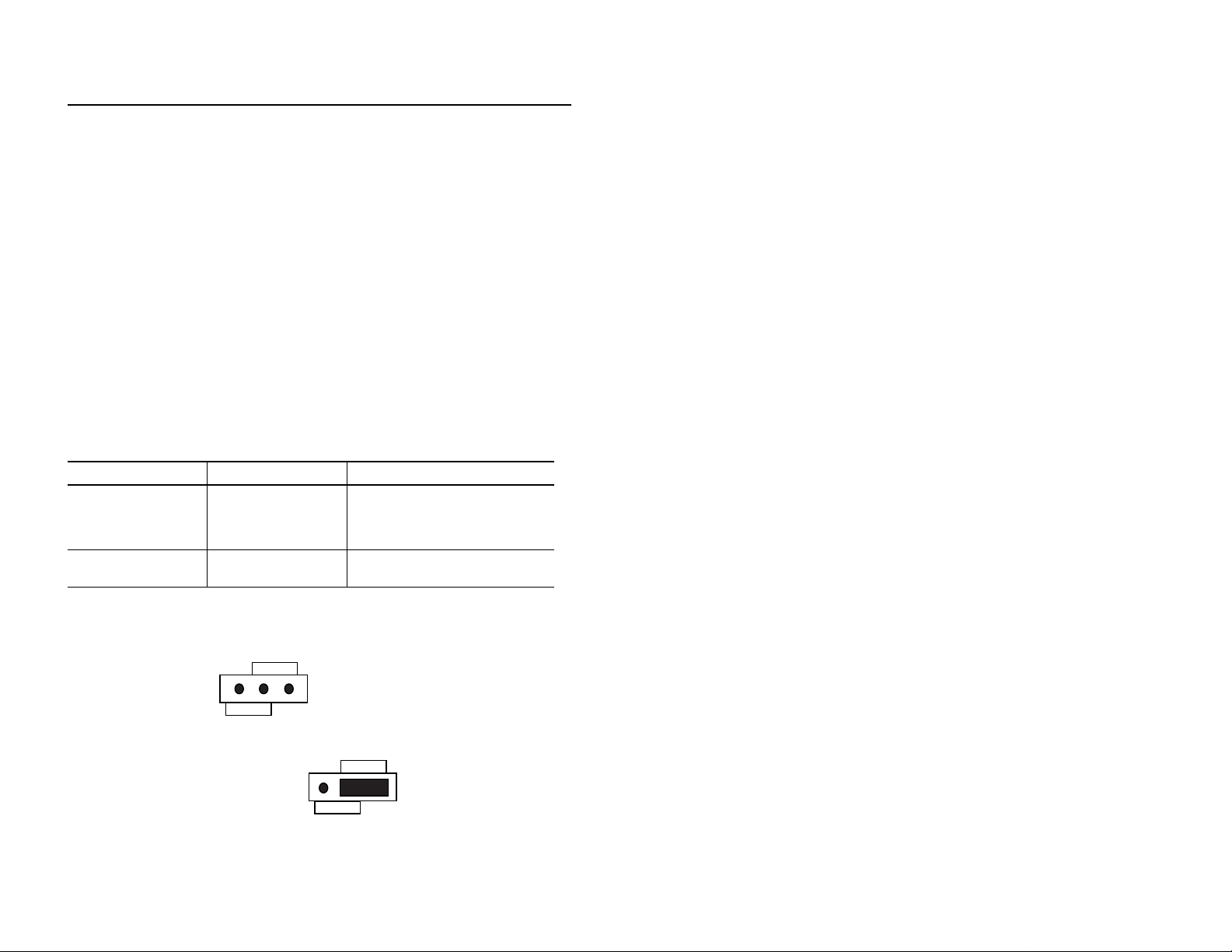
The Base Memory Address j umper (J P2) f orces the PCI BIOS to assign
the base memory address to one of two address ranges, as shown in the
table below . Y ou should s elect the jumper position ba sed on the operating
system running on your PC.
Operating System Jumper Position (JP2) Base Memory Address Range
DOS
Windows 3.1
Windows for Workgroups
Non-Microsoft system
Windows 95
Windows NT
Toward 1Meg position Located in the range between 0 and
1Mb in the PC memory
Toward 32bit position Located anywhere in the available
physical memory of the PC
When looking directly at the 1747-PCIS card, the Base Memory Address
jumper looks like this:
32BIT
This is a jumper that is not covered.
1MEG
32BIT
This is a jumper that has the 32bit
position for Windows 95 covered.
1MEG
Publication 1747-5.31–April 1998
Page 6

6 PCI Bus Card for 1746 Local I/O
Accessing the Computer’s PCI Bus Slots
To install the s ca nner, you must h ave access to the comput er’s PCI bus.
Refer to your comput er’s h ardware manual for inst ructions ab out how to:
1. Shut down the computer’s operating system.
2. Turn off power to the computer.
Important: If y ou disconnect t he ac power fr om the computer , you lose
the chassis ground. El ectrost atic damag e (ESD) protect ion
is lost.
3. Remove the computer’s CP U cover (acc ording to t he manu factu rer’ s
instructions).
4. Select a vacant PCI bus slot.
Important: The scanner will only function in a PCI bus slot.
5. Remove the rear bracket slot’ s expansion cover by loosening the screw
on the back of the computer.
Publication 1747-5.31–April 1998
Page 7

PCI Bus Card for 1746 Local I/O 7
Installing the Scanner
To install the scanner inside the computer:
1. Turn off power to the computer.
Important: If y ou disconnect t he ac power fr om the computer , you lose
the chassis ground. Electros tat ic damage (ESD) protection
is lost.
2. Loosen the expansion slot screw and remove the outside retaining
bracket.
3. Insert the scanner into the edge connector and tighten the expansion
slot screw on the scanner outside retaining bracket.
4. Restore power to the computer.
5. Run PCI diagnostics from the Utility disk to obtain the memory and
interrupt assigned to the scanner by BIOS at power up. Place the
software disk in the PC.
6. Type:
a:\PCISID.EXE.
7. Hit <E nter>.
Selecting the Cable for Your Connections
The scanner must be connec ted to the adapt er. Use one of t he foll owing
cables to make the connection:
3m interconnect cable (Cat. No. 1747-PCIC)
•
10m interconnect cable (Cat. No. 1747-PCIC2)
•
Publication 1747-5.31–April 1998
Page 8
8 PCI Bus Card for 1746 Local I/O
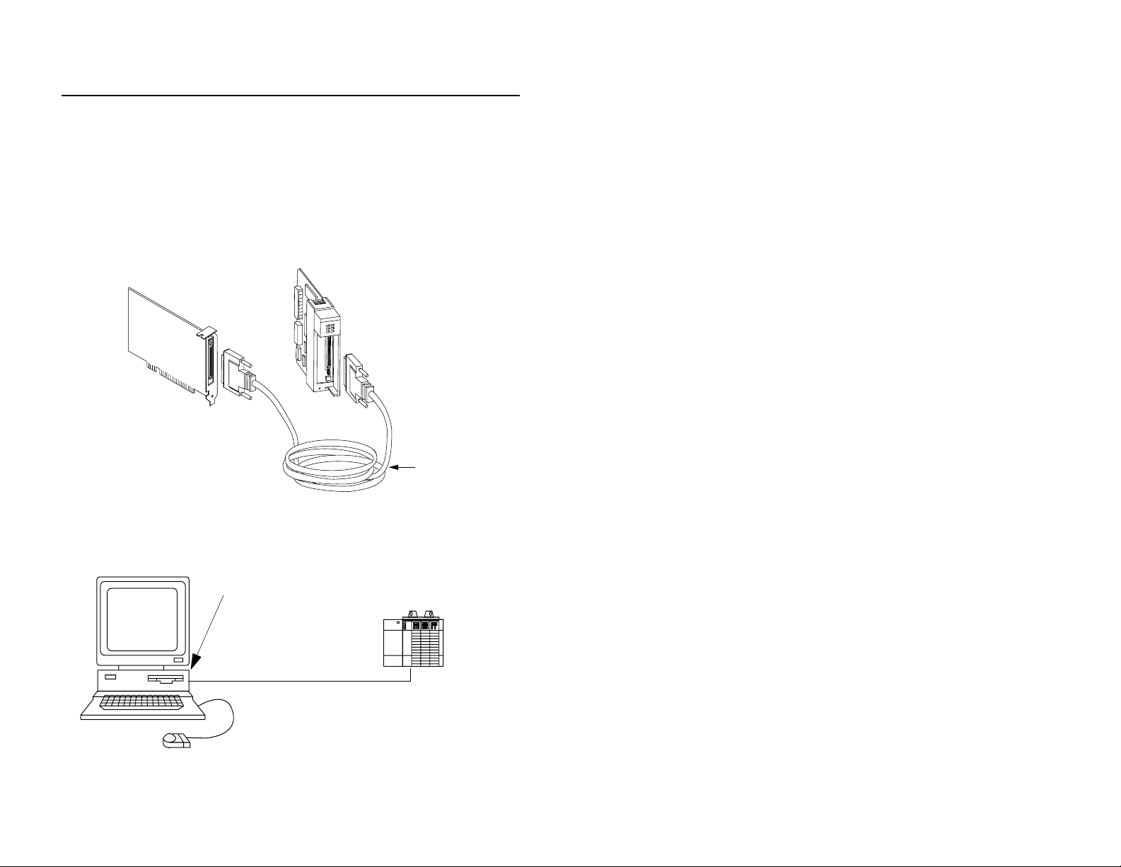
Connecting the Scanner to the Adapter
To connect the scanner to the adapter, you must:
1. Connect one end of the 1747-PCIC cable to the scanner.
2. Connect the other end of the 1747-PCIC cable to the ad apt er. Either
end of cable can connect to either the scanner or adapter.
PCI Bus card
(scanner)
Chassis Interface module
(Adapter)
1747-PCIC cable
30576-M
The figure below shows an example of a c onne ct ion be twee n a PCI Bus
card inside the computer and a Chassis Interface module inside a
local chassis.
PCI Bus card (inside
the computer)
Personal Computer
Publication 1747-5.31–April 1998
1747-PCIC Cable
Chassis Interface
module (insid e t h e
local chassis)
30173
Page 9

PCI Bus Card for 1746 Local I/O 9
General Operation
The scanner is a PCI Bus ca rd that i s instal led in a PC. I t scans 17 46 I/O
modules via the 1747-PCIC cable and adapter. The scanner can
communicate to any 1746 I/O module.
The application program on the PC will provide the software driver to
initialize and control the scanner. Once the scanner is running, it
continuously retrieves all the input data from the 1746 I/O modul es and
places the data in dual po rt memory on board the scanner. Output data is
constantly sent fr om the same dual port memory to the 1746 I/O mod ules.
Calculating Scan Time
Scan time represents the elapsed time it takes your scanner to retrieve
input data from all I/O modules and place it in dua l por t memor y on the
scanner one time.
Add the rows in the following tables to calculate input and output scan
times. Fill in the shaded boxes. All times are in microseconds.
Estimate Minimum Input Scan Time
Quantity Fixed Scan
Digital I/O Modules:
number of class 0 input words:
Specialty I/O Modules (Class 1)
number of 1746-BAS modules (class 1):
number of 1746-NIO4V modules:
number of 1746-FIO4V modules:
number of 1746-NI4V modules:
Specialty I/O Modules (Class 3 and 4)
number of 1746-HSCE modules:
number of 1747-SN modules:
number of 1746-BAS modules (class 4):
Forced Input Overhead
number of class 0 input words:
number of specialty input words:
number of specialty I/O modules:
Input Scan Overhead (Add this time to the total from the I/O modules) 36
Minimum Input Scan Time (total)
Time
X 48 =
X 490 =
X 265 =
X 265 =
X 325 =
X 712 =
X 1185 =
X 650 =
X 6 =
X 9=
X 30 =
Total
Publication 1747-5.31–April 1998
Page 10

10 PCI Bus Card for 1746 Local I/O
Estimate Maximum Input Scan Time
Minimum Input Scan Time
(from previous table)
Maximum Specialty I/O Input Scan Time
number of class 1 specialty I/O modules:
number of class 3 and 4 specialty I/O modules:
Quantity Fixed Scan
Time
X 50 =
X 200 =
Maximum Input Scan Time (total)
Total
Estimate Minimum Output Scan Time
Quantity Fixed Scan
Digital I/O Modules:
number of class 0 input words:
Specialty I/O Modules (Class 1)
number of 1746-BAS modules (class 1):
number of 1746-NIO4V modules:
number of 1746-FIO4V modules:
number of 1746-NO4V modules:
Specialty I/O Modules (Class 3 and 4)
number of 1746-HSCE modules:
number of 1747-SN modules:
number of 1746-BAS modules (class 4):
Forced Output Overhead
number of class 0 output words:
number of specialty output words:
number of specialty I/O modules:
Output Scan Overhead (Add this time to the total from the I/O modules) 36
Minimum Input Scan Time (total)
Time
X 46 =
X 500 =
X 277 =
X 277 =
X 330 =
X 608 =
X 1208 =
X 655 =
X 6 =
X 9=
X 30 =
Total
Publication 1747-5.31–April 1998
Page 11

PCI Bus Card for 1746 Local I/O 11
Estimate Maximum Output Scan Time
Minimum Input Scan Time
(from above table)
Maximum Specialty I/O Output Scan Time
number of class 1 specialty I/O modules:
number of class 3 and 4 specialty I/O modules:
Quantity Fixed Scan
Time
X 50 =
X 200 =
Maximum Output Scan Time (total)
Total
Estimate Output Scan Time Plus Processor Overhead
Minimum or Maximum Output Scan Time
(from previous tables)
Overhead if DII Enabled 60
Processor Overhead minimum = 140
Output Scan Time Plus Processor Overhead (total)
maximum = 200
Troubleshooting
Use the utilit es disk that came in this packa ge for troubleshooting.
The diagnostic/util ity disk ha s a readme.tx t file that e xplains t he utilit ies
on the disk and directions on how to execute them.
We recommend that you make the diagnostic/utility disk bootable (use
the DOS
SYS command) so you can run diagnos tic utilit ies dire ctly fro m
a floppy drive in the PC. The PCI bus card must have the base memory
address jumper set for DOS (1 Meg position).
The diagnostic utility disk contains these utilities:
This utility selection: Uses this executable:
scanner diagnostics ocdiag.exe
PCI backplane/card utility pcisid.exe
Publication 1747-5.31–April 1998
Page 12

12 PCI Bus Card for 1746 Local I/O
•
Specifications
Operational Slot Temperature 0 to 60
Non-operational Slot Temperature -40 to 85
Relative Humidity 5-95% without condensation
Vibration
10-60Hz
60-150Hz
Operational Shock 30G peak for 11 +/-1ms
Non-operational Shock 50G peak for 11 +/-1ms
Power Dissipation 600mA @ 5V dc
Agency Certification
(when product or packaging is marked)
o
o
Constant 0.012 in displacement
Constant 2.0G acceleration
3W
U
listed
R
USC
L
marked for all applicable directives
Worldwide representation.
Argentina • Australia • Austria • Bahrain • Belgium • Brazil • Bulgaria • Canada • Chile • China, PRC •
Colombia • Costa Rica • Croatia • Cyprus • Czech Republic • Denmark • Ecuador • Egypt • El Salvador • Finland •
France • Germany • Greece • Guatemala • Honduras • Hong Kong • Hungary • Iceland • India • Indonesia •
Ireland • Israel • Italy • Jamaica • Japan • Jordan • Korea • Kuwait • Lebanon • Malaysia • Mexico • Netherlands
New Zealand • Norway • Pakistan • Peru • Philippines • Poland • Portugal • Puerto Rico • Qatar • Romania •
Russia-CIS • Saudi Arabia • Singapore • Slovakia • Slovenia • South Africa, Republic • Spain • Sweden •
Switzerland • Tai wan • Thailand • Turke y • United Arab Emirates • United Kingdom • United States • Uruguay •
Venezuela • Yugoslavia
Allen-Bradley Headquarters, 1201 South Second Street, Milwaukee, WI 53204 USA,
Tel: (1) 414 382-2000 Fax: (1) 414 382-4444
Publication 1747-5.31-April 1998 PN 955131-20
Copyright 1997 Allen-Bradley, Inc. Printed in USA
 Loading...