

Page 1
Installation Instructions
POINT I/O Module with 8 Configurable
24V DC Points and DeviceLogix
Catalog Numbers 1734-8CFGDLX
Topic Page
Important User Information 2
Environment and Enclosure 3
Prevent Electrostatic Discharge 4
About the Module 4
Before You Begin 5
Install the Mounting Base 6
Install the Module 7
Install the Removable Terminal Block 9
Wire the Module 11
Wiring Diagram 12
Configure the Module 13
Interpret the Indicators 20
Specifications 23
Page 2
2 POINT I/O Module with 8 Configurable 24V DC Points and DeviceLogix
Important User Information
Solid state equipment has operational characteristics differing from those of electromechanical
equipment. Safety Guidelines for the Application, Installation and Maintenance of Solid State Controls
(Publication SGI-1.1 available from your local Rockwell Automation sales office or online at
http://literature.rockwellautomation.com) describes some important differences between solid state
equipment and hard-wired electromechanical devices. Because of this difference, and also because of
the wide variety of uses for solid state equipment, all persons responsible for applying this equipment
must satisfy themselves that each intended application of this equipment is acceptable.
In no event will Rockwell Automation, Inc. be responsible or liable for indirect or consequential damages
resulting from the use or application of this equipment.
The examples and diagrams in this manual are included solely for illustrative purposes. Because of the
many variables and requirements associated with any particular installation, Rockwell Automation, Inc.
cannot assume responsibility or liability for actual use based on the examples and diagrams.
No patent liability is assumed by Rockwell Automation, Inc. with respect to use of information, circuits,
equipment, or software described in this manual.
Reproduction of the contents of this manual, in whole or in part, without written permission of Rockwell
Automation, Inc., is prohibited.
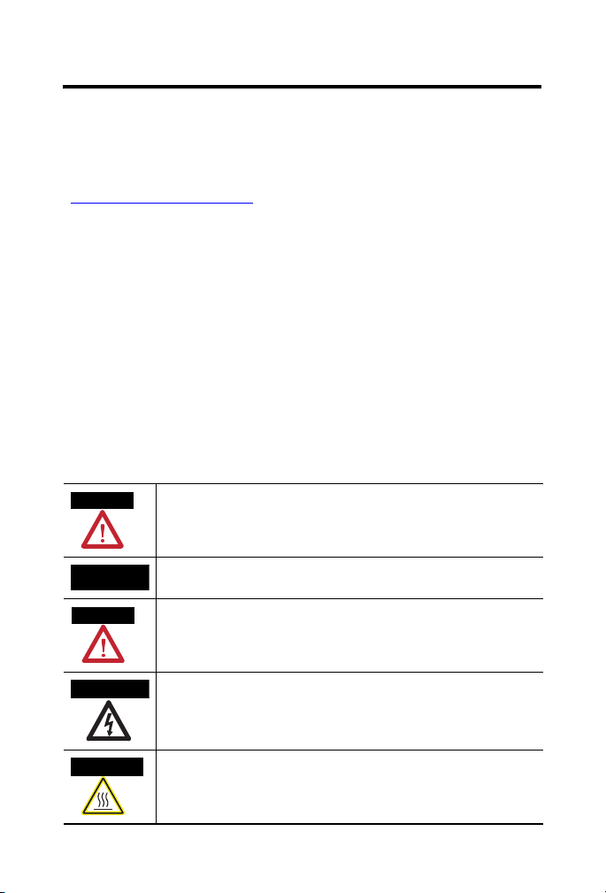
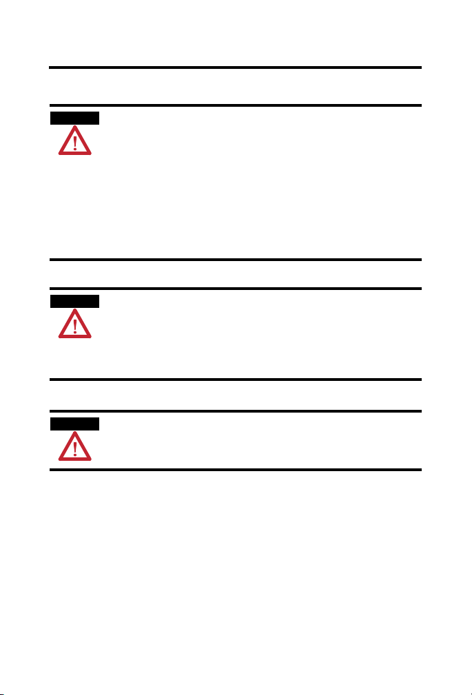
Throughout this manual, when necessary, we use notes to make you aware of safety considerations.
WARNING
Identifies information about practices or circumstances that can cause an explosion
in a hazardous environment, which may lead to personal injury or death, property
damage, or economic loss.
IMPORTANT
ATTENTION
SHOCK HAZARD
BURN HAZARD
Publication
Identifies information that is critical for successful application and understanding of
the product.
Identifies information about practices or circumstances that can lead to personal
injury or death, property damage, or economic loss. Attentions help you identify a
hazard, avoid a hazard and recognize the consequences.
Labels may be on or inside the equipment (for example, drive or motor) to alert
people that dangerous voltage may be present.
Labels may be on or inside the equipment (for example, drive or motor) to alert
people that surfaces may reach dangerous temperatures.
1734-IN039A-EN-P - March 2009
Page 3

POINT I/O Module with 8 Configurable 24V DC Points and DeviceLogix 3
Environment and Enclosure
ATTENTION
This equipment is intended for use in a Pollution Degree 2 industrial
environment, in overvoltage Category II applications (as defined in
IEC
60664-1), at altitudes up to 2000 m (6562 ft) without derating.
This equipment is considered Group 1, Class A industrial equipment according
to IEC/CISPR
with electromagnetic compatibility in residential and other environments due
to conducted and radiated disturbances.
This equipment is supplied as open-type equipment. It must be mounted within
an enclosure that is suitably designed for those specific environmental
conditions that will be present and appropriately designed to prevent personal
injury resulting from accessibility to live parts. The enclosure must have
suitable flame-retardant properties to prevent or minimize the spread of flame,
complying with a flame spread rating of 5VA, V2, V1, V0 (or equivalent) if
non-metallic. The interior of the enclosure must be accessible only by the use
of a tool. Subsequent sections of this publication may contain additional
information regarding specific enclosure type ratings that are required to
comply with certain product safety certifications.
In addition to this publication, see:
• Industrial Automation Wiring and Grounding Guidelines, Allen-Bradley
• NEMA Standards 250 and IEC 60529, as applicable, for explanations of
11. Without appropriate precautions, there may be difficulties
publication 1770-4.1
the degrees of protection provided by different types of enclosure.
, for additional installation requirements.
Publication
1734-IN039A-EN-P - March 2009
Page 4
4 POINT I/O Module with 8 Configurable 24V DC Points and DeviceLogix
Prevent Electrostatic Discharge
ATTENTION
ATTENTION
ATTENTION
This equipment is sensitive to electrostatic discharge, which can cause
internal damage and affect normal operation. Follow these guidelines when
you handle this equipment.
• Touch a grounded object to discharge potential static.
• Wear an approved grounding wriststrap.
• Do not touch connectors or pins on component boards.
• Do not touch circuit components inside the equipment.
• Use a static-safe workstation, if available.
• Store the equipment in appropriate static-safe packaging when not in
use.
POINT I/O is grounded through the DIN rail to chassis ground. Use zinc plated
yellow-chromate steel DIN rail to assure proper grounding. The use of other
DIN rail materials (for example, aluminum or plastic) that can corrode, oxidize,
or are poor conductors, can result in improper or intermittent grounding.
Secure DIN rail to mounting surface approximately every 200 mm (7.87 in.) and
use end-anchors appropriately.
To comply with the CE Low Voltage Directive (LVD), all connected I/O must be
powered from a source compliant with the following:
Safety Extra Low Voltage (SELV) or Protected Extra Low Voltage (PELV).
About the Module
The 1734-8CFGDLX module is an 8-point 24V DC I/O module with 8
self-configuring points and DeviceLogix capabilities. Each of the I/O points
can be a DC input or output.
The module supports removal and insertion under power, auto-address, and
auto-baud in compliance with the POINTBus backplane.
Publication
1734-IN039A-EN-P - March 2009
Page 5
POINT I/O Module with 8 Configurable 24V DC Points and DeviceLogix 5
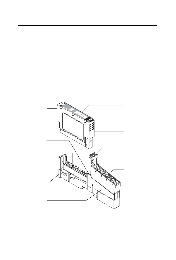
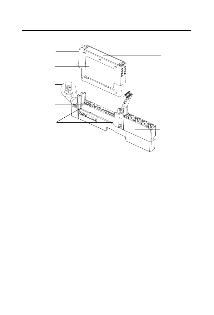
Before You Begin
See the figures to familiarize yourself with major parts of the module, noting
that the wiring base assembly is one of the following:
• 1734-TB or 1734-TBS POINT I/O two-piece terminal base, which
includes the 1734-RTB removable terminal block and 1734-MB
mounting base
• 1734-TOP or 1734-TOPS POINT I/O one-piece terminal base
The 1734-8CFGDLX module is not compatible with 1734-TB3, 1734-TB3S,
1734-TOP3, and 1734-TOP3S terminal bases.
Module Locking
Mechanism
Module Wiring
Diagram
DIN Rail Locking
Screw (orange)
Mechanical
Keying (orange)
Interlocking Side
Pieces
Mounting Base
Module
Status
Network
Status
NODE:
4
5
0
6
1
7
2
3
Slide-in Writable
Label
Insertable I/O
Module
RTB Removal
Handle
Removable Terminal
Block (RTB)
44713
Publication
1734-IN039A-EN-P - March 2009
Page 6
6 POINT I/O Module with 8 Configurable 24V DC Points and DeviceLogix
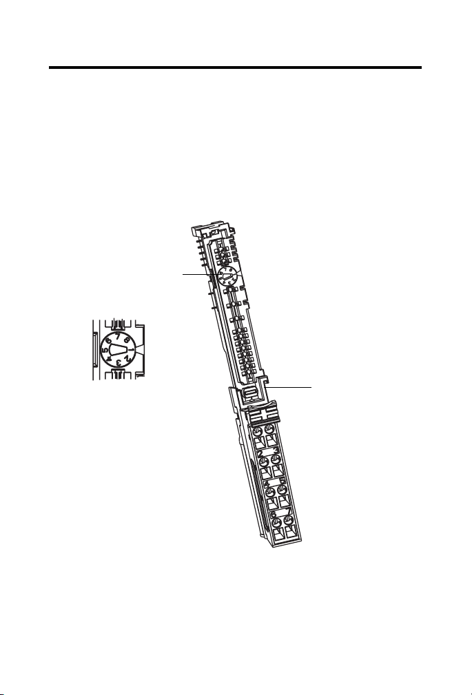
Module Locking
Mechanism
Module Wiring
Diagram
DIN Rail Locking
Screw (orange)
Mechanical
Keying (orange)
Interlocking
Side Pieces
44714
Install the Mounting Base
Follow these steps to install the mounting base on the DIN rail.
1. Position the mounting base vertically above the installed units, for
example, adapter, power supply, or existing module.
2. Slide the mounting base down so that the interlocking side pieces
engage the adjacent module or adapter.
Slide-in
Writable Label
Insertable
I/O Module
Handle
1734-TOP or
1734-TOPS
One-piece
Terminal Base
with Screw or
Spring Clamp
3. Press firmly to seat the mounting base on the DIN rail until the
mounting base snaps into place.
4. To remove the mounting base from the DIN rail, remove the module,
and use a small bladed screwdriver to rotate the base locking screw to
a vertical position. This releases the locking mechanism. Then lift
straight up to remove.
Publication
1734-IN039A-EN-P - March 2009
Page 7
POINT I/O Module with 8 Configurable 24V DC Points and DeviceLogix 7
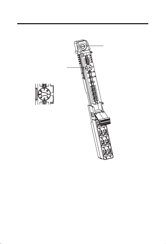
Install the Module
The module can be installed before, or after base installation. Make sure the
mounting base is correctly keyed before installing the module into the
mounting base. In addition, make sure the mounting base locking screw is
positioned horizontal referenced to the base.
1734-TB Base
Turn the keyswitch to align
the number with the notch.
Notch position 1 is shown.
44710
Publication
Be sure the DIN-rail
locking screw is in the
horizontal position.
44715
1734-IN039A-EN-P - March 2009
Page 8
8 POINT I/O Module with 8 Configurable 24V DC Points and DeviceLogix
1734-TOP Base
Be sure the DIN-rail
locking screw is in the
horizontal position.
Turn the keyswitch to align
the number with the notch.
Notch position 1 is shown.
44710
44228
Follow these steps to install the module.
1. Use a bladed screwdriver to rotate the keyswitch on the mounting
base clockwise until the number required for the type of module being
installed aligns with the notch in the base.
2. Make certain the DIN-rail locking screw is in the horizontal position.
(You cannot insert the module if the locking mechanism is unlocked.)
3. Insert the module straight down into the mounting base and press to
secure. The module will lock into place.
Publication
1734-IN039A-EN-P - March 2009
Page 9

POINT I/O Module with 8 Configurable 24V DC Points and DeviceLogix 9
Install the Removable Terminal Block
Read this for information if a removable terminal block (RTB) is supplied
with your wiring base assembly, noting that 1734-TOP and 1734-TOPS bases
do not have an RTB.
To insert the RTB, proceed as follows. Note that if you pull up on the RTB
handle to remove the RTB, you can remove and replace the mounting base as
necessary without removing any of the wiring.
1. Insert the end opposite the handle into the base unit, noting that this
end has a curved section that engages with the wiring base.
2. Rotate the terminal block into the wiring base until it locks itself into
place.
3. If an I/O module is installed, snap the RTB handle into place on the
module.
Remove a Mounting Base
To remove a mounting base, you must first remove any installed module and
the module installed in the base to the right.
1. For a module with a two-piece terminal base, use these steps;
otherwise, use step 2
a. Remove the removable terminal block (RTB), if wired.
b. Unlatch the RTB handle on the I/O module.
c. Pull on the RTB handle to remove the RTB.
.
2. Press on the module lock on the top of the module.
3. Pull on the I/O module to remove from the base.
4. Repeat steps 1, 2, 3, and 4 for the module to the right.
5. Lift straight up to remove.
Publication
1734-IN039A-EN-P - March 2009
Page 10

10 POINT I/O Module with 8 Configurable 24V DC Points and DeviceLogix
Install a 1734-TOPS Base
1. Position the base vertically above the installed units, such as an
adapter, power supply, or existing module.
2. Slide the base down, allowing the interlocking side pieces to engage
the adjacent installed unit.
3. Press firmly to seat the base on the DIN rail until the base snaps into
place.
4. Verify that the DIN-rail locking screw is in a horizontal, locked
position before inserting an I/O module.
Remove a 1734-TOPS Base
To remove a wiring base from the DIN rail, you must remove the module
installed to the right of the base.
1. Squeeze the module locking mechanism of the module to the right of
the base, pulling up to remove the module.
2. Turn the orange locking screw to a vertical position to unlock the base
from the DIN rail.
3. Slide the base up to release it from its mating units.
Publication
1734-IN039A-EN-P - March 2009
Page 11

POINT I/O Module with 8 Configurable 24V DC Points and DeviceLogix 11
Wire the Module
See the figure and tables for information about how to wire the module.
1734-8CFGDLX
I/O 0
Module
Status
Network
Status
NODE:
Device
Logix
Status
0
0
1
1
2
2
3
3
1734
8CFGDLX
Status of I/O 4
4
5
Status of I/O 5
Status of I/O 6
6
Status of I/O 7
7
7
I/O 1
Module Status
Network Status
DeviceLogix Status
Status of I/O 0
Status of I/O 1
Status of I/O 2
Status of I/O 3
I/O 2 I/O 3
I/O 4 I/O 5
I/O 6 I/O 7
44758
Note that voltage and current to the module is applied through the adapter,
the 1734-FPD module, or the 1734-EP24DC module. V = 10…28.8 V DC.
Publication
1734-IN039A-EN-P - March 2009
Page 12

12 POINT I/O Module with 8 Configurable 24V DC Points and DeviceLogix
Wiring Diagram
Prox
Prox
Prox
Prox
I/O 0
I/O 2
I/O 4
I/O 6
I/O 1
I/O 3
I/O 5
I/O 7
Load
Load
Load
Load
VC C
If a connection to Common or the Supply Voltage is required for two- or three- wire
devices, then a 1734-CTM or 1734-VTM can be used.
Each I/O point is Input or Output.
Channel Terminal Number
I/O Common Voltage
00
External
(1)
External
11
22
33
44
55
66
77
10/28.8 V DC is supplied through the internal power bus.
(1)
Common connections require an external connection, such as a 1734-CTM module.
(2)
Supply Voltage Connections require an external connection such as a 1734-VTM module.
Publication
1734-IN039A-EN-P - March 2009
44687
(2)
Page 13

POINT I/O Module with 8 Configurable 24V DC Points and DeviceLogix 13
Configure the Module
Read this section for information about how to communicate with your
module.
I/O messages are sent to (consumed) and received from (produced) the
POINT I/O modules. These messages are mapped into the processor’s or
scanner’s memory. Each module produces 1, 8 or 20 bytes of input data based
on which produced assembly is selected. The default setup is 20 bytes.
It consumes 1, 8 or 20 bytes of I/O data (scanner Tx).
Default Data Map - Produced Assembly Instance 101
Message Size: 20 Bytes
Bit 7 6 5 4 3 2 1 0
Data [0] Pt 07 Pt 06 Pt 05 Pt 04 Pt 03 Pt 02 Pt 01 Pt 00
Data [1] PNB 07 PNB 06 PNB 05 PNB 04 PNB 03 PNB 02 PNB 01 PNB 00
Data [2] Reserved Owned
Data [3] PM7 PM6 PM5 PM4 PM3 PM2 PM1 PM0
Data [4] Produce Network Analog Word 0
Data [5]
Data [6] Produce Network Analog Word 1
Data [7]
Data [8] Produce Network Analog Word 2
Data [9]
Data [10] Produce Network Analog Word 3
Data [11]
Data [12] Produce Network Analog Word 4
Data [13]
Data [14] Produce Network Analog Word 5
Data [15]
LogicEn
Publication
1734-IN039A-EN-P - March 2009
Page 14

14 POINT I/O Module with 8 Configurable 24V DC Points and DeviceLogix
Default Data Map - Produced Assembly Instance 101 (Continued)
Message Size: 20 Bytes
Data [16] Produce Network Analog Word 6
Data [17]
Data [18] Produce Network Analog Word 7
Data [19]
Where:
• Pt = state of the output point,
• PNB = Produce Network Bit,
• PM = Peer Missing (each bit represents the presence of a configured peer)
• Owned = Owned by a master.
When set to 0, the module is producing data without a master.
When set to 1, the module is producing while being owned by a master.
• LogicEn = Logic Enabled (0 = logic disabled, 1 = logic enabled)
You can select other produced assemblies:
• Produced assembly instance 4 is the first byte of produced assembly
instance 101 (Data [0]).
• Produced assembly instance 111 is the first eight bytes of produced
assembly instance 101 (Data [0]…[7]).
In RSLogix5000, the default tags will be:
• AdapterName:SlotNumber:I.Data
• AdapterName:SlotNumber:I.LogicDefinedData
• AdapterName:SlotNumber:I.Status.LogicEnabled
• AdapterName:SlotNumber:I.Status.Owned
• AdapterName:SlotNumber:I.PeerMissing
• AdapterName:SlotNumber:I.LogicDefinedIntData[0...7]
Publication
1734-IN039A-EN-P - March 2009
Page 15

POINT I/O Module with 8 Configurable 24V DC Points and DeviceLogix 15
Default Data Map - Consumed Assembly Instance 102
Message Size: 20 Bytes
Bit 7 6 5 4 3 2 1 0
Data [0] Pt 07 Pt 06 Pt 05 Pt 04 Pt 03 Pt 02 Pt 01 Pt 00
Data [1]
Data [2] Reserved
Data [3]
Data [4] Consume Network Analog Word 0
Data [5]
Data [6] Consume Network Analog Word 1
Data [7]
Data [8] Consume Network Analog Word 2
Data [9]
Data [10] Consume Network Analog Word 3
Data [11]
Data [12] Consume Network Analog Word 4
Data [13]
Data [14] Consume Network Analog Word 5
Data [15]
Data [16] Consume Network Analog Word 6
Data [17]
Data [18] Consume Network Analog Word 7
Data [19]
Where: Pt = state of the output point, CNB = Consume Network Bit
CNB 07 CNB 06 CNB 05 CNB 04 CNB 03 CNB 02 CNB 01 CNB 00
Publication
1734-IN039A-EN-P - March 2009
Page 16

16 POINT I/O Module with 8 Configurable 24V DC Points and DeviceLogix
You can select other consumed assemblies:
• Consumed assembly instance 34 is the first byte of consumed
assembly instance 102 (Data [0]).
• Consumed assembly instance 112 is the first eight bytes of consumed
assembly instance 102 (Data [0]…[7]).
In RSLogix5000, the default tags will be:
• AdapterName:SlotNumber:O.Data
• AdapterName:SlotNumber:O.LogicDefinedData
• AdapterName:SlotNumber:O.LogicDefinedIntData[0...7]
Data Map - Configuration Assembly Instance 123
Message Size: 48 Bytes
Bit
Data [0] Group Off2On Input filter
Data [1]
Data [2] Group On2Off Input filter
Data [3]
Data [4] FltM 7 FltM 6 FltM 5 FltM 4 FltM 3 FltM 2 FltM 1 FltM 0
Data [5] FltV 7 FltV 6 FltV 5 FltV 4 FltV 3 FltV 2 FltV 1 FltV 0
Data [6] IdlM 7 IdlM 6 IdlM 5 IdlM 4 IdlM 3 IdlM 2 IdlM 1 IdlM 0
Data [7] IdlV 7 IdlV 6 IdlV 5 IdlV 4 IdlV 3 IdlV 2 IdlV 1 IdlV 0
Data [8]
Data [9] Reserved
Data [10] Masterless Produce Assembly Instance (0, 4, 101, 111)
Data [11]
Data [12] Masterless Produce EPR (ms)
Data [13]
7 6 5 4 3 2 1 0
Reserved
RACK CFO DM MP
Publication
1734-IN039A-EN-P - March 2009
Page 17

POINT I/O Module with 8 Configurable 24V DC Points and DeviceLogix 17
Data Map - Configuration Assembly Instance 123 (Continued)
Message Size: 48 Bytes
Data [14] Masterless Produce PIT (ms)
Data [15]
Data [16] Peer 0 - Slot/MacID
Data [17] Peer 0 - Consume Message Length (bytes)
Data [18] Peer 0 - EPR (ms)
Data [19]
Data [20] Peer 1 - Slot/MacID
Data [21] Peer 1 - Consume Message Length (bytes)
Data [22] Peer 1 - EPR (ms)
Data [23]
Data [24] Peer 2 - Slot/MacID
Data [25] Peer 2 - Consume Message Length (bytes)
Data [26] Peer 2 - EPR (ms)
Data [27]
Data [28] Peer 3 = Slot/MacID
Data [29] Peer 3 - Consume Message Length (bytes)
Data [30] Peer 3 - EPR (ms)
Data [31]
Data [32] Peer 4 - Slot/MacID
Data [33] Peer 4 - Consume Message Length (bytes)
Data [34] Peer 4 - EPS (ms)
Data [35]
Data [36] Peer 5 - Slot/MacID
Data [37] Peer 5 - Consume Message Length (bytes)
Publication
1734-IN039A-EN-P - March 2009
Page 18

18 POINT I/O Module with 8 Configurable 24V DC Points and DeviceLogix
Data Map - Configuration Assembly Instance 123 (Continued)
Message Size: 48 Bytes
Data [38] Peer 5 - EPR (ms)
Data [39]
Data [40] Peer 6 - Slot/MacID
Data [41] Peer 6 - Consume Message Length (bytes)
Data [42] Peer 6 - EPR (ms)
Data [43]
Data [44] Peer 7 - Slot/MacID
Data [45] Peer 7 - Consume Message Length (bytes)
Data [46] Peer 7 - EPR (ms)
Data [47]
Where:
• Filter = 0 to 65535 μs (1000 = default)
• FltM = Fault Mode (0 = Fault Value (default), 1 = Hold Last State)
• FltV = Fault Value (0 = OFF (default), 1 = ON)
• IdlM = Idle Mode (0 = Idle Value (default), 1 = Hold Last State)
• IdlV = Idle Value (0 = OFF (default), 1 = ON)
• RACK = Produce with Rack Assembly 4 and Consume Rack Assembly 34
(0 = Disabled (default), 1 = Enabled)
• CFO = DeviceLogix Communication Fault Override of Outputs
1 = Enabled. When enabled, the DeviceLogix program will continue to control the
outputs even in the event of a communication fault.
0 = Disabled (default). When disabled, the outputs will follow the Fault and Idle
settings.
• DM = Dependent Mode
• MP = Masterless Produce
0 = Disabled (default), 1 = Enabled. When enabled, the module will begin producing
data at powerup and after a connection with a controller is terminated.
Publication
1734-IN039A-EN-P - March 2009
Page 19

POINT I/O Module with 8 Configurable 24V DC Points and DeviceLogix 19
Data Map - Configuration Assembly Instance 123 (Continued)
Message Size: 48 Bytes
• EPR = Expected Packet Rate
• PIT = Production Inhibit Time
• Slot/MacID = Address of peer
Configuration of the 1734-8CFGDLX module must be done through
RSNetWorx for DeviceNet.
Publication
1734-IN039A-EN-P - March 2009
Page 20

20 POINT I/O Module with 8 Configurable 24V DC Points and DeviceLogix
Interpret the Indicators
See the figure and table that show how to interpret indicators.
Module Status
Network Status
DeviceLogix Status
Status of I/O 0
Status of I/O 1
Status of I/O 2
Status of I/O 3
Module
Status
Network
Status
NODE:
Device
Logix
Status
0
0
1
1
2
2
3
3
1734
8CFGDLX
Status of I/O 4
4
Status of I/O 5
5
Status of I/O 6
6
Status of I/O 7
7
44759
Module Status
Status Description Recommended action
Off No power applied to device. Apply power to device.
Green Device operating normally. None.
Flashing
green
Flashing red Recoverable fault. 1. Cycle power to device.
Red Unrecoverable fault may require
Flashing
red/green
Device needs commissioning due to
Configure device properly.
missing, incomplete or incorrect
configuration.
2. If condition persists, replace
device.
Replace device.
device replacement.
Device is in self-test. None.
Publication
1734-IN039A-EN-P - March 2009
Page 21

POINT I/O Module with 8 Configurable 24V DC Points and DeviceLogix 21
Network Status
Status Description Recommended action
Off Device is not online.
Green Device is online and has connections
Flashing
green
Flashing red One or more I/O connections in
Red Critical link failure - failed
Flashing
red/green
- Device has not completed
dup_MAC_id test.
- Device not powered - check module
status indicator.
in the established state.
Device is online but has no
connections in the established state.
timed-out state.
This could also mean a peer is not
producing data at all, or it is not
configured correctly.
communication device. Device
detected error that prevents it
communicating on the network.
Communication faulted device - the
device has detected a network
access error and is in communication
faulted state.
Device has received and accepted an
Identify Communication Faulted
Request - long protocol message.
Apply power to device, wait for
dup_MAC_id to complete, and
correct, as needed.
None.
None - device is in Idle or Program
mode.
Check I/O connection with master.
Verify peers are present and
configured properly.
Verify that adapter and terminal
bases are properly installed, and
reinstall, as needed.
Verify that adapter is properly
installed, and reinstall, as needed.
Publication
1734-IN039A-EN-P - March 2009
Page 22

22 POINT I/O Module with 8 Configurable 24V DC Points and DeviceLogix
DeviceLogix Status
Status Description Recommended action
Off DeviceLogix program is not
controlling outputs.
Green DeviceLogix program is controlling
outputs.
None.
None.
I/O Status
Status Description Recommended action
Off Input or output is in the OFF state. None.
Yel low Input or output is in the ON state. None.
Publication
1734-IN039A-EN-P - March 2009
Page 23

POINT I/O Module with 8 Configurable 24V DC Points and DeviceLogix 23
Specifications
Specifications for POINT I/O Module 1734-8CFGDLX DC Input
Attribute Value
On-state voltage, min 11V DC
On-state current, min 2.0 mA
On-state current, max 5.0 mA
Off-state voltage, max 5V DC
Off-state current, min 1.5 mA
Input filter Each input independently settable in 1 ms intervals
Off to On filter, min 0 μs
Off to On filter, max 65535 μs
On to Off filter, min 0 μs
On to Off filter, max 65535 μs
Specifications for POINT I/O Module 1734-8CFGDLX DC Output
Attribute Value
On-state voltage range, min 10V DC
On-state voltage range, max 28.8V DC
On-state voltage range, nom 24V DC
On-state voltage drop, max 0.4V DC
On-state current, max 0.5 A
Off-state leakage, max 0.5 mA
Module current (all outputs),
max
Surge current - for 100 ms,
repeatable every 2 s, max
(truncated to 1 ms resolution). Default value is 1000 μs.
3.0 A
1.0 A
Publication
1734-IN039A-EN-P - March 2009
Page 24

24 POINT I/O Module with 8 Configurable 24V DC Points and DeviceLogix
General Specifications
Attribute Value
Module location 1734-TB, 1734-TBS, 1734-TOP, and 1734-TOPS bases
POINTBus current, max 100 mA @ 5V DC
Power dissipation, max 2.6 W @ 28.8V DC
Thermal dissipation, max 8.9 BTU/hr @ 28.8V DC
Isolation voltage 50V (continuous), Reinforced Insulation Type
Type tested at 2121V DC for 60 s, field-side to system
No isolation between individual channels
Field power bus
Supply voltage, nom
Voltage range
Dimensions HxWxL, approx. 56 x 12 x 75.5 mm
Terminal block screw torque Determined by installed terminal block
Keyswitch position 1
Reverse polarity protection Yes
Enclosure type rating None (open-style)
Wire size Determined by installed terminal block.
Wire category
Pilot duty rating Not rated
(1)
Use this Conductor Category information for planning conductor routing. Refer to
Industrial Automation Wiring and Grounding Guidelines, publication 1770-4.1
24V DC
10…28.8V DC
2.2 x 0.47 x 2.97 in.
1 - on signal ports
(1)
.
Publication
1734-IN039A-EN-P - March 2009
Page 25

POINT I/O Module with 8 Configurable 24V DC Points and DeviceLogix 25
Environmental Specifications
Attribute Value
Temperature, operating IEC 60068-2-1 (Test Ad, Operating Cold),
IEC 60068-2-2 (Test Bd, Operating Dry Heat),
IEC 60068-2-14 (Test Nb, Operating Thermal Shock):
-20…55 °C (-4…131 °F)
Temperature,
non-operating
Relative humidity IEC 60068-2-30 (Test Db, Unpackaged Damp Heat):
Vibration IEC 60068-2-6 (Test Fc, Operating):
Shock, operating IEC 60068-2-27 (Test Ea, Unpackaged Shock)
Shock, non-operating IEC 60068-2-27 (Test Ea, Unpackaged Shock)
Emissions CISPR 11:
ESD immunity IEC 61000-4-2:
Radiated RF immunity IEC 61000-4-3:
IEC 60068-2-1 (Test Ab, Unpackaged Non-operating Cold),
IEC 60068-2-2 (Test Bb, Unpackaged Non-operating Dry Heat),
IEC 60068-2-14 (Test Na, Unpackaged Non-operating Thermal
Shock):
-40…85°C (-40…185°F)
5…95% noncondensing
5 g @ 10…500 Hz
30 g
50 g
Group 1, Class A
6 kV contact discharges
8 kV air discharges
10V/m with 1 kHz sine-wave 80% AM from 80…2000 MHz
10V/m with 200 Hz 50% Pulse 100% AM at 900 MHz
10V/m with 200 Hz 50% Pulse 100% AM at 1890 MHz
3V/m with 1 kHz sine-wave 80% AM from 2000…2700 MHz
Publication
1734-IN039A-EN-P - March 2009
Page 26

26 POINT I/O Module with 8 Configurable 24V DC Points and DeviceLogix
Environmental Specifications (Continued)
Attribute Value
EFT/B immunity IEC 61000-4-4:
±3 kV at 5 kHz on signal ports
Surge transient
immunity
Conducted RF immunity IEC 61000-4-6:
IEC 61000-4-5:
±1 kV line-line (DM) and ±2 kV line-earth (CM) on signal ports
10V rms with 1 kHz sine-wave 80% AM from 150 kHz…80 MHz
Publication
1734-IN039A-EN-P - March 2009
Page 27

POINT I/O Module with 8 Configurable 24V DC Points and DeviceLogix 27
Certifications
Certification (when
product is marked)
Value
(1)
CE European Union 2004/108/EC EMC Directive, compliant with:
EN 61326-1; Meas./Control/Lab., Industrial Requirements
EN 61000-6-2; Industrial Immunity
EN 61000-6-4; Industrial Emissions
EN 61131-2; Programmable Controllers (Clause 8, Zone A & B)
C-Tick Australian Radiocommunications Act, compliant with:
AS/NZS CISPR 11; Industrial Emissions
(1)
See the Product Certification link at http://www.ab.com for Declarations of Conformity, Certificates,
and other certification details.
Publication
1734-IN039A-EN-P - March 2009
Page 28

Rockwell Automation Support
Rockwell Automation provides technical information on the Web to assist you in using
its products. At http://support.rockwellautomation.com
, you can find technical
manuals, a knowledge base of FAQs, technical and application notes, sample code and
links to software service packs, and a MySupport feature that you can customize to
make the best use of these tools.
For an additional level of technical phone support for installation, configuration, and
troubleshooting, we offer TechConnect support programs. For more information,
contact your local distributor or Rockwell Automation representative, or visit
http://support.rockwellautomation.com
.
Installation Assistance
If you experience a problem within the first 24 hours of installation, please review the
information that's contained in this manual. You can also contact a special Customer
Support number for initial help in getting your product up and running.
United States 1.440.646.3434
Outside United States Please contact your local Rockwell Automation representative for any
Monday – Friday, 8 a.m. – 5 p.m. EST
technical support issues.
New Product Satisfaction Return
Rockwell Automation tests all of its products to ensure that they are fully operational
when shipped from the manufacturing facility. However, if your product is not
functioning and needs to be returned, follow these procedures.
United States Contact your distributor. You must provide a Customer Support case number
Outside United States Please contact your local Rockwell Automation representative for the return
Allen-Bradley, POINT I/O, POINTBus, Rockwell Automation, and TechConnect are trademarks of Rockwell
Automation, Inc.
Trademarks not belonging to Rockwell Automation are property of their respective companies.
(see phone number above to obtain one) to your distributor in order to
complete the return process.
procedure.
Publication 1734-IN039A-EN-P - March 2009 PN 41923
Copyright © 2009 Rockwell Automation, Inc. All rights reserved. Printed in the U.S.A.
 Loading...