

Page 1

Installation Instructions
DeviceNet ArmorBlock Network and Auxiliary
Powered Module, Series A
Catalog Number 1732D-8X81212HD
Top ic Page
Important User Information 2
Environment and Enclosure 3
Prevent Electrostatic Discharge 3
About the Module 4
Catalog Number Explanation 5
Install the Module 5
Mount the Module 6
Communicate with Your Module 11
Interpret the Status Indicators 12
Specifications 15
Page 2
2 DeviceNet ArmorBlock Network and Auxiliary Powered Module, Series A
R
D
Important User Information
Solid state equipment has operational characteristics differing from those of electromechanical
equipment. Safety Guidelines for the Application, Installation and Maintenance of Solid State Controls
(Publication SGI-1.1 available from your local Rockwell Automation sales office or online at
http://literature.rockwellautomation.com) describes some important differences between solid state
equipment and hard-wired electromechanical devices. Because of this difference, and also because of
the wide variety of uses for solid state equipment, all persons responsible for applying this equipment
must satisfy themselves that each intended application of this equipment is acceptable.
In no event will Rockwell Automation, Inc. be responsible or liable for indirect or consequential damages
resulting from the use or application of this equipment.
The examples and diagrams in this manual are included solely for illustrative purposes. Because of the
many variables and requirements associated with any particular installation, Rockwell Automation, Inc.
cannot assume responsibility or liability for actual use based on the examples and diagrams.
No patent liability is assumed by Rockwell Automation, Inc. with respect to use of information, circuits,
equipment, or software described in this manual.
Reproduction of the contents of this manual, in whole or in part, without written permission of Rockwell
Automation, Inc., is prohibited.
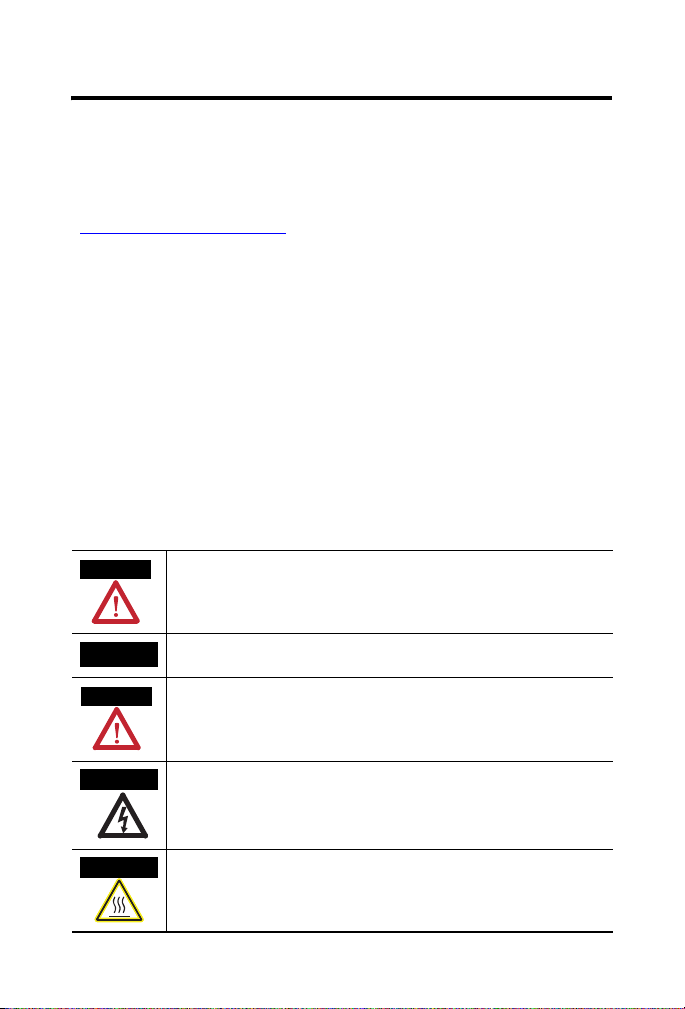
Throughout this manual, when necessary, we use notes to make you aware of safety considerations.
WARNING
Identifies information about practices or circumstances that can cause an explosion in
a hazardous environment, which may lead to personal injury or death, property
damage, or economic loss.
IMPORTANT
ATTENTION
SHOCK HAZA
BURN HAZAR
Publication
Identifies information that is critical for successful application and understanding of
the product.
Identifies information about practices or circumstances that can lead to personal
injury or death, property damage, or economic loss. Attentions help you identify a
hazard, avoid a hazard and recognize the consequences.
Labels may be located on or inside the equipment (for example, drive or motor) to
alert people that dangerous voltage may be present.
Labels may be located on or inside the equipment (for example, drive or motor) to
alert people that surfaces may be dangerous temperatures.
1732D-IN011A-EN-E - April 2009
Page 3
DeviceNet ArmorBlock Network and Auxiliary Powered Module, Series A 3
Environment and Enclosure
ATTENTION
This equipment is intended for use in overvoltage Category II applications (as
defined in IEC
This equipment is considered Group 1, Class A industrial equipment according
to IEC/CISPR
with electromagnetic compatibility in residential and other environments due
to conducted and radiated disturbances.
This equipment is supplied as enclosed equipment. It should not require
additional system enclosure when used in locations consistent with the
enclosure type ratings stated in the Specifications section of this publication.
Subsequent sections of this publication may contain additional information
regarding specific enclosure type ratings, beyond what this product provides,
that are required to comply with certain product safety certifications.
In addition to this publication, see:
• Industrial Automation Wiring and Grounding Guidelines, Allen-Bradley
• NEMA Standards 250 and IEC 60529, as applicable, for explanations of
60664-1), at altitudes up to 2000 m (6562 ft) without derating.
11. Without appropriate precautions, there may be difficulties
publication 1770-4.1
the degrees of protection provided by different types of enclosure.
, for additional installation requirements.
Prevent Electrostatic Discharge
ATTENTION
This equipment is sensitive to electrostatic discharge, which can cause
internal damage and affect normal operation. Follow these guidelines when
you handle this equipment.
• Touch a grounded object to discharge potential static.
• Wear an approved grounding wriststrap.
• Do not touch connectors or pins on component boards.
• Do not touch circuit components inside the equipment.
• Use a static-safe workstation, if available.
• Store the equipment in appropriate static-safe packaging when not in
use.
Publication
1732D-IN011A-EN-E - April 2009
Page 4
4 DeviceNet ArmorBlock Network and Auxiliary Powered Module, Series A
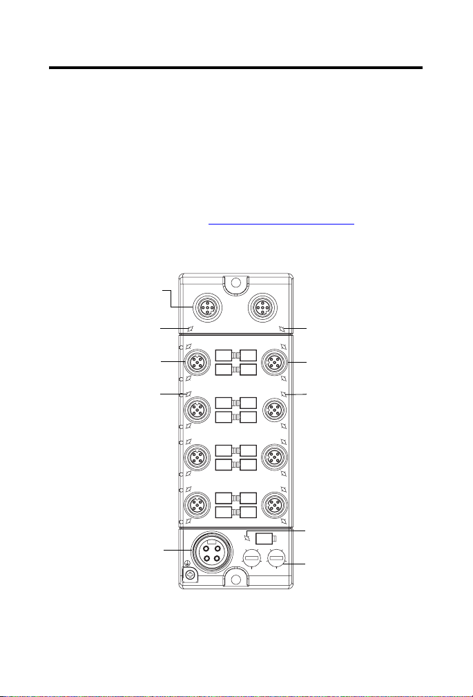
About the Module
The DeviceNet 1732D ArmorBlock I/O family consists of stand-alone
24V DC I/O modules that communicate via the DeviceNet network. The
sealed IP69K housing of these modules requires no enclosure. Note that it is
possible that environmental requirements other than IP69K require an
additional appropriate enclosure. I/O connectors are sealed M12 style.
The DeviceNet network uses advanced network technology,
producer/consumer communication, to increase network functionality and
throughput. Visit our web site at
producer/consumer technology information and updates.
http://www.ab.com/networks for
M12-style DeviceNet
connector
Module status indicator
M12-style
input connector (4)
Input status indicator (8)
M18-style auxiliary
power connector
Publication
1732D-IN011A-EN-E - April 2009
DNet In DNet Out
I - 0
I - 1
I - 2
I - 3
I - 4
I - 5
I - 6
I - 7
P
W
R
8
66
NETMOD
O - 0
O - 1
O - 2
O - 3
O - 4
O - 5
O - 6
O - 7
00
2
2
8
4
4
X10 X1
Network status indicator
M12-style output connector
Output status indicator (8)
Auxiliary power status
indicator
Node address
44763
Page 5

DeviceNet ArmorBlock Network and Auxiliary Powered Module, Series A 5
Catalog Number Explanation
The catalog number 1732D-8X81212HD identifies a DeviceNet 24V DC
8-port 8-input 8-output 1.4 A M12-style network connector module.
Install the Module
To install the module:
• Set the node address
• Mount the module
• Connect the cord sets
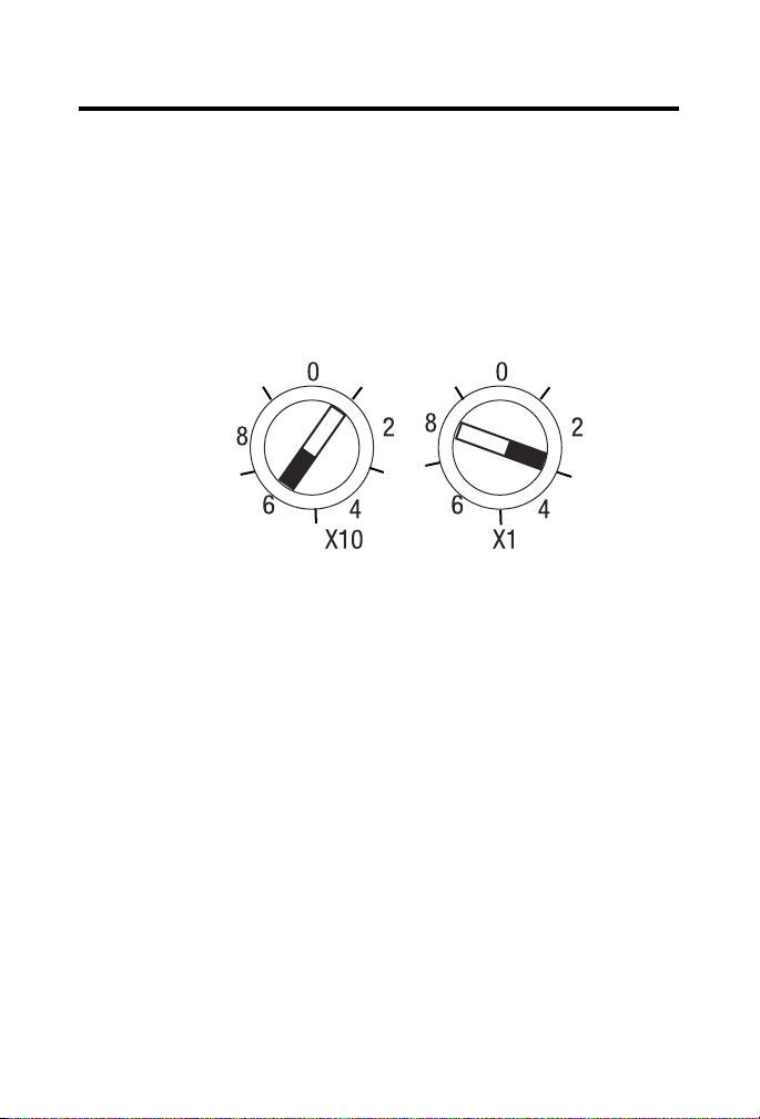
Set the Node Address
Valid node addresses are 00 through 63.
Set the node address using either the rotary switches, RSNetWorx for
DeviceNet, DeviceNetManager, or another software configuration tool.
Setting the switches at any number from 64 through 99 lets the software have
address control.
Each module is shipped set for node address 63. Remove the caps on the
front of the module to access the switches. The two switches are:
• X10 (most significant digit) - left side of module
• X1 (least significant digit) - right side of module
Publication
1732D-IN011A-EN-E - April 2009
Page 6
6 DeviceNet ArmorBlock Network and Auxiliary Powered Module, Series A
To reset the node address:
1. Rotate the switches using a small blade screwdriver.
2. Line up the small black dot on the switch with the number setting you
wish to use.
3. Cycle power.
Example shows
default node
address set at 63.
43968
The rotary switches are read periodically. If the switches have been changed
since the last time they were read and they no longer match the online address,
a minor fault occurs, which is indicated by a flashing red MOD LED.
Settings of 64 through 99 cause the module to use the last valid node address
stored internally. For example, the last setting internally was 40. If a change is
made to 68, and then you power up, the address defaults to 40.
The module is equipped with AutoBaud detect. AutoBaud lets the module
read the settings already in use on your DeviceNet network and automatically
adjusts to those settings.
Mount the Module
Two sets of mounting holes are used to mount the module directly to a panel
or machine. Mounting holes accommodate #6 (M3) pan head screws. The
torque specification is 0.64 Nm (6 in-lb).
Publication
1732D-IN011A-EN-E - April 2009
Page 7
DeviceNet ArmorBlock Network and Auxiliary Powered Module, Series A 7
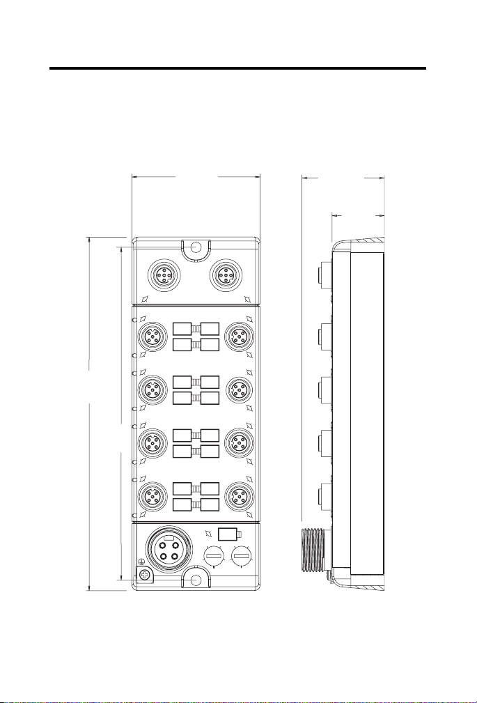
Product Dimensions
Refer to the mounting dimensions illustration to help you mount the module.
Module Dimensions
179 mm
(7.05 in.)
169 mm
(6.64 in.)
65 mm
(2.56 in.)
DNet In DNet Out
I - 0
I - 1
I - 2
I - 3
I - 4
I - 5
I - 6
I - 7
P
W
R
8
66
Front view
NETMOD
O - 0
O - 1
O - 2
O - 3
O - 4
O - 5
O - 6
O - 7
00
2
2
8
4
4
X10 X1
43.25 mm
(1.70 in.)
26.5 mm
(1.04 in.)
44799
Side view
Publication
1732D-IN011A-EN-E - April 2009
Page 8
8 DeviceNet ArmorBlock Network and Auxiliary Powered Module, Series A
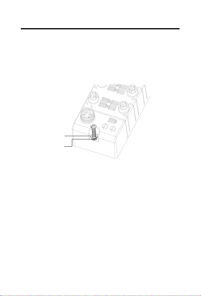
Mounting the Module in High Vibration Areas
If you mount the module in an area that is subject to shock or vibration,
we recommend that you use a flat and a lock washer to mount the module.
Mount the flat and the lock washer as shown in the mounting illustration.
Torque the mounting screws to 0.64 Nm (6 in-lb).
Lock washer
Flat washer
44766
Connect the I/O Cord Sets to the ArmorBlock Module
The ArmorBlock DeviceNet family has 5-pin M12-style connectors.
We provide caps to cover the unused connectors on your module.
Connect the quick-disconnect cord sets that you selected for your module to
the appropriate ports.
Publication
1732D-IN011A-EN-E - April 2009
Page 9

DeviceNet ArmorBlock Network and Auxiliary Powered Module, Series A 9
Network Connector
Refer to the pinout diagram for the network connector.
M12-style Input Connectors
Male Female
(View into Connector)
Pin 1 Drain
Pin 2 V+ (Red)
Pin 3 V- (Black)
Pin 4 CAN_H (White)
Pin 5 CAN_L (Blue)
I/O Connectors
Refer to the pinout diagrams for the I/O connectors.
M12-style 5-pin Female Input Connectors
(View into Connector)
Pin 1 Sensor Source Voltage
Pin 2 Input B
Pin 3 Return
Pin 4 Input A
41452
Pin 5 PE
4145244175
M12-style 5-pin Female Output Connector
(View into Connector)
Pin 1 Not Used
Pin 2 Output B
Pin 3 Return
Pin 4 Output A
41452
Pin 5 PE
Publication
1732D-IN011A-EN-E - April 2009
Page 10

10 DeviceNet ArmorBlock Network and Auxiliary Powered Module, Series A
Auxiliary Power Cable
Refer to the pinout diagram to attach auxiliary power.
M18-style 4-pin Male Auxiliary Power Connector
(View into Connector)
4
3
2
1
43906
Refer to publication M116-CA001 for Rockwell Automation cable and cord
set offerings or access the Connection Systems website at
http://www.ab.com/sensors/products/connection_systems/.
Pin 1 Output Power+
Pin 2 No Connection
Pin 3 No Connection
Pin 4 Output Power-
ATTENTION
ATTENTION
Publication
If any I/O devices connected to this equipment require Class 2 power to
operate, this equipment and all connected I/O must be powered by a Class 2
source.
To comply with the CE Low Voltage Directive (LVD), this equipment and all
connected I/O must be powered from a source compliant with the following:
Safety Extra Low Voltage (SELV) or Protected Extra Low Voltage (PELV).
Make sure all connectors and caps are securely tightened to properly seal the
connections against leaks and maintain IP enclosure type requirements.
1732D-IN011A-EN-E - April 2009
Page 11

DeviceNet ArmorBlock Network and Auxiliary Powered Module, Series A 11
Communicate with Your Module
This module’s I/O is exchanged with the master through a cyclic, polled, or
change-of-state connection.
Cyclic - allows configuration of the block as an I/O client. The block will
produce and consume its I/O cyclically at the rate configured.
Polled - a master initiates communication by sending its polled I/O message
to the module. The module consumes the message, updates outputs, and
produces a response. The response has input data.
Change-of-State - productions occur when an input changes or a fault
condition occurs. If no input or fault condition change occurs within the
expected packet rate, a heartbeat production occurs. This heartbeat
production tells the scanner module that the I/O module is alive and ready to
communicate. Consumption occurs when data changes and the master
produces new output data to the I/O block.
Refer to the Module Data Definitions table for more information.
1732D-8X81212HD Data Definitions
Byte Bit 7 Bit 6 Bit 5 Bit 4 Bit 3 Bit 2 Bit 1 Bit 0
Produce 0 I7 I6 I5 I4 I3 I2 I1 I0
Produce 1 In Short Out Short
Consume 0 O7 O6 O5 O4 O3 O2 O1 O0
Where: I=Input Data; 0=Off, 1=On
In Short 0=Working, 1=Sensor Source Voltage Fault
Out Short 0=Working, 1=Output Fault (Short)
O=Output Data; 0=Off, 1=On
Publication
1732D-IN011A-EN-E - April 2009
Page 12

12 DeviceNet ArmorBlock Network and Auxiliary Powered Module, Series A
Interpret the Status Indicators
This module has the following status indicators:
• Network and Module status indicators for DeviceNet
• Auxiliary Power indicator
• Individual I/O status indicators for inputs and outputs
DNet In DNet Out
Module status
indicator
Input status
indicators
NETMOD
I - 0
I - 1
I - 2
O - 0
O - 1
O - 2
Network status
indicator
Output status
indicators
Auxiliary power
status indicator
44763
P
W
00
R
2
8
8
66
4
X10 X1
O - 3
O - 4
O - 5
O - 6
O - 7
2
4
I - 3
I - 4
I - 5
I - 6
I - 7
Publication
1732D-IN011A-EN-E - April 2009
Page 13

DeviceNet ArmorBlock Network and Auxiliary Powered Module, Series A 13
Network Status
Status Description Recommended action
Off Device is not online. Wait until the device has
completed the dup_MAC_id test
or apply power to the device.
Green Device is operating normally and is
Flashing
Green
Red Critical link failure – failed
Flashing Red Recoverable fault – an I/O
online with connections in the
established state. As a Group 2
module, it means that the module is
allocated to a master.
Device is online with no connections
in the established state.
communication module.
connection has timed out.
None.
Establish connections to other
nodes. As a group 2 module,
allocate the module to a master.
Check your configuration and cycle
power.
Cycle power to the module.
Publication
1732D-IN011A-EN-E - April 2009
Page 14

14 DeviceNet ArmorBlock Network and Auxiliary Powered Module, Series A
Module Status
Status Description Recommended action
Off There is no power applied to the
device.
Green Device is operating normally. None.
Flashing
Green
Flashing Red Recoverable fault – input or output
Red Critical fault – device timed out or
Device needs commissioning due to
missing, incomplete, or incorrect
configuration.
short circuit.
has an unrecoverable fault.
Apply power to the device.
Check your configuration and cycle
power.
Check your input devices and
check your output devices and
cycle power.
Cycle power to the device. If that
does not fix the fault, contact your
Rockwell Automation
representative. The device may
need to be replaced.
Auxiliary Status
Status Description Recommended action
Off There is no auxiliary power applied
to the device.
Green There is auxiliary power applied to
the device.
Apply auxiliary power to the
device.
None.
I/O Status
Status Description Recommended action
Off Output is not energized or input is
not valid.
Yel low Output is energized or input is valid. None.
Publication
1732D-IN011A-EN-E - April 2009
None.
Page 15

DeviceNet ArmorBlock Network and Auxiliary Powered Module, Series A 15
Specifications
DeviceNet 1732 ArmorBlock Network Powered and Auxiliary Powered
Output Module, Series A - 1732D-8X81212HD Inputs
Attribute Valu e
Number of inputs 8
Off-state input voltage, max 5V DC
On-state input voltage, max 25V DC
On-state input voltage, nom 24V DC
On-state input voltage, min 11V DC
Sensor source voltage, max 25V DC
Sensor source voltage, min 11V DC
Off-state input current, max 1.5 mA @ 5V DC
On-state input current, max 5 mA @ 25V DC
Input delay time
OFF to ON
ON to OFF
(1)
Input OFF to ON or ON to OFF delay is time from a valid input signal to recognition by the module.
(1)
0…16000 μs
Publication
1732D-IN011A-EN-E - April 2009
Page 16

16 DeviceNet ArmorBlock Network and Auxiliary Powered Module, Series A
DeviceNet 1732 ArmorBlock Network Powered and Auxiliary Powered
Output Module, Series A - 1732D-8X81212HD Outputs
Attribute Valu e
Number of outputs 8
On-state output voltage drop, max 0.5V DC
Off-peak blocking voltage, min 30V DC
On-state output voltage, max 30V DC
On-state output voltage, min 11V DC
On-state output voltage, nom 24V DC
On-state output current, max 1.4 A
Current per module, max 8 A (all outputs)
Off-state output leakage current,
max
Surge current per output, max 3.2 A for 10 ms, repeatable every 2 s
50 μA
General Specifications
Attribute Valu e
Power consumption 2.0 W
Power dissipation 6.8 btu/h
Isolation voltage 50V (continuous), Basic Insulation Type, Outputs
and Output Power to System
No isolation between individual I/O channels,
between Sensor Power and Network, or between
Inputs and Network
Type tested at 707V DC for 60s
Auxiliary power voltage, max 30V DC
Auxiliary power voltage, min 12V DC
Auxiliary power current, max 8 A
DeviceNet power voltage, max 25V DC
Publication
1732D-IN011A-EN-E - April 2009
Page 17

DeviceNet ArmorBlock Network and Auxiliary Powered Module, Series A 17
General Specifications (Continued)
Attribute Value
DeviceNet power voltage, min 11V DC
DeviceNet current 100 mA plus sum of sensor currents
Sensor source current per module,
max
Communication rate 125 Kbps @ 500 m (1640 ft) for thick cable, flat
Pilot duty rating Not rated
Enclosure type rating Meets IP65/66/67/69K (when marked), and
Wiring category
(1)
Indicators 1 green/red module status
Dimensions (HxWxD), approx. 179 x 65 x 43.25 mm (7.05 x 2.56 x 1.70 in.)
Weight, approx. 0.392 kg (0.864 lb)
(1)
Use this Conductor Category information for planning conductor routing. Refer to Industrial
Automation Wiring and Grounding Guidelines, publication
500 mA
media length 375 m (1230 ft)
250 Kbps @ 200 m (600 ft) for thick cable, flat
media length 150 m (492 ft)
500 Kbps @ 100 m (330 ft) for thick cable, flat
media length 75 m (246 ft)
NEMA
4X/6P with receptacle dust caps or cable
termination
1 - on signal ports
1 - on power ports
2 - on communications ports
1 green/red network status
1 green auxiliary power status
8 yellow input status
8 yellow output status
1770-4.1.
Publication
1732D-IN011A-EN-E - April 2009
Page 18

18 DeviceNet ArmorBlock Network and Auxiliary Powered Module, Series A
Environmental Specifications
Attribute Value
Temperature,
operating
Temperature,
non-operating
Relative humidity IEC 60068-2-30 (Test Db, Unpackaged Damp Heat):
Vibration IEC 60068-2-6 (Test Fc, Operating):
Shock, operating IEC 60068-2-27 (Test Ea, Unpackaged Shock):
Shock,
non-operating
Emissions CISPR 11:
ESD immunity IEC 61000-4-2:
Radiated RF
immunity
IEC 60068-2-1 (Test Ad, Operating Cold),
IEC 60068-2-2 (Test Bd, Operating Dry Heat),
IEC 60068-2-14 (Test Nb, Operating Thermal Shock):
-20…60 °C (-4…140 °F)
IEC 60068-2-1 (Test Ab, Unpackaged Non-operating Cold),
IEC 60068-2-2 (Test Bb, Unpackaged Non-operating Dry Heat),
IEC 60068-2-14 (Test Na, Unpackaged Non-operating Thermal
Shock):
-45…85 °C (-49…185 °F)
5…95% non-condensing
5 g @ 10…500 Hz
30 g
IEC 60068-2-27 (Test Ea, Unpackaged Shock):
50 g
Group 1, Class A
8 kV contact discharges
8 kV air discharges
IEC 61000-4-3:
10V/m with 1 kHz sine-wave 80% AM from 80…2000 MHz
10V/m with 200 Hz 50% Pulse 100% AM at 900 MHz
10V/m with 200 Hz 50% Pulse 100% AM at 1890 MHz
1V/m with 1 kHz line-wave 80% AM from 2000…2700 MHz
Publication
1732D-IN011A-EN-E - April 2009
Page 19

DeviceNet ArmorBlock Network and Auxiliary Powered Module, Series A 19
Environmental Specifications (Continued)
Attribute Value
EFT/B Immunity IEC 61000-4-4:
±3 kV at 5 kHz on power ports
±3 kV at 5 kHz on signal ports
±2 kV at 5 kHz on communications ports
Surge transient
immunity
Conducted RF
immunity
IEC 61000-4-5:
±1 kV line-line(DM) and ±2 kV line-earth(CM) on power ports
±1 kV line-line(DM) and ±2 kV line-earth(CM) on signal ports
±2 kV line-earth(CM) on communications ports
IEC 61000-4-6:
10V rms with 1 kHz sine-wave 80% AM from 150 kHz…80 MHz
Publication
1732D-IN011A-EN-E - April 2009
Page 20

20 DeviceNet ArmorBlock Network and Auxiliary Powered Module, Series A
Certifications
Certification (when
product is marked)
Value
(1)
c-UL-us UL Listed Industrial Control Equipment, certified for US and
Canada. See UL File E322657.
CE European Union 2004/108/EC EMC Directive, compliant with:
EN 61326-1; Meas./Control/Lab., Industrial Requirements
EN 61000-6-2; Industrial Immunity
EN 61000-6-4; Industrial Emissions
EN 61131-2; Programmable Controllers (Clause 8,
Zone A & B)
C-Tick Australian Radiocommunications Act, compliant with:
AS/NZS CISPR 11; Industrial Emissions
ODVA ODVA conformance tested to DeviceNet specifications
(1)
See the Product Certification link at http://www.ab.com for Declarations of Conformity, Certificates,
and other certification details.
Publication
1732D-IN011A-EN-E - April 2009
Page 21

DeviceNet ArmorBlock Network and Auxiliary Powered Module, Series A 21
Notes:
Publication
1732D-IN011A-EN-E - April 2009
Page 22

22 DeviceNet ArmorBlock Network and Auxiliary Powered Module, Series A
Notes:
Publication
1732D-IN011A-EN-E - April 2009
Page 23

DeviceNet ArmorBlock Network and Auxiliary Powered Module, Series A 23
Notes:
Publication
1732D-IN011A-EN-E - April 2009
Page 24

Rockwell Automation Support
Rockwell Automation provides technical information on the Web to assist you in using
its products. At http://support.rockwellautomation.com
, you can find technical
manuals, a knowledge base of FAQs, technical and application notes, sample code and
links to software service packs, and a MySupport feature that you can customize to
make the best use of these tools.
For an additional level of technical phone support for installation, configuration, and
troubleshooting, we offer TechConnect support programs. For more information,
contact your local distributor or Rockwell Automation representative, or visit
http://support.rockwellautomation.com
.
Installation Assistance
If you experience a problem within the first 24 hours of installation, please review the
information that's contained in this manual. You can also contact a special Customer
Support number for initial help in getting your product up and running.
United States 1.440.646.3434
Outside United States Please contact your local Rockwell Automation representative for any
Monday – Friday, 8 a.m. – 5 p.m. EST
technical support issues.
New Product Satisfaction Return
Rockwell Automation tests all of its products to ensure that they are fully operational
when shipped from the manufacturing facility. However, if your product is not
functioning and needs to be returned, follow these procedures.
United States Contact your distributor. You must provide a Customer Support case number
Outside United States Please contact your local Rockwell Automation representative for the return
Allen-Bradley, ArmorBlock, RSNetWorx for DeviceNet, DeviceNetManager, Rockwell Automation, and
TechConnect are trademarks of Rockwell Automation, Inc.
Trademarks not belonging to Rockwell Automation are property of their respective companies.
(see phone number above to obtain one) to your distributor in order to
complete the return process.
procedure.
Publication 1732D-IN011A-EN-E - April 2009 PN-43627
Copyright © 2009 Rockwell Automation, Inc. All rights reserved.
 Loading...