

Page 1

160-PD1
Profibus-DP
Communication
Module
Catalog Number: 160-PD1
Firmware: 1.00
User Manual
Page 2
Importa nt U ser Information
Solid state equipment has operationa l characteristics differing from those of
electromechanical equipment. “Safety Guidelines for the Application,
Installation and Maintenance of Solid Stat e Contr ols” (Publication SGI-1.1)
describe s s ome important differences be t ween solid state equipment and
hard-wi red el ect ro mechanical d evices . Becau s e of th i s d i fferen ce, and also
because of the wide variety of uses for solid state equipment, all p ers ons
responsible for applyin g t his equipment must sat isf y t hemselves that each
intended application of this equipment is acceptable.
In no event will Rockwell Automation be responsible or liable for indirect
or consequential damages resulting from the use or application of this
equipment.
The examples and diagra m s i n t h i s manual are included solely for
illustrati ve purposes. Because of t he man y v ariables and requirements
associated w ith any particular installation, Rockwell Automation cannot
assume responsibility or liability for actual use based on the examples and
diagrams.
No patent liability is assumed by Rockwell Automation with respect to use
of information, circuits, equi pment, or software described in this manual.
Reproduction of the contents of this manual, in whole or in part, without
written permission of Rockwell Automation is prohibited.
Throughout this manual we use notes to make you aware of safety
considerations.
ATTENTION: Identifies information about practices or
circumstances that can lead to personal injury or death,
!
property damage , or ec onomic loss.
Attentions help you:
• identify a hazard
• avoid the hazard
• recognize the consequences
Important: Identifie s information that is especially important for success ful
application and understanding of the product.
Shock Ha za r d labels may be loca ted on or in side the dri v e
to alert p eo p l e that dan g ero u s vol ta g e m ay b e present.
MicroLogix and SLC are trademarks of Rockwell Automation.
PLC and PLC-5 are registered trademarks of Rockwell Automation.
RSLinx and RSLogix 500 are trademarks of Rockwell Software, Inc.
Windows and Windows NT are registered trademarks of Microsoft Corporation
Profibus is a registered trademark of the Profibus Trade Organisation
Page 3

Using This Manual
Product Overview
Quick Start for Experienced
Users
Ins tallation and Wiring
Table of Contents
Preface
Who Should Use This Manual? . . . . . . . . . . . . . . . . . . . . . . . . . . . . . . . . . p-i
Conventions . . . . . . . . . . . . . . . . . . . . . . . . . . . . . . . . . . . . . . . . . . . . . . . . p-i
PD1 Compatibility . . . . . . . . . . . . . . . . . . . . . . . . . . . . . . . . . . . . . . . . . . . . p-i
Reference Manuals. . . . . . . . . . . . . . . . . . . . . . . . . . . . . . . . . . . . . . . . . . p-ii
Safety Precautions . . . . . . . . . . . . . . . . . . . . . . . . . . . . . . . . . . . . . . . . . . p-ii
Chapter 1
Module Description. . . . . . . . . . . . . . . . . . . . . . . . . . . . . . . . . . . . . . . . . . 1-1
Configuration Rotary Switches . . . . . . . . . . . . . . . . . . . . . . . . . . . . . . . 1-2
Chapter 2
Required Tools and Equipment. . . . . . . . . . . . . . . . . . . . . . . . . . . . . . . . . 2-1
Procedures . . . . . . . . . . . . . . . . . . . . . . . . . . . . . . . . . . . . . . . . . . . . . . . . 2-2
Chapter 3
EMC Directive 89/336/EEC Compliance. . . . . . . . . . . . . . . . . . . . . . . . . . 3-1
Low Voltage Directive 73/23/EEC Compliance . . . . . . . . . . . . . . . . . . . . . 3-1
Profibus-DP Configuration . . . . . . . . . . . . . . . . . . . . . . . . . . . . . . . . . . . . 3-2
Module Configuration Switches . . . . . . . . . . . . . . . . . . . . . . . . . . . . . . . . 3-2
Setting the node address – S1 & S2 . . . . . . . . . . . . . . . . . . . . . . . . . . .3-2
Module Installation/Removal. . . . . . . . . . . . . . . . . . . . . . . . . . . . . . . . . . . 3-3
Keypad or Ready/Fault Panel Removal . . . . . . . . . . . . . . . . . . . . . . . . . 3-3
Installing the PD1 Module . . . . . . . . . . . . . . . . . . . . . . . . . . . . . . . . . . . 3-3
Removing the PD1 Module . . . . . . . . . . . . . . . . . . . . . . . . . . . . . . . . . . 3-4
Wiring the Drive Terminal Block . . . . . . . . . . . . . . . . . . . . . . . . . . . . . . . . 3-5
Wiring the PD1 Ground Terminal . . . . . . . . . . . . . . . . . . . . . . . . . . . . . . . 3-6
Wiring the Connector . . . . . . . . . . . . . . . . . . . . . . . . . . . . . . . . . . . . . . . . 3-7
Connecting the Communication Cable to the Module. . . . . . . . . . . . . . . . 3-8
Profibus Network Termination. . . . . . . . . . . . . . . . . . . . . . . . . . . . . . . . . . 3-8
Modes of Operation
Chapter 4
Powering Up the Drive . . . . . . . . . . . . . . . . . . . . . . . . . . . . . . . . . . . . . . . 4-1
LED Indicators . . . . . . . . . . . . . . . . . . . . . . . . . . . . . . . . . . . . . . . . . . . . . 4-1
Operation Modes . . . . . . . . . . . . . . . . . . . . . . . . . . . . . . . . . . . . . . . . . . . 4-2
Power-up Mode . . . . . . . . . . . . . . . . . . . . . . . . . . . . . . . . . . . . . . . . . . . 4-2
Run Mode . . . . . . . . . . . . . . . . . . . . . . . . . . . . . . . . . . . . . . . . . . . . . . . 4-2
Error Mode . . . . . . . . . . . . . . . . . . . . . . . . . . . . . . . . . . . . . . . . . . . . . . . 4-2
Page 4

ii
Profibus Parameter
Descriptions and Data Protocol
Using the 160-PD1 on Profibus
Chapter 5
160 SSC Drive Parameters . . . . . . . . . . . . . . . . . . . . . . . . . . . . . . . . . . . . 5-1
Data from Profibus-DP Master to PD1 Slave. . . . . . . . . . . . . . . . . . . . . . . 5-2
Data from PD1 Slave to Profibus-DP Master. . . . . . . . . . . . . . . . . . . . . . 5-2
Control and Status Word PROFIDRIVE. . . . . . . . . . . . . . . . . . . . . . . . . . . 5-3
State Transitions. . . . . . . . . . . . . . . . . . . . . . . . . . . . . . . . . . . . . . . . . . . . . 5-4
Parameter Operation . . . . . . . . . . . . . . . . . . . . . . . . . . . . . . . . . . . . . . . . . 5-4
Parameter Access . . . . . . . . . . . . . . . . . . . . . . . . . . . . . . . . . . . . . . . . . . . 5-5
Parameter attributes . . . . . . . . . . . . . . . . . . . . . . . . . . . . . . . . . . . . . . . 5-5
Parameter Access Status . . . . . . . . . . . . . . . . . . . . . . . . . . . . . . . . . . . 5-5
Chapter 6
Required Tools. . . . . . . . . . . . . . . . . . . . . . . . . . . . . . . . . . . . . . . . . . . . . . 6-1
Create a Profibus Network Configuration Frame . . . . . . . . . . . . . . . . . . . . 6-2
Installing the 160-PD 1 G SD File in the Software Tool Library . . . . . . . . . . 6-2
Configuring the SST-PFB-SLC Scanner. . . . . . . . . . . . . . . . . . . . . . . . . . . 6-4
Summary of the Example Scanner Con figuration . . . . . . . . . . . . . . . . . . . 6-8
Setting up the SST-PFB-SLC Scanner Card to work in the SLC . . . . . . . . 6-9
SLC Ladder Logic Example. . . . . . . . . . . . . . . . . . . . . . . . . . . . . . . . . . . 6-11
Controlling the Drive. . . . . . . . . . . . . . . . . . . . . . . . . . . . . . . . . . . . . . . . . 6-13
The Profibus Telegram. . . . . . . . . . . . . . . . . . . . . . . . . . . . . . . . . . . . . . . 6-16
Controlling the Drive
Troubleshooting
Specifications
Chapter 7
Setting the Drive to Enable Network Control . . . . . . . . . . . . . . . . . . . . . . . 7-1
Setting the Node Address . . . . . . . . . . . . . . . . . . . . . . . . . . . . . . . . . . . . . 7-1
Chapter 8
Setup . . . . . . . . . . . . . . . . . . . . . . . . . . . . . . . . . . . . . . . . . . . . . . . . . . . . . 8-1
LED Indicators and Troubleshooting . . . . . . . . . . . . . . . . . . . . . . . . . . . . . 8-1
READY LED . . . . . . . . . . . . . . . . . . . . . . . . . . . . . . . . . . . . . . . . . . . . . 8-1
COMM LED . . . . . . . . . . . . . . . . . . . . . . . . . . . . . . . . . . . . . . . . . . . . . 8-2
FAULT LED . . . . . . . . . . . . . . . . . . . . . . . . . . . . . . . . . . . . . . . . . . . . . . 8-2
Appendix A
Electrical . . . . . . . . . . . . . . . . . . . . . . . . . . . . . . . . . . . . . . . . . . . . . . . . . A-1
Environmental . . . . . . . . . . . . . . . . . . . . . . . . . . . . . . . . . . . . . . . . . . . . . A-1
Communications . . . . . . . . . . . . . . . . . . . . . . . . . . . . . . . . . . . . . . . . . . . A-1
Mechanical. . . . . . . . . . . . . . . . . . . . . . . . . . . . . . . . . . . . . . . . . . . . . . . . A-1
Index
Page 5

Preface
Using This Manual
The purpose of this manual is to provide you with the necessary
informatio n t o apply the Bull et i n 160-P D 1 C ommunication Module.
Described in this manual are methods for installing, configuring, and
troubleshooting the 160-PD1 Profibus Communications Module.
For information on specific drive features, refer to the 160 SSC™
Variable Speed Drive (Series C) User Manual.
Important: Read this manual in its entirety before installing,
operating, servicing, or initializing the PD1 Module.
Who Should Use This Manual?
Conventions
PD1 Compatibility
This manual is intended f or qua lif ied pe rsonnel. To make ef ficient use
of the Communication Module, you must be able to program and
operate Profibus communications devices, as well as have an
understan d ing of the paramete r settings and functions of the 160
Drive.
In this manual we refer to the:
• 160-PD1 Communication Module as Communication Module,
PD1 Module or Module.
• 160 SSC Adjustable Fr equency AC Dri ve as the 160 Drive or
drive.
In addition, parameter numbers and names (both 160 Drive and PD1
Module) are shown in bold typeface and follow the format PXX - [*]
where P denotes parameter, XX denotes the two digit parameter
number, and * represents the parameter name.
For example, P01 - [Output Frequency].
The PD1 Module is compatible only with 160 Drives Series C or
above. When properly connected, the module communicates via a
Profibus-DP network.
Page 6
p–ii Preface
Reference Manuals
For Read This Document
Additional information about networking and the SLC™ 500 SLC 500 Modular Hardware Style Manual 1747-6.2
Information about the AIC+ AIC+ Advanced Interface Converter User Manual 1761-6.4
Instruction set information for the SLC 500 and MicroLogix™ 1000 SLC 500 and MicroLogix 1000 Instru ction Set Reference Manual 1747-6.15
For general MicroLogix 1000 information MicroLogix 1000 User Manual 1761-6.3
For 160 SSC Drive Information: 160 SSC Variable Speed Drive (Series C) User Manual 0160-5.17ML
A complete listing of current Allen-Bradley documentation, including ordering instructions. Also indicates whether the documents
are available on CD-ROM or in multi-languages.
A glossary of industrial automation terms and abbreviations Allen-Bradley Industrial Automation Glossary AG-7.1
Information about the SSC-PFB-SLC™ Scanner Scanner Card User Manual. SST Woodhead documentation can
The following documents contai n addit ional informat ion concernin g
Allen-Br ad ley p r oduc t s. T o obt ain a copy, contac t your local
Allen-Bradle y Sales Off ice or visit the “On-Line Publications” ar ea of
the Allen-Bradley Internet home page at: www.ab.com..manuals.
Publication
Number
Allen-Bradley Publication Index SD499
Version 1.0
be obtained online at http://www.mySST.com/download/
Safet y Precautions
ATTENTION: Only personnel familiar wit h 160 Drives,
Communication Modules and associated machinery should
!
plan or implement the installation, start-up, configuration
and subsequent maintenance of this module. Failure to
comply may result in personal injury and/or equipment
damage.
ATTENTION: This module contains ESD (Electrostatic
Discharge) sensitive parts and assemblies. Static control
!
precautions ar e required when insta lling, testi ng, servicing,
or repairing this ass embly. Component damage may result
if ESD control procedures are not fol lowed. If you are not
familiar with static control procedures, reference
Allen-Bradley Publication 8000-4.5.2, Guarding Against
Electrostatic Damage or any other applicable ESD
protection handbook.
ATTENTION: The driv e contains high volt age capacitors
which take time to di scharge after remov al of AC line po wer.
!
Before instal ling or removing the Communication Module,
ensure isolation of mains supply from line inputs R, S, T
(L1, L2, L3). W ait the r ecommended amount of ti me for the
capacitors to discharge to safe voltage levels (refer to the
160 SSC™ Variable Speed Drive (Series C) User Manual
for recommended time). Failure to do so may result in
personal injury or death.
ATTENTION: When a system is config ured for t he f irst
time, the motor must be disconnected from the machine or
!
process during initia l system testing. Ha zard of injury or
equipment damage may occur due to unintended or
incorrect m achi n e mo tion .
Page 7
Product Overview
This chapter contains the following information:
• The physical layout of the module.
• Location of configuration switches.
• Overview and components.
Chapter
1
Module Description
The PD1 Module is an optional int erfa ce de v ice design ed to pr ovide a
direct, digital l i nk between a Profibus Master an d th e 160 Drive. The
module connects to the drive through the expansion/keypad port on
the front of the drive. Refer to Fig u res 1 .1 and 1.2 fo r gen eral la yout
of the module and Chapters 4 or 8 for details on t h e LED indicators.
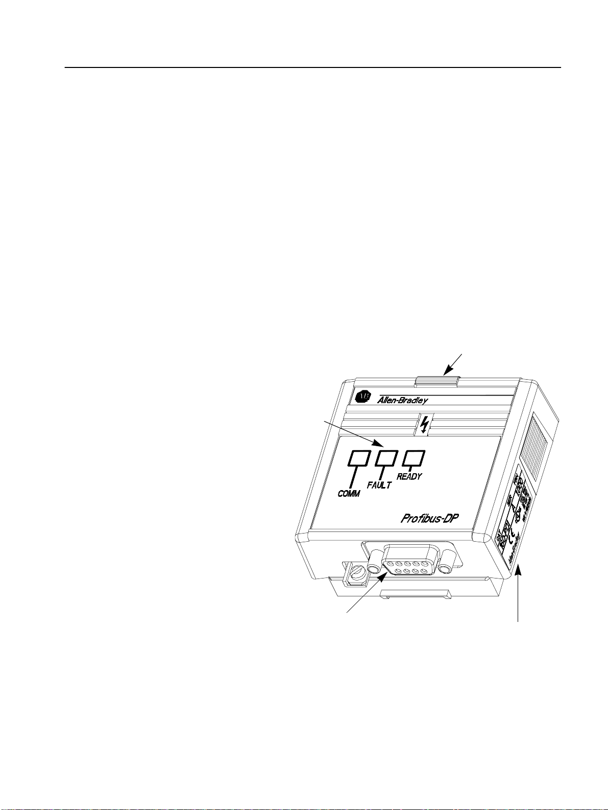
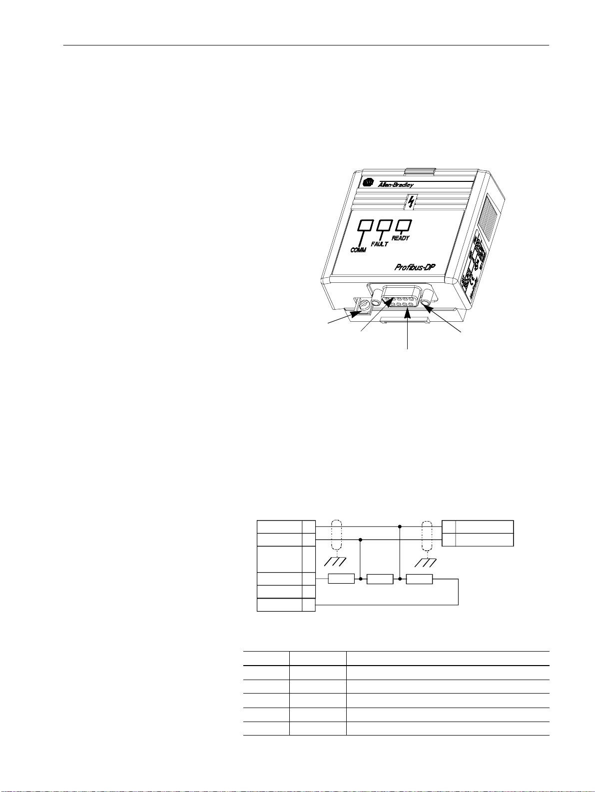
Figure 1.1
Module Front View
Module Installation Latch
Status LEDs
Refer to Chapters 4 & 8
for Further Information
9 Pin, Female D-Shell Connector
Refer to Chapter 3 for Details
Nameplate
Provides Firmware Version
and Series Letter
Page 8
1–2 Product Overview
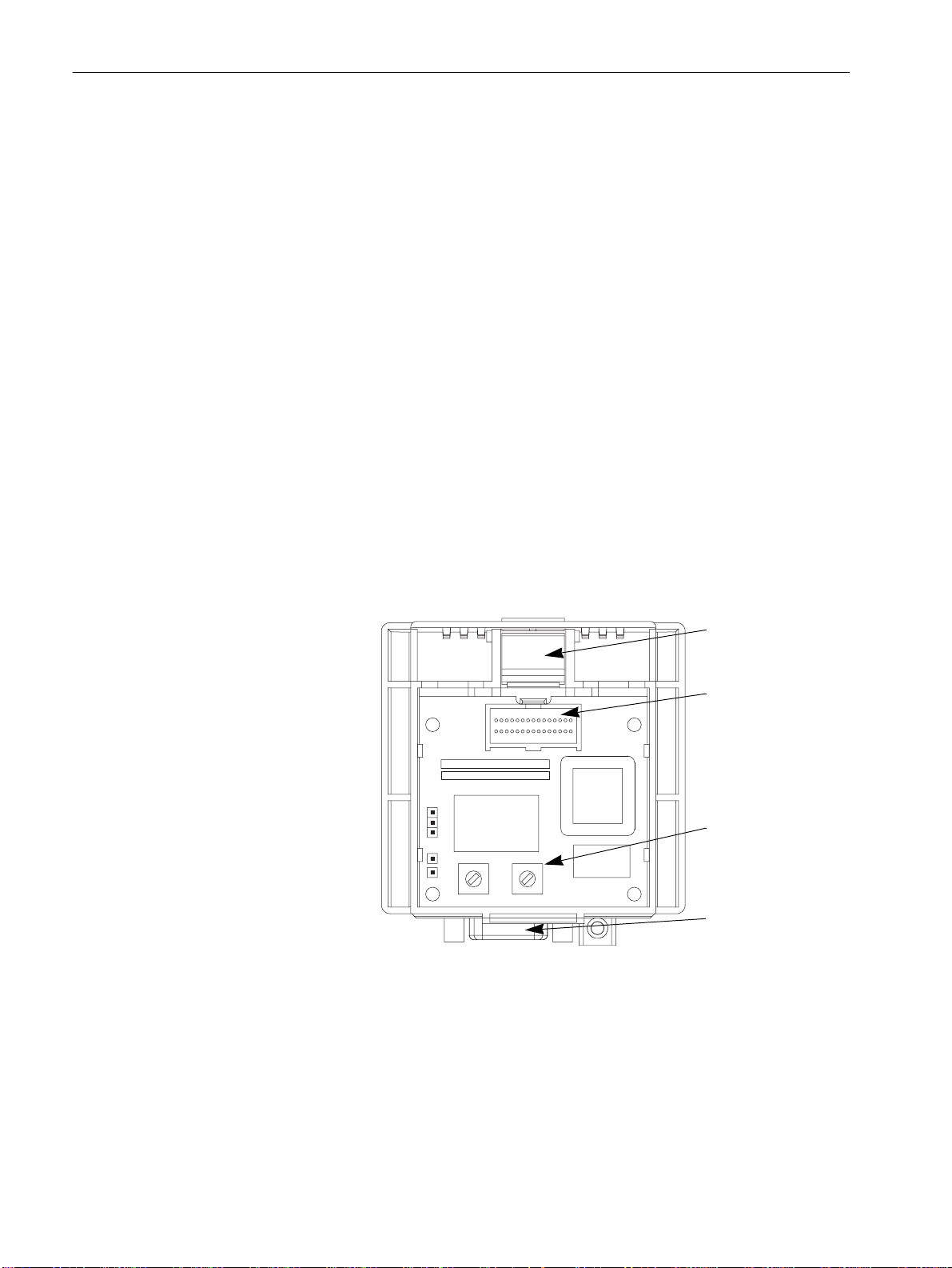
Configuration Rotary Switches
The Communication Module has two ten position rotary switches for
setting the node address. Rotary switches are located on the rear of
the module (see below) and are only accessible when the module is
removed from the 160 Drive. Refer to Chapter 3 for switch
configuration information.
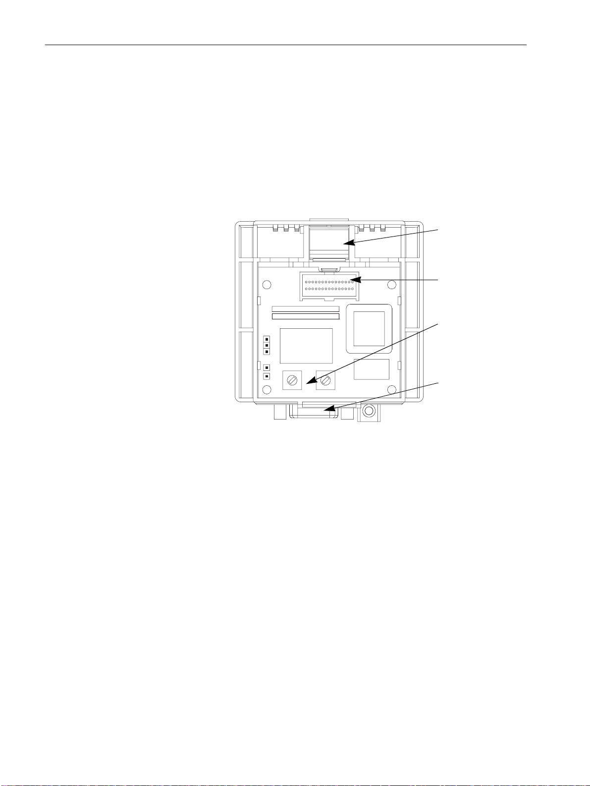
Figure 1.2
Module Rear View
Module Latch
Expansion/Keypad
P ort Connector
Rotary Switches
S1(left) - S2 (right)
D-Shell Connector
Page 9

Chapter
2
Quick Start for Experienced Users
This chapter can help you start using the PD1 Communication
Module. If you have installed or configured a network previously and
are familiar with Allen-Bradley communication modules and drives,
this informat ion c an he lp re d u ce the time o f insta llation. I f you are
uncertain, use the full installation/configuration information
beginning in Chapter 3.
We base the procedures here on the assumption that you understand
the basic concepts, know how to program the 160 Drive and
understand electronic process control.
Because it is a start-up guide for experienced users, this chapter does
not contain detailed explanations about the procedures listed. It does,
however, reference other chapters in this book where you can find
more information.
If you have any questions or are unfamiliar with the terms used or
concepts presented in the procedural steps, always read the
referenced chapters and other recommended do cu mentation b efore
trying to apply the information.
Required Tools and Equipment
This chapter contains the following information:
• What tools and equipment you need.
• When to address the module and program the drive to recognize
the module.
• How to install and wire the Communication Module.
• System power-up procedures.
Have the following tools and equipment ready:
• 3.2 mm (1/8 in.) flat blade screwdriver.
• GSD configuration file (see Page 3-2)
Page 10

2–2 Quick Start for Experienced Users
Procedures
Step Action
10. Check for proper operation.
For Further Info rmation
1. Review Attention statements in the Preface.
Ensure that power to the 160 Drive has been removed. 160 Drive
2.
Verify that the 160 Drive is correctly installed and
3.
wired. Stop Input (TB3-7, TB3-8) must be jumpered
together to start drive.
Configure the 160 Drive for the PD1 Module so the
4.
drive can accept control logic and speed reference via
the network.
Set P46 - [Input Mode] to a value of “2” or “6” as described
in Table 6.A. Th is will co nfigu re the drive to acce pt the logic
commands from the network.
Note: If the value has to be changed, set P56 - [Reset
Functions] to “2” or reboot the drive.
Set P59 - [Frequency Select] to “1.” This will configure the
drive to accept speed commands from the network.
Set P66 - [RPM Scaling] for the RPM/Hz Scaling factor.
This allows theNetwork Reference to be in RPM.
Remove Program Keypad Module or Ready/Fault
5.
Indicati ng Panel from th e dri ve.
6. Set the PD1 Module’s node adress.
7. Install the PD1 Module.
Connect communication cable.
8.
Check correct cable termination (figure 3.7)
9. Power up the drive and the network.
Refer to…
User Manual
160 Drive
User Manual
Chapter 5
(Parameters)
Chapter 3
(Installation)
Chapter 3
(Installation)
Chapter 3
(Installation)
Chapter 3
(Installation)
Chapter 3
(Installation)
Page 11

Chapter
3
Installation and Wi ring
This chapter contains information needed to:
• Meet the requirements of the EMC and Low Voltage directives
for CE compliance.
• Remove a pre-i nstalled Program Keypad Module or Ready/ Fault
Indicating Panel.
• Configure and install the PD1 Module.
• Wire the communication cables.
• Remove the PD1 Module from the drive.
Read this chapter completely before you attempt to install or
configure your module. Before applying power, review the Attention
statements presented throughout this manual. Verify that all
connections are secure and that all selections are correct.
ATTENTION: Unpredictable operation may occur if you
fail to check connections and rotary switch settings for
!
compatibi l ity w i t h your applic a tion. U npre d icta b le
operation may result in personal injury, death, and
equipment damage.
EMC Directive 89/336/EEC Compliance
Low Voltage Directive 73/23/ EEC Compliance
This product complies with Electromagnetic Compatibility (EMC)
Directive 89/336/EEC when conforming with the following
installation requirements:
• The essential requirements for a conf orming EMC inst al lation for
the Bulletin 160 SSC are employed. Refer to the 160 SSC™
Variable Speed Drive (Series C) User Manual.
This produc t complies with Low Voltage Directive 73/23/E E C when
conforming with the following installation requirements:
• The essential requirements for a conforming Low Voltage
Directive installation for the Bulletin 160 SSC are employed.
Refer to the 160 SSC™ Variable Speed Drive (Series C) User
Manual.
• Review the Attention st atements in t h e P reface, and ot her areas
throughout this manual prior to installation o f the module.
Page 12
3–2 Installation and Wiring
Profibus-DP Configuration
Module Configuration Switches
From Profibus-DP point of view the Profibus-DP Slave (PDPS) node
is configured based on a data f ile (*.GSD) which conta ins information
of the size and data-structure of the PDPS.
The Master controls the data exchange to all connected slaves.
The slaves’ I/O data are mapped into memory inside the Master
according to the GSD configuration file.
The Profibus User Organization (PNO) registered the required
Profibus ID as: 0587h.
The GSD file is named: PD1_0587.GSD. It can be downloaded from
the Internet either vi a Allen Bradley Homepage under
http://www/ab.com/drives/Profibus/Index.html or P NO Homepage
under http://www/Profibus.com/downloads.html tha n GSD Libra ry
/ Rockwell Automation AG and Drives.
A micro floppy disk containing this GSD file is also available on
request from stock (RA catalog number: 160-GSD).
The PD1 Module utilizes two ten-position rotary switches (see figure
below) to configure the node address. These switches must be set to
match th e applic ati o n settings. Refer t o t he par ag ra p h s t ha t fo llow.
Figure 3.1
Rotary Switch Location (Back of Module)
Module Latch
Expansion/Keypad
Port Connector
Rotary Switches
S1 (left), S2 (right)
D-Shell Connector
Setting the node address – S1 & S2
Before configuring the PD1 module the node address has to be set.
This is done via two rotary switches (S1, S2) on the PD1, which
enable address settings from 0-99 in decimal format.
The address is calculated in the following way:
Address = (S1 x 10) + (S2 x1)
Important: T wo ident ical node addre sses are not all owed within on e
network section.
Page 13
Module Installation /Re moval
Installation and Wiring 3–3
ATTENTION: The driv e contains high volt age capacitors
which take tim e to discharge after remov al of mains supply .
!
Before installing or removing a keypad/module, ensure
isolation of mains supp ly from line inputs R, S, T (L1, L2,
L3). Wait the recommended amount of time for the
capacitors to discharge to safe voltage levels (refer to the
160 SSC™ Variable Speed Drive (Series C) User Manual
for recommended time). Failure to do so may result in
personal injury or death.
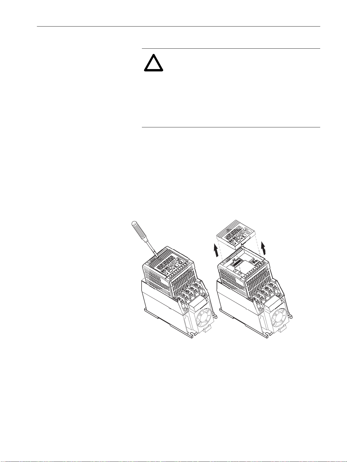
Keypad or Ready/Fault Panel Removal
Before install ing the PD1 Module, i t may be necessary to remove a
previously installed Program Keypad Module or Ready/Fault panel.
1. Verify that all power to the drive is removed.
2. Insert a small screwdriv er into slot, pry back and pivot module
out. Avoid bending or twisting the contact pins located under the
module.
Figure 3.2
Removing Program Keypad Module
Program Keypad Module
(or Ready/Fault Panel)
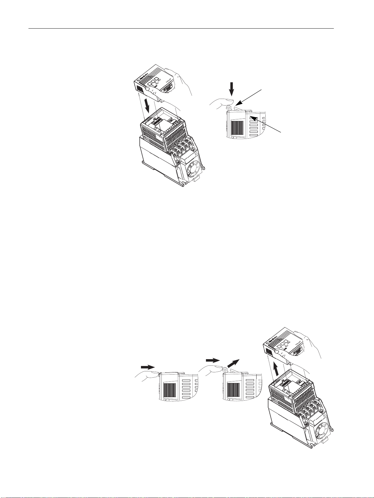
Installing the PD1 Module
After setting the rotary switches, install the PD1 Module in the drive
by following these steps:
1. Verify that all power to the drive is removed.
2. Verify that the latch is up (see Figure 3.3). Insert the modul e,
ensuring that the pins on the back of the module line up with the
drive connector/expansion port.
3. Press the module down until it is full y seated (side s are flush with
the top surface of the drive).
4. Pr ess t h e latc h down u ntil it s naps into place.
Page 14
3–4 Installation and Wiring
Figure 3.3
Communication Module Installation
Latch must be in this position before
installation. Once installed, push the
latch down until it locks into place.
Module should be flush
with top surface of drive
Removing the PD1 Module
If you need to reconfigure the PD1 Module rotary switches, you must
remove the module from the drive.
1. Verify that all power to the drive is removed. Review Attention
statement on page 3–3.
2. Disconnect the cable/connector from the module (if present).
3. Press in on the module’s latch and then push away and up.
4. Grasp the module and pull straight up. Avoid bending or twisting
the contact p ins loc at ed under neath the cen ter portion of the
module.
Figure 3.4
Removing the Communication Module
Page 15

Installation and Wiring 3–5
Wiring the Drive Terminal Block
The 160 drive and 160-PD1 interface can be controlled on a network
in 2 different mod es.
[Input Mode] = 2
This mode is used where the dr i ve is controlled sol ely by the netw ork.
The 160-SSC drive requires, that a stop signal is present on the
hardware terminals, before the drive can be started.
Control
ether a wire bridge or a normally closed stopping device.
Fitting a stopping device (e.g. pushbutton) in place of the link,
can provide addition al lo ca l st op/emergency stop capability.
Important: Failure to link the stop command input, will result in the
[Input Mode] = 6
This mode is used whereby it is possible to control the drive across
the network or locally, by putting a switch on the Contro l Terminal
Block 3 (TB-3) pins 7 & 8.
When the switch is closed, the Frequency source comes from the
reference as defined by P59 - [Frequency Select]. As we are using
the 160-PD1, the reference is across the Profibus network.
Additionally the start command is active across the network.
Terminal Block 3 (TB-3) pins 7 & 8 need to be linked by
drive generating a fault, and inability to run accross a
network.
When the switch is open, the Frequency source comes from the
terminal block (analogue reference or potmeter), regardless of the
setting of P59 - [ Freque nc y Sel ect]. Additiona ll y the star t command is
controlled by the terminal block or keypad.
Page 16
3–6 Installation and Wiring
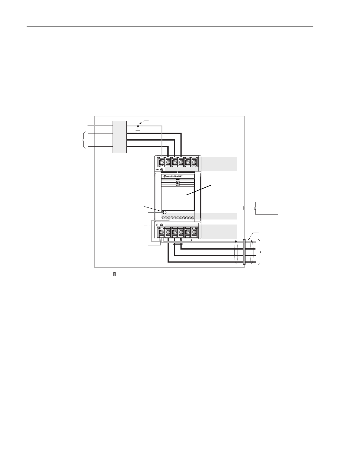
Wiring the PD1 Ground Terminal
AC
nput Line
PE
T (L3)
Line
S (L2)
Filter
R (L1)
Ground T erminal – PE
PD1 Ground Terminal
Ground T erminal – PE
In addition to the ground connections shown in Appendix C of the
160 SSC manual, the ground terminal at the bottom of the PD1
module must be solidly connected (and as short as possible) to the
output ground terminal at TB2 of the 160 SSC drive, as shown in
Figure 3.4:
2
This connection shall have a cross section of 1.5 mm
Figure 3.5
PD1 Module Grounding
Enclosure Ground Connection
T/L3
S/L2
R/L1
BR–
BR+
DC–
DC+
Line Power TB1
PD1 Communi cation
Module
to TB3
Control Wiring TB3
Motor Wiring TB2
S/L2
R/L1
T/L3
FAULT
READY
1
45678910112
3
V/T2
U/T1
W/T3
.
Control
Cabinet
➊
Shielded Motor Cable
Shielded Enclosure
= EMC Tested Shielded Cable Clamp (or Metal Conduit)
➊
When the control circuitry is located outside of the 160 enclosure.
W/T3
V/T2
U/T1
to Motor
Page 17
Installation and Wiring 3–7
Wiring the Connector
The examples below can be used as a guide when wiring.
Important: Keep communicatio n wiring awa y from high noise sources
such as mot o r cabl es . Use terminated cabl e on ly fo r th e
last node (end of chain)
Figure 3.6
Wiring the PD1 Connector
Ground Connection
Terminal
Pin 1
9-Pin, Female D-Shell Connector
Pin 9
The PDP network cables are connected to the PD1 module using a
9-pole D-Shell connector with a suitable opening facing downwards.
The pin layout of the connector follows the Profib us s tandard.
The Vcc (pin 6) and GND signal (pin 5) can be used for external bus
termination.
Important: Only use cable that c onforms to Pro fi Bus cable standards .
Belden type 3079A ProfiBus cable or equivalent is
recommended.
Figure 3.7
Cable Termination
RxD/TxD-N 8
RxD/TxD-P 3
Vcc 6
GND 5
A
B
390 220 390 Ohm
8 RxD/TxD-N
3 RxD/TxD-P
Termination resistors are only required at both ends of the network
Pin Name Function
Case Shield Bus cable shield. Connected to PE internally on the PD1
3 B-Line Positive
5 GND BUS Isolated GND
6 +5V BUS Isolated +5V Vcc*
8 A-Line Negative
Page 18

3–8 Installation and Wiring
Connecting the Communication Cable to the Module
Network
Termination
Resistor *
PLC
Profibus
Master
Follow these steps to connect your module.
1. Verify that the cable/connector i s corr e ctly wired (see Figure 3.6
and Figure 3.7).
2. Locate the D-shell connector at the base of the PD1 Module.
3. Plug cable/connector into the PD1 D-shell connector and secure.
Figure 3.8
Profibus Connection
Internal
Network
Termination
Resistor
Profibus-DP
SSC160-C
Profibus-DP
SSC160-C
Profibus-DP
SSC160-C
Profibus Network Termi nation
* Termination is required at both ends of the network.
The Profibus master might offer on-board termination.
Make sure that other Profib us slav es with on-board term ination are set
up correct l y.
The network must be terminated at the first (network master) and the
last PD1 module. A bus cable connector with an internal resistor
network must be used as no internal termination is provied on the
PD1 module. (Refer to Figure 3.7).
Page 19

Chapter
Modes of Operation
Chapter 4 contains the following information:
• Powering up the drive with the PD1 Module installed
• LED Indicators
• Operation Modes
4
Powering Up the Drive
LED Indicators
After you have installed the PD1 Module, apply power to the drive
and to th e connected d ev ice. The R EADY LED should illuminate.
If it does not, refer to Chapter 8, Troubleshooting.
The PD1 Module has three LEDs (see figure below) which provide
module status.
READY LED
FAU LT LED
COMM LED
The LEDs are defined as follows:
•COMM – The COMM LED has four possible states:
Green (steady) Communication ok, data is exchanged.
Red (steady) Diagnostics failed at power-up
or fatal error.
Red (flashing) Profibus configuration fault (5 to 6 flashes).
Off No communication takes place / No power
For more details refer to Troubleshooting, Table 8.A
•FAULT – This LED tracks the fault status of the 160 Drive.
When no faults are present, the LED will be off. The LED will
illuminate (red) if a drive or an option board fault occurs.
•READY – The Ready LED will illuminate (green) whenever the
module is connected to the drive and power is applied.
Page 20

4–2 Modes of Operation
Operation Modes
The PD1 Module has three modes of operation.
• Power-up mode
• Run mode
• Error mode
Power-up Mode
The following sequence of operation occurs:
1. During power-up, the READY LED illuminates green and the
FAULT and READY LED’s light up for a short periode.
2. The module reads and stores the rotary switch settings.
If the power-up sequence is successful, the module enters the run
mode and the COMM LED turns solid green as soon as data is
exchanged.
If the powe r -up sequ ence f ails, the COMM and FA ULT LED will stay
solid red and the module will enter the Error Mode (see below).
Run Mode
After a successful power-up, the PD1 Module enters the run mode
and operates as a slave device to a master d e v ice. In run mode, the
module:
• Accepts and responds to messages from the master on the
network.
• Monitors cable integrity an d t ransmissio n performance.
• COMM LED green if communication with the master is ok.
If an error is detected, the module enters Error Mode (see below).
Error Mode
Errors are indicated either by the COMM LED:
• Flashing red (5 to 6 flashs) signals a Profibus configuration fault
• Flashing red (other than 5 to 6 flashs) signals a fatal error
• Solid red signals that the power-up sequence failed
or the FAULT LED, which illuminates solid red at any 160 drive fault
or option board fault.
SSC160 drive faults are also indicated by the FAULT LED.
(See table 8.B).
Refer to Chapter 8 for details on how to recover from an error.
Page 21

160 S S C Dr ive Parameters
Chapter
5
Profibus Parameter Descriptions
and Data Protocol
This chapter provides a listing and description of the Bulletin 160
Drive parameters related to Network Operation, and the PD1 Module
Data Protocol information.
Important: Refer to your 160 S SC™ Variable Speed Dri v e (Ser ies C )
User Manual for drive parameter descriptions.
Drive PD1 (Tab. 5E)
46 4
5
59 4
5
66 4
5
Access [Parameter Name] and Description
Read
write
Read
Write
Read
Write
[Input Mode]
Configures the TB3 control inputs for various 3-wire or 2-wire control schemes.
Also enables/disables the program keypad module input control.
Settings: must be set to either
2 = Program Keypad Module control or
6 = 2-wire TB3 Control/Keypad or Communication control
A contact closure on TB3 terminals 7 and 8 is required for the drive to respond to a
Run command.
Important: This parameter cannot be program med while the drive is running.
In addition, power must be cycled or P56 - [Reset Function] must be
set to 2 for the change to take effect.
[Frequenc y Sele c t]
Selects the source of the frequency command for the drive.
The reference to P58 - [Internal Frequency] is bipolar, so a positive reference gives
forward rotation, and a negative reference gives reverse direction.
Settings:must be set to 1 = internal freq. command from P58 - [Internal Frequency].
[RPM Scaling]
A scaling factor is required to interpret a speed reference in RPM at the [Maximum
Frequency] of the dri ve . The 160 Drive parameter P66 - [Preset Frequency 5] is
used by the PB1 Module for this purpose.
P66 = rRPM / rf
rf: required motor frequency to achieve rRPM
rRPM: final RPM at application output (e.g. speed at gear box output),
which will be displayed at Profibus Master
Application Speed [rpm] = Drive Output Frequency x P66 [RPM Scaling]
e.g. 1500 rpm = 50 Hz x 30 (4 pole motor) P66 = 30.0 (300)
900 rpm = 60 Hz x 15 (8 pole motor) P66 = 15.0 (150)
Gear Box 1:20: 75 rpm = 50 Hz x 1.5 (4 pole motor) P66 = 1.5 (15)
For network operation the P66 values in brackets are valid, which are ten times the
values for keypad operation.
If P66 - [RPM Scaling] is set to 0, speed reference may be sent via the network
directly in 1/10 of Hz.
e.g. SpeedRef [Hz] (Profibus) = 405 results in 40.5 Hz of output frequency.
Speed feedback is considered to be P01 - [Output Frequency],
which reflects the output frequency considering ramp rates.
Min./Max.
Values DefaultParam. No Param. Oper.
0/9 0
0/1 0
0-240
[0-2400]
50
ATTENTION: Unpredictable motor speed can cause deat h,
injury or equipment damage. Do not use P66 as the [Preset
!
Frequency 5] function via control terminal wiring.
Page 22

5–2 Profibus Parameter Descriptions and Data Protocol
Drive PD1 (Tab. 5E)
Access [Parameter Name] and Description
116 4 Read only [PD1 SW Version]
This parameter indicates the software version of the PD1 option.
The number is in the form of xx.yy where xx indicates the major revision level and yy
indicates the minor revision level.
Min./Max.
Values DefaultParam. No Param. Oper.
0.00 to 10.0 1.0
Note: P57 [Program lock] may be set to 1 (locked), b ut parameter prog ra m m in g vi a network w ill st ill be
possible.
Profib us -DP Data Protocol
This chapter provides you with the PD1 Module Data Protocol
information.
Data from Profibus-DP Master to PD1 Slave
The Profibus Telegram consists of several bytes (words) according to
the follo wing table :
Table 5. A
Byte Byte No. Description
Control Word (LSB) 1 Control Word according to PROFIDRIVE and SSC160
Control Word (MSB) 2 Includes bits for parameter access control
(see table 5.E)
Speed Reference (LSB) 3 Speed reference in 0.1 Hz
Speed Reference (MSB) 4 0 to 2400 = 0 to 240 Hz
Parameter Value (LSB) 5 Parameter value
Parameter Value (MSB) 6
Par. Number 7 Parameter number to access (refer to SSC160 manual)
Reserved 8 not used
Data from PD1 Slave to Profibus-DP Master
Table 5. B
Byte Byte No. Description
Status Word (LSB) 1 Status Word according to PROFIDRIVE and SSC160
Status Word (MSB) 2 Includes bits for par ameter access control
(see table 5.E)
Speed Feedback (LSB) 3 Output Frequency
Speed Feedback (MSB) 4 Speed feedback corresponds to P01 [Ou tput
Frequency], w hich re flects the output frequency
considering ramp rates. (scaling as above)
Parameter Value (LSB) 5 Parameter value
Parameter Value (MSB) 6
Parameter Number 7 Parameter number to access (refer to SSC160 manual)
Parameter Access Status 8 Parameter Access Status=0x01 indicates a valid
access cycle (see table 5.G)
Page 23

Profibus Parameter Descriptions and Data Protocol 5–3
Control and Status Word PROFIDRIVE
Control an d St at u s w or d b its ar e defined as follo ws (speed control):
Table 5. C
Control Word (Bit definition)
Bit No. PROFIDR IVE (Control) Function
0 On / Off 1 1 = Enable op., 0 = Stop drive according to P34
1 Operating condition / Off 2 1 = Enable operation according to P34
2 Operating condition / Off 3 1 = Enable operation, 0 = Fast Stop
3 Enable / Inhibit operation 1 = Run / Start operation,
4 Operating Condition /
Inhibit ramp
5 Reserved
6 Enable / Inhibit Setpoint 1 = Speed Ref Enable
7 Acknowledge Fault Reset at 0 to 1 transition
8 to 12 Reserved
13 Parameter Operation 0
14 Parameter Operation 1 Parameter access according to Table 5.E
15 Parameter Operation 2
1 = Enable,
0 = Ramp to zero
To start the drive, set the control word (Low Byte) from 6 t o 5Fh.
To stop the drive, set the control word (Low Byte) to 57h.
T o c ont rol the dr i ve via Terminal Block (TB3), the Control Word Lo w
Byte must be set to 06h (state READY TO SWITCH ON).
Table 5. D
Status Word (Bit definition)
Bit No. PROFIDRIVE (Status) Function
0 Ready / Not for switch on 1 = Ready (Diagnostics o.k.)
1 Ready / Not for operation 1 = Ready (Diagnostics o.k.)
2 Operation enabled / inhibited 1 = Drive operating (Bit 3 of Control Word)
3 Fault / no Fault 1 = Faulted
4 No Off 2 / Off 2 1 = Enabled (Bit 1 of Control Word)
5 No Off 3 / Off 3 1 = Enabled (Bit 2 of Control Word)
6 Switch On Inhibit / not inhibit 1 = Inhibited (Bit 1,2 of Control Word not set)
7 Reserved
8 Ref. Within Limits / not 1 = Speed Reference within range (P32, P 33)
9 Control requested /
operation on site
10 Ref. reached 1 = Speed Reference reached
11 Direction 1 = Reverse, 0 = Forward
12 Reverse Request 1 = Reverse Request at TB input
13 Parameter Operation 0
14 Parameter Operation 1 Parameter access according to Table 5.E
15 Parameter Operation 2
1 = Master is requested to take control
* Internal speed reference/feedback is computed in 0.1Hz increments.
Due to rounding issues speeds in RPM may differ.
Resolution error in RPM = P66 * 0.05.
Example: for P66 = 16.6 the possible error is 1 RPM.
Page 24

5–4 Profibus Parameter Descriptions and Data Protocol
Stat e Transitio ns
RUNNING
0011' 0111 0011'0001
Control Words
Status Words
The following Figure 5.1 shows the most important state transitions
Figure 5.1
State Diagram
NOT READY TO
SWITCH ON
0FF2
or
0FF3
x1x1'1111
01xx'0000
xxxx'x110
READY TO
0FF1
(Low Byte) appear outside the boxes
(Low Byte) appear inside the boxes
SWITCH ON
Acknowledge Bit
1
—>
0
FAULT
0xxx'1000
Parameter Operation
Acco rdin g to Table 5.E, t hree p a rame ter op e r a tion bits in t he cont rol/
status word allow access t o certain p arameter values:
Table 5.E
Bit
Parameter Operation
0 0 0 0 No operation
1 0 0 1 Read Attr ibutes
2 0 1 0 Read minimum
3 0 1 1 Read maximum
4 1 0 0 Read value
5 1 0 1 Write value
6 1 1 0 Read default
7 111Unused
15 14 13 Description
Page 25

Profibus Parameter Descriptions and Data Protocol 5–5
P arameter Access
Parameter Attributes
Each parameter is described by an attribute to be read according to
table 5.F. The attribute consists of one word with 2 bytes which are
defined as follows:
High Byte stores the Unit (scaling) according to the table 5.G,
Low Byte stores the parameter number.
Table 5.F
High Byte Units
0 Decimal 1
1 Decimal 0.1
2 Decimal 0.01
3 Hexadecimal 1
4 Binary 1
5 Decimal (signed) 1
6 Decimal (signed) 0.1
7 Decimal (signed) 0.01
Parameter Access Status
The following access codes are returned i n t h e Parameter Access
Status Byte:
Table 5. G
Fault Code Fault Description Parameter Access Status
.
Bit 7Bit 6Bit 5Bit 0
- Network option is processing access
request
0 No fault, access successfull 0001
1 Parameter value is out of limits 0011
2 Parameter write attempt while drive is
running
3Parameter number is too small 0111
4 Parameter number is too high 1001
5Parameter number not valid 1011
6 No valid response from drive 1101
7Incorrect Parameter Operation code1111
xxx0
0101
A successful access is indicated by Access Status Byte 000’0001.
Page 26

5–6 Profibus Parameter Descriptions and Data Protocol
End of Chapter 5
Page 27

Chapter
6
Using the 160-PD1 on Profibus
The purpose of this chapter is to provide an example of the steps
necessary to use the 160-PD1 on a Profibus network. As Profibus is a
3rd party network, we will be using the SST-PFB-SLC scanner to act
as a master for Profibus, residing in an A-B SLC500 rack.
The SST scanner sends I/O messages periodically to a Bulletin
160-PD1 to start and stop the dri v e and co ntrol i ts spee d. Additio nally
the Bulletin 160-PD1 responds to these I/O message s b y sending
status messages and speed feedback back to the scanner. In this way
the ladder logic program in the A-B SLC500 PLC can control the
drive.
The Bulletin 160-PD1 a lso suppor ts a Prof ib us t ele gram which c an be
used to configure or read parameters from the drive .
This chapter contains the following information:
• How to create a Profibus network configuration frame.
Required Tools
• How to configure the SST-PFB-SLC scanner for use in a SLC
rack.
• A sample ladder logic program to control the Bulletin 160 SSC
using I/O messaging.
• A description of the Profibus te l egram.
• A sample ladder logic program to execute the telegram.
The SST-PFB-SLC scanner for the SLC500 is used in the examples
in this manual. However the concepts demonstrated in the examples
apply to any Profibus master.
The following too l s are needed to comp l et e this chapter.
• Bulletin 160 series C or higher, equipped with a 160-PD1
Profibus communication module
• SLC500 processor with a digital input card to issue start & stop
commands.
• SST-PFB-SLC scanner card, SST Configuration Tool and null
modem cable.
Page 28

6–2 Using the 160-PD1 on Profibus
Create a Profibus Network Configuration Frame
The SST Profibus scanners come with a software tool for configuring
the scanner. If you activate this program in your computer the
following screen should appear.
Network
Configuration
window
Device
Library
window
Installing the 160-PD1 GSD File in the Software Tool Library
Online
Browse
window
Follow the steps outlined below only when a new GSD file needs to
be added to the SST PROFIBUS Configuration Software Tool.
Typically this is only done once, after the software tool is initially
installed or before configuring the scanner for the network.
The software tool comes with standard data files. Additional data
files, such as the 160-PD1 GSD file, will need to be added to
configure the 160-PD1 in the scanner.
Click on the ”New Devic e” icon to add GSD files to the softw are
library tool.
An ”Add PROFIBUS devices” Applet window will appear.
Prompts for the location of the PROFIBUS data files to be added to
the library will follow.
Page 29

Using the 160-PD1 on Profibus 6–3
Find the dire ct o ry l o cation of the data file(s) you wish to add
(typically, the source location is a floppy disk in drive A: ).
”PD1_0587.gsd” is the GSD file for the 160-PD1 as shown below.
Select ”PD1_0587.gsd” for the 160-PD1 and click Open.
Click on the (+) sign of the Slaves folder as shown below.
The software tool will automatically create a Rockwell Automation
sub-folder (in the Slaves folder) if it does not already exist. The
160-PD1 is now shown in the library and the software tool is now
ready to configure a 160-PD1 on a PROFIBUS network.
Page 30

6–4 Using the 160-PD1 on Profibus
Configuring the SST-PFB-SLC Scanner
The following steps are performed to configure the SST-PFB-SLC
scanner using the SST PR OFIBUS configuration softw are tool.
Click on the (+) sign of the Masters folder in the Library window to
open the SST sub-folder. Ava ilable DP masters are displayed in this
sub-folder.
Then, double-click the SST-PFB-SLC MASTER in the Masters
folder in the Library window to add the scanner to the network.
A user-defined Name and Description can be given to t he scanner.
In our example the scanner will be Station 0 on the network.
The Paramet er tab i s n o t s h own here a s th e defa ult s ett i ngs are used.
Connection and Baud Rate settings configure how the software tool
will communicate with t h e CON FIG RS232 port on the scanner.
Click on the COM Port tab.
Accept the settings in our example (COM1 on the PC at 115200 bps
baud rate), as shown below.
When you click OK to accept these settings, the scanner will appear
in the Network window.
Page 31

Using the 160-PD1 on Profibus 6–5
Double-click on the scanner in the Network window.
Double-click on PROFIBUS_DP will open the Network window.
Specify the Baud Rate 1.5 M Baud and click OK to accept the setting.
Click on the (+) sign of the Slaves folder in the Library window and
the Rockwell Automation sub-folder to display the available DP
slaves or the 160-PD1 slave
Double-click on the 160-PD1 listed in the Device Library and the
Rockwell Automation library folder. A user-defined Name and
Description can be given to this 160-PD1.
In our example, this device will be Station 3 on the network. Other
stations may be chosen by using the arrow to display a drop-down list
in the Station window.
Page 32

6–6 Using the 160-PD1 on Profibus
Click OK and the GSD file previously loaded, creates a fixed format
I/O structure of 8 bytes in and 8 bytes out. Click on the Modules tab
to view.
Now the 160-PD1 address starting point needs to be specified.
Click on the SLC Address tab.
In our SLC example code, the 160-PD1 has been mapped at:
Inputs I:2.14
Outputs O:2.14
This is 14 words offset from the start address of the card.
Select the ” Out 8byt es” from the available options, and specify an
offset of 14.
Page 33

Using the 160-PD1 on Profibus 6–7
Select the ”In8bytes” f ro m the available options and specify an offset
of 14.
Now click OK to accept these addresses.
Use the null modem cable that came with the scanner to connect
COM1 on the PC and the CONFIG RS232 port on the scanner.
Downloading the configuaration to the scanner is protected by the
processor keyswitch. Turn the keyswitch to "Program".
Right-click on the scanner in the network window and select ”Load
Configuration”. If a minimum cycle time attention window pops up,
click OK to continue. After the configuration has been loaded into the
scanner ”Configured Program” will be displayed in the message
window. Turn the processor keyswitch to "Run".
Page 34

6–8 Using the 160-PD1 on Profibus
Click File and Save As from the tool bar, as an unique File Name.
The configuration of the scanner is now complete.
Note that cycl i ng power t o t he scanne r is recommended.
Summary of the Example Scanner Configuration
Table 6. A
Scanner to 160-PD1 Control words Byte SLC Add
Control Word (LSB) 1 O:2.14
Control Word (MSB) 2
Speed Feedback (LSB) 3 O:2.15
Speed Feedback (MSB) 4
Parameter Value (LSB) 5 O:2.16
Parameter Value (MSB) 6
Parameter Index 7 O:2.17 (LSB)
Parameter Handshake
8
O:2. 17 (MSB)
Table 6. B
160-PD1 to scanner Status words Byte SLC Add
Status Word (LSB) 1 I:2.14
Status Word (MSB) 2
Speed Feedback (LSB) 3 I:2.15
Speed Feedback (MSB) 4
Parameter Value (LSB) 5 I:2.16
Parameter Value (MSB) 6
Parameter Index 7 I:2.17 (LSB)
Parameter Handshake
8
I:2.1 7 (MSB)
Page 35

Using the 160-PD1 on Profibus 6–9
Setting up the SST-PFB-SLC Scanner Card to work in the SLC
In order t ha t the scanner can operate i n the SLC rack, first the SLC
rack configur ation needs to be set up. Using RSLogix500 in an offline
state, create a new program and setup the I/O configurat ion as sho wn.
The I/O configuration utilizes a digital input card in slot 1 to provide
com m ands to star t & stop the drive et c.
The SST-PFB-SLC scanner card i s d ropped into slo t 2 u s i ng ”O t her”
from the cards available column. You are require d t o specify the card
with an ID Code = 13635.
Please note tha t the ex ample c onf igura tion con tains a n addi tional card
in slot 3 which is not used in the following example.
With the card in slot 2 selected, click on Adv Config to specify the
number of words used in the card.
Page 36

6–10 Using the 160-PD1 on Profibus
Specify values as shown in the following window.
Click OK when finished and download the configuration to the SLC.
Page 37

Using the 160-PD1 on Profibus 6–11
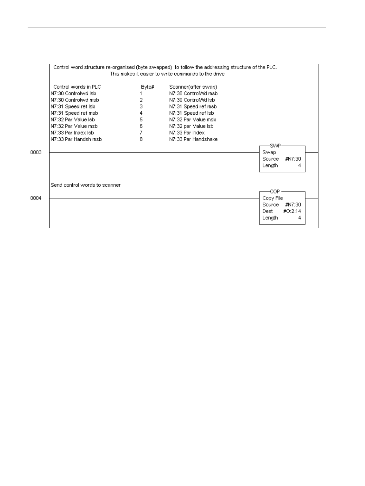
SLC Ladder Logic Example
Profib us scanners v ary from manufacturer to manuf acturer , in how the
bytes are or de re d i n a w o rd . T he SST-PFB-S LC s c ann er ca r d rec eives
/ transmit data with the Most Significant Byte (MSB) first and the
Least Significant Byte (LSB) second. This is opposite to ho w we read
/ write information in the SLC. This section of program below
reverses the high / low byte order using the SWP instruction.
Figure 6.1
SLC Ladder Logic Example.
SLC Ladder diagram continued on next page
Page 38
6–12 Using the 160-PD1 on Profibus
SLC Ladder Logic Example (continued)
Once the bytes have been swapped, the control and status words can
be manipulated as per normal.
Note: If your scanner does not order the MSB first, LSB second, but
the other way around, then the program above can be omitted.
Page 39

Using the 160-PD1 on Profibus 6–13
Controlling the Drive
Adjust the drive parameters as specified at the start of chapter 5
in order to test the drive with the following program example.
Figure 6.2
Drive Test Program Ladder Logic Example.
Ladder diagram continued on next page
Page 40

6–14 Using the 160-PD1 on Profibus
Drive Test Program Ladder Logic Example (continued)
Ladder diagram continued on next page
Page 41

Using the 160-PD1 on Profibus 6–15
Drive Test Program Ladder Logic Example (continued.
Page 42

6–16 Using the 160-PD1 on Profibus
The Profibus Telegram
The Profibus implementation of the 160-PD1 (as specified by the
GSD file) suppor ts 2 diff erent types of indepe ndent data tr ansmis sion.
The 2 words of control and status utilized above is the process data
cyclically transmitted / received, to start / stop the drive, provide a
reference, and get dr i v e feedb ack. This da ta trans mission pr ovide s th e
quickest means of communicating with the drive.
An additional parameter data channel is provided which is much
slower , w orking around the proc ess data cha nnels abov e, to r ead/write
parameters to a drive. This handles one parameter at a time, specified
by an index (parameter number) and a data channel.
In the example below, N7:41 contains the parameter number (Index),
and N7:4 2 contains a ny data that is to be written to the parameter
specified. These are copied to the Control words of the scanner for
action (N7:32 & 3). The command to read (80h) or write (A0h) is
copied from N7:43 & N7:44 and is shown on Rungs 4 & 5 on the
ladder above, as it forms the MSB part of the Logic Control Word.
This is an example of a read drive p arameter (all values in hex)
N7:40 is the Logic Control Word, where LSB = 5F (Drive running),
MSB = 80 (read operation).
N7:41 is the parameter number 2 = [Output Voltage].
N7:50 is the data from the drive on N7:22.
The value of D4h represents 212 Volts decimal.
N7:51 is a copy of the parameter number (Index) in the LSB
and the handshake if read operation was successful (MSB = 1).
This is another example of a read drive parameter
(all values in hex)
N7:40 is the Logic Control Word, where LSB = 5F (Drive running),
MSB = 80 (read operation).
N7:41 is the parameter number 8 = [Heatsink Temperature].
N7:50 is the data from the drive on N7:22.
The value of 45h represents 69 degrees C decimal.
N7:51 is a copy of the parameter number (Index) in the LSB
and the handshake if read operation was successful (MSB = 1).
Page 43

Using the 160-PD1 on Profibus 6–17
This is an example of a write drive parameter (all values in hex)
N7:40 is the Logic Control Word, where LSB = 5F (Drive running),
MSB = A0 (write operation).
N7:41 is the parameter number 1Eh (30 decimal) = [Accel Time 1].
N7:42 is the data to be sent to the drive 14h (20 decimal),
which represents an Accel = 2.0 seconds.
N7:50 is not relevant when a write operation i s i n progress.
However it will provide 14h when revert to a read operation.
N7:51 is a copy of the parameter number (Index) in the LSB
and the handshake if read operation was successful (MSB = 1).
This i s an exampl e of a read after a write drive parameter
(all values in hex)
Page 44

6–18 Using the 160-PD1 on Profibus
Figure 6.3
Profibus T elegram Ladder Logic Example.
Page 45

Chapter
Controlling the Drive
Controlling the 160 Drive from a programmable controller is
accomplished using the Telegram described in Chapter 5 to
communicate through the PD1 Module to the drive.
7
Setting the Drive to Enab le Network Control
The 160 driv e must be configured to accept logic and speed
commands from the network. This can be done by configurin g two of
the 160 parameters:
1. Set P46 - [Input Mode] to a value of “2” or “6” as described in the
following Table. This will configure the drive to accept the logic
commands from the network.
Important: The d rive may be ope r a ted i n other mo des as long as
the Profib us Master provides an Enable command
(control w o rd = 0x6)
2. Set P59 - [Frequency Select] to “1.” This will configure the drive
to accept speed commands fro m the network .
3. Set P66 - [RPM Scaling] according to rated namepla te s peed.
Changing the above parameters can be done with the 160 Keypad
Module or configuration software such as DriveExplorer.
Important: For a new Input Mode to take af fect, dr i ve pow er must be
cycl ed o r para mete r P56 - [Reset Functions] must be set to
“2” instead.
Setting the Node Address
The node address on the PD1 Module should be configured to the
desired setting for the network. After configuration, install the PD1
Module into the 160 Drive as explained in Chapter 3.
Page 46

7–2 Controlling the Drive
End of Chapter 7
Page 47

Chapter
Troubleshooting
The purpose of this chapter is to help you troubleshoot your P D1
Module.
ATTENTION: Servicing energized industrial control
equipment can be hazardous. Electrical shock, burns, or
!
unin tent ional a c tuation o f controlled industrial equ ipment
may cause death or serious injury . Follow th e safety-rel ated
practices of NPFA 70E, Electrical Safety for Employee
Workplaces, when working on or near energiz ed equipment.
Do not work alone on energized equipment.
ATTENTION: Do not attempt to defeat or override fault
circuits. T he cause of a fault indicati on must be determined
!
and corrected before attempting operation. Failure to
correct a dri ve or system malfunct ion may result in personal
injury and/or equipment damage due to uncontrolled
machine system operation.
8
Setup
LED Indicators and Troubleshooting
Make sure parameters P46, P59, P66 and P116 have been set
according to chapter 5.
The PD1 Status LEDs can help you troubleshoot the module in the
event that problems occur. Refer to t he paragraphs that follow for
details.
Status LEDs
READY LED
The green READY LED will illuminat e whene ver the PD1 Module is
connected t o the drive and power is applied.
Page 48

8–2 Troubleshooting
COMM LED
The COMM LED provides status information on module operations.
Table 8.A shows how to use the LED to detect and correct common
operating problems.
Table 8. A
COMM LED Indications
Color State What It Means: What To Do:
Green Off No communication takes place,
No power.
steady Communication ok,
data is exchanged
Red steady Diagnostics failed at power-up
or Fatal Error
flashing A cascade of 5 or 6 flashs means
Profibus configuration fault.
Any other flashs indicate Fatal Error
Check Po wer Supply,
Network Configuration
No action required.
Cycle power to the drive. If problem
persists, exchange PD1 Module
Check Network Configuration,
Profibus Master Setup and
SSC160 Setting (Section 5)
Exchange PD1 Module
FAULT LED
When the FAULT LED lights red, a drive fault (including
Fatal Er r o r
or an option board fault is present. Drive fault codes can be read by
accessing drive parameter P07 - [L a s t Fau l t].
Refer to Tables 8.B and 8.C for fault descriptions/actions.
Table 8. B
160 Drive
Fault Code Fault Indication Description Corrective Action
00 No Fault The drive is currently not faulted. No action required.
03 Power Loss F ault DC Bus voltage remains below 85% nominal on
power up for longer than 5 seconds.
04 Undervoltage Fault DC Bus voltage fell below the minimum value
while the motor was running.
05 O vervoltage Fault DC Bus maximum voltage exceeded. Bus overvoltage caused by motor regeneration.
06 Motor Stall Fault Motor has stalled. Motor load is excessive. Longer accel time or reduced load required.
07 Motor Overload Fault Internal electronic overload trip. Excessive
motor load exists.
08 Overtemperature Fault Excessive heat detected. Clear blocked or dirty heat sink fins. Check ambient
11 Operator Fault The keypad has been removed while the drive
is powered.
12 Overcurrent Fault Overcurrent detected in hardware trip circuit. Check short circuit at the drive output or excessive
20 Drive Overload Fault An internal electronic overload trip has
occurred. The drive is overheating.
22 Drive Reset Stop input not present. Check stop input at TB3 terminal 8.
32 EPROM Fault EPROM has invalid data. Reset EPROM using P56 - [Reset Func tions].
33 Max Retries Fault Drive did not reset fault within the max retries
specified.
38 Phase U Fault Phase to ground fault detected between drive
and motor phase U.
1
1
Fault Codes
Monitor incoming AC line for low voltage or line power
interruption.
Monitor incoming AC line for low voltage or line power
interruption.
Extend the decel time, or install dynamic brake option
or external capacitor module.
Reduce motor load.
temperature. Check for blocked or non-operating fan.
Clear the fault. Do not remove the keypad
underpower.
load conditions at the motor.
Clear blocked or dirt y heat sink fins. Check ambient
temperature. Check for blocked or non-operating fan.
Repair system fault.
Check wiring between drive and motor. Check motor
for grounded phase.
Refer to the 160 SSC™ Variable Speed Drive (Series C) User Manual for the most cur rent faul t code
information.
),
Page 49

Troubleshooting 8–3
Table 8.B (continued)
160 Drive
Fault Code Fault Indication Description Corrective Action
39 Phase V Fault Phase to ground fault detected between drive
and motor phase V.
40 Phase W Fault Phase to ground fault detected between drive
and motor phase W.
41 UV Short Fault Excessive current has been detected between
these two drive output terminals.
42 UW Short Fault Excessive current has been detected between
these two drive output terminals.
43 VW Short F ault Excessive current has been detected between
these two drive output terminals.
48 Reprogramming Fault Occurs when reset defaults is performed. Clear fault.
49 Zero Overload Fault Occurs when load requires excessive current at
zero hertz.
1
1
Fault Codes
Check wiring between drive and motor.
Check motor for grounded phase.
Check wiring between drive and motor.
Check motor for grounded phase.
Check the motor and external wiring to the drive
output terminals for a shorted condition.
Check the motor and external wiring to the drive
output terminals for a shorted condition.
Check the motor and external wiring to the drive
output terminals for a shorted condition.
Reduce motor load and/or motor dwell time at zero
hertz.
Refer to the 160 SSC™ Variable Speed Drive (Series C) User Manual for the most cur rent faul t code
information.
Table 8. C
Network Fault Codes
Fault Code Fault Indication Description Corrective Action
51 Serial Fault No serial Connection established Check if SSC160 of version ‘C’ or higher has been
52 Network lost connection Timeout on Network Check connection between Master and Slave
53 False Drive Type Drive Type is not compatible to option board Check if SSC160 of version > ‘C’ has been installed.
installed. (Refer to drives nameplate)
Check 30 pin connector on the options back.
Check parameter setting according to Section 5.
Page 50

8–4 Troubleshooting
End of Chapter 8
Page 51

Specifications
Appendix
A
Electrical
Environmental
Communications
Mechanical
Supply Voltage Supplied by Drive
Power Cons u m ptio n 0.75 Watt s (150 m A ) maximum
Ambient Temperature
Operating 0 to 65° C (32 to 149° F)
Storage –40 to 85° C (–40 to 185° F)
Relative Humidity 0 to 95% non-condensing
Vibrati on 1.0 G Opera tional
2.0 G Non-operational
Shock 15.0 G Oper a tional
30.0 G Non-operational
Altitude 1,000 m (3,300 ft.) without derating
Baud Rate 9.6k - 12M BPS
Protocol PROFIDRIVE
Dimensions are in Millimeters and (inches)
(1)
17.34
(0.68)
(2)
21.4
(0.85)
(1)
Required for module removal.
(2)
Module adds this dimension to the overall drive depth.
Page 52

A–2 Specifications
End of Appendix A
Page 53

Index
B
Baud Rate
, 6–5, A–1
C
Cable Termination
Cabling
CE Complian ce
Communication Cable
Configuration
Control W o rd
Controlling, Drive
, 3–7
Profibus-DP
Rotary Switch
SST-PFB-SLC
, 3–7
, 3–1
, 3–2
, 3–2
, 6–4
, 5–3
, 6–13, 7–1
D
Data Protocol
Dimensions
, 5–2
, A–1
E
Error Mode
, 4–2
F
Fault Codes
, 8–2
Drive
Network
, 8–3
, 3–8
M
Manuals, related
Modes of Operation
Error Mode
Power-up
Run Mode
Module Installation
, p–ii
, 4–1
, 4–2
, 4–2
, 4–2
, 3–3
N
Node Address, Setting
P
Parameter
Access
attributes
Descriptions
Power-up Mode
Profibus
Telegram
Profibus Net work
Configuration Frame
Termination
Publications
On-Line
Related
, 5–5
, 5–5
, 5–1
, 4–2
, 5–2, 6–16
, 3–8
, p–ii
, p–ii
Q
, 3–2
, 6–2
G
GSD file
, 3–2, 6–2
I
Installation
, 3–1
K
Keypad Removal
, 3–3
L
Ladder Logic Example
Profibus Telegram
, 6–11
SLC
Test Program
LEDs
COMM
FAULT
READY
, 6–13
, 4–1, 8–2
, 4–1, 8–2
, 4–1, 8–1
, 6–18
Quick Start
, 2–1
R
Removal, Module
Required Tools
Run Mode
, 2–1, 6–1
, 4–2
S
Scanner
Configuration
Setting up
SST-PFB-SLC
Specifications
Communications
Electrical
Environmental
Mechanical
Status Wo rd
, 6–9
, A–1
, A–1
, 5–3
, 3–4
, 6–8
, 6–1
, A–1
, A–1
Page 54

Index–2
T
Troubleshooting
W
Web Sites
Wiring
, p–ii, 3–2
Drive Terminal Block
Ground Terminal
PD1 Connector
, 8–1
, 3–5
, 3–6
, 3–7
Page 55

Page 56

Publication 160PD1-UM011B-EN – June, 2003 P/N 899.02.86
Copyright © 2003 Rockwell Automation. All rights reserved. Printed in Switzerland.
 Loading...