

Page 1

160-IB1
InterBus
Communication
Module
Catalog Number: 160-IB1
Firmware: 1.00
User Manual
Page 2
Important User Information
Solid state equipment has operat ional char acteris tics differing from those of
electromechanical equipment. “Safety Guidelines for the Application,
Installation and Maintenance of Solid State Contr ols” ( Publication SGI-1.1)
describes some important differences between solid state equipment and
hard-wired electromechanical devices. Because of this difference, and also
because of the wide variety of uses for solid state equipment, all persons
responsible for applying this equipment must satisfy themselves t hat each
intended application of this equipment is acceptable.
In no event will Rock well Automation be responsible or lia ble for indirect
or consequential damages resulting from the use or application of this
equipment.
The examples and diagrams in this manual are included solely for
illustrative purposes. Because of the many variables and requirements
associated with any particular installation, Rockwell Automation cannot
assume responsibility or liability for actual use based on the examples and
diagrams.
No patent liability is ass umed by Rockwell Automation with respect to use
of information, circuits, equipment, or software described in this manual.
Reproduction of the contents of this manual, in whole or in part, without
written permission of Rockwell Automation is prohibited.
Throughout this manual we use notes to make you aware of safety
considerations.
ATTENTION: Identifies information about practices or
circumstances that can lead to personal injury or death,
!
property damage, or economic loss.
Attentions help you:
• identify a hazard
• avoid the hazard
• recognize the consequences
Important:
Identifies information that is especially important for successful
application and understanding of the product.
Shock Hazard labels may be located on or inside the dri v e
to alert people that dangerous voltage may be present.
MicroLogix and SLC are trademarks of Rockwell Automation.
PLC and PLC-5 are registered trademarks of Rockwell Automation.
RSLinx and RSLogix 500 are trademarks of Rockwell Software, Inc.
Windows and Windows NT are registered trademarks of Microsoft Corporation
InterBus is a registered trademark of the Interbus Club
DRIVECOM is a registered trademark of the DRIVECOM user organization
Page 3

Using This Manual
Product Overview
Quick Start for Experi enced
Users
Ins tallation and Wiring
Table of Contents
Preface
Who Should Use This Manual? . . . . . . . . . . . . . . . . . . . . . . . . . . . . . . . . . p-i
Conventions . . . . . . . . . . . . . . . . . . . . . . . . . . . . . . . . . . . . . . . . . . . . . . . . p-i
IB1 Compatibility. . . . . . . . . . . . . . . . . . . . . . . . . . . . . . . . . . . . . . . . . . . . . p-i
Reference Manuals. . . . . . . . . . . . . . . . . . . . . . . . . . . . . . . . . . . . . . . . . . p-ii
Safety Precautions . . . . . . . . . . . . . . . . . . . . . . . . . . . . . . . . . . . . . . . . . . p-ii
Chapter 1
Module Description. . . . . . . . . . . . . . . . . . . . . . . . . . . . . . . . . . . . . . . . . . 1-1
Chapter 2
Required Tools and Equipment. . . . . . . . . . . . . . . . . . . . . . . . . . . . . . . . . 2-1
Procedures . . . . . . . . . . . . . . . . . . . . . . . . . . . . . . . . . . . . . . . . . . . . . . . . 2-2
Chapter 3
DRIVECOM 20 Compliance . . . . . . . . . . . . . . . . . . . . . . . . . . . . . . . . . . . 3-1
EMC Directive 89/336/EEC Compliance. . . . . . . . . . . . . . . . . . . . . . . . . . 3-1
Low Voltage Directive 73/23/EEC Compliance. . . . . . . . . . . . . . . . . . . . . 3-1
Module Installation/Removal. . . . . . . . . . . . . . . . . . . . . . . . . . . . . . . . . . . 3-2
Keypad or Ready/Fault Panel Removal . . . . . . . . . . . . . . . . . . . . . . . . . 3-2
Installing the IB1 Module . . . . . . . . . . . . . . . . . . . . . . . . . . . . . . . . . . . . 3-2
Removing the IB1 Module . . . . . . . . . . . . . . . . . . . . . . . . . . . . . . . . . . .3-3
Wiring the Drive Terminal Block . . . . . . . . . . . . . . . . . . . . . . . . . . . . . . . . 3-4
Wiring the IB1 Ground Terminal . . . . . . . . . . . . . . . . . . . . . . . . . . . . . . . . 3-5
Wiring the Connectors . . . . . . . . . . . . . . . . . . . . . . . . . . . . . . . . . . . . . . . 3-6
Connecting the Communication Cable to the Module. . . . . . . . . . . . . . . . 3-7
Modes of Operation
InterBus Parameter
Descriptions and Data Protocol
Chapter 4
Powering Up the Drive . . . . . . . . . . . . . . . . . . . . . . . . . . . . . . . . . . . . . . . 4-1
LED Indicators . . . . . . . . . . . . . . . . . . . . . . . . . . . . . . . . . . . . . . . . . . . . . 4-1
Operation Modes . . . . . . . . . . . . . . . . . . . . . . . . . . . . . . . . . . . . . . . . . . . 4-2
Power-up Mode . . . . . . . . . . . . . . . . . . . . . . . . . . . . . . . . . . . . . . . . . . . 4-2
Run Mode . . . . . . . . . . . . . . . . . . . . . . . . . . . . . . . . . . . . . . . . . . . . . . . 4-2
Error Mode . . . . . . . . . . . . . . . . . . . . . . . . . . . . . . . . . . . . . . . . . . . . . . . 4-2
Chapter 5
160 SSC Drive Parameters. . . . . . . . . . . . . . . . . . . . . . . . . . . . . . . . . . . . 5-1
Data Channels . . . . . . . . . . . . . . . . . . . . . . . . . . . . . . . . . . . . . . . . . . . . . 5-2
Data from InterBus Master to IB1 Slave . . . . . . . . . . . . . . . . . . . . . . . . . . 5-2
Data from IB1 Slave to InterBus Master . . . . . . . . . . . . . . . . . . . . . . . . . . 5-3
Control and Status Word DRIVECOM 20/21 . . . . . . . . . . . . . . . . . . . . . . 5-3
Drive State Transitions . . . . . . . . . . . . . . . . . . . . . . . . . . . . . . . . . . . . . . . 5-4
Parameter Access. . . . . . . . . . . . . . . . . . . . . . . . . . . . . . . . . . . . . . . . . . . 5-5
Parameter attributes . . . . . . . . . . . . . . . . . . . . . . . . . . . . . . . . . . . . . . . 5-5
Parameter Access Fault Codes . . . . . . . . . . . . . . . . . . . . . . . . . . . . . . . 5-5
Communication Statistics . . . . . . . . . . . . . . . . . . . . . . . . . . . . . . . . . . . . . 5-6
Page 4

ii Table of Contents
Using the 160-IB1 on InterBus
Controlling the Drive
Troubleshooting
Specifications
Chapter 6
Required Tools. . . . . . . . . . . . . . . . . . . . . . . . . . . . . . . . . . . . . . . . . . . . . . 6-1
Create an InterBus Network Configuration Frame. . . . . . . . . . . . . . . . . . . 6-2
Controlling the Drive with I/O Messaging. . . . . . . . . . . . . . . . . . . . . . . . . . 6-6
The InterBus PCP Telegram. . . . . . . . . . . . . . . . . . . . . . . . . . . . . . . . . . . . 6-8
Reading and Configuring Parameters with the PCP Telegram. . . . . . . . . 6-11
Chapter 7
Setting the Drive to Enable Network Control . . . . . . . . . . . . . . . . . . . . . . . 7-1
Chapter 8
Setup . . . . . . . . . . . . . . . . . . . . . . . . . . . . . . . . . . . . . . . . . . . . . . . . . . . . . 8-1
LED Indicators and Troubleshooting . . . . . . . . . . . . . . . . . . . . . . . . . . . . . 8-1
Communication Status LEDs . . . . . . . . . . . . . . . . . . . . . . . . . . . . . . . . 8-2
FLT LED . . . . . . . . . . . . . . . . . . . . . . . . . . . . . . . . . . . . . . . . . . . . . . . . 8-2
IB1 Network Error Codes. . . . . . . . . . . . . . . . . . . . . . . . . . . . . . . . . . . . . . 8-4
Appendix A
Electrical . . . . . . . . . . . . . . . . . . . . . . . . . . . . . . . . . . . . . . . . . . . . . . . . . A-1
Environmental . . . . . . . . . . . . . . . . . . . . . . . . . . . . . . . . . . . . . . . . . . . . . A-1
Communications . . . . . . . . . . . . . . . . . . . . . . . . . . . . . . . . . . . . . . . . . . . A-1
Mechanical. . . . . . . . . . . . . . . . . . . . . . . . . . . . . . . . . . . . . . . . . . . . . . . . A-1
Index
Page 5

Preface
Using This Manual
The purpose of this manual is to provide you with the necessary
information to apply the Bulletin 160-IB1 Communications Module .
Described in this manual are methods for installing, configuring, and
troubleshooti ng t he 160-IB1 Inter Bus Communications Module.
For information on specific drive features, refer to the 160 SSC™
Variable Speed Drive (Series C) User Manual.
Important: Read this manual in its entirety before installing,
operating, servicing, or initializing the IB1 Module.
Who Should Use This Manual?
Conventions
IB1 Comp atibility
This manual is intended f or qua lif ied pe rsonnel. To make eff icient use
of the Communication Module, you must be able to program and
operate InterBus communications devices, as well as have an
understan d ing of the paramete r settings and functions of the 160
Drive.
In this manual we refer to the:
• 160-IB1 Communication Module as Communication Module ,
IB1 Module or Module.
• 160 SSC Adjustable Fr equency AC Drive as the 160 Drive or
drive .
In addition, parameter numbers and names (both 160 Drive and IB1
Module) are shown in bold typeface and follow the format PXX - [ *]
where P denotes parameter, XX denotes the two digit parameter
number, and * represents the parameter name.
For example, P01 - [Output Frequency].
The IB1 Module is compatible only with 160 Drives Series C or
above. When properly connected, the module communicates via an
InterBus networ k.
Page 6

p–ii Preface
Reference Manuals
For Read This Document
Additional information about networking and the SLC™ 500 SLC 500 Modular Hardware Style Manual 1747-6.2
Information about the AIC+ AIC+ Advanced Interface Converter User Manual 1761-6.4
Instruction set information for the SLC 500 and MicroLogix™
1000
For general MicroLogix 1000 information MicroLogix 1000 User Manual 1761-6.3
For 160 SSC Drive Information 160 SSC™ Variable Speed Drive (Series C) User Manual 0160-5.17ML
A complete listing of current Allen-Bradley documentation,
including ordering instructions. Also indicates whether the
documents are available on CD-ROM or in multi-languages.
A glossary of industrial automation terms and abbreviations Allen-Bradley Industrial Automation Glossary AG-7.1
Information about the SSC-IBS-SLC™ Scanner Scanner Card User Manual. SST Woodhead documentation can
The following documents contain addition al in f ormation c onc erning
Allen-Br ad ley p r oduc t s. To obtain a copy, contac t your loca l A l l e n -
Bradley Sales Office or visit the “On-Line Publications” area of the
Allen-Bradle y Internet home pag e at: www.ab.com.manuals
Publication
Number
SLC 500 and MicroLogix 1000 Instruction Set Reference Manual 1747-6.15
Allen-Bradley Publication Index SD499
Version 1.0
be obtained online at http://www.mySST.com/download/
Safet y Precau ti o n s
ATTENTION: Only personnel familiar with 160 Drives,
Communication Modules and associated machinery should
!
plan or implement the installation, start-up, configuration
and subsequent maintenance of this module. Failure to
comply may result in personal injury and/or equipment
damage.
ATTENTION: This module contains ESD (Electrostatic
Discharge) sensitive parts and assemblies. Static control
!
precautions ar e required when insta lling, testi ng, servicing,
or repairing this ass embly. Component damage may result
if ESD control procedures are not fol lowed. If you are not
familiar with static control procedures, reference
Allen-Bradley Publication 8000-4.5.2, Guarding Against
Electrostatic Damage or any other applicable ESD
protection handbook.
ATTENTION: The dri ve contains high v oltage capacitor s
which take time to di scharge after remov al of AC line po wer.
!
Before instal ling or removing the Communication Module,
ensure isolation of mains supply from line inputs R, S, T
(L1, L2, L3). W ait the r ecommended amount of ti me for the
capacitors to discharge to safe voltage levels (refer to the
160 SSC™ Variable Speed Drive (Series C) User Manual
for recommended time). Failure to do so may result in
personal injury or death.
ATTENTION: When a system is configured for t he first
time, the motor must be disconnected from the machine or
!
process during initia l system testing. Hazard of injury or
equipment damage may occur due to unint ended or
incorrect m achi n e mo tion .
Page 7
Product Overview
This chapter contains the following information:
• The physical layout of the module.
• Overview and components.
Chapter
1
Module Description
The IB1 Module is an optional interface device designed to provide a
direct, digital l ink between a n InterBus M aster and the 1 60 Dri v e. The
module connects to the drive through the expansion/keypad port on
the front of the drive. Refer to the Figure 1.1 for general layout of the
module and Chapters 4 or 8 for details on the LED indicators.
The IB1 Module has the following characteristics:
• 3 word pr ocess data chann el (control, r e f e r ence & diagnostics)
• 1 InterBus PCP telegram for configuration and reading of drive
parameters and error codes
• DRIVECOM 20 (part of 21) profile supp ort.
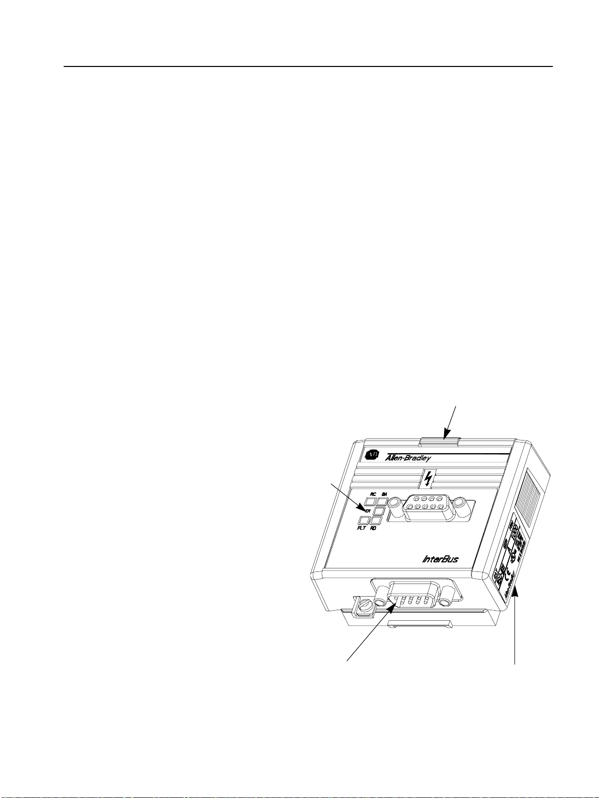
Figure 1.1
Module Front View
Module Installation Latch
Status LEDs
Refer to Chapt ers 4 & 8
for Further Information
9 Pin, Male D-Shell Connector
Refer to Chapter 3 for Details
Nameplate
Provides Firmware Version
and Series Letter
Page 8

1–2 Product Overview
End of Chapter 1
Page 9

Chapter
2
Quick Start for Ex perie nced Users
This chapter can help you start using the IB1 Communication
Module. If you have installed or configured a network previously and
are familiar with Allen-Bradley communication modules and drives,
this info r mati on can he lp re d u ce the time o f installation . I f you are
uncertain, use the full installation/configuration information
beginning in Chapter 3.
We base the procedures here on the assumption that you understand
the basic concepts, know how to program the 160 Drive and
understand electronic process control.
Because it is a start-up guide for experienced users, this chapter does
not contain detailed explanations about the procedures listed. It does,
however, reference other chapters in this book where you can find
more information.
If you have any questions or are unfamiliar with the terms used or
concepts presented in the procedural steps, always read the
referenced chapters and other recommen d ed documen ta t ion before
trying to apply the information.
Required Tools and Equipment
This chapter contains the following information:
• What tools and equipment you need.
• How to install and wire the Communicati on Module .
• System power-up procedures.
Have the f ollowing tools and equipment r eady:
• 3.2 mm (1/8 in.) flat blade screwdriver.
Page 10

2–2 Quick Start for Experienced Users
Procedures
Step Action
For Further Info rmation
1. Review Attention statements in the Preface.
Ensure that power to the 160 Drive has been removed. 160 Drive
2.
Verify that the 160 Drive is correctly installed and
3.
wired. Stop Input (TB3-7, TB3-8) must be jumpered
together to start drive.
Configure the 160 Drive for the IB1 Module so the drive
4.
can accept control logic and speed reference via the
network. *
Set P46 - [Input Mode] to a value of “2” or “6” as described
in Table 6.A. This will configure the d rive to accept the logic
commands from the network.
Note: If the value has to be changed, set P56 - [Reset
Functions] to “2” or reboot the drive.
Set P59 - [Frequency Select] to “1.” This will configure the
drive to accept speed commands from the network.
Set P66 - [RPM Scaling] for the RPM/Hz Scaling factor.
This allows theNetwork Reference to be in RPM.
Remove Program Keypad Module or Ready/Fault
5.
Indicati ng Panel fr om the dri v e.*
6. Install the IB1 Module.
7. Connect communication cable.
8. Power up the drive and the network.
9. Check for proper operation.
* Parameter setting might also be done via the
Keypad Module prior to removal
Refer to…
User Manual
160 Drive
User Manual
Chapter 5
(Parameters)
Chapter 3
(Installation)
Chapter 3
(Installation)
Chapter 3
(Installation)
Chapter 3
(Installation)
Page 11

Chapter
3
Installation and Wiring
This chapter contains inf ormation needed to:
• Check for rotational direction to comply with DRIVECOM 20.
• Meet the requirements of the EMC and Low Voltage direc tives
for CE compliance.
• Remove a pre-installed Program Keypad Module or Ready/Fault
Indicating Panel.
• Install the IB1 Module.
• Wire the communication cables.
• Wire the protection earth connection
• Remove the IB1 Module from the drive.
Read this chapter completely before you attempt to install or
configure your module. Before applying power, revie w the Attention
statements presented throughout this m anual. Verify that all
connections are secure and that all selections are correct.
DRIVECOM 20 Compliance
EMC Directive 89/336/EEC Compliance
Low Voltage Directive 73/23/ EEC Compliance
In order to comply with DRIVECOM 20 forward rotational direction
is def ine d as t urning cloc kwise facing motor shaft with positive speed
reference applied. Refer to the 160 SSC™ (Series C) Variable Speed
Drive User Manual, Start-up procedure, chapter 4.
ATTENTION: Unpredictable operation may occur if you
fail to chec k connections for compatibility with your
!
application. Unpre dictable operation may result i n personal
injury, death, and equipment damage.
This product complies with Ele ctromagnetic Compatibility (EMC)
Directive 89/336/EEC when conforming with the following
installation requirements:
• The essential requi rements for a confor ming EMC inst alla tion for
the Bulletin 160 SSC are employed. Refer to the 160 SSC™
Variable Speed Drive (Series C) User Manual.
This produc t complies with Low Voltag e Di rective 73/23/EEC when
conforming with the following installation requirements:
• The essential requirements for a conforming Low Voltage
Directive installation for the Bulletin 160 SSC are employed.
Refer to the 160 SSC™ Variable Speed Drive User Manual.
• Review the Attention st at ements in t h e P reface, and o t her areas
throughout this manual prior to installatio n o f the module.
Page 12
3–2 Installation and Wiring
Module Installation /Re moval
ATTENTION: The dri ve contains high v oltage capacitor s
which take tim e to discharge after remov al of mains supply .
!
Before installing or removing a keypad/module, ensure
isolation of mains supp ly from line inputs R, S, T (L1, L2,
L3). Wait the recommended amount of time for the
capacitors to discharge to safe voltage levels (refer to the
160 SSC™ Variable Speed Drive (Series C) User Manual
for recommended time). Failure to do so may result in
personal injury or death.
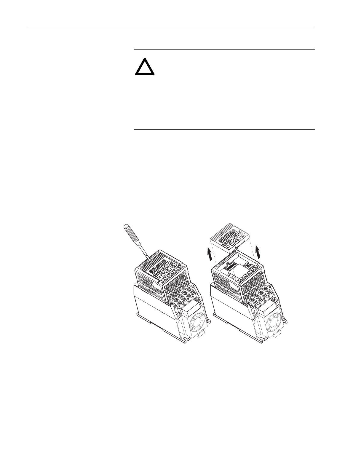
Keypad or Ready/Fault Panel Removal
Before installing the IB1 Module, it may be necessary to remove a
previously installed Program Keypad Module or Ready/Fault panel.
1. Verify that all power to the drive is removed.
2. Insert a small screwdriver into slot, pry back and pivot module
out. Avoid bending or twisting the contact pins located under the
module.
Figure 3.1
Removing Program Keypad Module
Program Keypad Module
(or Ready/Fault Panel)
Installing the IB1 Module
Install the IB1 Module in the drive by following these steps:
1. Verify that all power to the drive is removed.
2. Verify that the latch is up (see Figure 3.2). Insert th e m odule,
ensuring that the pins on the back of the module line up with the
drive connector/expansion port.
3. Pr ess the module do wn unti l it is full y seated (side s are flush with
the top surface of the drive).
4. Press t he latc h down until it sna ps into pl ace.
Page 13
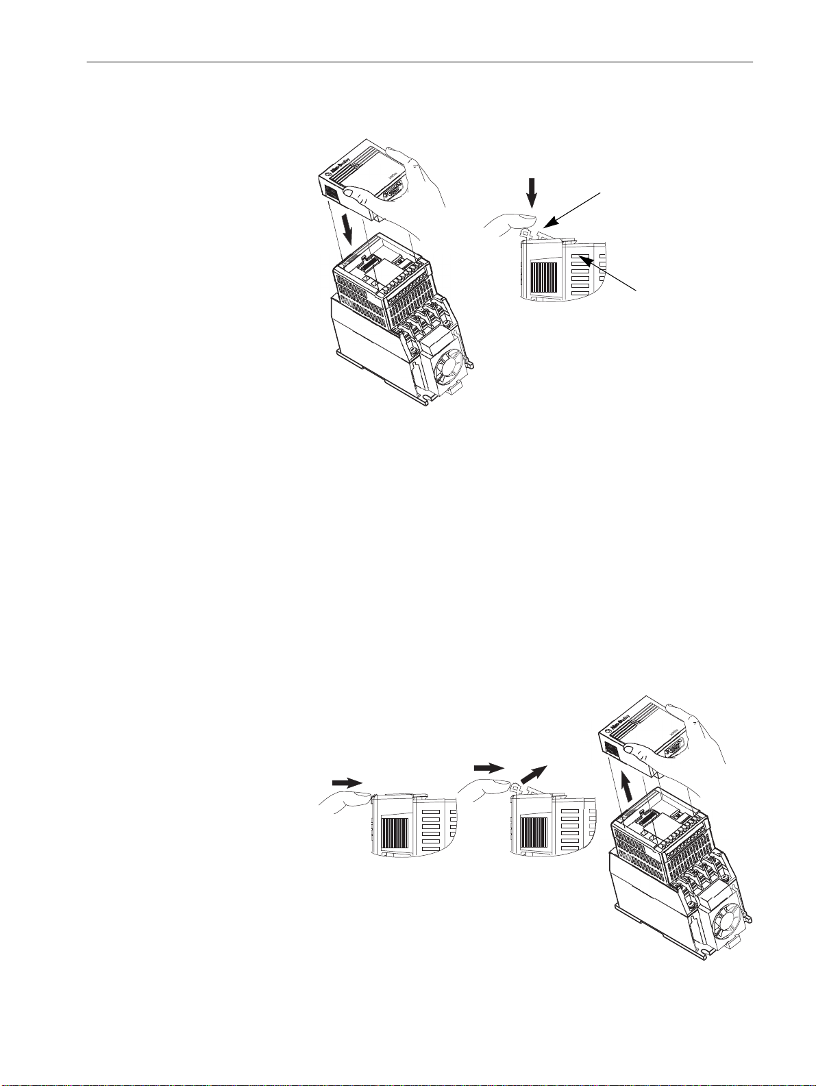
Figure 3.2
Communication Module Installation
Removing the IB1 Module
Installation and Wiring 3–3
Latch must be in this position before
installation. Once installed, push the
latch down until it locks into place.
Module should be flush
with top surface of drive
If you need to remove the module from the drive, you must
1. Verify that all power to the drive is removed. Review Attention
statement on page 3–2.
2. Disconnect the cable/connector from the module (if present).
3. Press in on the module’s latch and then push away and up.
4. Grasp the module and pull straight up. Avoid bending or twisting
the contact p ins loc at ed under neath the cen ter portion of the
module.
Figure 3.3
Removing the Communication Module
Page 14

3–4 Installation and Wiring
Wiring the Dri ve Terminal Block
The 160 drive and 160-IB1 interface can be controlled on a network
in 2 different mod es.
[Input Mode] = 2
This mode is used where the dr i ve is controlled sol ely by the netw ork.
The 160-SSC drive requires, that a stop signal is present on the
hardware terminals, before the drive can be started.
Control
ether a wire bridge or a normally closed stopping device.
Fitting a stopping device (e.g. pushbutton) in place of the link,
can provide addition al lo c al stop/emergency stop capability.
Important: Failure to link the stop command input, will result in the
[Input Mode] = 6
This mode is used whereby it is possible to cont rol the drive across
the network or locally, by putting a switch on the Control Terminal
Block 3 (TB-3) pins 7 & 8.
When the switch is closed, the Frequency source comes from th e
reference as defined by P59 - [Frequency Select]. As we are using
the 160-IB1, the reference is across t he Interbus network.
Additionally the start command is active across the network.
Terminal Block 3 (TB-3) pins 7 & 8 need to be linked by
drive generating a fault, and inability to run accross a
network.
When the switch is open, the Frequency source comes from the
terminal block (analogue reference or potmeter), regardless of the
setting of f P59 - [Frequency Select]. Additionally the start command
is controlled by the terminal block or keypad.
Page 15
Installation and Wiring 3–5
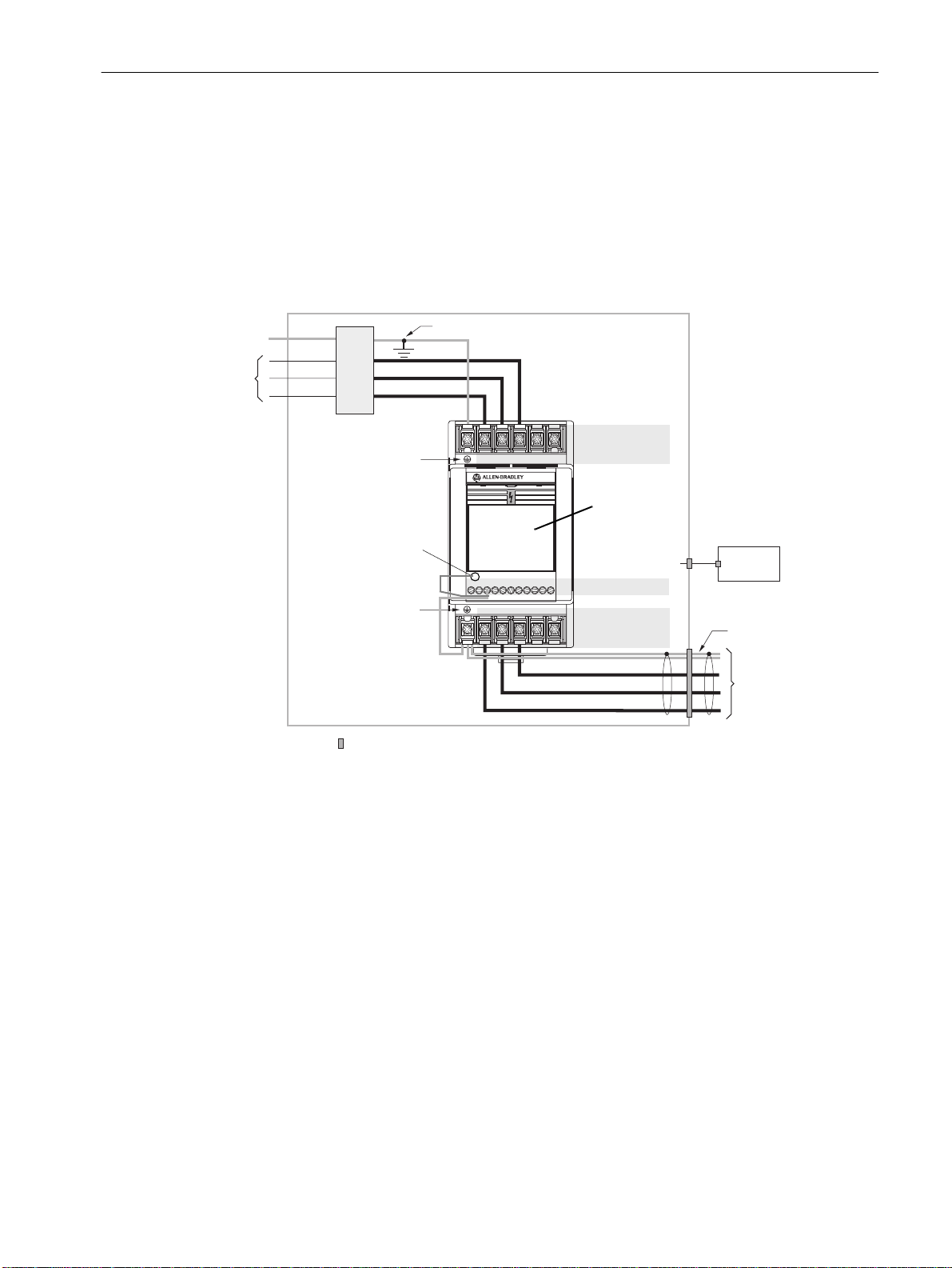
Wiring the IB1 Ground Terminal
PE
T (L3)
AC
nput Line
S (L2)
Filter
R (L1)
Ground T erminal – PE
IB1 Ground Terminal
Ground T erminal – PE
In addition to the ground connections shown in Appendix C of the
160 SSC manual, the ground terminal at the bottom of the IB1
module must be solidly connected (and as short as possible) to the
signal common terminal 3 at TB3 of the 160 SSC drive, as shown in
Figure 3.4:
2
This connection shall have a cross section of 1.5 mm
Figure 3.4
IB1 Module Grounding
Enclosure Ground Connection
Line
T/L3
S/L2
R/L1
R/L1
S/L2
T/L3
BR–
Line Power TB1
BR+
IB1 Communication
FAULT
READY
1
45678910112
3
V/T2
U/T1
W/T3
DC–
DC+
Module
to TB3
Control Wiring TB3
Motor Wiring TB2
.
Control
Cabinet
➊
Shielded Motor Cable
Shielded Enclosure
= EMC Tested Shielded Cable Clamp (or Metal Conduit)
➊
When the control circuitry is located outside of the 160 enclosure.
W/T3
V/T2
U/T1
to Motor
Page 16

3–6 Installation and Wiring
Wiring the Connectors
The example in F igure 3.7 can be use d as a guide when wiring.
Important: Keep communi cat i on w i ring away fro m high noise
sources suc h as motor cab l es .
Figure 3.5
Wiring the IB1 Connectors
9-Pin, Female D-Shell Co nnector (NEXT)
Ground Connection
Terminal
Pin 1
9-Pin, Male D-Shell Connector (IN)
Pin 9
Note: For better visibility of the status LED's it is recommended to
use a cable inline with connector (180° not 90°).
Figure 3.6
Remote Bus Cable Termination
/DO 6
DO 1
/DI 7
DI 2
COM 3
9
5
green
yellow
pink
gray
brown
6 /DO
1 DO
7 /DI
2 DI
3 COM
Male end via strain relief Female end
(Grounding Clamp)
Note: Wire colors may vary depending on cable manufacturer
Page 17

Installation and Wiring 3–7
Connecting the Communication Cable to the Module
PLC
m
InterBus
Master
Follow these steps to connect your module.
1. Verify that the cable/connector is correctly wired
(See Figure 3.6).
2. Locate the D-shell (IN) connector at the base of the IB 1 Module.
3. Plug cable /connector into the IB1 D-shell connector and secure.
4. Extend the network via the D-shell
(NEXT) connector on the front.
5. Last IB1 of network, D-shell (NEXT) conn ector must be left
empty for the network to be correctly terminated.
Figure 3.7
Remote Bus Connection
Remote Bus
InterBus
SSC160-C
f
Master Interfaces:
mm
ff
InterBus
SSC160-C
InterBus
SSC160-C
f: female connector
m: male connector
Page 18

3–8 Installation and Wiring
End of Chapter 3
Page 19

Chapter
Modes of Operation
Chapter 4 contains the following information:
• Powering up the drive with the IB1 Module installed.
• The modes of operation and LED indications.
4
Powering Up the Drive
LED Indicators
After you ha ve ins talled the IB 1 Module, a pply po wer to the dr i ve and
to the connected device. The READY LED should illuminate.
If it does not, refer to Chapter 8, Troubleshooting.
The IB1 Module has five LEDs (see figure below) which provide
module status.
BA LED
RC LED
TR LED
FAU LT LED
RD LED
The LEDs are defined as follows:
• Four Communication Status LEDs – These LEDs have the
following functions:
RC (yellow): Remote bus Check (Input cable connect ion o.k. )
BA (green): Bus Active
TR (green): Transmit/Receive (PCP Communication active)
RD (red): Remote bus Disable (Output cable connection
missing)
•FLT (red) – This LED tracks the fa ult status of the 160 Drive.
When no faults a re present, the LED will be off. The LED will
illuminate (red) if a drive fault occurs.
For more information refer to Table 8.A.
Page 20

4–2 Modes of Operation
Operation Modes
The IB1 Module has three modes of operation.
• Power- up mode
• Run mode
• Error mode
Power-up Mode
If the power-up sequence is successful, the modul e enters the run
mode (RC LED on) and the TR LED flashes green.
If the power-up sequence fails, the TR LED will go to off and the
module will enter the Error Mode (see below).
Run Mode
After a successful po wer -up, th e IB1 Module enter s the run mode and
operates as a slave device to a master device (BA LED on).
The RC LED i s o n , i n dic at ing the receiving of messages.
In run mode, the module:
• Accepts and responds to messages from the master on the
network.
• Monitors cable integrity an d t ransmission performance.
TR LED is on in case of PCP messages are exchanged. If an error is
detected, the module enters Error Mode (see below).
Error Mode
If the module detects an error, the fault is indicated by the FLT LED.
Refer to Chapter 8 for details on how to recover from an error.
Page 21

160 S S C Dr ive Parameters
Parameter Number
Drive IB1
Index; Subindex
46 0x5FF0; 46
0x5FF9; 46
59 0x5FF0; 59
0x5FF9; 59
66 0x5FF0; 66
0x5FF9; 66
Access [Parameter Name] and Description
Read
Write
Read
Write
Read
Write
Chapter
InterBus Parameter Descriptions
and Data Protocol
This chapter provides a listing and description of the Bulletin 160
Drive parameters related to Networ k Operation, and the IB1 Module
Data Protocol information.
Important: Refer to your 160 S SC™ Varia ble S peed Dri v e (Serie s C)
User Manual for drive parameter descriptions.
[Input Mode]
Configures the TB3 control inputs for various 3-wire or 2-wire control schemes.
Also enables/disables the program keypad module input control.
Settings: must be set to either
2 = Program Keypad Module control or
6 = 2-wire TB3 Control/Keypad or Communication control
A contact closure on TB3 terminals 7 and 8 is required for the drive to respond to a
Run command.
Important: This parameter cannot be programmed while the drive is running.
In addition, power must be cycled or P56 - [Reset Function] must be
set to 2 for the change to take effect.
[Frequency Select]
Selects the source of the frequency command for the drive.
The reference to P58 - [Internal Frequency] is bipolar, so a positive reference gives
forward rotation, and a negative reference gives reverse direction.
Settings:must be set to 1 = internal freq. command from P58 - [Internal Frequency].
[RPM Scaling]
A scaling factor is required to interpret a speed reference in RPM at the [Maximum
Frequency] of the drive. The 160 Drive parameter P 66 - [Preset Frequency 5] is
used by the IB1 Module for this purpose.
P66 = rRPM / rf
rf: required motor frequency to achieve rRPM
rRPM: final RPM at applicat ion output (e.g. speed at gear box output),
which will be displayed at InterBus Master.
Application Speed [rpm] = Drive Output Frequency x P66 [RPM Scaling]
e.g. 1500 rpm = 50 Hz x 30 (4 pole motor) P66 = 30.0 (300)
Gear Box 1:20: 75 rpm = 50 Hz x 1.5 (4 pole motor) P66 = 1.5 (15)
For network operation the P66 values in brackets are valid, which are ten times the
values for key pad operation.
If P66 - [RPM Scaling] is set to 0, speed reference may be sent via the network
directly in 1/10 of Hz.
e.g. SpeedRef [Hz] (InterBus) = 405 results in 40.5 Hz of output frequency.
Speed feedback is considered to be P01 - [Output Frequency],
which reflects the output frequency considering ramp rates.
5
Min./Max.
Values Default
0/9 0
0/1 0
0-240
[0-2400]
50
ATTENTION: Unpr edictable motor speed can cause de ath,
injury or equipment damage. Do not use P66 as the [Preset
!
Frequency 5] function via control terminal wiring.
Note:
P57 [Program lock] may be set to 1 (locked), but parameter programming via network will still be possible.
Page 22

5–2 InterBus Parameter Descriptions and Data Protocol
InterBus Data Protocol
Data Channels
The data transfer in Interbus terminology is called Peripherals
Communications Protocol (PCP).
Process data and parameter data is transmitted in the InterBus system
via two independant transmission chan n els. i.e. the process data
channel and the parameter data channel.
The process data ch annel cyclically transmits process data in the
form of an I/O image. This image contains the logic control word to
start /stop the drive, and the reference to c ontrol the speed, which is
used in the appli catio n progr am to control the dri v e. Ad ditio nally th is
image receives the drive status word, and the speed feedback word,
which is used in the application program to monitor drive operation.
Together with a diagnostics register, this results in three registe rs
being transmitted to and from the drive (see table 5 A & B). This
direct memory access to control the drive is both simple and quick.
The parameter data channel only transm its data if necessary, and is
integrated into the transmission protocol being handled by the
InterBus master. When the parameter data channel is used, the master
inserts a frame of inform ation to send to the dri ve requ esting dif f erent
actions (see table 5E). This frame of informa tion requests a read or
write parameter/attribute which can take several physical cycles of
read/write with handshaking to implement, resulting in much slower
access th an t h e pro ces s da ta cha n n el .
Data from InterBus Master to IB1 S l ave
Thus the combination of the faster process data channel for control,
and the slower parameter data channel, optimises the data
transmission.
A scaling factor is req uired to inte rp ret a speed re ference in RPM .
The 160 Dri ve par amete r P66 - [Preset Frequency 5] is used by the I B1
Module for this purpose. See “160 SSC Drive Parameters” on page1.
ATTENTION: Unpredictable motor speed can cause
death, injury or equipment damage. Do not use P66 as the
!
[Preset Frequency 5] function via contro l t e r mina l wiring.
Table 5.A
Register No. Register (Words) Description
0 Control Word According to DRIVECOM 20
1 Speed Reference Speed reference in RPM
2 Diagnostics reserved
Page 23

InterBus Parameter Descriptions and Data Protocol 5–3
Data from IB1 Slave to InterBus Master
Control and Status Word DRIVECOM 20/21
Speed Feedback, displa yed by Register 1, is scaled in RPM according
to P66 - [RPM Scaling].
Table 5.B
Register No. Register (Words) Description
0 Status Word According to DRIVECOM 20
1 Speed Feedback 160 Drive Output Frequency (motor RPM)
2 Diagnostics reserved
Control an d St at u s w or d b its ar e defined as follo ws (speed control):
Table 5.C
Control Word (Bit definition)
Bit No. DRIVECOM 20 Control SSC160
0 Switch-on 1 = Switch-on
1 Disable voltage 0 = Disable
2 Fast Stop 0 = Stop
3 Enable Operation 1 = Enabled
4 reserved
5 reserved
6 reserved
7 Reset Fault 0 to 1 Transition = Reset
8 to 15 reserved
To start the drive, set the control word (Low Byte) from 6 t o Fh.
To stop the drive, set the control word (Low Byte) to 6.
T o c ont rol the dr i ve via Terminal Block (T B3), the Control Word Low
Byte must be set to 06h (state READY TO SWITCH ON).
Table 5.D
Status Word (Bit definition)
Bit No. DRIVECOM 20 Status SSC160
0 Ready to switch-on 1 = Ready
1 Switched-on 1 = Switched-on
2 Operation enabled 1 = Enabled
3 Fault 1 = Fault
4 Voltage-disabled 0 = Disabled
5 Fast stop 0 = Stop
6 Switch-on-disabled 1 = Disabled
7 reserved
8 reserved
9 Remote 0 = Local
10 Speed Ref. Reached 1 = Speed Ref. Reached *
11 Speed limited 1 = Speed limited *
12 reserved
13 reserved
14 Reverse Disabled 1 = Reverse Disabled
15 Direction 1 = Reverse (running)
* Internal speed reference/feedback is computed in 0.1Hz increments.
Due to rounding issues speeds in RPM may differ.
Resolution error in RPM = P66 * 0.05.
Example: for P66 = 16.6 the possible error is 1 RPM.
Page 24

5–4 InterBus Parameter Descriptions and Data Protocol
Drive State Transitions
SWITCH ON DISABLED
(Power-up and diagnostics o.k.)
9
Disable voltage
xxxx xx0x
8
Shutdown
xxxx x110
2
xxxx x110
READY TO SWITCH ON
(No interlock)
Switch on
3
xxxx x111
SWITCHED ON
(Driv e enable inter l o ck)
The following Figure 5.1 shows the most important state transitions
Figure 5.1
State Diagram
DRIVE FAULT
00x1'1000
1
01x0'0000
Disable voltage
7
xxxx xx0x
Fast stop
xxxx x01x
Disable voltage
xxxx xx0x
10
Fast stop
xxxx x01x
0011'0001
Shutdown
6
xxxx x110
0011' 001 1
15
12
Reset fault
0xxx xxxx
to
1xxx xxxx
Disable voltage
xxxx xx0x
Enable operation
4
xxxx 1111
OPERATION ENABLED
(RUN commanded)
State Transition Names
Dri ve S ta t e Names
with associated
and
Numbers
Shutdown
5
xxxx 011x
0011' 011 1
with associated
Status Words
11
FAST STOP ACTIVE
Fast stop
xxxx x01x
(Low Byte) appear inside the boxes
(Decel erate to 0 frequ.)
Control Words
(Low Byte) appear outside the boxes
0001' 011 1
State Transition Description
Triggered State
Transi tion Name
Disable voltage
Transit ion
7, 9, 10, 12 xxxx xx0x Stop operation (current loop off) from any STATE and after FAST STOP ACTIVE.
(High priority stop)
Shutdown
2, 5, 6, 8 xxxx x110 Command to get to READY TO SWITCH ON after SWITCH ON DISABLED or fault
(Stop command)
Switch on * 3 xxxx x111 Command to get (from READY TO SWITCH ON) to SWITCHED ON state can be
Fast stop 7, 10, 11 xxxx x01x Stop as fast as possible (with current )
Power-up successfull * 1 Needs no command as it is done inside the module itself
Enable operation 4 xxxx 1111 Start the drive if previous states are SWITCHED ON or READY TO SWITCH ON.
Reset f ault 15 0xxx xxxx t o
Control Word
Bit 7..... Bit 0 Description
reset. Command to stop the drive if it is running.
replaced by Enable operation for running
Comand to clear a present fault
1xxx xxxx
* These transitions are not needed for operation.
Note: The state SWITCHED ON is like power on to the drive, but this is a virtual state because the power to
the drive is applied all the time in our case.
Page 25

InterBus Parameter Descriptions and Data Protocol 5–5
P arameter Access
Parameter acces s i s establish ed b y object indices and parameter
related sub- ind i ces to be sent via the PCP telegram.
Table 5.E
Parameter
Type
Display P01 – P20,
Program P30 – P84 0x5FF1 1 – 86 (84) Read Parameter Default
Program P30 – P84 0x5FF2 1 – 86 (84) Read Parameter Low Limit
Program P30 – P84 0x5FF3 1 – 86 (84) Read Parameter High Limit
Program P30 – P84 0x5FF4 1 – 86 (84) Read Parameter Attribute
Program P30 – P84 0x5FF9 30 – 86 (84) Write
Fault Code 0x603F Active Fault according to Table 8B
Parameter
Numbers Index Sub-Index (decimal)
0x5FF0 1 to 99(1-20, 30-84) Read
P30 – P84
Parameter attributes
Each parameter is described by an attribute to be read according to
table 5.F. The attribute consists of one word with 2 bytes which are
defined as follows:
High Byte stores the Unit (scaling) according to the ta ble 5.G,
Low Byte stores the parameter number.
Table 5. F
High Byte Units
0 Decimal 1
1 Decimal 0.1
2 Decimal 0.01
3 Hexadecimal 1
4 Binary 1
5 Decimal (signed) 1
6 Decimal (signed) 0.1
7 Decimal (signed) 0.01
Parameter Access Fault Codes
("Additional Error Codes")
The error messages listed in the table 5.G indicated problems when
attempting to access parameters via PCP.
The drive will NOT fault but indicate to the user that a specific
parameter access failed.
Table 5.G
Error Code Error
1 Parameter size is too small (e.g. byte instead of word)
4 Parameter value is out of limits
10 Parameter write attempt while drive is running
11 Parameter number too small
12 Pa rameter size is too large (e.g. 3 bytes instead of two bytes)
20 Parameter number not valid
22 Parameter number is too high
30 No valid response from drive
Page 26

5–6 InterBus Parameter Descriptions and Data Protocol
Communication Statistics
The following communication statistics can be read via the InterBus
Register 3 from the Networ k opt ion.
Table 5.H
Write Read
Decimal Hex Statistics
0 0 Background task counter
14 E Total PCP messages received
15 F Total PCP message errors received
16 10 Total PCP messages sent
17 11 Total PCP message errors sent
18 12 Total PCP protocol aborts
Others Diagnostics
Page 27

Chapter
6
Using the 160-IB1 on InterBus
The purpose of this chapter is to provide an example of the steps
necessary to use the 160-IB1 on an InterBus network. As InterBus is a
3rd party network, we will be usi ng a n SST-IBS-SLC scanner to act as
a master for InterBus, residing in an A-B SLC500 rack.
The SST scanner sends I/O messages periodically to a Bulletin
160-IB1 to start and stop the drive and control its speed. Additionally
the Bulletin 160-IB1 responds to these I/O messa ges by sending
status messages and speed feedback back to the scanner. In this way
the ladder logic program in the A-B SLC500 PLC can control the
drive .
The Bulle tin 160-IB1 also s uppor t s an Inter B u s t e legr am w hi c h c a n
be used to configure or read parameters from the drive.
This chapter contains the following information:
• How to create an InterBus network configuration frame.
• A sample ladder logic program to control the Bulletin 160 SSC
using I/O messaging
• A description of the InterBus PCP telegram.
• A sample ladder logic program to execute the PCP telegram
Required Tools
The SST-IBS-SLC scanner for the SLC500 is used in the exampl es in
this manual. However the concepts demonstrated in the examples
apply to any InterBus master.
The following too l s are needed to comp l et e this chapter.
• Bulletin 160 series C equipped with a 160-IB1 InterBus
communication module
• SLC500 processor with a digital input card to issue start & stop
commands
• Phoenix IBS CMD SWT G4 software to configure the scanner
and a null modem RS232 serial cable.
Page 28

6–2 Using the 160- IB1 on InterBus
Creat e an Inte rBus Network Configuration Frame
This example assumes that the SLC 500 rack has been configured
correctly with the SST-IBS-SLC card in slot 3. If configuration is
required an example of configuration is shown further in this chapter
– The InterBus PCP Telegram. Additionally it is a ssumed that a
160 drive with an 160-IB1 interface is connected on the Int erBus
remote bus with a relevant 9 way D shell connector (see chapter 3).
Invoke Phoenix IBS CMD software and create a new proj ect with
”File Menu” and ”New”.
Go to extended mode,.
then to the ”Settings” mode. On the ”Settings” dialogue box select the
Drivers tab and select the ”co mmunication path” button.
In this example, the connection to the SST scanner is via a null
modem cable from the serial port on C O M 1 at 9600 baud.
Adjust the path accordingly and click OK twice.
Page 29

Using the 160-IB1 on InterBus 6–3
Click (select) the controlle r board and right mouse click ”type” to
select the type of scanner.
Click IBS USC(4K) as the controller type and click ok.
With the ”controller board” selected, hit F3 on your PC (the state
button). Select Configuration (on-line) and click ok. If the processor
is faulted, you will not be able to go on-line. So p u t the processor int o
program mode with the keyswitch., then select Configuration
(on-line).
Now select ”configuration” and ” configuration frame” and ”read in ”
the network that is attached to the scanner.
You will probably get the message that the paramet eris a tio n o f the
controller board will be lost. This is ok because it was not valid
anyway. Select Yes.
Also you may get the message that the software is unable to read the
parameter channel settings. Select OK to continue.
In this case you see one module has been identified as a DRIVECOM
assembly with InterBus library identifier 227.
Page 30

6–4 Using the 160- IB1 on InterBus
.
Look at the LED’s on the 160-IB1 module, BA is flashing, indicating
that the module is not being controlled by anything.
Now with the controller still selected, right click and choose
”Parameterization” and ”Edit” to specify how we want the scanner to
start up.
Select ”S t art u p w i t h out PDP” and uncheck ”star t data transmi s si o n ”
(action 23) an d click ok.
Page 31

Using the 160-IB1 on InterBus 6–5
Now save the file wit h a filename. Choose ”File” and ”Save”
commands.
The network should now be configured with the 160-IB1 BA LED
now steady green. If not , check that the processor is in Run mode.
InterBus assigns a communication reference (CR) dynamically when
the network(frame) is read in. It starts with the first module it sees on
the network, assigns a CR=2 and specifies memory alloc ation for the
I/O messaging. Then the CR and memory allocation increments for
each module it sees. Therefore any new nodes added to a network
should ALWAYS be added to the end of the network.
In order to view t h e memory allocation, select ”Monitor” and
”Controller Board” and ”Address Monitor”.
The 160-IB1 with the DRIVECOM 20/21 implementation is mapped
3 words input and 3 words output, mapped to the start of the memory
of the scanner card. In this case as the IBS scanner is in slot 3 of the
SLC rack, then address 0 is the first output address of the card i.e.
O:3.0.
Outputs
Address 0 C ommand word
Address 1 Speed reference
Address 2 Diagnostics
Address 512 (Inputs) are the first input addresses of the scanner card :
I:3.0
Address 0 Status word
Address 1 Speed feedback
Address 2 Diagnostics.
Page 32

6–6 Using the 160- IB1 on InterBus
Controlling the Drive with I/O Messaging
Now adjust the drive parameters as defined in chapter 5 of this
manual in order to test the driv e with the following program example:
Figure 6.1
Drive Test Program Ladder Logic Example.
Ladder diagram continued on next page
Page 33

Using the 160-IB1 on InterBus 6–7
Drive Test Program Ladder Logic Example (continued)
Page 34

6–8 Using the 160- IB1 on InterBus
The InterBus PCP Telegram
The Peripherals Communication Protocol (PCP) of InterBus supports
2 different type s of independent data transmission.
The 3 words tha t were mapped previously in this chapter, is the
process data channel which is the cyclic transmitted I/O data to start/
stop the drive and provide reference and feedback. The parameter
data channel is mu c h slower, working a r ound the process data
channel, to read/write parameters to the drive.
The param et er dat a channel i s handl ed b y th e In ter B us master and
transmits a frame of infor ma tion only when required.
This form of me ssaging i s per formed by cop ying data to and fr om the
SST-IBS-SLC card M0 and M 1 files . Therefore the SS T-IBS-SLC
card needs to be setup to support the PCP telegram.
If starting from scratch create a new project using RSLogix500
software and select the I/O Configuration to specify the processor,
Digital Input card and SST-IBS-SLC. If you are using an existing
configuration you will need to modify to suit.
Note that the example configur ation below has an additi onal SST card
in slot 2. This is not used in the following example.
The Scanner is configured for the rack with generic ID = 13635.
Page 35

Using the 160-IB1 on InterBus 6–9
Select the Advanced Config button, to setup the card as shown. This
means th at t here are 32 words reserved for pro cess data (I/O) and the
M files are set to 384 words. To make PC P functi on we need to setup
the G files with data . So the G files length = 7.
Select the Edit G file data button, to setup the data for the In t erB us
telegram. (see SST-IBS-SLC user manual for details)
Word 0 is fi xe d by the SL C
Word 1 bit 12=1 (4096)
Word 5 defines where M files stop for I/O and where M files start for
PCP (22 5)
Wo rd 6 Com mand buffer size for PCP
These values are just an ex ample of setup and t h e SS T-IBS-SLC user
manual should be consulted to optimise the PCP s etup.
Download this I/O conf iguration to the SLC. The card is now setup to
communicate with the InterBus telegram.
How it works
The number of words to be setup in the M files, varies as the type of
message to be transmitted. In the sa m pl e program follow ing , t he M
files are being copied to integer files so we can easily send/receive
data.
N7:70 is M0:3.225 onwards – the output data to the drive
N7:80 is M1:3.225 onwards – the input data fr om the drive
Page 36

6–10 Using the 160- IB1 on InterBus
This is an example of a read drive parameter (all values in hex)
The first node on the networ k is a communication r efer ence (CR) = 2,
with the para meter read access index of 5FF0 (see table 5E) and th e
sub-index s p eci fyi n g parameter 8 [H eatsink Temperature].
Once transmitted, the response in
N7:80 provid es an echo of the command word
N7:81 number of words following
N7:82 CR
N7:83 result of comms 0=success
N7:84 number of bytes read (in this case 1 word)
N7:85 data read 45 hex = 69 decimal which is the normal value
registered on the heatsink, when temperature is below it.
This is an example of a read attribute drive parameter
(all values in hex)
The first node on the networ k is a communication r efer ence (CR) = 2,
with the parameter read attribute access index of 5FF4 (see table 5E),
and the sub- ind ex sp eci fy i n g parameter 30 [Accel Time 1].
Once transmitted, the response is similar to above:
N7:85 LSB of 1E is parameter 30, MSB of 1 is multiplier
(see table 5F).
This is an example of a write attribute drive parameter
(all values in hex)
In this example the w rite access index is 5FF9 (see table 5E) and the
sub-index s p eci fy in g parameter 30 [ Acce l T ime 1].
N7:73 specifies the number of bytes to write
N7:7 4 is the data to writ e
N7:80 provid es an echo of the command word
N7:81 number of words following
N7:82 CR
N7:83 result of comms 0=success
N7:84 & N7:85 are not valid, being values that were updated on the
read at tr ibute exercise.
Page 37

Using the 160-IB1 on InterBus 6–11
Reading and Configuring Parameters wi th the PCP Telegram
Figure 6.2
PCP Telegram Ladder Logic Example
This program example can be made to operate by first setti ng I:1.4 to
request a read or write ope ration, t he set ting B3:20 b it 0 t o 1 to upd ate
the data in N7:70 onwards into the M0 files, the n setting B3:20 bit 1
to 1 to send the data.
Ladder diagram continued on next page
Page 38

6–12 Using the 160- IB1 on InterBus
PCP Telegram Ladder Logic Example (continued)
Page 39

Chapter
7
Controlling the Drive
Controlling the 160 Drive from a programmable controller is
accomplished using Message Commands to communicate through
the IB1 Module to the drive . To send a Start or Stop command to the
drive, the corresponding control bits in the DRIVECOM Control
Word must be set.
Setting the Drive to Enab le Network Control
The 160 Drive must be configured to accept logic and speed
commands from the network. This is done by configuring three
parameters:
1. Set P46 - [Input Mode] to a value of “2” or “6” as described in the
following Table. This will configure the drive to accept the logic
commands from the network.
Important: The d rive may be op e r a t ed in other mo des as long as
the InterBus Master provides an Enable command
(control w o rd = 0x6)
2. Set P59 - [Frequency Select] to “1.” This will configure the drive
to accept speed comman ds from the network .
3. Set P66 - [RPM Scaling] according to rated nameplate s peed.
(See chapter 5 for details).
Changing the above parameters can be done with the 160 Keypad
Module or configuration software such as DriveExplorer.
Important: For a new Input Mode to take af fect, dr i ve pow er must be
cycl ed o r para mete r P56 - [Reset Functions] must be set to
“2” instead.
Page 40

7–2 Controlling the Drive
End of Chapter 7
Page 41

Chapter
Troubleshooting
The purpose of this chapter is to help you troubleshoot your IB1
Module.
ATTENTION: Servicing energized industrial control
equipment can be hazar dous. Electrical shock, burns, or un-
!
intentional actuation of controll ed industrial equipment
may cause death or serious injury . Follow th e safety-rel ated
practices of NPFA 70E, Electrical Safe ty for Employee
Workplaces, when working on or near ener gized equipment.
Do not work alone on energized equipment.
ATTENTION: Do not attempt to defeat or override fault
circuits. T he cause of a fault indicati on must be determined
!
and corrected before attempting operation. Failure to
correct a dri ve or system malfunct ion may result in personal
injury and/or equipment damage due to uncontrolled
machine system operation.
8
Setup
LED Indicators and Troubleshooting
Make sure parameters P46, P59 and P66 have been set accord i ng to
chapter 5.
The IB1 Statu s LEDs can hel p you troubleshoot the modul e in the
event that problems occur. Refer to t he paragraphs that fo llow for
details.
Status LEDs
Refer to Chapter 4 for
detailed LED descriptions
Page 42

8–2 Troubleshooti ng
Communication Status LEDs
In case no LED i s o n , chec k t h e op t i o ns co n n ect ed t o the S SC160.
The four Communication Status LEDs provide status information on
module operations. Table 8.A shows how to use the LED to detect and
correct common operating problems.
Table 8.A
Communication Status LEDs Indications
Name
(Function) State What It Means: What To Do:
RC
(Remote Bus
Check)
BA
(Bus Active)
TR (Transmit/
Receive)
RD
(Remote Bus
Disable)
Off No power, processor reset,
InterBus reset or network link to
predecessor in line interrupted
yellow Input cable connection o.k. No action require d.
Off Bus inactive Check InterBus Master setup.
green Bus Active / Data exchange No action required.
Off No PCP Communication If PCP operation is desired, check
green PCP Communication active No action required.
Off Outgoing InterBus enabled No action required.
red InterBus Reset or outgoing Bus
disable
Check Power Supply, Network
Cable and InterBus Master
operation.
IB Master setup (initiate PCP).
No action required on last device
in line (emty top plug). Otherwise
check cabling and reset Master.
FLT LED
When the FLT LED is red, a drive fault is present.
Table 8.B
)
InterBus Faults (DRIVECOM 20
Fault No.
[Hex]
0 no fault 0
1000 General Malfunction nn
2200 Internal Current 13
2300 Current on Device Output Side 12
2320 Current on Device Output Side: Short Circuit/ Eart h Leakage 46
2331 Current on Device Output Side: Earth Leakage Phase U 38
2332 Current on Device Output Side: Earth Leakage Phase V 39
2333 Current on Device Output Side: Earth Leakage Phase W 40
2341 Current on Device Output Side: Short Circuit Phases U-V 41
2342 Current on Device Output Side: Short Circuit Phases V-W 42
2343 Current on Device Output Side: Short Circuit Phases W-U 43
3210 Internal Over Voltage 5
3221 Internal Under Volta ge No. 1 3
3222 Internal Under Volta ge No. 2 4
4210 Excess Temperature Device 8
4310 Excess Temperature Drive 20
5000 Model of drive not valid
5300 Device Hardware: Operating Unit 11
5310 Device Hardware: Data Storage RAM
5320 Device Hardware: Data Storage EPROM
6100 Device: Internal Software 32
6200 Device: User Software 33
6320 Device Software/ Data Record: Parameter Error 48
7500 IBS fatal protocol error
Fault Name Fault Code
in Object 603F
SSC160 [Dec]
Page 43

Troubleshooting 8–3
Fault No.
[Hex]
7510 Serial interface to drive timeout
7520 Serial interface IBS bus not active
8100 Monitoring: Communication 36
8311 Monitoring/ Torque Control: Excess Torque 7
8313 Monitoring/ Torque Control: Standstill Torque 6
Fault Name Fault Code
SSC160 [Dec]
Drive faults can be re ad via index 0x603F. Refer to Table 8.C Table
8.D for fault n u m ber rel a tion.
Drive fault codes can be read by accessing drive parameter P07 - [Last
Fault]. Refer to Table 8.C and Table 8.D for f ault descriptions/actions.
Table 8.C
160 Drive
Fault Code Fault Indication Description Corrective Action
00 No Fault The d r ive is currently not faulted. No action required.
03 Power Loss Fault DC Bus voltage remains below 85% nominal on
power up for longer than 5 seconds.
04 Undervoltage Fault DC Bus voltage fell below the minimum value while
05 Overvoltage Fault DC Bus maximum voltage exceeded. Bus overvoltage caused by motor regeneration. Extend
06 Motor Stall Fault Motor has stalled. Motor load is exce ssive. Longer accel time or reduced load required.
07 Motor Overload Fault Internal electronic overload trip. Excessive motor
08 Overtemperature Fault Excessive heat detected. Clear blocked or dirty heat sink fins. Check ambient
11 Operator Fault The keypad has been removed while the drive is
12 Overcurrent Fault Overcurrent detected in hardware trip circuit. Check short circuit at the drive output or excessive load
13 Software Over
Current Fault
20 Drive Overload Fault An internal electronic overload trip has occurred.
22 Drive Reset Stop input not present. Check stop input at TB3 terminal 8.
32 EPROM Fault EPROM has invalid data. Reset EPROM using P56 - [Reset Functions].
33 Max Retries Fault Drive did not reset fault within the specified retries. Repa ir system fault.
36 Incompatible Fault Incompatible communication module installed. Verify compatibility of communication module.
38 Phase U Fault Phase to ground fault detected between drive and
39 Phase V Fault Phase to ground fault detected between drive and
40 Phase W Fault Phase to ground fault detected between drive and
41 UV Short Fault Excessive current has been detected between
42 UW Short Fault Excessive current has been detected between
43 VW Short Fault Excessive current has been detected between
46 Intermittent Phase
Fault
48 Reprogramming Fault Occurs when reset defaults is performed. Clear fault.
the motor was running.
load exists.
powered.
Motor current exceeded value set in parameter 79. A longer acceleration time, reduced load, or removal of
The drive is overheating.
motor phase U.
motor phase V.
motor phase W.
these two drive output terminals.
these two drive output terminals.
these two drive output terminals.
An external short occurred while running
diagnostics.
1
1
Fault Codes
Monitor incoming AC line for low voltage or line power
interruption.
Monitor incoming AC line for low voltage or line power
interruption.
the decel time, or install dynamic brake option or external
capacitor module.
Reduce motor load.
temperature. Check for blocked or non-operating fan.
Clear the fault. Do not remove the keypad underpower.
conditions at the motor.
motor shaft blockage is required
Clear blocked or dirty heat sink fins. Check ambient
temperature. Check for blocked or non-operating fan.
Check wiring between dr ive and motor. Check motor for
grounded phase.
Check wiring between dr ive and motor. Check motor for
grounded phase.
Check wiring between dr ive and motor. Check motor for
grounded phase.
Check the motor and external wiring to the drive output
terminals for a shorted condition.
Check the motor and external wiring to the drive output
terminals for a shorted condition.
Check the motor and external wiring to the drive output
terminals for a shorted condition.
Check wiring between the drive and the motor. Check for
more than one shorted output.
Refer to the 160 SSC™ V S D (Series C) User Manual for the most current fault code information.
Page 44

8–4 Troubleshooti ng
IB1 Network Error Codes
The following error codes could be returned when accessing the IB1
Module.
Table 8.D
Network Fault Codes
Fault Code Fault Indicati on Description Corre ctive Action
7510
7520 Unit lost Connection Timeout on serial link Check units plugs to SSC160 and IBS cable.
7500 Unit unrecov erable Fault Unexpected Network Fault
5000 Model of Drive not valid Use 160 Drive with version ’C’ or higher Replace Drive
Serial Fault
No serial Connection established Check if SSC160 of version ‘C’ or higher has been
installed. (Refer to drives nameplate).
Check 30 pin connector on the options back.
Check Parameter setting according to Section 6.
restart IBS master or d rive
Page 45

Specifications
Appendix
A
Electrical
Environmental
Communications
Mechanical
Supply Voltage Supplied by Drive
Power Consumption 1.4 Watts (280 mA) maximum
Ambient Temperature
Operating 0 to 65° C (32 to 149° F)
Storage –40 to 85° C (–40 to 185° F)
Relative Humidity 0 to 95% non-condensing
Vibrati on 1.0 G Operational
2.0 G Non-operational
Shock 15.0 G Oper a tional
30.0 G Non-operat ional
Altitude 1,000 m (3,300 ft.) without derating
Baud Rate 500 kBaud
Protocol Drivecom 20 (21)
Dimensions are in Millimeters and (inches)
(1)
17.34
(0.68)
(2)
21.4
(0.85)
(1)
Required for module removal.
(2)
Module adds this dimension to the overall drive depth.
(3)
Required for connecting cable
(3)
60
(15)
Page 46

A–2 Speci fications
End of Appendix A
Page 47

Index
B
Baud Rate
, A–1
C
Cabling
CE Complian ce
Communication Cable
Communication Statistic s
Configuration
Control W o rd
Controlling, Drive
, 3–6
, 3–1
Parameters
SST-IBS-SLC
, 6–11
, 5–3
, 3–7
, 6–8
, 6–6, 7–1
D
Data Channels
Data Protocol
Dimensions
, 5–2
, 5–2
, A–1
E
Error Mode
, 4–2
F
Fault Codes
, 8–3
Drive
Network
Parameter Access
, 8–4
, 5–5
, 5–6
M
Manuals, related
Modes of Operation
Error Mode
Power-up
Run Mode
Module Installation
, p–ii
, 4–2
, 4–2
, 4–2
, 3–2
N
Network Control, Enable
, 7–1
P
Parameter
Access
Attributes
Data channel
Descriptions
PCP Tel egram
Peripherals Communic. Protocol
(PCP)
Power-up Mode
Publications
On-line
Related
, 5–5
, 5–5
, 5–2
, 5–1
, 6–8, 6–11
, 5–2, 6–8
, 4–2
, p–ii
, p–ii
Q
Quick Start
, 2–1
I
I/O Messaging
Installation
InterBus Net wo rk
Configuration Frame
Error Codes
, 6–6
, 3–1
, 8–4
K
Keypad Removal
, 3–2
L
Ladder Logic Example
PCP Telegram
Test Program
LEDs
Communic. Status
Fault Status
, 6–11
, 6–6
, 4–1, 8–2
, 6–2
, 4–1, 8–2
R
Remot e Bus
Cable Termination
Connection
Removal, Module
Required Tools
Run Mode
, 3–7
, 3–3
, 2–1, 6–1
, 4–2
S
Scanner SST-IBS-SLC
Configuration
Description
Settings
Specifications
Communications
Electrical
Environmental
Mechanical
, 6–8
, 6–1
, 6–2
, A–1
, A–1
, A–1
, A–1
, 3–6
Page 48

Index–2
State Transitions
Status Wo rd
, 5–3
T
Troubleshooting
, 5–4
, 8–1
W
Web Sites
Wiring
, p–ii
Connectors
Drive Terminal Block
Ground Terminal
, 3–6
, 3–4
, 3–5
Page 49

Page 50

Publication 160IB1-UM010A-EN – October, 2001 P/N 899.02.91
Copyright © 2001 Rock well Automation. All rights reserved. Printed in Sw itzerland.
 Loading...