

Page 1

What This Option Provides
Where This Option Is Used
Installation Instructions
IN
Allen-Bradley
1397
Open Chassis Dynamic Brake
Cat. Nos.1397-DB-AxxxL—240VDC
1397-DB-BxxxL—500VDC
The 1397 Open Chassis Dynamic Brake kit provides a 1397 Dynamic
Brake shipped as loose parts for customer assembly
Each Open Chassis Dynamic Brake kit is sized to a 1397 drive as
detailed below.
240VAC DB Rating 500VAC DB Rating
Catalog Number
1397-DB-A001L 1.5 (1.2) — —
1397-DB-A002L 2 (1.5) — —
1397-DB-A003L 3 (2.2) — —
1397-DB-B003L — — 3 (2.2)
1397-DB-A005L 5 (3.7) — —
1397-DB-B005L — — 5 (3.7)
1397-DB-A007L 7.5 (5.5) — —
1397-DB-B007L — — 7.5 (5.5)
1397-DB-A010L 10 (7.5) — —
1397-DB-B010L — — 10 (7.5)
1397-DB-A015L 15 (11) — —
1397-DB-B015L — — 15 (11)
1397-DB-A020L 20 (15) — —
1397-DB-B025L — — 20-25 (15-18.5)
1397-DB-A025L 25 (18.5) — —
1397-DB-A030L 30 (22) — —
1397-DB-B030L — — 30 (22)
1397-DB-A040L 40 (30) — —
1397-DB-B040L — — 40 (30)
1397-DB-A060L 50-60 (37-45) — —
1397-DB-B060L — — 50-60 (37-45)
1397-DB-A075L 75 (56) — —
1397-DB-B075L — — 75 (56)
1397-DB-A100L 100 (75) — —
1397-DB-B100L — — 100-125 (75-93)
1397-DB-A125L 125 (93) — —
1397-DB-A150L 150 (112) — —
1397-DB-B150L — — 150 (112)
1397-DB-B200L — — 200 (149)
1397-DB-B250L — — 250 (187)
1397-DB-B300L — — 300 (224)
1397-DB-B400L — — 400 (298)
1397-DB-B500L — — 500 (373)
1397-DB-B600L — — 600 (448)
HP (kW) HP (kW)
&
installation.
1397-5.15 March, 1999
Page 2
1397 Open Chassis Dynamic Brake2
What These Instructions Contain
Specifications
Installation
These instructions and any accompanying instructions contain the
necessary information to assemble
install an Open Chassis 1397
&
Dynamic Brake. Each kit may be used with one or more of the 1397
drive HP ratings described on the previous page. For additional
information on wire recommendations, brake parameters and related
function blocks, refer to the 1397 User Manual.
Duty Cycle
Input Power
Enclosure Type
Altitude Derating 1,000 meters (3,300 feet) maximum without derating.
Mounting Requirements For 1397-DB-A001L-A150L and 1397-B003L-B300L kits, DB
(3) repetitive stops with an average of (1) stop every (10) minutes.
DC Power Supplied from 1397 Drive for all ratings.
For 1.5-300HP drive ratings, 120VAC customer supplied power
required for separate DB contactor operation.
For 400-600HP drive ratings, DB uses drive contactor.
IP00 (Open).
contactor must be mounted in the vertical position.
For 1397-DB-B400L-B600L kits, DB uses drive contactor.
All other DB components may be mounted as required.
ATTENTION: Electric Shock can cause injury or death.
Remove all power before working on this product.
!
The drive is at line voltage when connected to incoming AC
power. Before proceeding with any installation or
troubleshooting activity, disconnect, lockout and tag all
incoming power to the drive. Verify with a voltmeter than no
voltage exists at terminals L1, L2 and L3 on the drive input
power terminal block.
Selection
1397-5.15 March, 1999
ATTENTION: Dynamic braking resistors may be
extremely hot. Install in an enclosure or provide adequate
!
clearance to ensure that nothing can come in direct contact
with, or in proximity to the DB resistors. Failure to observe
this precaution can result in severe burns and damage to, or
destruction of, the equipment.
IMPORTANT : The National Electrical Code (NEC) and local
regulations govern the installation and wiring of the dynamic brake.
AC power wiring, DC power wiring, control wiring and conduit must
be chosen and installed in accordance with these codes and the
information supplied in the 1397 User Manual.
All Open Chassis Dynamic Brake kits include a resistor assembly and
an open cage resistor enclosure. Each resistor assembly consists of a
backplate with one or more pairs of resistors mounted in a series or in
a series/parallel configuration.
Dynamic brake kits 1397-DB-A001L — A150L and
1397-DB-B003L — B300L include a DB contactor with (1) contactor
suppressor that mounts across the contactor coil.
Dynamic brake kits 1397-DB-B400L — B600L use the drive
contactor.
Page 3

1397 Open Chassis Dynamic Brake
What This Option Provides
The DB contactors listed for the following kits require a 120VAC power
supply that will meet the specified continuous and inrush VA values
listed below. To guard against shock hazard, either the open cage
enclosure or an equivalent enclosure must be used to enclose both the
backplate and contactor.
Resistor Assembly Contactor
240VDC
DB Catalog No.
1397-DB-A001L 800160-20P 48267-P (1) Resistor 705310-100A 1.5HP/230VAC 7A/240VDC 80 10
1397-DB-A002L 800160-20R 48267-J (2) Series Connected Resistors 2HP/230VAC 9A/240VDC
1397-DB-A003L 800160-20S 48267-H (2) Series Connected Resistors 3HP/230VAC 12A/240VDC
1397-DB-A005L 800160-20T 48267-F (2) Series Connected Resistors 705310-110A 5HP/230VAC 20A/240VDC 100 11
1397-DB-A007L 800160-20V 48267-D (2) Series Connected Resistors 7.5HP/230VAC 29A/240VDC
1397-DB-A010L 800160-20W 48267-C (1) Resistor 705310-130A 10HP/230VAC 38A/240VDC 325 25
1397-DB-A015L 800160-20X 48267-A (2) Series Connected Resistors 15HP/230VAC 55A/240VDC
1397-DB-A020L 800160-20Y 48267-C (4) Series/Parallel Connected Resistors 20HP/230VAC 73A/240VDC
1397-DB-A025L 800160-20RB 48267-B (4) Series/Parallel Connected Resistors705310-140A 25HP/230VAC 93A/240VDC 325 25
1397-DB-A030L 800160-20RC 48267-A (4) Series/Parallel Connected Resistors 30HP/230VAC 110A/240VDC
1397-DB-A040L 800160-20RD 402422-3F (2) Series Connected Resistors 705310-150A 40HP/230VAC 146A/240VDC 900 55
1397-DB-A060L 800160-20RE 402422-3G (2) Series Connected Resistors 50HP/230VAC 180A/240VDC
1397-DB-A075L 800160-20RF 402422-3K (2) Series Connected Resistors 705310-160A 75HP/230VAC 265A/240VDC 900 55
1397-DB-A100L 800160-20RG 402422-3L (2) Series Connected Resistors 705310-170A 100HP/230VAC360A/240VDC 1200 70
1397-DB-A125L 800160-20RH 402422-3P (3) Series Connected Resistors 705310-180A 125HP/230VAC434A/240VDC 2900 105
1397-DB-A150L 800160-20RJ 402422-3Q (3) Series Connected Resistors 150HP/230VAC521A/240VDC
Assembly PNResistor PNDescription PN
Drive
HP/Voltage
60HP/230VAC 218A/240VDC
Motor Armature
Amps/Voltage
VA
INRUSH
VA
3
HOLD
Resistor Assembly Contactor
500VDC
DB Catalog No.
1397-DB-B003L 800160-20SP 48267-N (3) Series Connected Resistors 705310-100A 3HP/460VAC 6A/500VDC 80 10
1397-DB-B005L 800160-20SR 48267-K (3) Series Connected Resistors 5HP/460VAC 10A/500VDC
1397-DB-B007L 800160-20SS 48267-J (3) Series Connected Resistors 7.5HP/460VAC 14A/500VDC
1397-DB-B010L 800160-20ST 48267-H (3) Series Connected Resistors 705310-110A 10HP/460VAC 19A/500VDC 100 11
1397-DB-B015L 800160-20SV 48267-F (3) Series Connected Resistors 15HP/460VAC 27A/500VDC
1397-DB-B020L 800160-20SW48267-C (4) Series Connected Resistors 705310-130A 20HP/460VAC 35A/500VDC 325 25
1397-DB-B025L 25HP/460VAC 45A/500VDC
1397-DB-B030L 800160-20SX 48267-B (4) Series Connected Resistors 30HP/460VAC 52A/500VDC
1397-DB-B040L 800160-20SY 48267-A (4) Series Connected Resistors 40HP/460VAC 73A/500VDC
1397-DB-B060L 800160-20SB 402422-3D (3) Series Connected Resistors 705310-140A 50HP/460VAC 86A/500VDC 325 25
1397-DB-B075L 800160-20SC 402422-3E (3) Series Connected Resistors 705310-150A 75HP/460VAC 129A/500VDC 900 55
1397-DB-B100L 800160-20SD 402422-3F (3) Series Connected Resistors 100HP/460VAC167A/500VDC
1397-DB-B125L 125HP/460VAC207A/500VDC
1397-DB-B150L 800160-20SE 402422-3J (4) Series Connected Resistors 705310-160A 150HP/460VAC250A/500VDC 900 55
1397-DB-B200L 800160-20SF 402422-3K (4) Series Connected Resistors 705310-170A 200HP/460VAC330A/500VDC 1200 70
1397-DB-B250L 802272-53R 402422-7Z (2) Series Connected Resistors 705310-180A 250HP/460VAC412A/500VDC 2900 105
1397-DB-B300L 802272-53S 402422-7AD (2) Series Connected Resistors 300HP/460VAC495A/500VDC
1397-DB-B400L 802272-53T 402422-7AH (2) Series Connected Resistors
1397-DB-B500L 802272-53V 402422-7AL (2) Series Connected Resistors
1397-DB-B600L 802272-53W 402422-7AN (2) Series Connected Resistors
Assembly PNResistor PNDescription PN
Drive
HP/Voltage
60HP/460VAC 100A/500VDC
Motor Armature
Amps/Voltage
Not Applicable
VA
INRUSH
VA
HOLD
1397-5.15 March, 1999
Page 4
4
1397 Open Chassis Dynamic Brake
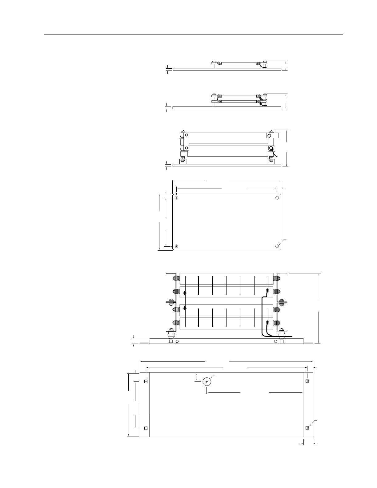
Resistor Assembly Dimensions
Side — Single Resistor — Cat. No. 1397-DB-A001L
9.65 (0.38)
Maximum Projection
45.2 (1.78)
Side — Two/Four Resistors — Cat. Nos. 1397-DB-A002L - A150L
9.65 (0.38)
Maximum Projection
90.4 (3.56)
Side — Three/Four Resistors — Cat. Nos. 1397-DB-B003L - B040L
Maximum Projection
169.9 (6.69)
9.65 (0.38)
12.7
(0.50)
508.0 (20.0)
482.6 (19.0)
12.7
(0.50)
41.4 (1.63)
508.0
(20.0)
203.2
(8.0)
177.8
(7.0)
Bottom — Mounting Panel
Cat. Nos. 1397-DB-A001L - A150L
Cat. Nos. 1397-DB-B003L - B200L
Side — Two Resistors — Cat. Nos. 1397-DB-B250L - B600L
787.4 (31.0)
749.3 (29.5)
63.5
(2.5)
Grommet Hole
47.8 (1.88) Dia.
7.92 (0.312) Dia.
— 4 Places —
Maximum Projection
397.0 (15.63)
19.05
(0.75)
1397-5.15 March, 1999
469.9
(18.5)
368.3
(14.5)
438.2 (17.25)
Bottom — Mounting Panel
Cat. Nos. 1397-DB-B250L - B600L
8.76 (0.345) Sq.
— 4 Places —
31.75
(1.25)
All Dimensions in Millimeters and (Inches)
Page 5
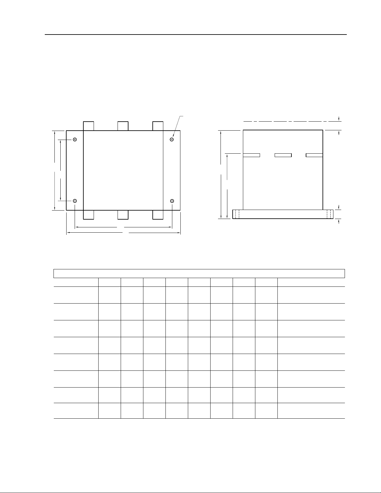
Contactor Dimensions
A
B
Mounting Hole Dia.
— 4 Places —
1397 Open Chassis Dynamic Brake
Uninsulated Wall
E
F
5
H
C
D
Top
Contactor Dimensions—All Dimensions in Millimeters and (Inches)
PN ABCDEFGHMounting Hole Dia.
705310-100A 69.1
(2.72)
705310-110A 81.0
(3.19)
705310-130A 130.0
(5.12)
705310-140A 130.0
(5.12)
705310-150A 198.0
(7.80)
705310-160A 198.0
(7.80)
705310-170A 207
(8.2)
705310-180A 272
(10.71)
59.9
(2.36)
69.4
(2.74)
100.0
(3.94)
100.0
(3.94)
140.0
(5.52)
140.0
(5.52)
140
(5.52)
200
(7.88)
35.0
(1.38)
45.0
(1.78)
90.0
(3.55)
90.0
(3.55)
120.0
(4.73)
120.0
(4.73)
160
(6.3)
170
(6.7)
43.9
(1.73)
54.0
(2.13)
102.0
(4.02)
102.0
(4.02)
136.0
(5.36)
136.0
(5.36)
182
(7.17)
198
(7.8)
118.9
(4.68)
121.5
(4.79)
137.0
(5.40)
137.0
(5.40)
168.0
(6.62)
168.0
(6.62)
178
(7.01)
226
(8.9)
76.0
(3.00)
80.0
(3.15)
95.0
(3.75)
95.0
(3.75)
103.0
(4.1)
103.0
(4.1)
107
(4.22)19(0.75)30(1.20)
140
(5.52)23(0.91)45(1.78)
0.35
(8.89)
8.9
(0.35)
21.5
(0.85)
21.5
(0.85)30(1.19)
10.5
(0.42)
10.5
(0.42)
— 4.5
— 4.5
30.0
(1.19)
15,0
(0.60)
15.0
(0.60)
Side
(0.18)
(0.18)
5.7
(0.23)
5.7
(0.23)
6.8
(0.27)
6.8
(0.27)
6.8
(0.27)
6.8
(0.27)
G
1397-5.15 March, 1999
Page 6

6
1397 Open Chassis Dynamic Brake
Open Cage Resistor Enclosure Dimensions
C
B
E
D
F
G
16.0
(.62)
7.87
(.31)
Mounting Hole
Dimension
1.52
(.06)
8.89
(.35)
1.52
(.06)
9.45
(.37)
9.65
(.38)
19.1
(.75)
19.1
(.75)
A
Mounting Tab
Dimension
H
Top/Bottom Side
Open Cage Resistor Enclosure Dimensions—All Dimensions in Millimeters and (Inches)
Drive Cat. Nos. PN ABCDEFGH
1397-DB-A001L - A150L
1397-DB-B003L - B200L
800798-54R 131.8
(5.19)
142.8
(5.62)
187.5
(7.38)
266.7
(10.50)
25.4
(1.00)
Back
46.0
(1.81)
25.4
(1.00)
241.30
(9.50)
1397-5.15 March, 1999
Page 7

Open Cage Resistor
Enclosure Dimensions
1397 Open Chassis Dynamic Brake
A
7
B
Side
Slotted Mounting Holes
Slotted Mounting Holes
C
End
Bottom
Approximate Open Cage Resistor Enclosure Dimensions—All Dimensions in Millimeters and (Inches)
Drive Cat. Nos. PN A B C
1397-DB-B 250L -B600L 802272-52S 454.0
(17.9)
752.5
(29.6)
468.3
(18.4)
1397-5.15 March, 1999
Page 8

8
1397 Open Chassis Dynamic Brake
1397-DB-A001L — A150L
B003L — B300L
Dynamic Brake Kit Operation
Dynamic braking slows down a rotating DC motor and its load. It is an uncontrolled process. During dynamic
braking, the motor armature is disconnected from the drive. A resistor is placed across the motor’s rotating
armature (now acting as a generator), and the resulting current causes braking torque in the motor. The motor
will decelerate, even with a drive malfunction, as long as motor shunt field excitation is maintained.
The drive must have the DC contactor open for dynamic braking to occur. Dynamic Braking is typically initiated
with a Coast/DB stop command or a drive fault. Under drive fault conditions, the DC contactor opens and applies
the dynamic braking grid across the armature for a dynamic braking stop.
DYNAMIC BRAKE
45
RESISTORS
DB
1
2
5
6
A1
DBR
DB RESISTOR
3
A1
MOTOR ARMATURE
A2
AC
INPUT
1397 DRIVE
181/L1
81
182/L2
82
182/L3
83
1FU
2FU
3FU
281
282
283
A1 (+)
ARMATURE
SUPPLY
45 (–)
120V AC
CUSTOMER SUPPLY
DYNAMIC BRAKE TERMINAL BLOCK
6
A1
A2
DB
2SS R
DYNAMIC BRAKE
P5-6
(34)
4
5
13
CONTACTOR
14
MOTOR SHUNT FIELD
F1
4
14
FAN
AUX
FROM
FIELD
P5-5
SUPPLY
F2
35-F237-F1
2
1
P6-5
DBCR
(33)
13
3
P6-2
DB AUX
1397-DB-A001L — A150L
B003L — B300L
Wiring
Remove and lockout all power to the drive and follow the wiring diagram above.
➊
Connect user supplied leads between drive terminals A1
If the motor has a series field, connect the motor series leads between drive terminal 45 and DB resistor
➋
terminal DBR.
➌
Connect the suppressor included with the kit between DB contactor terminals A1 and A2 and place the label
included with the kit near the contactor.
Use auxiliary contacts 33
➍
➎
Remove the jumper between terminals 3
between drive terminals 2, 3
Connect the user supplied 120VAC DB contactor power supply as shown.
➏
34 when available.
&
&
4 at the drive terminal block and connect user supplied leads
&
4 and DB contactor terminals A1, 13
&
45 and DB resistor assembly terminals 3
&
14.
&
DBR.
Refer to 1397-DB-A001L—A150L/B003L—B300L Dynamic Brake Kit Operation
above and proceed to Setup on the last page.
1397-5.15 March, 1999
Page 9

1397 Open Chassis Dynamic Brake
1397-DB-B400L — B600L
Dynamic Brake Kit Operation
Dynamic braking slows down a rotating DC motor and its load. It is an uncontrolled process. During dynamic
braking, the motor armature is disconnected from the drive. A resistor is placed across the motor’s rotating
armature (now acting as a generator), and the resulting current causes braking torque in the motor. The motor
will decelerate, even with a drive malfunction, as long as motor shunt field excitation is maintained.
When the motor is running normally, the drive’s normally-open M contacts are closed and the normally-closed
M contact is open. When the drive is connected to the motor, the dynamic braking resistor assembly is
disconnected.
For 1397-DB-B400L — B600L Kits
If You are Using the Basic Configuration . . .
1397 DRIVE
AC
INPUT
181/L1
81
82
83
182/L2
182/L3
1FU
2FU
3FU
281
282
283
47 (+)
ARMATURE
SUPPLY
45 (–)
M
M
A1
DBR
1
1
A2/S1
2
S2
DB RESISTORS
A1
MOTOR ARMATURE
A2
M
9
DYNAMIC BRAKE
TERMINAL BLOCK
2
1
P6-5
DBCR
3
3
P6-2
4
13
M AUX
RRB1-5RRB1-6
MOTOR SHUNT FIELD
F1
F2
14
FROM
FIELD
SUPPLY
35-F237-F1
Remove and lockout all power to the drive and follow the wiring diagram above.
Route the DB resistor cables through the grommeted hole in the resistor mounting panel. Connect to connection
➊
bars DBR
A2/S1 at the top of the 1397 drive using the (2) M10 hex bolts, washers and KEP nuts supplied
&
with the kit. Torque to 23.00 N-m (200 lb.-in.).
Verify that the removable connector bar link at A2/S1 is installed.
➋
➌
Verify that the jumper between terminals 3
&
4 at the drive terminal block is installed.
Remove the lockout and reapply power. Refer to 1397-DB-B400L—B600L Dynamic Brake Kit
Operation above and proceed to Setup on the last page.
1397-5.15 March, 1999
Page 10

10
1397 Open Chassis Dynamic Brake
For 1397-DB-B400L — B600L Kits
If You are Using DB with an Inverting Fault Circuit Breaker . . .
1397 DRIVE
AC
INPUT
181/L1
81
182/L2
82
182/L3
83
DYNAMIC BRAKE
TERMINAL BLOCK
1FU
281
2FU
282
3FU
283
2
1
P6-5
DBCR
P6-2
47 (+)
ARMATURE
SUPPLY
45 (–)
4
13
M AUX
RRB1-5RRB1-6
MOTOR SHUNT FIELD
F1
14
8
3
FROM
FIELD
SUPPLY
M
M
F2
35-F237-F1
A1
DBR
7
7
A2/S1
2
S2
DB RESISTORS
6
5
DRV
MOT
A1
MOTOR ARMATURE
A2
M
IFP Kit
A1
S2
1397 DRIVE
DBR
1
A2/S1
4
2
3
Remove and lockout all power to the drive and follow the wiring diagram above.
Follow the wiring diagram above to connect the motor armature to the drive and Inverting Fault Circuit Breaker.
➊
➋
Remove the connector bar link at A2/S1, but retain the A2/S1 connection bar and all (4) mounting bolts.
➌
Replace the (2) lower bar bolts removed previously. Torque to 23.00 N-m (200 lb.-in.).
➍
Replace the upper A2/S1 terminal bar using the (2) upper bar bolts removed previously. Torque to 23.00 N-m
(200 lb.-in.).
Connect the Inverting Fault Circuit Breaker kit to the DRV and MOT terminals as shown. Refer to the Inverting
➎
Fault Circuit Breaker Installation Instructions for additional information.
➏
Route customer supplied cable between A2/S1 and MOT. Cable should be sized to the same guage as the DB
resistor cables.
➐
Route the DB resistor cables through the grommeted hole in the resistor mounting panel. Connect to connection
bars DBR
&
A2/S1 at the top of the 1397 drive using the (2) M10 hex bolts, washers and KEP nuts supplied
with the kit. Torque to 23.00 N-m (200 lb.-in.).
Verify that the jumper between terminals 3
➑
4 at the drive terminal block is installed.
&
Remove the lockout and reapply power. Refer to 1397-DB-B400L—B600L Dynamic Brake Kit
Operation above and proceed to Setup on the last page.
1397-5.15 March, 1999
Page 11

1397 Open Chassis Dynamic Brake
11
For 1397-DB-B400L — B600L Kits
If You are Using DB with a Motor Series Field
—S1 connected to A2—with an Inverting Fault CIrcuit Breaker . . .
1397 DRIVE
AC
INPUT
181/L1
81
182/L2
82
182/L3
83
DYNAMIC BRAKE
TERMINAL BLOCK
1FU
281
2FU
282
3FU
283
2
1
P6-5
DBCR
P6-2
47 (+)
ARMATURE
SUPPLY
45 (–)
4
13
M AUX
RRB1-5RRB1-6
MOTOR SHUNT FIELD
F1
14
9
3
FROM
FIELD
SUPPLY
M
M
F2
35-F237-F1
A1
DBR
7
7
A2/S1
2
S2
DB RESISTORS
6
5
DRV
MOT
A1
MOTOR ARMATURE
A2
S1
MOTOR SERIES FIELD
S2
1
8
M
IFP Kit
A1
S2
DBR
A2/S1
1397 DRIVE
4
2
3
Remove and lockout all power to the drive and follow the wiring diagram above.
Follow the wiring diagram above to connect the motor armature to the drive and Inverting Fault Circuit Breaker.
➊
➋
Remove the connector bar link at A2/S1, but retain the A2/S1 connection bar and all (4) mounting bolts.
➌
Replace the (2) lower bar bolts removed previously. Torque to 23.00 N-m (200 lb.-in.).
➍
Replace the upper A2/S1 terminal bar using the (2) upper bar bolts removed previously. Torque to 23.00 N-m
(200 lb.-in.).
Connect the Inverting Fault Circuit Breaker kit to the DRV and MOT terminals as shown. Refer to the Inverting
➎
Fault Circuit Breaker Installation Instructions for additional information.
➏
Route customer supplied cable between A2/S1 and motor connection A2 or S1. Cable should be sized to the
same guage as the DB resistor cables.
➐
Route the DB resistor cables through the grommeted hole in the resistor mounting panel. Connect to connection
bars DBR
&
A2/S1 at the top of the 1397 drive using the (2) M10 hex bolts, washers and KEP nuts supplied
with the kit. Torque to 23.00 N-m (200 lb.-in.).
Connect the motor series field between S1
➑
➒
Verify that the jumper between terminals 3
S2.
&
&
4 at the drive terminal block is installed.
Remove the lockout and reapply power. Refer to 1397-DB-B400L—B600L Dynamic Brake Kit
Operation above and proceed to Setup on the last page.
1397-5.15 March, 1999
Page 12

1397 Open Chassis Dynamic Brake12
For 1397-DB-B400L — B600L Kits
If You are Using DB with a Motor Series Field
—S1 connected to A2—without an Inverting Fault CIrcuit Breaker . . .
1397 DRIVE
AC
INPUT
181/L1
81
182/L2
82
182/L3
83
1FU
2FU
3FU
281
282
283
47 (+)
ARMATURE
SUPPLY
45 (–)
M
M
A1
DBR
6
6
A2/S1
2
S2
DB RESISTORS
5
A1
MOTOR ARMATURE
A2
S1
MOTOR SERIES FIELD
S2
1
7
M
DYNAMIC BRAKE
TERMINAL BLOCK
2
1
P6-5
DBCR
P6-2
4
13
M AUX
RRB1-5RRB1-6
MOTOR SHUNT FIELD
F1
F2
14
FROM
FIELD
SUPPLY
35-F237-F1
A1
S2
8
3
1397 DRIVE
DBR
A2/S1
3
Remove and lockout all power to the drive and follow the wiring diagram above.
➊Follow the wiring diagram above to connect the motor armature to the drive and Inverting Fault Circuit Breaker.
➋Remove the connector bar link at A2/S1, but retain the A2/S1 connection bar and all (4) mounting bolts.
➌Replace the (2) lower bar bolts removed previously. Torque to 23.00 N-m (200 lb.-in.).
➍Replace the upper A2/S1 terminal bar using the (2) upper bar bolts removed previously. Torque to 23.00 N-m
(200 lb.-in.).
➎Route customer supplied cable between A2/S1 and motor connection A2 or S1. Cable should be sized to the
same guage as the DB resistor cables.
➏Route the DB resistor cables through the grommeted hole in the resistor mounting panel. Connect to connection
bars DBR
& A2/S1 at the top of the 1397 drive using the (2) M10 hex bolts, washers and KEP nuts supplied
with the kit. Torque to 23.00 N-m (200 lb.-in.).
➐Connect the motor series field between S1 & S2.
➑Verify that the jumper between terminals 3 & 4 at the drive terminal block is installed.
4
2
Remove the lockout and reapply power. Refer to 1397-DB-B400L—B600L Dynamic Brake Kit
Operation above and proceed to Setup on the last page.
1397-5.15 March, 1999
Page 13

1397 Open Chassis Dynamic Brake 13
For 1397-DB-B400L — B600L Kits
If You are Using DB with a Motor Series Field
—S1 connected to A2/S1—with an Inverting Fault CIrcuit Breaker . . .
1397 DRIVE
AC
INPUT
181/L1
81
182/L2
82
182/L3
83
1FU
2FU
3FU
281
282
283
47 (+)
ARMATURE
SUPPLY
45 (–)
M
M
A1
DBR
8
8
A2/S1
2
S2
DB RESISTORS
7
IFP Kit
5
DRV
MOT
A1
A2
6
S1
S2
MOTOR ARMATURE
MOTOR SERIES FIELD
1
9
M
DYNAMIC BRAKE
TERMINAL BLOCK
2
1
P6-5
DBCR
10
3
P6-2
4
13
M AUX
RRB1-5RRB1-6
MOTOR SHUNT FIELD
F1
F2
14
FROM
FIELD
SUPPLY
35-F237-F1
A1
1397 DRIVE
S2
DBR
A2/S1
3
Remove and lockout all power to the drive and follow the wiring diagram above.
➊Follow the wiring diagram above to connect the motor armature to the drive and Inverting Fault Circuit Breaker.
➋Remove the connector bar link at A2/S1, but retain the A2/S1 connection bar and all (4) mounting bolts.
➌Replace the (2) lower bar bolts removed previously. Torque to 23.00 N-m (200 lb.-in.).
➍Replace the upper A2/S1 terminal bar using the (2) upper bar bolts removed previously. Torque to 23.00 N-m
(200 lb.-in.).
➎Connect the Inverting Fault Circuit Breaker kit to the DRV and MOT terminals as shown. Refer to the Inverting
Fault Circuit Breaker Installation Instructions for additional information.
➏Route and connect the A2 motor cable to drive connection bar A2/S1.
➐Route customer supplied cable between A2/S1 and motor connection S1. Cable should be sized to the same
guage as the DB resistor cables.
➑Route the DB resistor cables through the grommeted hole in the resistor mounting panel. Connect to connection
bars DBR
& A2/S1 at the top of the 1397 drive using the (2) M10 hex bolts, washers and KEP nuts supplied
with the kit. Torque to 23.00 N-m (200 lb.-in.).
➒Connect the motor series field between S1 & S2.
➓Verify that the jumper between terminals 3 & 4 at the drive terminal block is installed.
4
2
Remove the lockout and reapply power. Refer to 1397-DB-B400L—B600L Dynamic Brake Kit
Operation above and proceed to Setup on the last page.
1397-5.15 March, 1999
Page 14

1397 Open Chassis Dynamic Brake14
For 1397-DB-B400L — B600L Kits
If You are Using DB with a Motor Series Field
—S1 connected to A2/S1—without an Inverting Fault CIrcuit Breaker . . .
1397 DRIVE
AC
INPUT
181/L1
81
182/L2
82
182/L3
83
1FU
2FU
3FU
281
282
283
A1 (+)
ARMATURE
SUPPLY
45 (–)
M
M
A1
DBR
8
8
A2/S1
2
S2
DB RESISTORS
6
7
A1
A2
5
S1
S2
MOTOR ARMATURE
MOTOR SERIES FIELD
1
9
M
DYNAMIC BRAKE
TERMINAL BLOCK
2
1
P6-5
DBCR
10
3
P6-2
4
13
M AUX
FAN
RRB1-5RRB1-5
MOTOR SHUNT FIELD
F1
F2
14
FROM
FIELD
SUPPLY
35-F237-F1
A1
1397 DRIVE
S2
DBR
A2/S1
3
Remove and lockout all power to the drive and follow the wiring diagram above.
➊Follow the wiring diagram above to connect the motor armature to the drive and Inverting Fault Circuit Breaker.
➋Remove the connector bar link at A2/S1, but retain the A2/S1 connection bar and all (4) mounting bolts.
➌Replace the (2) lower bar bolts removed previously. Torque to 23.00 N-m (200 lb.-in.).
➍Replace the upper A2/S1 terminal bar using the (2) upper bar bolts removed previously. Torque to 23.00 N-m
(200 lb.-in.).
➎Route and connect the A2 motor cable to drive connection bar A2/S1.
➏Route customer supplied cable between A2/S1 and motor connection S1. Cable should be sized to the same
guage as the DB resistor cables.
➐Route and connect the S2 motor cable to drive connection S2.
➑Route the DB resistor cables through the grommeted hole in the resistor mounting panel. Connect to connection
bars DBR
& A2/S1 at the top of the 1397 drive using the (2) M10 hex bolts, washers and KEP nuts supplied
with the kit. Torque to 23.00 N-m (200 lb.-in.).
➒Connect the motor series field between S1 & S2.
➓Verify that the jumper between terminals 3 & 4 at the drive terminal block is installed.
4
2
Remove the lockout and reapply power. Refer to 1397-DB-B400L—B600L Dynamic Brake Kit
Operation above and proceed to Setup on the last page.
1397-5.15 March, 1999
Page 15

1397 Open Chassis Dynamic Brake 15
Setup
Important: Depending upon the application, additional parameter
adjustments may be required. If additional options are installed,
different parameter settings may be required. Perform the Start-Up
and Adjustment procedure in the 1397 User Manual to verify all
parameter settings
Stop Mode
P.115 [Stop Mode Type]
Reset to 2 Coast/DB for dynamic braking.
1397-5.15 March, 1999
Page 16

Rockwell Automation helps its customers receive a superior return on their investment by bringing
together leading brands in industrial automation, creating a broad spectrum of easy-to-integrate
products. These are supported by local technical resources available worldwide, a global network
of system solutions providers, and the advanced technology resources of Rockwell.
Worldwide representation.
Argentina • Australia • Austria • Bahrain • Belgium • Bolivia • Brazil • Bulgaria • Canada • Chile • China, People’s Republic of • Colombia • Costa Rica • Croatia • Cyprus
Czech Republic • Denmark • Dominican Republic • Ecuador • Egypt • El Salvador • Finland • France • Germany • Ghana • Greece • Guatemala • Honduras • Hong Kong
Hungary • Iceland • India • Indonesia • Iran • Ireland • Israel • Italy • Jamaica • Japan • Jordan • Korea • Kuwait • Lebanon • Macau • Malaysia • Malta • Mexico
Morocco • The Netherlands • New Zealand • Nigeria • Norway • Oman • Pakistan • Panama • Peru • Philippines • Poland • Portugal • Puerto Rico • Qatar • Romania • Russia
Saudi Arabia • Singapore • Slovakia • Slovenia • South Africa, Republic of • Spain • Sweden • Switzerland • Taiwan • Thailand • Trinidad • Tunisia • Turkey • United Arab Emirates
United Kingdom • United States • Uruguay • Venezuela
Rockwell Automation Headquarters, 1201 South Second Street, Milwaukee, WI 53204-2496 USA, Tel: (1) 414 382-2000, Fax: (1) 414 382-4444
Publication 1397-5.15 — March, 1999 P/N 179213 (01)
Supersedes June, 1998 Copyright 1998 Rockwell International Corporation Printed in USA
 Loading...