

Page 1

Bulletin 1395
Digital DC Drive
User
in Bulletin 2361
Motor Control Centers for
Drive Systems
1250, 1650, 3000A DC
Series C
Manual
Page 2

Important User Information Solid-State equipment has operational characteristics differing from
those of electromechanical equipment. “Safety Guidelines for the
Application, Installation and Maintenance of Solid-State Cont rols”
(Publication SGI-1.1) describes some important differences between
solid-state equi pment and hard-wired electromechanical devices.
Because of this difference, and also because of the wide variety of
uses for solid-state equipment, all persons responsible for applying
this equipment must satisfy th emse lves that e ach inte nded appl ication
of this equipment is acceptable .
In no event will Rockwell Automation be responsible or liable for
indirect or consequential damages resulting from the use of
application of this equipment.
The examples and diagrams in this manual are included solely for
illustrati ve purpose s. Bec ause of th e many var iable s and requi rements
associated with any partic ular installation, the Rockwell Automation
cannot assume responsibility or liability for actua l use based on the
examples and diagrams.
No patent liability is assumed by Rockwell Automation with respect
use of information, circu its, equipment, or software described in this
manual.
Reproduction of the contents of this manual, in whole or in part,
without written permission of Rockwell Automation is prohibit ed.
Throughout this manual we use notes to make you aware of safety
consideration s:
ATTENTION: Identifies infor mation about practi ces
or circumstances that can lead to personal injury or
!
Attention statements help you to:
• identify a hazard
• avoid a hazard
• recognize the consequences
Datab is a trademark of W . H. Brady Company
CENTERLINE, PLC-5, DriveT ools, and ControlNet are trad emarks of Rockwell International or its
subsidiaries.
death, property damage or economic loss.
Page 3

Table of Contents
Preface Contents . . . . . . . . . . . . . . . . . . . . . . . . . . . . . . . . . . . . . . . . . . P-1
Who Should Use This Manual . . . . . . . . . . . . . . . . . . . . . . . . . . . P-1
Purpose of This Manual . . . . . . . . . . . . . . . . . . . . . . . . . . . . . . . P-1
Safety Precautions . . . . . . . . . . . . . . . . . . . . . . . . . . . . . . . . . . . P-2
Contents of this Manual . . . . . . . . . . . . . . . . . . . . . . . . . . . . . . . P-3
Related Documentation . . . . . . . . . . . . . . . . . . . . . . . . . . . . . . . P-4
Style of this Manual . . . . . . . . . . . . . . . . . . . . . . . . . . . . . . . . . . P-5
Terms and Abbreviations . . . . . . . . . . . . . . . . . . . . . . . . . . . . . . P-5
Receiving Your Drive System . . . . . . . . . . . . . . . . . . . . . . . . . . . P-5
Rockwell Automation Support . . . . . . . . . . . . . . . . . . . . . . . . . . . P-6
Local Product Support . . . . . . . . . . . . . . . . . . . . . . . . . . . . . . P-6
Technical Product Assistance . . . . . . . . . . . . . . . . . . . . . . . . . P-6
Chapter 1 Product Overview
Contents . . . . . . . . . . . . . . . . . . . . . . . . . . . . . . . . . . . . . . . . . . 1-1
Standard Features . . . . . . . . . . . . . . . . . . . . . . . . . . . . . . . . . . . 1-1
Standard Options . . . . . . . . . . . . . . . . . . . . . . . . . . . . . . . . . . . . 1-2
Hardware Overview . . . . . . . . . . . . . . . . . . . . . . . . . . . . . . . . . . 1-3
Control Boards . . . . . . . . . . . . . . . . . . . . . . . . . . . . . . . . . . . . . . 1-4
Main Control Board . . . . . . . . . . . . . . . . . . . . . . . . . . . . . . . . . 1-5
Door-Mounted Programming Terminal . . . . . . . . . . . . . . . . . . 1-6
Adapter Boards . . . . . . . . . . . . . . . . . . . . . . . . . . . . . . . . . . . 1-6
Control/Power Interface Boards . . . . . . . . . . . . . . . . . . . . . . . . . 1-7
Power Stage Interface Board . . . . . . . . . . . . . . . . . . . . . . . . . 1-8
Unit Power Supply Board . . . . . . . . . . . . . . . . . . . . . . . . . . . . 1-9
Feedback Board . . . . . . . . . . . . . . . . . . . . . . . . . . . . . . . . . . 1-10
24V DC Power Supply . . . . . . . . . . . . . . . . . . . . . . . . . . . . . . 1-10
Gate Interface Board . . . . . . . . . . . . . . . . . . . . . . . . . . . . . . . 1-11
Power Components . . . . . . . . . . . . . . . . . . . . . . . . . . . . . . . . . 1-12
Incoming Power Components . . . . . . . . . . . . . . . . . . . . . . . . 1-12
Incoming Devices . . . . . . . . . . . . . . . . . . . . . . . . . . . . . . . 1-12
AC Input Busbars . . . . . . . . . . . . . . . . . . . . . . . . . . . . . . . 1-12
Main Disconnect (Optional) . . . . . . . . . . . . . . . . . . . . . . . . 1-12
AC Line Fuses (Optional) . . . . . . . . . . . . . . . . . . . . . . . . . . 1-12
Control and Field Power . . . . . . . . . . . . . . . . . . . . . . . . . . 1-13
AC Line RC Suppressor (Optional) . . . . . . . . . . . . . . . . . . . 1-13
Publicatio n 2361-5.01 July 1998
Page 4

toc–ii Table of Contents
Armature Power Components . . . . . . . . . . . . . . . . . . . . . . . . 1-14
Armature Bridge . . . . . . . . . . . . . . . . . . . . . . . . . . . . . . . . 1-14
DC Contactor . . . . . . . . . . . . . . . . . . . . . . . . . . . . . . . . . . 1-16
Field Power Components . . . . . . . . . . . . . . . . . . . . . . . . . . . 1-17
Field Bridge . . . . . . . . . . . . . . . . . . . . . . . . . . . . . . . . . . . 1-18
Field-Pulse Transformer Board . . . . . . . . . . . . . . . . . . . . . 1-18
Chapter 2 Your 1250A DC Drive
Contents . . . . . . . . . . . . . . . . . . . . . . . . . . . . . . . . . . . . . . . . . . 2-1
Introduction . . . . . . . . . . . . . . . . . . . . . . . . . . . . . . . . . . . . . . . . 2-1
Drive Layout . . . . . . . . . . . . . . . . . . . . . . . . . . . . . . . . . . . . . . . . 2-2
Drive Schematics . . . . . . . . . . . . . . . . . . . . . . . . . . . . . . . . . . . . 2-3
Symbol Reference Chart . . . . . . . . . . . . . . . . . . . . . . . . . . . . . . . 2-6
Drive Structure . . . . . . . . . . . . . . . . . . . . . . . . . . . . . . . . . . . . . . 2-8
Conclusion . . . . . . . . . . . . . . . . . . . . . . . . . . . . . . . . . . . . . . . . . 2-8
Chapter 3 Your 1650A DC Drive
Contents . . . . . . . . . . . . . . . . . . . . . . . . . . . . . . . . . . . . . . . . . . 3-1
Introduction . . . . . . . . . . . . . . . . . . . . . . . . . . . . . . . . . . . . . . . . 3-1
Drive Layout . . . . . . . . . . . . . . . . . . . . . . . . . . . . . . . . . . . . . . . . 3-2
Drive Schematics . . . . . . . . . . . . . . . . . . . . . . . . . . . . . . . . . . . . 3-3
Symbol Reference Chart . . . . . . . . . . . . . . . . . . . . . . . . . . . . . . . 3-6
Drive Structure . . . . . . . . . . . . . . . . . . . . . . . . . . . . . . . . . . . . . . 3-8
Conclusion . . . . . . . . . . . . . . . . . . . . . . . . . . . . . . . . . . . . . . . . . 3-8
Chapter 4 Your 3000A DC Drive
Contents . . . . . . . . . . . . . . . . . . . . . . . . . . . . . . . . . . . . . . . . . . 4-1
Introduction . . . . . . . . . . . . . . . . . . . . . . . . . . . . . . . . . . . . . . . . 4-1
Drive Layout . . . . . . . . . . . . . . . . . . . . . . . . . . . . . . . . . . . . . . . . 4-2
Drive Schematics . . . . . . . . . . . . . . . . . . . . . . . . . . . . . . . . . . . . 4-3
Symbol Reference Chart . . . . . . . . . . . . . . . . . . . . . . . . . . . . . . . 4-6
Drive Structure . . . . . . . . . . . . . . . . . . . . . . . . . . . . . . . . . . . . . . 4-8
Conclusion . . . . . . . . . . . . . . . . . . . . . . . . . . . . . . . . . . . . . . . . . 4-8
Publicatio n 2361-5.01 July 1998
Page 5

Chapter 5 Installing Your Drive
Contents . . . . . . . . . . . . . . . . . . . . . . . . . . . . . . . . . . . . . . . . . . 5-1
Resources . . . . . . . . . . . . . . . . . . . . . . . . . . . . . . . . . . . . . . . . . 5-1
Physically Installing the Drive at Your Site . . . . . . . . . . . . . . . . . 5-2
Inspecting the Air Baffles . . . . . . . . . . . . . . . . . . . . . . . . . . . . 5-2
Preparing AC Input Entry . . . . . . . . . . . . . . . . . . . . . . . . . . . . . . 5-2
Installing and Configuring Your Drive . . . . . . . . . . . . . . . . . . . . . 5-4
Drive Disconnect . . . . . . . . . . . . . . . . . . . . . . . . . . . . . . . . . . 5-4
Wiring Recommendations . . . . . . . . . . . . . . . . . . . . . . . . . . . . 5-4
Drive Grounding . . . . . . . . . . . . . . . . . . . . . . . . . . . . . . . . . . . 5-5
Power Wiring . . . . . . . . . . . . . . . . . . . . . . . . . . . . . . . . . . . . . 5-5
Field Transformer . . . . . . . . . . . . . . . . . . . . . . . . . . . . . . . . . . 5-6
Installing the Field Transformer . . . . . . . . . . . . . . . . . . . . . . 5-7
Circuit Board Jumper Connections . . . . . . . . . . . . . . . . . . . . . 5-9
Armature Current Ratings . . . . . . . . . . . . . . . . . . . . . . . . . . . 5-12
Chapter 6 Starting Up Your Drive
Table of Contents toc–iii
Contents . . . . . . . . . . . . . . . . . . . . . . . . . . . . . . . . . . . . . . . . . . 6-1
Introduction . . . . . . . . . . . . . . . . . . . . . . . . . . . . . . . . . . . . . . . . 6-1
Voltage Measurements . . . . . . . . . . . . . . . . . . . . . . . . . . . . . . . . 6-1
Rated Armature and Field Currents . . . . . . . . . . . . . . . . . . . . . . . 6-2
Appendix A Drive Specifications
Contents . . . . . . . . . . . . . . . . . . . . . . . . . . . . . . . . . . . . . . . . . . A-1
General Specifications . . . . . . . . . . . . . . . . . . . . . . . . . . . . . . . . A-1
Unit Specifications . . . . . . . . . . . . . . . . . . . . . . . . . . . . . . . . . . . A-2
Electrical Specifications . . . . . . . . . . . . . . . . . . . . . . . . . . . . . . . A-3
Power Dissipation . . . . . . . . . . . . . . . . . . . . . . . . . . . . . . . . . . . A-4
Circuit Breaker Settings . . . . . . . . . . . . . . . . . . . . . . . . . . . . . . . A-5
Circuit Breaker Derating . . . . . . . . . . . . . . . . . . . . . . . . . . . . . . . A-6
Input Busbars . . . . . . . . . . . . . . . . . . . . . . . . . . . . . . . . . . . . . . . A-7
Air Baffle Layouts . . . . . . . . . . . . . . . . . . . . . . . . . . . . . . . . . . . . A-9
Publicatio n 2361-5.01 July 1998
Page 6

toc–iv Table of Contents
Appendix B Catalog Numbers and Spare Parts Kits
Contents . . . . . . . . . . . . . . . . . . . . . . . . . . . . . . . . . . . . . . . . . . B-1
Understanding Catalog Numbers . . . . . . . . . . . . . . . . . . . . . . . . B-1
Determining Catalog Numbers . . . . . . . . . . . . . . . . . . . . . . . . B-1
DC Drive Catalog Numbers . . . . . . . . . . . . . . . . . . . . . . . . . . . . . B-3
DC Drive Spare Parts Kits . . . . . . . . . . . . . . . . . . . . . . . . . . . . . . B-6
What Does a Spare Parts Kit Include? . . . . . . . . . . . . . . . . . . . B-6
Which Table Do I Use? . . . . . . . . . . . . . . . . . . . . . . . . . . . . . . B-6
Significance of Level Numbers . . . . . . . . . . . . . . . . . . . . . . . . B-6
Definition of Terms Used to Describe "Qty in Kit" . . . . . . . . . . B-7
Catalog Number Description . . . . . . . . . . . . . . . . . . . . . . . . . . B-7
Publicatio n 2361-5.01 July 1998
Page 7

Preface
Preface
Contents This preface w ill introduce you to the contents and purpose of this
manual. The following topics will be discussed in this preface:
Topic Pa ge
Who Should Use This Manual P-1
Purpose of This Manual P-1
Safety Precautions P-2
Contents of This Manual P-3
Related Documentation P-4
Style of This Manual P-5
Terms and Abbreviations P-5
Receiving Your Drive System P-5
Rockwell Automation Support P-6
Who Should Use This Manual This manual is intende d for those who are re sponsible for instal ling or
operating a Rockwell Automation high-horsepower 1395 drive.
If you do not have a basic understanding of this unit, please refer to
the drive documentation, or contact your local Rockwell Automation
Drive Systems representative for more information before using this
product.
Purpose of This Manual This manual is a supplement to Publication 1395-5.40, titled 1395
Digital DC Drive–User Manual. This manual will cove r:
• hardwa re ove rv ie ws
• specifications
• installation instructions
• configuration and setup information
• spare parts
Publicatio n 2361-5.01 July 1998
Page 8

P-2
Safety Precautions The following general precautions apply to Bulletin 2361 drive
system lineups:
ATTENTION: Only those familiar with the drive
system, the products used in the system, and the
!
associated machinery should plan or implement the
installation, startup, and future maintenance of the
system. Failure to comply can result in personal injury
and/or equipment damage.
ATTENTION: Verify that all sources of AC and DC
power are deenergized and locked out or tagged out in
accordance with the requirements of ANSI/NFPA 70E,
Part II.
ATTENTION: The system may contain stored ener gy
devices. To avoid the hazard of electric al shock, ve rify
that all voltage on capacitors has b een discharge d before
attempting to service, repair, or remove a drive system
or its components. You shou ld only at tempt the
procedures in this manual if you are qualified to do so
and are familiar with solid-state control equipment a nd
the safety procedures in ANSI/NFPA 70E.
ATTENTION: An incorrectly applied o r incorrectly
installed drive sys tem can result in component damage
and/or a reduction in product life . Wiring or applicati on
errors–such as undersizing the motor, incorrect or
inadequate AC supply, and excessive ambient
temperatures–can r esult in the malfunction of hte drive
equipment.
A TTENTION: This dr ive system contains parts and
assemblies that are sensitive to ESD (electrostatic
discharge). Sta tic control precautions are requir ed when
installing, testing, or repairing this assembly.
Component damage can r esult if ESD cont rol procedures
are not followed. If you are not familiar with static
control procedures, refe r to Rockwell Automation
publication 8000-4. 5.2, Guar ding Agains t Electrost atic
Damage, or another adequate handbook on ESD
protection.
Publicatio n 2361-5.01 July 1998
Page 9

Contents of this Manual
Chapter Title Contents
Preface Purpose, background, and scope of this manual
1 Product Overview Theory of operation, features, and standard options
2 Your 1250A DC Drive Features, components, and schematics of the 1250A drive (R-frame)
3 Your 1650A DC Drive Features, components, and schematics of the 1650A drive (S-frame)
4 Your 3000A DC Drive Features, components, and schematics of the 3000A drive (T-frame)
5 Installing Your Drive Installation procedures and connection details
6 Starting Up Your Drive Information for starting up your drive
A Drive Specifications Electrical, environmental, and operational specifications
P-3
B Catalog Numbers and Spare Parts Kits Explanation of catalog numbers and listings of spare part kits
Publicatio n 2361-5.01 July 1998
Page 10

P-4
Related Documentation Several of the f ollowing documents will be needed to understa nd and
install your drive and its components. To obtain a copy of any
Rockwell Automation publication, please contact your local
Rockwell Automation office or distributor.
For Read This Document Document Number
Information on the 1395 digital DC drives Bulletin 1395 Digital DC Drive–User Manual 1395-5.40
Troubleshooting information for 1395 drives Bulletin 1395 Digital DC Drive–Troubleshooting
Manual
Using the Bulletin 1300 programming terminal Bulletin 1300 Programming Terminal–User Manual 1300-5.5
PLC-5™ information PLC-5 Controllers Brochure 1785-1.2
Additional Information on joining and splicing
together MCCs
Details on receiving, handling, and storing
MCCs
Provides procedures for those tasks that need
to be done at the customer’s site before system
start up
Information and installation instructions for the
1395 Node Adapter Board
Information and installation instructions for the
1395 Discrete Adapter Board
Information and installation instructions for the
1395 ControlNet Communication Board
Information and installation instructions for the
1395 Multi-Communication Board
Information and installation instructions for the
1395 Digital Reference Adapter Board
A description of DriveTools™ software DriveTools Software Brochure 9303-1.0
Information on FD86N enclosures FD86N Drive Systems Enclosure Hardware–
Standards for electrical procedures (wiring
sizes, grounding, etc.)
An article on safety procedures Standard for Electrical Safety Requirements for
A complete listing of current documentation,
including ordering instructions. Also indicates
whether the documents are available on CDROM or in multi-languages
A glossary of industrial automation terms and
abbreviations
Joining and Splicing Vertical Sections–Instructions 2100-5.1
Receiving, Handling, and Storing Motor Control
Centers–Instructions
Bulletin 2300 Installation Manual 2300-5.1
Bulletin 1395 Node Adapter Board–Installation and
Operation Manual
1395 Discrete Adapter Board–Installation and
Operation Manual
Bulletin 1395 ControlNet Communication Board–
User Manual
Bulletin 1395 Multi-Communication
Board–Hardware/Software Reference Manual
Bulletin 1395 Digital Reference Adapter
Board–Hardware/Software Reference Manual
Installation Manual
National Electrical Code
(Published by the National Fire Protection
Association of Boston, MA)
Employee Workplaces
Allen-Bradley Publication Index SD499
Industrial Automation Glossary AG-7.1
1395-5.45
2100-5.5
1395-5.9
1395-5.12
1395-5.37
1395-5.33
1395-5.55
S-3062
ANSI / NFPA 70
ANSI / NFPA 70E
Publicatio n 2361-5.01 July 1998
Page 11

Style of this Manual The following conventio ns are used throughout this m anual:
• ‘ATTENTION’ statements, preceded with the symbol shown,
indicate a circumstanc e that could could lead to personal injury,
!
death, damage to property, or economic loss
• ‘Important’ statements i ndicate key infor matio n for suc cessful ly
performing procedures and understanding the product
P-5
&
• Reference statements, preceded with the symbol shown, lead you
to other resou rces o f info rm ation and instruction
• Horsepower ratings are pr ovided at the start of each drive chapter
• Schematic and layout component abbreviations are explained in
component reference charts in each drive chapter
Terms and Abbreviations The following terms and abbrevia tions are used in this manual:
Term Definition
armature rotating part of a motor
bridge assembly for power (AC/DC) conversion
busbar a large tin-plated copper conductor, used for high-power input and output
feedback status signals/voltages sent from components or external devices
gate an electrical switch
MCC motor control center, an enclosure for drive systems
MOV metal-oxide varistor, used for voltage spike protection
SCR silicon-controlled rectifier, used in power conversion
snubber a resistor/capacitor assembly, used for limiting excess voltage
Receiving Your Drive System You, the Customer, are responsible for thoroughly inspecting the
equipment before accepting the shipment f rom the freight company.
Check the item(s) that you receive against your purchase order. If
any items are obviously damaged, do not accept the delivery until the
freight age nt has noted the damage on the freight bill. Should you
discover any concealed damage during unpacking, you are
responsible for notifying the freight agent. In such a case, leave the
shipping container intact and request that the freight agent make a
visual inspec tion of the equipment.
Publication 2361-5.01 July 1998
Page 12

P-6
Rockwell Automation Support Rockwell Automation offers support services worldwide, with Sales/
Support Office s, a uthorized distributors, and authorized Systems
Integrators loc ated throughout the United States, plus Rockwell
Automation representa tives in every major country in the world.
Local Product Support
Please contac t your local Rockwell Automation representative for:
• sales and order support
• product technical training
• warranty suppor t
• support service agreements
Technical Product Assistance
If you need to contact us for tec hnical assistance, please review the
product and troubleshooting information in this manual first.
For the quickest possible response, please have the catalog num bers
of your products ready when you call.
Publication 2361-5.01 July 1998
Page 13

Chapter
Product Overview
Contents The high-horsepower lin e of 1395 DC drives are Bull etin 1395
regulator product s, with a high-horsepower silicon-controlled
rectifier (S CR) bridge, packaged in a Bulleti n 2361 C ENTERLINE™
motor control center, providing DC power for your high-horsepower
applications.
This first chapter wil l intr oduce you to the high-horsepower Bulletin
1395 drive c overing these topics:
To pi c Pa ge
Standard Features 1-1
Standard Options 1-2
Hardware Overview 1-3
Control Components 1-4
Control/Power Interface Components 1-7
Power Components 1-12
1
Standard Features The high-horsepower Bulletin 1395 drive includes the following
standard features:
• NEMA Class I construction
• High AIC insta ntaneous trip circuit breaker or line fuses for the
AC input, arm ature cell fuses, a nd a DC output contactor
• a six pulse, full-wave rectified armature converter
• 43A single-phase fiel d regula tor
• regenerative (12 50, 1650, and 3000A) or non-regenerative (1250
and 1650A units only)
• 6:1 constant horsepower range
• digital control for cu rre nt, velocity, and configuration
• auto tuning for velocity loop, current loop, field flux table
Publication 2361-5.01 July 1998
Page 14

1-2 Product Overview
• programmable functions ( independent acceleration/deceleration
adjustment, preset speeds, current limit, tapered current limit,
tach loss recovery, system reset)
• protective featur es (instantaneous overc urrent, motor overload ,
feedback loss, field loss, field economy, tach loss recovery,
system reset)
• CENTERLINE Bulletin 2361 Motor Control Center enclosure
Standard Options The following options are available for the high-horsepower 1395
drives:
• 115V AC discret e adapter board
• 24V DC discrete adapter board
• node adapter board
• multi-communications adapter board
• door-mounted DHT or EHT programming terminal
• ‘start/running’ and ‘clear fault/drive faulted’ door- mounted
illuminated pushbuttons
• ‘drive stop’, ‘hardwired stop’, ‘jog forward’, and ‘jog reverse’
door-mounted pushbuttons
• ‘power on’ door-mounte d pilot light
• door-mounted speed potentiometer
• 1-2-3 speed selector
• blower starter (NEMA, IEC)
• 90A single-phase fiel d regula tor
• control circ uit transformer
• top-hat input enclos ure (s tandard for 3000A drive)
• line RC suppressor
• AC power thru bus
Note: Additional options are listed in Appendix B.
Publication 2361-5.01 July 1998
Page 15
Product Overview 1-3
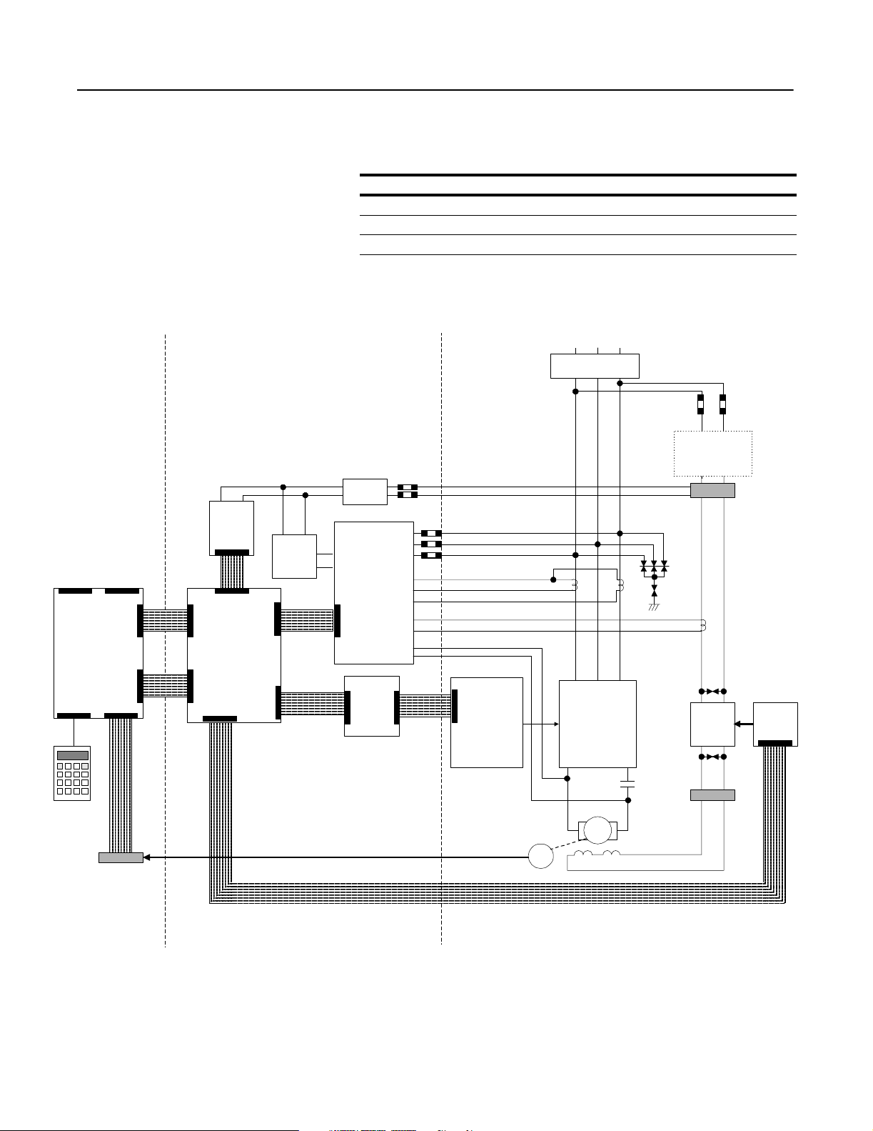
Hardware Overview The hardware components shown in form the high-horsepower 1395
DC drive. These drive components can be broken down into the
following three categor ies:
Hardware Description
Control Controls the drive system and interfaces with external devices
Control/Power Interface Interfaces the control components with the power components
Power Converts AC input to a DC supply for the motor
Figure 1.1
Drive Components
3-Phase AC Power
Circuit Breaker
Field Transformer
(Only Used For AC Inputs of
575 and 660 V AC)
J7 J6
Main Control Board
J4 J1
Programming
Terminal
DHT/DMT
TB3
Control
Transformer
Unit
Power Supply
J1
J7
J5
J8
24V DC
Feedback
Power Supply
J2
Feedback Board
J40
Power Stage
Fuses
AC Line Voltage Feedback
Armature Current Feedback
Field Current Feedback
Armature DC Voltage Feedback
Interface Board
J2
J9
J6
J3A
J3D
-
Gate
Interface
Board
Armature
Pulse
Transformer
Boards
Encoder Feedback
Encoder
3-Phase
SCR Armature
Bridge
-
Motor
Armature
F1 F2 F3 F4
+
M1
A1A2
MOVs
TB8
Single-Phase
SCR Field
Bridge
TB7
Field PT &
Snubber
J1
CONTROL CONTROL/POWER INTERFACE POWER
Publication 2361-5.01 July 1998
Page 16
1-4 Product Overview
Control Boards The control boards mana ge and control the system, processing status
information from syste m components a nd commanding drive
components and activit ies .
Figure 1.2
Control Boards
Main Control Board Adapter Boards
CH1
FCT
F14 F 15
Feedback Board
Main C ontrol
Board
Feedback Board
Main Control Board
(behind adapter boards)
Discrete or
Digital
Reference
Adapter Board
(Port A )
O
PTIONAL
Communication
Adapter Board
(Port B )
O
PTIONAL
MP
24V DC Supply
Publication 2361-5.01 July 1998
Page 17
Product Overview 1-5
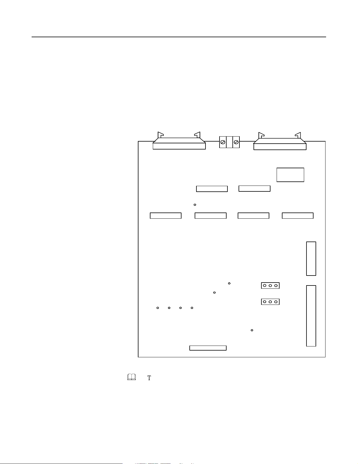
Main Control Board
The main control board is the center of the control pr ocessing. This
board has a number of test points and jumpers that are us ed during
startup and troubleshooting. Refer to the troubleshooting manua l for
more information on test point s and jumpers.
Figure 1.3
Main Control Board
J2 J4 J5
Connection
To
Encoder
TP42
TP50
Connection to Power
Stag e Interface Board
TP2 TP5
TP13
TP12
TP11
TP15
TP23
TP32
TP35
VP
1 2 3
1 2 3
1 2 3
J10
J9
J8
Connection to
Programm ing Terminal
TP9 TP6
TP24
TP8 TP3 9TP17
TP25
TP33
TP21
TP34
TP43
TP1
Connection to Power
Stage Interface Board
TP27 TP26
TP31 TP29
TP30TP38
CP
TP28
TP41
TP20
TP19
TP10
J7
Port A
(To Adapter Board)
SP
TP45
TP46
J6
TP47
TP44
TP20
TP49
1
2
3
TP54
ISO+12V
TP52
TP56
TP51
DGND
-12V
+5V
Port B
(To Adapter Board)
TP58
J14
TP55
+12V
TP53
IGN D
TP58
ISO +5 V
TP57
AGND
Publication 2361-5.01 July 1998
Page 18

1-6 Product Overview
Door-Mounted Programming Terminal
The door-mounted Bul letin 1300 programming terminal is the
interface m odule used to program and control the drive (typically
used in standalone applic ations). This terminal has an LCD screen
and a 24-key environment-sa fe keyp ad.
Adapter Boards
Optional adapter boards (such as the discrete a dapter board, digital
reference adapter board, node adapter board, and multicommunication adapter boa rd) connect the drive to networks and
provide I/O capabili ties.
&
Adapter board and programming terminal publications are listed in
the preface o f this manual. Please refer to the appropriate manuals for
more information.
Publication 2361-5.01 July 1998
Page 19
Product Overview 1-7
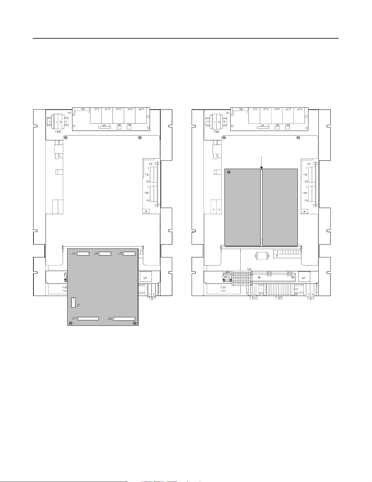
Control/Power Interface Boards Control/power interface boards are used to provide a link between
control boards (which are responsible for managing the drive), and
power components ( which ar e clos ely assoc iated wit h the actua l drive
hardware and operations).
The following items are used to provide this interfacing:
• power stage int erfa ce b o ard
• unit power supply board
• feedback board
These items a re located on the control module in the disconnect bay
of the drive, and are arranged as shown below. Accessibility to the
power stage interface board and the unit powe r supply is gained by
lowering the front panel.
Figure 1.4
Control/Power Interface Boards
Feedback Board
Alternate Field Bridge
Configuration
Field Pulse Transformer
and Snubber Board
CH1
43A Field
FCT
F16
F14
F15
F4
F20
F21
J9
Bridge
FAN 4
24V DC Supply
12345 789
MP
TB1
Power Stage
Interface Board
2MOV
3MOV
Gate Interface
Board
10
CH1
Option 14FX
Field Bridge
FCT
FAN 4
2MOV
3MOV
Unit Power Supply
Board
Publication 2361-5.01 July 1998
Page 20
1-8 Product Overview
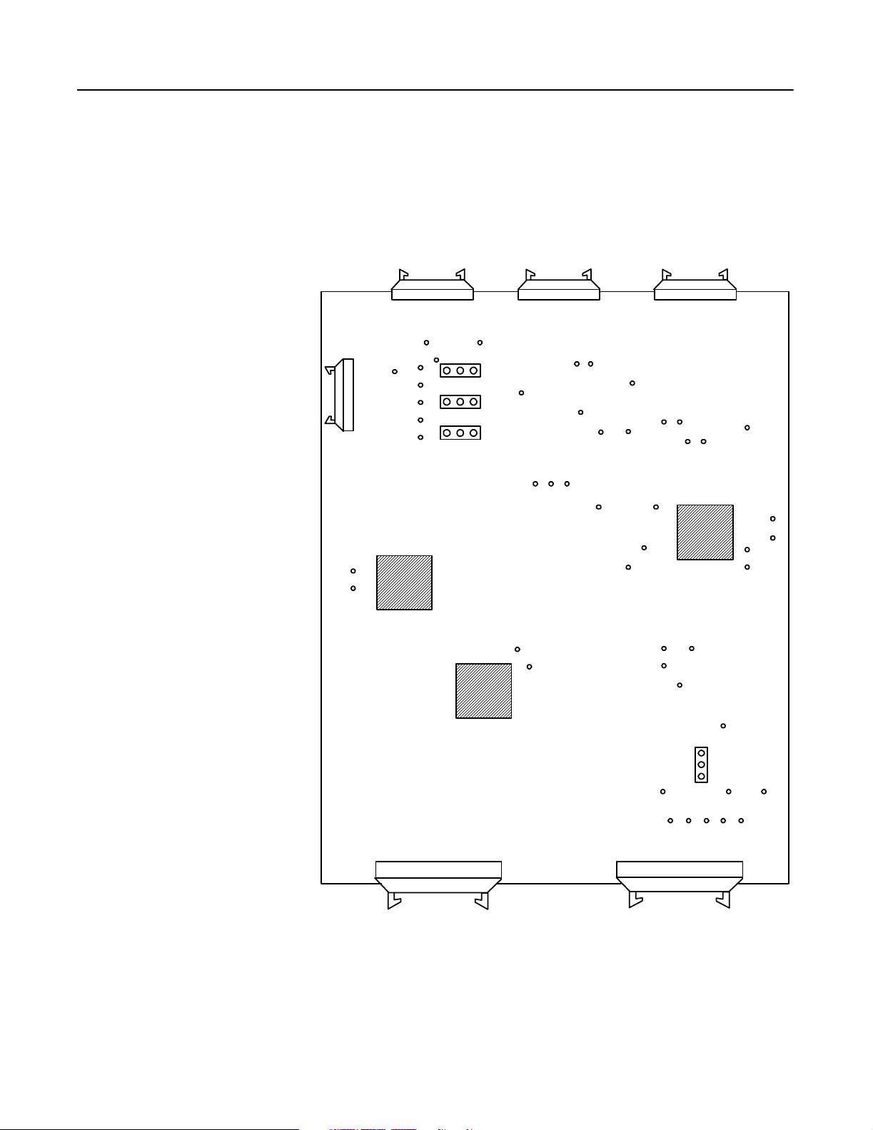
Power Stage Interface Board
The power stage int erface boar d is used as the c hief interfac e between
the main control board and other boards of the system. This board is
responsible f or distributing power and control signals to and from the
main control board, gate interface board, field-pulse transform er
board, feedback board, and unit power supply. Refer to Figure 1.1 to
see how this board is connected in the drive.
Figure 1.5
Power Stage Interface Board
Connection to Unit Power
Supply and TE
J8 J9
Connection to M ain Control Board Connection to M ain Control Board
Connection to
Field Transformer
TP1
(+24V)
J3D
TP8
TP7
TP6
TP5
(-12V)
(Gnd )
(+12V)
(+5V)
TB1
J2J6
Connection to
Feedback Board
J3C J3B J3A
Connections to
Gate Interface Board
Connection to
Main Cont actor , Pilot Re lay,
and Unit Power Supply
TP2
TP3
J1
J11
J12
Publication 2361-5.01 July 1998
&
J7
Connection to
Un it Pow er S upp ly
TP9
Connected to T B3
(Standard Interface)
J10
The test points and jumpers shown in the diagra m are used for startup
and troubleshooting pr ocedures. Refer to the troubles hooti ng manual
for more information on test poin ts and jumpers.
Page 21
Product Overview 1-9
The power stage interface boa rd provide s the following services
between the main control board and othe r boar ds in the system:
• furnishes DC control power to the main cont ro l board (from the
unit power supply)
• provides 3-phas e li ne synchronization signals to the main c ontrol
board
• accepts signals from the main cont r ol board and produces the
logic and drivers for armature and f ield-pulse transformers
• accepts signals f or start/stop logic, protection I/O, and drivers for
operating the main DC contactor
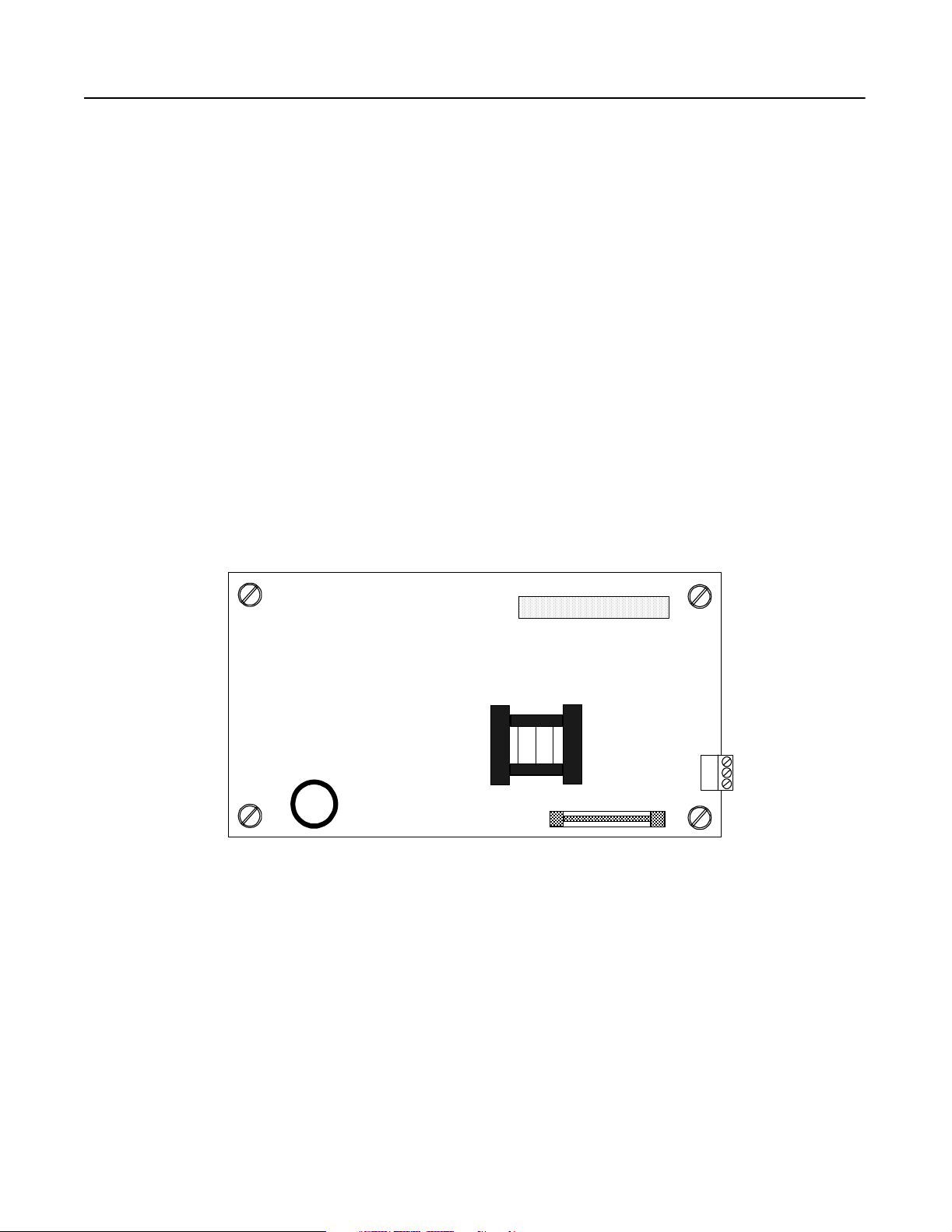
Unit Power Supply Board
The unit power supply board convert s 115V AC input into regulated
+5V DC and ±12V DC control voltages. These control vol tages are
routed through the power stage interfa ce board to provide power to all
the printed circuit boards.
Figure 1.6
Unit Power Supply Board
Connection to Power
Stage Interface Board
(+5V and ±12V)
F1
J1
Connection to Power
1
Stage Interface Board
2
3
(115V AC)
Publication 2361-5.01 July 1998
Page 22
1-10 Product Overview
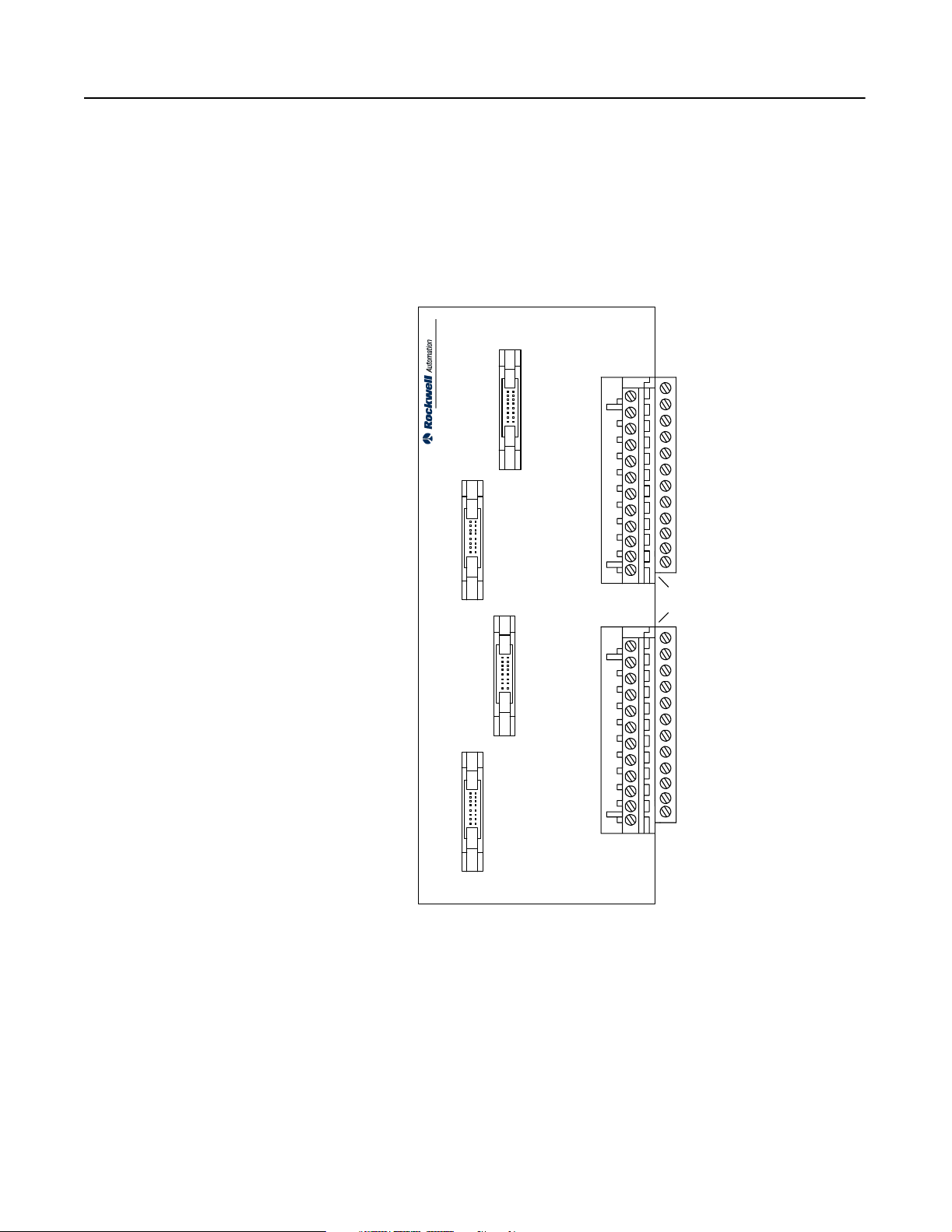
Feedback Board
The feedback board receives sta tus information from the drive
components, scales it to a signal le vel, and supplies it to the main
control board (through the power stage interface board).
Figure 1.7
Feedback Board
TB1
(1) (2) (3) (4)
Jumper Connection
(Field Current)
150 VAC
TO
300 VAC
AB
576VAC
690VAC
150 VAC
TO
TO
300 VAC
TO
575VAC
690VAC
TO
301VAC
TO
575VAC
576VAC
301VAC
J40
To Pow er Stage
Interface Board
The feedback board has terminals f or the 3-phase AC inputs (A, B,
and C) and for the armature power (VA+ and VA-), a series of jumper
connections to adjust for AC input voltage, jumper connections for
the field current, a bus connection to the power stage interface board,
two terminals blocks for placing burden resistors in parallel to the
circuit, and a Phoenix connection terminal block connect ed to other
drive components.
Note: Jumper settings are defined in the installation chapter of
this manual.
150 VAC
TO
300 VAC
301VAC
TO
575VAC
576VAC
TO
690VAC
C
150 VAC
TO
300 VAC
301VAC
TO
575VAC
VA+
576VAC
690VAC
TO
TB2 TB3
FEEDBACK BURDEN RESISTOR FEEDBACK BURDEN RESISTO R ARMATURE
Not Used
150 VAC
TO
300 VAC
301VAC
TO
575VAC
576VAC
690VAC
VA-
TO
Jumper Connections
(AC In put Voltage )
Publication 2361-5.01 July 1998
24V DC Power Supply
There are three 24V DC power supply units that may be install ed in
the drive. There is a feedback board supply, an optional air flow
sensor supply, and an optional cont rol board supply (us ed to powe r an
optional adapter board) . These supply units are fed from the 1 15V
AC control power circuit.
Page 23
Product Overview 1-11
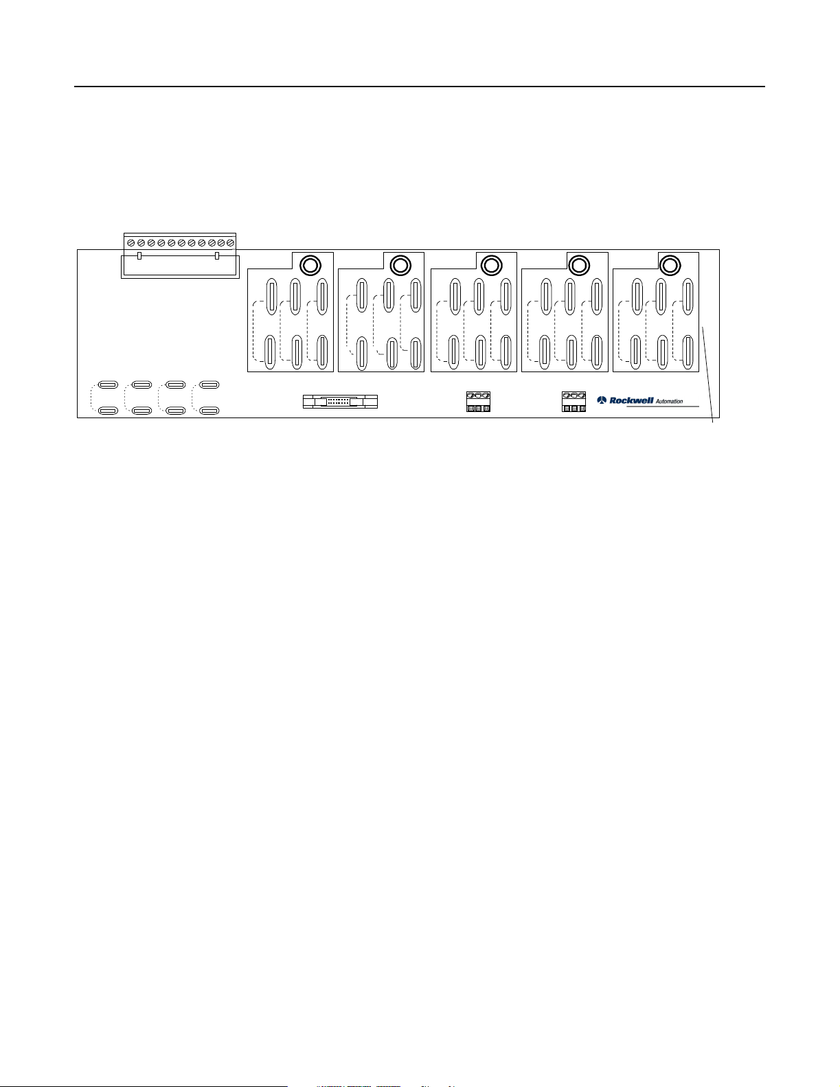
Gate Interface Board
The gate interface board is the junction between the power stage
interface boar d and the individua l armature-puls e transformer boards.
This board ha s four bus connections to the power stage interface
board and four Phoenix terminal bloc ks distributing signals to the
armature-pulse transformer boards.
Figure 1.8
Gate Interface Board
Connections to Power Stage
Interface Board
TB1
J4
J3
Co nnections to Arm ature-Pulse
Transformer Boards
J2
J1
TB2
Publication 2361-5.01 July 1998
Page 24

1-12 Product Overview
Power Components This section will break down and define the incoming power,
armature power, and field supply components.
Incoming Power Components
Incoming Devices
The 1250 and 1650A DC drives a re intended to be used straight from
the customer- supplied, power controlled incoming lines, without any
additional isolation transformer or line chokes (however, adding
either of these would increa se isolation to other equipment on the
power lines).
The 3000A DC drive does not require an isolation transformer or line
reactors if it is the only eq uipment on the power lines. However, if it
shares power with ot her equipm ent on th e same power lines, it will be
necessary to use eithe r line reactors or an isolation transformer ahead
of the drive.
The system designer needs to provide proper circuit impedence to
limit the sho rt circui t c urrents according t o the break er derat ing cha rts
given in Appendix A.
Some drives may require an output inductor in serie s with the
armature, especially for older machines which do not have enough
internal inductance for a proper armature commutation process.
AC Input Busbars
Tin plated busbars are supplied for all input connections through the
top of the disconnect bay. Busbar dimension dia grams are given in
Appendix A.
Main Disconnect (Optional)
A 3-phase circuit breaker can be supplied on the incoming line for
each high-horsepower drive. Appendix A lists circuit breaker
specifications, and shows diagrams of the circuit breakers settings for
the 1250, 1650, and 3000A DC drives.
AC Line Fuses (Optional)
AC line fuses can be supplied for the 3-phase incoming power.
Note: Units require either a main disconnect or AC line fuses.
Publication 2361-5.01 July 1998
Page 25

Product Overview 1-13
Control and Field Power
The first (L1) an d thir d (L3 ) pha s e of the inco m ing p ow er are t app ed
off and fused to provide single-phase AC power to the primary of
control power t ransformer (115V AC), field supply circuit (460V AC
maximum), and 24V DC power supply.
Note: For drives using a 575 or 660V AC input, a step-down
transformer will be required for the field supply circuit (see
Figur e 1. 12).
AC Line RC Suppressor (Optional)
The optional AC line RC suppressor is a device used for limiting line
voltage spikes in drives when the medium volta ge source to the
primary of the distribution transformer is switched. The option is
offered for a dist ri bution transformer primary voltage of 2300V or
greater.
Publication 2361-5.01 July 1998
Page 26
1-14 Product Overview
Armature Power Components
The armature power components work together to convert the 3phase AC input to a DC output used for powering your motor
armature.
The following items make up the armature power circuitry:
• armature bridge (and its subordinate components)
• cell fuses
• gate board s
• DC contactor
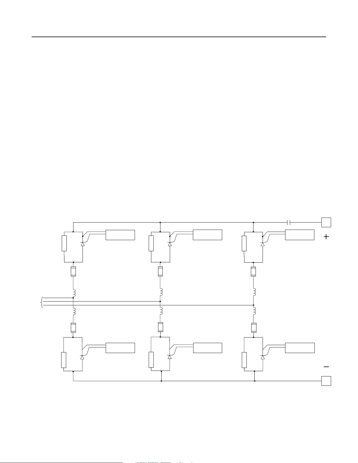
Armature Bridge
The armature bridge is design ed to convert incoming AC power to
DC power. The non-regenerative bridge is shown in Figure 1.9. Cell
fuses protect the thyristors in the event of a bridge failure.
Figure 1.9
Armature Bridge (Non-Regenerative)
3-Phase
AC
Input
Main
Contactor
SNUBBER
Armature-Pulse
Transformer Board
SNUBBER
Armature-Pulse
Transformer Board
SNUBBER
Armature-Pulse
Transformer Board
A1
Armature
Voltage
Armature-Pulse
SNUBBER
Transformer Board
SNUBBER
Armature-Pulse
Transformer Board
SNUBBER
Armature-Pulse
Transformer Board
A2
Publication 2361-5.01 July 1998
Page 27
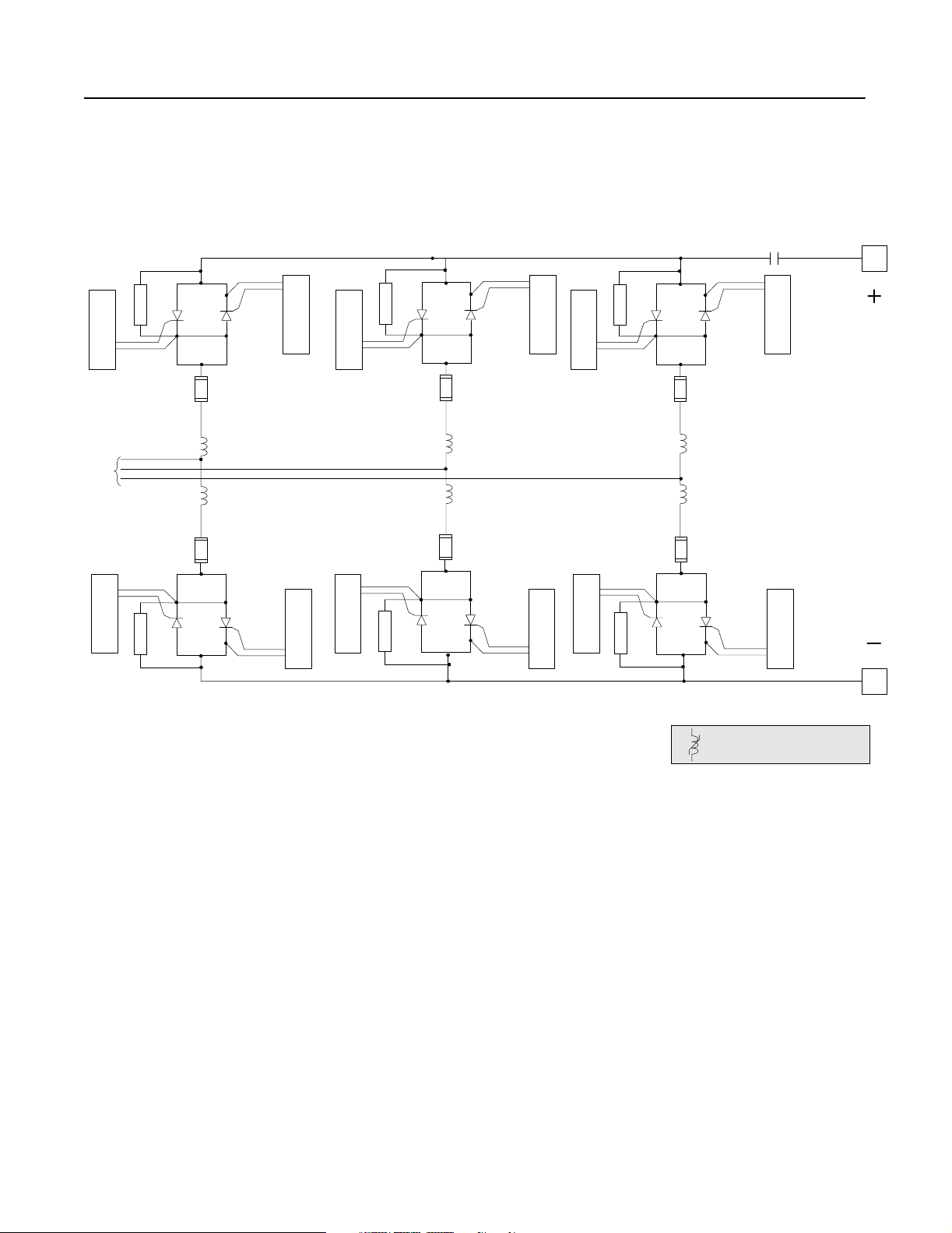
Product Overview 1-15
The regenerative bridge , shown in Figure 1.10, allows the bridge to
regenerate, or to di rect p owe r ba ck wards onto the inco ming lines.
Figure 1.10
Armature Bridge (Regenerative)
Main
Contactor
Armature-Pulse
3-Phase
AC
Input
Transformer Board
SNUBBER
Transformer Board
Armature-Pul se
SNUBBER
Armature-Pulse
Transformer Board
Transformer Board
Armature-Pul se
SNUBBER
Armature-Pulse
Transformer Board
Transformer Board
Armature-Pul se
A1
Armature
Voltage
Transformer Board
Armature-Pulse
Armature-Pulse
Transformer Board
SNUBBER
Armature-Pulse
Transformer Board
SNUBBER
Transformer Board
Armature-Pulse
Armature-Pulse
Transformer Board
SNUBBER
Transformer Board
Armature-Pulse
A2
The 3000A unit uses solid core (ferrite)
chokes on the AC line.
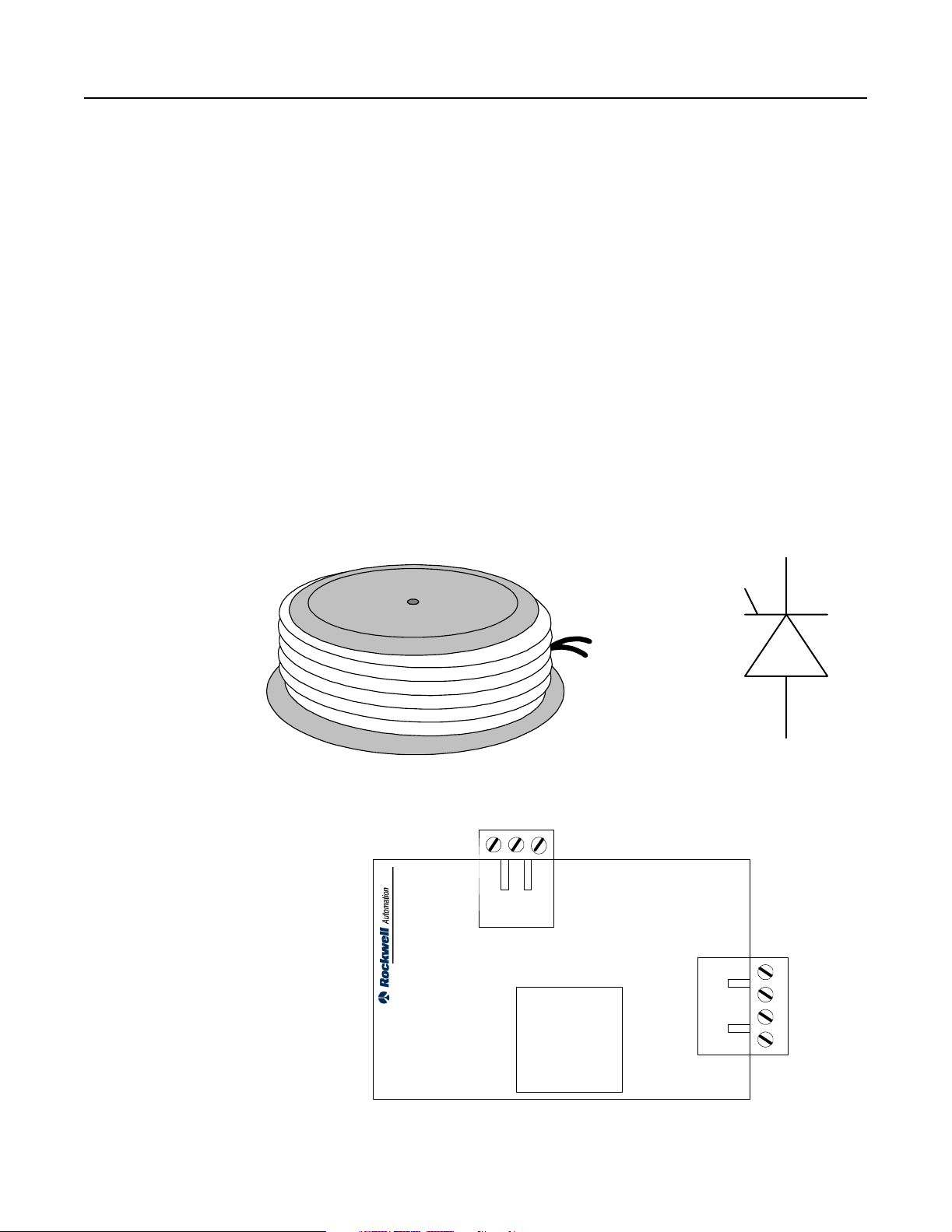
Silicon-Controlled Rectifiers (SCRs)
Each drive uses silicon-c ontrolled rectifiers (SCRs) in the thyristor
bridge to switch the incoming 3-phase AC power to DC output
power.
These SCRs allow current to flow from anode to cathode when two
conditions are met. First, like a diode, it must be forward biased.
Second, an appropriate pulse must be applied to the gate (through the
pulse transformer board).
The current will continue thr ough the SCR until the voltage across it
reverses and the current drops to zero (called line commutation).
Figure 1.11 shows a picture of an SCR, depicting its polarity.
Publication 2361-5.01 July 1998
Page 28
1-16 Product Overview
Silicon-Co ntrolled Rectifier
(SCR )
Snubbers
Snubbers (resistor/capacitor assemblies) are installed in para llel with
the SCRs, working with the cell reactors to provide adequate voltag e
suppression when the SCRs switch off.
Armatur e-Pulse Transformer Boards
Armature-pulse transformer boards provide the appropriate gate
voltage and current to trigger an SC R. In addition, these boards
provide gate driver isolation from the control logic. Figure 1.11
shows an armature-pulse tr ans former board.
DC Contactor
The main DC contactor is used to break the DC current to the motor
armature. Coil voltage to the con tacto r is controll ed by contacts from
the pilot relay.
Figure 1.11
Armature Bridge Hardware
Armature-Pulse Transformer
Board
Anode
Cathode
J2
Gate
Leads
Gate
Anode
Cathode
Publication 2361-5.01 July 1998
J1
Page 29
Product Overview 1-17
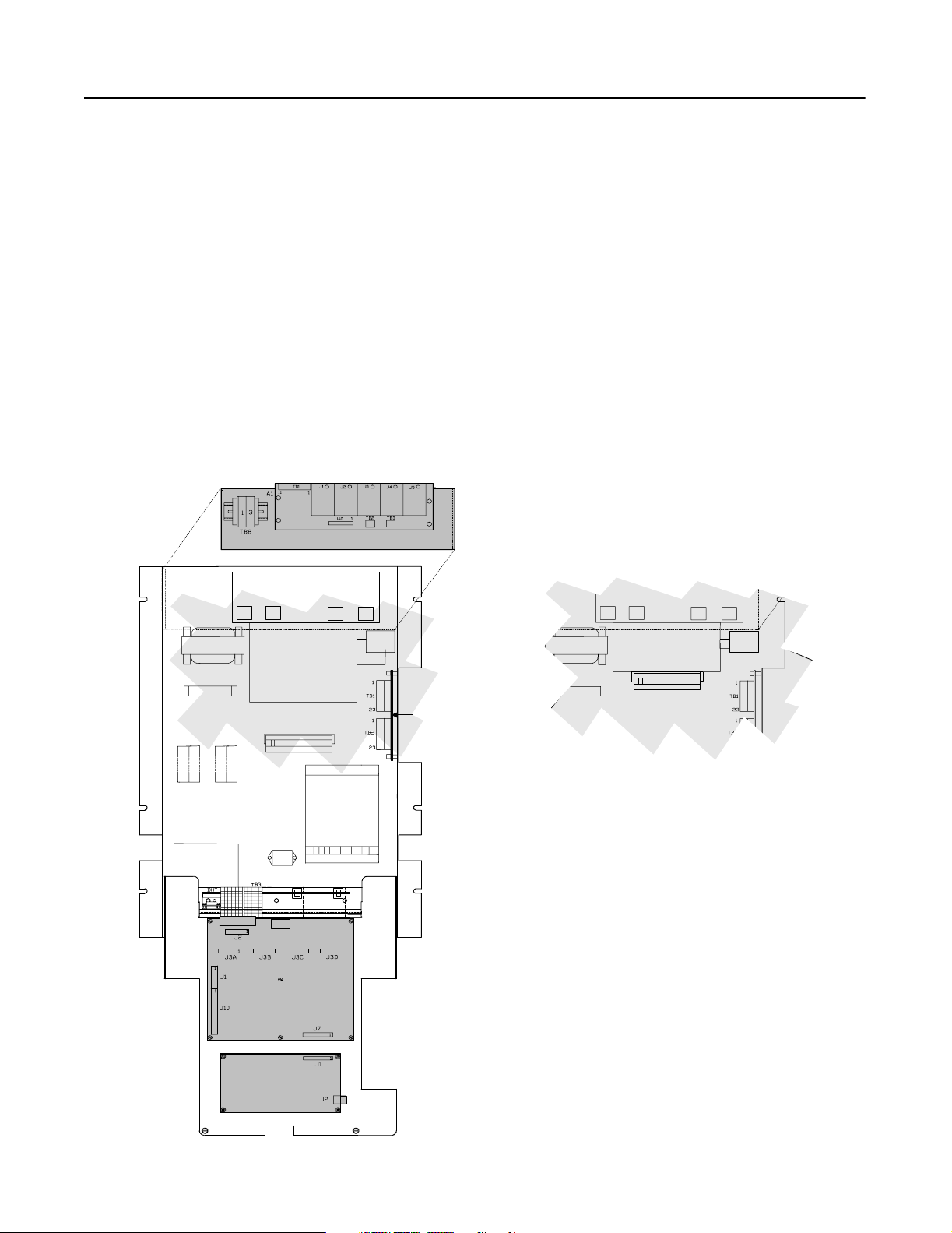
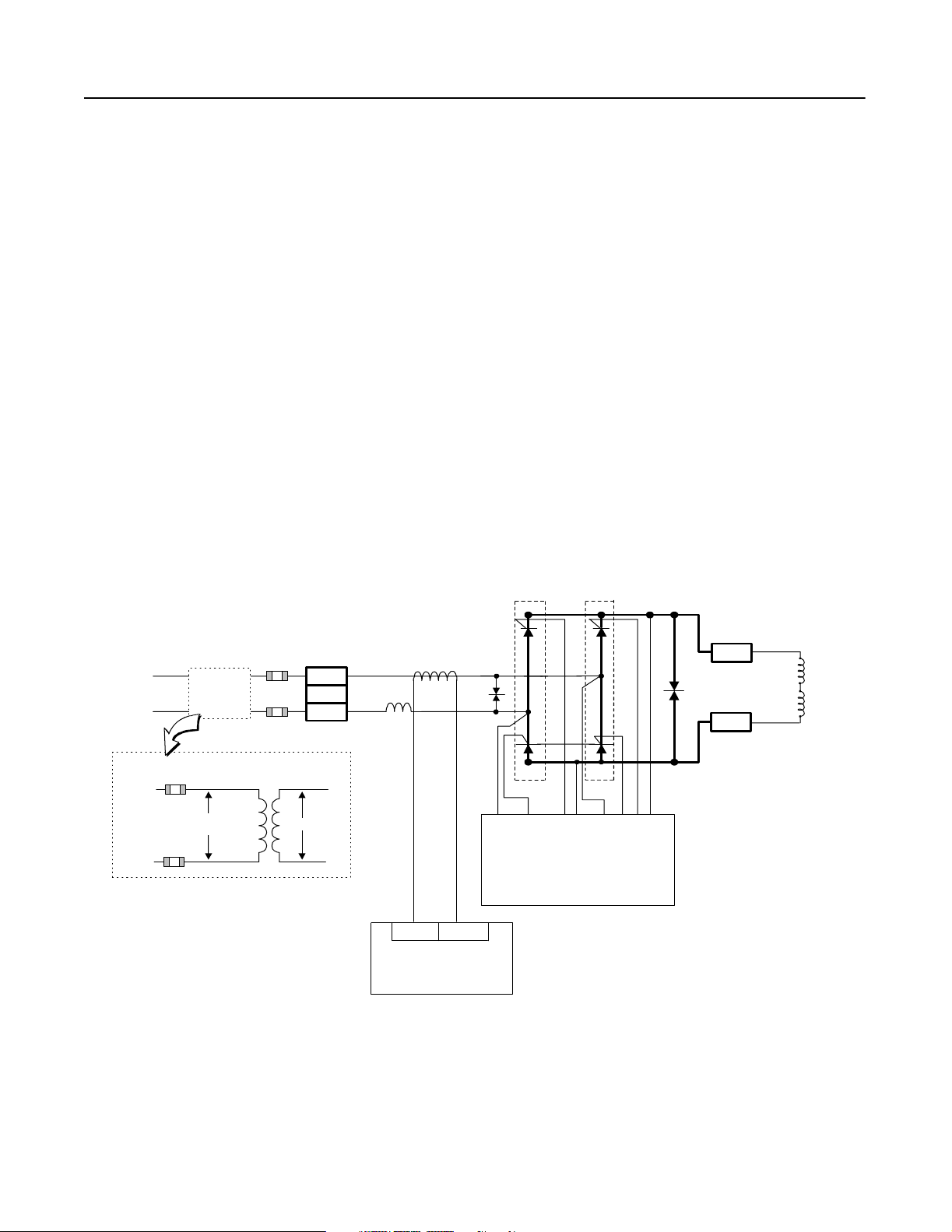
Field Power Components
The field power components work together to convert single-phase
AC power to a DC output used for powering your motor field.
The following items make up the field power circuitry:
• field bridge
• field-pulse tra nsformer board
In addition, fuses, meta l- oxide varistors (MOVs), and an induc tor, as
shown in Figure 1.12, are used to pr otect the field bridge from
extreme curre nt and voltage conditions. The field circuitry is fancooled.
Note: The field power components are rated for voltages up to
460V AC. Drives with input voltages of 575 or 660V AC use a
single-phase fie ld transformer (PT5) to step down the voltage to
460V AC. PT5, shown in Figure 1.12, is connected at the
customer site.
Figure 1.12
Field Bridge
1L1
Field Step-
Downl
Transformer
1L3
Typical Transformer Arrangement
(used for 576 or 660V AC inputs)
1L1
1L3
575 or
660V
(PT5)
H1H2X1
PM1
TB8
1
2
3
460V
X2
FCT
CH1
8
TB1
Feedback Board (A1)
3MOV
Field-Pulse Transformer Board (A5)
9
PM2
G11 F2 L1L3 G12
G21 G22 F1
2MOV
TB7
F +
1
3
F
1
F
2
F
3
F
F -
4
Publication 2361-5.01 July 1998
Page 30

1-18 Product Overview
Standard
Field Bridge
The field bridge uses four SCRs to convert the single-phase AC
power into a DC output. For the SCRs to conduct, they must be
forward biase d and have a pulse applied to the ir gates. The SCR gate
is enabled by the field-pulse tr ansformer board.
Field-Pulse Transformer Board
The field-pulse tranformer board provides the necessary gate volta ge
and current to trigger the SCRs on. This board uses a resistor/
capacitor arrange ment to protect the SCRs from rapid voltage
changes.
Figure 1.13
Field-Pulse Transformer Boards
Connection to Power Stage
Interface (SCR Gate Pulses)
T1
C2
L3
R3
L1
R4
J1
C3
Option 14FX
T3
G11
G12
Connection to SCRs
in PM1 of Field Bridge
F1
D7
F2
G22G21
R13
D8
Connection to SCRs
in PM2 of Field
Connection to Power Stage
Interface (SCR Gate Pulses)
T3
C2
T1
R3
J1
R4
R13
D8
C3
R11
D7
R5
T4
T2
Publication 2361-5.01 July 1998
G11
G12
Connection to SCRs
in PM1 of Field Bridge
F1 F2 L3 L1
G21
G22
Connection to SCRs
in PM2 of Field
Page 31

Chapter
2
Input Voltage (V AC) Nominal Output HP
460 700-750
575 750-900
660 750-1000
Your 1250A DC Drive
Contents This chapter is designed to help you unde rs tand the construction of
your 1250A Bulletin 1395 DC drive. The following topic s will be
covered in this chapter:
Topic Pa ge
Introduction 2-1
Drive Layout 2-2
Drive Schematics 2-3
Symbol Reference Chart 2-6
Drive Structure 2-8
Conclusion 2-8
Introduction Your 1250A DC drive functions with the following features:
• The 1250A drive uses twelve SCRs (regenerative) or six SCRs
(non-regenerative) in the armature bridge to convert the 3-phase
AC input to a DC output. The SCRs are built into a heatsink
assembly and are cooled by the bridge fan.
• The 1250A drive is protected from incoming fault curr ents with a
circuit bre aker. The components of your drive (the armature
bridge, field bridge, and control components) are protected with
fuses, MOVs, snubbers, and/or chokes.
• The 1250A drive is cons tructed and housed in thr ee bays, the f irst
bay containing the AC input and control hardwa re, the second
bay containing the armature bri dge hardware, and the third bay
containing the DC output hardware.
• The 1250A drive has an optional top-hat extension available for
the AC input bay.
• The 1250A drive can be built with an optional through bus
assembly, allowing the 1250A drive and other connected drives
to tap off from the same AC input.
Publication 2361-5.01 July 1998
Page 32

2-2 Your 1250A DC Drive
Drive Layout Figure 2.1
1250A DC Drive Layout
F51 F52 F53
ACT1 ACT3
L1 L2 L3
SP1
SP2
SP3
SP4
F31,
F32, F33
TB1
TB8
CB11
or
J1 J2 J3
J40
EA4
TB2
PP1 PP2
A14R
A11F
S1 S2
F12 F12A F11 F11A
F1, F2,
F3
J4
J5
TB3
F9 F9A F8 F8A
A16R
A13F
PP3
A12R
A15F
S3
F10 F10A
F7 F7A
D1
M1
R1
MP
F17,
F18,
F19
M11
DHT
F20, F 21
1395 Regulator
Control Boards
TB3
TB10
PT2
TB5 TB7
A14F
A11R
TB2 TB1
PP4 PP5 PP6
TB1FAN
SP
FAN1
A16F
A13R
A12F
A15R
A2(-)
Disconnect Bay Bridge Bay Contactor Bay
A1(+)
Publication 2361-5.01 July 1998
Page 33

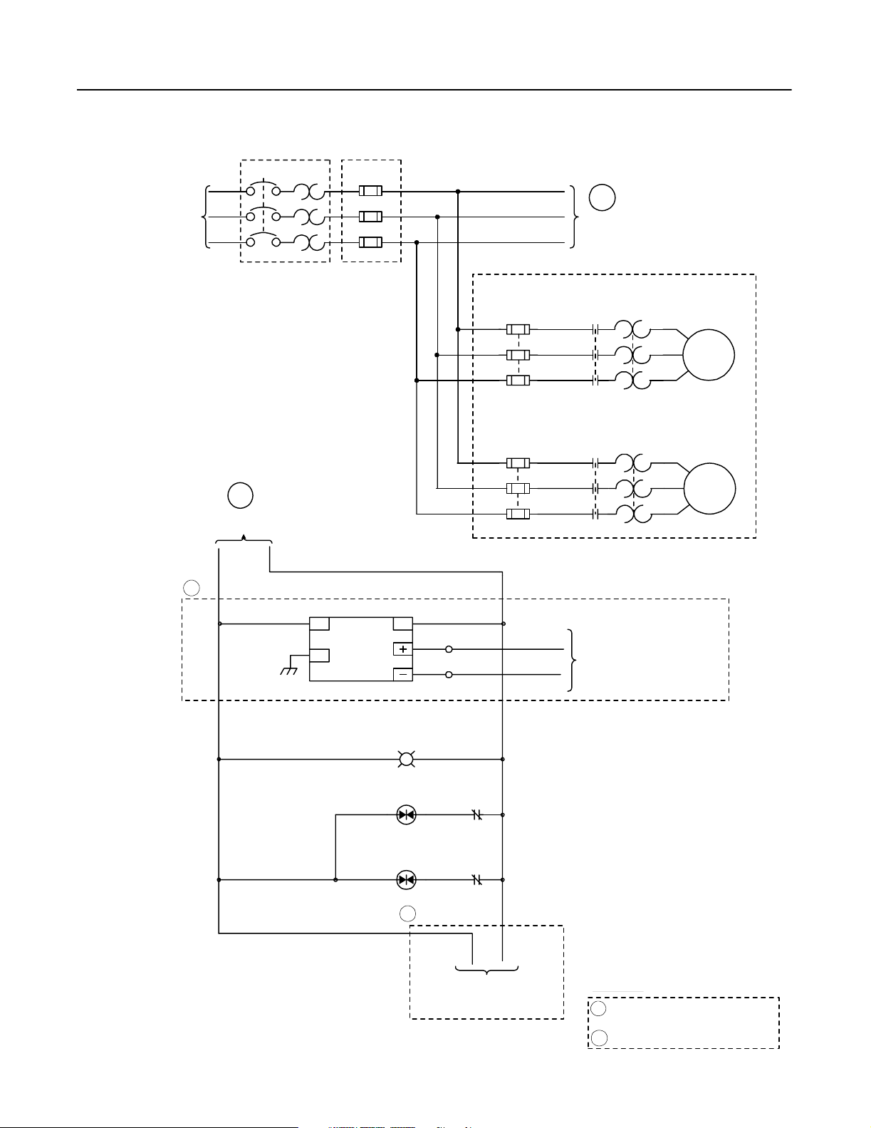
Drive Schematics Figure 2.2
1250A DC Drive Electrical Schematic, Sheet 1
Your 1250A DC Drive 2-3
3-Phase
AC Input
CB11
L1
L2
L3
Circuit Breaker
B
Co ntin ued in
Figure 2.3
Option
F51
F52
F53
Line Fuse
Option
1L1
1L2
1L3
F17
F18
F19
A
Co ntin ued in
Figure 2.3
OL11
M11
DC MOTOR
AC BLOWER
MOTOR
(T1)
(T2)
(T3)
1
PS1
ACL
FG
24VDC
161689
0.5A
ACN
TB230HI
TB120LO
PL1
M11
OL11
2
To 115V AC Discrete Adapter Board
To 24V DC Discrete Adapter Board
or 24V DC Digital Reference Board
FOOTNOTES :
Par t of 2 4V DC D isc rete Ad apter Op tion
1
or 24V DC Digital Referenc e Option
2
Part of 115VAC Discete Adapter Option
Publication 2361-5.01 July 1998
Page 34

2-4 Your 1250A DC Drive
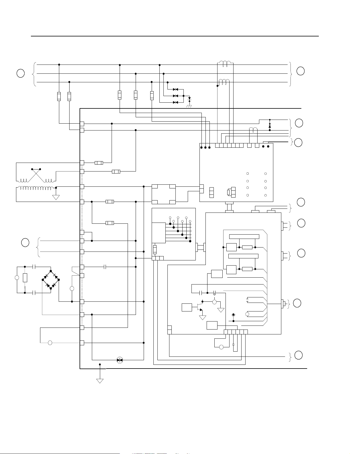
Figure 2.3
1250A DC Drive Schematic, Sheet 2
A
Continued
fro m Fig ure
2.2
(X1 )
Continued
Figure 2.2
M1
(H3) (H2)
(H1 )
B
fro m
MP
R1
1K
25W
MP
120V
1L3
1L1
1L2
(H4)
FAN 1
ACT-1
E
ACT-3
F21
F20
TB8
1
2
TB5 F14
1
2
PT2
MP
12
GND
STUD
F16
F4
PR
3
5
4
15
9
10
14
6
11
13
(X2)
PE
D1
F1
L1A
F15
FAN 4
F2
L3A
F3
AC2 +
PWR SUPPLY
+12
-12
+5
COM
+ 12 IS O
+12 ICOM
1 2 5
SP3
SP2
SP1 SP4
(A9)
24VDC
(137825)
-AC1
UNIT PWR SU PPLY (A6)
TP1 TP2
TP3
TP6
F1
J2
TB1
1
(TE)
2
TP4
1395
LOGIC
TP5
3MOV
FCT
11 6
5 10 7 1 2 9 8
A B C
FEEDBACK PCB
(A1)
FDBK
RES.
J40
J2
POWER STAGE
INTERFAC E PCB (A7)
1395
LOGIC
1395
LOGIC
1395
TE
J1
1 2 3
TB3
FDBK
B URD EN
RES.
ARM.
115V 24V
O1 O2 O3
115V 24V
O1 O2 O3
ESR-COAST
DRIVE
READY
K 2
TP5
24VDC
E SR
24V COMM 12
4 5 6
M1
TB2
4
3
B URD EN
J1
E-COAST
K2
+24 V
TE
J7
LOGIC
K3
SYST EM
TRIP
1395
LOGIC
P R
PILOT RELAY
FIELD RANGE
(43A Field)
J44
J43
J42
J41
J3A-J3D
R
R
115V HI
115V LO
K1
24V+ 11
J11
MOTOR
TEMP.
J12
RESET
4
5
6
7
8
9
10
VA+ V A-
J39
J38
J37
J36
J6
1
2
3
J10
Continued on
Next Page
G
Continued on
Next Page
A1
A2
H
Continued on
Next Page
J
Continued on
Next Page
J9
J8
K
Continued on
Next Page
L
Continued on
Next Page
M
Continued on
Next Page
N
Continued on
Next Page
Publication 2361-5.01 July 1998
PE
Page 35

E
Continued fr om
Previous Page
SNUBBER
4R
1F
F12A
F12B
CH11
CH14
F9A F9B
SNUBBER
1R
4F
SNUBBER
6R
F11A
F8A
SNUBBER
3R
SNUBBER
2R
3F
F10A
F11B
CH12 CH13
CH15 CH16
F8B
F7A F7B
SNUBBER
5R
6F
5F
F10B
2F
M1
Your 1250A DC Drive 2-5
H
Continued from
Previous Page
+
A1
DC MOT OR
-
A2
(A2)
ARM
(A1)
G
Continued from
Previous Page
J
Continued from
Previous Page
K
Continued from
Previous Page
L
Continued from
Previous Page
Gate
Interface
PCB
S1 S2 S3
WHT
3
1
ARMATURE PULSE
TFMR
(12 TOTA L)
J1
4
J2
J5
RED
123
SYS
PROC
"SP"
J7 J6
MAIN
CONTROL
PCB(AB)
CURR
PROC
"CP"
PM 1 PM 2
L3
HEATSINK
G1
G2
L1
F2
FIELD PULSE
TFMR AND SNUBBER
PCB(A5)
(1 TOTAL)
J1
VEL
PROC
"VP"
J4
1024PPR
COMMON
V+ 12-15V
SIGNAL B
SIGNAL B
SIGNAL A
SIGNAL A
SHIELD
MOUNTE D
TERMINAL
SHUNT FIELD
DOOR
+
1
2 MOV
TB7
TB7
-
3
G2
G1
F1
+12 COM
+ 12 V
Z
A
A
J1
DHT
2S
TB3
13
14
15
16
Z
17
B
B
18
19
20
TE
1024PPR
COMMON
V+ 12-15V
SIGNAL B
SIGNAL B
SIGNAL A
SIGNAL A
SHIELD
(F1 ) (F 2) (F3 ) (F 4)
Encode r
(Du al Out Ex am ple)
PROGRAMMING
M
Continued from
Previous Page
N
Continued fr om
Previous Page
TB10
1
2345
TE
P ORT " A" POR T ’B ’
6
+24V Out
-24V ECOAST
+24V ECOAST
Ready 2
Ready 1
115V Common Out
115V ECOAST2
115V ECOAST1
Reset In
Motor Temp In
Common In
TB3
12
11
10
9
8
7
6
5
4
3
2
1
24V DC
ECOAST
Drive Ready Output
115V AC Common
115V AC ECOA ST
Reset
Mo tor Therm ostat
No te: Mo re co nfig uratio n d eta ils for T B3 ar e gi ven in the
installation chapter of publication 1395-5.40.
24V DC or 115V AC
Voltage Source
Publication 2361-5.01 July 1998
Page 36

2-6 Your 1250A DC Drive
Symbol Reference Chart
Table 2.A: 1250A DC Drive Symbol-to-Component Reference
Symbol Description Option 460V AC 575V AC 660V AC
(A1.RES) A1 PCB feedback scaling resistor 3.65 ohm, 2 W, 1%
2 - 3MOV Field suppressors
A1 Feedback PCB
A11F-A16F Armature pulse transformer PCB
A11R-A16R Armature pulse transformer PCB
A3 Gate interface PCB
A5 Field pulse transformer PCB
A6 Unit power supply PCB
A7 Power stage interface PCB
A8 Main contr ol PCB
A9 Feedback PCB power supply
ACT1, 3 Line current transducer 2000:1
C1 Armature snubber capacitors 2µF, 2000V
CB11 Circuit breaker
CH1 Field choke
CH11 - 16 Cell chokes Air-core, 3.5uH, 1017A
D1 M1 bridge diode
DHT/DMT Configuration terminal
EA2 Tachometer adap ter scaling PCB
EA3 DHT/EHT configuration terminal
EA4 Line RC suppressor
EA5 Air flow sensor PCB
F1 - 3 Control branch / feedback PCB fuses 1A KTK 1A KTK 10A A70P
F14 - 15 PT2 control transformer primary fuses
F16 PT2 control transformer secondary fuses 5A KLDR
F17 - 19 Motor blower fuses 30A 3P (size 1) or 60A 3P (size 2)
F20 - 21 Field fusing for 460V AC configuration 45A, FRS
Field transformer primary fusing for 575V AC
configuration with 10kVA transformer
Field transformer primary fusing for 575V AC
configuration with 15kVA transformer
Field transformer primary fusing for 575V AC
configuration with 20kVA transformer
Field transformer primary fusing for 575V AC
configuration with 50kVA transformer
Field transformer primary fusing for 660V AC
configuration with 10kVA transformer
Field transformer primary fusing for 660V AC
configuration with 15kVA transformer
Field transformer primary fusing for 660V AC
configuration with 20kVA transformer
Field transformer primary fusing for 660V AC
configuration with 50kVA transformer
F31 - 33 Line RC snubber fuses
F4 Terminal block control power fuse 7A KLDR
F7 - 12, F7A - 12 A Armature bridge fu ses 630A, 1250V, 170M
F51 - 53 AC line fuses
FAN1-C1 Armature fan capacitor 25µF
FAN1 Armature bridge fan 2800CFM
FAN4 Field h eatsink fan 145 CFM
FCT Field current transducer 1000:1
J10 DHT/EHT configuration terminal D-shell
ä
1200A, N-frame
ä
ä
ä
ä
ä
ä
8A KLDR
25A, FRS
ä
30A, FRS
ä
45A, FRS
ä
100A, FRS
25A, 150X
ä
40A, 150X
ä
40A, 150X
ä
100A, 150X
ä
25A KTK 25A KTK 25A A70P
ä
1200A, KRPC
ä
Publication 2361-5.01 July 1998
Page 37

Your 1250A DC Drive 2-7
Symbol Description Option 460V AC 575V AC 660V AC
M1 DC armature contactor 1800A
M11 Motor blower starter 27A (size 1) / 45A (size 2)
MP Main p ilot for pilot relay
OL11, OL12 Motor blower overload
ä
PB1 Stop pushbutton
PB3 E-stop pushbutton
PB4 Jog forward pushbutton
PB5 Jog reverse pushbutton
PBL2 Start / running illuminated pushbutton
PBL6 Fault / clear faults illuminated pushbutton
Red EH,1NO/1NC
ä
Red MH P-P, 2NC
ä
Black FH, 1 NO/1NC
ä
Black FH, 1 NO/1NC
ä
Amber, 1NO/1NC
ä
Clear, 1N0/1NC
PE Power ground bus
ä
PL1 Power on pilot lig ht
Red, 115VAC XF-type
PM1 - 2 Field SCRs 90A, 1200V
PP1 - 6 Arm ature power poles
PR M1 contactor pilot relay
PS1 24V DC power supply 24V DC, 0.5A
ä
ä
24V DC, 0.5A
1.5 kVA
PS2 Air flow sensor p ower supply
PT2 Control transformer
PT5 Field transformer, 18A 10 kV A
Field tran sfor m er , 28A
Field tran sfor m er , 40A
Field tran sfor m er , 70A
ä
ä
ä
15 kVA
20 kVA
50 kVA
R1 M1, suppressor resistor 1k-ohm, 50 W
R1 - 2 Armature snubber resistors 40 ohm 240 W
R11 - 12 Multi-communication channels A & B terminal resistors 150 ohm, 2 W
ä
RH1 Speed potentiometer
5k-ohm, 2 W
S1 - 3 Heatsink thermoswitches 165°F
ä
S5 Air flow sensor
1000FPM
SCR SCR 1200A, 1800V
SCR-R SCR, (regeneration) 1200A, 1800V
SP PR suppressor
SP1 - 3 Line-to-line MOVs 460J, 320V AC 550J, 385V AC 600J, 420V AC
SP4 Y-to-ground 760J, 680V AC 760J, 680V AC 1050J, 750V AC
ä
SS3 Speed 1 - 2 - 3 selector switch
Std op, 2 NO/ 2 NC
TAS1 Motor thermoguard
TB1-FAN Bridge fan & capacitor terminal block
TB10 TE shield terminal block
TB3 Option PCB I/O terminal block
TB5 Branch power & 115 control terminal block
TB7 Field DC output terminal block
TB8 Field AC in put terminal block
TB11 O ptional miscellaneous control terminal block
TE Zero potential bus
Publication 2361-5.01 July 1998
Page 38

2-8 Your 1250A DC Drive
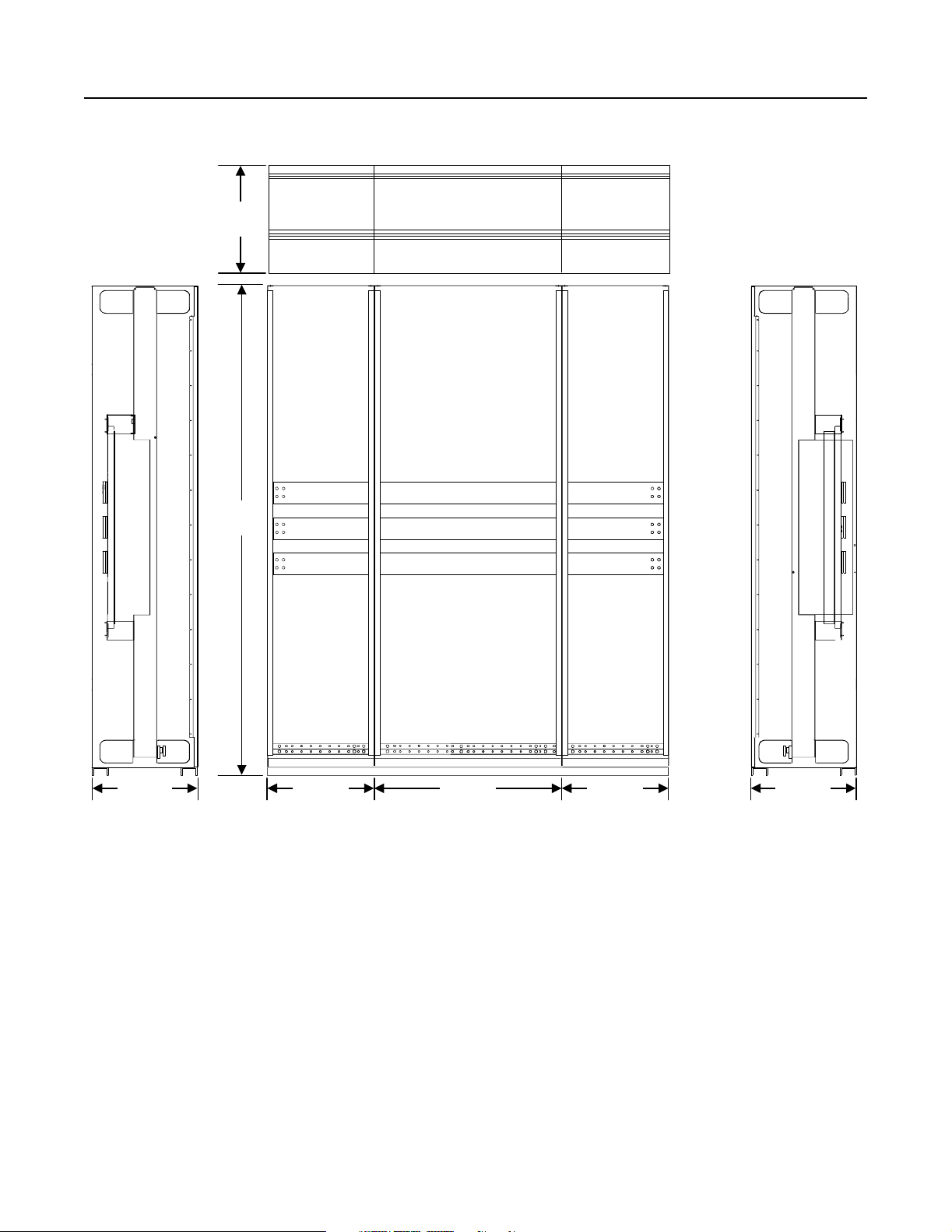
Drive Structure Figure 2.4
1250A DC Drive Structure
20 inches
(508 mm)
91.5 inches
(2324 mm)
20 inches
(508 mm)
20 inches
(508 mm)
35 inches
(889 mm)
20 inches
(508 mm)
20 inches
(508 mm)
Conclusion This chapter covered the components, sc hematics, and structure of
your 1250A DC drive. Unit specifications, derating charts, a power
dissipation chart, a circuit breaker illustration, an air baffle diagram,
and an input busbar diagram for the 1250A DC drive are all given in
Appendix A.
Publication 2361-5.01 July 1998
Page 39

Chapter
3
Input Voltage (V AC) Nominal Output HP
460 800-1000
575 1000-1250
660 1250
Your 1650A DC Drive
Contents This chapter is designed to help you unde rs tand the construction of
your 1650A Bulletin 1395 DC drive. The following topic s will be
covered in this chapter:
Topic Pa ge
Introduction 3-1
Drive Layout 3-2
Drive Schematics 3-3
Symbol Reference Chart 3-6
Drive Structure 3-8
Conclusion 3-8
Introduction Your 1650A DC drive functions with the following features:
• The 1650A drive uses twelve SCRs (regenerative) or six SCRs
(non-regenerative) in the armature bridge to convert the 3-phase
AC input to a DC output. The SCRs are built into a heatsink
assembly and are cooled by the bridge fan.
• The 1650A drive is protected from incoming fault curr ents with a
circuit breaker, and the DC output is protected from faul t currents
with a DC contactor. The components of your drive (the
armature bridge, field bridge, and control components) are
guarded with fuses, MOVs, snubbers, and/or chokes.
• The 1650A drive is cons tructed and housed in thr ee bays, the f irst
bay containing the AC input and control hardwa re, the second
bay containing the armature bri dge hardware, and the third bay
containing the DC output hardware.
• The 1650A drive has an optional top-hat extension available for
the AC input bay.
• The 1650A drive can be built with an optional through bus
assembly, allowing the 1650A drive and other connected drives
to tap off from the same AC input.
Publication 2361-5.01 July 1998
Page 40

3-2 Your 1650A DC Drive
Drive Layout Figure 3.1
1650A DC Drive Layout
F51 F52 F53
ACT1 ACT3
L1 L2 L3
SP1
SP2
SP3
SP4
F31,
F32, F33
TB1
TB8
CB11
or
J1 J2 J3
J40
EA4
TB2
PP1 PP2
A14R
A11F
S1 S2
F12 F12A F11 F11A F10
F1, F2,
F3
J4
J5
TB3
F9 F9A F 8 F8A F 7 F7A
A16R
A13F
PP3
A12R
A15F
S3
F10A
D1
MP
R1
M1
F17,
F18,
F19
M11
F27,
F28,
F29
M12
DHT
F20, F 21
1395 Regulator
Control Boards
TB3
TB10
PT2
TB5 TB7
A14F
A11R
TB2 TB1
PP4 PP5 PP6
TB1FAN
SP
FAN1
A16F
A13R
A12F
A15R
A2(-)
Disconnect Bay Bridge Bay Contactor Bay
A1(+)
Publication 2361-5.01 July 1998
Page 41
Drive Schematics Figure 3.2
1650A DC Drive Electrical Schematic, Sheet 1
Your 1650A DC Drive 3-3
3-Phase
AC Input
CB11
L1
L2
L3
Circuit Breaker
B
Co ntinu ed in
Figure 4.3
Option
F51
F52
F53
Line Fuse
Option
1L1
1L2
1L3
F17
F18
F19
F27
F28
F29
A
Con tinu ed in
Figure 4.3
OL11
M11
M12
OL12
DC MOTOR
AC BLOWER
MOTOR
(T1)
(T2 )
(T3)
DC MOTOR
AC BLOWER
MOTOR
(T1)
(T2)
(T3)
1
PS1
ACL
FG
24VDC
161689
0.5A
ACN
TB230HI
TB120LO
PL1
M11
M12
OL11
OL12
2
To 115V AC Discrete Adapter Board
To 24V DC Discrete Adapter Board
or 24V DC Digital Reference Board
FOOTNOTES :
Part of 24V D C Discrete Adapter Option
1
or 24V DC Digital Reference Option
2
Part of 115V AC Discete Adapter Option
Publication 2361-5.01 July 1998
Page 42
3-4 Your 1650A DC Drive
Figure 3.3
1650A DC Drive Schematic, Sheet 2
A
Continued
from Figure
3.2
(X1)
Continued
Figu re 3.2
M1
(H3) (H2)
(H1)
B
from
MP
R1
1K
25W
MP
120V
1L1
1L2
1L3
(H4)
FAN 1
ACT-1
E
ACT-3
F21
F20
TB8
1
2
TB5 F14
1
2
PT2
MP
12
GND
STUD
F16
F4
PR
3
5
4
15
9
10
14
6
11
13
(X2)
PE
D1
F1
L1A
F15
FAN 4
F2
L3A
F3
AC2 +
PWR SUPP LY
+12
-12
+5
COM
+12 IS O
+12 ICOM
1 2 5
SP3
SP2
SP1 SP4
(A9 )
24VDC
(137825)
-AC1
UNIT PWR SUPP LY (A6 )
TP 1 TP 2
TP3
TP6
F1
J2
TB1
1
(TE)
2
TP4
1395
LOGIC
TP5
3MOV
FCT
5 10 7 1 2 9 8
11 6
A B C
FEEDBACK PCB
(A1)
FDB K
RES.
J40
J2
POWE R STAGE
INTERFACE PCB (A7)
1395
LOGIC
1395
LOGIC
1395
TE
J1
1 2 3
TB3
FDBK
B URD EN
RES.
ARM.
115V 24V
O1 O2 O3
11 5V 24 V
O1 O2 O3
ESR-COAST
DRIVE
READY
K 2
TP5
24VDC
E SR
24V COMM 12
4 5 6
M1
TB2
4
3
B URD EN
J1
E-COAST
K2
+24 V
TE
J7
LOGIC
K3
SYSTEM
TRIP
1395
LOGIC
P R
PILOT RELAY
FIELD R ANG E
(43A Field)
J44
J43
J42
J41
J3A-J3D
R
R
115V HI
115V LO
K1
24V+ 11
VA+ VA-
J11
MOTOR
TEMP.
J12
RESET
4
5
6
7
8
9
10
J39
J38
J37
J36
J6
J9
1
2
J8
3
J10
Continued on
Next Page
G
Continued on
Next Page
A1
A2
H
Continued on
Next Page
J
Continued on
Next Page
K
Continued on
Next Page
L
Continued on
Next Page
M
Continued on
Next Page
N
Continued on
Next Page
Publication 2361-5.01 July 1998
PE
Page 43

E
Continued from
Previous P age
SNUBBER
4R
1F
F12A
F12B
CH11
CH14
F9A F9B
SNUBBER
1R
4F
SNUBBER
6R
F11A
F8A
SNUBBER
3R
SNUBBER
2R
3F
5F
F10A
F11B
CH12 CH13
CH15 CH16
F8B
F7A F7B
SNUBBER
5R
6F
F10B
2F
M1
Your 1650A DC Drive 3-5
H
Contin ued from
Previous Page
+
A1
DC MOT OR
-
A2
(A2)
ARM
(A1)
G
Continued from
Previous Page
J
Continued from
Previo us Page
K
Continued from
Previo us Page
L
Contin ued from
Previous Page
Gate
Inte rface
PCB
S1 S2 S 3
WHT
3
1
ARMATURE PULSE
TFMR AND SNUBBER
(12 TOTAL)
J1
4
J2
J5
RED
123
SYS
PROC
"SP"
J7 J6
MAIN
CONTROL
PCB(AB)
CURR
PROC
"CP"
PM1 PM2
HEATSINK
L3
G1
G2
L1
F2
G1
FIELD PULSE
TFMR AND SNUBBER
PCB(A5)
(1 T OTAL)
J1
VEL
PROC
"VP"
J4
1024PP R
COMMON
SIGNAL B
SIGNAL B
SIGNAL A
SHIELD
MOUNTED
TERMINAL
SHUNT FIELD
DOOR
+
1
2 MOV
TB7
TB7
-
3
G2
F1
+12 COM
+12 V
Z
A
A
J1
DHT
2S
TB3
13
14
15
16
Z
17
B
B
18
19
20
TE
1024PP R
COMMON
V+ 12-15V
SIGNAL B
SIGNAL B
SIGNAL A
SIGNAL A
SHIELD
(F1) (F2) (F3) (F4)
Encoder
(Dua l Out Exam ple)
V+ 12-15V
SIGNAL A
PROGRAMMING
M
Contin ued from
Previous Page
N
Contin ued from
Previous Page
TB10
1
2345
TE
PORT "A" PORT ’B’
6
+24V O ut
-24V ECOAST
+24V ECOAST
Ready 2
Ready 1
115V Com mon Out
115V ECO AST2
115V ECO AST1
Reset In
Motor Temp In
Common In
TB3
12
11
10
9
8
7
6
5
4
3
2
1
24V DC
ECOAST
Drive Ready Output
115V AC Com mon
115V AC ECOAST
Reset
Motor Thermostat
Note: M ore configu ration details fo r T B3 are given in the
installation c hapter of pu blication 139 5-5.40.
24V DC or 115V AC
Voltage Source
Publication 2361-5.01 July 1998
Page 44

3-6 Your 1650A DC Drive
Symbol Reference Chart
Table 3.A: 1650A DC Drive Symbol-to-Component Reference
Symbol Description Option 460V AC 575V AC 660V AC
(A1.RES) A1 PCB feedback scaling resistor 4.22 ohm, 2 W, 1%
2 - 3MOV Field suppressors
A1 Feedback PCB
A11F-A16F Armature pulse transformer PCB
A11R-A16R Armature pulse transformer PCB
A3 Gate interface PCB
A5 Field pulse transformer PCB
A6 Unit power supply PCB
A7 Power stage interface PCB
A8 Main control PCB
A9 Feedback PCB power supply
ACT1 - 3 Line current transducer 3000:1
C1 Armature snubber capacitors 2µF, 2000V
ä
CB11 Circuit breaker
CH1 Field choke
CH11 - 16 Cell chokes Air-core, 3.5uH, 1017A
D1 M1 bridge diode
DHT/DMT Configuration terminal
EA2 Tachometer adapter scaling PCB
EA3 DHT/EHT configuration terminal
EA4 Line RC suppressor
EA5 Air flow sensor PCB
F1 - 3 Control branch / feedback PCB fuses 1A KTK 1A KTK 10A A70P
F14 - 15 PT2 control transformer primary fuses 8A KLDR
F16 PT2 control transformer secondary fuses 5A KLDR
F17 - 19, F27 - 29 Motor blower fuses
F20 - 21 Field fusing for 460V AC configuration 45A, FRS
Field transformer primary fusing for 575V AC
configuration with 10kVA transformer
Field transformer primary fusing for 575V AC
configuration with 15kVA transformer
Field transformer primary fusing for 575V AC
configuration with 20kVA transformer
Field transformer primary fusing for 575V AC
configuration with 50kVA transformer
Field transformer primary fusing for 660V AC
configuration with 10kVA transformer
Field transformer primary fusing for 660V AC
configuration with 15kVA transformer
Field transformer primary fusing for 660V AC
configuration with 20kVA transformer
Field transformer primary fusing for 660V AC
configuration with 50kVA transformer
F31 - 33 Line RC snubber fuses
F4 Terminal block control power fuse 7A KLDR
F7 - 12, F7A - 12A Bridge fuses 800A, 1250V, 170M
F51 - 53 AC line fuses
FAN1-C1 Armature fan capacitor 25µF
FAN1 Armature bridge fans 2800CFM
FAN 4 Field heatsink fan 1 45 CFM
FCT Field current transducer 1000:1
1600A, R-frame
ä
ä
ä
ä
ä
30A 3P (size 1) / 60A 3P (size 2)
25A, FRS
ä
30A, FRS
ä
45A, FRS
ä
100A, FRS
25A, 150X
ä
40A, 150X
ä
40A, 150X
ä
100A, 150X
ä
25A KTK 25A KTK 25A A70P
ä
1600, KRPC
Publication 2361-5.01 July 1998
Page 45

Your 1650A DC Drive 3-7
Symbol
J10 DHT/EHT configuration terminal D-shell
Description
Option 460V AC 575V AC 660V AC
ä
M1 DC armature contactor 3000A
M11, M12 Motor blower starter
ä
27A (size 1) / 45A (size 2)
MP Main pilot for pilot relay
OL11, OL12 Motor blower overload
PB1 Stop pushbutton
PB3 E-stop pushbutton
PB4 Jog forward pushbutton
PB5 Jog reverse pushbutton
PBL2 Start / running illuminated pushbutton
PBL6 Fault / clear fau lts illuminated p u shbutton
ä
ä
Red EH,1NO/1NC
ä
Red MH P-P, 2NC
ä
Black FH, 1NO/1NC
ä
Black FH, 1NO/1NC
ä
Amber, 1NO/1NC
ä
Clear, 1NO/1NC
PE Power ground bus
PL1 Power on pilot lig h t
ä
Red, 115VAC XF-type
PM1 - 2 Field SCRs 90A, 1200V
PP1 - 6 Armature power poles
PR M1 contactor pilot relay
PS1 24V DC power supply 24V DC, 0.5A
PS2 Air flow sensor power supply
PT2 Control transformer
ä
ä
24V DC, 0.5A
1.5 kVA
PT5 Field transformer, 18A 10 kVA
Field transformer, 28A
Field transformer, 40A
Field transformer, 70A
ä
ä
ä
15 kVA
20 kVA
50 kVA
R1 M1, suppressor resistor 1k-ohm, 50 W
R1 - 2 Armature snubber resistors 40 ohm 240 W
R11 - 12 Multi-communication channels A & B terminal resistors 150 ohm, 2 W
RH1 Speed potentiometer
ä
5k-ohm, 2W
S1 - 3 Heatsink thermoswitches 170°F
S5 Air flow sensor
ä
1000FPM
SCR SCR 1800A, 1800V
SCR-R SCR, (regeneration) 1800A, 1800V
SP PR suppressor
SP1 - 3 Line-to-line MOVs 460J, 320V AC 550J, 385V AC 600J, 420V AC
SP4 Y-to-ground 760J, 680V AC 760J, 680V AC 1050J, 750V AC
SS3 Speed 1 - 2 - 3 selector switch
ä
Std op, 2 NO/2 NC
TAS1 Motor thermoguard
TB1-FAN Bridge fan & capacitor terminal block
TB10 TE shield terminal block
TB3 Option PCB I/O terminal block
TB5 Branch power & 115 control terminal block
TB7 Field DC output terminal block
TB8 Field AC input terminal block
TB11 Op tional m iscellaneous con trol terminal block
TE Zero potential bus
Publication 2361-5.01 July 1998
Page 46
3-8 Your 1650A DC Drive
Drive Structure Figure 3.4
1650A DC Drive Structure
20 inches
(508 mm)
91.5 in ches
(2324 mm)
20 inches
(508 mm)
20 inches
(508 mm)
35 inches
(889 mm)
20 inches
(508 mm)
20 inches
(508 mm)
Conclusion This chapter covered the components, sc hematics, and structure of
your 1650A DC drive. Unit specifications, derating charts, a power
dissipation chart, a circuit breaker illustration, an air baffle diagram,
and an input busbar diagram for the 1650A DC drive are all given in
Appendix A.
Publication 2361-5.01 July 1998
Page 47

Chapter
4
Input Voltage (V AC) Nominal Output HP
460 1250-1750
575 1500-2250
660 1500-2500
Your 3000A DC Drive
Contents This chapter is designed to help you unde rs tand the construction of
your 3000A Bulletin 1395 DC drive. The following topic s will be
covered in this chapter:
Topic Pa ge
Introduction 4-1
Drive Layout 4-2
Drive Schematics 4-3
Symbol Reference Chart 4-6
Drive Structure 4-8
Conclusion 4-8
Introduction Your 3000A DC drive functions with the following features:
• The 3000A drive uses twelve SCRs in the armature bridge to
convert the 3-phase AC input to a DC output, six for the posi tive
DC output and six for the negative. The SCRs are built into a
heatpipe asse mbly and are cooled by the bridge fan.
• The 3000A drive is protected from incoming fault curr ents with a
circuit breaker, and the DC output is protected from faul t currents
with a DC contactor. The components of your drive (the
armature bridge, field bridge, and control components) are
protected with fuses, MOVs, snubbers, and/or chokes.
• The 3000A drive is construct ed and house d in four bays, the first
bay containing the AC input and control hardwa re, the second
bay containing the fuses, the third bay containing the armatu re
bridge hardware, and the fourth bay containing the DC output
hardware.
• The 3000A drive has a standard top-hat extension over the
disconnect bay for the AC input.
Publication 2361-5.01 July 1998
Page 48

4-2 Your 3000A DC Drive
Drive Layout Figure 4.1
3000A DC Drive Layout
Top Hat Assembly
For AC Wire Entry
CB11
or
F51 F52 F53
L1A L2A L3A
S7
SP1
SP2
SP3
SP4
TB1
J1 J2 J3
J40 TB2
TB8
1395 Reg ulator
Contr ol Bo ards
ACT3ACT1
F1, F2,
F3
J4 J5
TB3
F11
F10
F8
F7
TB2 TB1
F12
S1 S2
A11F
A14R
F9
S4 S5
AS5
A14 F
A11R
A16R
A13R
A13F
A16 F
PP3PP2PP1
PP6PP5PP4
A12R
A15R
M1
S3
A15FA12 F
R1
MP
F17
F27
F18
F28
F19
F29
M11 M12
S6
TB3
DHT
F20, F21
TB10 TB5 TB7
FAN2-C1
FAN2
SP
A2(-) A1(+)
AS6
PS2
PS1
FAN1
PT2
Disconnect Bay Fuse Bay Bridge Bay Contact or Bay
Publication 2361-5.01 July 1998
Page 49

Drive Schematics Figure 4.2
3000A DC Drive Electrical Schematic, Sheet 1
Your 3000A DC Drive 4-3
3-Phase
AC Input
L1
L2
L3
B
Co ntin ued in
Figure 4.3
CB11
Circuit Breaker
Option
F51
F52
F53
Line Fuse
Option
1L1
1L2
1L3
F17
F18
F19
F27
F28
F29
A
Co ntinu ed in
Figure 4.3
OL11
M11
M12
OL12
DC MOTOR
AC BLOWER
MOTOR
(T1)
(T2)
(T3)
DC MOTOR
AC BLOWER
MOTOR
(T1)
(T2 )
(T3)
1
FG
PS1
24VDC
0.5A
161689
ACN
TB230HI
TB120LO
PL1
M11
M12
OL11
OL12
2
To 115V AC Discrete Adapter Board
To 24V DC Discrete A dapter Board
or 24V DC Digital Referenc e Board
FOOTNOTES :
Par t of 2 4V DC D isc rete Ad apter Op tion
1
or 24V DC Digital Referenc e Option
2
Part of 115V AC Discete Adapter Option
ACL
Publication 2361-5.01 July 1998
Page 50

4-4 Your 3000A DC Drive
Figure 4.3
3000A DC Drive Schematic, Sheet 2
A
Continued
from Figure
4.2
(X1 )
Continu ed
Figure 4.2
M1
(H3) (H2)
(H1)
B
from
MP
R1
1K
25W
MP
120V
1L3
1L1
1L2
(H4)
FAN 1
FAN 2
ACT-1
E
ACT-3
F21
F20
TB8
1
2
TB5 F14
1
2
PT2
MP
12
GND
STUD
F16
F4
PR
3
5
4
15
9
10
14
6
11
13
(X2)
PE
D1
F1
L1A
F15
FAN 4
CR1
F2
L3A
F3
AC2 +
PWR SUPPLY
+12
-12
+5
COM
+12 ISO
+12 ICOM
1 3 5
SP3
SP2
SP1 SP4
(A9 )
24VDC
(137825)
-AC1
UNIT PWR SUPPLY (A6)
TP1 TP2
TP3
TP6
F1
J1
TB1
1
(TE)
2
TP4
1395
LOGIC
TP5
3MOV
FCT
5 10 7 1 2 9 8
11 6
A B C
FEEDBACK PCB
(A1 )
FDBK
RES.
J40
J2
POWE R STAGE
INTERFAC E PCB (A7)
1395
LOGIC
1395
LOGIC
1395
TE
J1
1 2 3
TB3
TRIP
BUR DEN
RES.
ARM.
115V 24V
O1 O 2 O3
115 V 24 V
O1 O 2 O3
ESR-COAST
DRIVE
READY
K 2
TP5
24VDC
ESR
24V CO MM 12
4 5 6
M1
TB2
4
3
B URD EN
J2
E-COAST
K2
+24 V
TE
J7
LOGIC
K3
SYSTEM
TRIP
1395
LOGIC
P R
PILOT R ELAY
FIELD RANGE
(90A Field)
J44
J43
J42
J41
J3A-J3D
R
R
115V HI
115V LO
K1
24V+ 11
VA+ VA-
J11
MOTOR
TEMP.
J12
RESET
4
5
6
7
8
9
10
J39
J38
J37
J36
J6
1
2
3
J10
Continued on
Next Page
G
Continued on
A1
A2
Next P age
H
Continued on
Next Page
J
Continued on
Next P age
J9
J8
K
Continued on
Next Page
L
Continued on
Next Page
M
Continued on
Next Page
N
Continued on
Next Page
Publication 2361-5.01 July 1998
PE
Page 51

E
Continued from
Previous P age
CH11
CH12
CH13
CH16
CH15
CH14
F10
F11
F12
Your 3000A DC Drive 4-5
SNUBBE R
SNUBBE R
4R
1F
F9
F8
F7
SNUBBER
1R
4F
SNUBBE R
2R
6R
3F
5F
+
M1
SNUBBER
SNUBBER
3R
5R
6F
2F
A1
-
A2
H
Continued from
Previous P age
(A2)
DC MOT OR
ARM
(A1)
G
Continued from
Previous Page
J
Continued from
Previous P age
K
Contin ued from
Previous Page
L
Continued from
P rev ious Pag e
Gate
Interfa ce
PCB
S1-S7
WHT
RED
3
1
ARMATURE PULSE
TFMR AND SNUBBER
(12 TOTAL)
J1
123
4
J2
SYS
PROC
"SP"
J5
J7 J6
MAIN
CON TROL
PCB(AB)
CURR
PROC
"CP"
PM1 PM2
HEATSINK
G1
G2
L1
F2
L3
FIELD PULSE
TFMR AND SNUBBER
PCB(A5)
(1 T OTAL)
J1
VEL
PROC
"VP"
1024PPR
COMMON
SIGNAL B
SIGNAL B
SIGNAL A
SHIELD
MOUNTED
TERMINAL
SHUNT FIELD
DOOR
2 MOV
TB7
TB7
-
3
G2
G1
F1
+12 COM
+12 V
Z
A
A
J1
J4
DHT
2S
TB3
13
14
15
16
Z
17
B
B
18
19
20
TE
1024PPR
COMMON
V+ 12-15V
SIGNAL B
SIGNAL B
SIGNAL A
SIGNAL A
SHIELD
(F1) (F 2) (F3) (F4)
Encoder
(Dua l Out Exam ple)
V+ 12-15V
SIGNAL A
PROGRAMMING
+
1
M
Continued from
P rev ious Pag e
N
Continued from
Previous P age
TB10
1
234
TE
PORT "A " PORT ’B’
5
6
+24V Out
-24V ECOAST
+24V ECOAST
Ready 2
Ready 1
115V C ommon Out
115V ECO AST2
115V ECO AST1
Reset In
Motor Temp In
Common In
TB3
12
11
10
9
8
7
6
5
4
3
2
1
24V DC
ECOAST
Drive Ready Output
115V AC Comm on
115V AC EC OAST
Reset
Motor Thermostat
Note: More configuration details for TB3 are given in the
installation chapter of publication 1395-5.40.
24V DC or 115V AC
Voltage Source
Publication 2361-5.01 July 1998
Page 52

4-6 Your 3000A DC Drive
Symbol Reference Chart
Table 4.A: 3000A DC Drive Symbol-to-Component Reference
Symbol Description Option 460V AC 575V AC 660V AC
(A1.RES) A1 PCB feedback scaling resistor 3.83 ohm, 2 W, 1%
2 - 3MOV Field suppressors
A1 Feedback PCB
A11F-A16F Armature pulse transformer PCB
A11R-A16R Armature pulse transformer PCB
A3 Gate interface PCB
A5 Field pulse transformer PCB
A6 Unit power supply PCB
A7 Power stage interface PCB
A8 Main control PCB
A9 Feedback PCB power supply
ACT1 - 3 Line current transducer 5000:1
ä
AS5 - 6 Air flow sensor
C1 Armature snubber capacitors 4µF, 2000V
CB11 Circuit breaker
CH1 Field choke
CH11 - 16 Cell chokes Solid-core, 3800 nH
CR1 Field control
D1 M1 bridge diode
DHT/DMT Configuration terminal
EA2 Tachometer adapter scaling PCB
EA3 DHT/EHT configuration terminal
EA4 Line RC suppressor
EA5 Air flow sensor PCB
F1 - 3 Control branch / feedback PCB fuses 1A KTK 1A KTK 10A A70P
F4 Terminal block control power fuse 9A KLDR
F7 - 12, F7A - 12A Bridge cell fuses 900A, 1250V, 170M
F14 - 15 PT2 control transformer primary fuses 10A KLDR
F16 PT2 control transformer secondary fuses 5A KLDR
F17 - 19, F27 - 29 Motor blower fuses
F20 - 21 Field fusing for 460V AC configuration 45A, FRS
Field transformer primary fusing for 575V AC
configuration with 10kVA transformer
Field transformer primary fusing for 575V AC
configuration with 15kVA transformer
Field transformer primary fusing for 575V AC
configuration with 20kVA transformer
Field transformer primary fusing for 575V AC
configuration with 50kVA transformer
Field transformer primary fusing for 660V AC
configuration with 10kVA transformer
Field transformer primary fusing for 660V AC
configuration with 15kVA transformer
Field transformer primary fusing for 660V AC
configuration with 20kVA transformer
Field transformer primary fusing for 660V AC
configuration with 50kVA transformer
F31 - 33 Line RC snubber fuses
F51 - 53 AC line fuses
FAN1-C1 Armature fan capacitor 40µF
FAN1 Armature bridge fan 1850 CFM
FAN2 Slide-fan fan 1589 CFM
500FPM
ä
3000A, SPB-frame
ä
ä
ä
ä
ä
30A (size 1) / 60A (size 2)
25A, FRS
ä
30A, FRS
ä
45A, FRS
ä
100A, FRS
25A, 150X
ä
40A, 150X
ä
40A, 150X
ä
100A, 150X
ä
25A KTK 25A KTK 25A A70P
ä
3000A, KRPC
Publication 2361-5.01 July 1998
Page 53

Your 3000A DC Drive 4-7
Symbol Description Option 460V AC 575V AC 660V AC
FAN 4 Field h eatsink fan 145 CFM
FCT Field current transducer 1000:1
J10 DHT/EHT configuration terminal D-shell
ä
M1 DC armature contactor 3000A
M11, M12 Motor blower starter 27A (size 1) / 45A (size 2)
MP Main pilot for p ilot relay
OL11, OL12 Motor blower overload
PB1 Stop pushbutton
PB3 E-stop pushbutton
PB4 Jog forward pushbutton
PB5 Jog reverse pushbutton
PBL2 Start / running illuminated pushbutton
PBL6 Fault / clear fau lts illuminated p ush button
ä
Red EH,1NO/1NC
ä
Red MH P-P, 2NC
ä
Black FH, 1NO/1NC
ä
Black FH, 1NO/1NC
ä
Amber, 1NO/1NC
ä
Clear, 1NO/1NC
PE Power ground bus
PL1 Power on pilot lig h t
ä
Red, 115VAC XF-type
PM1 - 2 Field SCRs 90A, 1200V
PP1 - 6 Armature power poles
PR M1 contactor pilot relay
PS1 24V DC power supply 24V DC, 0.5A
PS2 Air flow sensor power supply
PT2 Control transformer
ä
ä
24V DC, 1.1A
2 kVA
PT5 Field transformer, 18A 10 kVA
Field transformer, 28A
Field transformer, 40A
Field transformer, 90A
ä
ä
ä
15 kVA
20 kVA
50 kVA
R1 M1, suppressor resistor 1k-ohm, 50 W
R1 - 4 Armature snubber resistors 40 ohm 240 W
R11 - 12 Multi-communication channels A & B terminal resistors 150 ohm, 2 W
RH1 Speed potentiometer
ä
5k-ohm, 2 W
S1 - 6 Heatsink thermoswitches 165°F
S7 Disconnect bay thermoswitch 210°F
SCR SCR 2785A, 1800V
SCR-R SCR, (regeneration) 2785A, 1800V
SP PR suppressor
SP1 - 3 Line-to-line MOVs 460J, 320V AC 550J, 385V AC 600J, 420V AC
SP4 Y-to-ground 760J, 680V AC 760J, 680V AC 1050J, 750V AC
SS3 Speed 1 - 2 - 3 selector switch
ä
Std op, 2 NO/2 NC
TAS1 Motor thermoguard
TB1-FAN Bridge fan & capacitor terminal block
TB10 TE shield terminal block
TB3 Option PCB I/O terminal block
TB5 Branch power & 115 control terminal block
TB7 Field DC output terminal block
TB8 Field AC input terminal block
TB11 Optional miscellaneous control terminal block
TE Zero potential bus
Publication 2361-5.01 July 1998
Page 54

4-8 Your 3000A DC Drive
Drive Structure Figure 4.4
3000A DC Drive Structure
20 inches
(508 mm)
Top Hat
Assembly
20 inches
(508 mm)
103.5 inches
(2629 mm)
91.5 inches
(2324 mm)
20 inches
(508 mm)
20 inches
(508 mm)
20 inches
(508 mm)
35 inches
(889 mm)
20 inches
(508 mm)
20 inches
(508 mm)
Conclusion This chapter covered the components, sc hematics, and structure of
your 3000A DC drive. Unit specifications, derating charts, a power
dissipation chart, a circuit breaker illustration, an air baffle diagram,
and an input busbar diagram for the 3000A DC drive are all given in
Appendix A.
Publication 2361-5.01 July 1998
Page 55
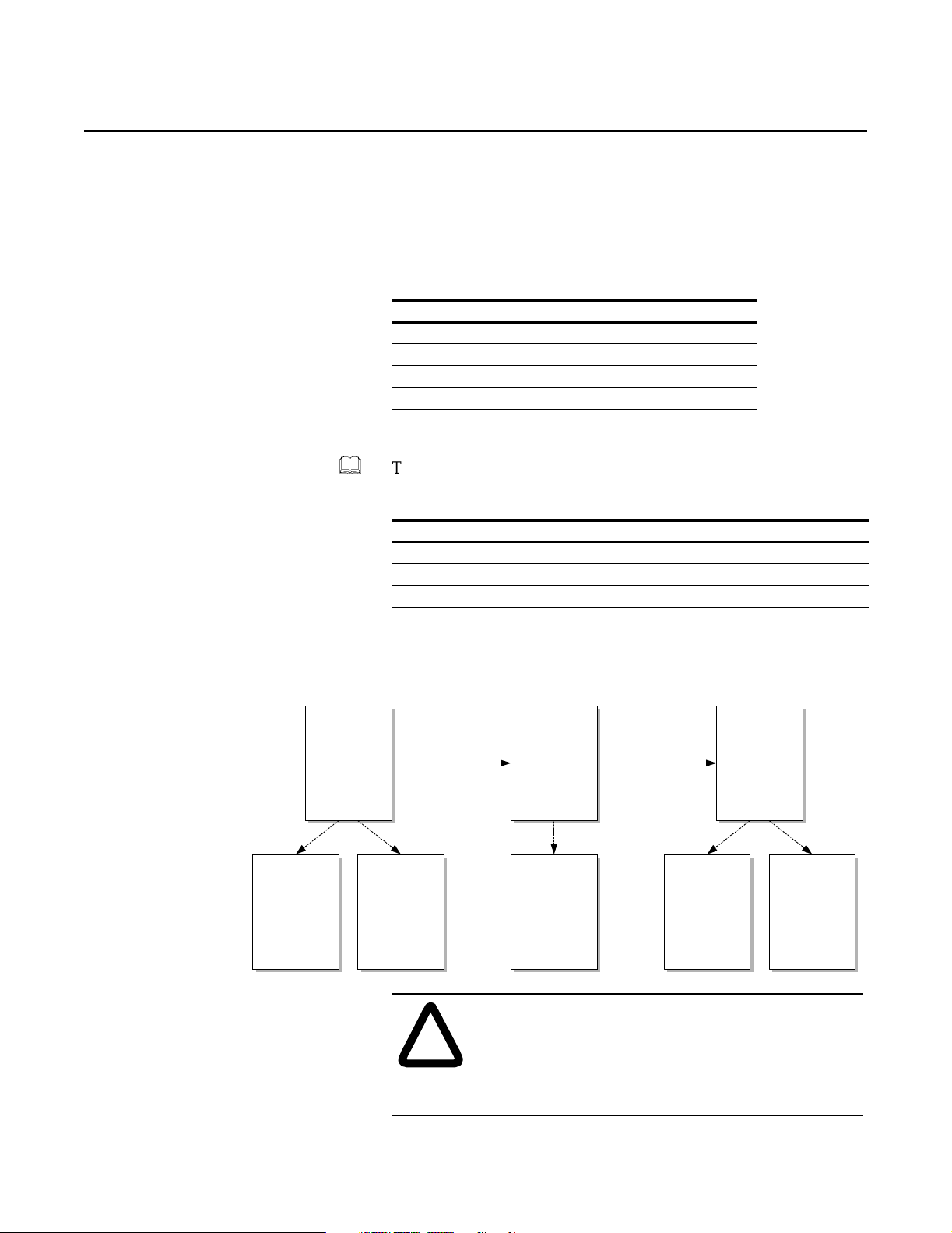
Chapter
5
Installing Your Drive
Contents This chapter will guide you in the i nstallation of your new dri ve. The
following topics will be covered:
Topic Pa ge
Resources 5-2
Physically Installing the Unit at Your Site 5-2
Preparing AC Input Entry 5-2
Installing and Configuring Your Drive 5-4
Resources
Physically
Inst alling the
Drive at Your
(This Manual)
References Reference
Receiving,
Handling, and
Stor i ng Motor
Contro l
Centers–
Instructions
(2100-5.5)
&
Site
Bull e t i n 2300
Family of Drive
Systems
Hardware–
Installation
(2300-5.1)
To properly install and configure your drive, you will need the
following publications:
Publication Title
2300-5.1
2100-5.5
1395-5.40
Bulletin 2300 Family of Drive Systems Hardware–Installation Manual
Receiving, Handling, and Storing Motor Control Centers–Instructions
1395 Digital DC Drive–User Manual
Plus, you may need to refer to your system schematics, motor/
encoder documenta tion, a nd other doc ument ation li sted in the pr eface
of this manual (for adapter boards and NEC standards).
Manual
Preparing AC
Input Entry
(This Manual)
Top Hat
Assembly
Instructions
(included with
top hat
assembly)
Installing and
Configuring
Your Drive
(This Manual)
Installation
(1395-5.40)
References
NFPA 70,
Local Codes,
Misc.
Refere nce
Manuals
AT TENTION: Electric shock or equipment damage
may occur if the d rive is not i nstalled properly . C omply
!
to the provisions listed in the National Electric Code
(NEC) and in your local codes to safely install your
drive.
Publication 2361-5.01 July 1998
Page 56

5-2 Installing Your Drive
Physically Installing the Drive
at Your Site
&
T o move and posit ion the unit a t your site, you will ne ed to follow the
instructions given in Publication 2100-5.5, titled Receiving,
Handling, And Storing Motor Control Cente rs–Instructions. This
publication will instruct you in the proper handling, moving, a nd
positioning of your new drive.
&
After the drive is properly positioned, follow the instructions given in
Publication 2300-5.1, titled Bulletin 2300 Family of Drive Systems
Hardware–Installation Manual. This publication will teach you how
to splice busbars, how to attach your unit in a multiple drive
configuration , and how to join MCC sections together (if necessary) .
Inspecting the Air Baffles
Inspect the air ba ffles and guar d s acc ord i ng to the air baffl e layouts
shown in Appendix A.
Preparing AC Input Entry If your drive ha s an extra input bay installed, you can skip this
section.
To prepare input entry, select the ideal hole placement (within the
constraints of the fol lowing dia gram), then follow the installation
steps given. The following instr uctions include directions for a top
hat assembly.
Note: When pre paring the input entry, you may need to consider
the busbar arrangement and the wir e size s. Busbar diagrams are
shown in Appendix A, and recommended wire sizes are listed
later in this chapter.
Figure 5.1
Area Available For Conduit Entry (Top View of Disconnect Bay)
1.25"
11.50"
1.14"
20.00"
(Back of Enclosure)
Area Available For
Conduit Entry
20.00"
17.72"
(Front of Enclosure)
Publication 2361-5.01 July 1998
3000A units allow a depth of
16.75"
for conduit entry.
Page 57

Installing Your Drive 5-3
1. Remove the lifting angle, if it is still attached.
2. Remove the top plate from the disconnect bay. If the drive has a
top hat assembly, this plate will not be needed.
3. If the drive has a top hat assembly, mount the assembly to the
drive (accor ding to the assembly instructions), and remove the
assembly’s top plate.
ATTENTION: The top plate must be removed from
the drive before any cutting, drilling, tapping, or welding
!
4. Punch holes for the AC input into the top plate within the area
shown in Figure 5.1. Clean the punched area to ensure that metal
shavings will not fall into the dri ve.
5. Secure the top plate to the drive (or top hat assembly), and
replace the lifting a ngle.
can be done. Failure to do so could resu lt in damage to
sensitive components.
Publication 2361-5.01 July 1998
Page 58

5-4 Installing Your Drive
Installing and Configuring
Your Drive
&
Follow the installat ion instructions given in publication 1395-5.40 to
set up your unit, referring to this c hapter for information specifically
for the 1250, 1650, and 3000A DC drives.
Drive Disconnect
A 3-phase circuit breaker or AC line fuses are included with each
drive. For circuit breaker settings and derating, refer to Appendix A.
Wiring Recommendations
The following tables show recommen ded wiring f or the 1250, 1650,
and 3000A DC drives, according to NFPA 70, 75ºC wiring. Refer to
local codes for wire sizes.
Table 5.A: Typical Wire Selections (AC Input)
DC Bus Current
(A DC)
1250 4-500 kcmil
1650 5-500 kcmil
3000 8-500 kcmil
(For Each Phase or Connection, AWG)
Incoming Wires
Table 5.B: Typical Wire Selections (Armature Connection)
DC Bus Current
(A DC)
1250 5-500 kcmil
1650 6-500 kcmil
3000 10-500 kcmil
Output Wires
(AWG)
Table 5.C: Typical Wire Selections (Field Connection)
DC Bus Current
(A DC)
1250 8 4
1650 8 4
3000 8 4
Output Lines
(43A Field, AWG)
Output Lines
(90A Field, AWG)
Publication 2361-5.01 July 1998
Page 59

Installing Your Drive 5-5
Drive Grounding
The internal drive components should already be connected to the
ground (PE) a nd zero potential (TE) buses. Connect any additional
items to PE and TE (motor, enco der, etc.) as necessary, and connect
the PE and TE buses t o ground as explained in publication 1395- 5.40.
Power Wiring
Table 5.D: Standard Field Voltage Output
AC Incoming Voltage
To Drive (V AC)
460 300
575 300
660 300
Table 5.E: Motor Connections for CCW Rotation
Connection Drive
Motor Field 1250, 1650, 3000A TB7-1
Motor Armature 1250, 1650, 3000A A1
DC Supply Output
Voltage To Field (V DC)
Drive Terminal
Connection
TB7-3
A2
AT TENTION: The motor field supply is phase
sensitive. To guard against possible drive or motor
!
damage, ensure tha t the connections com ply to
Figure 5.2.
Motor Lead
F1 (+)
F2 (-)
A1 (+)
A2 (-)
Publication 2361-5.01 July 1998
Page 60

5-6 Installing Your Drive
Figure 5.2
Power Connections–Standard Field Voltage
L3L2L1
3-Phase
Disconnect
321
TB7
A1
F2-F1+
DC Motor
Shunt Field
M
DC Motor
Armature
A2
A2-A1+
Field Transformer
For high-horse power units with a 575 or 660V AC input, the field
supply requires a transf ormer to step down the voltage to 460V.
Figure 5.3 shows the typical transform er wiring scheme.
Figure 5.3
Field Transformer
TB8
1L1
F20
575 or
660V
H1H2X1
460V
1
2
To Field
Bridge
Publication 2361-5.01 July 1998
1L3
F21
X2
Field Transformer Enclosure
3
Typical Transformer Arrangement
(used for 575V AC inputs or greater)
Page 61

Installing Your Drive 5-7
The following table shows the transf or mer sizes available, typical
wire sizes used, and the corresp onding field currents. Refer to local
codes for all wiring.
Table 5.F: Field Transformers
Tra ns fo rm er
Size (kVA)
10 12 18
15 10 28
20 8 40
50 3 90
Typical Wire
Selections (AWG)
Maximum Field
Current (A)
Installing the Field Transformer
1. Mount the transformer enclosure and re move any input/output
knockouts, as necessary (see Figure 5.4 for enclosure detai ls).
2. Ground the enclosure according to local codes.
3. Remove the top plate from the enclosure.
4. Connect the first and third phases to the transformer primary
(F20 to H1, F21 to H2).
AT TENTION: The motor field supply is phase
sensitive. To guard against possible drive or motor
!
damage, ensure that t he connections are made accord ing
to Figure 5.3.
5. Wir e the secondary back to drive TB8 (X1 to TB8-1, X2 to
TB8-3).
6. Secure the top plate on the e nclosure.
Publication 2361-5.01 July 1998
Page 62

5-8 Installing Your Drive
Figure 5.4
Field Transformer Enclosures
10 and 15kVA Transformer Enclosure
18.72"
14.22"
Mounting Hole
0.38" x 0.50"
20kVA Transformer Enclosure
Mounting Hole
0.56" Diameter
50kVA Transformer Enclosure
16.50"
23.94"
22.00"
26.50"
17.13"
27.00"
0.88"/1.13"
12.00"
16.00"
2.50"
14.00"
22.12"
Mounting Hole
0.56" Diam eter
24.50"
28.74"
2.50"
20.00"
Publication 2361-5.01 July 1998
Page 63

Installing Your Drive 5-9
Circuit Board Jumper Connections
Table 5.G: Feedback Board Jumper Setting (Field Current)
Motor Field Current
Jumper Settings
1 (J36 to J41) 1.0 – 2.4 2.0 – 4.9
2 (J37 to J42) 2.5 – 9.8 5 – 17.5
3 (J38 to J43) 9.9 – 18.6 17.6 – 37.1
4 (J39 to J44) 18.7 – 43 37.2 – 86
Table 5.H: Feedback Board Jumper Settings (Input Voltage)
43A Field Bridge 90A Field Bridge
Line Voltage
(V AC) A B C VA+ VA-
460 J7 to J22 J10 to J25 J13 to J28 J16 to J31 J19 to J34
575 J7 to J22 J10 to J25 J13 to J28 J16 to J31 J19 to J34
660 J8 to J23 J11 to J26 J14 to J29 J17 to J32 J20 to J35
Jumper Settings
Table 5.J: Power Stage Interface Board Jumper Settings
Jumper Position Purpose
J11 1 – 2 115V AC Motor Thermal Input
2 – 3 24V DC Motor Thermal Input
J12 1 – 2 115V AC Reset Input
2 – 3 24V DC Reset Input
Publication 2361-5.01 July 1998
Page 64

5-10 Installing Your Drive
Table 5.K: Main Control Board Jumper Settings
Jumper Position Purpose
J8, J9, and J10 1 – 2 +5V DC Encoder Power
2 – 3 +12V DC Encoder Power
J14 1 – 2 EE Write Enable
2 – 3 EE Write Disable
Table 5.L: 115V AC Control Circuit Current Requirements
Current 1250A Drive 1650A Drive 3000A Drive
Total Sealed Current 8A 8A 8A
Total Inrush Current 14A 14A 14A
Publication 2361-5.01 July 1998
Page 65

Installing Your Drive 5-11
Figure 5.5
115V AC Input and Contactor Control Connections
M1
ECO AST
(optional)
External
Fault/Read y
Indication
115V AC Common
115V AC
ECOAST
Voltage Source
(24V DC or
115V AC)
TB5
24V DC
115 V AC
Reset
Motor
Therm ostat
Note: 24VDC m ust
not be us ed for an y
purpose oth er then
ECOAST
TB3
12
11
10
9
8
7
6
5
4
3
2
1
24 V - OUT
24 V + OUT
24 V ECOA ST -
24 V ECOA ST +
READY/FAULT2
READ Y/FAULT 1
115V C OMMON OU T
115V ECOAST 2
115V ECOAST
Reset In
Motor Temp In
Common In
FAULTED
SYSTRIP
DCPILOT
MP
3-phase
AC
Armature
Bridge
A1
To DC
Motor
A2
MP
M1-X
M1
K
6910123
-
+
PR
43
1
6
K3
J1
J1
5
115VAC Com mon
115VAC
6
J10
+ 24 V
12 3 4
K3
K2
TP21
ISO
+ 24VDC
K3
K1
ECOAS T
ISO
K2
+ 24VDC
J9
K1
SYSTRIP
DCPILOT
A7
Power
Stage
Interfac e
Publication 2361-5.01 July 1998
Page 66

5-12 Installing Your Drive
Table 5.M: 115V AC Connections
Rating (A DC) 115V AC Input Connections
1250, 1650, 3000 TB5-5, TB5-14
Table 5.N: Terminals Used for External Control of Contactor
Rating (A DC) External Control Connections
1250, 1650, 3000 TB5-9 to TB5-10
Note: If an external control will be used, remove the jumper
across the terminals listed in the table above.
Table 5.P: Torque Values
Connections Torque
3-phase AC input (L1, L2, L3) 45 lb-ft
DC output (A1, A2) 45 lb-ft
Armature Current Ratings
See Appendix A for electrical specification charts.
Publication 2361-5.01 July 1998
Page 67

Chapter
6
Starting Up Your Drive
Contents This chapter supplements the start-up procedures in the 1395 Digital
DC Drive User Manual with information for your high-horsepower
drive. The following information will be covered in this chapter:
Topic Pa ge
Introduction 6-1
Voltage Measurements 6-1
Rated Armature and Field Currents 6-2
Feedback Scaling Parameters 6-2
Introduction When you use publication 1395-5.40 to start up your drive, you will
need to ref er to this chapter for information pertaining to the highhorsepower drives.
Voltage Measurements Table 6.A: Field AC Voltage Measurements
Drive Rating Field AC Input Measurement Points
1250, 1650, 3000A TB8-1, TB8-3
Table 6.B: 115V AC Voltage Measurements
Drive Rating 115V AC Measurement Points
1250, 1650, 3000A TB5-3, TB5-12
Table 6.C: 24V DC Voltage Measurements
Drive Rating 24V DC Measurement Points
1250, 1650, 3000A TP1 (+24V DC) to TP7 (gnd) on power stage
interface board
Publication 2361-5.01 July 1998
Page 68

6-2 Starting Up Your Drive
Table 6.D: Voltage Measurements (1250, 1650, 3000A Drives)
Test Points Expected Voltage Measured Voltage
AC Voltages
L1 to L2 Rated AC Input
L2 to L3 Rated AC Input
L3 to L1 Rated AC Input
TB8-1 to TB8-2 Rated DC Field Output
TB5-3 to TB5-12 115V AC (±10%)
Main Control Board
TP51 to TP52 +5V DC (±0.15V)
TP55 to TP57 +12V DC (±0.48V)
TP56 to TP57 -12V DC (±0.48V)
TP58 to TP53 +5V DC (±0.15V)
TP54 to TP53 +12V DC (±0.48V)
Power Stage Interface Board
TP1 to TP7 +24V DC (±6V)
Rated Armature and Field Currents Armature and field current ratings are listed in the electrical
specifications in Appe ndix A.
Publication 2361-5.01 July 1998
Page 69

Appendix
Drive Specifications
Contents This appendix lists spec ifications for your drive. The following
topics are cover ed in this appendix:
Topic Pa ge
General Specifications A-1
Unit Specifications A-2
Electrical Specifications A-3
Power Dissipation A-4
Circuit Breaker Settings A-5
Circuit Breaker Derating A-6
Input Busbars A-7
Air Baffle Layouts A-9
A
General Specifications The following ta ble expresses the general spec ifications for the 1250,
1650, and 3000A drives.
Table A: General Specifications
Subject Specifications
AC Input Frequency Tolerance 50/60Hz ±3Hz
AC Input Voltage T olerance ±10%
150% maximum DC bus current for 60 seconds,
Overload Capability
Overload Duty Cycle
Minimum Continuous Load Requirement 33% of rated DC bus continuous current
Operating Altitude Up to 1000 meters (3,300 feet)
Ambient Temperature (Operating) 0 to 40°C (32 to 104°F)
Relative Humidity (Operating/Storage) 5 to 95%, non-condensing
Ambient Temperature (Storage) -40 to 70°C (-40 to 158°F)
For altitudes greater than 1000 meters, refer to the altitude derate chart.
200% for 10 seconds, 260% for 5 seconds following
continuous operation
1 minute out of 20 minutes at rated load and
temperature
Publication 2361-5.01 July 1998
Page 70

A-2 Drive Specifications
Figure 1
Altitude Derating Chart
3000 3000 3000
3000
2800
2600
2400
2200
2000
1800
Current (Amps)
1650 1650
1600
1400
1250 1250 1250 1250
1200
1000
0 1100 2200 3300 4400 5500 6600 7700 8800 9900 11000 12100 13200
1600
2850
1550
2817
1525
1220
Altitude (Feet)
2783
1500
1190
2750
1475
1162
2717
1450
1145
2683
1425
1130
2650
1400
1115
2617
1375
1098
2583
1350
1081
2550
1320
1065
3000A
1650A
1250A
Unit Specifications The following spe cifications apply to the 1250, 1650, a nd 3000A DC
drives with standard options.
Table B: Unit Specifications
Specifications 1250A Drive 1650A Drive 3000A Drive
Height ➀ 91.5” (2324 mm) 91.5” (2324 mm) 111.5” (2832 mm) ➁
Width 75” (1905 mm) 75” (1905 mm) 95” (2413 mm)
Depth 20” (508 mm) 20” (508 mm) 20” (508 mm)
MCC Sections 3 3 4
Shipping Weight 2500 lbs (1134 kg) 2500 lbs (1134 kg) 3500 lbs (1588 kg)
Operating Sound Level 83 dB, wt. A 83 dB, wt. A 82 dB, wt. A
➀ The height includes a 1.5”-high base channel.
➁ The height for the 3000A unit includes the enclosure height (90”), the base channel (1.5”), and the
the tophat assembly (20”). The top hat assembly is shipped loose from the unit.
Publication 2361-5.01 July 1998
Page 71

Drive Specifications A-3
Electrical Specifications Table C: Electrical Specifications (1250A DC Drive)
Input Out put
Nominal Input
Voltage (V AC)
460 750 500 1100 300 43 or 90 700
460 848 500 1250 300 43 or 90 750
575 856 600 1000 300 43 or 90 750
575 909 600 1065 300 43 or 90 800
575 1060 600 1250 300 43 or 90 900
660 852 700 860 300 43 or 90 750
660 904 700 915 300 43 or 90 800
660 1011 700 1030 300 43 or 90 900
660 1217 700 1250 300 43 or 90 1000
Nominal Input
Vol tage ( V AC)
460 867 500 1280 300 43 or 90 800
460 972 500 1440 300 43 or 90 900
460 1108 500 1650 300 43 or 90 1000
575 1125 600 1330 300 43 or 90 1000
575 1385 600 1650 300 43 or 90 1250
660 1590 700 1650 300 43 or 90 1250
Nominal Input
Power ( kVA)
Nominal Armat ure
Voltage (V DC)
Nominal Armature
Current (A DC)
Maximum Field
Voltage (V DC)
Table D: Electrical Specifications (1650A DC Drive)
Input O utput
Nominal Input
Power ( kVA)
Nominal Armature
Voltage (V DC)
Nominal Armature
Current (A DC)
Maximum Field
Vol tage ( V DC)
Maximum Field
Current (A DC)
Maximum Field
Current (A DC)
Nominal HP
Nominal HP
Table E: Electrical Specifications (3000A DC Drive)
Input Output
Nominal Input
Vol tag e (V AC)
Nominal Input
Power ( kVA)
Nominal Armature
Voltage (V DC)
Nominal Armature
Current (A DC)
Maximum Field
Voltage (V DC)
Maximum Field
Current (A DC)
460 1374 500 2000 300 43 or 90 1250
460 1634 500 2400 300 43 or 90 1500
460 2024 500 3000 300 43 or 90 1750
575 1713 600 1995 300 43 or 90 1500
575 1985 600 2330 300 43 or 90 1750
575 2254 600 2660 300 43 or 90 2000
575 2531 600 3000 300 43 or 90 2250
660 1705 700 1715 300 43 or 90 1500
660 1971 700 2000 300 43 or 90 1750
660 2242 700 2290 300 43 or 90 2000
660 2508 700 2575 300 43 or 90 2250
660 2905 700 3000 300 43 or 90 2500
Nominal HP
Publication 2361-5.01 July 1998
Page 72

A-4 Drive Specifications
Power Dissipation The 1250, 1650, and 3000A DC drives dissipate power proportionally
to the armature current, as shown in the following figures.
Figure 2
Watts Dissipation vs. Armature Current (1250A DC Drive)
Heat Dissipation (W)
Armature Current (A)
Figure 3
Watts Dissipation vs. Armature Current (1650A DC Drive)
Heat Dissipation (W)
Armature Current (A)
Figure 4
Watts Dissipation vs. Armature Current (3000A DC Drive)
Heat Dissipation (W)
Armature Current (A)
Publication 2361-5.01 July 1998
Page 73

Drive Specifications A-5
Circuit Breaker Settings The 1250A DC drive has a 1200A N-frame circuit breaker with a
1200A plug. The circuit breaker shoul d be set as shown in the
following diagram.
Figure 5
Recommended Circuit Breaker Settings (1250A DC Drive)
'LJLWULS5065DWLQJ3OXJ
Push
to
Trip
Engaged
In = Ir
Remove
Short Delay
5
4
6
3
8
2
Pickup • x Ir
Digitrip RMS
7
Trip Unit
The 1650A DC drive has a 1600A R-frame circuit breaker with a
1600A plug. The circuit breaker shoul d be set as shown in the
following diagram.
Figure 6
Recommended Circuit Breaker Settings (1650A DC Drive)
'LJLWULS5065DWLQJ3OXJ
Push
to
Trip
Engaged
In = Ir
Remove
Short Delay
5
4
6
3
8
2
Pickup • x Ir
Digitrip RMS
7
Trip Unit
The 3000A DC drive has a 3000A SPB-frame circuit breaker. The
circuit breaker should be set as shown in the following diagram.
Figure 7
Recommended Circuit Breaker Settings (3000A DC Drive)
Long Delay
Setting (I
1
x In = I
Long Delay
)
Time
R
7
R
Sec
At
6 x I
R
Breaker Trips
At 6T
Test Amps
3
I
n
Test
Trip Reset
Unit Status
Inst
Setting
2.5
x I
n
Publication 2361-5.01 July 1998
Page 74

A-6 Drive Specifications
Circuit Breaker Derating Figure 8
1250A DC Drive Breaker Derating
70000
60000
50000
40000
30000
20000
10000
Breaker Interupting Rating in Amps
Figure 9
1650A DC Drive Breaker Derating
70000
480 V
575 V
660 V
0
0 5000 10000 15000
Altitude in Feet
60000
50000
40000
30000
20000
10000
Breaker Interupting Rating in Amps
0
0 5000 10000 15000
Altitude in Feet
Figure 10
1650A DC Drive Breaker Derating
120000
100000
80000
60000
40000
480 V
575 V
660 V
480 V
575 V
660 V
Publication 2361-5.01 July 1998
20000
Breaker Interupting Rating in Amps
0
0 5000 10000 15000
Altitude in Feet
Page 75

Drive Specifications A-7
Input Busbars The AC input busbars are set up in the 1250, 1650, and 3000A drives
as shown in the following figures .
Figure 11
AC Input Busbars (1250A DC Drive)
Bus Dimensions
Bus Arrangement
4 connections are
available for each phase
0.87"
1.750"
1.69"
Phase 1
(L1)
0.563"
Diameter
Phase 2
(L2)
0.250"
Phase 3
(L3)
Importa nt: If the AC line fuse option is selected for a 1250A unit,
1650A busbars (show n in Figure 12) will be equipped
with the unit rather than the 1250A busbars.
Publication 2361-5.01 July 1998
Page 76

A-8 Drive Specifications
Figure 12
AC Input Busbars (1650A DC Drive)
Bus Dimensions
Bus Arrangement
8 connections are
available for each phase
0.88
1.750
0.83
Phase 1
(L1)
1.844
Phase 2
(L2)
0.250
0.563 Diameter
Phase 3
(L3)
Figure 13
AC Input Busbars (3000A DC Drive)
Bus Dimensions
0.625
Diameter
Bus Arrangement
12 connections
are available for
each phase
0.88
0.88
1.750
Phase 1
(L1)
1.938
1.938
Phase 2
(L2)
0.188
0.188
Phase 3
(L3)
Publication 2361-5.01 July 1998
Page 77
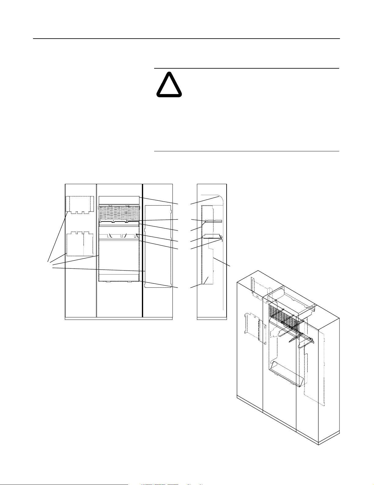
Drive Specifications A-9
Air Baffle Layouts The following diagrams show how the air baffles and guards are
arranged in the drives.
AT TENTION: Air baffles are designed to distribute
air to cool drive components. Ensure that the baffles
!
Figure 14
Air Baffle Layout (1250 and 1650A Units)
are in place when operating the drive to provide the
proper airflow and to prevent the thermoswitches or
optional airflow sensor from intermittently shut ting
down the drive.
AT TENTION: Guards are designed to direct airflow
in the drive and t o prevent injury . Ensure that the guards
are in place when operating the drive.
Baffle
Guards
Baffle
Baffle
Baffle
Baffle
Guard
Baffle
Publication 2361-5.01 July 1998
Page 78
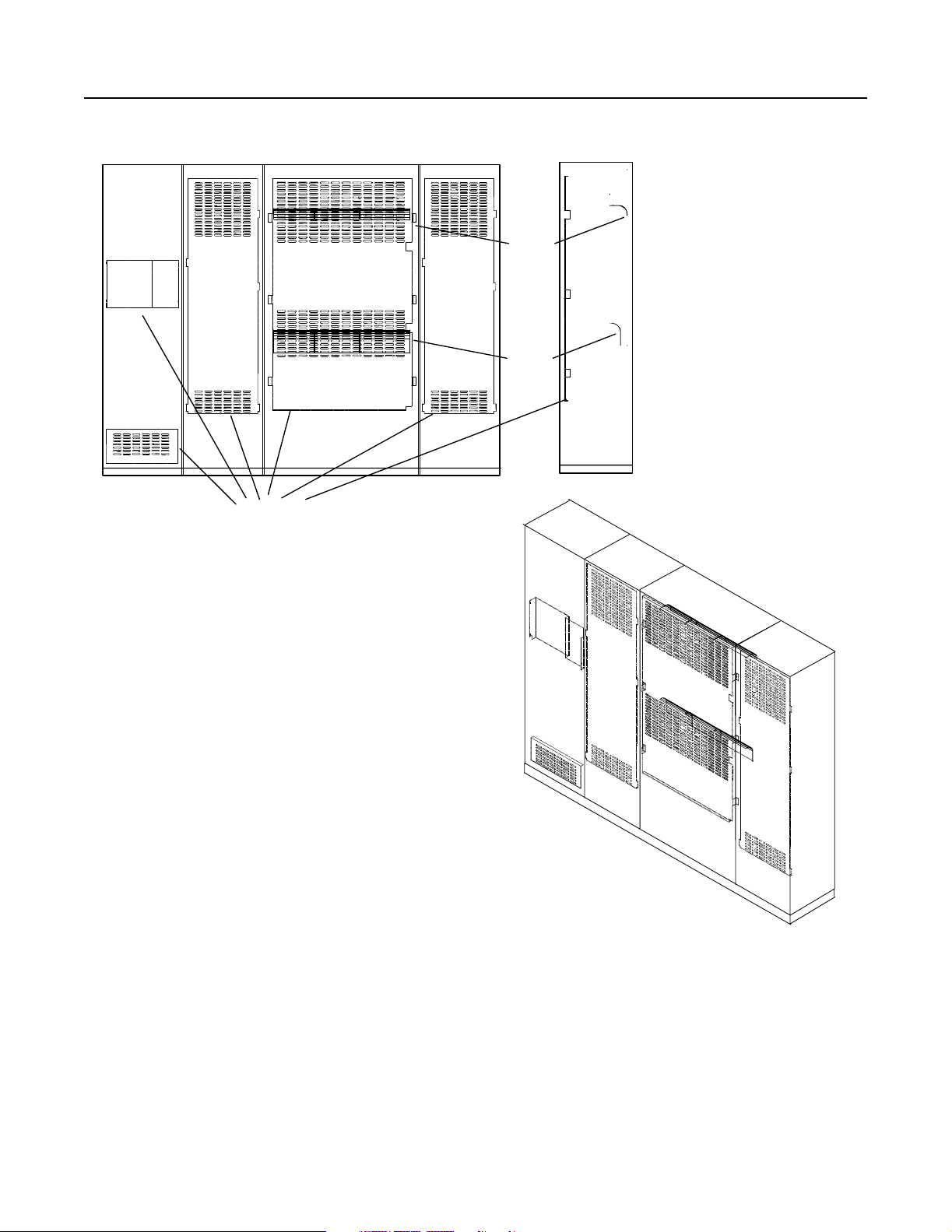
A-10 Drive Specifications
Guards
Figure 15
Air Baffle Layout (3000A Units)
Ba ffle
Baffle
Publication 2361-5.01 July 1998
Page 79

Appendix
Catalog Numbers and Spare Parts Kits
Contents This appendix provides a description of catalog numbers and lists
available spare parts kits.
To pi c Pa ge
Understanding Catalog Numbers B-1
DC Drive Catalog Numbers B-3
DC Drive Spare Parts Kits B-6
Understanding Catalog Numbers Catalog numbers consist of various components that are use d in a
drive. Each character of the catalog num ber helps identify a specific
drive. The first four numbers represe nt the family of products (for
example, 2361). The remaining characters define a specific version
or options.
B
2361
Regenerative
Option
Wiring
Type
—
Determining Catalog Numbers
To help you to understand, we will provide an example of how to
determine a catalog number for a DC drive.
The beginning portion of the cata log number for high-horsepower
1395 DC drive units would be 2361E or 2361F (E for regenerative,
F for non- regenerati ve). The remai ning por tio n of the c atalog n umber
will represent the opti ons fo r which you need to make a selec tion.
The catalog number must appear in this orde r:
Module
Size
Enclosure
AC Input Line
Voltage
—
HP
Trip Device Options
—
Publication 2361-5.01 July 1998
Page 80

B-2 Catalog Numbers and Spare Parts Kits
For example, if you were to use the table on the following pa ge to
select a drive that:
• is a regene rative unit
• supplies 1000 HP
• 3-phase AC input of 460V AC
• has a NEMA Type 1 enclosure without gaskets and door fan
filters
• has a high instantaneous trip circuit breaker
• includes the options:
• ControlNet™ communication boa rd
• 115V AC discret e adapter board
• emergency stop
The catalog number would be:
2361EA-SAB-68CM-14CN-14DAA-1B
Publication 2361-5.01 July 1998
Page 81

DC Drive Catalog Numbers
Catalog Numbers and Spare Parts Kits B-3
%XOOHWLQ
1XPEHU
8QLW
7\SH
:LULQJ
7\SH
2361 F A
E = Regenerative 1395
DC Drive
F = Non-Regenerative
1395 DC Drive
A = “A"-Type Power Wiring
R = 1250A
S = 1650A
T = 3000A
A = NEMA Type 1 without gaskets and door fan filters
J = NEMA Type 1 with gaskets and door fan filters
B = 460V AC
C = 575V AC
G = 660V AC
0RGXOH
6L]H
(QFORVXUH
$&,QSXW
/LQH9ROWDJH
+3
S A C 68 CM
7ULS
'HYLFH
2SWLRQV
64 = 700 hp
65 = 750 hp
66 = 800 hp
67 = 900 hp
68 = 1000 hp
69 = 1250 hp
CM = High AIC instantaneous trip circuit breaker with thermal magnetic plug / trip function
LF = Line fuses only
Refer to option table
70 = 1500 hp
71 = 1750 hp
72 = 2000 hp
73 = 2250 hp
74 = 2500 hp
Publication 2361-5.01 July 1998
Page 82
B-4 Catalog Numbers and Spare Parts Kits
Options
Door-Mounted Pilot Lights
Door-Mounted Pushbuttons
Door-Mounted Illuminated
Pushbuttons
Door-Mounted Switches
Drive Port A Cards
Drive Port B Cards
Tachometer Feedback
Scaling Boards
Configuration Terminals
Control Power Source
Dynamic Braking Contactor
4R = Power-on
1B = Drive stop
1JF = Jog forward
1JR = Jog reverse
1ES = Hardwared stop interface
5G = Start / Running
5A = Clear faults / Drive faulted
3 = Speed 0-1-2 selector
760A = Single-turn speed pot
14DAA = Discrete adapter, 115V AC
14DAD = Discrete adapter, 24V DC with 0.5A, 24V power supply
14DRA = Digital reference adapter, 24V DC with 0.5A, 24V power supply
14CN = ControlNet adapter
14NA = Node adapter
14MCA = Multi-communications adapter
14T033 = Scaling board for resolvers with output voltages of 0-33V DC
14T046 = Scaling board for resolvers with output voltages of 34-46V DC
14T070 = Scaling board for resolvers with output voltages of 47-70V DC
14T125 = Scaling board for resolvers with output voltages of 71-125V DC
14T178 = Scaling board for resolvers with output voltages of 126-178V DC
14T250 = Scaling board for resolvers with output voltages of 179-250V DC
766 = Door-mounted D-shell connector
766A = Door-mounted DHT (Standard Terminal)
766B = Door-mounted EHT (Enhanced Terminal)
6P = Standard capacity control transformer with primary fusing
6TB = 115V AC control power, factory wired from 115V AC control bus to drive unit
6SC = 115V AC control power supplied by others
14DB = Dynamic braking contactor option
Unit Door Nameplates
Auxiliary Contacts
Blower Starters
Protection
Input Option
Field Supply Upgrade
Field Voltage Step-Down
Options for Units with 575
or 660V AC Inputs
Miscellaneous
M3EW = White background with black lettering; phenolic label
N3EB = Black background with white lettering; phenolic label
N3ER = Red background with white lettering; phenolic label
989X = (2) Normally open and (2) normally closed contactors mounted internally if 1250/1650A
OR
(4) Normally open and (4) normally closed contactors mounted internally if 3000A unit
14BN = (1) NEMA size 1 FVNR starter assembly with 30A fuse blocks mounted within the drive unit
14B2N = (2) NEMA size 1 FVNR starter assembly with 30A fuse blocks mounted within the drive unit
14B2NX = (2) NEMA size 2 FVNR starter assembly with 60A fuse blocks mounted within the drive unit
14BI = (1) IEC, 24A starter assembly mounted with 30A fuse blocks within the drive unit
14B2I = (2) IEC, 24A starter assembly mounted with 30A fuse blocks within the drive unit
14B2IX = (2) IEC, 30A starter assembly mounted with 60A fuse blocks within the drive unit
14LSP = Line RC suppressor module
14AFL = Air flow loss switches
14HBC = AC power input is wired from the horizontal thru-bus to the circuit breaker
14FX = Field supply upgrade for fields requiring 43 to 90A
14SD28 = Field transformer for field currents up to 28A
14SD40 = Field transformer for field currents up to 40A
14SD90 = Field transformer for field currents up to 90A
14WLBL = Brady Datab ™ wire labels
J12 = 115V DC, 15A duplex receptacle, customer-wired
J11 = Audio phone jack
Publication 2361-5.01 July 1998
Page 83

Catalog Numbers and Spare Parts Kits B-5
Footnotes
Non-regenerative units not offered for 3000A modules.
Units accommodate top entry and bottom exit. An additional section is required for bottom entry and a separate additional
section is required for top exit.
Units configured for 575 or 660V AC inputs require field transformers. The field supply modules require an input voltage of
460V AC and the field transformer is utilized to step-down 575 or 660V AC inputs to 460V AC. The base unit price of a 575
or 660V AC input drive includes a field transformer (and fusing) that provides up to 18A to the field supply module. Select a
field transformer upgrade option when you need to supply more current to the field supply module. All field transformers
come standard in a NEMA Type 1 enclosure. Nominal field currents based on 85% efficiency, unit control power usage, and
a 300V field supply.
Add option codes here and separate option code with dashes.
Devices are 800T-type.
If selected, you must select (1)
Drive Port A Card. If you select 5+ input devices or 3+ output devices, you must select Drive
Port A Card "14DRA."
If selected, you must also select option "1B."
Maximum number of cards allowed is one for Port A, and one for Port B.
If your motor has a DC tachometer, select the appropriate scaling board.
You may select up to one option from this group.
You must select one option from this group.
For 1250 to 3000A modules, you may select option "14DB." This option includes a dynamic braking contactor mounted in a
separate 20" MCC section
The line RC suppressor is recommended for installations where the primary of the distribution transformer is 2300V AC or
greater.
This option is only valid for 1250A and 1650A DC drives. You must specify a AC thru bus option with a current capacity larger
than the continuous input current rating of the drive unit.
Units come standard with a field supply module rated to supply field currents up to 43A. This field supply option allows you
to supply up to 90A to the motor field. If you are selecting a 575 or 660V AC input and this field supply option, you must
select field voltage step-down option "14SD90".
Units come standard with cloth wire labels. Datab labels offer the added protection of a clear plastic cover on top of the
labels.
Customer supplies 115V AC control power and wiring to the duplex receptacle.
Publication 2361-5.01 July 1998
Page 84

B-6 Catalog Numbers and Spare Parts Kits
DC Drive Spare Parts Kits These spare parts kits are designe d to pro vide you with the necessary
parts to repair and maintai n your drive .
What Does a Spare Parts Kit Include?
A spare parts kit includes the ite ms in the quantities described in
Tables A, B, and C. Each spare parts kit also contains installation
instructions .
Which Table Do I Use?
For a drive with an
input voltage of:
460V AC Table A
575V AC Table B
660V AC Table C
Refer to:
Significance of Level Numbers
Level numbers are used to recommend stocking locations for the
various spare parts kits. Level descriptions are as follows:
Level Number Level Description Recommended Stocking Location(s)
1 Major Assemblies Large users, OEMs, distributors, and GTS
2 Minor Assemblies Distributors and GTS
3 Discrete Components GTS
Publication 2361-5.01 July 1998
Page 85

Catalog Numbers and Spare Parts Kits B-7
Definition of Terms Used to Describe "Qty in Kit"
The column "Qty in Kit" in Tables A, B, and C represents how many
components you can expect to find as f ollow:
Level Number Example “Qty in Kit” Kit Contains
Kits containing
one item
Kits containing
multiple items
1
1 each
1 PCB / 4 fuses
1 set
The specified quantity of the item
described
The specified quantity of each item
described
The specified quantity of each item, as
described
The quantity of the specified items
required for one drive (per set)
Catalog Number Description
2361 -SP A 01 A
Bulletin
Number
Spare Part
Designator
Spare Part
Type
Kit Number Revision
Letter
Publication 2361-5.01 July 1998
Page 86

B-8 Catalog Numbers and Spare Parts Kits
Table A: Spare Parts Kits for Drives with 460V AC Inputs
Level Catalog Number
Description
Qty in Kit
1 2361-SPE01A Control Fuses, 1250 - 3000A DC units 2 sets
1 2361-SPE12A Line Fuses, 1250A DC units 1 set
1 2361-SPE13A Line Fuses, 1650A DC units 1 set
1 2361-SPE14A Line Fuses, 3000A DC units 1 set
1 2361-SPM01A Feedback Board, 1250 - 3000A DC units 1
1 2361-SPM03A Armature-Pulse Transformer Board, 1250 - 3000A DC units 1
1 2361-SPM04A Field Pulse Transformer Board for Option 14FX, 1250 - 3000A DC units 1
2 2300-SPB01A Line RC Suppressor (Option 14LSP), 1250 - 3000A DC units
1 PCB / 2 sets of
2 2300-SPJ02A Line MOVs, 1250 - 3000A DC units 1 set
2 2300-SPP01A Air Flow Switch PCB Kit (Option 14AFL), 1250 - 1650A DC units
2 2300-SPP02A Air Flow Switch PCB Kit (Option 14AFL), 3000A units
1 PCB / 1 power
supply (.5A)
1 PCB / 1 power
supply (1.1A)
2 2361-SPA01A Positive (Top) Regenerative Armature Assemblies, 1250A DC units 1
2 2361-SPA02A Negative (Bottom) Regenerative Armature Assemblies, 1250A DC units 1
2 2361-SPA03A Positive (Top) Regenerative Armature Assemblies, 1650A DC units 1
2 2361-SPA04A Negative (Bottom) Regenerative Armature Assemblies, 1650A DC units 1
2 2361-SPA05A Positive (Top) Regenerative Armature Assemblies, 3000A DC units 1
2 2361-SPA06A Negative (Bottom) Regenerative Armature Assemblies, 3000A DC units 1
2 2361-SPA07A Field SCR Module for Option 14FX, 1250 - 3000A DC units 1
2 2361-SPA08A Positive (Top) Non-Regenerative Armature Assemblies, 1250A DC units 1
2 2361-SPA09A Negative (Bottom) Non-Regenerative Armature Assemblies, 1250A DC units 1
2 2361-SPA10A Positive (Top) Non-Regenerative Armature Assemblies, 1650A DC units 1
2 2361-SPA11A Negative (Bottom) Non-Regenerative Armature Assemblies, 1650A DC units 1
2 2361-SPB01A Snubber Assembly, 1250 - 1650A DC units 1
2 2361-SPB02A Snubber Assembly, 3000A DC units 1
2 2361-SPE08A Individual Power Fuses, 1250A DC units 2
2 2361-SPE09A Individual Power Fuses, 1650A DC units 2
2 2361-SPE10A Individual Power Fuses, 3000A DC units 3
2 2361-SPE11A Power Fuse Assembly, 3000A DC units
1 assembly /
2 2361-SPG01A Armature SCRs, 1250A DC units 2
2 2361-SPG02A Armature SCRs, 1650A DC units 2
2 2361-SPG03A Armature SCRs, 3000A DC units 2
2 2361-SPK01A Additional Control Board Stack Power Supply, 1250 - 3000A DC units 1
2 2361-SPM02A Gate Interface Board, 1250 - 3000A DC units 1
3 2361-SPH01A Bridge Fan and Capacitor, 1250 - 1650A DC units 1 each
3 2361-SPH02A Bridge Fan and Capacitor, 3000A DC units 1 each
3 2361-SPH03A Slide-In Fan and Capacitor, 3000A DC units 1 each
fuses
3 fuses
Publication 2361-5.01 July 1998
Page 87

Catalog Numbers and Spare Parts Kits B-9
Table B: Spare Parts Kits for Drives with 575V AC Inputs
Level Catalog Number
Description
Qty in Kit
1 2361-SPE01A Control Fuses, Option 14SD40, 1250 - 3000A DC units 2 sets
1 2361-SPE02A Control Fuses, No Field Voltage Step Down Option, 1250 - 3000A DC units 2 sets
1 2361-SPE03A Control Fuses, Option 14SD28, 1250 - 3000A DC units 2 sets
1 2361-SPE04A Control Fuses, Option 14SD90, 1250 - 3000A DC units 2 sets
1 2361-SPE12A Line Fuses, 1250A DC units 1 set
1 2361-SPE13A Line Fuses, 1650A DC units 1 set
1 2361-SPE14A Line Fuses, 3000A DC units 1 set
1 2361-SPM01A Feedback Board, 1250 - 3000A DC units 1
1 2361-SPM03A Armature-Pulse Transformer Board, 1250 - 3000A DC units 1
1 2361-SPM04A Field Pulse Transformer Board, Option 14FX, 1250 - 3000A DC units 1
2 2300-SPB01A Line RC Suppressor (Option 14LSP), 1250 - 3000A DC units
1 PCB / 2 sets of
2 2300-SPJ03A Line MOVs, 1250 - 3000A DC units 1 set
2 2300-SPP01A Air Flow Switch PCB Kit (Option 14AFL), 1250 - 1650A DC units
2 2300-SPP02A Air Flow Switch PCB Kit (Option 14AFL), 3000A units
1 PCB / 1 power
supply (.5A)
1 PCB / 1 power
supply (1.1A)
2 2361-SPA01A Positive (Top) Regenerative Armature Assemblies, 1250A DC units 1
2 2361-SPA02A Negative (Bottom) Regenerative Armature Assemblies, 1250A DC units 1
2 2361-SPA03A Positive (Top) Regenerative Armature Assemblies, 1650A DC units 1
2 2361-SPA04A Negative (Bottom) Regenerative Armature Assemblies, 1650A DC units 1
2 2361-SPA05A Positive (Top) Regenerative Armature Assemblies, 3000A DC units 1
2 2361-SPA06A Negative (Bottom) Regenerative Armature Assemblies, 3000A DC units 1
2 2361-SPA07A Field SCR Module for Option 14FX, 1250 - 3000A DC units 1
2 2361-SPA08A Positive (Top) Non-Regenerative Armature Assemblies, 1250A DC units 1
2 2361-SPA09A Negative (Bottom) Non-Regenerative Armature Assemblies, 1250A DC units 1
2 2361-SPA10A Positive (Top) Non-Regenerative Armature Assemblies, 1650A DC units 1
2 2361-SPA11A Negative (Bottom) Non-Regenerative Armature Assemblies, 1650A DC units 1
2 2361-SPB01A Snubber Assembly, 1250 - 1650A DC units 1
2 2361-SPB02A Snubber Assembly, 3000A DC units 1
2 2361-SPE08A Individual Power Fuses, 1250A DC units 2
2 2361-SPE09A Individual Power Fuses, 1650A DC units 2
2 2361-SPE10A Individual Power Fuses, 3000A DC units 3
2 2361-SPE11A Power Fuse Assembly, 3000A DC units
1 assembly /
2 2361-SPG01A Armature SCRs, 1250A DC units 2
2 2361-SPG02A Armature SCRs, 1650A DC units 2
2 2361-SPG03A Armature SCRs, 3000A DC units 2
2 2361-SPK01A Additional Control Board Stack Power Supply, 1250 - 3000A DC units 1
2 2361-SPM02A Gate Interface Board, 1250 - 3000A DC units 1
3 2361-SPH01A Bridge Fan and Capacitor, 1250 - 1650A DC units 1 each
3 2361-SPH02A Bridge Fan and Capacitor, 3000A DC units 1 each
3 2361-SPH03A Slide-In Fan and Capacitor, 3000A DC units 1 each
fuses
3 fuses
Publication 2361-5.01 July 1998
Page 88

B-10 Catalog Numbers and Spare Parts Kits
Table C: Spare Parts Kits for RGUs with 660V AC Inputs
Level Catalog Number
Description
Qty in Kit
1 2361-SPE05A Control Fuses, No Field Voltage Step Down Option, 1250 - 3000A DC units 2 sets
1 2361-SPE06A Control Fuses, Option 14SD28, 1250 - 3000A DC units 2 sets
1 2361-SPE06A Control Fuses, Option 14SD40, 1250 - 3000A DC units 2 sets
1 2361-SPE07A Control Fuses, Option 14SD90, 1250 - 3000A DC units 2 sets
1 2361-SPE12A Line Fuses, 1250A DC units 1 set
1 2361-SPE13A Line Fuses, 1650A DC units 1 set
1 2361-SPE14A Line Fuses, 3000A DC units 1 set
1 2361-SPM01A Feedback Board, 1250 - 3000A DC units 1
1 2361-SPM03A Armature-Pulse Transformer Board, 1250 - 3000A DC units 1
1 2361-SPM04A Field Pulse Transformer Board for Option 14FX, 1250 - 3000A DC units 1
2 2300-SPB02A Line RC Suppressor (Option 14LSP), 1250 - 3000A DC units
1 PCB / 2 sets of
2 2300-SPJ03A Line MOVs, 1250 - 3000A DC units 1 set
2 2300-SPJ04A Air Flow Switch PCB Kit (Option 14AFL), 3000A units
2 2300-SPP01A Air Flow Switch PCB Kit (Option 14AFL), 1250 - 1650A DC units
1 PCB / 1 power
supply (1.1A)
1 PCB / 1 power
supply (.5A)
2 2361-SPA01A Positive (Top) Regenerative Armature Assemblies, 1250A DC units 1
2 2361-SPA02A Negative (Bottom) Regenerative Armature Assemblies, 1250A DC units 1
2 2361-SPA03A Positive (Top) Regenerative Armature Assemblies, 1650A DC units 1
2 2361-SPA04A Negative (Bottom) Regenerative Armature Assemblies, 1650A DC units 1
2 2361-SPA05A Positive (Top) Regenerative Armature Assemblies, 3000A DC units 1
2 2361-SPA06A Negative (Bottom) Regenerative Armature Assemblies, 3000A DC units 1
2 2361-SPA07A Field SCR Module for Option 14FX, 1250 - 3000A DC units 1
2 2361-SPA08A Positive (Top) Non-Regenerative Armature Assemblies, 1250A DC units 1
2 2361-SPA09A Negative (Bottom) Non-Regenerative Armature Assemblies, 1250A DC units 1
2 2361-SPA10A Positive (Top) Non-Regenerative Armature Assemblies, 1650A DC units 1
2 2361-SPA11A Negative (Bottom) Non-Regenerative Armature Assemblies, 1650A DC units 1
2 2361-SPB01A Snubber Assembly, 1250 - 1650A DC units 1
2 2361-SPB02A Snubber Assembly, 3000A DC units 1
2 2361-SPE08A Individual Power Fuses, 1250A DC units 2
2 2361-SPE09A Individual Power Fuses, 1650A DC units 2
2 2361-SPE10A Individual Power Fuses, 3000A DC units 3
2 2361-SPE11A Power Fuse Assembly, 3000A DC units
1 assembly /
2 2361-SPG01A Armature SCRs, 1250A DC units 2
2 2361-SPG02A Armature SCRs, 1650A DC units 2
2 2361-SPG03A Armature SCRs, 3000A DC units 2
2 2361-SPK01A Additional Control Board Stack Power Supply, 1250 - 3000A DC units 1
2 2361-SPM02A Gate Interface Board, 1250 - 3000A DC units 1
3 2361-SPH01A Bridge Fan and Capacitor, 1250 - 1650A DC units 1 each
3 2361-SPH02A Bridge Fan and Capacitor, 3000A DC units 1 each
3 2361-SPH03A Slide-In Fan and Capacitor, 3000A DC units 1 each
fuses
3 fuses
Publication 2361-5.01 July 1998
Page 89

Index
A
Adapter Boards,
See also References
Air Baffles,
Altitude Derating,
Altitude Specifications,
Armature Bridge,
B
Busbar Dimensions,
C
Catalog Numbers,
Circuit Breaker Settings,
Components
24V DC Power Supply,
AC Line RC Suppressor,
Adapter Boards,
See also References
Armature-Pulse Transformer Boards,
1-4, 1-6
A-9
A-2
A-1
1-14, 1-15
A-7
B-1–B-7
A-5
1-10
1-13
1-4, 1-6
1-16
Busbars,
Circuit Breakers,
DC Contactors,
Feedback Board,
Field Bridge,
Field Transformer,
Field-Pulse Transformer Board,
Gate Interface Board,
Main Control Board,
Overview,
Power Stage Interface Board,
Silicon-Controlled Rectifiers (SCRs),
1-12, A-7
1-12, A-5
1-16
1-3, 1-7, 1-10
1-7, 1-17, 1-18
1-17, 5-6–5-8
1-7, 1-18
1-3, 1-11
1-3, 1-4, 1-5
1-3
1-3, 1-7, 1-8
1-16
Snubbers,
1-16
1-3,
1-15,
Symbols
1250A Drive,
1650A Drive,
3000A Drive,
Unit Power Supply,
Unit Power Supply Board,
Connections,
D
Drives
1250A,
1650A,
3000A,
Catalog Numbers,
Dimensions,
Electrical Specifications,
Installing,
Operating Sound Levels,
Overload Capability,
Overview,
Power Dissipation,
Receiving,
Safety Precautions,
Shipping Weight,
Specifications,
Startup,
Support,
F
Features
Standard Features,
Standard Options,
Field Bridge,
Field Transformer,
1-3
2-1–2-8
3-1–3-8
4-1–4-8
A-2
5-1–5-12
1-1
P-5
A-2
A-1–A-4
6-1
P-6
1-7, 1-17, 1-18
1-17, 5-6–5-8
2-6
3-6
4-6
1-7
1-3, 1-9
B-1–B-7
A-3
A-2
A-1
A-4
P-2
1-1, B-3, B-5
1-2, B-3–B-5
Publication 2361-5.01 July 1998
Page 90

I–2 Index
I
Incoming Devices,
Installation,
J
Jumper Settings,
M
Measurement Points,
O
Options,
Overload Capability,
P
Power Dissipation,
5-1–5-12
B-3–B-5
1-12
5-9–5-10
A-4
6-1
A-1
Specifications,
Altitude,
Drive Dimensions,
Drive Weight,
Electrical,
Operating Sound Levels,
Overload Capability,
Temperature,
Support,
T
Temperature Specifications,
W
Wiring,
5-4, 5-5, 5-7
A-1–A-4
A-1, A-2
A-2
A-2
A-3
A-1
A-1
P-6
A-2
A-1
R
Ratings,
Receiving Your Drive System,
References,
Related Documentation,
Safety Precautions,
Schematics
A-3
P-5
P-4
P-4
S
P-2
115V AC and Contactor Control Connections,
5-11
1250A Drive,
1650A Drive,
3000A Drive,
Overview,
Spare Parts Kits,
2-2–2-5
3-3–3-5
4-3–4-5
1-3
B-1, B-8–B-10
Publication 2361-5.01 July 1998
Page 91

Publication 2361-5.01 July 1998 P/N 185409
1998 Rockwell International. All Rights Reserved. Printed in USA
 Loading...