

Page 1
Installation Instructions
Installing Your 1394C Power Connector
Key Kit
Catalog Number 1394C-CONN-KEY
Introduction
Systems this Kit Applies to
What this Kit Contains
This publication pro vides installati on instructions for the 1394C
power connector key kit (catalog number 1394C-CONN-KEY). Use
this document in conjunction with the 1394 Digital AC Multi-Axis
Motion Control System User Manual (publication 1394-5.0).
This kit applies to the following 1394C system modules:
• 1394C-SJT05-A
• 1394C-SJT05-C, -C-RL
• 1394C-SJT05-T, -T-RL
• 1394C-SJT05-L, -L-RL
• 1394C-SJT10-A
• 1394C-SJT10-C, -C-RL
• 1394C-SJT10-T, -T-RL
• 1394C-SJT10-L, -L-RL
This kit cont ains:
• One key wheel (with six keys).
Key Wheel
• One input power conne ct or plug (keyed, with terminals labe led
U, V, W, and PE).
• One logic power connector plug (with terminals labeled W1 and
W2).
• One shunt power connector plug (with jumper and terminals
labeled COL, INT, and DC+).
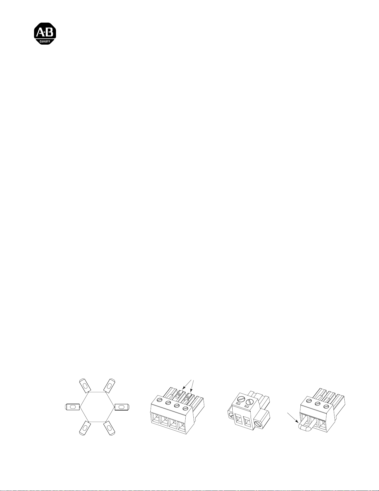
Figure 1
Kit Contents
Keys
UVW
P
Input Power
Connector Plug
W1 W2
E
Logic Power
Connector Plug
Publication 1394-IN023A-EN-P — July 2000
Jumper
COL INT DC+
Shunt Power
Connector Plug
Page 2
2 Installing Your 1394C Power Connector Key Kit
Installing the Key Kit
Installation of you r 13 9 4 C power connector key kit involves the
replacement of the system module power connector plugs and the
insertion of keys into specified system module terminals.
The replacement plugs are keyed and labeled to prevent an improper
power conne ction. F ollow the procedure starting belo w t o in stal l your
1394C power connec tor key kit.
ATTENTION: The 1394 system module contains
ESD (Elect rostatic Disc h arge) sensitive parts and
!
assemblies. Static control p recau tions are required
when installing, testing, servicing, or repairing this
device. Component damage can result if ESD co ntrol
procedures are not followed. If you are not familiar
with static control procedures, refer to Guarding
Against Electrostatic Damage (publication
8000-4.5.2), or any other appli ca bl e ESD Protection
Handbook.
Removing the Power Connector Plugs
To remove the three power connector plugs:
1. Remove all 24V control power, contactor enable power, and
360/480V AC input power from the system.
ATTENTION: This product contain s stored energy
devices. To av oid hazard of electrica l shock, wait f ive
!
minutes or verif y that all voltage on the system bus
network has been discharged before attempting to
service or repair this unit. Only qualified personnel
familiar with solid state control equipment and safety
procedures in publication NFPA 70E or applicable
local codes should attempt this procedure.
Publication 1394-IN023A-EN-P — July 2000
Page 3
Installing Your 1394C Power Connector Key Kit 3
2. If not already done, label each of the wires leading to the three
connectors using small strips of tape. Refer to Figure 2 for
connector locations.
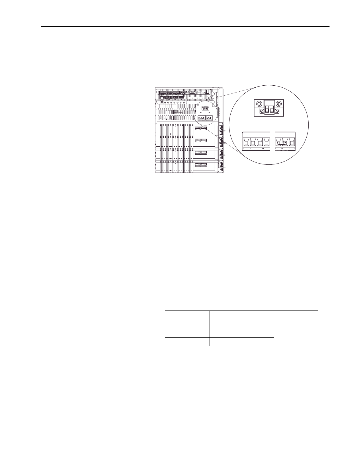
Figure 2
1394C Power Connectors
Logic Power
Connector
W1 W2
Input Power
Connector
U V W
1394 Bottom View
Shunt Power
PE
Connector
COL INT DC+
Note: If an external shunt resistor is not connected, a jumper is
installed (between COL and INT) as shown in the figure
above.
3. Remove the three power connector plugs from the bottom of the
1394C system module.
Replacing the Logic Power Connector Plug
To replace the logic power connector plug:
1. Loosen the screws in the old logic power connector and remove
the wires from each terminal (refer to Figure 2 for connector
location).
2. Insert the wires in to th e replacement connector plug (supplied in
the kit) as sh o w n in the table be low.
Insert the wir es
labeled:
W1 W1
W2 W2
Into the connector
plug terminals labeled:
Tighten to this
torque value:
0.56-0.62 N-m
(5.0-5.6 lb-in.)
3. Gently pull on each wire and make sur e it does not come out of it s
terminal. Re-insert and tighten any loose wires.
Publication 1394-IN023A-EN-P — July 2000
Page 4

4 Installing Your 1394C Power Connector Key Kit
Replacing the Input Power Connector Plug
To replace the input power connect or plug:
1. Loosen the scre ws in the old input po wer conne ctor plug and
remove the wires from each terminal (refer to Fig u r e 2 for
connector location).
2. Insert the wires in to th e replacement connector plug (supplied in
the kit) as sh o w n in the table be low.
Insert the wir es
labeled:
Into the connector
plug terminals labeled:
Tighten to this
torque value:
U U
V V
W W
0.56-0.62 N-m
(5.0-5.6 lb-in.)
PE PE
3. Gently pull on each wire and make sur e it does not come out of it s
terminal. Re-insert and tighten any loose wires.
4. Verify that keys are inserted into the beveled slots above
terminals V and W of power connector plug, as shown in the
figure below. If necessary, insert keys from the key wheel
supplied in the kit.
Figure 3
Inserting Keys into Connectors
1394C-SJT
Bottom View
xx-x
Logic power
connector
Publication 1394-IN023A-EN-P — July 2000
Input power
connector
Keys
(in replacement connector)
Replacement
input power
connector plug
U V W
Shunt power
connector
Keys
(from key wheel)
PE
Page 5

Installing Your 1394C Power Connector Key Kit 5
Replacing the Shunt Power Connector Plug
To replace the shunt power connector pl ug:
1.
If the 1394-SR10A
shunt resistor is:
Installed
Not installed Go to main step 3.
2. Remove jumper from the replacement connector plug (supplied
in the kit) and insert the wires as shown in the table below.
Then:
1. Loosen the screws i n the old s hunt
power connector plug and remove
the wires from each terminal
(refer to Figure 2 for connector
location).
2. Go to main step 2.
Insert the wir es
labeled:
COL COL
DC+ DC+
Into the connector
plug terminals labeled:
Tighten to this
torque value:
0.56-0.62 N-m
(5.0-5.6 lb-in.)
3. Gently pull on each wire (or jumper) and make sure it does not
come out of its te rminal(s). Re-insert and ti ghten any loose wires.
Inserting Keys into the System Module Connectors
1. Insert a ke y int o the b eveled slot above the i npu t po wer connec tor
terminal on the f ar right. This termin al lines up with the connec tor
plug terminal labeled PE (refer to Figure 3 for key placement).
2. Insert a key into th e beveled slot ab ove the shunt powe r connector
terminal on the far left. This terminal lines up with the connector
plug terminal labeled COL (refer to Figure 3 for key placement).
Publication 1394-IN023A-EN-P — July 2000
Page 6

6 Installing Your 1394C Power Connector Key Kit
Re-applying Power to Your 1394C System
To re-apply power to your 1394 C sys te m:
1. Re-connect the three connect or plug s as shown in the table below
(refer to Figure 2 for connector locations
).
Connect the plug
Into this system module connector:
labeled:
W1 W2 Input logic connector
U V W PE Input power connect or
COL INT DC+ Shunt power co nnector
2. Re-apply power to your system.
3. Check for proper opera tion. Refer to your 1394 Digital AC
Multi-Axis Motion Control System U ser Manua l (publication
1394-5.0) for additional start-up information.
Publication 1394-IN023A-EN-P — July 2000
Page 7

Installing Your 1394C Power Connector Key Kit 7
Publication 1394-IN023A-EN-P — July 2000
Page 8

Publication 1394-IN023A -EN -P — July 2000 195891
For more information refer to our web site: www.ab.com/motion
For Rockwell Automation Technical Support information refer to: www.rockwellautomation.com/support or Tel: (1) 440.646.3434
Copyright 2000 Rockwell International. All Rights Reser ved. Printed in USA.
 Loading...