

Page 1

Introduction Chapter 1
Manual Objectives 1-1. . . . . . . . . . . . . . . . . . . . . . . . . . . . . . . . . . . . . . . . .
1391 Series D 1-1. . . . . . . . . . . . . . . . . . . . . . . . . . . . . . . . . . . . . . . . . . . . .
General Precautions 1-2. . . . . . . . . . . . . . . . . . . . . . . . . . . . . . . . . . . . . . . .
Controller Description 1-2. . . . . . . . . . . . . . . . . . . . . . . . . . . . . . . . . . . . . .
Standard Features 1-3. . . . . . . . . . . . . . . . . . . . . . . . . . . . . . . . . . . . . . . . . .
Options/Modifications 1-4. . . . . . . . . . . . . . . . . . . . . . . . . . . . . . . . . . . . . .
Controller Layout 1-4. . . . . . . . . . . . . . . . . . . . . . . . . . . . . . . . . . . . . . . . . .
Specifications Chapter 2
Chapter Objectives 2-1. . . . . . . . . . . . . . . . . . . . . . . . . . . . . . . . . . . . . . . . .
Controller Specifications 2-1. . . . . . . . . . . . . . . . . . . . . . . . . . . . . . . . . . . .
Environmental Specifications 2-2. . . . . . . . . . . . . . . . . . . . . . . . . . . . . . . .
Controller Power Dissipation 2-2. . . . . . . . . . . . . . . . . . . . . . . . . . . . . . . .
Transformer Power Dissipation 2-2. . . . . . . . . . . . . . . . . . . . . . . . . . . . . . .
Table of Contents
1391B-ES Instruction Manual
Receiving, Unpacking and Chapter 3
Inspection
Chapter Objectives 3-1. . . . . . . . . . . . . . . . . . . . . . . . . . . . . . . . . . . . . . . . .
Receiving 3-1. . . . . . . . . . . . . . . . . . . . . . . . . . . . . . . . . . . . . . . . . . . . . . . .
Unpacking 3-1. . . . . . . . . . . . . . . . . . . . . . . . . . . . . . . . . . . . . . . . . . . . . . .
Inspection 3-1. . . . . . . . . . . . . . . . . . . . . . . . . . . . . . . . . . . . . . . . . . . . . . . .
Storing 3-1. . . . . . . . . . . . . . . . . . . . . . . . . . . . . . . . . . . . . . . . . . . . . . . . . .
Description of Operation Chapter 4
Chapter Objectives 4-1. . . . . . . . . . . . . . . . . . . . . . . . . . . . . . . . . . . . . . . . .
General 4-1. . . . . . . . . . . . . . . . . . . . . . . . . . . . . . . . . . . . . . . . . . . . . . . . . .
300V DC Power Bus Supply 4-1. . . . . . . . . . . . . . . . . . . . . . . . . . . . . . . . .
PWM Operation 4-1. . . . . . . . . . . . . . . . . . . . . . . . . . . . . . . . . . . . . . . . . . .
Shunt Regulator Operation 4-2. . . . . . . . . . . . . . . . . . . . . . . . . . . . . . . . . .
Logic Power Supply 4-3. . . . . . . . . . . . . . . . . . . . . . . . . . . . . . . . . . . . . . .
Logic Control Boards 4-3. . . . . . . . . . . . . . . . . . . . . . . . . . . . . . . . . . . . . .
Fault Monitoring and Detection 4-4. . . . . . . . . . . . . . . . . . . . . . . . . . . . . . .
Isolated Current Sensing 4-5. . . . . . . . . . . . . . . . . . . . . . . . . . . . . . . . . . . .
Integral Circuit Breaker 4-5. . . . . . . . . . . . . . . . . . . . . . . . . . . . . . . . . . . . .
Line/DB Contactor 4-5. . . . . . . . . . . . . . . . . . . . . . . . . . . . . . . . . . . . . . . . .
Power Driver Board 4-5. . . . . . . . . . . . . . . . . . . . . . . . . . . . . . . . . . . . . . . .
A Quad B Board 4-5. . . . . . . . . . . . . . . . . . . . . . . . . . . . . . . . . . . . . . . . . .
Starting and Stopping 4-5. . . . . . . . . . . . . . . . . . . . . . . . . . . . . . . . . . . . . .
Power-Up/Down Sequence 4-7. . . . . . . . . . . . . . . . . . . . . . . . . . . . . . . . . .
i
Page 2

Table of Contents
1391B-ES Instruction Manual
Inputs, Outputs and Adjustments Chapter 5
Chapter Objectives 5-1. . . . . . . . . . . . . . . . . . . . . . . . . . . . . . . . . . . . . . . . .
Inputs/Outputs 5-1. . . . . . . . . . . . . . . . . . . . . . . . . . . . . . . . . . . . . . . . . . . .
Potentiometer Adjustments 5-6. . . . . . . . . . . . . . . . . . . . . . . . . . . . . . . . . .
Switch Settings 5-7. . . . . . . . . . . . . . . . . . . . . . . . . . . . . . . . . . . . . . . . . . .
Installation Chapter 6
Chapter Objectives 6-1. . . . . . . . . . . . . . . . . . . . . . . . . . . . . . . . . . . . . . . . .
Mounting 6-1. . . . . . . . . . . . . . . . . . . . . . . . . . . . . . . . . . . . . . . . . . . . . . . .
Wiring Recommendations 6-2. . . . . . . . . . . . . . . . . . . . . . . . . . . . . . . . . . .
Wiring 6-4. . . . . . . . . . . . . . . . . . . . . . . . . . . . . . . . . . . . . . . . . . . . . . . . . .
Start-Up Chapter 7
Chapter Objectives 7-1. . . . . . . . . . . . . . . . . . . . . . . . . . . . . . . . . . . . . . . . .
Start-Up Procedure 7-1. . . . . . . . . . . . . . . . . . . . . . . . . . . . . . . . . . . . . . . .
The 1326AB AC Servomotor Chapter 8
Chapter Objectives 8-1. . . . . . . . . . . . . . . . . . . . . . . . . . . . . . . . . . . . . . . . .
Introduction 8-1. . . . . . . . . . . . . . . . . . . . . . . . . . . . . . . . . . . . . . . . . . . . . .
Motor Options/Accessories 8-3. . . . . . . . . . . . . . . . . . . . . . . . . . . . . . . . . .
Transformers and Shunt Regulators Chapter 9
Chapter Objectives 9-1. . . . . . . . . . . . . . . . . . . . . . . . . . . . . . . . . . . . . . . . .
1391 Transformers 9-1. . . . . . . . . . . . . . . . . . . . . . . . . . . . . . . . . . . . . . . . .
Shunt Regulator Operation 9-4. . . . . . . . . . . . . . . . . . . . . . . . . . . . . . . . . .
Shunt Regulator Installation 9-6. . . . . . . . . . . . . . . . . . . . . . . . . . . . . . . . .
Troubleshooting Chapter 10
Chapter Objectives 10-1. . . . . . . . . . . . . . . . . . . . . . . . . . . . . . . . . . . . . . . .
System Troubleshooting 10-1. . . . . . . . . . . . . . . . . . . . . . . . . . . . . . . . . . .
Test Point Descriptions 10-5. . . . . . . . . . . . . . . . . . . . . . . . . . . . . . . . . . . .
Dimensions Appendix A Interconnect Drawings Appendix B Cable Information Appendix C Controller Options Appendix D
ii
Page 3

Chapter
1
Introduction
Manual Objectives This manual is meant to guide the interface, installation, setup and
troubleshooting of a 1391B-ES AC Servo Controller. The contents are
arranged in order from a general description of the controller to
troubleshooting and maintenance. To ensure successful installation and
operation, the material presented must be thoroughly read and understood
before proceeding. Particular attention must be directed to the Attention
and Important statements contained within.
Important Information about this Manual
This manual has been prepared primarily to support this product in a single
controller application. It is a standard document that is intended to help the
user understand the individual operating characteristics and limitations of
this equipment including hazards associated with installation, setup and
maintenance procedures. Note the following points:
n This equipment has been designed to meet the requirements of a
component controller in an integrated controller system.
n While the potential hazards associated with the controller remain the
same when used in a system environment, it must be noted that special
considerations are to be given to characteristics of other peripheral
solid-state control equipment and the cumulative impact on safety.
n Manufacturers and engineering groups responsible for specification or
design of electrical control equipment must refer to applicable industry
standards and codes for specific safety guidelines and interface
requirements.
n In the actual factory environment, the user is responsible to ensure
compliance with applicable machine and operator safety codes or
regulations which are beyond the scope and purpose of this document.
1391 Series D Allen-Bradley’s commitment to continuing product improvement has led to
the introduction of the 1391 Series D Servo Controller. The catalog
number string for the Series D will be unchanged, however, the controller
nameplate will appear as follows:
CAT 1391B-xxx SER D
This new series incorporates a re-designed Power Driver Board that
increases manufacturing quality and provides a platform for new versions
of the 1391 that are now in development.
This enhancement is totally transparent to the user of this product. The
Control Board and all other components of the controller remain the same.
1-1
Page 4
Chapter 1
Introduction
General Precautions In addition to the precautions listed throughout this manual, the following
statements which are general to the controller must be read and understood.
ATTENTION: Only personnel familiar with the 1391B-ES
!
!
!
Servo Controller and associated machinery should plan or
implement the installation, start-up and subsequent maintenance
of the controller. Failure to comply may result in personal injury
and/or equipment damage.
ATTENTION: An incorrectly applied or installed controller
can result in component damage or a reduction in product life.
Wiring or application errors, such as, undersizing the motor,
incorrect or inadequate AC supply, or excessive ambient
temperatures may result in malfunction of the controller.
ATTENTION: This controller contains ESD (Electrostatic
Discharge) sensitive parts and assemblies. Static control
precautions are required when installing, testing, servicing or
repairing this assembly. Component damage may result if ESD
control procedures are not followed. If you are not familiar with
static control procedures, reference Allen-Bradley publication
8000-4.5.2, Guarding Against Electrostatic Damage or any
other applicable ESD Protection Handbook.
Important: In order to maintain UL listing on Allen-Bradley 1391B-ES
Servo Controllers, the user must
Transformer. Use of any other transformer voids the UL listing.
The user is responsible for providing motor overload protection in
accordance with the National Electrical Code (NEC), and any other local
codes that may apply.
Controller Description The 1391B-ES Pulse Width Modulated Servo Controller is a dedicated,
single axis, AC servo controller. It has been packaged to require a
minimum amount of panel space while containing, as standard, a number
of features required by the machine tool and automated equipment
industries.
The 1391B-ES allows the user to achieve higher operating speeds with
purchased motors or from motors already in use. Depending on the motor,
the 1391B-ES can produce up to 30% more speed without loss of torque.
This can help achieve greater precision, a finer finished product and
increased production from existing machinery.
provide power from a 1391 Isolation
1-2
Page 5

Chapter 1
Introduction
The 1391B-ES is generally used with a computer aided, closed loop
positioning system to control the position and linear or rotary motion of
various machine members on an automated machine.
All components are mounted in an open framed package with a slide-on
front cover. The controller is intended to be panel mounted in an enclosure
and ventilated with filtered and/or cooled air. An internal fan is included to
circulate air over the power heat sink.
The 1391B-ES converts a three-phase, 50/60 Hz input, to a variable AC
voltage with controlled phase, amplitude and frequency. The output which
is proportional to a user supplied analog command, regulates the speed
and/or current (torque) of a 1326 permanent magnet AC servomotor. The
controller is available in ratings of 15, 22.5 and 45A RMS with all package
sizes being identical. A 1391 Transformer, 1326 AC Servomotor and 1326
Cables complete the servo system.
Standard Features The 1391B-ES contains a number of standard features required in a typical
automated machine servo system.
• Input protected against transient voltage.
• A power line/DB contactor which opens the AC line to the controller
and inserts a shunt regulator resistor across the DC bus whenever the
contactor is de-energized.
• An integral circuit breaker which will open all three AC line leads in the
event of a short circuit condition in the power circuitry.
• A standard 300V DC power bus supply that includes an integral shunt
regulator.
• A shunt regulator resistor to dissipate the energy generated by the motor
during regenerative braking.
• Velocity loop components to compensate for a system inertia range
between 0.03 to 1.0 lb.-in.-s
• User selectable mechanical resonance filtering.
• Patented current control implementation.
• Acceleration or torque feedforward differential input.
2
.
• DIP switch configurable.
• Logic Boards that can be quickly removed and easily interchanged for
troubleshooting and diagnostics.
• Three controller ratings that are in the same physical package and have
identical mounting dimensions.
• True vector control.
• Up to 300 feet (91.4 meters) between controller and motor.
1-3
Page 6

Chapter 1
Introduction
Options/Modifications The 1391B-ES contains most functions needed in a servo system.
The following are selectable at the user’s option:
- Contactor Auxiliary Switch
Two N.O. contacts are mounted on the main power contactor and wired
to the power terminal block. These contacts can be used in a motor
brake control circuit or as an indicator that the contactor has closed.
- Current or Torque Amplifier Operation
When the velocity loop is being closed as part of the position control
system, the controller can be configured to operate as a current or torque
amplifier by use of the S2 switch settings.
- External Shunt Regulator Resistor
On 15 and 22.5A controllers an internal power resistor that is part of the
DC bus voltage shunt regulator can dissipate 162 watts continuous
power. Some applications such as an overhauling load have excessive
regenerative energy to dissipate. For these applications, an external
shunt regulator resistor rated at 386 watts continuous can be supplied for
user mounting on 22.5A controllers. This is selectable by removing the
jumper on TB5 and using an external resistor. The shunt has integral
fusing accessible from the outside of 15 and 22.5A controllers. The 45A
controller has an externally mounted resistor and fuse.
Important: An external shunt regulator resistor is included as standard
equipment on 45A units. An additional unit is not required.
- Tach Output
A voltage equal to 2.0V DC/1000 RPM is available at TB2. 1.2V
DC/1000 RPM on units set for 6000 RPM operation.
- Torque or Current Monitor
A voltage equal to 3.0V DC=100% scaled current is available at TB2.
- Anti-Backlash
Provisions to use the 1388 Anti-Backlash module are provided.
Controller Layout Figure 1.1 provides an exterior view of the 1391B-ES AC Servo
Controller, showing accessibility of various components.
1-4
Page 7

Ground Stud
Chapter 1
Introduction
Figure 1.1
1391B-ES AC Servo Controller
TB
TB4
Circuit Breaker
Fuse
5
SW1
TB1
TB2
Diagnostic LED’s
1-5
Page 8

Chapter 1
Introduction
End of Chapter
1-6
Page 9

Chapter
2
Specifications
Chapter Objectives Chapter two contains the electrical and environmental specifications for the
1391B-ES. Dimensions are provided in Appendix A.
Controller Specifications The general specifications of the 1391B-ES are provided in the listing
below. The specifications are divided when necessary for the various
controller ratings.
Specific Controller Ratings 1391B-ESAA15 1391B-ESAA22 1391B-ESAA45
Nominal Bus Output Voltage 300V DC 300V DC 300V DC
Continuous Current (RMS) 15A 22.5A 45A
Peak Current (RMS) 30A 45A 90A
Continuous Power Output 5.0 kW 7.5 kW 15.0 kW
Peak Power Output 10.0 kW 15.0 kW 30.0 kW
Input Circuit Breaker Rating 17A RMS 26A RMS 38A RMS
Circuit Breaker Interrupt Rating
(Symmetrical Amperes) 1300A 1300A 1300A
Unit Weight in lbs. (kg) 22 (9.97) 28 (12.69) 34 (15.40)
All Controller Ratings
Static Gain (A/RMS) 1.5 x Rated Motor Current / rpm
Form Factor 1.03 or less
Peak Current Limit Adjust 20 to 300% of Rated Motor Current (to 2 times continuous
rating of drive, maximum)
Controller Efficiency
(Minimum at Rated Load) 85%
Modulation Frequency 2500 Hz ±10%
Drift (Referred to Tach) 0.07 rpm /Degrees C. Maximum
Ambient Temperature 0 to 60° C (32 to 140° F)
Storage Temperature 0 to 65° C (32 to 149° F)
Input Voltage (from Transformer) Power: 230V AC, Three-Phase, 50/60
Hz ±3 Hz
Control: 36V AC CT, Single-Phase
Relative Humidity 5 to 95% Non-Condensing
Deadband Zero
Altitude 1000 meters (3300 feet)
Integral Fan Output 50 CFM (Unloaded)
Max. RMS Short Circuit Current
(Symmetrical Amperes) 1300A
Transformer Input Tolerance +10%, –15%
2-7
Page 10

Chapter 2
Specifications
Specifications are for reference only and are subject to change without notice.
Environmental Specifications The 1391B-ES must be mounted in an enclosure that is clean, dry and
ventilated by filtered or cooled air. Enclosures vented with ambient air
must have appropriate filtering to protect against contamination caused by
oils, coolants, dust, condensation etc. The ambient air temperature must be
kept between 0 to 60° C (32 to 140° F) and the humidity between 5 and
95%, non-condensing.
The 1391B-ES is equipped with an integral cooling fan. The general flow
of air through the unit must be maintained by following the recommended
spacing guidelines found in Chapter 6. The 1391B-ES can operate at
elevations to 3300 feet (1000 meters) without derating, however, the
current rating must be derated by 3% for each additional 1000 feet (305
meters) up to 10,000 feet (3050 meters). Consult with your local
Allen-Bradley Sales Representative prior to operation over 10,000 feet
(3050 meters).
Controller Power Dissipation The 1391B-ES dissipation characteristics are approximated in Table 2.A.
T able 2.A
Controller Power Dissipation
Rated Power
Output
(%)
20
40
60
80
100
1391B-ESAA
15
(watts)
38
76
114
152
190
1391B-ESAA
22
(watts)
55
110
165
220
275
1391B-ESAA
45
(watts)
104
208
312
416
520
Transformer Power Dissipation The power dissipation characteristics of the 1391 Isolation Transformer are
shown in Table 2.B.
T able 2.B
1391 Isolation Transformer Power Dissipation
Rated Power
Output
(%)
20
40
60
80
100
1.5kV
A
(watts)
13
25
38
50
60
3.5kV
A
(watts)
35
70
105
140
175
5.0kV
A
(watts)
50
100
150
200
250
10.0kV
A
(watts)
100
200
300
400
500
12.5kV
A
(watts)
125
250
375
500
625
15.0kV
A
(watts)
150
300
450
600
750
2-8
Page 11

Important: Power Dissipation figures shown are for use in calculating
cumulative system heat dissipation to ensure ambient temperature inside
enclosure does not exceed 60° C (140° F).
2-9
Page 12

Chapter
3
Receiving, Unpacking and Inspection
Chapter Objectives Chapter 3 provides the information needed to unpack, properly inspect and
if necessary, store the 1391B-ES and related equipment. The section
entitled Inspection provides a complete explanation of the 1391B-ES
catalog numbering system.
Receiving It is the responsibility of the user to thoroughly inspect the equipment
before accepting the shipment from the freight company. Check the item(s)
received against the purchase order. If any items are obviously damaged, it
is the responsibility of the user not to accept delivery until the freight agent
has noted the damage on the freight bill. Should any concealed damage be
found during unpacking, it is again the responsibility of the user to notify
the freight agent. The shipping container must be left intact and the freight
agent should be requested to make a visual inspection of the equipment.
Unpacking Remove all packing material, wedges, or braces from within and around
the controller. Remove all packing material from the cooling fans, heat sink
etc.
Important: Before the installation and start-up of the controller, a general
inspection of mechanical integrity (i.e. loose parts, wires, connections,
packing materials, etc.) must be made.
Inspection After unpacking, check the item(s) nameplate catalog number against the
purchase order. An explanation of the catalog numbering system is
included on the following pages as an aid for nameplate interpretation.
Storing The controller should remain in its shipping container prior to installation.
If the equipment is not to be used for a period of time, it must be stored
according to the following instructions:
• Store in a clean, dry location.
• Store within an ambient temperature range of 0 to 65° C (32 to 149° F).
• Store within a relative humidity range of 5% to 95%, non-condensing.
• Do not store equipment where it could be exposed to a corrosive
atmosphere.
• Do not store equipment in a construction area.
3-10
Page 13

Isolation Transformer
Chapter 3
Receiving, Unpacking and Inspection
1391 T
First Position Second PosiBulletin
Number
–
tion
Type
Description
Letter
Trans-
T
former
Open
Core and
Coil
015
Third Position
kVA Rating
Number
015
035
050
100
125
150
NEMA Type 1 Transformer Enclosure
1391
kVA
1.5
3.5
5.0
10.0
12.5
15.0
TA2–
Primary Voltage
& Frequency
Letter
D
E
N
Kit
D
Fourth Position
Description
240/480V AC,
Three- Phase, 60 Hz
240/380/415/480V
AC, Three-Phase,
50/60 Hz
208/230/460/575V
AC, Three-Phase,
60 Hz
Fifth Position
Secondary
Voltage
Description
Letter
230V AC, three-
T
phase and four
36V AC, singlephase C.T.windings
T
First Position Second PosiBulletin
Number
tion
Accessory
Module
Description
Letter
Fits all kVA ratings on 1388, 1389
TA
and 1391 Isolation Transformers.
2
3-11
Page 14

Chapter 3
Receiving, Unpacking and Inspection
Bulletin 1391B-ES Controller
1391B ES A
First Position Second PosiBulletin
Number
Description
Code
Standard
B
tion
Speed
Capability
Description
Letter
Standard
Blan
1391B
k
Extended
Speed
ES
Range
Third Position
Type and
Construction
Description
Letter
Open
A
Frame,
Internal
Heat Sink
1388 X B
A
Fourth Position
Nominal Output
Voltage
Description
Letter
230V AC,
A
ThreePhase
Accessory Modules
–
Fifth Position
Current
Rating
Description
Number
15A RMS
15
Cont./
30A Peak
22
22.5A RMS
Cont./
45A Peak
45
45A RMS
Cont./
90A Peak
45
–
xxx–
Sixth Position
Options
(if required)
Description
Three character field
assigned to special
modifications.
Contact your local
Allen-Bradley Sales
Representative for
further information.
Description
Code
Must be or-
A12
dered when
using rareearth motors
3-12
First Position Second PosiBulletin
Number
External Shunt Regulator Resistor
1326 MOD SR22A
First Position Second PosiBulletin
Number
tion
Accessory
Module
–
tion
Type
Code
MO
D
Description
Modification Kit
Third Position
Accessory
Cod
Description
e
Anti-Backlash Module w/mounting
A
assembly
B
Accel/Decel Board w/mounting rack
C
Velocity Reference Board w/mounting
rack
–
Third Position
Description
Code
Description
SR22
Shunt Regulator Resistor for 22.5A
A
Controller
SR45
Shunt Regulator Resistor for 45A
A
Controller
Page 15

1326AB Servomotor
Chapter 3
Receiving, Unpacking and Inspection
1326 A 3
First Position Second PosiBulletin
Number
tion
Type
Letter
A
Description
AC
Servomotor PM
Type
1326A
Third Position
Design
Description
Factory
use only
MO
–
Fourth Position
Series
Description
Sequentially
lettered to
designate
frame diameters.
Description
Code
4.25”
A
(108 mm)
B
5.88”
C
(149 mm)
7.63”
(194 mm)
Shaft Oil Seal Kit
SS V
–
Fifth Position
Motor
Length
Description
Sequentially numbered to
indicate
stack
length within a given
frame size.
E
–
Sixth Position
Max. Op.
Speed
RPM
Letter
200
B
0
C
300
0
E
400
G
0
600
Description
Code
0
72 lb.-in. (8.1 N-m) Holding Brake w/90V DC
A4
Coil.
A5
120 lb.-in. (13.6 N-m) Holding Brake w/90V
A7
DC Coil.
360 lb.-in. (40.7 N-m) Holding Brake w/90V
DC Coil.
A
–
11
Seventh Position
Mounting &
Shaft Description
Description
Cod
e
Inch Combina-
11
tion Face/
Flange with
Keyway
21
NEMA/IEC
Metric Flange
with Keyway
–BA
1–
A4
Eighth Position
Standard
Options
B
First Position Second PosiBulletin
Number
tion
Type
Code
MO
D
D
Description
Modification Kit
Third Position
Shaft
Seal
1
“A” Series motors with brake must use
1326AB-MOD-SSV-A2.
Brake Power Supply Rectifier
1326 MO
–
Fourth Position
Material
Letter
V
D
First Position Second PosiBulletin
Number
tion
Type
Description
Code
Modifica-
MO
tion Kit
D
2
Up to 4 brakes per rectifier can be
used.
Description
Viton
–
Third Position
Description
Code
BP
S
Fifth Position
Motor
Series
for . . .
Letter
-A Series
A
-B Series
B
-C Series
C
Sixth Position
Motor
Mounting
Description
Number
Std. Inch
1
Metric
2
BP
S
Description
Single-phase, full-wave, screw mount
rectifier. 115V AC input, for use with
90V DC brakes.
2
1
3-13
Page 16

Chapter 3
Receiving, Unpacking and Inspection
–
3
RJA
B
Third Position
Code
RJA
B
RJB
C
4
Description
For all AB-A and
AB-B Series Motors
For all AB-B4 and
AB-Cx Series Motors
Motor Junction Box Kit
1326A
B
First Position Second PosiBulletin
Number
3
The motor comes standard with IP65 plug style connectors mounted radially to the motor. This
kit allows the connectors to be brought out axially to the motor without further wiring. Kit
includes Motor Junction Box and Mounting Hardware.
Feedback Mounting Adapter Kit
MO
–
D
tion
Type Description
Description
Code
Modifica-
MO
tion Kit
D
3-14
1326A
B
First Position Second PosiBulletin
Number
4
All kits contain a feedback device mounting adapter and mounting hardware. M4, M5 and M6
include a motor to encoder coupling. M22 and M23 do not include a coupling since it is included
with the resolver feedback device.
–
tion
Type
Code
MO
D
MO
D
Description
Modification Kit
Code
M4
M5
M6
M22
M23
M24
M25
M26
–
M4 C
–
1
Third Position
Mounting Adapter
Kit for . . .
Description
A-B 845H/T Encoder for AB-A series motor
A-B 845H/T Encoder for AB-B series motor
A-B 845H/T Encoder for AB-C series motor
Type VC/VD 4.25” (108 mm) Resolver for AB-B series
motor
Type VC/VD 4.25” (108 mm) Resolver for AB-C series
motor
0.375” (9.5 mm) diameter heavy duty shaft extension
adapter
0.625” (15.9 mm) diameter heavy duty shaft extension
for type VC/VD 4.25” (108 mm) resolver
Foot mounting kit for M25
Fourth Position
Coupling Size
for . . .
Motor Series
Code
A, B, C
C1
For M22,
Blan
M23, M24,
k
M25, M26
Page 17
Feedback Coupling
Chapter 3
Receiving, Unpacking and Inspection
1326 MO
First Position Second PosiBulletin
Number
1326A
–
B
First Position Second PosiBulletin
Number
–
tion
Type
Code
MO
D
Resolver Feedback Package
MO
D
tion
Type
–
D
Description
Modification Kit
–
VC
Third Position
Resolver Feedback
Package
C1
Third Position
Coupling
Size
–
Size
Code
C1
C2
Motor Shaft to Encoder Shaft
3/8” to 3/8” (9.5 mm to
9.5 mm)
3/8” to 1/4” (9.5 mm to
6.3 mm)
Fourth Position
Gear Ratio
Input:Resolver
1:1
Code
Description
VC
4.25” (108 mm) feedback package with cast
housing and single or vernier (dual) format
with receiver (Harowe 11BRW-300-F-58A or
equivalent) type resolver(s) for use with 8200,
IMC 120, IMC 123, Creonics SAM and MAX.
VD
4.25” (108 mm) feedback package with cast
housing and single or vernier (dual) format
with transmitter (Harowe 11BRCX-300-C10/6
or equivalent) type resolver(s) for use with A-B
series 8600 and Creonics.
5
Kit includes Resolver Feedback Package, mounting hardware and 3/8” to 3/8” (9.5 mm to 9.5 mm) resolver to motor mounting
coupling.
Code
MO
D
Description
Modifica-
5
tion Kit
Code
Description
1:1
Single device format – 1 turn of the motor shaft to 1 turn of the
resolver.
1:2
Single device format – 1 turn of the motor shaft to 2 turns of the
1:2.
resolver.
5
Single device format – 1 turn of the motor shaft to 2.5 turns of
1:5
the resolver.
255
Single device format – 1 turn of the motor shaft to 5 turns of the
resolver.
256
Absolute master/vernier format – 1:1 input/master, 255:256
master/vernier for IMC 120, 123 only.
Absolute master/vernier format – 1:1 input/master, 256:255
master/vernier for 8600 series controls and Creonics only.
3-15
Page 18

Chapter 3
Receiving, Unpacking and Inspection
Power and Feedback Cables
1326 C
First Position Second PosiBulletin
Number
–
tion
Type
Letter
C
CC
Description
Connector
& Cable
Assembly
Connector
on both
ends (for
use with
1391CHB)
PA
Third Position
Function
Description
Letter
Power Connection
P
Commutation &
F
Feedback Connection
E
845H Encoder
V
All 4.25”
(108 mm) Resolver
Packages
T
Fourth Position
Power Track
Cable
Description
Letter
All Series
T
Standard
Blan
Cable
k
B
Fifth Position
Motor Size
Used On
Type
Code
Series A & B
AB
(except
1326AB-B4)
C
Series C &
1326AB-B4
All SeriesU
15
Sixth Position
Cable
Length
Code
Description
K
Connector
Kit (No
Cable)
15
15’ (4.6m)
30
30’ (9.1m)
50
50’ (15.2m)
100
100’ (30.4m)
3-16
Blower Mod Kit
1326A
B
First Position Second PosiBulletin
Number
MO
–
D
tion
Type Description
Description
Code
Modifica-
MO
tion Kit
D
–
Third Position
Code
G3
G4
G3
Motor Series
Rear mounted blower for C
series motors
“Saddle” type blower for C
series motors with
encoders
Page 19

End of Chapter
Chapter 3
Receiving, Unpacking and Inspection
3-17
Page 20

Chapter
4
Description of Operation
Chapter Objectives Chapter 4 is intended to familiarize the reader with the circuitry of the
1391B-ES in terms of function and operation.
General The 1391B-ES PWM Servo Controller is made up of the following: 300V
DC power supply, power transistor output modules, shunt regulator circuit,
logic power supply, Logic Control Boards, isolated current sensing, circuit
breaker and line contactor.
The intended use of the 1391 ES is to control the speed and torque of an
AC servomotor in a closed loop position system. A complete servo system
can be configured with a 1391B-ES Servo Controller, 1326 AC
Servomotor and 1391 Isolation Transformer. Refer to the 1391B-ES Block
Diagram presented in Figure 4.3.
300V DC Power Bus Supply The controller contains an integral, unregulated, 300V DC nominal, full
load power supply. It consists of the power transformer input (230V AC,
three-phase, 50 or 60 Hz), a three-phase input bridge rectifier and one
power supply filter capacitor (C1).
PWM Operation The 1391B-ES incorporates a fixed timing wave (V
controller also generates a three-phase sine wave whose frequency
corresponds to the velocity command. An output voltage signal (V
generated by the intersection of these two curves as shown in Figure 4.1.
Figure 4.1
PWM Waveform
) of 2500 Hz. The
T
) is
O
4-18
V
T
V
O
E
d
E
T
T
Page 21
Chapter 4
Description of Operation
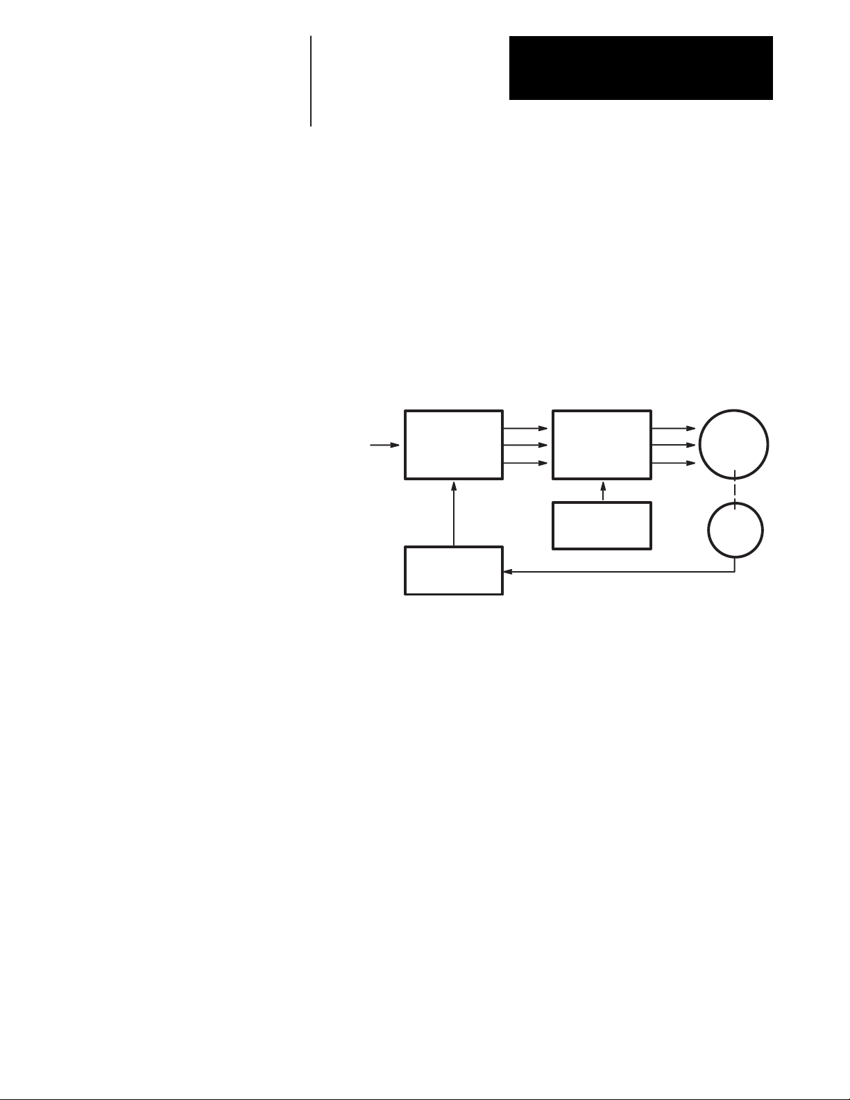
The three-phase relationship between the reference signal and the timing
wave provide a PWM wave to the power transistor base drive. This base
drive switches the power transistors across the 300V DC bus, providing
current to the motor windings, thus causing the motor to turn. A resolver
attached to the motor provides a signal corresponding to the actual rotor
position of the motor. This signal is decoded to a signal representing rotor
position and is fed to the commutation logic along with the torque
command. In this way, the controller combines the desired position signal
and current reference with the decoded resolver signal to produce a
reference signal commanding the controller to speed up or slow down. See
Figure 4.2.
Figure 4.2
Operation
Current
Referenc
e
Commutation
Logic &
Current Loop
Integrator
Position
Decoder
PWM
Generator &
Base Drive
Timing
Signal
Generator
Motor
Resolve
r
Shunt Regulator Operation The 1391B-ES shunt regulator provides power dissipation for regenerative
conditions when the energy returned to the controller by the motor exceeds
that which can be stored in the bus capacitors. The shunt regulator
monitors the bus voltage and at a predetermined “ON” point activates the
shunt regulator transistor, allowing current to flow through the shunt
resistor and dissipating power in the form of heat. A fuse is placed in series
with the resistor to protect it against short circuit conditions. When the
shunt transistor is activated and power is being dissipated at the resistor,
the bus voltage will quickly decrease, turning the transistor off when the
voltage reaches the “OFF” point. This cycle repeats, provided the bus
voltage continues to increase to the “ON” point. If too much regenerative
energy is present, the bus voltage will continue to increase even with the
shunt regulator on. At a predetermined bus voltage level, the 1391B-ES
will determine that an overvoltage condition exists, and trip out on an
Overvoltage Fault.
4-19
Page 22

Chapter 4
Description of Operation
The shunt regulator behavior is further modified by an adjustable duty
cycle timer. The timer is used to model the shunt resistor temperature.
SW1, a selector switch located on the top of the controller (see Figure 1.1)
determines the temperature level and therefore the average power level at
which the controller will trip out. When this level is reached, the controller
will be forced to trip out on an Overvoltage Fault. This action would be
equivalent to turning the shunt regulator off. Refer to Chapter 9 for further
shunt regulator information.
Logic Power Supply The 1391B-ES control logic voltage is ±12V DC and +5V DC. The
voltages are generated on the Power Driver Board, which receives its 36V
AC center-tapped input from a tertiary winding on the isolation
transformer.
Logic Control Boards The Logic Control Boards are the printed circuit boards that are readily
accessible behind the front cover of the controller. They contain all circuits
necessary to control the 1391B-ES. These circuits include: the velocity and
current loop, fault detection and annunciation circuits, power-up/powerdown logic, PWM generation and forward/reverse controlling circuits.
Figure 4.3
1391B-ES Block Diagram
4-20
Page 23

Chapter 4
Description of Operation
Fault Monitoring and Detection A number of Fault Monitor and Detection functions exist on the 1391B-ES
that guard the controller and help to minimize motor and system faults. The
occurrence of a fault will cause the controller to trip out. In this condition,
the Drive OK (DROK) contact will open and remain open until the fault is
cleared. If the DROK contact is wired into the user’s stop circuit, the
line/DB contactor (M) will also de-energize. This will place the shunt
resistor across the bus causing the motor to dynamic brake to a stop.
These fault conditions are annunciated through the front panel LED
indicators. The conditions displayed include:
Overtemperature
The controller contains a thermal switch on the heat sink which indirectly
senses transistor module temperature. If the temperature rating of the
switch is exceeded, the LED illuminates, the DROK contact opens and the
controller is disabled.
Power Fault
A fault related to the power bridge section of the controller will cause the
controller to be disabled, illuminate the LED and open the DROK contact.
Control (Power) Fault
If the control voltage varies more than ±10% of the nominal 12V DC or the
resolver wiring is grounded or missing, this fault will occur. When a fault
is detected, the LED illuminates, the DROK contact opens and the
controller is disabled.
Overvoltage
The DC power bus voltage is continuously monitored. If it exceeds a preset
level of 405V DC, the LED illuminates, the DROK contact opens and the
controller is disabled
Undervoltage
If the DC power bus voltage drops below 50% of its nominal operating
value, the LED illuminates and a signal will be present at TB2-13. A
switch setting on S2 selects the reaction of the DROK contacts to an
undervoltage detection. Two options are possible: 1) DROK opens, but
closes when the bus voltage is restored; 2) DROK is not affected by an
undervoltage.
Important: Regardless of interaction with the DROK contacts, the
transistor bridge is disabled upon an undervoltage condition. This is done
to protect the output transistors against voltage transients.
Current Foldback
The controller contains a fixed time versus current overload circuit which
monitors the current through each leg of the output bridge. If a fixed-time
versus current-product is exceeded, the LED is illuminated and a signal
will be present at TB2-14. This condition will reduce the current limit or
torque available to the motor.
Run/ Enable
The application of an enable signal by the machine position controller will
cause the RUN ENABLE LED to illuminate.
4-21
Page 24

Chapter 4
Description of Operation
Drive Ready
The status of the power supplies and fault conditions are monitored
continuously. If a fault is present, the DRIVE READY LED will not be
illuminated, a fault signal will be present at TB4 and the DROK contact
will be open.
Isolated Current Sensing The Logic Control Boards receive current feedback from the Isolated
Current Sense Board. This circuitry provides the data used for current
limiting and to modify bandwidth.
Integral Circuit Breaker The control logic and power circuitry are protected against overcurrents by
an integral circuit breaker. The DC bus supply and input rectifier utilizes a
three pole magnetic circuit breaker.
Line/DB Contactor The three-phase incoming AC line is opened by the contactor whenever the
Enable signal is removed or a fault occurs. This operation in conjunction
with the shunt regulator reduces the bus voltage when the contactor is
disabled. The Logic Control Board remains energized except when voltage
is removed from the incoming isolation transformer.
Important: The 1391B-ES contains a definite purpose contactor that is not
to be energized/de-energized more than twice an hour on a continuous
basis. The life of the contactor may be reduced considerably if the cycle is
exceeded. Contact your local Allen-Bradley Sales Representative for
additional information.
Power Driver Board The Power Driver Board contains the circuitry needed to switch the power
transistor modules.
A Quad B Board The A Quad B Board changes the resolver signal from a 1326AB or AD
motor into an encoder signal for use by a position controller.
Starting and Stopping
ATTENTION: The Enable control circuitry in the 1391B-ES
!
includes solid-state components. If hazards due to accidental
contact with moving machinery or unintentional flow of liquid,
gas or solids exist, an additional hardwired stop circuit may be
required. Refer to the codes and standards applicable to your
particular system for specific requirements and additional
information. A device that removes AC input power when a
stop is initiated is an integral part of this controller. Refer to the
following individual stop mode explanations.
4-22
Page 25

Chapter 4
Description of Operation
ATTENTION: The user has the ultimate responsibility to
!
determine which stopping method is best suited to the application and will meet applicable standards for operator safety.
Starting and Stopping must be accomplished by hardwired user supplied
elements as shown in Appendix B. Stopping modes for the 1391B-ES are
outlined below. Refer to the paragraphs that follow for detailed
information. The effects described below assume that the 36V AC control
voltage has not been de-energized.
Cause Effect on Motor
De-energize Line/DB Contactor (M) Coil Dynamic Brake
Speed Command brought to Zero Regenerative Brake
Open Enable Input Regenerative Brake
DROK Opens (Fault) Coast to Stop
Dynamic Braking
When the line/DB contactor (M) is de-energized by the control circuitry, an
inherent dynamic braking effect will occur during the DC bus decay,
provided the 36V AC logic voltage is not de-energized. The dynamic
braking effect depends on the value of the shunt regulator resistor and total
load inertia.
Important: Frequent cycling of the line/DB contactor to start/stop the
motor will reduce the life of the contactor. Refer to the paragraph that
follows.
Regenerative Braking
Normal run commands to the controller are performed through the Enable
input and any additional customer supplied control circuitry. Refer to
Appendix B. With input power applied, a mechanical contact closure
between TB2-9 & 10 or solid-state contact closure (open collector, +15 to
+30V DC) between TB2-10 & 12 will cause the controller to run, provided
the line/DB contactor (M) has been energized by the control circuitry.
When the Enable input is de-energized, the maximum available reverse
torque is applied to the motor in a regenerative stopping mode, which will
occur for approximately 450ms.
Coast
An internal controller fault opens the DROK contact. Coasting will only
occur if the DROK contact is not wired to the line/DB contactor coil (M) or
the Enable input circuits.
4-23
Page 26

Chapter 4
Description of Operation
Power-Up/Down Sequence Figure 4.4 describes the various steps involved in the power-up/down
sequence of the 1391B-ES controller.
Figure 4.4
Controller Power-Up / Down Sequence
POWER-UP
SEQUENCE
Application of 240V AC to Isolation
Transformer
a) Logic power supplies and base drive circuits
power-up.
b) Apply 115V AC to contactor.
c) Power bus charges.
d) If no faults are encountered, the DROK relay
energizes. Controller is ready to receive
customer enable signal.
Enable Signal Applied
Minimum of 100 ms after Contactor is Closed
a) Base drive enabled and will respond to
customer command inputs.
Enable Signal is Applied Prior to 36V AC
Power
a) When 36V AC power is applied, fault circuits
detect that the enable signal is already applied.
Random fault conditions occur.
b) Re-application of enable after resetting the
controller and with 36V AC power still
present, will energize the controller.
Fault
Fault
Fault
Fault
Fault
POWER-DOWN
SEQUENCE
Enable Signal Removed
a) Motor will regenerate to a stop.
b) Output power stage is disabled.
c) DROK relay maintains a no fault status.
240V AC Power Removed
a) Logic and DC link power supplies begin
decaying to zero volts.
b) Undervoltage (fault) condition occurs.
4-24
Fault Condition Occurs
a) Controller output stage disabled.
b) DROK relay is de-energized and a fault is
latched.
c) If contactor is wired to the DROK relay in a
stop string, contactor will open and the shunt
regulator will discharge the power bus
supply.
Page 27

End of Chapter
Chapter 4
Description of Operation
4-25
Page 28

Chapter
5
Inputs, Outputs and Adjustments
Chapter Objectives Chapter 5 contains descriptions of the various inputs and outputs available
on the 1391B-ES Servo Controller. Additionally, a comprehensive listing
and description of the potentiometer and switch adjustments is provided. In
some cases adjustment methods are provided for use during start-up. This
information is provided to help you understand some of the important
aspects about the controller prior to the actual installation and start-up. For
information on shunt regulator adjustments, refer to Chapter 9.
Inputs/Outputs The following paragraphs provide detailed descriptions of the various
inputs and outputs available for the 1391B-ES. See Figure 5.2 for terminal
block locations.
Terminal Block - TB1
Resolver Signals (TB1, Terminals 1-10)
These terminals are used for connection to the resolver. Refer to Appendix
B for connection details.
Terminal Block - TB2
Velocity Command Input (TB2, Terminals 1, 2)
The controller will accept up to a ±10V DC velocity command signal to
achieve maximum motor speed. The plus (+) and minus (–) reference are at
terminals 2 and 1, respectively. Shield must be terminated at source end
only. The differential impedance of the velocity command input is 40k
ohms (20k ohms for single ended inputs).
Signal Common (TB2, Terminals 3, 6, 12, 17)
Signal input reference point.
5-26
Buffered Output (TB2, Terminal 4)
This output is the differentially isolated velocity or torque command
applied at terminals 1 and 2 of TB2. It can be wired to the torque command
input (TB2-15 and 16) for torque block operation.
Page 29

Chapter 5
Inputs, Outputs and Adjustments
Adjustable Current Limit (TB2, Terminal 5)
The current limit of the controller is set to 300% or twice the continuous
rating of the controller, whichever is lower. Connecting this terminal to
Signal Common will enable potentiometer R148. The range of this pot is
20 to 300% or twice the continuous rating of the controller, whichever is
lower. This is used for feed to hard stop applications. When the workpiece
activates this condition through a limit switch or other user supplied
device, the current will be limited to the value set by R148, protecting the
motor against possible overheating.
Tachometer Output (TB2, Terminal 7)
A voltage corresponding to the motor velocity and direction of rotation will
be present between this terminal and Signal Common. With switch S2-1
(see the section entitled Switch Settings) set to “ON,” a voltage of ±1.2V
DC/1000 rpm will be present. With the switch in the “OFF” position, a
voltage of ±2.0V DC/1000 rpm will be present.
I Command Output (TB2, Terminal 8)
The voltage present between this terminal and Signal Common
corresponds to the motor current. A voltage of ±3.0V DC equals the rated
motor current as set by switch S1.
Enable Input (TB2, Terminals 9, 10)
Normal Run commands to the controller are performed through the Enable
input and any additional user supplied run control circuitry. With input
power applied and the line contactor energized, a solid-state contact closure
(rated +15 to +30V DC, 30 mA) between TB2-10 & 12 or a mechanical
contact closure between TB2-9 & 10 will cause the controller to run. When
this input is de-energized, the control will cause a regenerative braking
action in the motor.
Reset (TB2, Terminal 11)
Removing the Enable signal and momentarily connecting this terminal to
Signal Common will reset the controller after a controller fault occurs.
Important: A Reset must
not be initiated until the cause is determined and
corrected.
Low Bus (TB2, Terminal 13)
This terminal provides an open collector output rated at 12V DC, 5mA to
indicate a low bus voltage condition. Reference to Signal Common.
Current Foldback (TB2, Terminal 14)
This terminal provides an open collector output rated at 12V DC, 5mA to
indicate that current foldback is in operation. Reference to Signal
Common.
5-27
Page 30

Chapter 5
Inputs, Outputs and Adjustments
Torque Command Input (TB2, Terminals 15, 16)
Terminals 15 and 16 provide a small amount of input filtering for operating
the controller in a torque block or velocity feedforward mode. A ±3V DC
command equals 100% of the S1 current setting (i.e. motor rated current).
The buffered output of the command at terminal 4 of TB2 can be
connected to terminal 16 if more filtering is desired.
Spares (TB2, Terminals 18-20)
Reserved for future use and are not to be used.
Terminal Block - TB3 (A Quad B Board)
Figure 5.1 provides interconnect information between the position
controller and TB3 on the A Quad B Board.
ATTENTION: To guard against possible damage to the A
!
Quad B Board, assure that wiring between TB3 and the position
controller is correct. Refer to Figure 5.1.
Figure 5.1
A Quad B Board Wiring
A Quad B Board
1 TB2 20
21S3
987654321
Power
Supply
Input
Important: Note terminal orientation prior to wiring.
1
Recommended Wire – Belden #9728 or equivalent. Maximum distance between the A Quad B
Board and the position controller is 40 feet (12.2 meters) using a 5 volt signal. For distances up
to 300 feet (91 meters), 18 AWG (0.8 mm
2
For proper operation when interconnecting to IMC products, the B and B (NOT) signals must be
reversed.
When interfacing to IMC 121 or 123 controllers, use the 1391-CAQB cable.
Top Logic Control Board
10 TB3 1
To Position
1
Controller
2
) wire and an 8 to 15V DC power supply must be used.
1
TB3
Number
1
2
3
4
5
6
7
8
9
10
Description
A
A (NOT)
2
B
B (NOT)
Z
Z (NOT)
+5V DC (
Signal Common
+8 to +15V DC
In
No Connection
2
± 5%)
The A Quad B option operates in the same manner as the Allen-Bradley
845H Line Driver Encoder (26LS31 line driver output). The option
requires either a regulated +5V DC at terminal 7 or an unregulated +8 to
+15V DC input at terminal 9 (board draws 125mA maximum). The pulse
train output is selectable to 256, 512, 1024 or 2048 lines per revolution via
the Encoder Output switch, S3 (see page 5-36).
5-28
Page 31

Chapter 5
Inputs, Outputs and Adjustments
Terminal Block - TB4
Drive OK (DROK) Contacts (TB4, Terminals 17, 18)
Application of power to the transformer energizes the logic supply of the
controller. When 90% of rated DC Bus voltage is achieved and no
controller faults are detected, this relay contact is closed. The contact
remains closed until a controller fault occurs or power is removed from the
transformer. Contact rating: 115V AC, 1A or 24V DC, 0.3A. Refer to
Switch Settings – Drive OK/Drive Ready on page 5-35 for further
information.
36V AC Logic Supply Voltage (TB4, Terminals 19, 20, 21)
The isolation transformer contains four separate windings. Each winding
supplies 36V AC with a center tap. The 36V AC leads are brought out to
terminals 19 and 21 of TB4. The center tap must be connected to terminal
20 of TB4. See Chapter 9 for transformer details.
Terminal Block - TB5
Motor Power Terminals (TB5, Terminals 1, 2, 3)
Motor power is provided at these terminals. Refer to Chapter 6 and
Appendix B for connection details.
Input Power Terminals (TB5, Terminals 4, 5, 6)
The controller requires a 230V AC, three-phase, 50 or 60 Hz input supplied
by the transformer secondary. Refer to Chapters 6, 9 and Appendix B for
wiring and transformer information.
External Shunt Regulator Resistor (TB5, Terminals 8, 9, 10)
The 22.5A controllers have provisions to accept an external shunt resistor
to supplement the integral unit. This is available for applications that
require the dissipation of more regenerative energy to the DC Bus. To use
an external shunt resistor, first remove the jumper at terminals 8 and 10 of
TB5. Consult the Allen-Bradley sales office for application assistance.
The shunt regulator resistor supplied with the 1391B-ESAA45 must be
externally mounted and connected to terminals 8 and 9 of TB5 prior to
operation. Refer to Chapter 9 and Appendix B for details.
5-29
Page 32

Chapter 5
Inputs, Outputs and Adjustments
Figure 5.2
Terminal Block, Potentiometer and Switch Locations
Resolver Signals
TB1
110
Adjustable Current Limit
Gain
Scale
R132
R148
R144
S1
S2
ON
OFF
112
R1
DS1
DS2
DS3
DS4
DS5
DS6
DS7
DS8
Current Feedback
Scaling Switch
Configuration Switch
Offset
Overtemperature (red)
Power Factor (red)
Control Power (red)
Overvoltage (red)
Undervoltage (yellow)
Current Foldback (yellow)
Run Enable (green)
Drive Ready (green)
5-30
120
TB2
I/O Signals
Page 33

Chapter 5
Inputs, Outputs and Adjustments
Potentiometer Adjustments Preliminary adjustment of the Logic Control Board potentiometers is
required as explained below. Descriptions of the potentiometers follow.
Initially the potentiometers shall be set as shown in Table 5.A. See
Figure 5.2 for potentiometer locations.
T able 5.A
Initial Potentiometer Settings
Potentiometer
Current Limit (R148)
Velocity Gain (R144)
Offset (R1) and Scale
(R132)
Setting
10
4
Leave at the present setting until adjustment
becomes necessary in the Start-Up Procedure.
Current Limit (R148)
This single turn potentiometer adjusts the maximum current available to
the servomotor when TB2-5 is grounded. The maximum setting is 300% of
the motor rating or twice the continuous rating of the controller, whichever
is lower. The pot can be calibrated (fine tuned) using TP21 and the
proportion: 3V DC=100% continuous motor current.
Velocity Gain (R144)
This potentiometer is used to fine tune the response characteristics of the
system. Clockwise rotation increases the dynamic gain of the servo
amplifier, while counterclockwise rotation decreases gain. When used in
conjunction with the integral gain switch, the system response can be
adjusted over a wide range.
Offset (R1)
Adjustment for the system offset voltages is provided by this multi-turn
pot.
Velocity Command Scale (R132)
This adjustment is a multi-turn pot that scales the command signal with the
velocity feedback signal.
5-31
Page 34

Chapter 5
Inputs, Outputs and Adjustments
Switch Settings This section provides information on setting the Duty Cycle Selector
switch (SW1), Current Scaling switch (S1), configuration switches (S2)
and the A Quad B Encoder Output switch (S3). Refer to Figure 5.2 for
switch locations. Note that the settings for 1326AP motors are the same as
1326AB motors.
Duty Cycle Selector Switch - SW1
The Duty Cycle Selector Switch (SW1) which is located on top of the
controller, modifies the behavior of the shunt regulator. The switch
determines the temperature level and therefore the average power level at
which the controller will fault. Refer to Chapter 9 for detailed switch
setting information.
Current Feedback Scaling Switch - S1
The 1391B-ES employs a current feedback scaling circuit which allows a
controller to be used with 1326 AC Servomotors having lower current
ratings.
Tables 5.B and C provide the information necessary to correctly set the
current feedback scaling using switch S1. Table 5.B provides general
information on switch settings for typical motor / controller combinations.
Table 5.C provides examples of switch settings for specific 1326 AC
Servomotors. Refer to the motor nameplate for actual rated current (I
is
C
continuous current rating in amperes).
Important: The motor and controller rated current (as listed on their
respective nameplates) should be noted and the correct adjustment of
switch S1 made prior to applying power to the system.
Set S1 to a position equal or nearest to the rated motor current. One setting
higher must be used if the motor current is between current ratings. Once
the current feedback scaling is set, the current limit and peak current
capabilities will be a function of the motor current rating and not the
controller current rating.
5-32
Page 35

T able 5.B
T ypical Current Feedback Scaling
Motor Rated
1391B-ESAA1
5
15.0
14.1
13.1
12.2
11.3
10.3
9.4
8.4
7.5
6.6
5.6
4.7
3.8
2.8
1.9
0.9
Current
1391B-ESAA2
2
22.5
21.1
19.7
18.3
16.9
15.5
14.0
12.6
11.3
9.8
8.5
7.0
5.7
4.2
2.8
1.4
Chapter 5
Inputs, Outputs and Adjustments
1391B-ESAA4
5
45.0
42.2
39.4
36.6
33.8
30.9
28.1
25.3
22.5
19.7
16.9
14.1
11.3
8.4
5.6
2.8
S1 Switch Setting
F
E
D
C
B
A
9
8
7
6
5
4
3
2
1
0
T able 5.C
T ypical Scaling for 1326 AC Servomotors
Motor Catalog
Number
1326AB-A1E
1326AB-A2E
1326AB-A3E
1326AB-B1C
1326AB-B1E
1326AB-B2C
1326AB-B2E
1326AB-B3C
1326AB-B3E
1326AB-B4E
1326AB-C1C
1326AB-C1E
1326AB-C2C
1326AB-C2E
1326AB-C3C
1326AB-C3E
1326AB-C4B
1326AB-C4C
1326AD-K2G
1326AD-K3G
1326AD-K4F
1326AD-K5E
2
I
C
2.6
5.2
7.8
5.7
8.2
11.4
16.4
(A)
1391B-ESAA1
5
2
5
8
6
8
C
17.0
24.6
35.7
11.7
16.6
C
23.3
33.2
34.4
49.1
38.2
46.6
4.8
4.9
4.9
4.8
5
5
5
5
1
For reference only. Refer to motor nameplate for rated current value.
2
Settings for 1326AP and 1326AB AC motors are identical. If using blower, increase the motor
rated current by 35% and set S1 accordingly.
S1 Switch Setting
1391B-ESAA2
2
1
3
5
4
5
8
B
C
8
B
3
3
3
3
1
1391B-ESAA4
5
5
6
8
C
5
8
B
C
F
D
F
5-33
Page 36

Chapter 5
Inputs, Outputs and Adjustments
Configuration Switch - S2
Prior to start-up, the switch positions of S2 must be checked against the
listing in Table 5.D to ensure proper setting. Refer to the paragraphs
following the table for switch descriptions.
ATTENTION: Only personnel familiar with the 1391B-ES
!
controller and its associated machinery should plan or
implement the adjustment, calibration, start-up and subsequent
maintenance of the controller. Failure to comply may result in
personal injury and/or equipment damage.
ATTENTION: An incorrectly applied or calibrated controller
!
can result in component damage or a reduction in product life.
Wiring or application errors, such as, undersizing the motor,
incorrect or inadequate AC supply, or excessive ambient
temperatures may result in malfunction of the controller.
Switch
S2-1
S2-2
S2-3
S2-4
S2-5
S2-6
S2-7, 8
S2-9, 10
S2-11, 12
Function
Tachometer Scaling
Cut In
I
D
Magnitude
I
D
Drive OK / Drive
Ready
Torque Block / Velocity Loop Operation
Velocity Loop
Compensation
Error Amp Gain
Tachometer Filter
Staircase Filtering
T able 5.D
S2 Switch Descriptions (* Denotes factory setting for 1326AB motors)
Description/Setting
ON 1.2V / krpm 1326AB-Axx and 1326AD motors
OFF 2.0 / krpm 1326AB-Bxx & 1326AB-Cxx motors up to 4000 rpm*
See Table 5.E
ON 1326AB motors*
OFF 1326AD motors
ON DROK closes if no faults are detected and the bus voltage is up*
OFF DROK closes if no faults are detected, with or without bus voltage
ON Torque block operation
OFF Velocity loop operation*
ON Reduces integral gain (bandwidth) for high inertia systems
OFF Normal gain*
Reduces velocity loop gain when running 1326AD motors
S2-7
OFF OFF None*
OFF ON 33%
ON OFF 33%
ON ON 50%
Additional filtering in tach feedback circuit for mechanical resonances, etc.
S2-9
OFF OFF 430 Hz*
OFF ON 284 Hz
ON OFF 204 Hz
ON ON 165 Hz
Introduces additional filtering to the velocity command from positioning controller to
minimize staircasing effects from the DAC output
S2-11
OFF OFF – *
OFF ON 159 Hz
ON OFF 159 Hz
ON ON 79 Hz
S2-8 Gain Reduction
S2-10 Filter Bandwidth
S2-12 Filter Bandwidth
5-34
Page 37

Chapter 5
Inputs, Outputs and Adjustments
Tachometer Scaling (S2-1)
Switch S2-1 is used to configure the 1391B-ES tachometer synthesis
circuitry to a range appropriate for the applied motors. Select the “ON”
position for 1326AD and 1326AB-Axx motors and speeds to 6000 rpm.
“OFF” is used for 1326AB-Bxx and Cxx motors to 4000 rpm.
ID Cut In (S2-2)
This switch sets the ID cut in speed. ID is a phase specific current added to
the torque producing current at higher speeds to extend the performance
range of the controller. The ID point differs with the motor used. Refer to
Table 5.E for switch settings. For motors not listed, consult your
Allen-Bradley Sales Representative.
T able 5.E
S2-2 Switch Positions
Motor Catalog
Number
1326AB-A1E
1326AB-A2E
1326AB-A3E
1326AB-B1C
1326AB-B1E
1326AB-B2C
1326AB-B2E
1326AB-B3C
1326AB-B3E
1326AB-B4E
1326AB-C1C
1326AB-C1E
1
1
Settings for 1326AP and 1326AB AC motors are identical. If using blower, increase the motor
rated current by 35% and set S1 accordingly.
S2-2 Switch
Setting
ON
ON
ON
OFF
ON
OFF
ON
OFF
ON
OFF
ON
Motor Catalog
Number
1326AB-C2C
1326AB-C2E
1326AB-C3C
1326AB-C3E
1326AB-C4B
1326AB-C4C
1326AD-K2G
1326AD-K3G
1326AD-K4F
1326AD-K5E
1
S2-2 Switch
Setting
OFF
ON
OFF
ON
OFF
OFF
OFF
OFF
OFF
OFF
ID Magnitude (S2-3)
This switch is used to identify the type of motor being used. Set the switch
to “ON” to signify a 1326AB motor and “OFF” for a 1326AD motor.
Drive OK/Drive Ready (S2-4)
This switch causes the DROK contacts to close under different
circumstances.
If the switch is set to “ON,” the contact will close if no faults are detected
and the bus voltage is nominal. An undervoltage condition will cause the
DROK contacts to open.
If the switch is placed to the “OFF” position, the contacts will close once
the undervoltage condition clears. Bus undervoltage will not effect the
DROK contacts.
5-35
Page 38

Chapter 5
Inputs, Outputs and Adjustments
Torque Block/Velocity Loop Operation (S2-5)
Switch S2-5 is used to disable the velocity error amplifier to configure the
controller for torque block operation. In torque block mode the controller
acts as a current amplifier producing current (torque) proportional to the
command present at terminals 15 and 16 of TB2. Note that the Command
Scale and Velocity Loop Gain potentiometers (R132 & R144) have no
effect in the torque block mode. Scaling for torque block is ±3V
Command=100% of the S1 Current Setting (i.e. motor rated current). Place
switch S2-5 to the “ON” position for torque block operation and “OFF” for
velocity loop operation.
Velocity Loop Compensation (S2-6)
This switch is used to compensate the velocity loop for applications with
higher load inertia. Position the switch to “ON” for high inertia
compensation. High inertia compensation will generally improve
performance on systems with load inertias greater than three times motor
rotor inertia, although the user may wish to evaluate the impact of this
compensation at slightly lower inertias.
Error Amp Gain (S2-7, 8)
1326AD motors require less gain on the velocity loop. Switches S2-7 and 8
reduce the gain by a fixed percentage. If both switches are “OFF,” there is
no gain reduction. If either switch is ON, the gain will be reduced by 33%.
If further gain reduction is required, both switches should be placed to
“ON,” which provides a 50% reduction.
Tachometer Filter (S2-9, 10)
If the motor/tach is operating in a mechanically noisy system, additional
tach filtering may be necessary. These switches offer four levels of
filtering. Filter bandwidth can be decreased from 430 Hz. to 165 Hz. using
the switch settings described in Table 5.D.
Staircase Filtering (S2-11, 12)
These switches provide additional filtering to minimize “staircasing” of the
DAC output from the position loop controller. Three levels of velocity
command filtering are available as shown in Table 5.D.
A Quad B Encoder Output Switch - S3
S3 selects the line count that will be output from the A Quad B Board.
5-36
ATTENTION: Incorrect setting of S3 can cause erratic and/or
!
improper machine motion which may result in personal injury
or equipment damage. Assure that switch S3 has been properly
set as shown in Figure 5.3.
Page 39

Figure 5.3
A Quad B Board Switch (S3) Settings
Chapter 5
Inputs, Outputs and Adjustments
– ON –
S3
21
2 Marker Pulses per
Revolution
CCW Rotation of Motor Shaft
(similar to Allen-Bradley
845H)
Line
Count/
Revolution
2048
1024
512
256
A (NOT)
B (NOT)
Z (NOT)
S3-2
Switch Setting
OFF
OFF
ON
ON
A
B
Z
S3-1
Switch Setting
OFF
ON
OFF
ON
When using the A Quad B option with Allen-Bradley IMC motion
controllers, the AMP parameters will be set according to the line count
selected. In general, one parameter must be justified when using this
device. The normal line counts per cycle of the encoder must be divided
by two since the controller will see two markers per cycle.
Example (using an IMC 120 Controller)
With switch S3 set to 1024 lines per revolution (S3-2 OFF, S3-1 ON), the
lines per cycle of the position feedback device (located in the Feedback
Parameters File) must be 2048.
1024 x 4 = 4096 / 2 = 2048
Lines/Revolutio
n
(Quadrature)
2
Markers/Revolution
5-37
Page 40

Chapter
6
Installation
Chapter Objectives Chapter 6 provides the information needed to mount and wire the
1391B-ES Servo Controller for operation. Since most start-up difficulties
are the result of incorrect wiring, every precaution must be taken to assure
that the wiring is done as instructed. All items must be read and
thoroughly understood before the actual installation begins.
ATTENTION: The following information is merely a guide for
!
proper installation. The National Electrical Code and any other
governing regional or local code will overrule this information.
The Allen-Bradley Company cannot assume responsibility for
the compliance or the noncompliance to any code, national,
local or otherwise for the proper installation of this controller or
associated equipment. A hazard of personal injury and/or
equipment damage exists if codes are ignored during
installation.
Mounting Mounting dimensions for the 1391B-ES Servo Controller can be found in
Appendix A. Chapter 2 provides information on power dissipation and
environmental specifications. The controller must be located on a flat,
rigid, vertical surface and must not be subjected to shock, vibration,
moisture, oil mist, dust, corrosive vapors, etc. or temperatures that exceed
60° C (140° F) ambient.
Controllers can be mounted adjacent to each other with a minimum
clearance of 0.312” (7.9mm) between units and/or surrounding cabinetry
and non-current carrying surfaces. However, it is recommended that a
space of approximately 1.0” (25.4mm) be left between adjacent units to
allow easy access and removal of the front cover. To allow for proper
airflow, a minimum clearance of 3.0” (76.2mm) is required along the top
and bottom of the unit and any adjacent components.
The transformer that supplies 230V AC, three-phase and 36V AC to each
servo controller must have 3” (76.2mm) of clearance around it and any
adjacent components. This will allow for proper airflow and wiring access.
The transformer can be mounted in either a horizontal or vertical position.
6-38
Page 41

ATTENTION: The installation of the controller must be
!
Wiring Recommendations General Information
The information supplied in this manual on wire sizes, practices, layouts,
system configurations and grounding/shielding techniques for the
1391B-ES Servo Controller are presented as guidelines. Due to the
diversity of applications and systems, no single method of wiring is
completely applicable.
planned such that all cutting, drilling, tapping and welding can
be accomplished with the controller removed from the
enclosure. The controller is of the open type construction and
any metal debris must be kept from falling into it. Metal debris
or other foreign matter may become lodged in the circuitry
resulting in component damage.
Chapter 6
Installation
Important: This information represents common PWM servo system
wiring configurations, size and practices that have proven satisfactory in a
majority of applications. The National Electrical Code, local electrical
codes, special operating temperatures, duty cycles or system configurations
will take precedence over the values and methods listed.
Wire Sizes
Unless noted, the wire sizes in this manual are recommended minimums
and assume type MTW wire (machine tool wire, 75° C, minimum) per
NFPA 79. Since ambient conditions vary widely, on certain applications, a
derating factor has to be taken into account. Also, wiring to controllers or
motors exceeding 50 feet (15.2 meters) in length (total includes to and
from device) may cause excessive voltage drops. Consult the National
Electrical Code for factors on ambient conditions, length etc. or the
Allen-Bradley Sales Representative in your area for further information.
Shielding
Reasonable care must be taken when connecting and routing power and
signal wiring on a machine or system. Radiated noise from nearby relays
(relay coils should have surge suppressors), transformers, other electronic
drives, etc. may be induced into the velocity command signal lines causing
undesired movement of the servomotor.
6-39
Page 42

Chapter 6
Installation
To help alleviate the problem, machine power and signal lines must be
routed separately. The 1391B-ES power and signal lines must be shielded,
twisted and routed in separate ferrous metal conduit or harnesses spaced at
least 12” (304.8mm) apart. Power leads are defined here as the transformer
primary and secondary leads, motor leads and any 115V AC or above
control wiring for relays, fans, thermal protectors etc. Signal wiring is
defined as velocity command, resolver feedback, enable lines and low level
logic signal lines.
Feedback, command signal and other shields must be insulated from each
other and connected at a common machine or system earth ground in a
“star” fashion (i.e. all shields connected to a single earth ground point).
This helps to minimize radiated and induced noise problems and ground
loops. Refer to the paragraph entitled “Grounding” and Appendix B.
Open ended shields (resolver feedback cable at the resolver and velocity
command cable at the servo controller) must be insulated so that they do
not accidentally cause ground loops.
EMI Shielding
The 1391B-ES has an inverter carrier frequency of 2500 Hz. Therefore, the
system may induce noise into sensitive equipment lines adjacent to it.
ATTENTION: This controller can produce electromagnetic
!
Important: The thermal switch and brake wires are routed near motor
power and can pickup PWM radiation. Isolation from control devices may
be required.
Grounding
All equipment and components of a machine or process system shall have
their chassis connected to a common earth ground point. This ground
system provides a low impedance path that helps minimize shock hazards
to personnel and damage to equipment caused by short circuits, transient
overvoltages and accidental connection of energized conductors to the
equipment chassis.
radiation that may cause industrial or radio controlled
equipment to operate erratically and cause possible injury to
personnel.
The 1391B-ES system is designed to be interconnected with
Allen-Bradley EMI shielded motor cables only. Do
substitute cables. The EMI shield of the motor cable only, must
be grounded at both ends to function properly.
Not
6-40
Page 43

Wiring
Chapter 6
Installation
Grounding requirements, conventions and definitions are contained in the
National Electrical Code. Local codes will usually dictate what particular
rules and regulations are to be followed concerning system safety grounds.
See Appendix B.
ATTENTION: The National Electrical Code (NEC) and local
!
codes outline provisions for safely installing electrical
equipment. Installation must comply with specifications
regarding wire types, conductor sizes, branch circuit protection,
and disconnect devices. Failure to do so may result in personal
injury and/or equipment damage.
The Interconnect Drawing presented in Appendix B provides typical
interconnection wiring for the 1391B-ES AC Servo Controller. Typical
control logic circuitry (starting and stopping), motor interconnections and
grounding techniques are shown.
Motor Wiring
The motor wiring size is determined by the continuous and overload
current requirements (RMS Duty Cycle), NEC and local codes. In general,
motors operated from the following controllers would not require wire
sizes larger than those accepted by TB5, but codes must be followed. In
addition, the motor leads must be twisted throughout their entire length to
minimize radiated electrical noise. Allen-Bradley 1326 cables must be
used. The maximum motor wire sizes that the 1391B-ES controller will
accept are shown in Table 6.A.
T able 6.A
Maximum Motor Wire Sizes (TB5)
Controller Catalog
Number
1391B-ESAA15
1391B-ESAA22
1391B-ESAA45
Max. Wire Size
Accepted
2
#8 AWG (8.4 mm
MTW
#8 AWG (8.4 mm
MTW
#8 AWG (8.4 mm2) –
MTW
) –
2
) –
6-41
Page 44

Chapter 6
Installation
Motor Feedback Wiring
Connections to the integral commutation resolver must be made using an
Allen-Bradley 1326-CFUxx shielded cable.
ATTENTION: To guard against hazard of personal injury or
!
damage to equipment, the interconnections to the motor and
resolver must be made exactly as shown in Appendix B. Failure
to do so could cause loss of motor control and/or severe
oscillation of the motor shaft.
Encoder (A Quad B Board) Wiring
Recommended Wire – Belden #9728 or equivalent. Maximum distance
between the A Quad B Board and the position controller is 40 feet (12.2
meters) using a 5 volt signal. For distances up to 300 feet (91 meters), 18
AWG wire (0.8 mm
2
) and an 8 to 15V DC power supply must be used.
6-42
For proper operation when interconnecting to IMC products, the B and B
(NOT) signals must be reversed.
When interfacing to IMC 121 or 123 controllers, use the 1391-CAQB
cable. Refer to Chapter 5 for further information.
Transformer Wiring
The transformer secondary (230V AC, three-phase) connection to the
controller is phase insensitive and is shown in Appendix B. The maximum
wire size TB5 will accept is 8 AWG (8.4 mm
2
). Refer to Chapter 9 for the
transformer wiring diagrams.
The minimum recommended wire sizes for the transformer secondary are
listed below.
T able 6.B
Minimum Transformer Wire Sizes
kVA
Input Voltage
208V AC
240V AC
380V AC
415V AC
480V AC
575V AC
1.5
#12 (3.3)
#12 (3.3)
#12 (3.3)
#12 (3.3)
#12 (3.3)
#12 (3.3)
Important: All wire sizes are AWG (mm2). The transformer primary
requires protection by means of a customer supplied branch circuit
disconnect device. Refer to Appendix B.
3.5
#12
(3.3)
#12
(3.3)
#12
(3.3)
#12
(3.3)
#12
(3.3)
#12
(3.3)
5.0
#12
(3.3)
#12
(3.3)
#12
(3.3)
#12
(3.3)
#12
(3.3)
#12
(3.3)
10.0
#8 (8.4)
#8 (8.4)
#10
(5.3)
#12
(3.3)
#12
(3.3)
#12
(3.3)
12.5
#8 (8.4)
#8 (8.4)
#10
(5.3)
#10
(5.3)
#10
(5.3)
#12
(3.3)
15.0
#6 (8.4)
#8 (8.4)
#8 (8.4)
#10 (5.3)
#10 (5.3)
#10 (5.3)
Page 45

Chapter 6
Installation
Fusing (Transformer Primary)
Time delay fusing similar to Bussman Fusetron FRS Series or equivalent
must be used if the primary circuit is fused. Circuit breakers must provide
equivalent operation.
Fuse ratings shown in Table 6.C are the highest ratings allowed in a 25° C
(77° F) ambient temperature. Higher electrical enclosure ambient
temperatures will require fuses with higher current ratings. Consult fuse
manufacturer’s derating data. Fuses larger than those listed below may
result in transformer damage.
T able 6.C
Fuse Current Rating (A)
kVA
Primary Voltage
208V AC
240V AC
380V AC
415V AC
480V AC
575V AC
1.5
8
7
4.5
4
3.5
3
3.5
17.5
15
9
8
7
6
5.0
20
20
12
12
10
8
10.0
40
35
25
20
17.5
15
12.5
50
45
30
25
25
20
15.0
60
50
35
30
30
25
External Shunt Regulator Resistor
The external Shunt Regulator Resistor and fuse for the 45A 1391B-ES
must be connected to TB5-8 and TB5-9 as described in Chapter 9.
22.5A controllers must be converted for use with an external shunt resistor
and fuse. Refer to Chapter 9 for detailed instructions.
Interface Connections
Refer to Chapter 5 and Appendix B for connection information.
Motor Option Wiring
Wiring information is provided in Chapter 8 for the Blower Mod and Brake
Power Supply kits.
6-43
Page 46

Chapter
7
Start-Up
Chapter Objectives Chapter 7 provides the steps needed to properly start-up the 1391B-ES AC
Servo Controller. Included in the procedure are typical adjustments and
voltage checks to assure proper operation.
Start-Up Procedure The following procedure provides the required steps to start-up the
1391B-ES AC Servo Controller in velocity and position mode.
ATTENTION: Power must be applied to the controller to
!
!
perform many of the adjustments specified in the following
paragraphs. Voltages behind the front panel are at incoming line
potential. To avoid injury to personnel and/or damage to
equipment, only qualified service personnel should perform the
following start-up procedures. Thoroughly read and understand
the following procedure before beginning the Start-Up
Procedure. If an event does not occur while performing this
start-up, Do Not Proceed. Remove Power by opening the branch
circuit disconnect device and correct the malfunction before
continuing.
ATTENTION: This product contains stored energy devices. To
avoid hazard of electrical shock, verify that all voltage on the
capacitors has been discharged before attempting to service,
repair or remove this unit.
Voltage at terminals 9 (+) and 7 (–) of TB5 must be “0.00” as
measured with a standard digital voltmeter or multimeter.
Only qualified personnel familiar with solid-state control
equipment and safety procedures in publication NFPA 70E
should attempt this procedure.
7-44
o 1. Assure that all power to the controller is off. Most start-up
difficulties are the result of wiring errors. Therefore, prior to
applying power to the primary of the transformer or system, check
all of the system interconnection wiring.
o 2. Check terminal block connections as described in Chapter 5 and
Appendix B.
Page 47

Chapter 7
Start-Up
o 3. Assure that preliminary adjustment of the following items has been
performed:
- Potentiometer adjustments as described in Chapter 5.
- S1, S2 and SW1 switch settings as described in Chapter 5.
Important: The above adjustments must be performed before
proceeding.
o 4. Assure that the controller circuit breaker (MCB) OFF.
o 5. Apply power to the transformer, but Do Not enable the controller or
energize the line/DB contactor (M).
o 6. Using a voltmeter, verify that the voltages listed below are present at
the locations shown. The tolerance for all voltages is ±10%. Clear
faults before replacing any blown fuses.
Location Voltage
TB5-4 to TB5-5 230V AC
TB5-4 to TB5-6 230V AC
TB5-5 to TB5-6 230V AC
TB4-19 to TB4-20 18V AC
TB4-21 to TB4-20 18V AC
TB4-21 to TB4-19 36V AC
TP13 to TP12 +12V DC
TP14 to TP12 –12V DC
o 7. Remove all power to the transformer.
o 8. The wires connected to terminals 9 and 10 of TB2 must be marked
and removed to allow for local operation of the Enable circuit.
Connect a suitable temporary switch between these terminals and
insulate the switch connections. See Figure 7.1.
Figure 7.1
Local Control Connections
Variable
Command
Input
Battery
Box
+–
Temporary
Local Enable
Switch
1391B-ES
Controller
TB2-1
TB2-2
TB2-9
TB2-10
7-45
Page 48

Chapter 7
Start-Up
o 9. The wires connected to terminals 1 & 2 of TB2 (Velocity Command
Input) must be marked and removed. A ±10V DC local control
(battery box) is to be connected to these terminals. See Figure 7.1.
The polarity of the Command signal from the battery box should be
the same as the actual control source to assure correct motor rotation
when the controller is placed into operation as part of the system.
ATTENTION: Even though the Command SCALE
!
potentiometer is set to zero, the servomotor may begin to rotate
and cause incorrect machine movement when the controller is
enabled. Be prepared to remove controller power by opening
(MCB) or the branch circuit disconnect device if this occurs.
This movement may be due to a wiring error or system
component malfunction and must be corrected before
proceeding with this procedure. Damage to machine system
components can occur due to uncontrolled machine movements.
It is recommended that the motor be mechanically disconnected
from the load if:
A) Improper direction of rotation could cause damage to
equipment.
B) Uncontrolled motor rotation due to improper phasing will
cause damage to the equipment.
o 10. Once control connections are made:
a) Set Command input to zero at the battery box.
b) Open Enable switch.
c) Apply power to the transformer primary.
Place the circuit breaker (MCB) to the ON position. The green
DRIVE READY LED should illuminate.
Important: If power is applied while the controller is enabled, one
or more fault LED’s will illuminate and disable the controller. The
controller may be reset by removing the Enable signal and
momentarily grounding the Reset terminal (TB2-11). An alternate
method would be to remove and reapply the branch circuit or
controller power (36V CT) with the Enable input removed.
7-46
ATTENTION: In the following step, reverse rotation or
!
uncontrolled rotation at high speed can occur. To guard against
injury, read through the procedure before attempting to start the
motor.
Page 49

Chapter 7
Start-Up
o 11. If adjustable current limit is not desired, proceed to step 12. Ground
TB2-5 to TB2-6. Set Current Limit to zero. With a 10% Command
input signal applied to terminals 1 and 2 of TB2, momentarily close
the local Enable switch and observe motor speed and direction of
rotation. The motor should rotate slowly under control (following
the Command signal). If the motor is under control but rotating in
the wrong direction, reverse the command input signal polarity and
note the change on the machine interconnection drawing.
If the motor is uncontrollable, check the feedback wiring at the
controller and check for correct phasing of the motor leads. If this
does not correct the problem, the position feedback device may be
incorrectly phased. Check that the current feedback scaling is set
properly and slowly adjust the Current Limit potentiometer (R148)
to the maximum clockwise position.
o 12. Open the Enable switch and branch circuit disconnect.
o 13. Remove battery box and connect a jumper between terminals 1 and
2 of TB2. Apply power and close the Enable switch. Adjust the
Velocity Loop OFFSET potentiometer (R1) to obtain zero rotation
of the motor shaft.
o 14. Open the branch circuit disconnect. Remove jumper and reconnect
the wires removed in step 9. Reapply power.
o 15. On position controlled systems, the position loop gain (system
following error) should be set by adjusting the Velocity Command
SCALE potentiometer (R132) while commanding various moves
from the position controller to achieve desired following error.
On velocity controlled systems (no position loop), the Velocity
Command SCALE pot (R132) should be adjusted to give the desired
motor speed at the maximum command (reference) voltage.
o 16. If the proper position loop gain (following error adjustment) or
speed cannot be set at maximum motor speed, switch S2-6 may be
improperly set (see Chapter 5).
o 17. Important: Before performing this step, ensure that the GAIN pot is
set to “4” or below. A setting higher than “4” could cause the motor
to vibrate violently.
Adjust the Velocity GAIN potentiometer (R144) and set switch S2-6
as needed. The GAIN adjust pot is used to fine tune the servo
system response, switch S2-6 provides varying degrees of response.
Setting GAIN at position #4 and placing the switch to “OFF” will
give satisfactory response for most applications. If further
optimization of the system response is required, the System
Compensation Procedure should be followed. If optimization is not
required, proceed to step 20.
7-47
Page 50

Chapter 7
Start-Up
Commanded Velocity
Figure 7.2
Velocity Response Profiles
R144 Controls Amount of Overshoot
Underdamped
Critically Damped
Overdamped
Time
System Compensation Procedure
o 18. Monitor the velocity feedback signal at terminals 6 (common) and 7
of TB2 with an oscilloscope or chart recorder.
ATTENTION: If an oscilloscope (or chart recorder) is used
!
during Start-Up or Troubleshooting, it must be properly
grounded. The oscilloscope chassis may be at a potentially fatal
voltage if not properly grounded. Always connect the
oscilloscope chassis to earth ground.
When using an oscilloscope (or chart recorder) it is
recommended that the test probe ground be connected to TP12.
o 19. Adjust the Velocity GAIN potentiometer (R144) and observe the
velocity response (at TB2-7) profile at various levels of step input
speed commands. The “Underdamped” response curve in Figure 7.2
with a single velocity overshoot of 20-30% on accel and decel is
optimal on a point to point positioning or velocity controlled system.
The “Critically Damped” curve is desirable on a contouring or metal
removing system.
7-48
The GAIN pot should be adjusted so that the motor achieves the
commanded speed or final position as quickly as possible with no
overshoot. In addition to the dynamic response, the motor shaft
should not oscillate or exhibit any erratic motion at zero speed.
Page 51

Chapter 7
Start-Up
o 20. Remove power with the branch circuit disconnect.
o 21. Remove the local Enable switch and reconnect external wiring.
o 22. Apply power and check system operation.
o 23. Remove power with the branch circuit disconnect and if necessary,
reconnect motor to load.
7-49
Page 52

Chapter
8
The 1326 AC Servomotor
Chapter Objectives Chapter 8 describes the operation of a standard 1326 AC Servomotor with
the enhanced capabilities of a Bulletin 1391B-ES AC Servo Controller.
Refer to the 1326 AC Servomotor Product Data for further information on
Allen-Bradley AC Servomotors.
Introduction The 1391B-ES provides additional energy to the 1326 motor, allowing it to
operate at higher speeds without a reduction of torque.
In general, the 1326 motor will follow the speed–torque curve shown in
Figure 8.2
Figure 8.2
T ypical Bulletin 1326 Speed–Torque Curve
Peak Torque with
Nominal 15%
Low Input Line
Voltage
75%
(Tp)
Speed
(% rated rpm)
Rated Speed
100
90
80
70
60
50
40
30
20
10
0
0 20 40 60 80 100 120 140 160 180 200
70%
Peak Torque with
Nominal Input Line
Voltage
70%
(Tc)
Torque (% rated)
8-54
Rated
Operation
Intermittent
Operation
Tc – rated torque of motor with windings at rated temperature and an
ambient of 40°C. The controller is operating in a rated ambient of 60°C.
Page 53

Chapter 8
The 1326 AC Servomotor
Tp – the peak torque that can be produced by the motor/controller
combination with both at rated temperature and the motor in a 40°C
ambient and the controller in a 60°C ambient. Since 200% current torque
peaks are common in many applications for optimal controller usage, the
following curves show typical system performance. Higher peak torques
are permissible where RMS torque is less than or equal to the rated torque
(Tc). 1391B-ES operation is shown in the outer envelope and will show
higher speed and 300% torque capability.
Rated Speed – the operating speed of the controller and motor
combination at which a minimum of 70% of continuous rated torque (Tc)
can be developed. This point is defined with the motor at 25°C and
controller operating in a 60°C ambient.
Rated Operation Area – boundary of speed-torque curve where the motor
and controller combination may operate on a servo basis without exceeding
the RMS rating of either.
Duty Cycle Profile
RPM
t
4
Decelerat
e (Tpd)
3
Rest
(Tr)
t
4
2
Repeat
Accelerat
e (Tpa)
Total Cycle
Time
2
x t1 + Tss2 x t2 + Tpd2 x t3 + Tr
Trms =
where:
Trms The motors RMS or average torque over the duty cycle. (Expressed in
Tpa Motor peak torque to accelerate to maximum speed. (Expressed in lb.-in.
Tss Motor torque present at the motor shaft during constant speed segment.
Tpd Motor peak torque to decelerate to zero speed. (Expressed in lb.-in. or
Tr Torque when motor is at zero speed (typically is Tss).
, t2, t3, t4
t
1
Tpa
lb.-in. or lb.-ft. The same units must be used throughout the formula.)
or lb.-ft. The same units must be used throughout the formula.)
(Expressed in lb.-in. or lb.-ft. The same units must be used throughout the
formula.)
lb.-ft. The same units must be used throughout the formula.)
Time for each portion of the duty cycle in seconds.
t
1
t1 + t2 + t3 + t
Stead
y
Speed
(Tss)
t
2
Move
Cycle
x t
4
Intermittent Operation Area – Boundary of speed-torque curve where
the motor and controller combination may operate in acceleration-deceleration mode without exceeding peak rating of either, provided that the duty
cycle RMS continuous torque limit is not exceeded.
8-55
Page 54

Chapter 8
The 1326 AC Servomotor
Table 8.A provides a comparison of the resultant speed obtained from
standard Bulletin 1326 servomotors using Bulletin 1391 and Bulletin
1391B–ES Servo Controllers.
T able 8.B
1391/1391B-ES Speed Comparison
Continuous
Stall
Torque
(lb.-in./
N-m)
16/1.8
32/3.6
48/5.4
93.3/10.53
102/11.5
140/15.8
153/17.3
210/23.7
310/35.0
420/47.4
1
All ratings are for 40° C motor ambient,110° C case and 60° C amplifier ambient. For extended ratings at lower ambients contact Allen-Bradley.
420/47.4
2
The motor contains two thermal switches wired in series that will open on an overtemperature condition. They are set to open at 150° C (typical) and
close at 90-100° C (typical). Contacts are rated for 1A at 115V AC, 1A at 24V DC.
3
–10% line voltage maximum.
Peak Stall
Torque
(lb.-in./
N-m)
48/5.4
96/10.84
144/16.3
170.7/19.3
279/31.5
280/31.6
459/51.9
569/64.3
568/64.1
811/91.7
989/111.8
Rated
Speed
(rpm)
6000
4000
4000
4000
4000
4000
4000
4000
4000
3000
2000
Motor
Catalog Number
1326AB-A1G
1326AB-A2E
1326AB-A3E
1326AB-B2E
1326AB-B2E
1326AB-B3E
1326AB-B3E
1326AB-C2E
1326AB-C3E
1326AB-C4C
1326AB-C4B
Servo Amplifier
Catalog Number
1391B-AA15
1391B-AA15
1391B-AA15
1391B-AA15
1391B-AA22
1391B-AA22
1391B-AA45
1391B-AA45
1391B-AA45
1391B-AA45
1391B-AA45
Amperes
at
Continuous
Torque
4.5
5.2
7.8
15.0
16.4
22.5
24.6
33.2
49.1
46.6
38.2
Rotor
Inertia
(lb.-in.-s
2
/kg-m
)
0.004/0.0005
0.007/0.0008
0.010/0.001
0.05/0.006
0.05/0.006
0.08/0.009
0.08/0.009
0.14/0.015
0.22/0.024
0.29/0.032
0.29/0.032
2
Rated
Output
(kW)
0.9
1.1
1.6
3.0
3.3
4.7
5.1
6.9
10.0
3
9.3
7.5
Motor Options/Accessories For detailed motor option/accessory information, refer to the individual
instruction sheets shipped with the option/accessory.
8-56
Page 55

End of Chapter
Chapter 8
The 1326 AC Servomotor
8-57
Page 56

Chapter
9
Transformers and Shunt Regulators
Chapter Objectives Chapter 9 provides general information about the 1391 Isolation
Transformer. In addition, shunt regulator information is also provided.
1391 Transformers The 1391B-ES must operate from an isolation transformer having a
three-phase, 230V AC output and a single-phase, 36V AC output.
Transformers supplied with the 1391B-ES can provide power for up to four
controllers. Standard three-phase input voltages for the 60 Hz units are
available. The kVA values specified are the continuous outputs of the units
in a 60° C ambient.
Important: The maximum rating that can be connected to the 1391B-ES is
15 kVA.
Important: The 1391B-ES controller uses a phase sensitive 36V AC
transformer tap to provide power to the Logic Control Board. It is
recommended that a 1391 Isolation Transformer be used. Contact your
local Allen-Bradley Sales Representative if a transformer of a different
type must be used. Refer to Figure 9.1 and Appendix B for connection
information.
ATTENTION: Damage to the controller will result if the center
!
60 Hz Transformers
Two 60 Hz transformers are available and have input ratings of:
1. 240/480V AC , three-phase
2. 208/230/460/575V AC, three-phase
tap wire (Y2, Y5, Y8, Y11) shown in Figure 9.1 is not
connected to TB4-20 as shown in Appendix B.
9-54
Page 57

Chapter 9
Transformers and Shunt Regulators
50/60 Hz Transformers
The 50/60 Hz transformer that is available has an input rating of
240/380/415/480V AC, three-phase.
NEMA Type 1 Enclosure
Dimensions for the NEMA Type 1 enclosures are shown in Appendix A.
Important: The NEMA Type 1 enclosure is shipped as a kit for customer
assembly.
If other input voltages or special enclosures are required, consult your local
Allen-Bradley Sales Representative. Refer to Figure 9.1 for connection
information and Appendix A for dimensions.
9-55
Page 58

Chapter 9
Transformers and Shunt Regulators
Figure 9.1
1391 Transformer Wiring Diagrams
1391-TxxxDT
Primary
Voltage
240V AC
480V AC
Connect
H1 to H3 to H8
H2 to H4 to H6
H5 to H7 to H9
H2 to H3
H5 to H6
H8 to H9
Lines On
H1
H4
H7
H1
H4
H7
Faraday
Shield
G2
H1 H3 H2 H4 P1 P2 G0
G1
X1 X2 X3
X0
Primary
Voltage
240V AC
380V AC
415V AC
480V AC
H6 H5 H7 H9 H8
230V AC230V AC
230V AC
1391-TxxxET
Connect
H2 to H6
H7 to H11
H12 to H1
H3 to H6
H8 to H11
H13 to H1
H4 to H6
H9 to H11
H14 to H1
H5 to H6
H10 to H11
H15 to H1
Lines On
H1
H6
H11
Y1
36V AC
CT 200VA
Primary
Voltage
208V AC
240V AC
480V AC
575V AC
Thermal switch for transformer protection
(rated 115V AC/1A, 24V DC/0.25A min.,
185° C ±5° C)
Y2
Y3 Y4
Y5
Y6 Y7
36V AC
CT 200VA
Y8
36V AC
CT 200VA
1391-TxxxNT
Connect
H2 to H6
H7 to H11
H12 to H1
H3 to H6
H8 to H11
H13 to H1
H4 to H6
H9 to H11
H14 to H1
H5 to H6
H10 to H11
H15 to H1
Lines On
H1
H6
H11
Y9 Y10
36V AC
CT 200VA
Y11
Y12
Faraday
Shield
9-56
H6 H7 H8 H9 H10H1 H2 H3 H4 H5 H11 H12 H13 H14 H15 P1 P2 G1 G0
Thermal switch for transformer protection
(rated 115V AC, 1A, 24V DC/0.25A min.,
185° C ±5° C
X1 X2 X3
X0
230V AC
230V AC230V AC
Y2
Y1
Y3 Y4
36V AC
CT 200VA
Y5
Y6 Y7
36V AC
CT 200VA
Y8
Y9 Y10
36V AC
CT 200VA
Y11
Y12
36V AC
CT 200VA
Page 59

Chapter 9
Transformers and Shunt Regulators
Shunt Regulator Operation Refer to Chapter 4 for an explanation of the shunt regulator circuitry. The
nominal data for the shunt regulator is as follows:.
Overvoltage Trip Point = 405V DC±2.5%
DC Bus Shunt “ON” Point = 386.4V DC
DC Bus Shunt “OFF” Point = 366.9V DC
Nominal DC Bus Voltage = 300V DC
DC Bus Undervoltage Detect = 145V DC±20%
The shunt regulator behavior is modified by an adjustable duty cycle timer.
The timer is used to model the shunt resistor temperature. A selector switch
(SW1) determines the temperature level and therefore the average power
level at which the controller will fault. When this level is reached, the
controller will be forced to fault on an overvoltage. This action would be
equivalent to turning the shunt regulator off.
The Duty Cycle Selector Switch is located on top of the controller near
terminal Block, TB5 (see Figure 1.1). The switch has 16 positions
designated “0 to F,” with “0” being the lowest value and “F” the highest.
The higher the setting, the higher the average power seen by the shunt
resistor. The Duty Cycle Selector Switch settings for various
controller/shunt combinations are shown in Tables 9.A and B.
Important: Accurate operation of the Duty Cycle Timer is dependent on
the shunt resistor value. Do Not substitute alternate values.
Table 9.A provides the required Duty Cycle Selector Switch settings and
resistor power trip points for factory supplied configurations. An optional
external resistor assembly (catalog number 1391-MOD-SR22A) is
available for the 22.5A 1391B-ES.
T able 9.A
Maximum Switch Settings and Trip Points for Factory Supplied Configurations
Configuration
1391B-ESAA15 w/ standard 16 ohm internal resistor
1391B-ESAA22 w/ standard 12 ohm internal resistor
1391B-ESAA22 w/ 9 ohm external resistor
(1391-MOD-SR22A)
1391B-ESAA45 w/ standard 5 ohm external resistor
* Denotes SW1 setting at time of shipment. User must reconfigure controller when using optional
1391-MOD-SR22A.
SW1
Switch
Setting
B*
B*
F
D*
Nominal
Trip Point
164w, ±10%
162w, ±10%
386w, ±10%
715w, ±10%
ATTENTION: The designated settings for the factory supplied
!
configurations must be used or damage to the controller may
result.
9-57
Page 60

Chapter 9
Transformers and Shunt Regulators
Table 9.B shows the nominal resistor power trip levels in watts for the
various switch settings. When shunt requirements exceed the selector
setting, the excess power will cause the bus voltage to rise, resulting in an
overvoltage fault condition.
T able 9.B
Nominal Power Trip Level Reference Data (continuous watts,±10%)*
SW1
Switch
Setting
0
1
2
3
4
5
6
7
8
9
A
B
C
D
E
F
* Denotes the maximum allowable settings for factory supplied configurations.
15A
W/ Int. 16
Ohm Resistor
67
71
75
80
85
91
99
107
118
130
145
164*
189
223
272
347
22.5A
W/ Int. 12
Ohm Resistor
73
77
82
86
92
98
105
113
122
133
146
162*
183
208
242
290
22.5A
W/ Ext. 9
Ohm Resistor
98
103
109
115
122
130
139
150
163
177
195
216
243
277
323
386*
45A
W/ Ext. 5
Ohm Resistor
215
227
241
256
274
294
317
344
378
417
466
527
607
715*
872
1115
9-58
ATTENTION: To guard against personal injury and/or
!
equipment damage from an overheated resistor, the designated
duty cycle settings for factory supplied shunt resistor
configurations must not be exceeded. Check the Duty Cycle
Selector Switch (SW1) to ensure that it is set properly before
operation.
ATTENTION: When using a customer supplied external shunt
!
resistor assembly, the Duty Cycle Selector Switch (SW1) must
be set to an appropriate level for that resistor assembly. Consult
the resistor manufacturer for the appropriate derating
guidelines. Failure to comply could result in personal injury
and/or equipment damage from an overheated resistor.
Page 61

Frequent overvoltage trips on high inertia systems (load is 2 or 3 times the
motor inertia) during regenerative states (deceleration) may be an
indication that an external shunt resistor having increased power
dissipation capacity is required. Based on the data supplied, Allen-Bradley
will specify a shunt resistor with the proper resistance value for the
controller being used.
Shunt Regulator Installation External Shunt Resistors
The 1391B-ES is designed to allow the use of an external shunt resistor on
the 22.5 and 45A units. To use an external shunt resistor with the 22.5A
units, the user must reconfigure the controller at terminal block TB5.
The following steps provide the information needed to properly convert
22.5A controllers for use with an external shunt resistor and fuse. Refer to
the resistor and fuse mounting dimensions provided in Appendix A and the
Interconnect Diagram in Appendix B, as required.
Chapter 9
Transformers and Shunt Regulators
ATTENTION: To guard against an electrical shock hazard,
!
24. Remove and discard the jumper present between terminals 8 and 10 of
!
25. Connect one end of the new external shunt fuse to terminal 9 of TB5.
ensure that all power to the controller has been removed prior to
performing the following procedure and the bus voltage at
terminal 9 (+) and 7 (–) of TB5 measures 0.00 volts.
TB5. This disconnects the internal shunt resistor and fuse from the
shunt regulator circuit.
ATTENTION: When using an external shunt resistor assembly
with the 22.5A 1391B-ES, ensure that the internal resistor
assembly has been disconnected per the above instructions.
Personal injury and/or equipment damage could result from an
overheated resistor if the internal resistor is not disconnected.
Connect the other end of the fuse to one end of the shunt resistor.
Important: The external shunt resistor must have a fuse in series with
the shunt resistor. Refer to the paragraph entitled “Shunt Fusing” for
more information.
26. Connect the remaining end of the shunt resistor to terminal 8 of TB5.
27. Using Table 9.B, set the Duty Cycle Selector Switch to the appropriate
setting for the resistor being used.
28. Install the appropriate shunt fuse in its holder.
9-59
Page 62

Chapter 9
Transformers and Shunt Regulators
ATTENTION: Proper derating must be applied to the
!
manufacturers nominal resistor power ratings when using these
in external shunt configurations. Consult the resistor
manufacturer for recommended derating. Failure to comply
could result in personal injury and/or equipment damage from
an overheated resistor.
Shunt Fusing
Shunt regulator fusing is provided with all of the 1391B-ES controllers.
The fuse is in series with the resistor and used to protect the resistor against
short circuits. The shunt fuse is located on top of the controller near the
circuit breaker for 15 and 22.5A controllers. External resistors for 22.5A
and 45A controllers are supplied with a fuse which must be mounted
external to the controller (see Appendix A for mounting dimensions). Refer
to Table 9.C for further shunt fuse information.
T able 9.C
Shunt Fuse Information
Controller
Rating
15A
22.5A
22.5A
45A
Fuse Location
Top Panel
Top Panel
External
External
Fuse Type
Buss KLM-10 or equivalent
Buss FNM-6.25 or equivalent
Buss KTK-15 or equivalent
Buss KLM-20 or equivalent
Important: Repeated overvoltage tripping can be an indication that the
shunt fuse has malfunctioned.
9-60
Page 63

End of Chapter
Chapter 9
Transformers and Shunt Regulators
9-61
Page 64

Chapter
10
Troubleshooting
Chapter Objectives Chapter 10 provides information to guide the user in troubleshooting the
1391B-ES. Included in the chapter are LED descriptions and fault
diagnosis, general system troubleshooting and test point descriptions.
System Troubleshooting Most controller faults are annunciated by the LED diagnostic indicators on
the front of the controller. Many system malfunctions manifest themselves
through a controller fault. The use of LED indications may aid in
identifying servo controller and motor malfunctions.
Table 10.A provides a listing and description of the LED indicators. In
addition, potential causes are listed.
Tables 10.B and 10.C provide a number of common system and
servomotor malfunctions and their possible causes.
Table 10.D provides a listing and description of the 1391B-ES test points.
ATTENTION: This product contains stored energy devices. To
!
avoid hazard of electrical shock, verify that all voltage on the
capacitors has been discharged before attempting to service,
repair or remove this unit.
Voltage at terminals 9 (+) and 7 (–) of TB5 must be “0.00” as
measured with a standard digital voltmeter or multimeter.
Only qualified personnel familiar with solid-state control
equipment and safety procedures in publication NFPA 70E
should attempt this procedure.
10-62
Page 65

T able 10.A
LED Descriptions and Fault Diagnosis
Chapter 10
Troubleshooting
LED
OVERTEMPERATURE
(RED)
POWER FAULT
(RED)
CONTROL (POWER) FAULT
(RED)
OVERVOLTAGE
(RED)
UNDERVOLTAGE
(YELLOW)
LED Description
The controller contains a thermal
switch on the heat sink which
senses the power transistor
temperature. If the temperature is
exceeded the LED will illuminate.
The current through the power
output transistors is monitored. If
the current exceeds a fixed level
(greater than 300% of controller
rating) the LED will illuminate.
A fault will occur and the LED will
illuminate, if:
1. The logic supply rises or drops
10% from its nominal value
or
2. The resolver wiring is open or
shorted.
The DC Power Bus is continuously
monitored. If it exceeds a preset
level a fault is sensed, the power
supply is disabled and the LED is
illuminated.
If the DC Power Bus drops below a
preset level, a fault occurs and the
LED is illuminated.
Potential Cause
OVERTEMPERATURE LED is Illuminated
The logic supply (±12V DC, +5V DC) circuits have malfunctioned
(fuse blown etc.) or the AC input at TB4-19, 20, 21 is incorrectly wired.
The heat sink thermal overload has tripped. One or more of the
following may have occurred:
1. The cabinet ambient temperature is above rating.
2. The machine duty cycle requires an RMS current exceeding the
continuous rating of the controller.
3. The integral fan is not functioning.
4. The airflow access to the controller is limited or blocked.
POWER FAULT LED is Illuminated
1. The current through any one of the power transistors has exceeded
300% of the controller’s current rating.
2. Malfunctioning power transistor.
3. Shorted Lead.
4. Winding to case motor capacitance is out of tolerance.
CONTROL (POWER) FAULT LED is illuminated
1. Open or short circuit on resolver wiring.
2. The input line voltage is out of tolerance.
2. The transformer auxiliary logic supply winding is open.
3. The logic supply (±12V DC, +5V DC) circuits have malfunctioned
(fuse blown etc.) or the AC input at TB4-19, 20, 21 is incorrectly
wired.
OVERVOLTAGE LED is illuminated
The logic supply (±12V DC, +5V DC) circuits have malfunctioned
(fuse blown etc.) or the AC input at TB4-19, 20, 21 is incorrectly wired.
The power bus voltage has exceeded 405V DC.
1. Logic Board is malfunctioning and incorrectly sensing the bus
voltage.
2. A vertical axis with insufficient counterbalancing is overdriving the
servomotor and causing excessive energy to be returned to the power
supply bus.
3. The system inertia is too high causing excessive energy to be
returned to the power supply bus.
4. Input line voltage exceeds the maximum controller input voltage
rating.
5. The position controller acceleration / deceleration rate is incorrectly
set.
6. The shunt regulator or transistor has malfunctioned.
UNDERVOLTAGE LED is illuminated
7. Shunt regulator fuse has blown.
8. Shunt regulator resistor not connected to controller.
The power bus voltage has dropped below a preset DC value
1. The power contactor (M) has not energized or has dropped out.
2. The input line voltage is low.
3. The shunt regulator circuit has malfunctioned and is placing the
shunt resistor across the power bus.
4. The power bus capacitor has malfunctioned.
5. The circuit breaker (MCB) has tripped.
6. The three-phase input line is open.
7. Transformer is supplying the wrong line voltage or has
malfunctioned.
10-63
Page 66

Chapter 10
Troubleshooting
Table 10.A
LED Descriptions and Fault Diagnosis (Continued)
LED
UNDERVOLTAGE
(Continued)
CURRENT FOLDBACK
(YELLOW)
RUN ENABLE
(GREEN)
LED Description
The CURRENT FOLDBACK
LED illuminates when the
Current Foldback circuitry is
operating.
The application of an Enable
signal by the machine position
controller will cause the RUN
ENABLE LED to illuminate.
Potential Cause
The logic supplies have dropped 10% below their nominal value
1. The input line voltage is out of tolerance.
2. The transformer auxiliary logic supply winding is open.
3. The logic supply (±12V DC, +5V DC) circuits have malfunctioned (fuse
blown etc.) or the AC input at TB4-19, 20, 21 is incorrectly wired.
CURRENT FOLDBACK LED is illuminated
The logic supply (±12V DC) circuits have malfunctioned (fuse blown etc.)
or the AC input at TB4-19, 20, 21 is incorrectly wired.
The output current is exceeding its time-current rating
1. The acceleration/deceleration command from the position controller is
requiring peak current for an excessive amount of time.
2. The Gain pot is set too high causing excessive peak currents.
3. The machine friction, inertial load and/or viscous loading is excessive.
4. The servomotor has been improperly sized.
5. A short circuit exists across the controller output terminals.
ENABLE LED is NOT Illuminated
1. The position controller has not enabled the controller.
2. The Enable wiring to the controller is open.
3. The position controller Enable relay/switch has malfunctioned.
4. The position controller has detected a machine system malfunction that
will not allow the controllers to be Enabled.
5. Power has not been applied to input transformer.
6. The logic supply (±12V DC) circuits have malfunctioned (fuse blown
etc.) or the AC input at TB4-19, 20, 21 is incorrectly wired.
DRIVE READY
(GREEN)
10-64
This LED is continuously
illuminated until a system fault
occurs.
ENABLE LED is Illuminated, but Controller does not Enable
1. A controller malfunction has occurred but is not annunciated by the LED
indicators. Check the status of the Drive OK output (DROK) relay.
2. A component malfunction exists in the Enable circuit.
3. The circuit breaker (MCB) is tripped.
4. The power contactor has not been energized or has malfunctioned.
The controller logic supplies are not operational
1. The logic supply fuses are blown
2. Logic supply AC voltage is missing
3. A controller malfunction has occurred but is not annunciated by the LED
indicators (check the status of the Drive OK contacts).
DRIVE READY LED is NOT illuminated
1. System fault has occurred.
Page 67

T able 10.B
General System Troubleshooting
Chapter 10
Troubleshooting
Condition
Axis or System runs uncontrollably
Axis or System is unstable
Desired motor acceleration /
deceleration cannot be obtained
Motor does not respond to a Velocity
Command
Presence of noise on Command or
resolver signal wires
Possible Cause
1. The velocity feedback, position feedback device or velocity command signal wiring is
incorrect or open.
2. An internal controller malfunction exists.
1. Velocity Loop Compensation or Gain potentiometer is incorrectly set.
2. Position Loop Gain or Position Controller accel/decel rate is improperly set.
3. Improper grounding or shielding techniques are causing noise to be transmitted into the
position feedback or velocity command lines, causing erratic axis movement.
1. The Current Limit pot is incorrectly set.
2. The Current Feedback Scaling is incorrect.
3. The system inertia is excessive.
4. The system friction torque is excessive.
5. Available controller current is insufficient to supply the correct accel/decel rate.
1. The controller has a malfunction
2. The controller is not enabled.
3. The power contactor is not energized.
4. Power transformer is supplying the incorrect voltage or none at all.
5. The motor wiring is open.
6. The motor or transformer thermal overload has tripped.
7. The motor has malfunctioned.
8. The motor coupling has malfunctioned.
9. The feedback circuit (motor to controller) is open.
1. 60 Hz line frequency may be present.
2. 120 Hz from a single phase logic supply may be present.
3. 180 or 360 Hz from other adjustable speed drives may be present.
4. Variable frequency (varies with motor speed) may be velocity feedback ripple or a
disturbance caused by gear teeth or ballscrew balls etc. The frequency may be a
multiple of the motor power transmission components or ballscrew speeds.
5. Recommended grounding per Appendix B has not been followed.
10-65
Page 68

Chapter 10
Troubleshooting
T able 10.C
General Servomotor Troubleshooting
Condition
No Rotation
Overheating
Abnormal Noise
Erratic Operation - Motor locks into
position, runs without control or with
reduced torque
Possible Cause
1. The motor connections are loose or open.
2. Foreign matter is lodged in the motor.
3. The motor load is excessive.
4. The bearings are worn.
1. The rotor is partially demagnetized causing excessive motor current.
2. Motor voltage is exceeding the maximum value.
3. The duty cycle is excessive.
1. Loose parts are present in the motor.
2. Through bolts are loose.
3. The bearings are worn.
4. GAIN setting is too high.
1. Phases A & B, A & C or B & C reversed
2. Sine, Cosine or Rotor leads reversed
3. Sine, Cosine, Rotor lead sets reversed
4. Combinations of 1, 2, 3
Test Point Descriptions Table 10.D describes the various test points found in the 1391B-ES
controller. Refer to Figure 10.1 for test point locations.
T able 10.D
T est Point Descriptions
Test Point Description
TP2 Resolver Amplitude (6.5V p-p sine wave at 9.3 kHz, 2.3V RMS)
TP3 Tachometer Output (2.0V/krpm or 1.2V/krpm)
TP6 I
TP7 PWM Triangle (2.5 kHz, 11Vp-p)
TP8 PWM B
TP9 PWM A
TP10 PWM C
TP11 +5V DC
TP12 Signal Common
TP13 +12V DC
TP14 –12V DC
TP15 I
TP16 I
TP17 |I| Absolute Value
TP19 Buffered Velocity Command
TP21 Current Limit Calibration (adjust with R148, 3V DC=Rated Motor Current – TB2-5 Must be Grounded)
TP22 Current Command (3V DC=Rated Motor Current)
TP29 Current Feedback (Phase B, 2.5V Peak=Rated Motor Current)
TP30 Current Feedback (Phase A, 2.5V Peak=Rated Motor Current)
TP31 Regen I Limit (3.0V DC=Rated Motor Current)
(adjust using R45)
D
Reference
B
Reference
A
10-66
Page 69

Adjustable Current Limit
Chapter 10
Troubleshooting
Figure 10.1
Logic Control Board T est Point Locations
Resolver Signals
TB1
110
TP11
TP3
TP6
S1
R148
S2
ON
OFF
112
TP2
Current Feedback
Scaling Switch
Configuration Switch
Gain
Scale
R132
TB2
TP16 TP14
TP11
TP13
TP21
R144
TP22
120
TP13 TP7
TP12
TP29 TP15
TP30
TP12
TP14
R1
DS1
DS2
DS3
DS4
DS5
DS6
DS7
DS8
Offset
Overtemperature (red)
Power Factor (red)
Control Power (red)
Overvoltage (red)
Undervoltage (yellow)
Current Foldback (yellow)
Run Enable (green)
Drive Ready (green)
Bottom Logic Board
10-67
Page 70

Chapter 10
Troubleshooting
Figure 10.2
1391B–ES T op Panel
Ground Stud
110
TB5
SW1
TB4
2211
1
F3
F1
MCB
F2
TB1
110
1
F3 provided on 15 and 22.5A units only.
15A = KLM-10
1
/
series B only
22.5 = FNQ 6
4
10-68
Page 71

End of Chapter
Chapter 10
Troubleshooting
10-69
Page 72

Dimensions
Figure A.1
1391B-ES Dimensions
Dimensions are in inches and (millimeters)
Appendix
A
0.312 (7.9) Dia.
0.60 (15.2) Dia.
See Detail A
AC SERVO CONTROLLER
OVERTEMPERATURE
POWER FACTOR
CONTROL POWER
OVERVOLTAGE
UNDERVOLTAGE
CURRENT FOLDBACK
RUN ENABLE
DRIVE READY
17.50
(444.5)
Detail A
18.40
(467.4)
19.00
(482.6)
0.25 (6.3)
0.30 (7.6)
6.00 (152.4)
5.20 (132.1)
3.70 (93.9)
A-70
See Detail B
4.50 (114.3)
6.20 (157.5)
0.312 (7.9) Dia.
Notes:
1. Mounting slots and keyholes will accept 1/4-20 (7 mm) hardware.
2. A minimum spacing of 0.312" (7.9 mm) is required between adjacent controllers – 1" (25.4 mm) is recommended.
0.67 (17.0)
0.85 (21.6)
Detail B
0.39 (9.9)
9.10 (228.6)
10.64 (270.2)
Page 73

Appendix A
Dimensions
Figure A.2
1391 Isolation Transformer Dimensions
Dimensions are in inches and (millimeters)
Catalog Number
1391-T015DT
1391-T015ET/
NT
1391-T025DT
1391-T025ET
1391-T035DT
1391-T035NT
1391-T050DT
1391-T050ET/
NT
1391-T100DT
1391-T100ET/
NT
1391-T125DT
1391-T125ET/
NT
1391-T150DT
1391-T150ET/
NT
CAT. NO.
FREQUENCY
POWER RATING
PRIMARY VOLTAGE
SECONDARY VOLTAGE
INSULATION CLASS
NO. OF PHASES
VENDOR PART NO.
kVA
1.5
2.5
3.5
5.0
10.0
12.5
15.0
ALLEN-BRADLEY
D
C Max.
A
9.00 (228)
9.00 (228)
11.00 (279)
11.00 (279)
11.00 (279)
11.00 (279)
11.00 (279)
11.00 (279)
12.00 (305)
12.00 (305)
12.00 (305)
12.00 (305)
13.00 (330)
13.00 (330)
B
10.00 (254)
10.00 (254)
11.00 (279)
11.00 (279)
11.00 (279)
11.00 (279)
11.00 (279)
11.00 (279)
12.50 (317)
12.50 (317)
12.50 (317)
12.50 (317)
14.00 (356)
14.00 (356)
Slot
0.53
(13.5)
C
13.00 (330)
13.00 (330)
14.00 (356)
14.00 (356)
14.00 (356)
14.00 (356)
14.00 (356)
14.00 (356)
16.00 (406)
16.00 (406)
16.00 (406)
16.00 (406)
17.50 (444)
17.50 (444)
0.22 (5.6) R
0.44
(11.2) Ref.
D
5.00 (127)
5.00 (127)
6.00 (152)
6.00 (152)
6.00 (152)
6.00 (152)
6.00 (152)
6.00 (152)
8.00 (203)
8.00 (203)
8.00 (203)
8.00 (203)
9.50 (241)
9.50 (241)
LINE INPUT
PRIMARY
CONNECT
ON TERM.
VOLTAGE
H1 TO H3
H1 & H4
120
H2 TO H4
240
H2 TO H3 H1 & H4
SECONDARY
VOLTAGE OUT
VOLTAGE
OF TERMINALS
+5% X0 & X3
NOM. X0 & X2
-5% X0 & X1
E
A Max.
E
3.10 (79)
3.50 (89)
3.30 (84)
4.00 (102)
4.50 (114)
4.50 (114)
5.25 (133)
6.00 (152)
5.85 (149)
5.85 (149)
5.63 (143)
5.63 (143)
6.00 (152)
6.00 (152)
B
Max.
Weight
27 (12.2)
40 (18.2)
42 (19.0)
60 (27.2)
60 (27.2)
85 (38.6)
75 (34.0)
100 (45.4)
112 (50.8)
140 (63.6)
126 (57.1)
160 (72.7)
150 (68.0)
200 (90.9)
A-71
Page 74

Appendix A
Dimensions
Figure A.3
NEMA Type 1 Enclosure Dimensions
Dimensions are in inches and (millimeters)
Catalog Number
1391-TA2
kVA
All
A
17.00 (432)
B
19.00 (483)
B
Front Side
A
D
C
14.50 (368)
D
16.50
(419)
E
12.00
(305)
C
E
Weight
35.5 (16.1)
A-72
Page 75

Appendix A
Dimensions
Figure A.4
External Shunt Resistor and Fuse Dimensions
Dimensions are in inches and (millimeters)
5.38
(136.6)
2.25
(57.1)
1.13
(28.7)
0.281 x 0.562
(7.1 x 14.2)
2.81
(71.4)
0.91
(23.1)
12.75 (323.8)
14.00 (355.6)
1.87
(47.5)
0.203 (5.2) Dia.
w/ 0.343 (8.7) Dia. C.B.
0.16 (4.1)
1.34 (34.0)
A-73
Page 76

Appendix
B
Interconnect Drawings
Objectives Appendix B provides typical interconnection diagrams that illustrate the
wiring between the 1391B-ES and various other Allen-Bradley position
control products. Due to the numerous electrical circuit designs possible,
these diagrams are provided for reference only.
The diagrams provided include:
- 1391B-ES interconnect drawing showing the inputs, outputs and
recommended control circuitry.
- 1391B-ES / IMC 120 Interconnect Drawing
- 1391B-ES / IMC 123 Interconnect Drawing
- 1391B-ES / 8400 Series CNC Interconnect Drawing
- 1391B-ES / 8600 Series CNC Interconnect Drawing
- 1391B-ES / Creonics MAX 4 and MAX/CONTROL Interconnect
Drawing
1391B-ES Interconnect Drawing The 1391B-ES Interconnect Drawing is presented on pages B-2 and B-3.
Refer to the “Notes” listed below when using this drawing.
Notes:
1) Power Wiring unless Noted:
15A 12 AWG (3.3 mm
22.5A 10 AWG (5.3 mm
45A 8 AWG (8.4 mm
2) Signal Wiring: 18 AWG (0.8 mm
3) Allen-Bradley Supplied Cable:
8 AWG (8.4 mm
12 AWG (3.3 mm
Resolver 116190
4) Customer Supplied Resolver Cable:
Belden 9873 or equivalent, 20 AWG (0.5 mm
between conductors.
2
) Motor 126473
2
) Motor 126474
2
) min. 75C min.
2
) min. 75C min.
2
) min. 75C min.
2
) min.
2
), 30 pf/ft (97.5 pf/m) max. capacitance
B-74
5) Terminate shield on source end only.
6) Do not make connections to unused pins on the resolver connector.
7) F3 provided on 15 & 22.5a units only. 15A=KLM-10, 22.5A=FNQ 6 1/4 series B only.
8) S2-1 ON for 1.2V/krpm, S2-1 OFF for 2.0V/krpm
9) Current Feedback Scaling: See Chapter 5
Page 77

Appendix
C
Cable Information
Cable Wiring Information Pin-outs and interconnect information for the various 1326 cables are
provided in this section.
1326-CFUxx Commutation Cable
Servo Control Connection
Gauge Connector 1389-AAxx 1391-AAxx
Wire Color (AWG) Pin Terminal # Terminal #
Black #20 A TB2-1 TB1-10
White #20 B TB2-2 TB1-9
Shield - Drain #20 N/C TB2-3 TB1-8
Black #20 D TB2-4 TB1-7
Red #20 E TB2-5 TB1-6
Shield - Drain #20 N/C TB2-6 TB1-5
Black #20 H TB2-7 TB1-4
Green #20 G TB2-8 TB1-3
Shield - Drain #20 N/C TB2-9 TB1-2
Braided Shield #36 N/C TB2-10 TB1-1 to
Ground Stud
1326-CPABxx Motor Power Cable
Servo Control Connection
Wire Wire Gauge Connector 1389-AAxx 1391-AAxx
Number Color (AWG) Pin Terminal # Terminal #
1 Black 12 F TB3-1 TB5-1
2 Black 12 I TB3-2 TB5-2
3 Black 12 B TB3-3 TB5-3
4 Black 16 D Brake Power Brake Power
5 Black 16 E Thermal Switch Thermal Switch
6 Black 16 C Brake Power Brake Power
7 Drain Wire 16 G Power Ground Power Ground
8 Black 16 H Power Ground Power Ground
9 Black 16 A Thermal Switch Thermal Switch
Mylar Shield Mylar Shield 16 N/C Ground Stud Ground Stud
C-75
Page 78

Appendix C
Cable Information
1326-CPCxx Motor Power Cable
Servo Control Connection
Wire Wire Gauge Connector 1389-AAxx 1391-AAxx
Number Color (AWG) Pin Terminal # Terminal #
1 Black 8 D TB3-1 TB5-1
2 Black 8 E TB3-2 TB5-2
3 Black 8 F TB3-3 TB5-3
4 Drain Wire 12 A Power Ground Power Ground
5 Black 12 B Power Ground Power Ground
6 Black 16 G Thermal Switch Thermal Switch
7 Black 16 H Brake Power Brake Power
8 Black 16 I Brake Power Brake Power
9 Black 16 C Thermal Switch Thermal Switch
Mylar Shield Mylar Shield 16 N/C Ground Stud Ground Stud
1326-CVUxx Master/Vernier Resolver Cable
Master/ Wire Gauge Connector
Vernier Pair Color (AWG) Pin Description
Master 1 White 22 A Rotor 1
Black 22 B Rotor 2
2 Red 22 D Stator 1
Black 22 F Stator 3
3 Orange 22 E Stator 2
Black 22 G Stator 4
Vernier 4 Blue 22 J Rotor 1
Black 22 K Rotor 2
5 Green 22 N Stator 2
Black 22 R Stator 4
6 Violet 22 M Stator 1
Black 22 P Stator 3
Pairs 1, 2 and 3 are used with single device format resolvers (i.e. 1:1, 1:2, 1:2.5 and 1:5).
C-76
1326-CEUxx Encoder Feedback Cable
Wire Gauge Connector
Pair Color (AWG) Pin
1 Black 22 H
White 22 A
2 Black 22 F
Red 22 D
3 Black 22 J
Orange 22 C
4 Black 22 I
Blue 22 B
5 Black 22 F
Green 22 E
Page 79

Appendix C
Cable Information
1391-CAQB A Quad B Cable
The 1391-CAQB cable allows the user to connect directly from an IMC
121, 123, 123CR or 9/240 controller to the 1391B-ES controller (with A
Quad B Board installed).
The 1391-CAQB Cable also carries the controller command voltage, which
is connected to TB2-1 and TB2-2.
1 TB2 20
S3 2 1
IMPORTANT: Note terminal orientation prior to wiring
Cable Connection
Wire Wire
Number Color Signal Terminal Location
3 Black A TB3-1 AQB
12 Red A (NOT) TB3-2 Board
21 Shield Common No Connection
4 Black B TB3-4 AQB
13 White B (NOT) TB3-3 Board
22 Shield Common No Connection
5 Black Z TB3-5 AQB
14 Green Z (NOT) TB3-6 Board
23 Shield Common No Connection
7 Black +5V DC TB3-7 AQB
16 Blue Common TB3-8 Board
24 Shield Shield No Connection
9 Black Drive TB2-2 Logic
18 Yellow Drive Ret. TB2-1 Control
26 Shield Shield No connection Board
10 TB3 1
Controller
Top Logic Control
Board
A Quad B
Board
C-77
Page 80

Appendix C
Cable Information
End of Appendix
C-78
Page 81

Appendix
D
Controller Options
Zero Current Option (-A13) The Zero Current Option allows the user to externally adjust the current
limit of the controller from zero to 200% of the rated controller output.
Operation/Set-up
ATTENTION: To avoid a shock hazard, assure that all power
!
to the controller has been removed before connecting
potentiometer.
A user supplied, 10k ohm, 1/2 watt potentiometer must be connected as
shown in Figure D.1 (a 10-turn potentiometer is suggested for accuracy).
Attach a digital voltmeter between TP21 (+) and TP12 (–) of the controller.
For zero current, adjust the 10k potentiometer until a zero (±100 mV)
reading is achieved.
Alternately, a variable 7.5V DC voltage supply can be connected to
TB2-19 (+) and 20 (–). Varying the voltage at TB2-19 will modify the
current limit of the controller as set by selector switch S1 (this rating will
not exceed 200% of the controller current rating).
Zero volts will set the controller for zero current. 6V DC equals 200% and
7.5V DC provides 300% of the S1 setting.
Figure D.1
Option Connection
+12V DC
17.8k
TB2-19
TB2-18
TB2-20
10k Ohm,
1/2 Watt
10-Turn Potentiometer
1391B-ES Control Board
D-79
Page 82

Appendix D
Controller Options
End of Appendix
D-80
 Loading...