

Page 1

1336 SPIDER
Adjustable
FrequencyACDrive
for the
Fibers Industry
9.9A-60.0A
Firmware Version 2.xxx-5.xxx
User Manual
Page 2
Important User Information
Solid state equipment has operational characteristics differing from those of
electromechanical equipment. “Safety Guidelines for the Application,
Installation and Maintenance of Solid State Controls” (Publication SGI-1.1
available from your local Rockwell Automation Sales Office or online at
http://www.ab.com/manuals/gi) describes some important differences
between solid state equipment and hard-wired electromechanical devices.
Because of this difference, and also because of the wide variety of uses for
solid state equipment, all persons responsible for applying this equipment
must satisfy themselves that each intended application of this equipment is
acceptable.
In no event will Rockwell Automation, Inc. be responsible or liable for
indirect or consequential damages resulting from the use or application of
this equipment.
The examples and diagrams in this manual are included solely for
illustrative purposes. Because of the many variables and requirements
associated with any particular installation, Rockwell Automation, Inc.
cannot assume responsibility or liability for actual use based on the
examples and diagrams.
No patent liability is assumed by Rockwell Automation, Inc. with respect to
use of information, circuits, equipment, or software described in this
manual.
Reproduction of the contents of this manual, in whole or in part, without
written permission of Rockwell Automation, Inc. is prohibited.
Throughout this manual we use notes to make you aware of safety
considerations.
ATTENTION: Identifies information about practices or
circumstances that can lead to personal injury or death, property
!
damage, or economic loss.
Attentions help you:
• identify a hazard
• avoid the hazard
• recognize the consequences
Important:Identifies information that is especially important forsuccessful
application and understanding of the product.
Shock Hazard labels may be located on or inside the drive to
alert people that dangerous voltage may be present.
Burn Hazard labels located on the front of the drive alerts
people about a hazard of burns. Do not touch the heatsink
surface during operation of the drive. After disconnecting power
allow time for cooling.
SCANport is a trademark of Rockwell Automation, Inc.
PLC is a registered trademark of Rockwell Automation, Inc.
IBM is a registered trademark of International Business Machines Corporation.
Windows 95 is a registered trademark of Microsoft Corporation.
Page 3

Summary of Changes
Manual Changes The information below summarizes the changes to the 1336 SPIDER
User Manual since the last release. In general, this includes new
information pertaining to Firmware 5.xxx.
Description of Change Page(s)
Step Logic function added
(see New and Updated Parameters below).
Updated Parameters:
[Freq Select 1]
[Current Limit]
[Freq Select 2]
[Language]
[Flying Start En]
[LLoss Restart]
[TB5 Term 2x Sel]
[CRx Out Select]
[Freq Source]
[Break Freq]
New Parameters:
[SLx Logic Step]
[SLx Logic Jump]
[SLx Step Jump]
[SLx Step Setting]
[SLx Time]
[SLx Encoder Cnts]
[Current Step]
Parameter Cross References updated
Parameter Record updated
7–60
7–8, 7–16
7–9
7–16
7–21
7–21
7–22
7–27
7–28
7–38
7–57
7–61
7–62
7–62
7–62
7–63
7–63
7–63
A–4
A–11
Page 4

soc–2 Summary of Changes
Notes
Page 5

Table of Contents
Chapter 1
Information and Precautions Manual Objectives. . . . . . . . . . . . . . . . . . . . . . . . . . . . . . . . . . . . . . . . . . . 1–1
Catalog Number Explanation . . . . . . . . . . . . . . . . . . . . . . . . . . . . . . . . . . 1–1
Conventions Used in this Manual . . . . . . . . . . . . . . . . . . . . . . . . . . . . . . . 1–1
General Precautions. . . . . . . . . . . . . . . . . . . . . . . . . . . . . . . . . . . . . . . . . 1–1
Nameplate Location . . . . . . . . . . . . . . . . . . . . . . . . . . . . . . . . . . . . . . . . . 1–3
Chapter 2
General Installation for All
Drives
Mounting. . . . . . . . . . . . . . . . . . . . . . . . . . . . . . . . . . . . . . . . . . . . . . . . . . 2–1
Installation Guidelines. . . . . . . . . . . . . . . . . . . . . . . . . . . . . . . . . . . . . . . . 2–2
AC Supply Source. . . . . . . . . . . . . . . . . . . . . . . . . . . . . . . . . . . . . . . . . . . 2–3
Input Power Conditioning . . . . . . . . . . . . . . . . . . . . . . . . . . . . . . . . . . . . . 2–3
Input Fuses. . . . . . . . . . . . . . . . . . . . . . . . . . . . . . . . . . . . . . . . . . . . . . . . 2–4
Input Devices . . . . . . . . . . . . . . . . . . . . . . . . . . . . . . . . . . . . . . . . . . . . . . 2–5
Electrical Interference - EMI/RFI. . . . . . . . . . . . . . . . . . . . . . . . . . . . . . . . 2–5
RFI Filtering . . . . . . . . . . . . . . . . . . . . . . . . . . . . . . . . . . . . . . . . . . . . . . . 2–6
CE Conformity. . . . . . . . . . . . . . . . . . . . . . . . . . . . . . . . . . . . . . . . . . . . . . 2–6
Grounding. . . . . . . . . . . . . . . . . . . . . . . . . . . . . . . . . . . . . . . . . . . . . . . . . 2–6
Power Cabling. . . . . . . . . . . . . . . . . . . . . . . . . . . . . . . . . . . . . . . . . . . . . . 2–9
Output Devices . . . . . . . . . . . . . . . . . . . . . . . . . . . . . . . . . . . . . . . . . . . . 2–12
Cable Termination. . . . . . . . . . . . . . . . . . . . . . . . . . . . . . . . . . . . . . . . . . 2–13
Adapter Definitions and Communication Option Installation. . . . . . . . . . 2–14
Chapter 3
Installation/Wiring for StandAlone Drives
Control and Signal Wiring. . . . . . . . . . . . . . . . . . . . . . . . . . . . . . . . . . . . . 3–1
Digital Inputs. . . . . . . . . . . . . . . . . . . . . . . . . . . . . . . . . . . . . . . . . . . . . . . 3–2
Pulse Input/Output Option. . . . . . . . . . . . . . . . . . . . . . . . . . . . . . . . . . . . . 3–8
Digital Outputs . . . . . . . . . . . . . . . . . . . . . . . . . . . . . . . . . . . . . . . . . . . . . 3–8
Analog I/O. . . . . . . . . . . . . . . . . . . . . . . . . . . . . . . . . . . . . . . . . . . . . . . . . 3–9
Standard Analog I/O Setup. . . . . . . . . . . . . . . . . . . . . . . . . . . . . . . . . . . 3–10
Optional Analog I/O Configurations . . . . . . . . . . . . . . . . . . . . . . . . . . . . 3–11
Chapter 4
Installation/Wiring for PLC
Control Drives
Control and Signal Wiring. . . . . . . . . . . . . . . . . . . . . . . . . . . . . . . . . . . . . 4–1
Digital Inputs. . . . . . . . . . . . . . . . . . . . . . . . . . . . . . . . . . . . . . . . . . . . . . . 4–3
Chapter 5
Human Interface Module HIM Description . . . . . . . . . . . . . . . . . . . . . . . . . . . . . . . . . . . . . . . . . . . . 5–1
HIM Operation. . . . . . . . . . . . . . . . . . . . . . . . . . . . . . . . . . . . . . . . . . . . . . 5–4
Handheld HIM Operation . . . . . . . . . . . . . . . . . . . . . . . . . . . . . . . . . . . . 5–13
Chapter 6
Start-Up Start-Up Requirements. . . . . . . . . . . . . . . . . . . . . . . . . . . . . . . . . . . . . . . 6–1
Initial Operation. . . . . . . . . . . . . . . . . . . . . . . . . . . . . . . . . . . . . . . . . . . . . 6–2
Assisted Start-Up . . . . . . . . . . . . . . . . . . . . . . . . . . . . . . . . . . . . . . . . . . . 6–2
Advanced Start-Up . . . . . . . . . . . . . . . . . . . . . . . . . . . . . . . . . . . . . . . . . . 6–5
Page 6

toc–ii Table of Contents
Chapter 7
Programming Function Index . . . . . . . . . . . . . . . . . . . . . . . . . . . . . . . . . . . . . . . . . . . . . 7–1
Programming Flow Chart. . . . . . . . . . . . . . . . . . . . . . . . . . . . . . . . . . . . . 7–1
Chapter Conventions . . . . . . . . . . . . . . . . . . . . . . . . . . . . . . . . . . . . . . . . 7–4
Chapter 8
Troubleshooting Fault Descriptions. . . . . . . . . . . . . . . . . . . . . . . . . . . . . . . . . . . . . . . . . . . 8–1
Alarms . . . . . . . . . . . . . . . . . . . . . . . . . . . . . . . . . . . . . . . . . . . . . . . . . . . 8–9
Appendix A
Specifications and
Supplemental Information
Specifications. . . . . . . . . . . . . . . . . . . . . . . . . . . . . . . . . . . . . . . . . . . . . . A–1
Derating Guidelines . . . . . . . . . . . . . . . . . . . . . . . . . . . . . . . . . . . . . . . . . A–3
Parameter Cross Reference - By Number . . . . . . . . . . . . . . . . . . . . . . . . A–4
Parameter Cross Reference - By Name. . . . . . . . . . . . . . . . . . . . . . . . . . A–5
HIM Character Map . . . . . . . . . . . . . . . . . . . . . . . . . . . . . . . . . . . . . . . . . A–6
Communications Data Information Format . . . . . . . . . . . . . . . . . . . . . . . A–7
Typical Programmable Controller Communications Configurations. . . . . A–9
Typical Serial Communications Configurations . . . . . . . . . . . . . . . . . . . A–10
Read/Write Parameter Record. . . . . . . . . . . . . . . . . . . . . . . . . . . . . . . . A–11
Initial Parameter Settings. . . . . . . . . . . . . . . . . . . . . . . . . . . . . . . . . . . . A–12
Dimensions Appendix B
Appendix C
CE Conformity Requirements for Conforming Installation . . . . . . . . . . . . . . . . . . . . . . . . C–2
Electrical Configuration . . . . . . . . . . . . . . . . . . . . . . . . . . . . . . . . . . . . . . C–2
Grounding . . . . . . . . . . . . . . . . . . . . . . . . . . . . . . . . . . . . . . . . . . . . . . . . C–4
Appendix D
Flash Memory What is Flash Memory?. . . . . . . . . . . . . . . . . . . . . . . . . . . . . . . . . . . . . . D–1
Firmware Download Requirements . . . . . . . . . . . . . . . . . . . . . . . . . . . . . D–1
Page 7

Chapter 1
Information and Precautions
Chapter 1 provides information on the general intent of this manual,
gives an overall description of the 1336
Frequency AC Drive and provides a listing of key drive features.
Manual Objectives This publication provides planning, installation, wiring and
diagnostic information for the Stand-alone (full I/O) and PLC
control (limited I/O) 1336 SPIDER Drive. To assure successful
installation and operation, the material presented must be thoroughly
read and understood before proceeding. Particular attention must be
directed to the Attention and Important statements contained within.
Catalog Number Explanation The diagram below describes the SPIDER catalog numbering system.
SPIDER Adjustable
1336Z
First Position
Bulletin Number
1
P
–
Second Position
Drive Types
Letter Type
P PLC Control
S Stand-Alone
Control
This current is only possible with synchronous motors and for spinning applications. For actual motor current rating, refer to Appendix A.
Conventions Used in this Manual
General Precautions
A
Third Position
Voltage
Letter Voltages
A 200-240V AC or
310V DC
B 380-480VAC or
513-620V DC
022
Fourth Position
Peak Current Rating
Code Peak Current
022 21.6A
036 36.0A
060 60.0A
010 9.9A
017 16.5A
033 33.0
–
N
Fifth Position
1
Enclosure Type
Code Type
N IP 20 (Open Type)
with Line Choke
AE IP 20 (Open Type)
with EMC Filter
–
GM1
Sixth Position
Communication Options
Code Description
GM1 Single Point Remote I/O
GM2 RS-232/422/485, DF1 &
DH485
GM5 DeviceNet™
GM6 Enhanced DeviceNet
To help differentiateparameter names and display text from other text
the following conventions will be used:
• Parameter Names will appear in [brackets]
• Display Text will appear in “quotes”
ATTENTION: Only personnel familiar with the 1336
SPIDER Adjustable Frequency AC Drive and associated
!
machinery should plan or implement the installation, start-up
and subsequent maintenance of the system. Failureto comply
may result in personal injury and/or equipment damage.
ATTENTION: An incorrectly applied or installed drive can
result in component damage or a reduction in product life.
!
Wiring or application errors, such as, undersizing the motor,
incorrect or inadequate ACsupply, or excessive ambient temperatures may result in malfunction of the system.
Page 8

1–2 Information and Precautions
General Precautions (continued)
ATTENTION:Toavoidahazardof electric shock,verifythat
the voltage on the bus capacitors has discharged before
!
performinganyworkon thedrive.MeasuretheDCbusvoltage
atthe + &–terminalsof thePowerTerminalBlock(see Figure
2.1 for location). The voltage must be zero.
ATTENTION: This drive contains ESD (Electrostatic
Discharge) sensitive parts and assemblies. Static control pre-
!
cautions are required when installing, testing, servicing or
repairingthisassembly.Componentdamage may result if ESD
control procedures are not followed. If you are not familiar
with static control procedures, reference A-B publication
8000-4.5.2, “GuardingAgainst Electrostatic Damage” or any
other applicable ESD protection handbook.
ATTENTION: Ground fault detection devices must not be
used on this drive as the sole protection measure against unin-
!
tentionalshockhazard. TheDCcomponentin the groundfault
current may inhibit the correct function of the fault detector.
ATTENTION:ACdrivescancause disturbancestothesupply
network. The basic version of the 1336 SPIDER Drive does
!
not include any harmonic filters and may not fulfill the limits
of the national recommendations. The harmonic voltage disturbances produced by the drive are dependent on the supply
network impedance.
Machinery Directive
ATTENTION: The 1336 SPIDER Drive is a component
intended for implementation in machines or systems for the
!
capital goods industry.
The start-up of the drive in the European market is not
permitted until it has been confirmed that the machine into
which the drives are built is in conformance with the
regulations of the Council Directive Machinery 89/392/EWG.
ATTENTION: The built-in Stop function (control input at
terminal20-25)mustnotbeusedasanemergencystopcircuit.
!
To inhibit uncontrolled machine operation in case of the malfunction of the drive, the user must provide an external
emergency stop circuit, which ensures disconnection of the
power source from the motor. This circuit must be hardwired
with electro-mechanic components and shall not depend on
electronic logic or software. The stopping device (e.g.
mushroom head pushbutton with lock) must be accessible to
the operator. Failure to observe this precaution could result in
bodily injury or loss of life.
Page 9
Nameplate Location
Information and Precautions 1–3
PWR
RUN
STOP
FAULT
TB1
TB2
TB3
TB4
TB5
TB6
TB7
DEVICE IS LIVE UP TO
180SEC AFTER REMOVING
MAINS VOLTAGE.
GERÄT FÜHRT BIS
180SEK NACH DEM
AUSSCHALTEN SPANNUNG.
L'APPAREIL RESTE SOUS
TENSION JUSQU'A 180 S
APRES LA MISE HORS SERVICE.
L1
L2
L3
45 (–)
47 (+)
48
U
V
W
PE
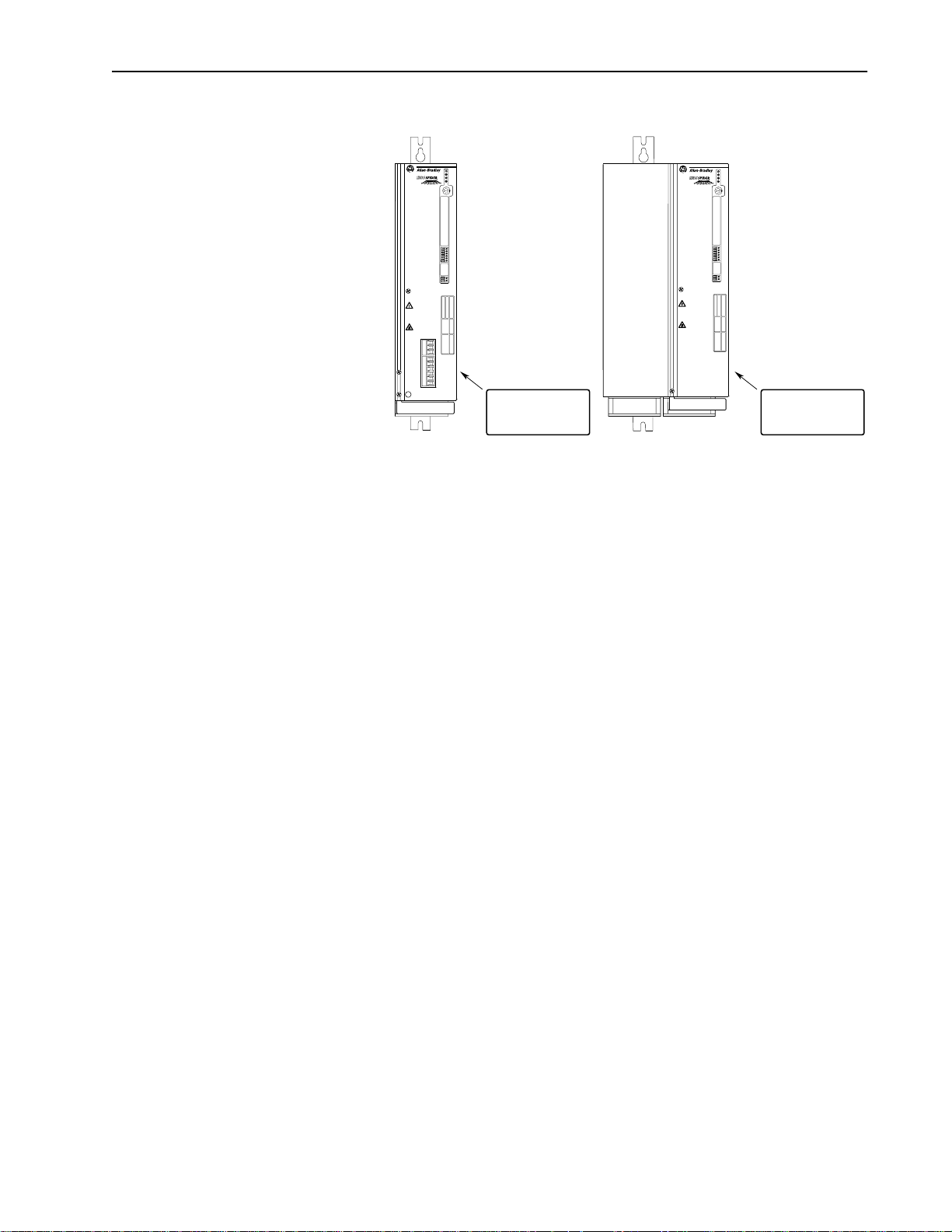
Nameplate Located on
Side Panel
9.9A through 36A Drives
PWR
RUN
STOP
FAULT
TB1
TB2
TB3
TB4
TB5
TB6
TB7
DEVICE IS LIVE UP TO
180SEC AFTER REMOVING
MAINS VOLTAGE.
GERÄT FÜHRT BIS
180SEK NACH DEM
AUSSCHALTEN SPANNUNG.
L'APPAREIL RESTE SOUS
TENSION JUSQU'A 180 S
APRES LA MISE HORS SERVICE.
Nameplate Located on
33A and 60A Drives
Side Panel
Page 10

1–4 Information and Precautions
End of Chapter 1
Page 11
Chapter 2
General Installation for All Drives
Chapter 2 provides the information you need to properly mount and
wire the main power connections of 1336 SPIDER Drives. In
addition, installation instructions are provided for the communication
options (GM1, GM2, etc.). Detailed control and signal wiring for the
Stand-alone or PLC control version is presented in Chapter 3 or 4,
respectively. Since most start-up difficulties are the result of incorrect
wiring, every precaution must be taken to assure that the wiring is
done as instructed. All items must be read and understood before the
actual installation begins.
ATTENTION: Thefollowinginformationismerely a
guide for proper installation. The Allen-Bradley
!
Company cannot assume responsibility for the
complianceorthenoncompliancetoanycode,national,
localorotherwisefortheproperinstallationofthisdrive
or associated equipment. A hazard of personal injury
and/or equipment damage exists if codes are ignored
during installation.
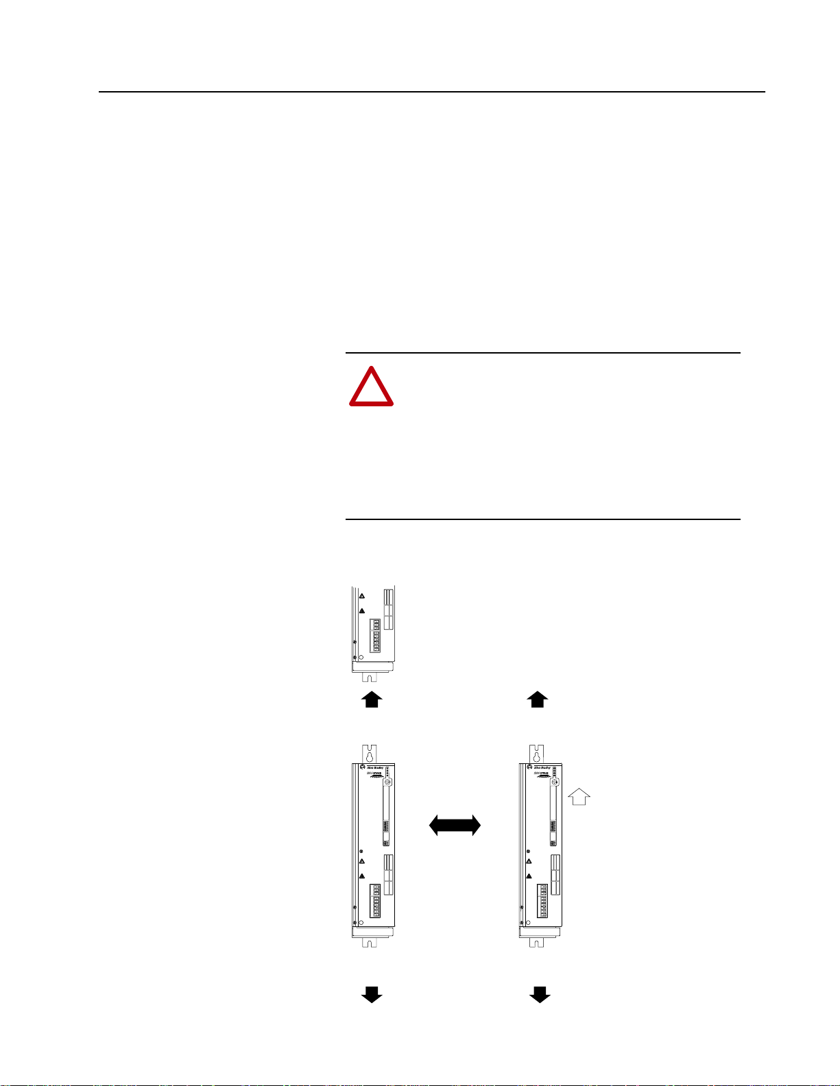
Mounting Minimum Mounting Requirements for Proper Heat Dissipation
(Dimensions shown are between drives or other devices)
DEVICE IS LIVE UP TO
180SEC AFTER REMOVING
MAINS VOLTAGE.
GERÄT FÜHRT BIS
180SEK NACH DEM
AUSSCHALTEN SPANNUNG.
L'APPAREIL RESTE SOUS
TENSION JUSQU'A 180 S
APRES LA MISE HORS SERVICE.
PE
101.6 mm
(4.0 in.)
PWR
RUN
STOP
FAULT
TB1
TB2
TB3
TB4
TB5
TB6
TB7
DEVICE IS LIVE UP TO
180SEC AFTER REMOVING
MAINS VOLTAGE.
GERÄT FÜHRT BIS
180SEK NACH DEM
AUSSCHALTEN SPANNUNG.
L'APPAREIL RESTE SOUS
TENSION JUSQU'A 180 S
APRES LA MISE HORS SERVICE.
PE
Normal Spacing
5.1 mm (0.2 in.)
15.2 mm (0.6 in.)
Required to
Remove Cover
101.6 mm
(4.0 in.)
PWR
RUN
STOP
FAULT
TB1
TB2
TB3
TB4
TB5
TB6
TB7
DEVICE IS LIVE UP TO
180SEC AFTER REMOVING
MAINS VOLTAGE.
GERÄT FÜHRT BIS
180SEK NACH DEM
AUSSCHALTEN SPANNUNG.
L'APPAREIL RESTE SOUS
TENSION JUSQU'A 180 S
APRES LA MISE HORS SERVICE.
PE
UP
101.6 mm
(4.0 in.)
101.6 mm
(4.0 in.)
Page 12
2–2 General Installation for All Drives
Installation Guidelines
GND
CAT. NO.
FREQUENCY
POWER RATING
PRIMARY VOLTAGE
SECONDARY VOLTAGE
INSULATION CLASS
NO. OF PHASES
VENDOR PART NO.
DEVICE IS LIVE UP TO
180SEC AFTER REMOVING
MAINS VOLTAGE.
GERÄT FÜHRT BIS
180SEK NACH DEM
AUSSCHALTEN SPANNUNG.
L'APPAREIL RESTE SOUS
TENSION JUSQU'A 180 S
APRES LA MISE HORS SERVICE.
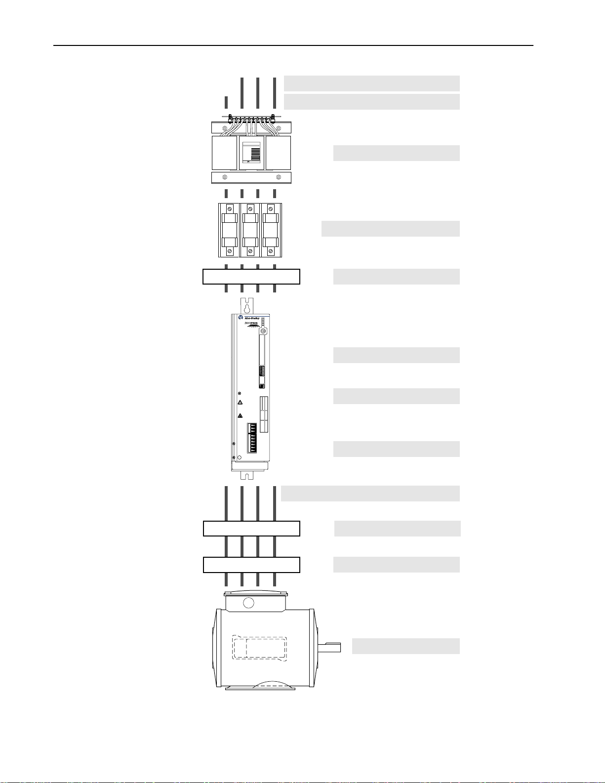
AC Supply Source
Harmonics/RFI/EMC
Page 2–3
Page 2–5 &
Appendix C
ALLEN-BRADLEY
Input Power Conditioning
Input Fusing & Circuit Breakers
Input Devices
PWR
RUN
STOP
FAULT
TB1
TB2
TB3
TB4
TB5
TB6
TB7
Electrical Interference
Grounding
Page 2–3
Page 2–4
Page 2–5
Page 2–5
Page 2–6
PE
Power Cabling
Control & Signal Cabling
Output Devices
Cable Termination
Page 2–9
Chapters 3 & 4
Page 2–12
Page 2–13
Motor
Page 13

General Installation for All Drives 2–3
AC Supply Source 1336 SPIDER drives are suitable for use on a circuit capable of
delivering up to a maximum of 200,000 rms symmetrical amperes,
600 volts.
ATTENTION: To guard against personal injury and/or
equipmentdamage causedby improperfusing, useonly the
!
recommended line fuses specified in Table 2.A.
Unbalanced Distribution Systems
This drive is designed to operate on earthed-neutral, three-phase
supply systems whose line voltages are symmetrical. 240V ACdrives
may be operated with one phase referenced to ground.
Ungrounded Distribution Systems
1336 SPIDER drives are not designed to operate in ungrounded
systems.
Input Power Conditioning In general, the 1336 SPIDER is suitable for direct connection to an
AC line of the correct voltage. Certain conditions can exist, however,
that prompt consideration of a line reactor or isolation transformer
ahead of the drive.
The basic rules to aid in determining whether a line reactor or
isolation transformer should be considered are as follows:
1. If the AC source experiences frequent power outages or
significant voltage transients, users should calculate the source
transformer VA. If thesource transformer VA exceeds the VAmax
(1MVA) and the drive is installed close to the source, it is an
indication that there may be enough energy behind these voltage
transients to cause nuisance input fuse blowing, overvoltage
faults or drive power structure damage. In these cases, a line
reactor or isolation transformer should be considered.
2. If the AC source does not have a neutral or one phase referenced
to ground (see Unbalanced Distribution Systems), an isolation
transformer with the neutral of the secondary grounded is required. If
the line-to-ground voltages on any phase can exceed 125% of the
nominal line-to-line voltage, an isolation transformer with the neutral
of the secondary grounded, is
3. If the AC line supplying the drive has power factor correction
capacitors that are switched in and out, an isolation transformer
or 5% line reactor is recommended between the drive and
capacitors. If the capacitors are permanently connected and not
switched, the general rules above apply.
highly recommended.
Page 14
2–4 General Installation for All Drives
Input Fuses The 1336 SPIDER should be installed with input fuses. However,
local/national electrical codes may determine additional requirements
for these installations.
Installations per U.S. NEC/UL/CSA
In general, the specified fuses are suitable for branch short circuit
protection and provide excellent short circuit protection for the drive.
The fuses offer a high interrupting capacity and are fast acting. Refer
to the North American selections in Table 2.A.
IEC Installations
For those installations that are not required to meet the U.S. NEC/
UL/CSA, the specified fuses are suitable for branch short circuit
protection and provide excellent short circuit protection for the drive.
The fuses offer a high interrupting capacity and are fast acting. Refer
to the selections in Tables 2.A and 2.B.
ATTENTION: The 1336 SPIDER does not provide input
powershort circuit protection.Specifications forthe recom-
!
mendedfusetoprovidedriveinputpowerprotectionagainst
short circuits is provided.
Table 2.A
Maximum Recommended AC InputLine Fuse Ratings (fuses are user supplied)
European
Installations
The recommended fuse is
Class gG, general
industrial applications.
NorthAmerican
Installations
The recommended fuse is
UL Class CC, T
or J.
Drive Catalog
Number
1336Z- _ A022 3.0 1.8 30A
1336Z- _ A036 5.0 3.0 30A
1336Z- _ A060 8.3 5.0 50A
1336Z- _ B010 2.7 1.6 20A
1336Z- _ B017 4.6 2.7 20A
1336Z- _ B033 9.1 5.5 40A
Drive Output
kVA Rating
Drive Output
kW Rating
Table 2.B
Recommended Fuses for Shared DC Bus Applications
(Fuses must be mounted between the drive and the shared DC bus)
AC Line
Rating Description Fuse Type
240V AC with Earthed Transformer
Star Point
with B Phase Grounded AJT (Gould or equivalent),
480V AC with Earthed Transformer
Star Point
LP-CC (Bussmann or equivalent),
300V DC rating
AJT (Gould or equivalent),
500V DC rating
500V DC rating
AJT (Gould or equivalent),
500V DC rating
Maximum
Fuse Rating
Maximum
Fuse Rating
See Table
2.A
Page 15

General Installation for All Drives 2–5
Input Devices Starting and Stopping the Motor
ATTENTION: The drive start/stop control circuitry includes solid-statecomponents. If hazards due to accidental
!
contact with moving machinery or unintentional flow of
liquid, gas or solids exist, an additional hardwired stop circuit may be required to remove ACline power to thedrive.
WhenAC power isremoved, there will be a lossof inherent
regenerativebrakingeffect &the motor will coast toa stop.
An auxiliary braking method may be required.
Repeated Application/Removal of Input Power
ATTENTION: The drive is intended to be controlled by
control input signals that will start and stop the motor. A
!
device that routinely disconnects then reapplies line power
to the drive for the purpose of starting and stopping the
motor is not recommended.
Electrical Interference - EMI/RFI Immunity
The immunity of 1336 SPIDER drives to externally generated
interference is good. Usually, no special precautions are required
beyond the installation practices provided in this publication.
Since coils can generate severe electrical transients, it is
recommended that the coils of DC energized contactors associated
with drives be suppressed with a diode or similar device. AC supplied
coils should utilize an R-C suppressor.
Emission
Careful attention must be given to the arrangement of power and
ground connections to the drive to avoid interference with nearby
sensitive equipment. The cable to the motor carries switched voltages
and should be routed well away from sensitive equipment.
The ground conductor of the motor cable must be connected to the
drive ground (PE) terminal directly. Connecting this ground
conductor to a cabinet ground point or ground bus bar may cause high
frequency current to circulate in the ground system of the enclosure.
The motor end of this ground conductor must be solidly connected to
the motor case ground.
Shielded cable must be used to guard against radiated emissions from
the motor cable. The shield must be connected to the drive ground
(PE) terminal and the motor ground as outlined above. Armored cable
can be used if radiation is not a concern.
Page 16

2–6 General Installation for All Drives
The drive has a smallcommon mode choke in the power output (U, V
& W). On installations that do not use shielded cable, additional
common mode chokes can help reduce common mode noise at the
drive output. Common mode chokes can also be used on analog or
communication cables. Refer to page 2–13 for further information.
An RFI filter can be used and in most situations provides an effective
reduction of RFI emissions that may be conducted into the main
supply lines.
If the installation combines a drive with sensitive devices or circuits,
it is recommended that the lowest possible drive PWM carrier
frequency be programmed.
RFI Filtering 1336 SPIDER drives can be ordered with an integral RFI filter, which
controls radio-frequency conducted emissions into the main supply
lines and ground wiring.
If the cabling and installation recommendation precautions described
in this manual are adhered to, it is unlikely that interference problems
will occur when the drive is used with conventional industrial
electronic circuits and systems. However, a filter may be required if
there is a likelihood of sensitive devices or circuits being installed on
the same AC supply.
Where it is essential that very lowemission levelsmust be achievedor
if conformity with standards is required the optional RFI filter must
be used. Refer to Appendix C for installation and grounding information.
CE Conformity Refer to Appendix C.
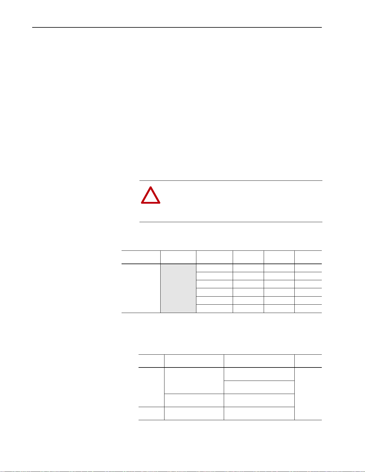
Grounding Refer to the grounding diagram on page 2–8. The drive must be
connected to system ground at the power ground (PE) terminal.
Ground impedance must conform to the requirements of national and
local industrial safety regulations (NEC, VDE 0160, BSI, etc.) and
should be inspected and tested at appropriate and regular intervals.
In any cabinet, a single, low-impedance ground point or ground bus
bar should be used. All circuits should be grounded independently
and directly. The AC supply ground conductor should also be
connected directly to this ground point or bus bar.
Sensitive Circuits
It is essential to define the paths through which the high frequency
ground currents flow. This will assure that sensitive circuits do not
share a path with such current. Control and signal conductors should
not be run near or parallel to power conductors.
Page 17

General Installation for All Drives 2–7
Motor Cable
The ground conductor of the motor cable (drive end) must be
connected directly to the drive ground (PE) terminal (see General
Grounding on page 2–8), not to the enclosure bus bar. Grounding
directly to the drive (and filter, if installed) can provide a direct route
for high frequency current returning from the motor frame and ground
conductor. At the motor end, the ground conductor should also be
connected to the motor case ground.
If shielded or armored cables are used, the shield/armor should also
be grounded at both ends as described above.
Discrete Control and Signal Wiring
The control and signal wiring must be grounded at the drive (see
General Grounding on page 2–8). If shielded control and signal wires
are used, the shield must also be grounded at the drive end only.
If the control and signal wires are short, and contained within a
cabinet which hasno sensitive circuits, the use of shielded control and
signal wiring may not be necessary, but is always recommended.
Safety Ground - PE (Potential Earth)
This is the safety ground required by code. This point must be
connected to adjacent building steel (girder, joist) or a floor ground
rod, provided grounding points comply with national or local electric
code regulations. The line input PE wire must be connected to the
bottom PE terminal (see General Grounding on page 2–8). If a
cabinet ground bus is used, refer to Grounding on page 2–6.
RFI Filter
Important: Using the integral RFI filter may result in relatively high
ground leakage currents. Surge suppression devices are
incorporated in the drive. The filter must be solidly
grounded. Grounding must not rely on flexiblecables and
should not include any form of plug or socket that would
permit inadvertent disconnection. The integrity of this
connection should be periodically checked.
Page 18
2–8 General Installation for All Drives
General Grounding
Conduit/4-Wire Cable
to Motor & Signal PE Ground
Nearest
Building Structure Steel
(for further grounding info, see "
PWR
RUN
STOP
FAULT
PE
DEVICE IS LIVE UP TO
180SEC AFTER REMOVING
MAINS VOLTAGE.
GERÄT FÜHRT BIS
180SEK NACH DEM
AUSSCHALTEN SPANNUNG.
L'APPAREIL RESTE SOUS
TENSION JUSQU'A 180 S
APRES LA MISE HORS SERVICE.
TB1
TB2
TB3
TB4
TB5
TB6
TB7
L1 (R)
L2 (S)
L3 (T)
Do Not Use
PE
RIO/DH+
Common
or Analog
Mode Core*
To Computer/Position Controller
Control and Signal Wiring" in Chapter 3 or 4
Single-Point Grounding/Panel Layout
L1 (R)
U (T1)
V (T2)
W (T3)
PE/Gnd.
Common
Mode
Core*
Shield*
Shield
Motor
Terminator*
)
Motor Frame
PE
Ground per
Local Codes
* Options that can be
installed as needed.
Nearest
Building Structure Steel
L2 (S)
L3 (T)
Zero Volt Potential Bus
(Isolated from Panel)
PE Ground Bus
(Grounded to Panel)
For Programmable Controller
grounding recommendations,
refer to publication 1770-4.1
1336 SPIDER 1336 SPIDER
PWR
RUN
STOP
FAULT
TB1
TB2
TB3
TB4
TB5
TB6
TB7
DEVICE IS LIVE UP TO
180SEC AFTER REMOVING
MAINS VOLTAGE.
GERÄT FÜHRT BIS
180SEK NACH DEM
AUSSCHALTEN SPANNUNG.
L'APPAREIL RESTE SOUS
TENSION JUSQU'A 180 S
APRES LA MISE HORS SERVICE.
PE
PE PE
PWR
RUN
STOP
FAULT
TB1
TB2
TB3
TB4
TB5
TB6
TB7
DEVICE IS LIVE UP TO
180SEC AFTER REMOVING
MAINS VOLTAGE.
GERÄT FÜHRT BIS
180SEK NACH DEM
AUSSCHALTEN SPANNUNG.
L'APPAREIL RESTE SOUS
TENSION JUSQU'A 180 S
APRES LA MISE HORS SERVICE.
PE
To Nearest Building
Structure Steel
Nearest Building
Structure Steel
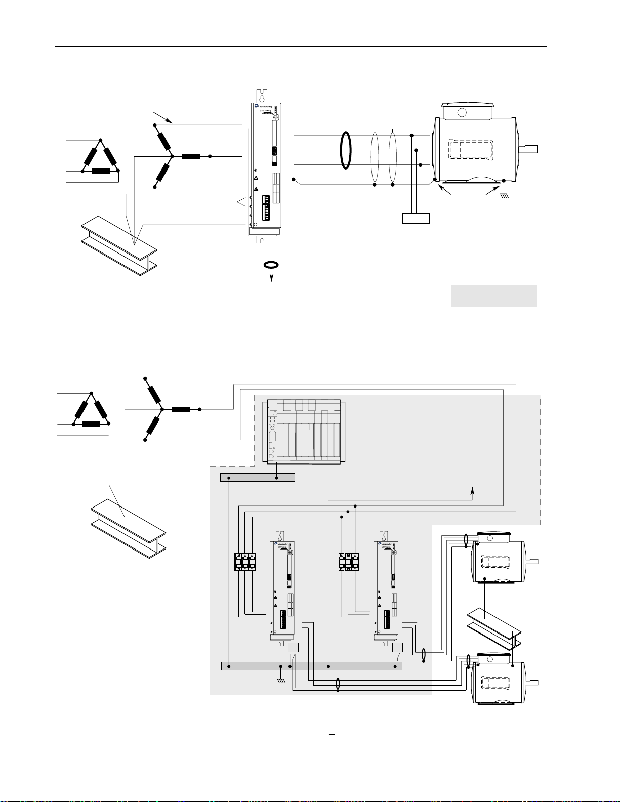
Important:Grounding requirementswillvarywith the drivesbeingused. Other driveswithTrueEarth (TE)terminalsmusthave azeropotentialbus, separate frompotential
earth(PE) ground bus. Notethat busescanbe tied together atonepoint in the control cabinetorbrought back separately tothebuilding ground grid (tied within3meters
(10 feet)).
Page 19
General Installation for All Drives 2–9
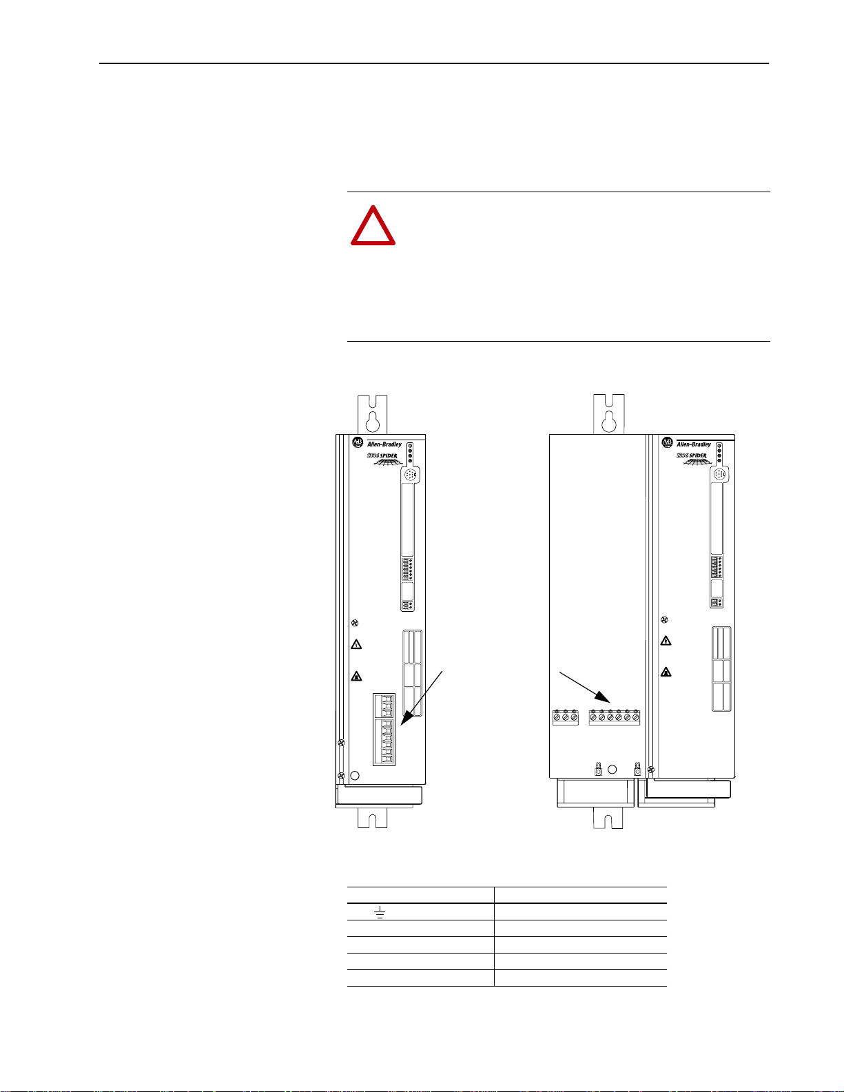
Power Cabling Input and output power connections are performed through the power
terminal blocks (see Figure 2.1 for location).
Important: For maintenance and setup procedures, the drive may be
operated without a motor connected.
ATTENTION: The National Codes and standards (NEC,
VDE,BSI etc.) andlocalcodes outlineprovisionsfor safely
!
installing electrical equipment. Installation must comply
with specifications regarding wire types, conductor sizes,
branch circuit protection anddisconnect devices.Failure to
do so may result in personal injury and/or equipment damage.
Figure 2.1
Power Terminal Block Locations
DEVICE IS LIVE UP TO
180SEC AFTER REMOVING
MAINS VOLTA GE.
GERÄT FÜHRT BIS
180SEK NACH DEM
AUSSCHALTEN SPANNUNG.
L'APPAREIL RESTE SOUS
TENSION JUSQU'A 180 S
APRES LA MISE HORS SERVICE.
45 (–)
47 (+)
PE
PWR
RUN
STOP
FAULT
TB1
TB2
TB3
TB4
TB5
TB6
TB7
Power Terminal Blocks
L1
L2
L3
48
U
V
W
Cover Removed to
Show Terminal
Blocks
L1 L2 L3 45
M4
(–)47(+)
48 U V W
PE
M4
DEVICE IS LIVE UP TO
180SEC AFTER REMOVING
MAINS VOLTA GE.
GERÄT FÜHRT BIS
180SEK NACH DEM
AUSSCHALTEN SPANNUNG.
L'APPAREIL RESTE SOUS
TENSION JUSQU'A 180 S
APRES LA MISE HORS SERVICE.
PWR
RUN
STOP
FAULT
TB1
TB2
TB3
TB4
TB5
TB6
TB7
Table 2.C
Power Terminal Block Signals
Terminal Description
PE Potential Earth Ground
L1 (R), L2 (S), L3 (T) AC Line Input Terminals
(+) 47 & (–) 45 DC Bus Terminals
(+) 47 & 48 Braking Resistor
U (T1), V (T2), W (T3) Motor Connection
Page 20

2–10 General Installation for All Drives
Table 2.D
Power Terminal Block Specifications
Drive Catalog
Number
1336Z-_ A022
1336Z-_ A036
1336Z-_ B010
1336Z-_ B017
1336Z-_ A060
1336Z-_ B033
1
Motor Cables
A variety of cable types are acceptable for drive installations. For
many installations, unshielded cable is adequate, provided it can be
separated from sensitive circuits. As an approximate guide, allow a
spacing of 0.3 meters (1 foot) for every 10 meters (32.8 feet) of
length. In all cases, long parallel runs mustbe avoided. Usecable with
the appropriate insulation class.
Max./Min. Wire Size
mm2 (AWG)
0.2/4 (24/10) M3 0.5-0.6 (4.4-5.3) 7 (0.28)
0.5/10 (20/6) M4 1.2-1.5 (10.6-13.3) 10 (0.39)
Wire sizes given are maximum/minimum sizes that terminal block will accept - these are not
recommendations. Use Copper wire only. Wire gauge requirements and recommendations are based
on 75 degree C. Do not reduce wire gauge when using higher temperature wire.
1
Screw
Size
Torque Range
N-m (lb.-in.)
Remove Insulation
mm (in.)
The cable should be 4-conductor with the ground lead being
connected directly to the drive ground terminal (PE) and the motor
frame ground terminal.
Shielded Cable
Shielded cable is recommended if sensitive circuits or devices are
connected or mounted to the machinery driven by the motor. The
shield must be connected to both the drive ground (drive end) and
motor frame ground (motor end). The connection must be made at
both ends to minimize interference.
If cable trays or large conduits are to be used to distribute the motor
leads for multiple drives, shielded cable is recommended to reduce or
capture the noise from the motor leads and minimize “cross coupling”
of noise between the leads of different drives. The shield should be
connected to the ground connections at both the motor and drive end.
Armored cable also provides effective shielding. Ideally it should be
grounded only at the drive (PE) and motor frame. Some armored
cable has a PVC coating over the armor to prevent incidental contact
with grounded structure. If, due to the type of connector, the armor is
grounded at the cabinet entrance, shielded cable should be used
within the cabinet if power leads will be run close to control signals.
In some hazardous environments it is not permissible to ground both
ends of the cable armor because of the possibility of high current
circulating at the input frequency if the ground loop is cut by a strong
magnetic field. This only applies in the proximity of powerful
electrical machines. In such cases, consult factory for specific
guidelines.
Page 21

General Installation for All Drives 2–11
Conduit
If metal conduit is preferred for cable distribution, the following
guidelines should be followed.
• Drives are normally mounted in cabinets and ground connections
are made at a common ground point in the cabinet. Normal
installation of conduit provides grounded connections to both the
motor frame ground (junction box) and drive cabinet ground.
These ground connections help minimize interference. This is a
noise reduction recommendation only, and does not affect the
requirements for safety grounding (refer to pages 2–6 and 2–7).
• No more than three sets of motor leads can be routed through a
single conduit. This will minimize “cross talk” that could reduce
the effectiveness of the noise reduction methods described. If
more than threedrive/motor connections per conduit are required,
shielded cable as described above must be used. If practical, each
conduit should contain only one set of motor leads.
ATTENTION: Toavoidapossible shockhazardcaused by
induced voltages, unused wires in the conduit must be
!
grounded at both ends. For the same reason, if a drive sharing a conduit is being serviced or installed, all drives using
this conduit should be disabled. This will eliminate the possible shock hazard from “cross coupled” drive motor leads.
Motor Lead Lengths
Installations with long cables to the motor may require the addition of
output reactors or cable terminators to limit voltage reflections at the
motor. Excessive cable charging current can also reduce the amount
of current available to produce rated motor torque. Refer to Table 2.E
for the maximum cable length allowed for various installation
techniques. Shaded distances are restricted by cable capacitance
charging current. The figure on the next page illustrates how total
cable length iscalculated. Failure to followthese guidelines can result
in poor motor performance and nuisance drive overcurrent or
overload tripping. For installations that exceed the recommended
maximum lengths listed, contact the factory.
Please note that the cable lengths shown are guidelines. Your
application may be restricted to a shorter cable length due to wire
type, wire placement, line reactor and type of motor.
Dynamic Brake Resistor Wiring
All brake resistor wiring must be twisted wire run in conduit separate
from control wiring. Maximum cable length is 2.5 meters (8.2 feet).
Size wire according to the “Brake Current” provided on page A–3.
Brake resistor dimensions and specifications can be found in
Appendix B.
Page 22
2–12 General Installation for All Drives
How to Measure Motor Cable Lengths Limited by Capacitance
PWR
RUN
STOP
FAULT
TB1
TB2
TB3
TB4
TB5
TB6
TB7
DEVICE IS LIVE UP TO
180SEC AFTER REMOVING
MAINS VOLTAGE.
GERÄT FÜHRT BIS
180SEK NACH DEM
AUSSCHALTEN SPANNUNG.
L'APPAREIL RESTE SOUS
TENSION JUSQU'A 180 S
APRES LA MISE HORS SERVICE.
PE
PWR
RUN
STOP
FAULT
TB1
TB2
TB3
TB4
TB5
TB6
TB7
DEVICE IS LIVE UP TO
180SEC AFTER REMOVING
MAINS VOLTAGE.
GERÄT FÜHRT BIS
180SEK NACH DEM
AUSSCHALTEN SPANNUNG.
L'APPAREIL RESTE SOUS
TENSION JUSQU'A 180 S
APRES LA MISE HORS SERVICE.
PE
PWR
RUN
STOP
FAULT
TB1
TB2
TB3
TB4
TB5
TB6
TB7
DEVICE IS LIVE UP TO
180SEC AFTER REMOVING
MAINS VOLTAGE.
GERÄT FÜHRT BIS
180SEK NACH DEM
AUSSCHALTEN SPANNUNG.
L'APPAREIL RESTE SOUS
TENSION JUSQU'A 180 S
APRES LA MISE HORS SERVICE.
PE
PWR
RUN
STOP
FAULT
TB1
TB2
TB3
TB4
TB5
TB6
TB7
DEVICE IS LIVE UP TO
180SEC AFTER REMOVING
MAINS VOLTAGE.
GERÄT FÜHRT BIS
180SEK NACH DEM
AUSSCHALTEN SPANNUNG.
L'APPAREIL RESTE SOUS
TENSION JUSQU'A 180 S
APRES LA MISE HORS SERVICE.
PE
15 (50)
90 (295)
90 (295)
165 (540)
180 (590)
150 (490)
15 (50) 15 (50)
All examples represent motor cable length of 180 meters (590 feet).
Table 2.E
Maximum Motor Cable Length Restrictions in meters (feet) - 380V-480V Drives
No External Devices 1321-3R55-A Reactor at Drive 1321-3R25-A Reactor at Drive
Motor Insulation Class
not less than . . .
Motor Insulation Class
not less than . . .
Motor Insulation Class
not less than . . .
Drive Catalog
Number
Peak
Current
Rating
1
Cable
Diameter
mm2 (AWG)
220-240V AC 800V 1000V 1200V 800V 1000V 1200V
1336Z- _ A022 21.6A 2.5 (12) 120 (394) 120 (394) 120 (394) 180 (590) 180 (590) 180 (590)
1336Z- _ A036 36.0A 2.5 (12) 180 (590) 180 (590) 180 (590) 180 (590) 180 (590) 180 (590)
1336Z- _ A060 60.0A 6.0 (8) 180 (590) 180 (590) 180 (590) 180 (590) 180 (590) 180 (590)
380-400V AC 1000V 1200V 1400V 1000V 1200V 1400V 1000V 1200V 1400V
1336Z- _ B010 9.9A 2.5 (12) 15 (50) 105 (344) 105 (344) 30 (98) 180 (590) 180 (590) 60 (197)
1336Z- _ B017 16.5A 2.5 (12) 15 (50) 115 (377) 115 (377) 30 (98) 180 (590) 180 (590) 60 (197)
1336Z- _ B033 33.0A 6.0 (8) 15 (50) 155 (509) 180 (590) 30 (98) 180 (590) 180 (590) 60 (197)
460-480V AC 1200V 1400V 1600V 1200V 1400V 1600V 1200V 1400V 1600V
1336Z- _ B010 9.9A 2.5 (12) 15 (50) 105 (344) 105 (344) 30 (98) 180 (590) 180 (590) 60 (197)
1336Z- _ B017 16.5A 2.5 (12) 15 (50) 115 (377) 115 (377) 30 (98) 180 (590) 180 (590) 60 (197)
1336Z- _ B033 33.0A 6.0 (8) 15 (50) 120 (394) 180 (590) 30 (98) 180 (590) 180 (590) 60 (197)
1
This current is only possible with synchronous motors and for spinning applications. For actual motor current rating, refer to Appendix A.
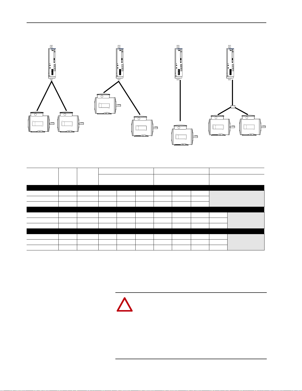
Output Devices Drive Output Disconnection
ATTENTION: Toguard againstdrive damage, always disablethedrivebefore disconnecting themotorfrom the drive
!
output terminals. Any disconnecting means wired to the
drive output terminals U, V and W must be capable of disabling the driveif opened duringdrive operation.If opened
(motor disconnected) during drive operation, the drive will
continue to produce output voltage between U, V, & W
(drive damage could occur). An auxiliary contact must be
used to simultaneously disable the drive.
Page 23

General Installation for All Drives 2–13
Common Mode Cores
The 1336 SPIDER includes an integral output common mode core.
This will help reduce the common mode noise at the drive output and
guard against interference with other electrical equipment (programmable controllers, sensors, analog circuits, etc.). In addition, reducing
the PWM carrier frequency will reduce the effects and lower the risk
of common mode noise interference. Refer to the table below for
additional information.
Table 2.F
1336 SPIDER Common Mode Chokes
Catalog Number Used with . . . Description
1321-M001 Communications Cables, Analog
Signal Cables, etc.
Cable Termination Optional Cable Terminator
Voltage doubling at motor terminals, known as reflected wave phenomenon, standing wave or transmission line effect, can occur when
using drives with long motor cables.
Open Style - Signal Level
Inverter duty motors with phase-to-phase insulation ratings of 1200
volts or higher should be used to minimize effects of reflected wave
on motor insulation life.
Applications with non-inverter duty motors or any motor with exceptionally long leads may require an output filter or cable terminator. A
filter or terminator will help limit reflection to the motor, to levels
which are less than the motor insulation rating.
Table 2.D lists the maximum recommended cable length for unterminated cables, since the voltage doubling phenomenon occurs at different lengths for different drive ratings. If your installation requires
longer motor cable lengths, a reactor or cable terminator is recommended.
Optional Input/Output Reactor Specifications
Bulletin 1321 Reactors listed in the 1336 PLUS-3.0 Price Sheet can
be used for drive input and output. These reactors are specifically
constructed to accommodate IGBT inverter applications with switching frequencies up to 20 kHz. They have a UL approved dielectric
strength of 4000 volts, opposed to a normal rating of 2500 volts. The
first two and last two turns of each coil are triple insulated to guard
against insulation breakdown resulting from high dv/dt. When using
motor line reactors, it is recommended that the drive PWM frequency
be set to its lowest value to minimize losses in the reactors.
Important: By usingan outputreactor theeffectivemotor voltage will
be lower because of the voltage drop across the reactor this may also mean a reduction of motor torque.
Page 24
2–14 General Installation for All Drives
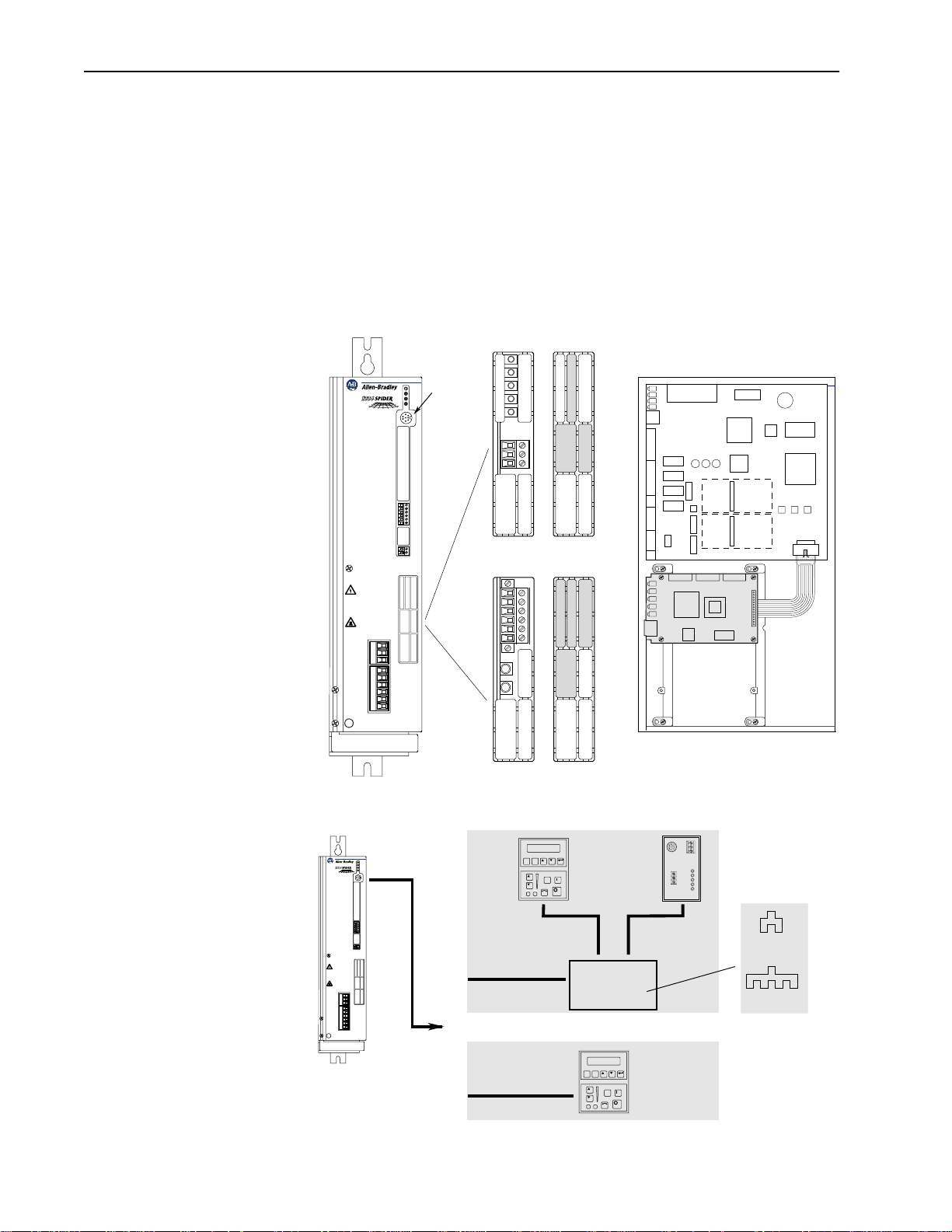
Adapter Definitions and
Communication Option
Installation
Serial communication devices such as the Human Interface Module
that are connected to the drive are identified by SCANport as
Adapters. Depending on the drive and options ordered, different
adapters are available. The communication options available for the
1336 SPIDER can be mounted as shown in Figure 2.2. Access to the
communication ports and LEDs is gained by removing the knockouts
shown. Figure 2.3 shows the maximum distance allowed between
external devices.
Figure 2.2
Adapter Locations
Remote I/O
Adapter 2
DEVICE IS LIVE UP TO
180SEC AFTER REMOVING
MAINS VOLTAGE.
GERÄT FÜHRT BIS
180SEK NACH DEM
AUSSCHALTEN SPANNUNG.
L'APPAREIL RESTE SOUS
TENSION JUSQU'A 180 S
APRES LA MISE HORS SERVICE.
45 (–)
47 (+)
PE
PWR
RUN
STOP
FAULT
TB1
TB2
TB3
TB4
TB5
TB6
TB7
(Remove Shaded Areas)(Installed)
DeviceNet
Adapter 1
L1
L2
L3
48
U
V
W
J1
J3
TB1
Slot A
Slot B
(Communication Board Installed)
J11
J8
J13
J2
(Remove Shaded Areas)
(Installed)
Figure 2.3
Remote Device Distances
RIO
PWR
RUN
STOP
FAULT
TB1
TB2
TB3
TB4
TB5
TB6
TB7
DEVICE IS LIVE UP TO
180SEC AFTER REMOVING
MAINS VOLTAGE.
GERÄT FÜHRT BIS
180SEK NACH DEM
AUSSCHALTEN SPANNUNG.
L'APPAREIL RESTE SOUS
TENSION JUSQU'A 180 S
APRES LA MISE HORS SERVICE.
L1
L2
L3
45 (–)
47 (+)
48
U
V
W
PE
Total cable distance between
each device and drive must
Length = X Meters
ESC SEL
JOG
Cable Length in
Meters = 10 – X
Maximum Cable
Length = 10 Meters
HIM or Other
Remote Device
Port Expansion
Option
(1203-SG2)
or
ESC SEL
JOG
be 10 meters (33 feet) or less.
1
Communications Port for remote HIM/communication options (Adapter 2) or Expansion Options (Adapters 2, 3, 4, 5) is located at TB1.
SCANport
Comm
Status
120/240V AC
Input
Communication Module
Cable Length in
Meters = 10 – X
HIM or Other
Remote Device
23
1203-SG2
2345
1203-SG4
Expansion Options
1
Page 25

Installation/Wiring for Stand-Alone Drives
Chapter 3 provides the information you need to perform the control
and signal wiring for Stand-alone 1336 SPIDER Drives. In addition,
installation information is provided for the Analog Option Boards.
Refer to Chapter 2 for general installation and wiring.
Control and Signal Wiring General Wiring Information
General requirements for analog and digital signal wire include:
stranded copper 0.750-0.283 mm
shield, 300V minimum insulation rating and a temperature rating
suitable for the application (not less than 60 degrees C.). Refer to
Table 3.A for terminal block specifications and Figure 3.1 for
locations.
Chapter 3
2
(18-22 AWG), twisted-pair, 100%
Table 3.A
Control and Signal Terminal Block Specifications
Drive Catalog
Number
All 0.14-1.5 (28-16) M2 0.22-0.25 (1.9-2.2) 9 (0.35)
1
Wire sizes given are maximum/minimum sizes that terminal block will accept - these are not
recommendations. Use Copper wire only. Wire gauge requirements and recommendations are based
on 75 degree C. Do not reduce wire gauge when using higher temperature wire.
Max./Min. Wire Size
mm2 (AWG)
1
Screw
Size
Torque Range
N-m (lb.-in.)
Remove Insulation
mm (in.)
Signal Connections
If the drive control connections are to be linked to an electronic
circuit or device, the common or 0V line should, if possible, be
grounded at the device (source) end only.
Important: The signal common (0V) of the drive is internally
connected to PE. User speed reference signals are
terminated to logiccommon at TB2, terminal 5. This puts
the negative (or common) side of these signals at earth
ground potential. Control schemes must be examined for
possible conflicts with this type of grounding scheme.
Cable Routing
If unshielded cable is used, signal circuits should not run parallel to
motor cables or unfiltered supply cables with a spacing less than 0.3
meters (1 foot). Cable tray metal dividers or separate conduit should
be used.
Important: When user installed control and signal wiring with an
insulationratingofless than 600Vis used,thiswiringmust
be routed inside the drive enclosure and separated from
any other wiring and/or uninsulated live parts.
Page 26
3–2 Installation/Wiring for Stand-Alone Drives
Figure 3.1
Control and Signal Terminal Blocks
PWR
RUN
STOP
FAULT
TB1
1
2
3
TB2
4
5
6
7
8
9
10
11
12
TB3
13
14
15
16
17
TB4
18
19
20
21
22
TB5
23
24
25
26
27
TB6
28
29
30
24VC
TB7
24V
TB1
TB2
TB3
TB4
TB5
TB6
TB7
PWR
RUN
STOP
FAULT
1
2
3
4
5
6
7
8
9
10
11
12
13
14
15
16
17
18
19
20
21
22
23
24
25
26
27
28
29
30
24VC
24V
Digital Inputs Digital inputs are connected at TB4-TB6.
Input Mode Select
A number of combinations are available by first programming
[Input Mode] to the desired control scheme (i.e. 2 wire, 3 wire or
Status). The remaining inputs can then be configured by
programming parameters 242-247 ([TB5 Term 22 Sel] - [TB6 Term
28 Sel]). Refer to the table on page 3–5 and the Digital I/O parameter
group in Chapter 7 for programming information.
Page 27
Input 1
Input 2
TB4
19
TB5
20
Installation/Wiring for Stand-Alone Drives 3–3
Figure 3.2
Digital I/O Default Settings
Input Mode (Start/Stop Functions Only)
2
Status
(Factory Default)
Status Run Forward Start
Stop/Fault Reset
2-Wire Control
Single-Source Control
3
Stop/Fault Reset3Stop/Fault Reset
3-Wire Control
Single-Source Reversing
3
Common
Input 3
Input 4
Input 5
Common
Input 6
Input 7
Input 8
Common
Input 9
24V Common
21
22
23
24
25
TB6
26
27
28
29
30
TB7
24V
Common
Rev/For4 (Programmable)
Status Only
Default Mode
shown at right
is not active
when
[Input Mode]
is set to "Status"
3
Enable
1
See
Speed Select
2
If this mode is selected, the status of all inputs can be read at the [Input Status] parameter.
However, only “Stop/Fault Reset” and “Enable” will have control function.
3
These inputs must be present (reprogram if necessary) before drive will start.
4
Bit 0 of [Direction Mask] must = 1 to allow TB5 direction change/bipolar operation.
Jog (Programmable)
Auxiliary3 (Programmable)
Common
1
Speed Select 3
Speed Select 21 (Programmable)
Speed Select 11 (Programmable)
Common
Enable
Table.
(Programmable)
3
(Not Programmable)
Factory
Default Inputs
ATTENTION: A hazard of personal injury from
automatic restart exists with 2-wire control. 2-wire
!
control uses maintained Run contacts that act as both
Run(closed)andStop (open) devices.OpeningtheStop
contact (terminal 20) will stop the drive.If this contact
is reclosed, any fault will be reset. If a valid Start
commandisstill present,thedrivewillrestart.Only use
2-wire control for applications outlined in NFPA79,
“Under Voltage Protection.”
If a 3-wire device (i.e. HIM) is also used, pressing the
HIM Stop key will also stop the drive. Releasing the
Stop key will clear any faults that are present, but the
drive will not restart without cycling the Start contact.
Page 28
3–4 Installation/Wiring for Stand-Alone Drives
Circuits must be capable of operating with high = true logic.
DC external circuits in the low state must generate a voltage of no
more than 8V DC. Leakage current must be less than 1.5 mA into a
2.5k ohm load.
DC external circuits in the high state must generate a voltage of +20
to +26 volts and source a current of approximately 10 mA for each
input. The stand-alone version is compatible with these
Allen-Bradley PLC modules:
• 1771-OB • 1771-OQ16 • 1771-OB16
• 1771-OBD • 1771-OYL
• 1771-OBN • 1771-OZL
• 1771-OQ • 1771-OBB
The 24 volt power supply is capable of supplying a total of 16 digital
inputs.
510 510
20k
Typical
0.22µf
510
1k
2019 21 22 23 24 25
TB4 TB5 TB6 TB7
Contacts shown are general, refer to Input Mode Select and information presented above.
26 27 28 29 30
24V Common
24V
Page 29

Installation/Wiring for Stand-Alone Drives 3–5
Available Functions for Inputs 3 through 8
A variety of combinations made up of the following inputs are a v ailable.
Input Description
“2 Acc/1 Acc”
“2 Dec/1 Dec”
“1st Accel”
“2nd Accel”
“1st Decel”
“2nd Decel”
“Aux Fault” Faultsthe drivevia externaldevices (i.e. motor thermoswitch,O.L. relays, etc.).Opening this
“Clear Fault” If drive has faulted, closing this input will clear the fault.
“Dig Pot Up”
“Dig Pot Dn”
“Forward” Closing these inputs (Forward or Reverse) commands the corresponding direction. If both
“Rev/For” Available only with three-wire control - Closing this input commands reverse direction and
“Jog” Closingthis inputstarts thedrive and causesit torun at programmedjog frequency.Opening
“Local Ctrl” Closing this input gives exclusive control of drive logic to the inputs at terminals 19-30. No
“Reverse” See “Forward” above.
“PI Enable” Enables the output of the process PI loop.
“PI Reset” Opening this input clamps the process PI integrator value at zero. Closing this input allows
“Run Reverse” Available Only with two-wire control - Closing this input issues both a start command and a
“Speed Sel 1”
“Speed Sel 2”
“Speed Sel 3”
“Stop Type” Closing thisinput selectsthe stopmode in [Stop Select 2] as the method ofstopping whena
“Sync” Normally wired to multiple drives – When the Sync input is low, the drive operates normally.
“Traverse” Settingthis inputlow disablesthe traverse function. When the input is high,the traversefunc-
Closing these inputs will command the corresponding accel or decel rate. If both inputs are
open or both are closed, the current rate is maintained.
Input 1st2
No Command 0 0
Accel/Decel 1 0 1
Accel/Decel 2 1 0
Allows selection of the accel or decel time used by the drive. 1=2nd, 0=1st
contact will fault(F02 -Aux Fault) thedrive andshut theoutput off,ignoring theprogrammed
stop mode.
These inputs increase (up) or decrease (down) the drive commanded frequency when MOP
(Motor Operated Potentiometer) is chosen as the frequency command source. The rate of
increase/decrease is programmable.
inputs are open or both are closed, the current direction is maintained.
opening this input commands forward direction.
this input stops the drive using the programmed stop mode.
other devices may issue logic commands (excluding Stop) to the drive.
the integrator to continue to operate.
reverse command to the drive. Opening the input issues a stop command to the drive.
These inputs choose the frequency command source for the drive. See following pages for
details.
stop command is issued. Opening this input selects the stop mode in [Stop Select 1] as the
method of stopping.
When the input ishigh, the speed of the drive willbe held constant and the speed command
willhave no effect.During thisperiod thespeed input ofthe drivewill normally be changedto
a different source and/or value. Allows synchronizedchange of frequency command tomultiple drives.
tion will be active. [Speed Control] must also be set to “P Jump” for the function to be active.
nd
Important: The [Input Mode] parameter can be changed at any time,
but the change will not affect drive operation until power
tothe drivehas beenremovedand busvoltagehas decayed
completely. When changing thisparameter,it is important
to note that the functions of the Start and Stop inputs will
change when power is reapplied to the drive.
The programming options allowyou to select an input combination to
meet the needs of a specific installation. The firmware will verify
programming, to assure selection of an appropriate combination.
Page 30

3–6 Installation/Wiring for Stand-Alone Drives
Speed Select/Frequency Reference
The drivespeed command can be obtained from a number of different
sources. The source is determined by drive programming and the
condition of the Speed Select Inputs on TB6 (or reference select bits
of command word if PLC controlled - see Appendix A).
The default source for a command reference (all speed select inputs
open) is the selection programmed in [Freq Select 1]. If any of the
speed select inputs are closed, the drive will use other parameters as
the speed command source. See Table 3.B and the examples that
follow.
Table 3.B
Speed Select Input State vs. Frequency Source
Speed Select 3 Speed Select 2 Speed Select 1 Frequency Source
Open Open Open [Freq Select 1]
Open Open Closed [Freq Select 2]
Accessed through [Freq Select 2] parameter [Preset Freq 1]
Open Closed Open [Preset Freq 2]
Open Closed Closed [Preset Freq 3]
Closed Open Open [Preset Freq 4]
Closed Open Closed [Preset Freq 5]
Closed Closed Open [Preset Freq 6]
Closed Closed Closed [Preset Freq 7]
Important: The final speed command may be affected by the type of
modulation selected with [Speed Control], parameter 77.
See [Speed Control] in Chapter 7 for further information.
Important: If a bi-polar input option (LA6 or LA7) is installed, the
signal is designated “AnalogInput 0.”Note thefollowing:
3 Wire Control – If [Input Mode] is set to “3 Wire”
and the bi-polar input is selected as the active
frequency reference [Freq Select 1 or 2], it is
assumed that direction control is desired via analog
polarity. If another source has control of direction, a
“Bipolar Direction” fault (F16) will occur. If
direction control via polarity is not required, bit 7 of
[Direction Mask] should be set to “0.” This causes
the input to be treated as a 0-10V frequency
reference only. Negative analog signals are treated
as zero and direction control must come from
another source.
2 Wire Control – If [Input Mode] is set to “2 Wire,”
it is assumed that direction control is provided via
the 2 wire inputs (Run Forward and Run Reverse).
Bit 7 of [Direction Mask] must be set to “0.” This
causes the input to be treated as a 0-10V frequency
reference only. Negative analog signals are treated
as zero. Failure to set the Mask will generate a
“Bipolar Direction” (F16) fault.
Page 31

Installation/Wiring for Stand-Alone Drives 3–7
Example 1
3 Wire Control - Application calls for a local Human Interface
Module (HIM) speed command or remote 4-20mA from a PLC. The
drive is programmed as follows:
• [Freq Select 1] = Adapter 1
• [Freq Select 2] = Analog Input 0
With Speed Select inputs 2 & 3 open and the selector switch set to
“Remote” (Speed Select 1 closed), the drive will follow [Freq Select
2] (Analog Input 0). With the switch set to “Local” (Speed Select 1
open) all speed select inputs are open and the drive will follow the
local HIM (Adapter 1) as selected with [Freq Select 1].
Speed Select 3 (Open)
Speed Select 2 (Open)
Speed Select 1
Remote
Local
26
27
28
Example 2
Application is to follow a local HIM unless a preset speed is selected.
The drive is programmed as follows:
• [Freq Select 1] = Adapter 1
• [Freq Select 2] = Preset Freq 1
• [Preset Freq 1] = 10 Hz.
• [Preset Freq 2] = 20 Hz.
• [Preset Freq 3] = 30 Hz.
Contact operation for the speed select switch is described in the table
below. If the user does not select an input as Speed Select 3, [Preset
Freq 4-7] would not be available.
Local
See Table
1
26
2
3
27
28
Speed Select 2
Speed Select 1
Switch
Position
Local Open Open [Freq Select 1] Adapter 1
1 Closed Open [Freq Select 2] Preset Freq 1
2 Open Closed [Preset Freq 2] 20 Hz.
3 Closed Closed [Preset Freq 3] 30 Hz.
Speed Select Input
Parameter Used for
Speed Ref.
Programmed
Setting1 (#28) 2 (#27)
Page 32

3–8 Installation/Wiring for Stand-Alone Drives
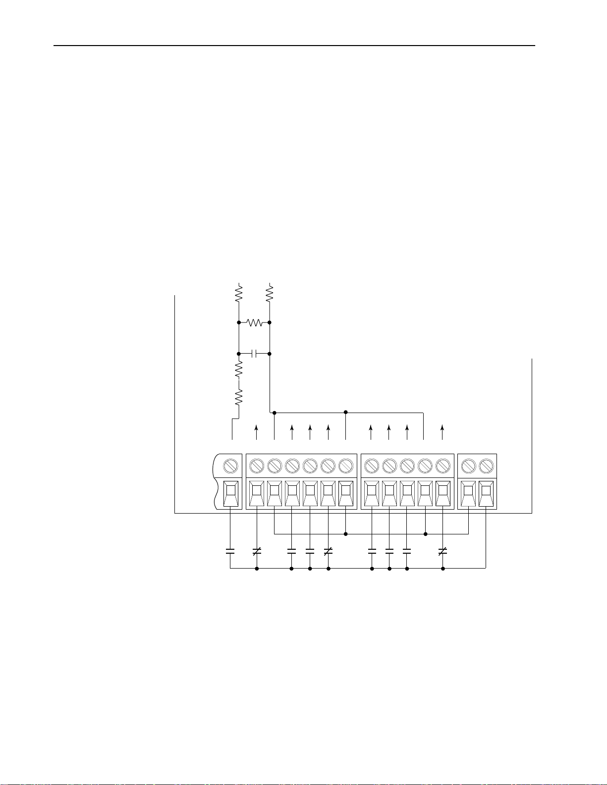
Pulse Input/Output Option Pulse Input
!
The pulse input signal must be an externally powered square-wave
pulse at a 5V TTL logic level. As measured at the terminal block,
circuits in the high state must generate a voltage between 3.6 and
5.5V DC at 8 mA. Circuits in the low state must generate a voltage
between 0.0 and 0.8V DC. Maximum input frequency is 250kHz.
Scale factor [Pulse/Enc Scale] must be set.
Pulse Output
Provides a TTL pulse train suitable for driving up to three
1336 SPIDER pulse inputs or a separate 125 ohm load at TTL levels
(4V at 32 mA source, 0.8V at 3.2 mA sink).
Important: An LA5 Analog Option must be installed to use the pulse
ATTENTION: If input voltages are maintained at levels
above ±15V DC, signals may be degraded and component
damage may result.
input/output options. See Figure 3.4 for terminal
designations.
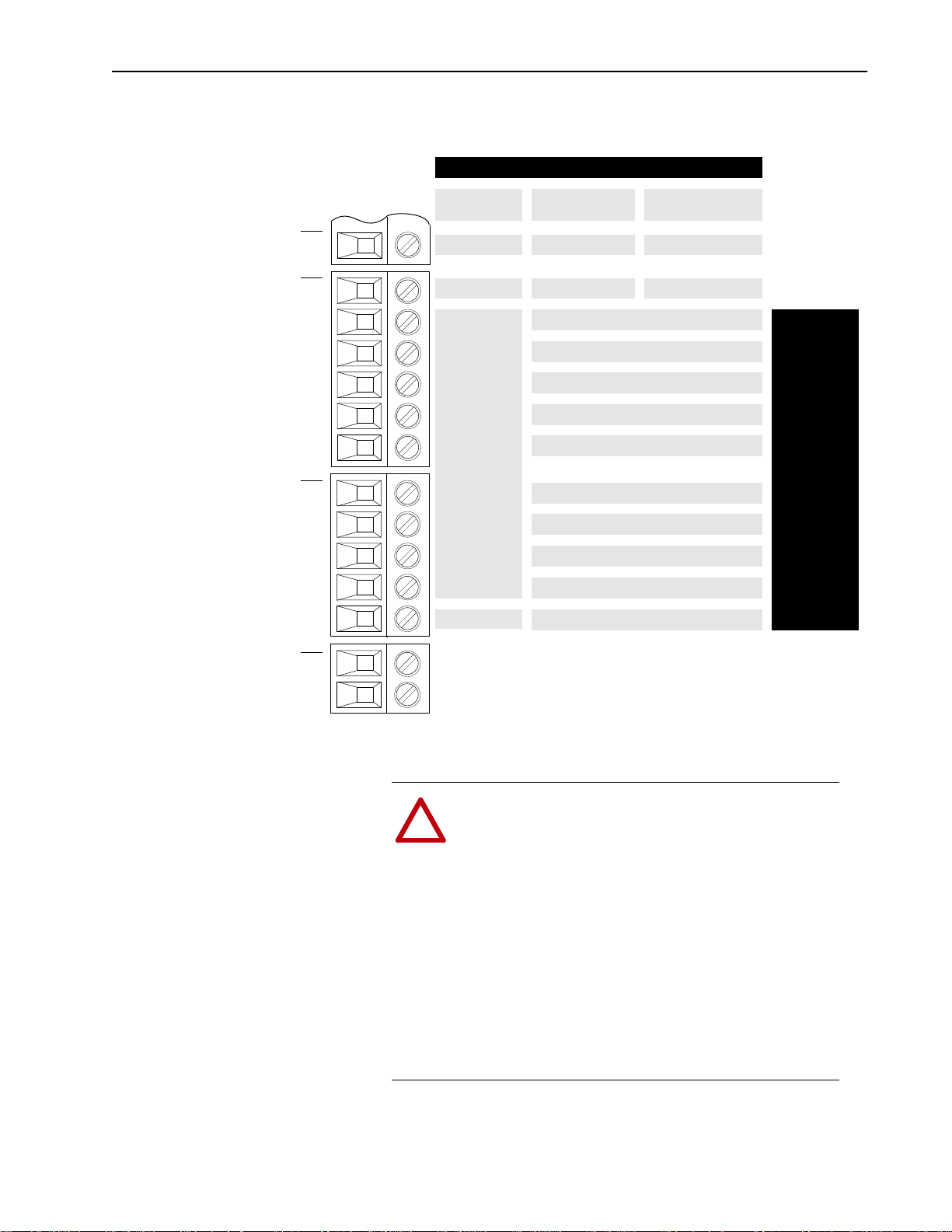
Digital Outputs The digital outputs are at terminals 10 through 18 of TB3-TB4.
Figure 3.3
Digital Outputs
TB3
Contacts Shown
in Unpowered State
(or powered state with
fault/alarm present)
Terminal
10, 11
11, 12
13, 14
14, 15
16, 17
17, 18
Signal
CR1 Programmable Contact
CR2 Programmable Contact
CR3 Programmable Contact
CR4 Programmable Contact
CR1
CR2
CR3
CR3
CR4
CR4
10
11
12
13
14
15
16
17
18
Resistive Rating = 115V AC/30V DC, 5.0A
Inductive Rating = 115V AC/30V DC, 2.0A
Output 1
Common
Output 2
Output 3
Common
Output 4
Output 5
TB4
Common
Output 6
Important: The power supply used for relay contact outputs requires a field installation
of transient voltage surge suppression with maximum clamping voltage of
2.5 kV on all control boards.
Page 33

Installation/Wiring for Stand-Alone Drives 3–9
Analog I/O The 1336 SPIDERanalog I/O configuration provides a standard set of
inputs and outputs with the capability to install up to 2 option boards,
thus replacing the standard I/O with a variety of options. All
connections are performed at TB2 and TB3. Installing an option
board in the slot A or B location will change the function of those
terminals on TB2-TB3 from standard. Only one option board can be
installed in each slot. Figure 3.4 shows the standard and optional I/O
configurations.
Figure 3.4
Analog I/O – TB2 and TB3
TB2 TB3
123 4567 8 9
Standard
Analog I/O
Pot.
Std.
Reference
1
+5V
Isolated
Input 0 (+)
LA2
10V or 20mA
Isolated
Input 0 (+)
LA6
±
10V, ±20mA
Isolated
Input 0 (+)
LA7
±
10V, ±20mA
1
If an Option Board is installed in Slot A, the +5V pot. reference will not be
available. If a 5V source is required, it must be user supplied.
Standard Analog Input 2
(Non-Isolated)
56
++––
0-10V
Jumper J11 Set to "0-10V"
Single-Ended
Input 0
Pot., 10V or 20mA
Isolated
Input 0 (–)
10V or 20mA
Isolated
Input 0 (–)
±
10V, ±20mA
Isolated
Input 0 (–)
±
10V, ±20mA
Single-Ended
Input 1
Pot., 10V or 20mA
or (select 1) or (select 1)
Isolated
Input 1 (+)
10V or 20mA
Thermistor
Isolated
Input (+)
Isolated
Input 1 (+)
10V or 20mA
Signal
Common
Isolated
Input 1 (–)
10V or 20mA
Thermistor
Isolated
Input (–)
Isolated
Input 1 (–)
10V or 20mA
Single Ended
Output 1
0-10V Only
Single-Ended
Output 1
20mA Only
Isolated
Output 1 (+)
10V or 20mA
Isolated
Output 1 (+)
10V or 20mA
Isolated
250 kHz
Pulse In (+)
2
Single Ended
Output 0
0-10V Only
Single-Ended
Output 0
10V or 20mA
Isolated
Output 0 (–)
10V or 20mA
Isolated
Input 2 (–)
10V or 20mA
Non-Isolated
250 kHz
Pulse Output
Single-Ended
Std.
Input 2
Pot., 10V or 20mA
S
i
g
n
a
l
C
o
m
m
o
n
Single-Ended
Input 2
LA1
Pot., 10V or 20mA
Isolated
Output 0 (+)
LA3
10V or 20mA
Isolated
Input 2 (+)
LA4
10V or 20mA
Single-Ended
Output 0
LA5
10V or 20mA
Analog I/O Option Slot A Analog I/O Option Slot B
2
Standard Analog Input 2 is maintained at this terminal – configure with J11.
Analog I/O Examples
Standard Analog Output 0
(0-10V Non-Isolated)
879
Isolated Pulse Train Input
to LA5 Option Board
Optional
Pulse I/O
89
+ –
Pulse Train Output from LA5
Option Board (Non-Isolated)
567
Common
Pulse
Source
Signal
Common
0-20mA
Output
Return
Isolated
Output 1 (–)
10V or 20mA
Isolated
Output 1 (–)
10V or 20mA
Isolated
250 kHz
Pulse In (–)
Standard Remote
Potentiometer
Remote Potentiometer
to Standard Analog Input 0
12345
5V Ref.
Jumper J8 Set to "Pot"
Optional
Analog I/O
Isolated Input to
LA2 Option Board
12
+ –
Isolated Output from
LA3 Option Board
89
+ –
Page 34

3–10 Installation/Wiring for Stand-Alone Drives
Standard Analog I/O Setup The 1336 SPIDER has a series of jumpers to connect the standard I/O
to TB2-TB3 when no analog options (LA1, LA2, etc.) are present.
The connectors at Slot A and Slot B (see below) each have four
jumpers connecting pins 1-2, 3-4, 5-6 and 7-8. These jumpers must be
in place for the inputs and outputs to be active at TB2-TB3.
Figure 3.5
Analog Option Installation
Slot A
Jumpers
TB2-4 Common
TB2-3 Input 1
TB2-2 Input 0
TB2-1 Pot Ref. (5V)
Text Does Not Appear on Board
(for explanation purposes only)
Remaining Pins
Not Shown
Analog Option Board
(Slot B)
TB3-2 Common
TB1-2 Output 1
TB2-7 Output 0
TB2-6 Input 2
Text Does Not Appear on Board
(for explanation purposes only)
Remaining Pins
Not Shown
In addition, each input can be configured for 0-10V, 0-20 mA or
potentiometer. Placing a jumper across the top of the connector (J8,
J11, J13) configures that input for 0-10V operation (see below). The
bottom provides 0-20 mA and the right-side provides potentiometer
operation. Please note that all three are factory set at 0-10V.
Slot B
Slot B
Jumpers
Slot A
J2
J8
J13
J11
0-10V
0-20 mA
0-10V
0-20 mA
0-10V
0-20 mA
J11 (TB2-6, Input 2)
(0-20 mA Configuration Shown)
Pot PotPot
J13 (TB2-3, Input 1)
(Pot Configuration Shown)
J8 (TB2-2, Input 0)
(0-10V Configuration Shown)
Page 35

Installation/Wiring for Stand-Alone Drives 3–11
Optional Analog I/O
Configurations
Option Board Installation/Removal
The desired analog option boards can be user installed. Prior to
installation, the jumpers at Slot A and/or Slot B must be removed.If a
board is removed at a later time, the jumpers must be reinstalled.
Refer to the detailed instructions supplied with the option boards.
ATTENTION: Drivepowermustbe removedprior to
jumper installation/removal.
!
Option Board Setup
Before operation, each installed option board must configured. The
board will have one or two DIP switches depending on the option
selected. The first function (input or output) is configured with the S1
DIP switch – the second function (if present) is configured with S51.
Using the table below, set the switch(es) for correct operation.
Important: Due to different switch manufacturers, the individual
switches will be designated “A or 1” and “B or 2.” In
addition, switch positions will be indicated as “Off or 0”
and “On or 1.”
S1 and S51 Configuration Settings
2
1
DIP Switch S1 DIP Switch S51
Option
Function Mode
LA1 Output 0 10V Off/“0” Off/“0”
20mA On/“1” On/“1”
LA2 Input 0 10V Off/“0” On/“1” Input 1 10V Off/“0” On/“1”
20mA On/“1” Off/“0” 20mA On/“1” Off/“0”
LA3 Output 0 10V Off/“0” Off/“0” Output 1 10V Off/“0” Off/“0”
20mA On/“1” On/“1” 20mA On/“1” On/“1”
LA4 Input 2 10V Off/“0” On/“1” Output 1 10V Off/“0” Off/“0”
20mA On/“1” Off/“0” 20mA On/“1” On/“1”
LA5 Output 0 10V Off/“0” Off/“0”
20mA On/“1” On/“1”
LA6 Input 0 10V Off/“0” On/“1”
20mA On/“1” Off/“0”
LA7 Input 0 10V Off/“0” On/“1” Input 1 10V Off/“0” On/“1”
20mA On/“1” Off/“0” 20mA On/“1” Off/“0”
Switches S1 and S51
On / 1 =Off / 0 =
Switch Setting
A/1 B/2 A/1 B/2
Function Mode
Configure Standard Analog Input 2 with J11.
See page 3–10 for further information.
Switch Setting
Page 36

3–12 Installation/Wiring for Stand-Alone Drives
All isolated I/O is designed with full galvanic (greater than 10 meg
ohms, less than 50 pf) isolation. This results in an insulation
withstand capability of 200VAC from each channel to PE ground and
between channels. The Analog I/O Option Boards are summarized
below.
Option Board Type Slot Description
LA1 Dual Analog Output B This option replaces both standard analog outputs
LA2 Dual Isolated Input A This option replaces the two standard analog inputs
LA3 Dual Isolated Output B Replaces Analog Input 2 and both standard analog
LA4 Isolated Input/
LA5 Analog Output/Pulse
LA6
LA7
1
Isolated Output
Output/Pulse Input
1
Isolated Bipolar/
Isolated Thermistor
Input
1
Isolated Bipolar
Input/Isolated Input
Refer to the Important statement on page 3–6 concerning "bi-polar input option."
withtwosingle-ended high resolutionanalogoutputs.
Analog Output 0 isconfigurable to 0-10V or0-20 mA
operation while Analog Output 1 is for 0-20 mA operation only. This option maintains access to the standard (non-isolated) Analog Input 2 through TB2-6 –
Configuration remains with jumper J11.
with two galvanically isolated analog inputs. Both
analog input channels are configurable for 0-10V or
0-20 mA operation.
outputs with two galvanically isolated high resolution
analog outputs. Both analog output channels are
configurable for 0-10V or 0-20 mA operation.
B This option replaces Analog Input 2 and both stan-
dard analog outputs with a galvanically isolated analog input and a galvanically isolated high resolution
analog output. Both analog channels are configurable for 0-10V or 0-20 mA operation.
B This option replaces Analog Input 2 and both stan-
dard analog outputs with a single-ended high resolution analog output, a single-ended 5V pulse output,
and galvanically isolated 5V pulse input. The analog
output channel is configurable for 0-10V or 0-20 mA
operation.
A This option replaces the two standard analog inputs
with a galvanically isolated analog input and a galvanically isolated thermistor input. Analog Input 0 is
configurable for±10V or ±20 mA operation, with
polarity determining forward or reverse operation
Analog Input 1 is suitable for use with PTC sensor
chains with a maximum total resistance at normal
operating temperature of 1.8k ohms. An indication
occursinshort circuitorover-temperatureconditions.
A short circuit condition is when the total resistance
of the sensor chain is less than 60 ohms
from the short circuit condition occurring when the
resistance exceeds 70 ohms. An over-temperature
condition is when the total resistance of the sensor
chain exceeds 3.3k ohms
temperaturecondition occurring when the resistance
is less than 2.2k ohms.
A This option replaces the two standard analog inputs
with two galvanically isolated analog inputs. Analog
Input0 isconfigurable for ±10Vor ±20mA operation,
with polarity determining forward or reverse operation,while AnalogInput 1 is configurable for0-10V or
0-20 mA operation.
with reset from the over-
with reset
Page 37

Installation/Wiring for Stand-Alone Drives 3–13
Specifications for the various inputs and outputs are provided below.
I/O Type Configuration Specification Ref.
Standard 0-10V Input 100k ohm input impedance. TB2-2
0-10V Output Can drive a 10k ohm load (60 mA short circuit
0-20 mA Input 200 ohm input impedance. TB2-2
10k Ohm Pot. Input 760k ohm input impedance.
Option
Board
2
0-10V Input 100k ohm input impedance. TB2-1, 2
0-10V Output Can drive3.3k ohms (3 - parallel 10k ohmloads). TB2-7
0-20 mA Input 100 ohm input impedance. TB2-1, 2
0-20 mA Output Can drive 400 ohms (3 - series 0-20 mA inputs). TB2-7
Pulse Input 250 ohms in series with an opto LED.
Pulse Output Provides a current limited 4.5V square wave.
Thermistor Input 5V across 3.3k ohms in series with the
1
Use TB2-5 for shield connection.
2
Refer to Typical Isolation diagram below.
current limit).
Pot. source = 5V through 2.67k ohms to TB2-1.
Pulse high is greater than 8 mA or 3.6V, while
pulse low is less than 0.8V or 0.2 mA.
Absolute maximum continuous input level is 12V
or 50 mA.
This output can drive one SPIDER or three
SPIDER pulse inputs.
thermistor.
This arrangement limitsthe measuring voltage to
less than 2.5V (no self-heating).
TB2-7
TB2-2
TB3-8, 9
TB2-7
TB2-3, 4
1
1
1
1
Typical Isolation
True Galvanic Isolation to 200V AC
(greater than 10 M ohm, less than 50 pf).
User
I/O
Signal
Conditioning
Option Board
ATTENTION: Configuring an analog input for
0-20mA operationand driving it from a voltagesource
!
could causedrive damage. Verifyproper configuration
prior to applying input signals.
Power
Signal
Page 38

3–14 Installation/Wiring for Stand-Alone Drives
End of Chapter 3
Page 39

Chapter 4
Installation/Wiring for PLC Control Drives
This chapter providesthe information you need to perform the control
and signal wiring for the PLC control version of the 1336 SPIDER
Drive. Refer to Chapter 2 for general installation and wiring.
ATTENTION: Thefollowinginformationis merely a
guide for proper installation. The Allen-Bradley
!
Company cannot assume responsibility for the
complianceorthenoncompliancetoanycode,national,
localorotherwisefortheproperinstallationofthisdrive
or associated equipment. A hazard of personal injury
and/or equipment damage exists if codes are ignored
during installation.
Control and Signal Wiring General Wiring Information
General requirements for analog and digital signal wire include:
stranded copper 0.750-0.283 mm
shield, 300V minimum insulation rating and a temperature rating
suitable for the application (not less than 60 degrees C.). Refer to
Table 4.A for terminal block specifications and Figure 4.1 for
locations.
Table 4.A
Control and Signal Terminal Block Specifications
Drive Catalog
Number
All 0.14-1.5 (28-16) M2 0.22-0.25 (1.9-2.2) 9 (0.35)
1
Wire sizes given are maximum/minimum sizes that terminal block will accept - these are not
recommendations.Use Copper wire only. Wire gauge requirements and recommendations are based
on 75 degree C. Do not reduce wire gauge when using higher temperature wire.
Signal Connections
If the drive control connections are to be linked to an electronic
circuit or device, the common or 0V line should, if possible, be
grounded at the device (source) end only.
Important: The signal common (0V) of the drive is internally
Max./Min. Wire Size
mm2 (AWG)
connected to PE. User speed reference signals are
terminated to logic common. This puts the negative (or
common) side of these signals at earth ground potential.
Control schemes must be examined for possible conflicts
with this type of grounding scheme.
2
(18-22 AWG), twisted-pair, 100%
1
Screw
Size
Torque Range
N-m (lb.-in.)
Remove Insulation
mm (in.)
Page 40

4–2 Installation/Wiring for PLC Control Drives
Cable Routing
If unshielded cable is used, signal circuits should not run parallel to
motor cables or unfiltered supply cables with a spacing less than 0.3
meters (1 foot). Cable tray metal dividers or separate conduit should
be used.
Important: When user installed control and signal wiring with an
Figure 4.1
Control and Signal Terminal Blocks
insulationratingofless than 600Vis used,thiswiringmust
be routed inside the drive enclosure and separated from
any other wiring and/or uninsulated live parts.
PWR
RUN
STOP
FAULT
TB1
1
2
3
TB2
4
5
6
7
8
9
10
11
12
TB3
13
14
15
16
17
TB4
18
19
20
21
22
TB5
23
24
25
26
27
TB6
28
29
30
24VC
TB7
24V
TB1
TB2
TB3
TB4
TB5
TB6
TB7
PWR
RUN
STOP
FAULT
1
2
3
4
5
6
7
8
9
10
11
12
13
14
15
16
17
18
19
20
21
22
23
24
25
26
27
28
29
30
24VC
24V
Page 41

Installation/Wiring for PLC Control Drives 4–3
Digital Inputs Digital inputs are connected at TB5.
Input Mode Select
A number of combinations are available by first programming
[Input Mode] to the desired control scheme (i.e. 2 wire, 3 wire or
Status). The remaining inputs can then be configured by
programming parameters 242-244 ([TB5 Term 22 Sel] - [TB5 Term
24 Sel]). Refer to the table on page 4–5 and the Digital I/O parameter
group in Chapter 7 for programming information.
Figure 4.2
Digital I/O Default Settings
Input Mode (Start/Stop Functions Only)
1
Input 2
20
TB5
Status
(Factory Default)
Stop/Fault Reset2Stop/Fault Reset2Stop/Fault Reset
2-Wire Control
Single-Source Control
3-Wire Control
Single-Source Reversing
2
Common
Input 3
Input 4
Input 5
Common
24V Common
21
22
23
24
25
24V
TB7
Status Only
Default Mode
shown at right
is not active
when
[Input Mode]
is set to "Status"
1
If this mode is selected, the status of all inputs can be read at the [Input Status] parameter.
However, only “Stop/Fault Reset” will have control function.
2
These inputs must be present (reprogram if necessary) before drive will start.
3
Bit 0 of [Direction Mask] must = 1 to allow TB5 direction change/bipolar operation.
Common
3
Rev/For
Jog (Programmable)
2
Auxiliary
(Programmable)
Common
(Programmable)
Factory
Default Inputs
ATTENTION: A hazard of personal injury from
automatic restart exists with 2-wire control. 2-wire
!
control uses maintained Run contacts that act as both
Run(closed)andStop (open) devices.OpeningtheStop
contact (terminal 20) will stop the drive.If this contact
is reclosed, any fault will be reset. If a valid Start
commandisstill present,thedrivewillrestart.Only use
2-wire control for applications outlined in NFPA79,
“Under Voltage Protection.”
If a 3-wire device (i.e. HIM) is also used, pressing the
HIM Stop key will also stop the drive. Releasing the
Stop key will clear any faults that are present, but the
drive will not restart without cycling the Start contact.
Page 42

4–4 Installation/Wiring for PLC Control Drives
Circuits must be capable of operating with high = true logic.
DC external circuits in the low state must generate a voltage of no
more than 8V DC. Leakage current must be less than 1.5 mA into a
2.5k ohm load.
DC external circuits in the high state must generate a voltage of +20
to +26 volts and source a current of approximately 10 mA for each
input. The PLC control version is compatible with these
Allen-Bradley PLC modules:
• 1771-OB • 1771-OQ16 • 1771-OB16
• 1771-OBD • 1771-OYL
• 1771-OBN • 1771-OZL
• 1771-OQ • 1771-OBB
The 24 volt power supply is capable of supplying a total of 16 digital
inputs.
510 510
20k
Typical
0.22µf
510
1k
20 21 22 23 24 25
TB5 TB7
11
1
Only used if 3-Wire Input Mode selected
Contacts shown are general, refer to Input Mode Select and information presented above.
24V Common
24V
Page 43

Installation/Wiring for PLC Control Drives 4–5
Available Functions for Inputs 3 through 5
A variety of combinations made up of the following inputs are a v ailable.
Input Description
“2 Acc/1 Acc”
“2 Dec/1 Dec”
“1st Accel”
“2nd Accel”
“1st Decel”
“2nd Decel”
“Aux Fault” Faults the drive via external devices (i.e. motor thermoswitch, O.L. relays, etc.). Opening this contact will
“Clear Fault” If drive has faulted, closing this input will clear the fault.
“Dig Pot Up”
“Dig Pot Dn”
“Forward” Closingthese inputs (Forwardor Reverse)commands thecorrespondingdirection. Ifbothinputs are open
“Rev/For” Available only with three-wire control - Closing this input commands reverse direction and opening this
“Jog” Closing this input starts the drive and causes it to run at programmed jog frequency. Opening this input
“Local Ctrl” Closing this input gives exclusive control of drive logic to the inputs at terminals 20-25. No other devices
“Reverse” See “Forward” above.
“PI Enable” Enables the output of the process PI loop.
“PI Reset” Opening this input clamps the process PI integrator value at zero. Closing this input allows the integrator
“Run Reverse” Available Only with two-wire control - Closing this input issues both a start command and a reverse com“Speed Sel 1”
“Speed Sel 2”
“Speed Sel 3”
“Stop Type” Closing this input selects the stop mode in [Stop Select 2] as the method of stopping when a stop com“Sync” Normally wired to multiple drives – When the Sync input is low, the drive operates normally. When the
“Traverse” Setting this input low disables the traverse function. When the input is high, the traverse function will be
Closing these inputs will command the corresponding accel or decel rate. If both inputs are open or both
are closed, the current rate is maintained.
Input 1st2
No Command 0 0
Accel/Decel 1 0 1
Accel/Decel 2 1 0
Allows selection of the accel or decel time used by the drive. 1=2nd, 0=1st
fault (F02 - Aux Fault) the drive and shut the output off, ignoring the programmed stop mode.
These inputs increase (up) or decrease (down) the drive commanded frequency whenMOP (MotorOperated Potentiometer) is chosen as the frequency command source. The rate of increase/decrease is programmable.
or both are closed, the current direction is maintained.
input commands forward direction.
stops the drive using the programmed stop mode.
may issue logic commands (excluding Stop) to the drive.
to continue to operate.
mand to the drive. Opening the input issues a stop command to the drive.
These inputs choose the frequency command source for the drive. See following pages for details.
mand is issued. Opening this input selects the stop mode in [Stop Select 1] as the method of stopping.
input is high,the speedof thedrive willbe held constant and the speed command will haveno effect. Dur-
ing this period the speed input of the drive will normally be changed to a different source and/or value.
Allows synchronized change of frequency command to multiple drives.
active. [Speed Control] must also be set to “P Jump” for the function to be active.
nd
Important: The [Input Mode] parameter can be changed at any time,
but the change will not affect drive operation until power
tothe drivehas beenremovedand busvoltagehas decayed
completely. When changing thisparameter,it is important
to note that the functions of the Start and Stop inputs will
change when power is reapplied to the drive.
The programming options allow the user to select an input
combination to meet the needs of a specific installation. The firmware
will verify programming, to assure an appropriate combination has
been selected.
Page 44

4–6 Installation/Wiring for PLC Control Drives
End of Chapter 4
Page 45

Chapter 5
Human Interface Module
Chapter 5 describes the various controls and indicators found on the
optional Human Interface Modules (HIMs). The material presented in
this chapter must be understood to perform the start-up procedure in
Chapter 6.
HIM Description A handheld HIM can be connected to the drive at TB1 (using a 1202-
Cxx Option Cable) as Adapter 2, 3, 4 or 5 (see Adapter Definitions in
Chapter 2).
The HIM can be divided into two sections; Display Panel and Control
Panel. The Display Panel provides a means of programming the drive
and viewing the various operating parameters. The Control Panel
allows different drive functions to be controlled. Refer to Figure 5.1,
Figure 5.2 and the sections that follow for a description of the panels.
Important: The operation of some HIM functions will depend upon
drive parameter settings. The default parameter values
allow full HIM functionality.
Page 46

5–2 Human Interface Module
Figure 5.1
HIM Display Panel
LCD Display
Display Panel Key Descriptions
Escape
When pressed, the ESCape key will cause the
programming system togo back one levelin the menu tree.
Select
Pressing the SELect key alternately causes the top or
bottom line of the display to become active. The flashing
first character indicates which line is active.
Increment/Decrement
or
Enter
When pressed, a group or parameter will be selected or a
parameter value will be entered into memory. After a
parameter has been entered into memory, the top line of
the display will automatically become active, allowing
another parameter (or group) to be chosen.
These keys are used to increment and decrement
a value or scroll through different groups or
parameters. Pressing both keys simultaneously
while the Process or Password Display is shown,
will save that display as the startup display.
Page 47

Figure 5.2
HIM Control Panel
Human Interface Module 5–3
Digital Speed
Control and
Indicator
(also available
with Analog
Speed Pot.)
Control Panel Key Descriptions
Start
The Start key will initiate drive operation if no other
control devices are sending a Stop command. This key can
be disabled by the [Logic Mask] or [Start Mask].
Stop
If the drive is running, pressing the Stop key will cause
the drive to stop, using the selected stop mode. Refer to
the [Stop Select 1] and [Stop Select 2] parameters in
Chapter 6.
If the drive has stopped due to a fault, pressing this key
will clear the fault and reset the drive. Refer to the [Flt
Clear Mode], [Logic Mask] and [Fault Mask]
parameters.
Jog
When pressed, jog will be initiated at the frequency set by
the [Jog Frequency] parameter, if no other control devices
are sending a Stop command. Releasing the key will cause
the drive to stop, using the selected stop mode. Refer to
[Stop Select 1], [Stop Select 2], [Logic Mask] and [Jog
Mask].
Page 48

5–4 Human Interface Module
Control Panel Key Descriptions(Continued)
Change Direction
Pressing this keywill cause the driveto ramp down tozero
Hertz and then ramp up to set speed in the opposite
direction. The appropriate Direction Indicator will
illuminate to indicate the direction of motor rotation.
Refer to [Logic Mask] and [Direction Mask].
Direction LEDs (Indicators)
The appropriate LED will illuminate continuously to
indicate the commanded direction of rotation. If the
second LED is flashing, the drive has been commanded
to change direction, but is still decelerating.
Up/Down Arrows
(only available with digital speed control)
Pressing these keys will increase or decrease the HIM
frequency command. An indication of this command will
be shown on the visual Speed Indicator. The drive will run
at this command if the HIM is the selected frequency
reference. See [Freq Select 1] and [Freq Select 2].
Pressing both keys simultaneously stores the current HIM
frequency command in HIM memory. Cycling power or
removing the HIM from the drive will set the frequency
command to the value stored in HIM memory.
If the Analog Speed Potentiometer option has been
ordered, the Up/Down keys and Speed Indicator will be
replaced by the pot.
Speed Indicator
(only available with digital speed control)
Illuminates in steps to give an approximate visual
indication of the commanded speed.
If the Analog Speed Potentiometer option has been
ordered, the Up/Down keys and Speed Indicator will be
replaced by the pot.
HIM Operation When power is first applied to the drive, the HIM will cyclethrough a
series of displays. These displays will show drive name, HIM ID
number and communication status. Upon completion, the Status
Display (see Figure 5.3) will be shown. This display shows the
current status of the drive (i.e. “Stopped,” “Running,” etc.) or any
faults that may be present (refer to Chapter 7 for fault information).
The Status Display can be replaced by the Process Display or
Password Login menu on all HIMS, except Series A below version
3.0. See appropriate sections on the following pages for more
information.
Page 49

Human Interface Module 5–5
Figure 5.3
Status Display
From this display, pressing any one of the 5 Display Panel keys will
cause “Choose Mode” to be displayed. Pressing the Increment or
Decrement keyswill allow different modes to beselected as described
below and shown in Figure 5.4. Refer to the pages that follow for
operation examples.
Display
When selected, the Display mode allows any of the parameters to be
viewed. However, parameter modifications are not allowed.
Process
The Process mode displays two user-selected parameters with text
and scaling programmed by the user. Refer to Chapter 6 for further
information.
Program
Program mode provides access to the complete listing of parameters
available for programming. Refer to Chapter 6 for further parameter
programming information.
StartUp
Performs an assisted start-up, prompting the user through major startup steps. For further information, refer to Chapter 5.
EEProm
This mode allows all parameters to be reset to the factory default
settings (refer to page A–12 if resetting parameters). In addition,
certain HIMs (see table below) will allow parameter upload/
download (Drive->HIM/HIM->Drive) between the HIM and drive. If
your HIM does not have this capability, the option will not be
displayed.
Table 5.A
HIMs with Upload/Download Capability
HIM Catalog Number Upload/Download Capability
HAP (Series B) Yes
HA1 (Series B) Yes
HA2 (Series B) Yes
HCSP Yes
HCS1 Yes
HCS2 Yes
Search (except Series A HIMs below version 3.0)
This mode will search for parameters that are not at their default values.
Page 50

5–6 Human Interface Module
Control Status (except Series A HIMs below version 3.0)
Permits the drive logic mask to be disabled/enabled allowing HIM
removalwhile drive poweris applied. Disabling the logic mask with a
Series A HIM below version 3.0 can be accomplished with [Logic
Mask] as explained on page 5–13. This menu also provides access to
a fault queue which will list the last four faults that have occurred.
“Trip” displayed with a fault indicates the actual fault that tripped the
drive. A clear function clears the queue - it
will not clear an active
fault.
Password
The Passwordmode protects the driveparameters against programming
changes by unauthorized personnel. When a password has been
assigned, access to the Program/EEProm modes and the Control Logic/
Clear Fault Queue menus can only be gained when the correct
password has been entered. The password can be any five digit number
between 00000 and 65535. Refer to the example on page 5–13.
Figure 5.4
HIM Programming Steps
(Read Only) (Read Only)(Read/Write)
Choose Mode
Display
Choose Mode
Process
Process Display Save Values
Choose Mode
Program
Parameter Groups
(See Chapter 7)
ESC SEL
or or or or
Choose Mode
1
Start Up
Power-Up Mode &
Status Display
Choose Mode
EEPROM
3
Recall Values
Reset Defaults
HIM -> Drive
Drive -> HIM
3
2
2
Choose Mode
1
Search
OPERATOR LEVEL
Choose Mode
Control Status
Control Logic,
Fault Queue
1
GROUP LEVEL
MODE LEVEL
Choose Mode
Password
Login, Logout
Modify
Parameters
(See Chapter 7)
1
Not available on Series A HIMs (below version 3.0).
2
Not available on all HIMs – Refer to Table 3.A.
PARAMETER LEVEL
3
Reserved for future use.
Page 51

Human Interface Module 5–7
Program and Display Modes
Press these keys . . . while following these steps . . . The HIM Display will show . . .
1. TheDisplay and Programmodes allowaccess to theparameters forviewingor
programming.
A. From the Status Display, press Enter (or any key). “Choose Mode” will be
shown.
or
B. Press the Increment (or Decrement) key to show “Program” (or “Display”).
C. Press Enter.
Choose Mode
Display
Choose Mode
Program
Choose Group
Metering
or
D. PresstheIncrement(orDecrement)keyuntil thedesiredgroupisdisplayed.
E. Press Enter.
or
F. Press the Increment (or Decrement)key to scroll tothe desired parameter.
Output Current
0.00 Amps
Bit ENUMs (16 character text strings) will be displayed (except Series A HIMs
below software version 3.0) to aid interpretation of bit parameters.
or
G. Select a bit parameter with the Increment (or Decrement) keys.
Masks
Logic Mask
H. Press the SELect key to view the ENUM of the first bit. Pressing this key
again will move the cursor to the left one bit.
Ablinking underlinecursor will indicate that youare in the Display modeor
TB4-6
X111111
1
that a Read Only parameter as been accessed. A flashing character will
indicate that the value can be changed.
Individualbitsof a Read/Writeparametercanbe changed inthe samemanner.Pressing theSELect keywill move the cursor (flashing character) one
bit to the left. That bit can then be changed by pressing the Increment/
Decrement keys. When the cursor is in the far right position, pressing the
Increment/Decrement keys will increment or decrement the entire value.
Process Mode
Press these keys . . . while following these steps . . . The HIM Display will show . . .
Process Mode 1. When selected, the Process mode will show a custom display consisting of
information programmed with the Process Display group of parameters.
Choose Mode
Program
Choose Group
Process Display
Process 1 Par
1
or &
or &
A. Follow steps A-C on the preceding page to access the Program mode.
B. PresstheIncrement/Decrementkeyuntil “Process Display”isshown.Press
Enter.
C. Usingthe Increment/Decrement keys,select [Process 1Par] and enterthe
number of the parameter you wish to monitor. Press Enter.
Page 52

5–8 Human Interface Module
Process Mode (continued)
Press these keys . . . while following these steps . . . The HIM Display will show . . .
or &
or &
D. Select [Process 1 Scale] using the Increment/Decrement keys. Enter the
desired scaling factor. Press Enter.
E. Select [Process 1 Txt 1] using the Increment/Decrement keys. Enter the
desiredtextcharacter.PressEnter and repeatfortheremaining characters.
Process 1 Scale
1.00
Process 1 Txt 1
V
F. Ifdesired,aseconddisplaylinecanalso be programmedbyrepeatingsteps
A-E for [Process 2 xxx] parameters.
&
or
G. When process programming is complete, press ESCape until “Choose
Mode”isdisplayed.PressIncrement/Decrementuntil“Process”isdisplayed.
H. PressEnter.This selects which custom display willbe online 1 and line 2.
or&
Usethe Increment/Decrementkeystoselect process1or 2parametersfor
Choose Mode
Process
Process Var 1=1
Process Var 2=2
line 1.
Sets Process Display
I. Press SELect to move to line 2. Select the desired process parameters. A
as Power-Up Display
zero can be entered (except Series A HIMs below version 3.0) to disable
line 2. In addition, the Process Display can be set to appear when drive
or
powerisapplied bysimultaneouslypressing the IncrementandDecrement
keys while the Process Display active.
EEProm Mode
Press these keys . . . while following these steps . . . The HIM Display will show . . .
Reset Defaults
or
or
The EEProm mode is used to restore all settings to factory default values
or upload/download parameters between the HIM and drive (compatible
HIMs only, see Table 5.A).
1. To restore factory defaults:
A. FromtheStatus Display, pressEnter(or anykey). “ChooseMode”
will be displayed.
B. Press the Increment (or Decrement) key until “EEProm” is dis-
played. If EEProm is not in the menu, programming is password
protected. Refer toPassword Mode later in this section.
C. Press Enter.
D. Press the Increment (or Decrement) key until “Reset Defaults” is
displayed.
E. Press Enter to restore all parameters to their original factory
settings.
F. Press ESC. “Reprogram Fault” will display.
G. Press the Stop key toreset the fault. Referto page A–12 and pro-
gram parameters 36, 242-244.
Important:If [Input Mode] waspreviously set toa valueother than
“1,” cycle drive power to reset.
Choose Mode
Display
Choose Mode
EEProm
EEProm
Reset Defaults
Reprogram Fault
F 48
Stopped
+0.00 Hz
Page 53

Human Interface Module 5–9
EEProm Mode (continued)
Press these keys . . . while following these steps . . . The HIM Display will show . . .
Drive -> HIM
2. To uploadaparameter profile fromthe drive to theHIM, you must have
a compatible HIM (see Table 5.A).
or
A. From the EEProm menu (see steps A-C above), press the Incre-
ment/Decrement keys until “Drive -> HIM” is displayed.
B. PressEnter.A profile name(up to 14characters)will bedisplayed
on line 2 of the HIM. This name can be changed or a new name
entered. Use the SEL key to move the cursor left. The Increment/
or&
Decrement keys will change the character.
C. PressEnter.An informational displaywill be shown,indicating the
drive type and firmware version.
D. Press Enter to start the upload. The parameter number currently
being uploaded will be displayed on line 1 of the HIM. Line 2 will
indicate total progress. Press ESC to stop the upload.
E. “COMPLETE” displayed on line 2 will indicate successful upload.
Press Enter. If “ERROR” is displayed, see Chapter 7.
HIM -> Drive 3. To download a parameter profile from the HIM to a drive, you must
have a compatible HIM (see Table 5.A).
Important: The download function willonly beavailablewhen thereis
a valid profile stored in the HIM.
or
or&
A. From the EEProm menu (see steps 1A-1C), press the Increment/
Decrement keys until “HIM -> Drive” is displayed.
B. Press the Enter key. A profile name will be displayed on line 2 of
theHIM.PressingtheIncrement/Decrementkeyswillscrollthedisplay to a second profile (if available).
EEProm
Drive -> HIM
Drive -> HIM
1 A
Master Type
Version 2.01
Drive -> HIM 60
|||||
Drive -> HIM 210
COMPLETE
EEprom
HIM -> Drive
HIM -> Drive
1 A
C. Oncethe desired profile name isdisplayed,presstheEnterkey.An
informationaldisplaywill be shown, indicating the versionnumbers
of the profile and drive.
D. PressEntertostartthedownload.Theparameternumbercurrently
beingdownloadedwillbe displayedon line 1of theHIM.Line2 will
indicate total progress. Press ESC to stop the download.
E. Asuccessfuldownloadwillbeindicatedby“COMPLETE”displayed
on line 2 of the HIM. Press Enter. If “ERROR” is displayed, see
Chapter 7.
Master Type
2.01 -> 2.03
HIM -> Drive 60
|||||
Drive -> HIM 210
COMPLETE
Page 54

5–10 Human Interface Module
Search Mode
Press these keys . . . while following these steps . . . The HIM Display will show . . .
1. The Search Mode is not available with a Series A HIM below version
3.0.
Thismode allowsyouto searchthrough theparameter list anddisplay
all parameters that are not at the factory default values.
A. FromtheStatus Display, pressEnter(or anykey). “ChooseMode”
will be shown.
or
B. PresstheIncrement(orDecrement)keyuntil “Search” is displayed.
Choose Mode
Display
Choose Mode
Search
C. PressEnter.TheHIMwillsearchthroughallparametersanddisplay
any parameters that are not at their factory default values.
or
D. Press the Increment (or Decrement) key to scroll through the list.
Control Status Mode
Press these keys . . . while following these steps . . . The HIM Display will show . . .
Control Logic 1. The Control Status mode is not available with a Series A HIM below
version 3.0.
This mode allows thedrive logic mask to bedisabled, thuspreventing
a Serial Fault when the HIM is removed while drive power is applied.
The logic mask can be disabled with Series A HIMs (versions below
3.0) by using [Logic Mask] as explained on page 5–13.
or &
or &
A. FromtheStatus Display, pressEnter(or anykey). “ChooseMode”
will be shown.
B. Press the Increment (or Decrement) key until “Control Status” is
displayed. Press Enter.
C. Select“Control Logic” usingthe Increment/Decrementkeys.Press
Enter.
or&
D. Pressthe SELect key, thenuse theIncrement (or Decrement)key
to select “Disabled” (or “Enable”).
Choose Mode
Display
Choose Mode
Control Status
Control Status
Control Logic
Control Logic
Disabled
E. Press Enter. The logic mask is now disabled (or enabled).
Page 55

Human Interface Module 5–11
Control Status Mode (continued)
Press these keys . . . while following these steps . . . The HIM Display will show . . .
Fault Queue/Clear Faults 2. This menuprovides a means to viewthe faultqueue and clear it when
desired.
or
A. FromtheControlStatusmenu,presstheIncrement(orDecrement)
key until “Fault Queue” is displayed.
Control Status
Fault Queue
B. Press Enter.
or
C. Press the Increment (or Decrement) key until “View Faults” is
displayed.
D. PressEnter.Thefaultqueuewillbedisplayed.“Trip”displayedwith
a fault will indicate the fault that tripped the drive.
or
E. Use the Increment (or Decrement) key to scroll through the list.
Fault Queue
View Faults
Serial Fault
F 10 Trip 1
Reprogram Fault
F 48 2
F. To clear the fault queue, press ESCape. Then use the Increment/
or&
Decrementkeystoselect“Clear Queue.”PressEnter.Pleasenote
that “Clear Queue” will not clear active faults.
Fault Queue
Clear Queue
Page 56

5–12 Human Interface Module
Password Mode
Press these keys . . . while following these steps . . . The HIM Display will show . . .
Modify Password 1. The factory default password is 0 (which disables password protec-
tion). To change the password and enable password protection, perform the following steps.
A. FromtheStatus Display, pressEnter(or anykey). “ChooseMode”
will be shown.
or
B. Press the Increment (or Decrement) key until “Password” is
displayed.
Choose Mode
Display
Choose Mode
Password
C. Press Enter.
or
D. Pressthe Increment (or Decrement) keyuntil“Modify”isdisplayed.
E. Press Enter. “Enter Password” will be displayed.
Password
Modify
Enter Password
< 0>
or
F. Press the Increment (or Decrement) key to scroll to your desired
newpassword.TheSELectkeywill movethecursor(exceptSeries
Enter Password
< 123>
A HIMs below version 3.0).
G. Press Enter to save your new password.
Choose Mode
Password
H. Press Enter again to return to the Password Mode.
Password
Login
or
I. PresstheIncrement(or Decrement) keyuntil“Logout”isdisplayed.
J. Press Enter to log out of the Password mode.
Password
Logout
Choose Mode
Password
or
K. The Password mode can be programmed to appear when drive
poweris applied(except Series A HIMs belowversion 3.0).Simultaneously press the Increment and Decrement keys while the
Password display is shown.
Sets Password Display
as Power-Up Display
Page 57

Human Interface Module 5–13
Password Mode(continued)
Press these keys . . . while following these steps . . . The HIM Display will show . . .
Login to Drive 2. The Program/EEProm modes and the Control Logic/Clear Queue
menus are now password protected and will not appear in the menu.
To access these modes, perform the following steps.
or
or
Logout from Drive 3. To prevent unauthorized changes to parameters, Logout must be per-
or
or
A. Press the Increment (or Decrement) key until “Password” is
displayed.
B. Press Enter. “Login” will be displayed.
C. Press Enter, “Enter Password” will be displayed.
D. PresstheIncrement(orDecrement)keyuntilyourcorrectpassword
isdisplayed.TheSELectkeywillmovethecursor(exceptSeries A
HIMs below version 3.0).
E. Press Enter.
F. The Program and EEProm modes will now be accessible. To pre-
ventfutureaccesstoprogramchanges,logoutasdescribed below.
formed as described below.
A. Press the Increment (or Decrement) key until “Password” is
displayed.
B. Press Enter.
C. PresstheIncrement(orDecrement)keyuntil “Logout”isdisplayed.
Choose Mode
Password
Password
Login
Enter Password
< 0>
Enter Password
< 123>
Choose Mode
Password
Choose Mode
Password
Password
Login
Password
Logout
D. Press Enter to log out of the Password mode.
Choose Mode
Password
Handheld HIM Operation If remote programming is desired, a handheld HIM can be connected
to the drive. Refer to Adapter Def initions in Chapter 2 for details.
Important: Disconnecting a HIM (or other SCANport device)from a
drive while power is applied will cause a “Serial Fault,”
unless the [Logic Mask] parameter has beenset to disable
thisfault orControl Logic (Control Status menu)has been
disabled(exceptSeriesAHIMsbelowversion3.0).Setting
Bit 1 of the [Logic Mask] parameter to “0” will disable
“Serial Fault” from a HIM on port 1. Note that this also
disables all HIM control functions except Stop.
Page 58

5–14 Human Interface Module
End of Chapter 5
Page 59

Chapter 6
Start-Up
This chapter describes how you start-up the 1336 SPIDER Drive.
Included are typical adjustments and checks to assure proper
operation. The information contained in previous chapters of this
manual must be read and understood before proceeding.
Important: The 1336 SPIDER is designed so that start-up is simple
and efficient. Two start-up methods are provided. A self
prompting “assisted” procedure utilizing the 1336
SPIDER Startup mode. As an aid, this mode asks
questions about the most used basic parameters. The
second “advanced” method, provides a more complex
start-up utilizing the “Program” mode and complete
parameter access. Advancedfeatures and adjustments are
grouped separately from basic parameters for ease of use.
Start-Up Requirements The following procedures are written for users who have a Human
Interface Module (HIM) installed at Adapter 2 (TB1) and who are not
using a 2-wire drive control scheme. For users without a HIM,
respective external commands and signals must be substituted to
simulate their operation.
ATTENTION: Power must be applied to the drive to performthefollowingstart-upprocedure.Some of thevoltages
!
present are at incoming line potential. To avoid electric
shock hazard or damage to equipment, only qualified service personnel should perform the following procedure.
Thoroughly read and understand the procedure before beginning. If an event does not occur while performing this
procedure, Do Not Proceed. Remove Power by opening
the branch circuit disconnect device and correct the malfunction before continuing.
Important:
• Power must be applied to the drive when viewing or changing
1336 SPIDER parameters. Previous programming may affect the
drive status when power is applied.
• Remote start circuits may be connected to TB4-TB6. Confirm
that all circuits are in a de-energized state before applying power.
External user supplied voltages may existat TB4-TB6 even when
power is not applied to the drive. TB7 provides a 24V power
source.
• Refer to Chapter 8 for fault code information.
Page 60

6–2 Start-Up
Initial Operation 1. Remove and lock-out all incoming power to the drive including
incoming AC powerto terminals L1, L2 and L3 (R, S and T) plus
any separate control power for remote interface devices.
2. Verify that the Stop interlock input is present.
Important: The Stop input on the Stand-Alone Drive must be
present beforethe drive will start. The Enable inputis
factory wired on the PLC control version of the drive.
3. Confirm that all other optional inputs are connected to the correct
terminals and are secure.
4. The remainder of this procedure requires that a HIM be installed.
If the HIM has a Control Panel, use the local controls to complete
the start-up procedure. If a Control Panel is not present, remote
devices must be used to operate the drive.
5. Proceed to “Assisted Start-Up.” If a more detailed start-up is
required, go to the “Advanced Start-Up” procedure on page 6–5.
After the drive has been operational for a period of time, a
burnhazardexists.DoNottouchtheheatsinksurfaceduring
drive operation. After removing drive power, allow sufficient time for cooling.
Assisted Start-Up The following procedure provides a prompted start-up. Steps
are outlined below.
Assisted Start-Up
Keys Description The HIM Display will show . . .
Disconnect Load from
Motor
Apply Power 1. Apply AC power and control voltages to the drive. The LCD Display should
For proper operation of the Autotune function, assure that the load is disconnected from the motor.
Important: The Autotune routine is designed for use with standard induction
motors only. It should not be used with synchronous motors.
lightand displaya drive statusof “Stopped”and an output frequency of“+0.00
Hz.”
If the drive detects a fault, a brief statement relating to the fault will be shown
on the display. Record this information, remove all power and correct the fault
source before proceeding. Refer to Chapter 8 for fault descriptions.
Stopped
+0.00 Hz
Page 61

Start-Up 6–3
Assisted Start-Up
Keys Description The HIM Display will show . . .
2. Important:The remaining stepsin this procedurearebased onfactorydefault
parameter settings. If the drive has been previously operated, parameter
settingsmay have beenchanged and maynot becompatiblewith thisstart-up
procedure or application. Drive status and fault conditions may be unpredictable when power is first applied.
Reset Factory Defaults
To obtain proper results, the parameters must be restored to factory default
settings.After restoring tofactory defaults, severalparameters must beinitially
set as explained below.
A. Fromthe Status Display,press Enter (or any key). “Choose Mode” will be
displayed.
or
B. Press the Increment (or Decrement) key until “EEPROM” is displayed. If
EEProm is not in themenu, programmingis passwordprotected.Refer to
Choose Mode
Display
Choose Mode
EEProm
Chapter 5 for Password information.
C. Press Enter.
or
D. Pressthe Increment (or Decrement) keyuntil“ResetDefaults”isdisplayed.
E. Press Enter to restore all parameters to their original factory settings.
EEProm
Reset Defaults
Choose Mode
EEProm
F. Press ESC. “Reprogram Fault” will display, indicating successful reset.
Reprogram Fault
F48
G. Press the Stop key to reset the fault. Refer to page A–12 and program
parameters 36, 242-244. Cycle power.
3. Fromthe Status Display, press the Enter key(or anykey). “Choose Mode” will
be displayed.
or
A. Press the Increment (or Decrement) key until “Startup” is displayed.
Stopped
+0.00 Hz
Choose Mode
Display
Choose Mode
Startup
B. Press Enter.
Important: All questions can be answered Yes or No. Pressing Enter will
select the default (“Y” or “N”). Pressing the Increment (or Decrement) key will
change the selection – press Enter to select. Choosing “Y” allows you to proceed through the step, “No” will advance you to the next step. In addition, the
following should be noted:
• The “Startup”modecanbeexitedatanytimebypressingESCapeuntilthe
StatusDisplayis shown.If youwishto re-enterthe“Startup” mode,simply
select“Reset Sequence”to startfrom thebeginning. Selecting “Continue”
allows you to resume from the point where you left off.
• Completing the last actioninanystepwillautomaticallytakeyoutothenext
step.
• Pressing SELect will activate line 2 of the display – this must be done for
all values.
or
• Press the Increment (or Decrement) key to adjust a value (skip if value is
correct).Press Entertostorethevalueorretaintheexistingvalue.Pressing
Enter again will cause you to move to the next step (parameter).
Page 62

6–4 Start-Up
Assisted Start-Up
Keys Description The HIM Display will show . . .
4. Using the following diagram as a guide, perform the desired steps.
ATTENTION: Rotation of the motor in an undesired direction can
occurduring thisprocedure.Toguard againstpossible injuryand/or
!
equipment damage, it is recommended that the motor be disconnected from the load before proceeding.
Configure
Basic Setup
Enter Basic
Setup?
Yes
[Accel Time 1]
[Decel Time 1]
[Overload Amps]
[Stop Select 1]
[Freq Select 1]
Important: The Autotune routine is designed for use with standard induction motors only. It should not be used with synchronous motors.
Configure Input
Voltage/Frequency
Modify Input
Volt/Freq?
Yes Yes Yes Yes Yes Yes Yes
[Base Frequency]
[Maximum Freq]
[Base Voltage]
[Maximum Voltage]
Enter Motor
Data
Enter Nameplate
Motor Data?
[Motor NP Volts]
[Motor NP Amps]
[Motor NP Hertz]
[Motor NP RPM]
Enter
Encoder Data
Is an Encoder
Present?
[Encoder Type]
[Encoder PPR]
Check Rotation
Verify Direction
Perform Motor
Rotation Test?
Rotate Motor
Check Direction
Check Encoder Direction
(if present)
Autotune
Autotune the
Motor?
See Important
Statement
below.
5. Start-up is complete. Remove all power, then reconnect load to motor. Check
for proper operation.
Configure
Digital I/O
Enter Digital
I/O Config?
Configure Inputs
[Input Mode]
[TB3 Term Sel]
Configure Outputs
[CR1-4 Out Select]
[Dig Out Freq]
[Dig Out Current]
[Dig Out Torque]
[Dig At Temp]
Configure
Analog I/O
Enter Analog
I/O Config?
Configure Inputs
[Anlg In 0-2 Lo]
[Anlg In 0-2 Hi ]
[Anlg Signal Loss]
Configure Outputs
[Anlg Out 0-1 Sel]
[Anlg Out 0-1 Offset]
[Anlg Out 0-1 Abs]
[Anlg Out 0-1 Lo]
[Anlg Out 0-1 Hi]
Page 63

Start-Up 6–5
Advanced Start-Up This procedure is designed for complex applications requiring a
more detailed start-up.
Advanced Start-Up Procedure
Press these keys . . . while following these steps . . . The HIM Display will show . . .
Disconnect Motor 1. Removethe drivecoveranddisconnect the motorleadsfrom terminalsU,V,W
(T1, T2 and T3).
Apply Power 2. Apply AC power and control voltages to the drive. The LCD Display should
light and displaya drivestatus of “Stopped” and an output frequency of “+0.00
Hz.”
If the drive detects a fault, a brief statement relating to the fault will be shown
on the display. Record this information, remove all power and correct the fault
source before proceeding. Refer to Chapter 8 for fault descriptions.
3. Important:The remainingstepsin thisprocedure are basedon factory default
parameter settings. If the drive has been previously operated, parameter
settings may havebeenchanged andmay not be compatible withthis start-up
procedure or application. Drive status and fault conditions may be unpredictable when power is first applied.
Reset Factory Defaults
or
or
To obtain proper results, the parameters must be restored to factory default
settings.After restoringto factorydefaults,severalparameters must beinitially
set as explained below.
A. From the Status Display, press Enter (or any key). “Choose Mode” will be
displayed.
B. Press the Increment (or Decrement) key until “EEPROM” is displayed. If
EEProm is not in the menu,programming is password protected. Referto
Chapter 5 for Password information.
C. Press Enter.
D. Pressthe Increment (orDecrement) keyuntil“Reset Defaults”isdisplayed.
Stopped
+0.00 Hz
Choose Mode
Display
Choose Mode
EEProm
EEProm
Reset Defaults
E. Press Enter to restore all parameters to their original factory settings.
F. Press ESC. “Reprogram Fault” will display, indicating successful reset.
G. Press the Stop key to reset the fault. Refer to page A–12 and program
parameters 36, 242-244. Cycle power.
Choose Mode
EEProm
Reprogram Fault
F48
Stopped
+0.00 Hz
Page 64

6–6 Start-Up
Advanced Start-Up Procedure
Press these keys . . . while following these steps . . . The HIM Display will show . . .
4. It is important that the Input Mode selected be programmed into the drive.
Since the control inputs are programmable, incorrect operation can occur if an
improper mode is selected. The factory default mode (”Status”) disables all
Program Input Mode
inputs except Stop and Enable. Verify your control scheme against the information provided inChapter 3or 4and programthe [InputMode] parameteras
follows:
or
or
Cycle Input Power
A. Fromthe Status Display,press theEnter key (orany key). “Choose Mode”
will be displayed.
B. Press the Increment (or Decrement) key until “Program” is displayed. If
Program is not available, programming is password protected. Refer to
Chapter 5 for Password mode information.
C. Press Enter.
D. Press the Increment key until “Setup” is displayed.
E. Press Enter.
F. Press SELect. The first character of line 2 will now flash.
G. Press theIncrementorDecrementkeysuntilthedesiredmodeisdisplayed,
then press Enter.
In addition to the mode, Inputs 3-8 can also be programmed (if defaults
are not desired). See Chapter 7 for parameter information. Use the steps
above as a guide if input programming is desired.
H. Press the ESCape key (3 times) to return to the Status Display.
I. Removepower to thedrive.When theHIM Displayis no longer illuminated,
reapply power.
Important: Display must go blank for input mode programming changes
to take effect.
Choose Mode
EEProm
Choose Mode
Program
Metering
Setup
Input Mode
Status
Input Mode
3 Wire
Stopped
+0.00 Hz
Page 65

Start-Up 6–7
Advanced Start-Up Procedure
Press these keys . . . while following these steps . . . The HIM Display will show . . .
5. Set [Maximum Freq] and [Maximum Voltage] parameters to correct values
(typically line voltage/frequency). Set [Base Voltage] and [Base Frequency]
parameters to the motor nameplate values.
or
or
or &
or &
Choose Sensorless
Vector or V/Hz
A. Fromthe Status Display,press theEnter key (orany key). “Choose Mode”
will be displayed.
B. Press the Increment (or Decrement) key until “Program” is displayed.
C. Press Enter.
D. Press the Increment key until “Setup” is displayed.
E. Press Enter.
F. Press the Increment orDecrement keysuntil“Maximum Freq”isdisplayed.
Press SELect. The first character of line 2 will now flash.
G. UsetheIncrement/Decrementkeystodisplaythefirstdigit,thenpressEnter.
Repeat for remaining digits.
H. Repeat the above steps to program the remaining parameters located in
the Motor Control group.
I. Press the ESCape key (3 times) to return to the Status Display.
6. Sensorless Vector or V/Hz (Volts/Hertz) operation.
Sensorless Vector or Volts/Hertz operation is selectable via [Control Select].
Vectoroperation isthe default. If V/Hzoperation is desired,reprogram[Control
Select] using the steps above as a programming guide. Refer to Chapter 7.
Important: For synchronous motors, use Volts/Hertz operation.
Choose Mode
EEProm
Choose Mode
Program
Metering
Setup
Input Mode
3 Wire
Maximum Freq
60
Stopped
+0.00 Hz
Page 66

6–8 Start-Up
Advanced Start-Up Procedure
Press these keys . . . while following these steps . . . The HIM Display will show . . .
7. Setting Frequency Command.
A. Fromthe Status Display,press theEnter key (orany key). “Choose Mode”
will be displayed.
B. Press the Increment key until “Display” is shown.
Choose Mode
EEProm
Choose Mode
Display
C. Press Enter.
D. Press the Decrement key until “Metering” is displayed.
E. Press Enter.
Setup
Metering
Output Voltage
0 Vlts
F. Press the Increment key until “Freq Command” is displayed.
Freq Command
+0.00 Hz
G. If thefrequencycommandis a value other thanzero,use the speedsource
or
(digital, analog pot, etc.) to set the command to zero.
H. After the command has been set to zero, press the ESCape key until the
Status Display is shown.
Stopped
+0.00 Hz
8. Verifying Minimum and Maximum Frequency Settings.
A. Press the Start key. The drive should output zero Hz. which is the factory
defaultvalueforthe[Minimum Freq] parameter.The Status Displayshould
At Speed
+0.00 Hz
indicate “At Speed” and the actual frequency (+0.00 Hz.).
Ifthe drivedoes not start, check bit 12(VoltageCheck)of the [DriveAlarm
1] parameter. If the bit is “1,” the drive terminal voltage is preventing the
drive from starting. Normally this is caused by IGBT leakage current. To
bypassthis alarm, program [FlyingStart En]to “Track Volts,”then start the
drive.
or
B. With the drive still running, use the speed source to command maximum
Accelerating
+29.62 Hz
At Speed
+60.00 Hz
speed. The drive should ramp to [Maximum Freq].
9. Checking Direction.
A. Initiate a Reverse command.
Important: With [Direction Mask] set to the default value, the reverse
command must be issued from the HIM or other adapter. If the reverse
command is to be issued from TB5, [Direction Mask] must first be
programmed to allow direction control from TB5.
The drive will ramp to zero speed, then ramp to [Maximum Freq] in the
opposite direction. The output frequency shown on the Display Panel will
indicate speed with a “+” for forward or a “–” for reverse. As the drive
decelerates, the Forward Direction LED will flash, indicating actual
direction.During thistime theReverseDirection LED willilluminate continuously, indicating the commanded direction. Once zero Hertz is reached
and the drive begins to accelerate in the reverse direction, the Forward
LED will extinguish and the Reverse LED will illuminate continuously.
At Speed
–60.00 Hz
Page 67

Start-Up 6–9
Advanced Start-Up Procedure
Press these keys . . . while following these steps . . . The HIM Display will show . . .
10. If a PLC control drive is being used, Stop the drive and go to step 11.
Thefollowingstepswill checkfor correct driveoperationwhen the Enableinput
Open Enable Signal
is removed.
Restore Enable Signal
Press & Hold Jog Key
Release Jog Key
Set to Maximum
Frequency
A. With thedrive still running, open theEnable signal. The drive should stop
and indicate “Not Enabled” on the display. Restore the Enable signal.
B. Reset the drive by pressing the Stop key.
11. Jog Control & Stop Mode Check.
A. Withthedrivereset,butnotrunning, press andhold theJog key.The motor
should accelerate to the frequency programmed by the [Jog Frequency]
parameterand remainthere untilthe Jog keyis released.When released,
thedriveshouldexecuteastopfunctionusing the programmedstop mode.
Verify that the correct stop mode was initiated.
12. Checking Accel and Decel Times.
A. Verify that the frequency command is at maximum frequency.
B. Start the driveand observethe amount of timethe drive takestoaccelerate
tomaximumfrequency.Thisshould equal 10seconds,whichis the factory
default value for the [Accel Time 1] parameter.
C. Press the Reverse key and observe the amount of time the drive takes to
decelerate from maximum frequency to zero. This time should equal the
time set in the [Decel Time 1] parameter (default is 10 seconds). If these
timesare not correctforyourapplication,referto Chapter 7forinstructions
on programming changes.
Important: With [Direction Mask] set to the default value, the reverse
command must be issued from the HIM or other adapter. If the reverse
command is to be issued from TB5, [Direction Mask] must first be
programmed to allow direction control from TB5.
D. Stop the drive.
Not Enabled
–0.00 Hz
At Speed
–10.00 Hz
Stopped
–0.00 Hz
Stopped
+0.00 Hz
Remove ALL Power
Reconnect Motor
13. Reconnect the Motor.
A. Remove and lock-out the input and control power to the drive. When the
HIM Display is no longer illuminated, remove the drive cover.
ATTENTION: To avoid a hazard of electric shock, verify that the
voltageon the buscapacitors hasdischarged. Measure the DC bus
!
voltage at terminals 47 (+) and 45 (–). The voltage must be zero.
B. Reconnect motor leads and replace cover.
Page 68

6–10 Start-Up
Advanced Start-Up Procedure
Press these keys . . . while following these steps . . . The HIM Display will show . . .
14. Check for Correct Motor Rotation.
ATTENTION: In the following steps, rotation of the motor in an
undesired direction can occur. To guard againstpossible injury and/
!
or equipment damage, it is recommendedthat the motor be disconnected from the load before proceeding.
Apply Power to Drive
Verify Frequency
Command = 0
Verify Forward
Rotation
Slowly Increase Speed
or
Verify Direction of
Rotation
A. Reapply power to the drive.
B. Verify that the frequency command is at zero Hz. For further information,
refer to step7.
C. Using the Direction LEDs, verify that forward direction is selected.
D. Startthedriveandslowly increase the speeduntil themotor beginsto turn.
Notethedirectionof motor rotation.If thedirectionofrotationis as desired,
proceed to Step E.
If the direction ofmotor rotation is incorrect, stopthe driveand removeall
power. When the HIM Display is no longer illuminated, remove the drive
cover.Verifythat the bus voltage measured at terminals 47 (+) and 45(–)
is zero (see Attention on page 6–9). Interchange any two of the three
motor leads at U, V or W. Repeat Steps A through D.
E. If encoder feedback is being used, verify that the polarity (“+” or “–”) of
[Encoder Freq] equals the polarity of the actual drive output as shown on
the Status Display. If the polarities are the same, go to stepF.
Ifpolarities are different, stopthe drive,removeall power. Reverse the “A”
& “A NOT”
F. Stop the drive and replace drive cover.
15. Low Speed Operation.
(Speed range greater than 20:1)
If Volts/Hertz operation was selected in step 6, proceed to step 20.
Slip @ F.L.A. Adjustment.
To increase the steady state torque performance of the motor at low speeds,
the default Speed Control method is Slip Compensation. The factory default
value for [Slip @ F.L.A.] is “1.0 Hz.” Optimum motor performance depends on
accurate setting of [Slip @ F.L.A.].
Estimate your motor slip value using the following:
Motor Sync. RPM - Motor Rated RPM
OR “B” & “B NOT” wiring. Repeat StepsA throughD.
Motor Sync. RPM
x Motor Rated Freq. (Hz)
At Speed
+5.00 Hz
Example:
Continued on next page
1800 – 1778
1800
x 60 = 0.7 Hz Slip @ F.L.A.
Page 69

Start-Up 6–11
Advanced Start-Up Procedure
Press these keys . . . while following these steps . . . The HIM Display will show . . .
This will provide a starting point for slip compensation adjustment. If necessary, further adjustment can be made while the motor is under load.
A. Fromthe Status Display,press theEnter key (orany key). “Choose Mode”
will be displayed.
B. Press the Increment (or Decrement) key until “Program” is displayed.
C. Press Enter.
D. Press the Increment key until “Feature Select” is displayed.
E. Press Enter.
or &
or &
F. Press the Increment or Decrement keys until “Slip @ F.L.A.” is displayed.
Press SELect. The first character of line 2 will now flash.
G. Use theIncrement/Decrement keystoprogramthevaluecalculatedabove,
then press Enter.
Program NP Data 16. Tuning Sensorless Vector operation.
To further improve drive performance in Sensorless Vector mode, the actual
motor nameplate data can be entered directly.
Refer to the motor nameplate and program the following Setup group parameters:
[Motor NP Amps]
[Motor NP Volts]
[Motor NP Hertz]
[Motor NP RPM].
For the typical steps involved when programming, refer to step15.
Choose Mode
EEProm
Choose Mode
Program
Metering
Feature Select
Dwell Frequency
Slip @ F.L.A.
Slip @ F.L.A.
0.7 Hz
Speed Control Selection
No
Control
Slip
Comp.
Speed
Droop
Encoder
Feedback
Droop +
Regulator
P
Jump
Process
PI
[Speed Control]
Parameter 77
Speed
Adder
Speed
Reference
see Chapter 2
+
∑
+
Frequency Command
Page 70

6–12 Start-Up
Advanced Start-Up Procedure
Press these keys . . . while following these steps . . . The HIM Display will show . . .
Remove ALL Power
Disconnect Load
Apply Power to Drive
or
&
or
or
&
or
17. Optimum tuning requires motor rotation and can be achieved by running the
drive/motor under a “no-load” condition.
A. Remove all power to the drive. Disconnect the load from the system by
decoupling the motor shaft. Reapply drive power.
B. Whilemonitoring [FreqCommand] intheMetering group, adjust thespeed
source for the drive (digital, analog pot, etc.) to 3/4 base speed.
C. PresstheIncrement/Decrementkeysuntil“FluxCurrent”isdisplayed.Start
the drive and record this value.
D. Stop the drive.
E. Press the Increment/Decrement keys to display “Freq Command.” Adjust
the speed source for the drive to zero Hz.
F. Press theIncrement (or Decrement) keyto display“Output Voltage.” Start
the drive and record the value.
G. Stop the drive.
H. Program the values recorded above into the following parameters.
[Flux Amps Ref] = [Flux Current] at 45 Hz.
[IR Drop Volts] = [Output Voltage] at zero Hz.
Important: Some motors (i.e. 6 pole, special, etc.) may be particularly sensi-
tiveto the adjustment of [IRDrop Volts].If thistuning procedure does not give
the desired performance, adjust [IR Drop Volts] up/down, 1 or 2 volts until
desired response is achieved.
Freq Command
xx Hz
Flux Current
1 Amp
Flux Current=
Freq Command
0 Hz
Output Voltage
0 Vlts
Output Volts at 0 Hz =
Amps
V
Adjusting Flux Up Time 18. On larger motors (37 kW/50 HP, typical) additional acceleration performance
can be gained by adjusting [Flux Up Time]. This parameter determines the
amount of time that the drive will inject current at [Current Limit] levels before
accelerationbegins. This pre-accelerationtime buildsfluxin themotor to allow
for optimum acceleration, and may result in shorter overall acceleration. If
better performance is required,adjust [Flux Up Time]. Beginwith 0.2 seconds
(default is zero) and increase as necessary.
For the typical steps involved when programming, refer to step15.
Tuning Slip Comp Gain 19. To adjust the recovery response to load changes [Slip Comp Gain] can be
increased. However, increasing the gain value too high may cause system
instability. The factory default value is set to minimum. Fine adjustment will
require operation with a load.
Set Power-Up Display 20. With HIM software versions 2.02 & up, the power-up display (Status, Process
or Password) can be programmed to appear when drive power is applied.
or
Simply access the desired display and simultaneously press the Increment
and Decrement keys.
Slip Comp Gain
1
Page 71

Start-Up 6–13
Advanced Start-Up Procedure
Press these keys . . . while following these steps . . . The HIM Display will show . . .
Set Electronic
Overload
21. Electronic overload protection is factory set to drive maximum.
A. Toproperlysettheelectronicoverloadprotection,program[OverloadAmps]
(Setup group) to the actual nameplate F.L.A.
B. If the motor speed range is greater than 2:1, program [Overload Mode] to
the proper derate.
For the typical steps involved when programming, refer to step15.
22. This completes the basic start-up procedure. Depending on your application,
further parameter programming may be required. Refer to Chapter 7 for
information.
23. If password protection is enabled, log out as described in Chapter 5.
Page 72

6–14 Start-Up
End of Chapter 6
Page 73

Chapter 7
Programming
Chapter 7 describes the 1336 SPIDER parameters. The parameters are
divided into groups for ease of programming and operator access.
Grouping replaces a sequentially numbered parameter list with
functional parameter groups that increases operator efficiency and
helps to reduce programming time. For most applications, this means
simplicity at startup with minimum drive tuning.
Function Index The Function Index shown below provides a directory of the
parameters required for each drive function. The Page Number
locates within a group all parameters associated with that specific
function.
Function Page Number
Analog Input Config
At Temperature
Auto Restart
Bus Regulation
Custom Volts-per-Hertz
DC Brake-to-Stop
DC Hold Brake
Dwell
Economize
Electronic Shear Pin
Encoder Feedback
Fault Buffer History
Frequency Select
Inertia Ride-Thru
I/O Configuration
Last Speed
Line Loss Detect
Line Loss Recovery
Load Loss Detect
Minimum/Maximum Frequency
Overload Protection
Power Loss Ride-Thru
Preset Frequencies
Process Control
Process Display
Remote I/O
S-Curve Acceleration
Skip Frequencies
Slip Compensation
Step Logic
Stop Modes
Synchronized Speed Change
Traverse Function
7–30
7–28
7–20
7–40
7–56
7–13
7–13
7–19
7–56
7–32
7–49
7–32
7–16
7–25
7–27
7–16
7–22
7–22
7–26
7–9
7–11
7–23
7–16
7–52
7–48
7–47
7–21
7–17
7–20
7–60
7–9
7–12
7–24
Programming Flow Chart The flow chart provided on pages 7-2 and 7-3 highlight the steps
required to access each group of parameters and lists all parameters
for each group.
Page 74

7–2 Programming
OPERATOR LEVEL
MODE LEVEL
Read Only
GROUP LEVEL
Wraps to Linear List
ESC SEL
or or or or
Process Display
Power-Up Mode &
Status Display
Not Available on Series A
HIMs (below Version 3.0)
Metering
Setup
Advanced
Setup
Frequency
Set
Feature
Select
Digital
I/O
Analog
I/O
Faults
Diagnostics
Page 7–5 Page 7–8 Page 7–12 Page 7–16 Page 7–19 Page 7–27 Page 7–30 Page 7–32 Page 7–36
3
3
Anlg In 0 Lo (237)
Anlg In 0 Hi (238)
Analog Trim En (90)
Anlg In 1 Lo (239)
Anlg In 1 Hi (240)
Anlg In 2 Lo (248)
Anlg In 2 Hi (249)
Anlg Signal Loss (250)
4-20mA Loss Sel (150)
Anlg Out 0 Sel (25)
Anlg Out 0 Offst (154)
Anlg Out 0 Abs (233)
Anlg Out 0 Lo (234)
Anlg Out 0 Hi (235)
Anlg Out 1 Sel (274)
Anlg Out 1 Abs (277)
Anlg Out 1 Offst (278)
Anlg Out 1 Lo (275)
Anlg Out 1 Hi (276)
Slot A Option (252)
Slot B Option (253)
3
Fault Buffer 0 (86)
Fault Buffer 1 (87)
Fault Buffer 2 (88)
Fault Buffer 3 (89)
Clear Fault (51)
Cur Lim Trip En (82)
Shear Pin Fault (226)
Motor OL Fault (201)
Motor Therm Flt (268)
Line Loss Fault (40)
Blwn Fuse Flt (81)
Low Bus Fault (91)
Fault Data (207)
Flt Motor Mode (143)
Flt Power Mode (144)
Fault Frequency (145)
Fault Status 1 (146)
Fault Status 2 (286)
Fault Alarms 1 (173)
Fault Alarms 2 (287)
Flt Clear Mode (39)
Ground Warning (204)
Phase Loss Mode (330)
Phase Loss Level (331)
Precharge Fault (332)
Drive Status 1 (59)
Drive Status 2 (236)
Application Sts (316)
Drive Alarm 1 (60)
Drive Alarm 2 (269)
Latched Alarms 1 (205)
Latched Alarms 2 (270)
Input Status (55)
Freq Source (62)
Freq Command (65)
Drive Direction (69)
Stop Mode Used (26)
Motor Mode (141)
Power Mode (142)
Output Pulses (67)
Current Angle (72)
Heatsink Temp (70)
Set Defaults (64)
DC Bus Memory (212)
Meas. Volts (272)
EEPROM Cksum (172)
3
3
3
Output Current (54)
Output Voltage (1)
Output Power (23)
DC Bus Voltage (53)
Output Freq (66)
Freq Command (65)
Anlg In 0 Freq (138)
Anlg In 1 Freq (139)
Anlg In 2 Freq (140)
Encoder Freq (63)
Pulse Freq (254)
MOP Freq (137)
Heatsink Temp (70)
Power OL Count (84)
Motor OL Count (202)
Last Fault (4)
Torque Current (162)
Flux Current (163)
% Output Power (3)
% Output Curr (2)
Elapsed Run Time (279)
Input Mode (241)
Freq Select 1 (5)
Accel Time 1 (7)
Decel Time 1 (8)
Minimum Freq (16)
Maximum Freq (19)
Stop Select 1 (10)
Current Limit (36)
Current Lmt Sel (232)
Adaptive I Lim (227)
Current Lmt En (303)
Overload Mode (37)
Overload Amps (38)
VT Scaling (203)
Motor NP RPM (177)
Motor NP Hertz (178)
Motor NP Volts (190)
Motor NP Amps (191)
PARAMETER LEVEL
Minimum Freq (16)
Maximum Freq (19)
PWM Frequency (45)
Accel Time 2 (30)
Decel Time 2 (31)
Sync Time (307)
Stop Select 1 (10)
DC Hold Time (12)
DC Hold Level (13)
Hold Level Sel (231)
Bus Limit En (11)
Braking Chopper (314)
Motor Type (41)
Stop Select 2 (52)
KP Amps (193)
Speed Brake En (319)
Common Bus (58)
Freq Select 1 (5)
Freq Select 2 (6)
Jog Frequency (24)
Preset Freq 1 (27)
Preset Freq 2 (28)
Preset Freq 3 (29)
Preset Freq 4 (73)
Preset Freq 5 (74)
Preset Freq 6 (75)
Preset Freq 7 (76)
Skip Freq 1 (32)
Skip Freq 2 (33)
Skip Freq 3 (34)
Skip Freq Band (35)
MOP Increment (22)
3
Save MOP Ref (230)
3
Freq Ref SqRoot (229)
Pulse In Scale (264)
Encoder PPR (46)
Dwell Frequency (43)
Dwell Time (44)
Speed Control (77)
Slip @ F.L.A. (42)
Slip Comp Gain (195)
Run On Power Up (14)
Reset/Run Tries (85)
Reset/Run Time (15)
S Curve Enable (57)
S Curve Time (56)
Language (47)
Flying Start En (155)
FStart Forward (156)
FStart Reverse (157)
LLoss Restart (228)
Line Loss Mode (256)
Line Loss Volts (320)
Loss Recover (321)
Ride Thru Volts (322)
Min Bus Volts (323)
Traverse Inc (78)
Traverse Dec (304)
Max Traverse (79)
P Jump (80)
Bus Regulation (288)
Load Loss Detect (290)
Load Loss Level (291)
Load Loss Time (292)
Bus Reg Level
Input Mode (241)
TB3 Term 22 Sel (242)
TB3 Term 23 Sel (243)
TB3 Term 24 Sel (244)
TB3 Term 26 Sel (245)
TB3 Term 27 Sel (246)
TB3 Term 28 Sel (247)
Input Status (55)
CR1 Out Select (158)
CR2 Out Select (174)
CR3 Out Select (175)
CR4 Out Select (176)
Dig Out Freq (159)
Dig Out Current (160)
Dig Out Torque (161)
Dig At Temp (267)
PI Max Error (293)
Pulse Out Select (280)
Pulse Out Scale (281)
Pulse In Scale (264)
At Time (327)
Remote CR Output (326)
4/Max Bus Volts (325)
Page 75

Programming 7–3
Not Available on Series A
HIMs (below Version 3.0)
Not Available on Series A
HIMs (below Version 3.0)
Read Only
Save Values
Recall Values
Reset Defaults
HIM -> Drive
Drive -> HIM
Ratings
2
2
1
1
Masks Owners Adapter I/O
Process
Display
Control Logic
Fault Queue
Encoder
Feedback
Process PI
to Linear List & Metering
Control
Page 7–41 Page 7–42 Page 7–45 Page 7–47 Page 7–48 Page 7–49 Page 7–52 Page 7–56
Rated Volts (147)
Rated Amps (170)
Rated kW (171)
Firmware Ver. (71)
Cntrl Board Rev (251)
Rated CT Amps (148)
Rated CT kW (149)
Rated VT Amps (198)
Rated VT kW (199)
Drive Type (61)
1
Series B & Up Handheld HIM Only
2
Reserved for Future Use
3
Firmware Version 3.001 & later
4
Firmware Version 4.001 & later
5
Firmware Version 5.001 & later
Direction Mask (94)
Start Mask (95)
Jog Mask (96)
Reference Mask (97)
Accel Mask (98)
Decel Mask (99)
Fault Mask (100)
MOP Mask (101)
Traverse Mask (305)
Sync Mask (308)
Logic Mask (92)
Local Mask (93)
Alarm Mask 1 (206)
Alarm Mask 2 (271)
.
Stop Owner (102)
Direction Owner (103)
Start Owner (104)
Jog Owner (105)
Reference Owner (106)
Accel Owner (107)
Decel Owner (108)
Fault Owner (109)
MOP Owner (110)
Traverse Owner (306)
Sync Owner (309)
Local Owner (179)
Data In A1 (111)
Data In A2 (112)
Data In B1 (113)
Data In B2 (114)
Data In C1 (115)
Data In C2 (116)
Data In D1 (117)
Data In D2 (118)
Data Out A1 (119)
Data Out A2 (120)
Data Out B1 (121)
Data Out B2 (122)
Data Out C1 (123)
Data Out C2 (124)
Data Out D1 (125)
Data Out D2 (126)
Alt Type 2 Cmd (315)
Process 1 Par (127)
Process 1 Scale (128)
Process 1 Txt 1 (129)
Process 1 Txt 2 (130)
Process 1 Txt 3 (131)
Process 1 Txt 4 (132)
Process 1 Txt 5 (133)
Process 1 Txt 6 (134)
Process 1 Txt 7 (135)
Process 1 Txt 8 (136)
Process 2 Par (180)
Process 2 Scale (181)
Process 2 Txt 1 (182)
Process 2 Txt 2 (183)
Process 2 Txt 3 (184)
Process 2 Txt 4 (185)
Process 2 Txt 5 (186)
Process 2 Txt 6 (187)
Process 2 Txt 7 (188)
Process 2 Txt 8 (189)
Speed Control (77)
Encoder Type (152)
Encoder PPR (46)
Maximum Speed (151)
Motor Poles (153)
Speed KI (165)
Speed KP
*
(164)
Speed Error (166)
Speed Integral (167)
Speed Adder (168)
Slip Adder (255)
Motor NP RPM (177)
Motor NP Hertz (178)
Encoder Counts (283)
Enc Count Scale (282)
Encoder Loss Sel (284)
Encoder Freq (63)
Max Enc Counts (328)
Speed Control (77)
PI Config (213)
PI Status (214)
PI Ref Select (215)
PI Fdbk Select (216)
PI Reference (217)
PI Feedback (218)
PI Error (219)
PI Output (220)
KI Process (221)
KP Process (222)
PI Neg Limit (223)
PI Pos Limit (224)
PI Preload (225)
3
Control Select (9)
Flux Amps Ref (192)
IR Drop Volts (194)
Flux Up Time (200)
Start Boost (48)
Run Boost (83)
Boost Slope (169)
Break Voltage (50)
Break Frequency (49)
Base Voltage (18)
Base Frequency (17)
Maximum Voltage
Run/Accel Volts (317)
Sync Loss Sel (310)
Sync Loss Gain (311)
Sync Loss Comp (313)
Sync Loss Time (312)
PWM Comp Time (333)
Break Freq (334)
PWM Break Freq (334)
Stability Gain (324)
Login, Logout,
Modify
Motor
Step Logic
SL0-6 Logic Step
SL0-6 Logic Jump
SL0-6 Step Setting
SL0-6 Time
SL0-6 Encoder Cnts
Current Step
(20)
4
4
5
4
Page 7–60
5
5
5
5
5
5
Note: Parameters that appear in more than one group are shown in Bold – Parameter Numbers are shown in (parenthesis).
An asterisk (*) indicates that the parameter was not functional at time of printing.
Page 76

7–4 Programming
Chapter Conventions Parameter descriptions adhere to the following conventions.
1. All parameters required for any given drive function will be con-
tained within a group, eliminating the need to change groups to
complete a function.
2. All parameters are documented as either having ENUMS or Engi-
neering Units.
ENUMS
[Parameter Name]
Parameter description.
[Parameter Name]
Parameter description.
Parameter Number ➀ #
Parameter Type ➁ Read Only or Read/Write
Factory Default ➂ Drive Factory Setting
Units Display / Drive
ENUM Text / Internal Drive Units
➃ / ➄
Engineering Units
Parameter Number ➀ #
Parameter Type ➁ Read Only or Read/Write
Display Units / Drive Units ➃,➄ User Units / Internal Drive Units
Factory Default ➂ Drive Factory Setting
Minimum Value ➅ Min Value Acceptable
Maximum Value ➆ Max Value Acceptable
➀ Parameter Number Each parameter is assigned a number.Thenumbercanbeusedfor
➁ Parameter Type 2 types of parameters are available:
➂ Factory Default This is the value assigned to each parameter at the factory.
➃ Display Units The units that appear on the HIM display. 2 types exist:
➄ Drive Units These are internal units used to communicate through the serial
➅ Minimum Value This is the lowest setting possible for parameters that do not use
➆ Maximum Value This is the highest setting possible for parameters that do not use
process display setup, fault buffer interpretation or serial
communication.
Read Only The value is changed only by the drive and is
used to monitor values.
Read/Write The value is changed through programming. This
type can also be used to monitor a value.
ENUMS A language statement pertaining to the selection
made or language description of bit function.
Engineering Standard units such as; Hz, sec, volts, etc.
port, and to scale values properly when reading or writing to the
drive.
ENUMS.
ENUMS.
3. To help differentiateparameter names and display text from other
text in this manual, the following conventions will be used:
• Parameter Names will appear in [brackets]
• Display Text will appear in “quotes”.
Page 77

Metering
Programming 7–5
Thisgroup of parametersconsists ofcommonlyviewed drive operatingconditions suchas
motorspeed, driveoutputvoltage, current andcommand frequency.All parametersinthis
group are Read Only and can only be viewed.
[Output Current]
This parameter displays the output current present at
terminals U, V & W (T1, T2 & T3).
[Output Voltage]
Thisparameterdisplaysthe commandedoutputvoltageat
terminals U, V & W (T1, T2 & T3).
[Output Power]
This parameter displays the output power present at
terminals U, V & W (T1, T2 & T3).
[DC Bus Voltage]
This parameter displays the DC bus voltage level.
Parameter Number 54
Parameter Type Read Only
Display Units / Drive Units 0.1 Amp / 4096 = 100% Drive Rated Amps
Factory Default None
Minimum Value 0.0
Maximum Value 200% Rated Drive Output Current
Parameter Number 1
Parameter Type Read Only
Display Units / Drive Units 1 Volt / 4096 = 100% Drive Rated Volts
Factory Default None
Minimum Value 0
Maximum Value 200% Rated Drive Output Voltage
Parameter Number 23
Parameter Type Read Only
Display Units / Drive Units 1 kilowatt / 4096 = 100% Drive Rated kW
Factory Default None
Minimum Value –200% Rated Drive Output Power
Maximum Value +200% Rated Drive Output Power
Parameter Number 53
Parameter Type Read Only
Display Units / Drive Units 1 Volt / 4096 = 100% Drive Rated Volts
Factory Default None
Minimum Value 0
Maximum Value 200% DC Bus Voltage Max
[Output Freq]
This parameter displays the output frequency present at
terminals U, V & W (T1, T2 & T3).
[Freq Command]
This parameter displays the frequency that the drive is
commandedtooutput.Thiscommand maycomefromany
one of thefrequency sourcesselected by [FreqSelect 1]
or [Freq Select 2].
[Anlg In 0 Freq] – Stand-Alone Version Only
[Anlg In 1 Freq] – Stand-Alone Version Only
[Anlg In 2 Freq] – Stand-Alone Version Only
These parameters displays the frequency command
presentatthespecifiedanaloginputterminals.Thisvalue
is displayed whether or not this is the active frequency
command.
Parameter Number 66
Parameter Type Read Only
Display Units / Drive Units 0.01 Hertz / 32767 = Maximum Freq Forward
Factory Default None
Minimum Value –400.00 Hz
Maximum Value +400.00 Hz
Parameter Number 65
Parameter Type Read Only
Display Units / Drive Units 0.01 Hertz / 32767 = Maximum Freq Forward
Factory Default None
Minimum Value –400.00 Hz
Maximum Value +400.00 Hz
Parameter Number 138-140
Parameter Type Read Only
Display Units / Drive Units 0.01 Hertz / 32767 = Maximum Freq
Factory Default None
Minimum Value 0.00 Hz
Maximum Value 400.00 Hz
Page 78

7–6 Programming
Metering
[Encoder Freq]
Not available.
[Pulse Freq] – Stand-Alone Version Only
Thisparameterdisplaysthe frequency command present
at the pulse input terminals. This value is displayed
whether or not this is the active frequency command.
Frequency
Displayed
Incoming Pulse Rate (Hz)
=
[Pulse Scale]
[MOP Freq] – Stand-Alone Version Only
Thisparameterdisplaysthefrequencycommandfromthe
MOP. TheMOP frequencycommand canbe adjusted by
TB5&TB6(ifpresent)andappropriateinputsareselected
(see page
including the RIO Adapter, can also adjust the MOP
frequency command. This value is displayed whether or
not this is the active frequency command.
3–5 or 4–5). Some SCANport adapters,
[Heatsink Temp]
This parameter displays the heatsink temperature of the
drive.
Parameter Number 63
Parameter Type Read Only
Display Units / Drive Units 0.01 Hertz / 32767 = Maximum Freq
Factory Default None
Minimum Value –400.00 Hz
Maximum Value +400.00 Hz
Parameter Number 254
Parameter Type Read Only
Display Units / Drive Units 0.01 Hertz / 32767 = Maximum Freq
Factory Default None
Minimum Value –400.00 Hz
Maximum Value +400.00 Hz
Parameter Number 137
Parameter Type Read Only
Display Units / Drive Units 0.01 Hertz / 32767 = Maximum Freq
Factory Default None
Minimum Value 0.00 Hz
Maximum Value 400.00 Hz
Parameter Number 70
Parameter Type Read Only
Display Units / Drive Units 1° C / Deg. C
Factory Default None
Minimum Value 0
Maximum Value 255° C
[Power OL Count]
Displays the percentage of accumulated I2t for thedrive
thermal overload protection. Running continuously above
131%ofdriveratedampswillaccumulateavalueof100%and
generate a Power Ov erload F ault (F64).
[Motor OL Count]
This parameter displays the percentage of accumulated
2
tforthemotor overload protection. Running continuouslyat
I
programmed[Overload Amps] will accumulateapproximately
70%.ReductionofloadwillreducetheOLcount.100%value
will generate an Overload Fault (F07).
[Last Fault]
This parameter displays the last drive fault. It is updated
whenever a new fault occurs.
Parameter Number 84
Parameter Type Read Only
Display Units / Drive Units 1 % / 4096 = 100%
Factory Default None
Minimum Value 0%
Maximum Value 200%
Parameter Number 202
Parameter Type Read Only
Display Units / Drive Units 1 % / 4096 = 100%
Factory Default None
Minimum Value 0%
Maximum Value 200%
Parameter Number 4
Parameter Type Read Only
Display Units / Drive Units Fault Number /Fault Number
Factory Default None
Minimum Value None
Maximum Value None
Page 79

Metering
Programming 7–7
[Torque Current]
This parameter displays the amount of current that is in
phase with the fundamental voltage component. It is the
current that is actually producing torque.
[Flux Current]
This parameter displaysthe amount ofcurrent thatis out
ofphase withthefundamentalvoltagecomponent.Itisthe
current that is producing motor flux.
[% Output Power]
Thisparameterdisplaysthe % of driverated output power
(kw).Refer to theRatingsGroup or drivedata nameplate.
[% Output Curr]
Thisparameterdisplaysthe%ofdriveratedoutputcurrent.
Refer to the Ratings Group or drive data nameplate.
Parameter Number 162
Parameter Type Read Only
Display Units / Drive Units 0.1 Amp / 4096 = 100% Drive Rated Amps
Factory Default None
Minimum Value –200% Drive Rating
Maximum Value +200% Drive Rating
Parameter Number 163
Parameter Type Read Only
Display Units / Drive Units 0.1 Amp / 4096 = 100% Drive Rated Amps
Factory Default None
Minimum Value –200% Drive Rating
Maximum Value +200% Drive Rating
Parameter Number 3
Parameter Type Read Only
Display Units / Drive Units 1 % / ±4096 =±100%
Factory Default None
Minimum Value 200% Drive Rated Output Power
Maximum Value +200% Drive Rated Output Power
Parameter Number 2
Parameter Type Read Only
Display Units / Drive Units 1 % / 4096 = 100%
Factory Default None
Minimum Value 0%
Maximum Value 200% Rated Drive Output Current
[Elapsed Run Time]
This parameter displays the elapsed running time of the
drive. The meter is resettable to any value by
reprogramming.
Parameter Number 279
Parameter Type Read and Write
Display Units / Drive Units 0.1 Hr / Hours x 10
Factory Default 0
Minimum Value 0
Maximum Value 6553.5
Page 80

7–8 Programming
Setup
Thisgroupof parameters definesbasic operationandshouldbe programmed before initial
useof the drive.Foradvancedprogrammingand informationonspecific parameters, refer
to the flow chart on pages 7–2 & 7–3.
[Input Mode]
Selectsthe functions of inputs1& 2 atTB4-TB5when an
optional interface card is installed. Refer toInput Mode
Selection in Chapter 3 or 4. This parameter cannot be
changedwhile thedriveisrunning.Powertothedrivemustbe
cycled before any changes will affect driv e operation. “2WRPWRDIP” providesadelayto the Start command. Drive will
then start if Run & Stop commands are applied at the same
time.
[Freq Select 1]
Thisparametercontrols which of the frequency sources is
currentlysupplyingthe[FreqCommand]tothedriveunless
[Freq Select 2] or [Preset Freq 1-7] is selected.
[Accel Time 1]
Thisvaluedeterminesthetimeitwill takethedriveto ramp
from0Hzto[MaximumFreq].The rate determined by this
value and [Maximum Freq] is linear unless [S Curve
Enable]is“Enabled.”Itappliestoanyincreaseincommand
frequency unless [Accel Time 2] is selected.
Parameter Number 241
Parameter Type Read and Write
Display Units / Drive Units Mode Number /Selection
Factory Default “Status”
Units Display Drive
“Status” 1
“3 Wire” 2
“2 Wire” 3
“2WR-PWR DIP” 4
Parameter Number 5
Parameter Type Read and Write
Factory Default “Adapter 1”
Units Display Drive
“Use Last” 0
“Analog In 0” 1
“Analog In 1” 2
“Analog In 2” 3
“Pulse Ref” 4 Refer to [Pulse In Scale] Value
“MOP” 5
“Adapter 1-6” 6-11
“Preset 1-7” 12-18
“Encoder” 19 Refer to [Encoder PPR] Value
Firmware 5.001 & later “Step Logic” 20
Parameter Number 7
Parameter Type Read and Write
Display Units / Drive Units 0.1 Second / Seconds x 10
Factory Default 10.0 Sec
Minimum Value 0.0 Sec
Maximum Value 3600.0 Sec
[Decel Time 1]
Thisvaluedeterminesthetimeitwill takethedriveto ramp
from[MaximumFreq]to 0 Hz. The rate determined by this
value and [Maximum Freq] is linear unless [S Curve
Enable] is “Enabled.” It applies to any decrease in
command frequency unless [Decel Time 2] is selected.
Accel/Decel Time
Parameter Number 8
Parameter Type Read and Write
Display Units / Drive Units 0.1 Second / Seconds x 10
Factory Default 10.0 Sec
Minimum Value 0.0 Sec
Maximum Value 3600.0 Sec
Constant Speed
n
Speed
Acceleratio
0
Accel Time Decel Time
0
Time
Dec
el
eration
Page 81

Setup
Programming 7–9
[Minimum Freq]
Thisparametersetsthe lowest frequency thedrivewill
output.
[Maximum Freq]
Sets the highest frequency the drive will output.
This parameter cannot be changed while the drive is
running.
[Stop Select 1]
Thisparameterselectsthestopping mode when the drive
receives a valid stop command unless
[Stop Select 2] is selected.
Parameter Number 16
Parameter Type Read and Write
Display Units / Drive Units 1 Hertz / Hertz x 10
Factory Default 0 Hz
Minimum Value 0 Hz
Maximum Value 120 Hz
Parameter Number 19
Parameter Type Read and Write
Display Units / Drive Units 1 Hertz / Hertz x 10
Factory Default 60 Hz
Minimum Value 10 Hz
Maximum Value 400 Hz
Parameter Number 10
Parameter Type Read and Write
Factory Default “Coast”
Units Display Drive
“Coast” 0 Causes the drive to turn off
immediately.
“DC Brake” 1 Drive defluxes the motor and then
injects DC braking voltage into the
motor.Requiresa valuein both[DC
Hold Time] & [DC Hold Level].
“Ramp” 2 Drivedeceleratesto0Hz.,thenif[DC
Hold Time] & [DC Hold Level] are
greater than zero the holding brake
is applied. If the values equal zero,
then the drive turns off. Requires a
value in [Decel Time 1] or [Decel
Time 2].
“S-Curve” 3 Drive causes S Curve Ramp to 0 Hz
in[DecelTime1]or[DecelTime2] x2.
“Ramp to Hold” 4 Drivedeceleratesto zero Hertzthen
injects holding brake per [DC Hold
Level] (limited to 70% of drive rated
amps) until
a) a Start command is issued or
b) the Enable input is opened.
[Current Limit]
Thisparametersetsthemaximumdriveoutputcurrentthat
is allowed before current limiting occurs.
Referto AppendixAforthemaximum allowedcurrentlimit
setting.
Induction Motors Only
The drive is protected internally for induction motor
selection values up to 160%. Between 0 and 5 Hz the
output current isreduced to protect the powerunit. Refer
to the DeratingGuidelines table inAppendix A fordetails.
[Current Lmt Sel]
Selects the source of the [Current Limit] setting for the
drive. When an external input is selected (0-10V or 4-20
mA), the minimum signal (0V or 4 mA) sets 20% current
limitandthemaximumsignal(10Vor20mA)setsthevalue
programmed in [Current Limit].
Thisparameter cannot bechanged while driveis running.
Parameter Number 36
Parameter Type Read and Write
Display Units / Drive Units 1% of Max Drive Output Current / 4096 = 100%
Factory Default 150%
150.0% Firmware 5.001 & later
Minimum Value 20% of [Rated Amps]
0.0% Firmware 5.001 & later
Maximum Value 300% of [Rated Amps]
300.0% Firmware 5.001 & later
Parameter Number 232
Parameter Type Read and Write
Factory Default “Current Lmt”
Units Display Drive
“Current Lmt” 0 Use [Current Limit], param. 36.
“Analog In 0” 1
“Analog In 1” 2
Page 82

7–10 Programming
Setup
[Adaptive I Lim]
WhenENABLED,thisparametermaintainsnormalcurrent
limitcontrolto provide normal acceleration into medium to
high system inertia.
When DISABLED, this parameter applies a feed forward
command to acceleration, allowing quicker accel times
from stopped to commanded speed with low system
.
inertia
[Current Limit En]
Enablesor disablesthe software currentlimiting function
(does not disable voltage limiting).
[Overload Mode]
This parameter selects the derating factor for the I2T
electronicoverloadfunction.Motorsdesigned to operate with
wider speed ranges need less overload derating.
Parameter Number 227
Parameter Type Read and Write
Factory Default “Enabled”
Units Display Drive
“Disabled” 0
“Enabled” 1
Parameter Number 303
Parameter Type Read and Write
Factory Default “Enabled”
Units Display Drive
“Disabled” 0
“Enabled” 1
Parameter Number 37
Parameter Type Read and Write
Factory Default “No Derate”
Units Display Drive
“Max Derate” 2 2:1SpeedRangeDerate below50%
of Base Speed
“Min Derate” 1 4:1SpeedRange.Deratebelow25%
of Base Speed
“No Derate” 0 10:1 Speed Range. No Derating
Overload Patterns
No Derate
100
80
60
40
20
0
Min Derate
100
80
60
40
% of Load% of Load % of Load
20
0
Max Derate
100
80
60
40
20
0
0
% of Base Speed
Time to Trip vs. Current
1000
100
Cold
Time to Trip - Seconds
10
Hot
115%
175
200
150
125100755025
1
1 10
Multiple of [Overload Amps]
Page 83

Setup
Programming 7–11
[Overload Amps]
Thisvalueshould be set tothemotornameplateFullLoad
Amps (FLA) for 1.15 SF motors. For 1.0 SF motors the
value should be set to 0.9 x nameplate FLA. This is the
setting for the thermal overload of the motor.
[VT Scaling] – DO NOT Use with the SPIDER Drive
This parameter scales the drive for VT ampere ratings.
This parameter cannot be changed while the drive is
running.
[Motor NP RPM]
This value should be set to the motor nameplate rated
RPM.
This parameter cannot be changed while the drive is
running.
[Motor NP Hertz]
This value should be set to the motor nameplate rated
frequency.
This parameter cannot be changed while the drive is
running.
Parameter Number 38
Parameter Type Read and Write
Display Units / Drive Units 0.1 Amps / 4096 = Rated Amps
Factory Default 115% of Drive Rating
115.0% of Drive Rating Firmware 5.001 & later
Minimum Value 20% of Drive Rated Amps
0.0% of Drive Rated Amps Firmware 5.001 & later
Maximum Value 115% of Drive Rated Amps
115.0% of Drive Rated Amps Firmware 5.001 & later
Parameter Number 203
Parameter Type Read and Write
Factory Default “Disabled”
Units Display Drive
“Disabled” 0 Disables Variable Torque Scaling
“Enabled” 1 Enables Variable Torque Scaling
Parameter Number 177
Parameter Type Read and Write
Display Units / Drive Units 1 RPM / 1 RPM
Factory Default 1750 RPM
Minimum Value 60 RPM
Maximum Value 24000 RPM
Parameter Number 178
Parameter Type Read and Write
Display Units / Drive Units 1 Hertz / Hertz x 10
Factory Default 60 Hz
Minimum Value 1 Hz
Maximum Value 400 Hz
[Motor NP Volts]
This value should be set to the motor nameplate rated
volts.
This parameter cannot be changed while the drive is
running.
[Motor NP Amps]
This value should be set to the motor nameplate rated
current.
This parameter cannot be changed while the drive is
running.
Parameter Number 190
Parameter Type Read and Write
Display Units / Drive Units 1 Volt / 4096 = Drive Rated Volts
Factory Default Drive Rated Volts
Minimum Value 0 Volts
Maximum Value 2 x Drive Rated Volts
Parameter Number 191
Parameter Type Read and Write
Display Units / Drive Units 1 Amp / 4096 = Drive Rated Amps
Factory Default Drive Rated Amps
Minimum Value 0 Amps
Maximum Value 2 x Drive Rated Amps
Page 84

7–12 Programming
Advanced
Setup
[Minimum Freq]
This parameter sets the lowest frequency the drive will
output.
[Maximum Freq]
This parameter sets the highest frequency the drive will
output.
Thisparameter cannot bechanged while driveis running.
[PWM Frequency]
This parameter sets the carrier frequency for the sine
coded PWM output waveform.
Thisparameter cannot bechanged while driveis running.
Refer to the Derating Guidelines in Appendix A.
[Accel Time 2]
Thisvaluedeterminesthetimeitwill takethedriveto ramp
from0Hzto[MaximumFreq].The rate determined by this
value and [Maximum Freq] is linear unless [S Curve
Enable]is“Enabled.”Itappliestoanyincreaseincommand
frequency unless [Accel Time 1] is selected.
Thisgroup contains parametersthat arerequiredto setupadvancedfunctions ofthedrive
for complex applications.
Parameter Number 16
Parameter Type Read and Write
Display Units / Drive Units 1 Hertz / Hertz x 10
Factory Default 0 Hz
Minimum Value 0 Hz
Maximum Value 120 Hz
Parameter Number 19
Parameter Type Read and Write
Display Units / Drive Units 1 Hertz / Hertz x 10
Factory Default 60 Hz
Minimum Value 10 Hz
Maximum Value 400 Hz
Parameter Number 45
Parameter Type Read and Write
Display Units / Drive Units 2 KHz / KHz/2
Factory Default 2 KHz
Minimum Value 2 KHz
Maximum Value 240V AC Drives= 8 kHz
480V AC Drives = 4 kHz
Parameter Number 30
Parameter Type Read and Write
Display Units / Drive Units 0.1 Second / Seconds x 10
Factory Default 10.0 Sec
Minimum Value 0.0 Sec
Maximum Value 3600.0 Sec
[Decel Time 2]
Thisvaluedeterminesthetimeitwill takethedriveto ramp
from[MaximumFreq]to 0 Hz. The rate determined by this
value and [Maximum Freq] is linear unless [S Curve
Enable] is “Enabled.” It applies to any decrease in
Parameter Number 31
Parameter Type Read and Write
Display Units / Drive Units 0.1 Second / Seconds x 10
Factory Default 10.0 Sec
Minimum Value 0.0 Sec
Maximum Value 3600.0 Sec
command frequency unless [Decel Time 1] is selected.
Synchronized Speed Change Function
New Drive #2
Reference
Thisfunction is typicallyusedin an application wheremultipledrives,drive
different functions on one machine and the line speed must be changed.
To initiate the speed sync function:
- The drive must be running.
- [Sync Time] must be set to a non-zero value.
- [Freq Source] must be set to “Adapter 1-6” or “Preset 1-7.”
- A SYNC input must be energized.
The SYNC input can come from any of the programmable input terminals.
Example: [TB5 Term 22 Sel] = “Sync”
Important: Do notselect more thanone input terminal as theSYNC input.
Speed
[Sync Time]
Change Ref's
Speed Sync Bit
Important: The accel/decel/s-curve control is active during speed sync and will limit the rate of change of
frequency if set “slower.”
Time
New Drive #1
Reference
Drive #1 & #2
Sync In
[Application Sts]
The sync input can also come through SCANport from one of the communication options, either as a “Type 1” or “Type 2” message. For further information,
refer to the instructions supplied with the option. Also, see the section titled “Communications Data Information Format” in Appendix A.
The usual sequence of events:
- Energize the SYNC input.
- The “Speed Sync” bit in [Application Sts] is set to “1”.
- The drive “holds” the last frequency reference value.
- The frequency command is changed and/or a different source is selected.
- De-energize the SYNC input.
- The drive will linearly ramp from the “held” reference to the new reference in a time set by [Sync Time].
- The “Speed Sync” bit in [Application Sts] is set to “0”.
Page 85

Advanced Setup
Programming 7–13
[Sync Time]
The time it takes for the drive to ramp from the “held
frequencyreference”tothe“currentfrequencyreference”
after the Sync input is de-energized. Refer to
Synchronized Speed Change Function on page
7–12.
[Stop Select 1]
Thisparameterselectsthestopping mode when the drive
receives a valid stop command unless [Stop Select 2] is
selected.
Parameter Number 307
Parameter Type Read and Write
Factory Default 0.1 Second / Seconds x 10
Factory Default 0.0 Sec
Minimum Value 0.0 Sec
Maximum Value 6000.0 Sec
Parameter Number 10
Parameter Type Read and Write
Factory Default “Coast”
Units Display Drive
“Coast” 0 Causes the drive to turn off
immediately.
“DC Brake” 1 Drive defluxes the motor and then
injects DC braking voltage into the
motor.Requiresa valuein both[DC
Hold Time] & [DC Hold Level].
“Ramp” 2 Drivedeceleratesto0Hz.,thenif[DC
Hold Time] & [DC Hold Level] are
greater than zero the holding brake
is applied. If the values equal zero,
then the drive turns off. Requires a
value in [Decel Time 1] or [Decel
Time 2].
“S-Curve” 3 Drive causes S CurveRamp to0Hz
in[DecelTime1] or [Decel Time 2]x
2.
“Ramp to Hold” 4 Drivedeceleratesto zero Hertzthen
injects holding brake per [DC Hold
Level] (limited to 70% of drive rated
amps) until
a) a Start command is issued or
b) the Enable input is opened.
[DC Hold Time]
This value sets the amount of time that the
[DCHold Level] voltage will beapplied tothe motor when
the stop modeis set to either “DCBrake” or “Ramp.” [DC
HoldTime]is ignored when [Stop Select 1]or[StopSelect
2] is set to “Ramp to Hold.”
[DC Hold Level]
This value sets the DC voltage applied to the motor to
producetheselectedcurrentduringbraking,whenthestop
modeissettoeither“DCBrake,”“Ramp”or“RamptoHold.”
If“RamptoHold”is the active stop mode, [DC Hold Level]
will be limited to the current listed in the Derating
Guidelines (Appendix A), even if higher values are
programmed.
Parameter Number 12
Parameter Type Read and Write
Display Units / Drive Units 1 Second / Seconds x 10
Factory Default 0.0 Sec
Minimum Value 0.0 Sec
Maximum Value 90.0 Sec
Parameter Number 13
Parameter Type Read and Write
Display Units / Drive Units 1 % of [Rated Amps] / 4096 = 100%
Factory Default 0 %
Minimum Value 0 %
Maximum Value 150 %
ATTENTION: Ifa hazard of injuryduetomovementofequipment or material
exists,an auxiliarymechanicalbrakingdevicemustbeused to stop themotor.
!
ATTENTION: This feature should not be used with synchronous or
permanent magnet motors. Motors may be demagnetized during braking.
Page 86

7–14 Programming
Advanced Setup
Ramp-to-Stop
Volts/Speed
Stop Command
loV
egat
deepS
Time
Ramp-to-Hold
Volts/Speed
Stop Command
loV
egat
deepS
Time
[Hold Level Sel]
Thisparameter selects the holdlevelsourcefor[DC Hold
Level]. The minimum signal level sets no DC hold, while
the maximum signal sets the value programmed in [DC
Hold Level].
This parameter cannot be changed while the drive is
running.
Brake-to-Stop
DC Hold
Time
DC Hold Level
Reissuing a Start Command
at this point will cause
the drive to Restart
and Ramp as
shown
DC Hold Level
Opening Enable Input instead of
reissuing a Start Command will
cause drive to Stop
Parameter Number 231
Parameter Type Read and Write
Factory Default “DC Hold Lvl”
Units Display Drive
Volts/Speed
“DC Hold Lvl” 0 Use [DC Hold Level], param. 13.
“Analog In 0” 1
“Analog In 1” 2
Voltage
Speed
Time
DC Hold
Time
Stop Command
DC Hold Level
[Bus Limit En]
Enablesthefunctionthatattempts tolimitthedriveDCbus
voltage to 110% of nominal voltage during rapid decel. If
bus voltage rises above the 110% level, [Bus Limit En]
reducesorstopsthedrivedecelrateuntil bus voltagefalls
below the 110% level.
[Braking Chopper]
Enables and disables the braking chopper control.
Parameter Number 11
Parameter Type Read and Write
Factory Default “Disabled”
Units Display Drive
“Disabled” 0 Allow bus voltage to rise above
110%.
“Enabled” 1 Limit bus voltage/decel ramp.
Parameter Number 314
Parameter Type Read and Write
Factory Default “Disabled”
Units Display Drive
“Disabled” 0
“Enabled” 1
Page 87

Advanced Setup
Programming 7–15
[Motor Type]
This parameter should be set to match the type of motor
connected to the drive.
The current limit maximum is dependent on the [Drive
Type] selection and internally limited for the “Induction”
selection of this parameter. The current limit values are
listed in Appendix A.
[Stop Select 2]
Thisparameterselectsthestopping mode when the drive
receives a valid stop command unless
[Stop Select 1] is selected.
Parameter Number 41
Parameter Type Read and Write
Factory Default “Induction”
Units Display Drive
“Induction” 0 Requires no additional setting.
“Sync Reluc” 1 [Slip @ F.L.A.] & [DC Hold Level]
mustbesettozero.[StopSelect 1] &
[Stop Select 2] must be set to a selection other than “DC Brake.”
“Sync PM” 2 [Slip @ F.L.A.] & [DC Hold Level]
must be set to zero. [Stop Select 1]
& [Stop Select 2] must be set to a
selection other than “DC Brake.”
Parameter Number 52
Parameter Type Read and Write
Factory Default “Coast”
Units Display Drive
“Coast” 0 Causes the drive to turn off
immediately.
“DC Brake” 1 Drive defluxes the motor and then
injects DC braking voltage into the
motor.Requiresa valuein both[DC
Hold Time] & [DC Hold Level].
“Ramp” 2 Drivedeceleratesto0Hz.,thenif[DC
Hold Time] & [DC Hold Level] are
greater than zero the holding brake
is applied. If the values equal zero,
then the drive turns off. Requires a
value in [Decel Time 1/2].
“S Curve” 3 Drive causes S CurveRamp to0Hz
in [Decel Time 1/2] x 2.
“Ramp to Hold” 4 Drivedeceleratesto zero Hertzthen
injects holding brake per [DC Hold
Level] (limited to 70% of drive rated
amps) until
a) a Start command is issued or
b) the Enable input is opened.
[KP Amps]
Setsthe proportional gain forthe current limitingfunction
of the drive. Default values are chosen for high inertia
loads.Iffasteraccel is required,raisingthegain will allow
additional current tothe motor. Excess gainsettings may
create unstable operation.
[Speed Brake En]
Enablingthis featureallowsfasterdeceleration byraising
the flux in the motor and increasing the losses. Speed
change braking is used in sensorless vector mode only
and is effective for motors up to 20 HP.
[Common Bus]
When enabled, internal precharge is disabled, allowing
commonbusoperation.“CBPrecharge”mustbeselected
in [TB3 Term xx Sel].
Parameter Number 193
Parameter Type Read and Write
Display Units / Drive Units NA / NA
Factory Default 100
Minimum Value 25
Maximum Value 400
Parameter Number 319
Parameter Type Read and Write
Factory Default “Disabled”
Units Display Drive
“Disabled” 0
“Enabled” 1 DC injection braking during decel
Parameter Number 58
Parameter Type Read and Write
Factory Default “Disabled”
Units Display Drive
“Disabled” 0
“Enabled” 1
Page 88

7–16 Programming
Frequency
Set
[Freq Select 1]
This parameter controls which of the frequency sources
is currently supplying the [Freq Command] to the drive
unless [Freq Select 2] or [Preset Freq 1-7] is selected.
Refer to the Speed Select Input table in Chapter 3.
[Freq Select 2]
This parameter controls which of the frequency sources
is currently supplying the [Freq Command] to the drive
unless [Freq Select 1] or [Preset Freq 1-7] is selected.
Refer to theSpeed Select Input table in Chapter 3.
This group of parameters contains internally stored frequency settings.
Parameter Number 5
Parameter Type Read and Write
Factory Default “Adapter 1”
Units Display Drive
“Use Last” 0
“Analog In 0” 1
“Analog In 1” 2
“Analog In 2” 3
“Pulse Ref” 4 Refer to [Pulse In Scale] Value
“MOP” 5
“Adapter 1-6” 6-11
“Preset 1-7” 12-18
“Encoder” 19 Refer to [Encoder PPR] Value
Firmware 5.001 & later “Step Logic” 20
Parameter Number 6
Parameter Type Read and Write
Factory Default “Preset 1”
Units Display Drive
“Use Last” 0
“Analog In 0” 1
“Analog In 1” 2
“Analog In 2” 3
“Pulse Ref” 4 Refer to [Pulse In Scale] Value
“MOP” 5
“Adapter 1-6” 6-11
“Preset 1-7” 12-18
“Encoder” 19 Refer to [Encoder PPR] Value
Firmware 5.001 & later “Step Logic” 20
[Jog Frequency]
This parameter sets the frequency the drive will output
when it receives a valid jog command.
[Preset Freq 1]
[Preset Freq 2]
[Preset Freq 3]
[Preset Freq 4]
[Preset Freq 5]
[Preset Freq 6]
[Preset Freq 7]
Thesevaluessetthefrequencies that the drivewilloutput
when selected. Refer toSpeed Select Input table in
Chapter 3.
Parameter Number 24
Parameter Type Read and Write
Display Units / Drive Units 0.1 Hertz / Hertz x 100
Factory Default 10.0 Hz
Minimum Value 0.0 Hz
Maximum Value 400.0 Hz
Parameter Number(s) 27-29 & 73-76
Parameter Type Read and Write
Display Units / Drive Units 0.1 Hertz / Hertz x 100
Factory Default 0.0 Hz
Minimum Value 0.0 Hz
Maximum Value 400.0 Hz
Page 89

Frequency Set
Programming 7–17
[Skip Freq 1]
[Skip Freq 2]
[Skip Freq 3]
Thesevalues,inconjunctionwith[SkipFreqBand],create
a range of frequencies at which the drive will not
continuously operate.
[Skip Freq Band]
Determines the bandwidth around a skip frequency. The
actual bandwidth is 2 x [Skip Freq Band] –– one band
above and one band below the skip frequency.
Example:
[Skip Freq] = 20 Hz and [Skip Freq Band] = 4 Hz
Bandwidth = 8 Hz (16-24 Hz)
Theoutput frequency willremain outside thetotal“band.”
When the actual command crosses the actual skip
frequency, the output will ramp through the entire band.
Skip Frequency Band
Parameter Number(s) 32-34
Parameter Type Read and Write
Display Units / Drive Units 1 Hertz / Hertz
Factory Default 400 Hz
Minimum Value 0 Hz
Maximum Value 400 Hz
Parameter Number 35
Parameter Type Read and Write
Display Units / Drive Units 1 Hertz / Hertz
Factory Default 0 Hz
Minimum Value 0 Hz
Maximum Value 15 Hz
Frequency
Command
Frequency
Skip + Band
Skip Frequency
Skip – Band
Actual Drive
Frequency
[MOP Increment]
Thisvaluesetstherateofincreaseordecreasetothe[Freq
Command] for each input at TB5 & TB6 (if programmed).
[Save MOP Ref]
If this parameter is enabled, the frequency command
issued by the MOP inputs will be saved to EEPROM (in
the event of power loss) and reused on power up. When
disabled,novalueissavedandtheMOPreferenceisreset
to zero on power up.
[Freq Ref SqRoot]
This parameter activates the square root function for 010V or 4-20 mA inputs when used as a frequency
reference. If the input signal varies with the square of
speed, the parameter should be set to “Enabled.”
Time
Parameter Number 22
Parameter Type Read and Write
Display Units / Drive Units 0.1 Hertz/Second / 255=(78% of [Maximum Freq])/Sec
Factory Default 1.1 Hz/Sec
Minimum Value 0 Hz/Sec
Maximum Value (78% of [Maximum Freq]) / Sec
Parameter Number 230
Parameter Type Read and Write
Factory Default “Disabled”
Units Display Drive
“Disabled” 0
“Enabled” 1
Parameter Number 229
Parameter Type Read and Write
Factory Default “Disabled”
Units Display Drive
“Disabled” 0
“Enabled” 1
Page 90

7–18 Programming
Frequency Set
[Pulse In Scale] – Stand-Alone Version Only
Provides a scaling factor for the pulse input.
Scale
Incoming Pulse Rate (Hz)
=
Factor
Example:
4 Pole Motor, 60 Hz = Max. Speed.
The1336-MOD-N1optionoutputs64Hz/Hz.Atfullanalog
reference, the pulse input to the drive will be 60 Hz x 64
Hz/Hz = 3840 pulses/sec.
Desired Command Freq.
Scale Factor =
3840 Hz
60 Hz
= 64
[EncoderPPR]– Not Availableon theSPIDERDrive
This parameter sets the scaling for encoder feedback
speed regulation. Enter the actual encoder pulses per
revolution
Parameter Number 264
Parameter Type Read and Write
Display Units / Drive Units Factor /Pulses per Rev
Factory Default 64 PPR
Minimum Value 1
Maximum Value 4096
Parameter Number 46
Parameter Type Read and Write
Display Units / Drive Units Factor /Pulses per Rev
Factory Default 1024 PPR
Minimum Value 1
Maximum Value 4096
Page 91

Programming 7–19
Feature
Select
[Dwell Frequency]
This value sets the frequency that the drive will
immediately output (no Accel Ramp) upon a start
command.Thisparameterrequiresaprogrammed[Dwell
Time].
[Dwell Time]
This value sets the time the drive will continue to output
[Dwell Frequency] before ramping to [Freq Command].
Dwell Time
Thisgroupcontains the necessaryparametersto activate and programadvanced features
of the drive.
Parameter Number 43
Parameter Type Read and Write
Display Units / Drive Units 0.1 Hertz / Hertz x 10
Factory Default 0.0 Hz
Minimum Value 0.0 Hz
Maximum Value 7.0 Hz
Parameter Number 44
Parameter Type Read and Write
Display Units / Units 1 Second /Seconds
Factory Default 0 Sec
Minimum Value 0 Sec
Maximum Value 10 Sec
Maximum
Frequency of
Applied Voltage
Dwell
0
0
Start
Command
Time
Time
Dwell Frequency
[Speed Control]
Thisparameterselectsthetypeofspeedmodulationactive
in the drive.
This parameter cannot be changed while the drive is
running.
Important: “No Control” and “Phase Lock” are the only
available options for synchronous motors.
If encoder feedback closed loop speed regulation is
required, “Encoder Fdbk” must be selected.
[Slip @ F.L.A.]
This value sets the amount of automatic increase or
decreasetothedriveoutputtocompensateformotorslip.
When[SpeedControl]issetto“SlipComp”, a percentage
ofthis value proportionalto output currentisadded to the
drive output frequency. When [Speed Control] is set to
“Droop”,a percentage ofthis value proportional to output
current is subtracted from the drive output frequency.
Sync RPM – Rated RPM
Sync RPM
x Rated Hz.
Parameter Number 77
Parameter Type Read and Write
Factory Default “No Control”
Units Display Drive
“No Control” 0 Frequency regulation
“Slip Comp” 1 Slip compensation
“Speed Droop” 2 Negative slip compensation
“Phase Lock” 3 Enable phase lock to pulse input
“Encoder Fdbk” 4 Encoder feedback-closed loop
“Droop + Reg” 5 Enc. fdbk.-closed loop w/ active
droop
“P Jump” 6 Traverse function
“Process PI” 7 Closed loop PI control
Parameter Number 42
Parameter Type Read and Write
Display Units / Drive Units 0.1 Hertz / Hertz x 10
Factory Default 1.0 Hz
Minimum Value 0.0 Hz
Maximum Value 10.0 Hz
Page 92

7–20 Programming
Feature Select
[Slip Comp Gain]
This parameter is the gain for the slip compensation and
adjusts the recovery rate after a load change.
[Run On Power Up]
This parameter enablesthe function thatallows the drive
to automatically restart on Power Up. This parameter
requiresthatatwowirecontrolschemebeinstalledatTB4TB6andthatavalidstartcontactbepresent.RefertoInput
Mode Selection in Chapter 3 or 4.
[Reset/Run Tries]
This value sets the maximum number of times the drive
attemptsto reset afaultandrestartbeforethe driveissues
a“MaxRetriesFault”.SeeChapter8fora list of resettable
faults.
Parameter Number 195
Parameter Type Read and Write
Display Units / Drive Units None
Factory Default 1
Minimum Value 1
Maximum Value 40
Parameter Number 14
Parameter Type Read and Write
Factory Default “Disabled”
Units Display Drive
“Disabled” 0
“Enabled” 1
ATTENTION: Thisparametermayonly be used as outlined inNFPA79,“Under
VoltageProtection.”Equipmentdamageand/or personal injurymayresultifthis
!
parameter is used in an inappropriate application.
Parameter Number 85
Parameter Type Read and Write
Display Units / Drive Units 1 Try / Tries
Factory Default 0
Minimum Value 0
Maximum Value 9
[Reset/Run Time]
This value sets the time between restart attempts when
[Reset/Run Tries] is set to a value other than zero.
[S Curve Enable]
This parameter enables the fixed shape S curve accel/
decelramp.Programmedaccel/deceltimesaredoubledif
[SCurve Time] isset to “0”.An adjustable S curvewill be
created if [S Curve Time] is greater than zero.
[S Curve Time]
Thiscreates an adjustables curve ramp.If SCurve Time
is< the programmedaccel/deceltime,theactual rampwill
bethe sum ofthetwo.If SCurveTimeis≥theprogrammed
accel/deceltimes, a fixed S curvewill be createdwhosetime
is double the programmed accel/decel time.
Parameter Number 15
Parameter Type Read and Write
Display Units / Drive Units 0.1 Second / Seconds x 100
Factory Default 1.0 Sec
Minimum Value 0.5 Sec
Maximum Value 30.0 Sec
Parameter Number 57
Parameter Type Read and Write
Factory Default “Disabled”
Units Display Drive
“Disabled” 0
“Enabled” 1
Parameter Number 56
Parameter Type Read and Write
Display Units / Drive Units 0.1 Second / Seconds x 10
Factory Default 0.0 Sec
Minimum Value 0.0 Sec
Maximum Value 1800.0 Sec
Page 93

Feature Select
Programming 7–21
Fixed S Curve
Accel Time = 2 x [Accel Time 1 or 2]
Decel Time = 2 x [Decel Time 1 or 2]
Adjustable S Curve
Case 1 (see adjacent diagram)
[S Curve Time] < [Accel Time 1 or 2], and
[S Curve Time] < [Decel Time 1 or 2],
then
Accel Time =[Accel Time 1 or 2]+ [S Curve Time], and
Decel Time = [Decel Time 1 or 2] + [S Curve Time]
Case 2
[S Curve Time] ≥ [Accel Time 1 or 2], and
[S Curve Time] ≥ [Decel Time 1 or 2],
then
Accel Time = 2 x [Accel Time 1 or 2], and
Decel Time = 2 x [Decel Time 1 or 2]
Note:If[SCurveTime]≥programmedaccel/deceltimes
anyfurtherincreasein [SCurveTime]willhavenoeffect
on the total accel/decel times.
Case 1
Case 2
Speed
Speed
S Curve Time + Accel Time 1 or 2
Accel Time
1 or 2
Accel Time
1 or 2
Time
Time
S Curve Time + Decel Time 1 or 2
Decel Time
1 or 2
Decel Time
1 or 2
[Language]
This parameter selects the language for the HIM display.
To return to the default language (English) after an alter-
nate language has been inadvertently selected:
a)Cycle drive power
b)Press the Increment key 5 times
c) Press Enter
d)Press the Increment key 2 times
e)Press Enter
[Flying Start En]
This value enables the flying start function and chooses
themethodto be used. Thedrivewillfirst search from the
direction it was last running.
Firmware 5.001 & later – When restarting high inertia
loads,usethelongerspeedsearchestomatchloadspeed.
This may minimize Overvolatge and Overcurrent faults.
Parameter Number 47
Parameter Type Read and Write
Factory Default “English”
Units Display Drive
“English” 0
“FRANCAIS” 1
“ESPANOL” 2
“Italiano” 3
“Deutsch” 4
“Japanese” 5
“Portuguese” 6
“Nederlands” 7
Parameter Number 155
Parameter Type Read and Write
Factory Default “Disabled”
Units Display Drive
“Disabled” 0
“Speed Search” 1 Freq. sweep -see [FStart For./Rev.]
“Use Encoder” 2 Requires feedback encoder
B Frame & Up drives Only “Track Volts” 3 ReadbackEMFfromsync.pm motor
Firmware 5.001 & later “Speed Srch 10s” 4 Frequency sweep takes 10 seconds
Firmware 5.001 & later “Speed Srch 20s” 5 Frequency sweep takes 20 seconds
Firmware 5.001 & later “Speed Srch 40s” 6 Frequency sweep takes 40 seconds
ATTENTION: The “Speed Search” selection should not be used with
synchronous or permanent magnet motors. Motors may be demagnetized
!
during braking.
Page 94

7–22 Programming
Feature Select
[FStart Forward]
Thisvalue sets thefrequencyat which theforwardspeed
search begins. If this value exceeds [Maximum Freq],
speed search will begin at [Maximum Freq]. Forward
search ends at zero Hertz or when motor speed is found.
[FStart Reverse]
Thisvalue sets thefrequencyat which thereversespeed
search begins. If this value exceeds [Maximum Freq],
speed search will begin at [Maximum Freq]. Reverse
search ends at zero Hertz or when motor speed is found.
[LLoss Restart]
Thisparameter selectsthereconnectmodeafter recovery
from a line loss condition.
[Line Loss Mode]
Selectsthe method of detectingapowerline loss andthe
responsetoaline loss. Regardless of selection, ifthe bus
voltagedropsbelow[MinimumBus], theoutputtransistors
are disabled. If the line is restored, the method of
recovering is set by [LLoss Restart].
“LoBus” selections (0or 2)– drivedetermines aline loss
hasoccurredifthebusvoltagedropstolessthan[DCBus
Memory] – [Line Loss Drop] volts. The drive determines
the line has been restored if the bus voltage rises above
[DC Bus Memory] – [Loss Recover] volts.
“Input” selections (1 or 3) – drive determines a line loss
has occurred ifthe “pulse input” is de-energizedand that
thelinehas been restored if the “pulse input”isenergized.
Typically this method is used with drives in a multi-drive
common bus system with a bus supply unit that directly
monitors the power line and provides a line loss signal.
“Off” selections (0or1)– the driveresponds toalineloss
by turning off the output transistors. The method of
recovering from a line loss is set by [LLoss Restart].
“Decel” selections (2 or 3) – the drive responds to a line
lossbyactivatingtheinertia ride thrufunction.Theloadis
decelerated at just the correct rate so that the energy
absorbed from the mechanical load balances the losses
and bus voltage is maintained at the value set by [Ride
Thru Volts].If the lineisrestored, the driveacceleratesat
the programmed rate to the commanded frequency.
Parameter Number 156
Parameter Type Read and Write
Display Units / Drive Units 1 Hertz / Hertz
Factory Default 60 Hz
Minimum Value 0 Hz
Maximum Value 400 Hz
Parameter Number 157
Parameter Type Read and Write
Display Units / Drive Units 1 Hertz / Hertz
Factory Default 0 Hz
Minimum Value 0 Hz
Maximum Value 400 Hz
Parameter Number 228
Parameter Type Read and Write
Factory Default “Track Volts”
Units Display Drive
“Speed Search” 1 Frequency sweep
“Use Encoder” 2 Read feedback
“Track Volts” 3 Read motor volts
Firmware 5.001 & later “Speed Srch 10s” 4 Frequency sweep takes 10 seconds
Firmware 5.001 & later “Speed Srch 20s” 5 Frequency sweep takes 20 seconds
Firmware 5.001 & later “Speed Srch 40s” 6 Frequency sweep takes 40 second
Drive Units=“4” Firmware 4.001 & before “Last Speed” 7 Start at last output
Parameter Number 256
Parameter Type Read/Write
Factory Default “LoBus>Off”
Units Display Drive
“LoBus>Off” 0 Bus voltage drop disables firing.
“Input>Off” 1 Input through pulse input disables
firing.
“LoBus>Decel” 2 Bus voltage drop initiates ride
through.
“Input>Decel” 3 Input through pulse input initiates
inertia ride through.
Page 95

Programming 7–23
Feature Select
Power Loss Ride-Thru
Important: The 1336 SPIDER has the ability to ride through
short power interruptions. However, power loss ride-thru
requires careful system design to guard against problems
associatedwith rapid returnof the ACline voltageafter aline
[DC Bus Memory] – [Loss Recover]
[DC Bus Memory] – [Line Loss Volts]
voltage dip. Consult the factory with your application details
beforeattempting to program your drive to ride through an AC
line voltage dipof more than 15% belowthe nominalvoltage.
6 parameters are associated with the line loss functionality.
[Line Loss Mode] selects the method of detecting a power
line loss and the response to a line loss.
[Line Loss Volts] adjusts the level at which a line loss is
recognized when [Line Loss Mode] is set to “LoBus>Off” or
“LoBus>Decel.”
[LossRecover]adjuststhelevelatwhichthedriverecognizes
theinput power has returnedwhen [Line LossMode]is set to
“LoBus>Off’ or “LoBus>Decel.”
[RideThru Volts]setsthebusvoltagethat theinertiaridethru
function will attempt to regulate. If [Line Loss Mode] is set to
“LoBus>Decel,” a line loss condition activates theinertia ride thru function. The load is then deceleratedsuch thatthe energyabsorbed fromthe mechanical
load balances the losses, and bus voltage is maintained.
[Min Bus Volts] sets the bus voltage below which the drive will disable firing of the output devices.
[Line Loss Restart] selects the timing and method of reconnecting the motor after power returns.
[DC Bus Memory]
[Ride Thru Volts]
[Min Bus Volts]
Line Loss Fault
Undervoltage Fault
T1 T2 T3
T1 = Loss of Power
T2 = Line Loss Recognized by Drive
T3 = Power Returned
T4 = Recovery from Line Loss Initiated by Drive
T5 = Minimum Bus Voltage Level, Undervoltage Fault Point
T6 = 500
ms Time Out, Line Loss Fault
T4
T5
T6
Operation when [Line Loss Mode] is set to “LoBus>Off.”
If a power interruption occurs (T1) the drive will continue to operate from stored DC bus energy until the bus voltage drops to the level set by
[DCBusMemory]–[LineLossVolts](T2).At this point, the driveoutputisturnedoffanda500mstimeris started.Oneofthe followingconditionswillthenoccur:
1. Thebusvoltage will fall belowthelevelset by [MinBusVolts](T5) before the timerexpires.This will generateabus UndervoltageFaultif [Low Bus Fault]is
set to ”enabled.”
2. Thebus voltage will remain below [DCBus Memory] – [LossRecover],but above [MinBus Voltage] and thetimer expires (T6).If [Line Loss Fault] is setto
“enabled,” a Line Loss Fault will be issued.
3. Theinput power isrestored (T3) andthe bus voltagerises above [DC BusMemory] –[Loss Recover](T4) beforethe timer expires.This allowsthe driveto
turn its output on and resume running according to the selection programmed in [Line Loss Restart].
Operation when [Line Loss Mode] is set to “LoBus>Decel.”
Operation in this mode is similar to above, except that the drive will attempt to maintain the bus voltage at the level programmed in [Ride Thru Volts].
If a power interruption occurs (T1) the drive will continue to operate from stored DC bus energy until the bus voltage drops to the level set by
[DCBus Memory] –[Line Loss Volts](T2). At thispoint,the drive will starta 500 mstimerand attempt to regulatethebus voltage at thelevelset by[Ride Thru
Volts]. One of the following conditions will then occur:
1. The drive is unable to extract enough energy from the mechanical load, and the bus voltage will fall below the level set by [Min Bus Volts] (T5) before the
timer expires. This will generate a bus Undervoltage Fault if [Low Bus Fault] is set to ”enabled.”
2. The bus voltage will be maintained at the level programmed in [Ride Thru Volts] and the timer expires. If [Line Loss Fault] is set to “enabled,” a Line Loss
Fault will be issued.
Important: [Ride ThruVolts]shouldbe set belowthelevelset by [DC BusMemory] – [LossRecover],below the level set by[DCBus Memory]– [Line Loss
Volts],and abovethe levelset by[Min Bus Voltage].If [Ride Thru Volts]is set abovethe recoverylevel,the drive will oscillatein and outof line loss.If [Ride
ThruVolts]issetabovethe line loss level,as soon asalineloss is detected,thedrivewill immediately decelerate asquicklyasthe decel setting allowsuntil
thebusvoltageincreasestothe ride-thrulevel.If [RideThruVolts]is set below[Min Bus Voltage],thebusvoltagewillbe allowed to drop below theminimum
required and the drive output will be turned off.
3. The input power is restored (T3) and the bus voltage rises above [DC Bus Memory] – [Loss Recover] (T4) before the timer expires. The drive will then
accelerate back to the commanded speed using the programmed acceleration rate.
Operation when [Line Loss Mode] is set to “Input>Off” or “Input>Decel.”
When operating in either of these modes, the line loss condition is detected by an external source. The drive is then signaled through the Pulse input that a
lossofpowerhasoccurred. Drive operation is the same aswhen [LineLoss Mode] isset to“LoBus>Off” or “LoBus>Decel,”except for the following:If an inertia
ride-thru is initiated, the drive attempts to regulate the bus at the value in [DC Bus Memory] rather than the value in [Ride Thru Volts].
Page 96

7–24 Programming
Feature Select
[Line Loss Volts]
Sets the bus voltage below which the drive recognizes a
lineloss. Specifically:If[DCBus Voltage]drops below[DC
Bus Memory] – [Line Loss Volts] and if [Line Loss Mode]
is set to 0 or 2, the [Drive Alarm 1]. Line Loss bit will be
set and the drive will take the selected line loss action.
[Loss Recover]
Sets the bus voltage above which the drive recognizes a
line loss recovery. Specifically: If [DC Bus Voltage] rises
above[DCBusMemory]–[LossRecover]andif[LineLoss
Mode] is set to 0 or 2, the “Line Loss” bit of [Drive Alarm
1] is cleared and the drive recovers from line loss. This
parametershould be setlower than [LineLoss Volts](i.e.
fora higherbus voltage), otherwisethe drivewill cycle in
and out of line loss.
[Ride Thru Volts]
Setsthe busvoltagethat the inertia ride thru function will
attempttoregulate. If [Line LossMode]=“LoBus>Decel,”
alineloss condition activatestheinertia ride thru function.
The load is decelerated such that the energy absorbed
from the mechanical load balances the losses – bus
voltage is maintained.
Thisparametershouldbesetgreaterthan [Loss Recover]
(i.e.fora lower busvoltage).Otherwisethedrivewillcycle
in and out of line loss.
NOTE: If [Line Loss Mode] = “Input>Decel,” line loss
operation is similar but the inertia ride thru function
regulates the bus to the value in [DC Bus Memory].
Parameter Number 320
Parameter Type Read and Write
Display Units / Drive Units 1 Volt / 4096 = Drive Rtd Volts
Factory Default 59/117/146 Volts
Minimum Value 40/80/100 Volts
Maximum Value 200/400/500 Volts
Parameter Number 321
Parameter Type Read and Write
Display Units / Drive Units 1 Volt / 4096 = Drive Rtd Volts
Factory Default 29/59/73 Volts
Minimum Value 20/40/50 Volts
Maximum Value 200/400/500 Volts
Parameter Number 322
Parameter Type Read and Write
Display Units / Drive Units 1 Volt / 4096 = Drive Rtd Volts
Factory Default 29/59/73 Volts
Minimum Value 40/80/100 Volts
Maximum Value 200/400/500 Volts
[Min Bus Volts]
Sets the bus voltage below which the drive will disable
firing.The“LineLoss”flagin[DriveAlarm1]isalwaysset.
If[Low Bus Fault] = “Enabled”the drivefaultswithan F04
“UndervoltFault.”Thismeansthatevenif[LineLossMode]
= “Input>Decel” dropping below minimum bus disables
firing and signals a line loss.:
To check the minimum safe value for [Minimum Bus]:
- Set [Low Bus Fault] = “Disabled”.
- Set [Line Loss Fault] = “Disabled”.
- Select [DC Bus Voltage] on the HIM.
- Withthedrivestopped,disconnectpowerfromthedrive.
- Watch the HIM display for the lowest voltage reading
before the HIM loses power.
[Traverse Inc]
Sets the time period of increasing frequency. Setting this
parameter to zero disables the P Jump function.
Parameter Number 323
Parameter Type Read and Write
Display Units / Drive Units 1 Volt / 4096 = Drive Rtd Volts
Factory Default 194/388/485 Volts
Minimum Value 100/200/250 Volts
Maximum Value 200/400/500 Volts
ATTENTION: Toguard against possibledrive damage, this parameter MUST
be set such thatfiring is disabledby the drive ata busvoltage higherthan the
!
busvoltageat which thepowersupply for thegatedrive circuits islost. See the
procedure at left to check the minimum value for this parameter.
Parameter Number 78
Parameter Type Read and Write
Display Units / Drive Units 0.01 Second /Seconds x 100
Factory Default 0.00 Sec
Minimum Value 0.00 Sec
Maximum Value 30.00 Sec
Page 97

Feature Select
Programming 7–25
Traverse Function
40
20
Hertz
0
–20
[Traverse Dec]
Setsthe time periodof decreasing frequency.Settingthis
parameter to zero disables the traverse function.
[Max Traverse]
This value sets the peak amplitude of speed modulation.
Traverse Period
Output
Reference
Traverse
10 20 30 40 50 60
Seconds
Parameter Number 304
Parameter Type Read and Write
Display Units / Drive Units 0.01 Second /Seconds x 100
Factory Default 0.00 Sec
Minimum Value 0.00 Sec
Maximum Value 30.00 Sec
Parameter Number 79
Parameter Type Read and Write
Display Units / Drive Units 0.01 Hertz / 32767 = [Maximum Freq]
Factory Default 0.00 Hz
Minimum Value 0.00 Hz
Maximum Value 50% of [Maximum Freq]
P-Jump (+)
P-Jump (–)
Maximum Traverse (+)
Maximum Traverse (–)
P-Jump
[P Jump]
Thisvaluesetsthesliporinertia compensation amplitude
of speed modulation.
[Bus Regulation]
Enablingthis parameter causes thedriveto adjust output
frequencybasedontheDCbusvoltage.Ifthedrivesenses
rising bus voltage,it will increase theoutput frequency to
reduce the regenerative energy from the motor that is
causingthebusvoltagetorise.This will reduce the riskof
an overhauling load causing an Overvolt Fault.
[Load Loss Detect]
This parameter enables the function that detects an
indicatedlossofloadon the motor.A fault(F20)or alarm
condition will occur if [Torque Current] falls below [Load
Loss Level] for a time period greater than [Load Loss
Time].
Parameter Number 80
Parameter Type Readand Write
Display Units / Drive Units 0.01 Hertz / 32767 = [Maximum Freq]
Factory Default 0.00 Hz
Minimum Value 0.00 Hz
Maximum Value 25% of [Maximum Freq]
Parameter Number 288
Parameter Type Read and Write
Factory Default “Disabled”
Units Display Drive
“Disabled” 0
“Enabled” 1 [BusLimitEn] mustalsobe“Enabled”
Parameter Number 290
Parameter Type Read and Write
Factory Default “Disabled”
Units Display Drive
“Disabled” 0
“Alarm” 1 Requiresavaluein[LoadLossTime]
“Fault” 2 Requiresavaluein[LoadLossTime]
Generates an F20 fault
Page 98

7–26 Programming
Feature Select
[Load Loss Level]
Setsthe torque currentlevelbelowwhichaloadlossfault/
warning will occur. The value is expressed as a
percentage of programmed [Motor NP Amps].
[Load Loss Time]
Sets the amount of time the drive [Torque Current] is
below [Load Loss Level], before the action set in [Load
Loss Detect] is taken.
[Bus Reg Level] – Firmware 4.001 & later
[Max Bus Volts]
Setsthelimitthatthe driveDCbusvoltagecan risebefore
afaultoccurs.Whenthisparameter issettotheminimum
value, the drive DC bus voltage is limited to 110% of
nominalvoltage.[Bus Limit En] must be “Enabled”forthe
drivetolimitthebusvoltage.This setting isused to move
thetriggerpoint for regulation above the turn-onpointfor
dynamic brake or regeneration packages.
Parameter Number 291
Parameter Type Read and Write
Display Units / Drive Units 1 % / 4096 = 100%
Factory Default 0%
Minimum Value 0%
Maximum Value 100%
Parameter Number 292
Parameter Type Read and Write
Display Units / Units 1 Second / Seconds
Factory Default 0 Sec
Minimum Value 0 Sec
Maximum Value 30 Sec
Parameter Number 325
Parameter Type Read and Write
Display Units / Drive Units 1 Volt / 4096 = Drive Rtd Volts
Factory Default 358/716/895 Volts
Minimum Value 358/716/895 Volts
Maximum Value 403/807/1009 Volts
Page 99

Digital I/O
Programming 7–27
Thisgroupof parameters containstheprogrammingoptionsfordigital driveinputs/outputs.
[Input Mode]
Selectsthe functions of inputs1& 2 atTB4-TB5when an
optional interface card is installed. Refer toInput Mode
Selection in Chapter 3 or 4. This parameter cannot be
changedwhile thedriveisrunning.Powertothedrivemustbe
cycledbeforeanychanges willaffect operation. “2WR-PWR
DIP” provides a delay to the Start command. Drive will then
start if Run & Stop commands are applied at the same time.
[TB5 Term 22 Sel]
[TB5 Term 23 Sel]
[TB5 Term 24 Sel]
[TB6Term26 Sel]
–Notavailablewith PLCversion
[TB6Term27 Sel]– Not availablewithPLC version
[TB6Term28 Sel]– Not availablewithPLC version
Thisparameterselectsthe functionalityofthe inputatTB5TB6, terminals 22-28.
Inmost cases, if multipleinputsare programmed with the
same function, they will be logically “OR’d.”
Selectionsthat use oneinputformultiple functions(A)can
have only one terminal select for that option. If multiple
terminals are selected with these options, a “Mult Prog
Input” fault (F61) will occur.
Only one input can select “Run Reverse” and it can only
beselectedif[InputMode]issetto “2Wire.”Multipleinputs
will cause a“Mult Prog Input” fault (F61) andselecting “3
Wire” will cause a “Ill Prog Input” fault (F62).
Ifthedrivehasdirectioncontrolfromabipolaranaloginput,
no direction control functions (B) can be selected. An “Ill
Prog Input” fault (F62) will be generated. See Chapter 8
for fault information.
Firmware 5.001 & later – “DC Bus Drop” is used to allow
enablingand disabling the linelosslevelset in [Line Loss
Volts]. If this input is set, the line loss level will be set at
default (82% DC Bus Level). When the input is off, the
valuesetin[LineLossVolts]isused.The[LineLossMode]
must be set at default (“LoBus>Off”) to turn the drive off
when low bus levels occur.
Parameter Number 241
Parameter Type Read and Write
Display Units / Drive Units Mode Number / Selection
Factory Default “Status”
Units Display Drive
“Status” 1
“3 Wire” 2
“2 Wire” 3
“2WR-PWR DIP” 4
Parameter Number 242-247
Parameter Type Read and Write
Factory Default “Rev/For”Input 3 (terminal 22)
“Jog” Input 4 (terminal 23)
“Aux Fault”Input 5 (terminal 24)
“Speed Sel 3" Input 6 (terminal 26)
“Speed Sel 2" Input 7 (terminal 27)
“Speed Sel 1" Input 8 (terminal 28)
Units Display Drive
“Unused” 0
“Jog” 1
“Speed Sel 1-3” 2-4
“1st Accel” 5
“2nd Accel” 6
(A) “2 Acc/1 Acc” 7 2 Acc = Closed, 1 Acc = Open
“1st Decel” 8
“2nd Decel” 9
(A) “2 Dec/1 Dec” 10 2 Dec = Closed, 1 Dec = Open
“Clear Fault” 11
“Aux Fault” 12
“Local Ctrl” 13
“Traverse” 14
“Sync” 15
“PI Enable” 16
“PI Reset” 17
“Dig Pot Up” 18
“Dig Pot Dn” 19
(A) “Stop Type” 20
(B) “Forward” 21
(B) “Reverse” 22
(A/B) “Rev/For” 23 Rev = Closed, For = Open
“Run Reverse” 24
“CB Precharge 25
Firmware 5.001 & later “DC Bus Drop” 26
Firmware 5.001 & later “SL Input 1” 27
Firmware 5.001 & later “SL Input 2” 28
[Input Status]
This parameter displays the on/off status of inputs 1-8 at
TB4-TB6 if an optional interface card is installed.
A Status description (bit ENUM) is displayed on line 1
(except Series A HIMs below version 3.0).
Parameter Number 55
Parameter Type Read Only
Bit 7 Bit 6 Bit 5 Bit 4 Bit 3 Bit 2 Bit 1 Bit 0
Input 1 - TB4-19
Input 2 - TB5-20
Input 4 - TB5-23
Input 3 - TB5-22
Input 5 - TB5-24
Input 6 - TB6-26
Input 8 - TB6-28
Input 7 - TB6-27
Page 100

7–28 Programming
Digital I/O
[CR1 Out Select] – Stand-Alone Version Only
[CR2 Out Select] – Stand-Alone Version Only
[CR3 Out Select] – Stand-Alone Version Only
[CR4 Out Select] – Stand-Alone Version Only
This parameter sets the condition that changesthe state
oftheoutputcontactsatTB3-TB4terminals10&11(CR1),
11 & 12 (CR2), 13, 14, 15 (CR3) and 16, 17, 18 (CR4).
Achange of statemaymean energize or de-energizethe
relay, since some relays may energize on power-up and
de-energize when the selected condition occurs.
Ared LEDlocatedontheMainControlBoardindicatesthe
status of the CR3 contact. The LED will illuminate when
the contacts at terminals 13 & 14 of TB3 are closed and
terminals 14 & 15 are open.
Parameter Number 158, 174-176
Parameter Type Read and Write
Factory Default “At speed” CR1
“Running” CR2
“Fault” CR3
“Alarm” CR4
Units Display Drive
“Fault” 0 Any fault
“Alarm” 1 Any unmasked alarm
“Running” 2 Outputting frequency
“At Speed” 3 Output = command
“At Freq” 4 Requires value in [Dig Out Freq]
“At Current” 5 Requires value in [Dig Out Curr]
“At Torque” 6 Requires value in [Dig Out Torque]
“Current Lmt” 7 In overload
“Mtr Overload” 8 At present levels O.L. will occur
“Line Loss” 9 Line loss in progress
“Drive Power” 10 Full input volts present, buscharged
“Drive Ready” 11 All necessary commands present
“Forward Run” 12 Forward direction
“Reverse Run” 13 Reverse direction
“Braking” 14 DC brakemode(stoppingorholding)
“Economize” 15 Auto economizer active
“Auto Reset” 16 Attempt to reset fault & restart drive
“At Temp” 17 Requires value in (Dig At Temp]
“PI Max Error” 18 Requires value in [PI Max Error]
“Remote” 19 Set by [Remote CR Output]
Firmware 5.001 & later “Step Logic” 20 Set by [SLx Step Setting] SL Output
[Dig Out Freq] – Stand-Alone Version Only
This value sets the trip point for any digital output relay
(CR1-4 – see above) that is programmed to “At
Frequency”.The relaywill be energized when thevalueis
exceeded.
[Dig Out Current] – Stand-Alone Version Only
This value sets the trip point for any digital output relay
(CR1-4 – seeabove)that isprogrammed to “AtCurrent”.
The relay will be energized when the value is exceeded.
[Dig Out Torque] – Stand-Alone Version Only
This value sets the trip point for any digital output relay
(CR1-4 – see above) that is programmed to “At Torque”.
The relay will be energized when the value is exceeded.
[Dig At Temp] – Stand-Alone Version Only
Thisparameter setstheheatsinktemperaturetrip pointfor
any digital output relay (CR1-4 – see above) that is
programmed to “At Temp.” The relay will be energized
whenthisvalueis exceeded. See also [Drive Status 2], bit
13 and [Drive Alarm 1], bit 10.
Parameter Number 159
Parameter Type Read and Write
Display Units / Drive Units 0.01 Hertz / 32767 = Max Freq
Factory Default 0.00 Hz
Minimum Value 0.00 Hz
Maximum Value Programmed [Maximum Freq]
Parameter Number 160
Parameter Type Read and Write
Display Units / Drive Units 0% / 4096 = 100% of Drive Rated Amps
Factory Default 0 %
Minimum Value 0 %
Maximum Value 200 %
Parameter Number 161
Parameter Type Read and Write
Display Units / Drive Units 0.1 Amps / 4096 = Rated Torque Amps
Factory Default 0.0 Amps
Minimum Value 0.0 Amps
Maximum Value 200% of [Rated Amps]
Parameter Number 267
Parameter Type Readand Write
Display Units / Drive Units 1° C / Deg. C
Factory Default 120° C
Minimum Value 0
Maximum Value 255° C
 Loading...