

Page 1

Bulletin 1336VT
Adjustable Frequency AC Drive
User Manual
Page 2

Important User Information Because of the variety of uses for this equipment and because of the
differences between this solid-state equipment and electromechanical
equipment, the user of and those responsible for applying this equipment
must satisfy themselves as to the acceptability of each application and use
of the equipment. In no event will Allen-Bradley Company be responsible
or liable for indirect or consequential damages resulting from the use or
application of this equipment.
The illustrations shown in this manual are intended solely to illustrate the
text of this manual. Because of the many variables and requirements
associated with any particular installation, the Allen-Bradley Company
cannot assume responsibility or liability for actual use based upon the
illustrative uses and applications.
No patent liability is assumed by Allen-Bradley Company with respect to
use of information, circuits or equipment described in this text.
Reproduction of the content of this manual, in whole or in part, without
written permission of the Allen-Bradley Company is prohibited.
The information in this manual is organized in numbered chapters. Read
each chapter in sequence and perform procedures when you are instructed
to do so. Do not proceed to the next chapter until you have completed all
procedures.
Throughout this manual we use notes to make you aware of safety
considerations:
ATTENTION: Identifies information about practices or
circumstances that can lead to personal injury or death, property
!
damage or economic loss.
Attentions help you:
• Identify a hazard.
• Avoid the hazard.
• Recognize the consequences.
Important: Identifies information that is especially important for
successful application and understanding of the product.
Shock Hazard labels may be located on or inside the drive to alert
people that dangerous voltage may be present.
Page 3

Summary of Changes
Summary of Changes
Summary of Manual Changes This release of the 1336VT-5.0 User Manual contains some new and
updated information. The new and updated information is summarized in
the table below. For further information, refer to the page numbers
provided.
Description of New or Updated Information Page Type
Unit Schematics – Figures 3.1, 3.2, 3.3, 3,4 3-2 – 3-9 Updated
General Installation Requirements Attention 5-1 New
General Wiring Procedures Attention 6-1 New
Page 4

Table of Contents
PreInstallation Care 11. . . . . . . . . . . . . . . . . . . . . . . . . . . . .
Receiving - Once you have received your drive, careful inspection
for shipping damage must be made. Damage to the shipping carton
is usually a good indication that it has received improper handling.
Any and all damage should be immediately reported to the freight
carrier and your nearest AllenBradley Area Sales/Support
Center. 11. . . . . . . . . . . . . . . . . . . . . . . . . . . . . . . . . . . . . . . . .
Storage
Handling - Depending upon the rating and options ordered, the
Shipping - The carton and materials that came with your drive have
Electrostatic Discharge - Electrostatic discharge generated by static
Precautions - Complimentary metallic oxide semiconductor devices
- If the drive will not immediately be installed, it should be
stored in a clean, dry area where the ambient temperature is not
less than 405C nor more than +855C. The drive must not be stored
in a corrosive environment nor subject to conditions in excess of the
storage environment parameters stated in Chapter 4
Specifications. 11. . . . . . . . . . . . . . . . . . . . . . . . . . . . . . . . . . .
. T
weight of your drive can vary
proper safety precautions and practices must be observed whenever
the drive is being moved from one location to another. 11. . . . . . .
been designed and tested to provide reasonable protection against
damage during transit. Should the drive be shipped to another location,
it is recommended that the original shipping carton and packing
material be used to protect the drive from damage in transit. 11. . .
electricity can damage the 12. . . . . . . . . . . . . . . . . . . . . . . . . . .
on various drive boards. It is recommended that you perform these
procedures to guard against this type of damage when circuit boards
are removed or installed: 12. . . . . . . . . . . . . . . . . . . . . . . . . . . .
o guard against injury to personnel,
Overview 31. . . . . . . . . . . . . . . . . . . . . . . . . . . . . . . . . . . . . .
Wiring 61. . . . . . . . . . . . . . . . . . . . . . . . . . . . . . . . . . . . . . . .
Page 5

Preface
Manual Objective
This manual defines the installation, operation, startup and fault codes for
the Allen-Bradley 1336VT Adjustable Frequency AC Drive. It is intended
for use by personnel familiar with the functions of solid-state drive
equipment. Also provided are interconnection drawings for 1336 logic
interface options in Appendix A.
The 1336VT User Manual is designed to be read and used like an ordinary
textbook. Read the manual once from the beginning in the order presented
to gain basic knowledge about your drive. Each chapter builds upon
information presented in the previous chapter.
To assure successful installation and operation, the material presented in
each chapter must be thoroughly read and understood before proceeding to
the next chapter. Particular attention should be directed to the Attention and
Important statements contained within. Become familiar with tasks that
must be performed in a sequence for safety and successful completion.
Important: The Handheld Programming Terminal
(Cat. No. 1336-MOD-E1) firmware must be upgraded with Kit SP-148340
(Version 2.01) to be compatible with drive firmware Version 2.01 and 3.01.
The Monitor Display (Cat. No. 1336-MOD-E2) firmware must be
upgraded with Kit SP-148341 (Version 2.01) to be compatible with drive
firmware Version 2.01 and 3.01.
P-1
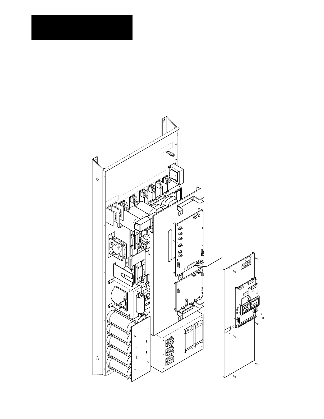
Page 6
Preface
Manual Objective (cont.) Firmware versions are marked at two locations in the drive – on the Main
Control Board and on the Base Driver/Power Supply Board.
For all drive ratings, the microprocessor chip U14 located on the Main
Control Board has the following firmware identification:
•P/N XXXXXXV1.01 –– Firmware Version 1.01.
•P/N XXXXXXV1.10 –– Firmware Version 2.01.
CAUTION
HAZARDOUS VOLTAGE ON CAPACITORS
WHEN NEON LIGHT IS ON. REMOVE POWER
AND WAIT 60 SECONDS BEFORE SERVICING.
ATTENTION
TENSION DANGEREUSE AU NIVEAU DES
CONDENSATEURS QUAND LES NEONS SONT
ALLUMES. COUPER LE COURANT ET
ATTENDRE 60 SECONDES AVANT DE
COMMENCER L'ENTRETIEN.
VORSICHT
AN DEN KONDENSATOREN BESTEHT
HOCHSPANNUNGSGEFAHR, WENN DS NEON-
LICHT AUFLECUDHTET. STROM UNTER-
BRECHEN UND 60 SEK. WARTEN BEVOR
SERVICEARBEITEN DURCHGEFÜHRT WERDEN.
ATTENZIONE
TENSIONE PERICOLOSA SUI CONDENSATORI
QUANDO LA LUCE AL NEON È ACCESA.
TOGLIERE L'ALIMENTAZIONE ED ASPETTARE 60
¿¬|– [¥
SECONDI PRIMA DI PRESTARE MANUTENZIONE.
†[Ÿ Ÿº |]º] ¬Ÿ[ ¿|] Ÿº][, <|>/º ¥‡º
¬Ÿ[ ¿|]
~|[º ¥‡º Ÿº][ <|>/º ¿Ÿº¿|]
|]º] ¬Ÿ[ ¿|] Ÿº][, <|>/º ¥‡º<|>/º ¥‡º
PRECAUCION
AVOLTAJE PERLIGROSO EN LS CAPACITORES
CUANDO LA LUZ DE NEON ESTÉ ENCENDIO.
ANTES DE DAR SERVICIO.
CORTE LA ENERGIA Y ESPERE 60 DEGUNDOS
GND
GND
CAUTION
HAZARDOUS VOLTAGE ON
CAPACITORS WHEN NEON
LIGHT IS ON. REMOVE POWER
AND WAIT 60 SEC. BEFORE
SERVICING.
BULLETIN 1336VT ADJUSTABLE FREQUENCY AC DRIVE
Microprocessor Chip U14
Located on Main Control Board
C1
➁
➀
SW1
C2
R
P
Freq
18
17
L3
L2
L1
M3
M2
M1
–DC
+DC
1
8
7
6
5
4
3
2
16
15
14
13
12
11
10
9
Jog
Start
Stop
Enter
R
P
P-2
Page 7
Preface
Manual Objective (cont.) For 5-52Amp ratings, microprocessor chip U21 located on the Base
Driver/Power Supply Board has the following firmware identification:
•P/N XXXXXXV1.01 –– Firmware Version 1.14.
•P/N XXXXXXV1.11 –– Firmware Version 2.01.
•P/N XXXXXXV3.01 –– Firmware Version 3.01.
CAUTION
HAZARDOUS VOLTAGE ON CAPACITORS
WHEN NEON LIGHT IS ON. REMOVE POWER
AND WAIT 60 SECONDS BEFORE SERVICING.
ATTENTION
TENSION DANGEREUSE AU NIVEAU DES
CONDENSATEURS QUAND LES NEONS SONT
ALLUMES. COUPER LE COURANT ET
ATTENDRE 60 SECONDES AVANT DE
COMMENCER L'ENTRETIEN.
VORSICHT
AN DEN KONDENSATOREN BESTEHT
HOCHSPANNUNGSGEFAHR, WENN DS NEON-
LICHT AUFLECUDHTET. STROM UNTERBRECHEN UND 60 SEK. WARTEN BEVOR
SERVICEARBEITEN DURCHGEFÜHRT WERDEN.
ATTENZIONE
TENSIONE PERICOLOSA SUI CONDENSATORI
QUANDO LA LUCE AL NEON È ACCESA.
TOGLIERE L'ALIMENTAZIONE ED ASPETTARE 60
¿¬|– [¥
SECONDI PRIMA DI PRESTARE MANUTENZIONE.
†[Ÿ Ÿº |]º] ¬Ÿ[ ¿|] Ÿº][, <|>/º ¥‡º
¬Ÿ[ ¿|]
~|[º ¥‡º Ÿº][ <|>/º ¿Ÿº¿|]
|]º] ¬Ÿ[ ¿|] Ÿº][, <|>/º ¥‡º<|>/º ¥‡º
PRECAUCION
AVOLTAJE PERLIGROSO EN LS CAPACITORES
CUANDO LA LUZ DE NEON ESTÉ ENCENDIO.
ANTES DE DAR SERVICIO.
CORTE LA ENERGIA Y ESPERE 60 DEGUNDOS
Microprocessor Chip U21
Located on Base Driver/Power Supply Board
CAUTION
HAZARDOUS VOLTAGE ON
CAPACITORS WHEN NEON
LIGHT IS ON. REMOVE POWER
AND WAIT 60 SEC. BEFORE
SERVICING.
BULLETIN 1336VT ADJUSTABLE FREQUENCY AC DRIVE
C1
➁
➀
SW1
C2
R
P
Freq
L3
L2
L1
M3
M2
M1
–DC
+DC
GND
GND
1
Jog
Start
Stop
13
12
11
10
9
8
7
6
5
4
3
2
Enter
R
P
18
17
16
15
14
P-3
Page 8
Preface
Manual Objective (cont.) For 65-77Amp ratings, microprocessor chip U2 located on the Base
Driver/Power Supply Board has the following firmware identification:
•P/N XXXXXXV1.14 –– Firmware Version 1.14.
•P/N XXXXXXV2.01 –– Firmware Version 2.01.
•P/N XXXXXXV3.01 –– Firmware Version 3.01.
GND
L3
L2
L1
M3
M2
TIGHTENING TORQE 120 INCH POUNDS
M1
USE 75°C COPPER WIRE ONLY WIRE RANGE 2/0 – 6 AWG
–DC
+DC
GND
–
M
+
CAUTION
HAZARDOUS VOLTAGE ON CAPACITORS
WHEN NEON LIGHT IS ON. REMOVE POWER
AND WAIT 60 SECONDS BEFORE SERVICING.
ATTENTION
TENSION DANGEREUSE AU NIVEAU DES
CONDENSATEURS QUAND LES NEONS SONT
ALLUMES. COUPER LE COURANT ET
ATTENDRE 60 SECONDES AVANT DE
COMMENCER L'ENTRETIEN.
VORSICHT
AN DEN KONDENSATOREN BESTEHT
HOCHSPANNUNGSGEFAHR, WENN DS NEON-
LICHT AUFLECUDHTET. STROM UNTER-
BRECHEN UND 60 SEK. WARTEN BEVOR
SERVICEARBEITEN DURCHGEFÜHRT WERDEN.
ATTENZIONE
TENSIONE PERICOLOSA SUI CONDENSATORI
QUANDO LA LUCE AL NEON È ACCESA.
TOGLIERE L'ALIMENTAZIONE ED ASPETTARE 60
¿¬|– [¥
SECONDI PRIMA DI PRESTARE MANUTENZIONE.
†[Ÿ Ÿº |]º] ¬Ÿ[ ¿|] Ÿº][, <|>/º ¥‡º
¬Ÿ[ ¿|]
~|[º ¥‡º Ÿº][ <|>/º ¿Ÿº¿|]
|]º] ¬Ÿ[ ¿|] Ÿº][, <|>/º ¥‡º<|>/º ¥‡º
PRECAUCION
AVOLTAJE PERLIGROSO EN LS CAPACITORES
CUANDO LA LUZ DE NEON ESTÉ ENCENDIO.
ANTES DE DAR SERVICIO.
CORTE LA ENERGIA Y ESPERE 60 DEGUNDOS
BULLETIN 1336VT ADJUSTABLE FREQUENCY AC DRIVE
Start
Stop
8
7
6
5
4
3
2
1
CAUTION
HAZARDOUS VOLTAGE ON
CAPACITORS WHEN NEON
LIGHT IS ON. REMOVE POWER
AND WAIT 60 SEC. BEFORE
SERVICING.
Microprocessor Chip U2
C1
➁
Located on Base Driver/Power Supply Board
➀
SW1
C2
R
P
Freq
Enter
R
P
Jog
18
17
16
15
14
13
12
11
10
9
CAUTION
HAZARDOUS VOLTAGE ON
CAPACITORS WHEN NEON
LIGHT IS ON. REMOVE POWER
AND WAIT 60 SEC. BEFORE
SERVICING.
P-4
Page 9
Preface
Manual Objective (cont.) For 96-180Amp ratings, microprocessor chip U2 located on the Base
Driver/Power Supply Board has the following firmware identification:
•P/N XXXXXXV1.14 –– Firmware Version 1.14.
•P/N XXXXXXV2.01 –– Firmware Version 2.01.
•P/N XXXXXXV3.01 –– Firmware Version 3.01.
GND
L3
L2
L1
M3
TIGHTENING TORQUE 275 INCH POUNDS
M2
USE 75°C COPPER WIRE ONLY WIRE RANGE 350 MCM –– 6 AWG
M1
– DC
+ DC
–
M
+
–
M
+
CAUTION
HAZARDOUS VOLTAGE ON
CAPACITORS WHEN NEON
LIGHT IS ON. REMOVE POWER
AND WAIT 60 SEC. BEFORE
CAUTION
HAZARDOUS VOLTAGE ON CAPACITORS
WHEN NEON LIGHT IS ON. REMOVE POWER
AND WAIT 60 SECONDS BEFORE SERVICING.
ATTENTION
TENSION DANGEREUSE AU NIVEAU DES
CONDENSATEURS QUAND LES NEONS SONT
ALLUMES. COUPER LE COURANT ET
ATTENDRE 60 SECONDES AVANT DE
COMMENCER L'ENTRETIEN.
VORSICHT
AN DEN KONDENSATOREN BESTEHT
HOCHSPANNUNGSGEFAHR, WENN DS NEON-
LICHT AUFLECUDHTET. STROM UNTER-
BRECHEN UND 60 SEK. WARTEN BEVOR
SERVICEARBEITEN DURCHGEFÜHRT WERDEN.
ATTENZIONE
TENSIONE PERICOLOSA SUI CONDENSATORI
QUANDO LA LUCE AL NEON È ACCESA.
TOGLIERE L'ALIMENTAZIONE ED ASPETTARE 60
¿¬|– [¥
SECONDI PRIMA DI PRESTARE MANUTENZIONE.
†[Ÿ Ÿº |]º] ¬Ÿ[ ¿|] Ÿº][, <|>/º ¥‡º
¬Ÿ[ ¿|]
~|[º ¥‡º Ÿº][ <|>/º ¿Ÿº¿|]
|]º] ¬Ÿ[ ¿|] Ÿº][, <|>/º ¥‡º<|>/º ¥‡º
PRECAUCION
AVOLTAJE PERLIGROSO EN LS CAPACITORES
CUANDO LA LUZ DE NEON ESTÉ ENCENDIO.
ANTES DE DAR SERVICIO.
CORTE LA ENERGIA Y ESPERE 60 DEGUNDOS
SERVICING.
–
M
+
3
2
1
BULLETIN 1336VT ADJUSTABLE FREQUENCY AC DRIVE
Start
Stop
8
7
6
5
4
CAUTION
HAZARDOUS VOLTAGE ON
CAPACITORS WHEN NEON
LIGHT IS ON. REMOVE POWER
AND WAIT 60 SEC. BEFORE
SERVICING.
Jog
11
10
9
C1
➁
➀
SW1
C2
R
P
Freq
Enter
R
P
18
17
16
15
14
13
12
Microprocessor Chip U2
Located on Base Driver/Power Supply Board
P-5
Page 10
Preface
Manual Objective (cont.) For 240-300Amp ratings, microprocessor chip U2 located on the Base
Driver/Power Supply Board has the following firmware identification:
•P/N XXXXXXV1.14 –– Firmware Version 1.14.
•P/N XXXXXXV2.01 –– Firmware Version 2.01.
•P/N XXXXXXV3.01 –– Firmware Version 3.01.
USE 75°C COPPER WIRE ONLY.
WIRE SIZE 2 (3) AWG
GND
TIGHTENING TORQUE 275 INCH POUNDS
L3
L2
L1
USE 75°C COPPER WIRE ONLT.
WIRE RANGE 500 MCM –– 0 AWG
TIGHTENING TORQUE 375 INCH POUNDS
M3
M2
GND
M1
USE 75°C COPPER WIRE ONLT.
– DC
WIRE RANGE 350 MCM –– 6 AWG
TIGHTENING TORQUE 275 INCH POUNDS
+ DC
P-6
CAUTION
HAZARDOUS VOLTAGE ON CAPACITORS
WHEN NEON LIGHT IS ON. REMOVE POWER
AND WAIT 60 SECONDS BEFORE SERVICING.
ATTENTION
TENSION DANGEREUSE AU NIVEAU DES
CONDENSATEURS QUAND LES NEONS SONT
ALLUMES. COUPER LE COURANT ET
ATTENDRE 60 SECONDES AVANT DE
COMMENCER L'ENTRETIEN.
VORSICHT
AN DEN KONDENSATOREN BESTEHT
HOCHSPANNUNGSGEFAHR, WENN DS NEON-
LICHT AUFLECUDHTET. STROM UNTERBRECHEN UND 60 SEK. WARTEN BEVOR
SERVICEARBEITEN DURCHGEFÜHRT WERDEN.
ATTENZIONE
TENSIONE PERICOLOSA SUI CONDENSATORI
QUANDO LA LUCE AL NEON È ACCESA.
TOGLIERE L'ALIMENTAZIONE ED ASPETTARE 60
¿¬|– [¥
SECONDI PRIMA DI PRESTARE MANUTENZIONE.
†[Ÿ Ÿº |]º] ¬Ÿ[ ¿|] Ÿº][, <|>/º ¥‡º
¬Ÿ[ ¿|]
~|[º ¥‡º Ÿº][ <|>/º ¿Ÿº¿|]
|]º] ¬Ÿ[ ¿|] Ÿº][, <|>/º ¥‡º<|>/º ¥‡º
PRECAUCION
AVOLTAJE PERLIGROSO EN LS CAPACITORES
CUANDO LA LUZ DE NEON ESTÉ ENCENDIO.
ANTES DE DAR SERVICIO.
CORTE LA ENERGIA Y ESPERE 60 DEGUNDOS
Microprocessor Chip U2
Located on Base Driver/Power Supply Board
CAUTION
HAZARDOUS VOLTAGE ON
CAPACITORS WHEN NEON
LIGHT IS ON. REMOVE POWER
AND WAIT 60 SEC. BEFORE
SERVICING.
2
1
BULLETIN 1336VT ADJUSTABLE FREQUENCY AC DRIVE
6
5
4
3
CAUTION
HAZARDOUS VOLTAGE ON
CAPACITORS WHEN NEON
LIGHT IS ON. REMOVE POWER
AND WAIT 60 SEC. BEFORE
SERVICING.
C1
➁
➀
SW1
C2
R
P
Freq
Enter
R
P
Jog
Start
Stop
18
17
16
15
14
13
12
11
10
9
8
7
Page 11

Preface
Manual Objective (cont.) This manual is meant to guide the user with interface, installation, setup
and troubleshooting of a 1336VT. The contents are arranged in order from
a general description to troubleshooting and maintenance. To assure
successful installation and operation, the material presented must be
thoroughly read and understood before proceeding. Particular attention
must be directed to the Caution, Warning and Important statements
contained within.
Important Information about this Manual
This manual has been prepared primarily to support this product in a single
application. It is a standard document that is intended to help the user
understand the individual operating characteristics and limitations of this
equipment including hazards associated with installation and setup
procedures. Note the following points:
•This equipment has been designed to meet the requirements of a
component in an integrated system.
•It must be noted that special considerations are to be given to
characteristics of other peripheral solid-state control equipment and the
cumulative impact on safety.
•Manufacturers and engineering groups responsible for specification or
design of electrical control equipment must refer to applicable industry
standards and codes for specific safety guidelines and interface
requirements.
•In the actual factory environment, the user is responsible to assure
compliance with applicable machine and operator safety codes or
regulations which are beyond the scope and purpose of this document.
P-7
Page 12

Preface
General Precautions In addition to the precautions listed throughout this manual, the following
statements which are general to the system must be read and understood.
ATTENTION: Only personnel familiar with the 1336VT AC
Drive and associated machinery should plan or implement the
!
installation, start-up and subsequent maintenance of the system.
Failure to comply may result in personal injury and/or equipment
damage.
ATTENTION: This assembly may contain parts and
sub-assemblies that are sensitive to electrostatic discharge. Static
!
control precautions are required when testing, servicing or
repairing this assembly. Component damage may result if you
ignore electrostatic discharge control procedures. If you are not
familiar with static control procedures, reference Allen-Bradley
Publication 8000-4.5.2, Guarding Against Electrostatic Damage or
any other applicable ESD protection handbook.
ATTENTION: An incorrectly applied or installed system can
result in component damage or reduction in product life. Wiring or
!
application errors, such as undersizing the motor, incorrect or
inadequate AC supply, or excessive ambient temperatures may
result in malfunction of the system.
P-8
Page 13

Chapter
1
PreInstallation Care
Before installing and operating your 1336VT, carefully read this manual
and observe all precautions. The catalog number of your drive as explained
in Chapter 2 — Drive and Option Identification lists the drive rating, type
of enclosure, nominal line voltage, phase and frequency, as well as any
additional options that you may have specified. Specifications for all drives
including standard controls, adjustment range, diagnostics and
environmental qualifications are listed in Chapter 4 — Specifications.
Receiving Once you have received your drive, careful inspection for shipping damage
must be made. Damage to the shipping carton is usually a good indication
that it has received improper handling. Any and all damage should be
immediately reported to the freight carrier and your nearest Allen-Bradley
Area Sales/Support Center.
Carefully unpack the drive, taking care to save the shipping carton and any
packing material should return be necessary. Verify that the items on the
packing list or bill of lading agree with your order.
Storage If the drive will not immediately be installed, it should be stored in a clean,
dry area where the ambient temperature is not less than -40°C nor more
than +85°C. The drive must not be stored in a corrosive environment nor
subject to conditions in excess of the storage environment parameters
stated in Chapter 4 — Specifications.
Handling Depending upon the rating and options ordered, the weight of your drive
can vary. To guard against injury to personnel, proper safety precautions
and practices must be observed whenever the drive is being moved from
one location to another.
Shipping The carton and materials that came with your drive have been designed and
tested to provide reasonable protection against damage during transit.
Should the drive be shipped to another location, it is recommended that the
original shipping carton and packing material be used to protect the drive
from damage in transit.
1-1
Page 14

Chapter 1
Pre-Installation Care
ATTENTION: This assembly contains parts and sub-assemblies
that are sensitive to electrostatic discharge. Static control
!
precautions are required when servicing this assembly. Component
damage may result if you ignore electrostatic discharge control
procedures. If you are not familiar with static control procedures,
reference Allen-Bradley Publication 8000-4.5.2, Guarding Against
Electrostatic Damage, or any other applicable ESD protection
handbook.
Electrostatic Discharge Electrostatic discharge generated by static electricity can damage the
Precautions complimentary metallic oxide semiconductor devices on various drive
boards. It is recommended that you perform these procedures to guard
against this type of damage when circuit boards are removed or installed:
• Wear a wrist type grounding strap that is grounded to the drive chassis.
• Attach the wrist strap before removing the new circuit board from the
conductive packet.
• Remove boards from the drive and immediately insert them into their
conductive packets.
1-2
Page 15

Chapter
2
Drive and Option Identification
The following is an explanation of the catalog numbering system for
1336VT Adjustable Frequency AC Drives and options. The catalog
number is coded to identify the drive power rating and can be found on the
drive shipping carton.
1336VT Drive Catalog Numbers
Bulletin Number
Drive Ratings A group of four characters coded to indicate input voltage and output
1336VT B 015 EAE FA2 L2 S1
Bulletin Drive Enclosure Options Options Options
Number Rating Type
The Allen-Bradley reference number identifying the type or family of
products.
power rating.
The first character indicates the input voltage range of the drive.
Drives with a code “B” are suitable for operating from any one of the
following voltage inputs: 380/415/460V AC, 50/60 Hz, 3-phase.
Fan Transformer Reconnection for Alternate Drive Input Voltages
Important:
For drives rated 5-52 Amp, reconnection of Fan Transformer T1 is not
necessary.
For drives rated 65-300 Amp, Fan Transformer T1 must be reconnected for
380 or 415V operation. If Fan Transformer T1 is not connected to match
the incoming voltage, overtemperature fault F08 may occur. Refer to
Chapter 6 for wiring details.
2-1
Page 16

Chapter 2
Drive and Option Identification
The second, third and fourth characters indicate the power rating of the
drive, as shown in Table 2.1.
Table
2.1 - 1336VT Output Current and kV
Rating Amp kVA Out kVA Out kVA Out
Code Out 380V AC 415V AC 460V AC
003 5.0 3.3 3.6 4.0
005 8.0 5.3 5.8 6.4
007 11.0 7.2 7.9 8.8
010 14.0 9.2 10.1 11.2
015 21.0 13.8 15.1 16 .7
020 27.0 17.8 19.4 21 .5
025 34.0 22.4 24.4 27 .1
030 40.0 26.3 28.8 31 .9
040 52.0 34.2 37.4 41 .4
050 65.0 42.8 46.7 51 .8
060 77.0 50.7 55.3 61 .3
075 96.0 63.2 69.0 76 .5
100 124.0 81.6 89 .1 98.8
125 156.0 102.7 112.1 124.3
150 180.0 118.5 129.4 143.4
200 240.0 158.0 172.5 191.2
250 300.0 197.4 215.6 239.0
A
Drive Enclosure Type The first character “E” indicates enclosure code.
The second character indicates the type of enclosure as initially shipped
from the factory.
O –– Open style (IP00)
A –– NEMA Type 1 (IP20)
The third character indicates enclosure size by amp rating.
N –– 5.0, 8.0, 11.0, 14.0 or 21.0 Amp ratings
P –– 27.0 or 34.0 Amp ratings
R –– 40.0 or 52.0 Amp ratings
S –– 65.0 or 77.0 Amp ratings
T –– 96.0, 124.0, 156.0 or 180.0 Amp ratings
W –– 240.0 or 300.0 Amp ratings
Factory Installed Options All additional characters indicate drive options that were initially installed
at the factory. Each option code is added to the catalog number and
separated by a hyphen.
2-2
Page 17

Chapter
3
Overview
The 1336VT is a microprocessor controlled, high performance, adjustable
frequency drive designed to control three phase induction motors on
critical industrial applications. The drive produces a three phase, PWM,
adjustable frequency output to supply an adjustable motor speed. The drive
output voltage is a function of output frequency and is adjustable to match
motor parameters to obtain optimum motor performance.
To help achieve precise and repeatedly accurate control, setup and
operation, the 1336VT is digitally programmable. The drive may be
programmed from a Local or Remote Control Panel or through the Serial
Communication Port using optional devices.
Depending upon your configuration, various status and fault conditions are
reported either through the Programming and Display Panel or through the
Serial Communications Port. All fault diagnostics start with both load and
drive self-check diagnostics each time the drive is powered up. While
running, the drive continues to monitor potential fault conditions. To allow
real-time preventive maintenance, parameters such as drive output current
and control conditions can be monitored even while the drive is running.
Should a fault occur, detailed diagnostic codes isolate the problem to
identify the condition, allowing quick, corrective action to be taken to
restore process control.
3-1
Page 18
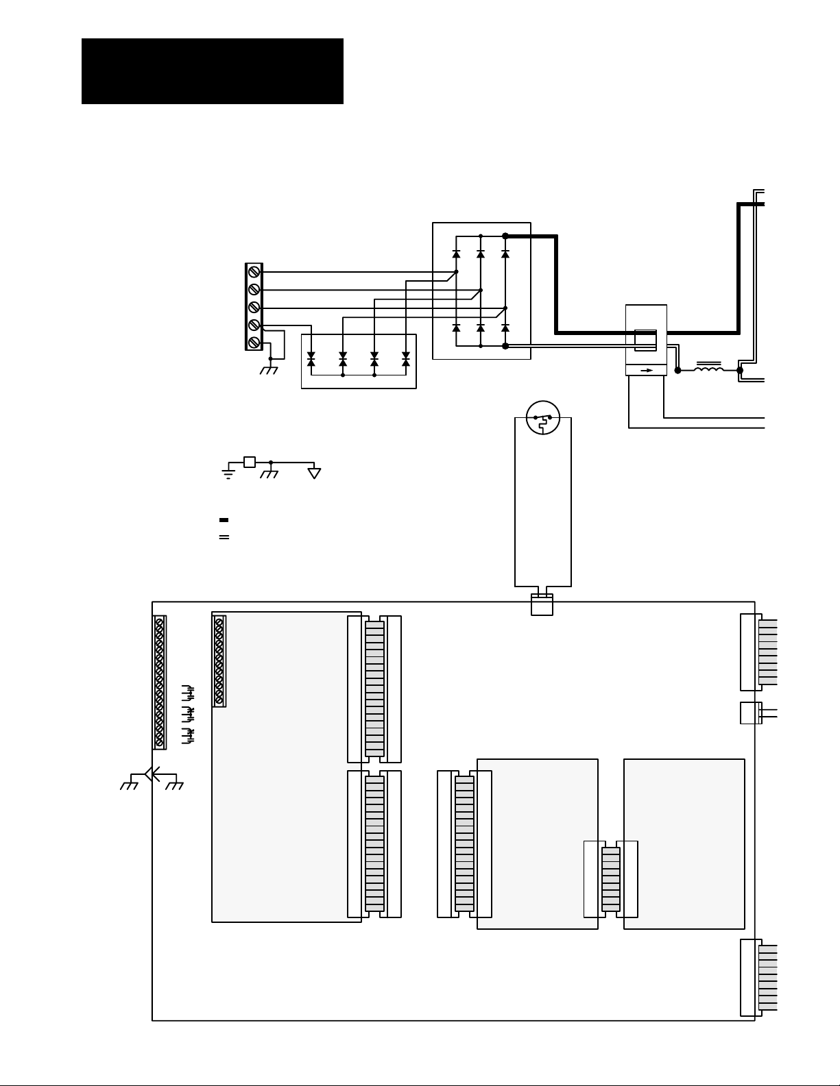
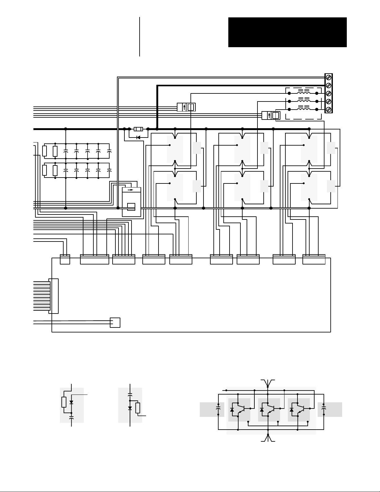
Chapter 3
Overview
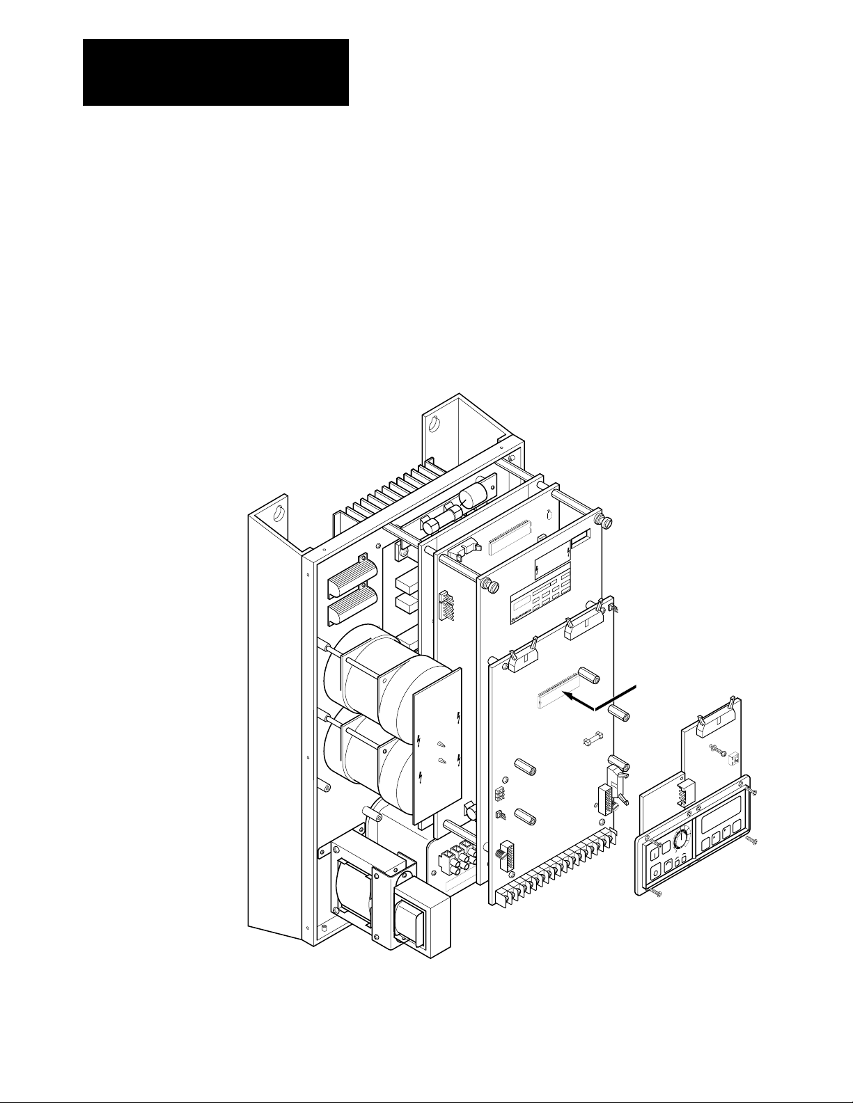
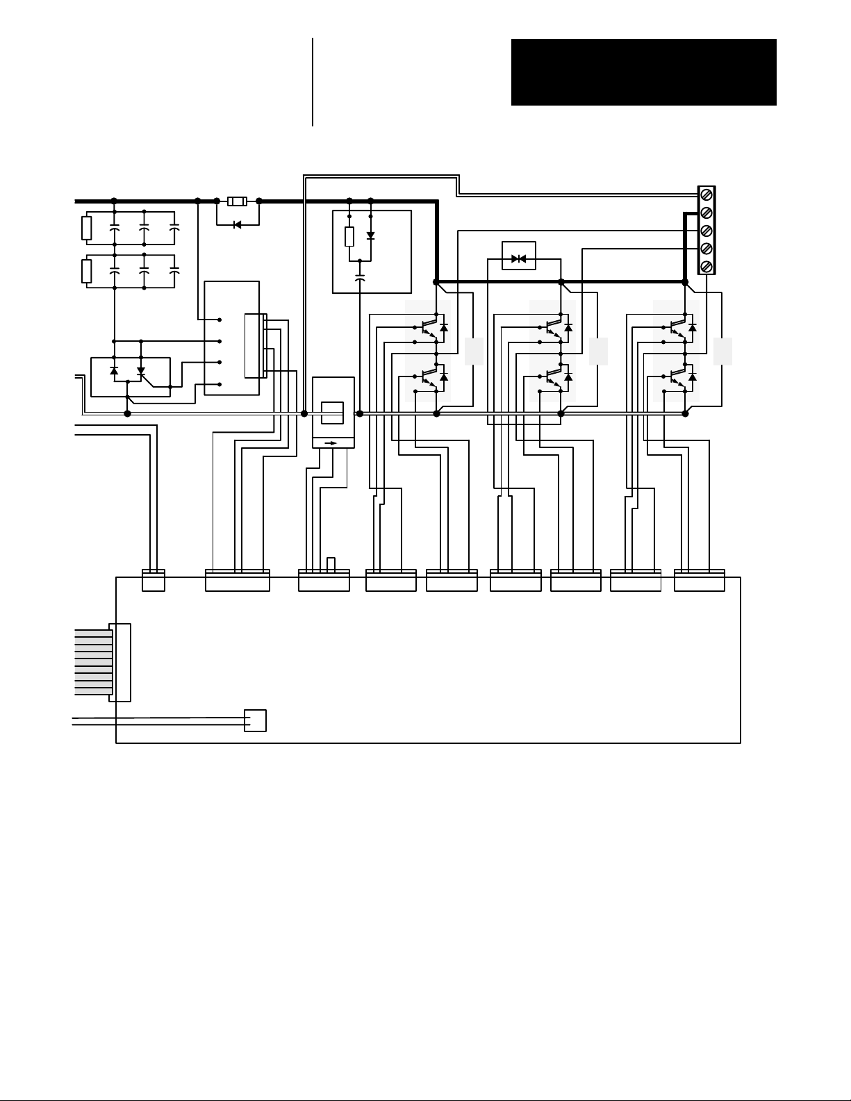
Figure
3.1 - 1336VT 552 Amp Unit Schematic
L1
L2
L3
GND
GND
GND
TB1
4 3 2 1
MOV1
BR1
+
1
2
3
–
ST
12
GND
Sense
(AC)
L1
13
21
EARTH
GROUND
CHASSIS
GROUND
SIGNAL
COMMON
+ BUS
– BUS
1
1
TB2
2
3
4
5
6
7
8
9
10
11
12
13
14
15
16
17
18
E1
19
TB1
20
21
22
23
24
25
26
27
28
29
30
J1
J2
Optional +5V DC TTL
Logic Interface
or
Optional 24V DC Logic
Interface
or
Optional 115V AC Logic
Interface
1
10
11
12
13
14
15
16
17
18
19
1
10
11
12
13
14
15
16
17
18
19
2
3
4
5
6
7
8
9
20
2
3
4
5
6
7
8
9
20
J8
J9 J2
1
1
2
2
3
3
4
4
5
5
6
6
7
7
8
8
9
9
10
10
11
11
12
12
13
13
14
14
15
15
16
16
17
17
18
18
19
19
20
20
2
3
4
5
6
7
8
9
10
11
12
13
14
15
16
17
18
19
20
1
2
3
4
5
6
7
8
9
10
11
12
13
14
15
16
17
18
19
20
12
J6
Main Control Board
J1
Programming and
Display Board
(LOCAL DIS)
(MAIN CTL)
J2
1
2
3
4
5
6
7
8
9
10
Optional Logic
J1
1
2
3
4
5
6
7
8
9
10
Control Board
(LOCAL CTL)
J1
1
2
3
4
5
6
7
8
9
10
1
J7
2
3-2
Remote
Serial
Communicatio
Options
For
J4
1
2
3
4
5
6
7
8
ns
9
10
Page 19
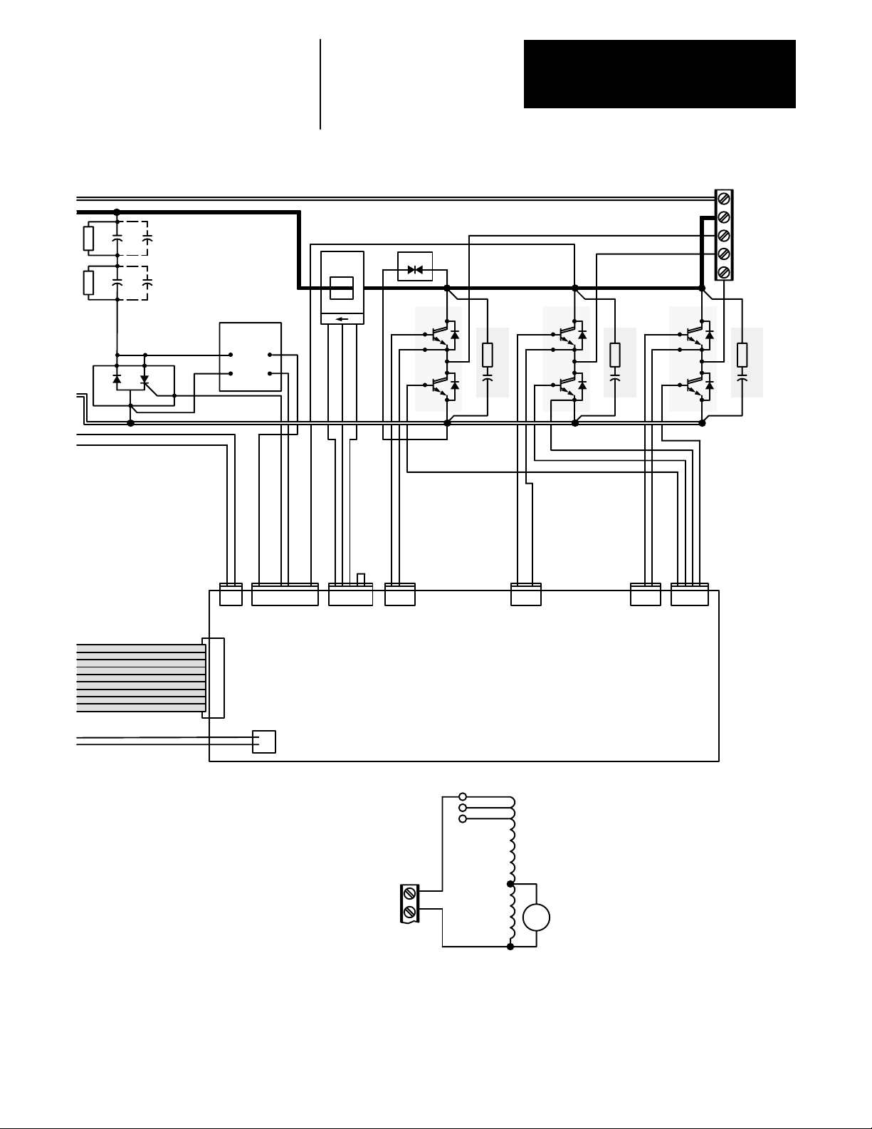
Chapter 3
Overview
Note:1C2 & 2C2 – 40 & 52 Amp Drives
Only
R1 1C1
R2 2C1
M1
1C2
2C2
KA
G2
AK
Bus
Sense
(AC)
+–
Precharge
J7–1
M1–K
M1–AK
J7–5
Board
21
12345678 12345 123 123 1234123
MOV2
2
1
Q1
C1 C1 C1
B1
E1
B2
E2
1
SN1
C2
E1
2
Q2
B1
E1
B2
E2
1
SN2
C2
E1
2
J8 J7 J6 J5 J4 J3 J2
Q3
TB1
– DC
+ DC
M1
M2
M3
B1
E1
B2
E2
1
SN3
C2
E1
2
1
J1
2
3
4
5
6
7
8
9
10
Transformer
1
2
T2
Base Driver/Power Supply Board
(BASEDR/PWRSPLY)
AC
Not Used
Not Used
T1
TB1
L1
L2
Chassis Fan
14-52 Amp Drives
Fan
3-3
Page 20
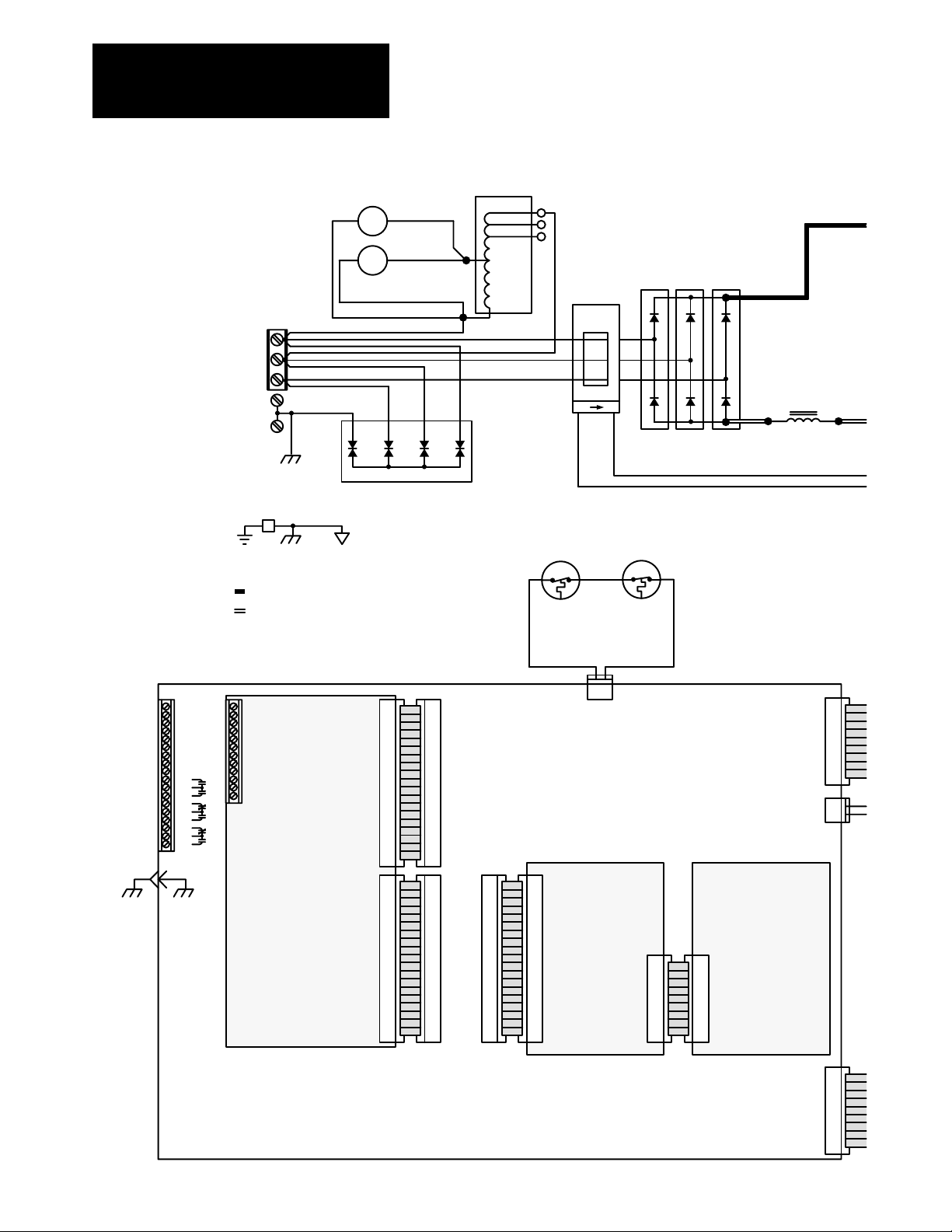
Chapter 3
Overview
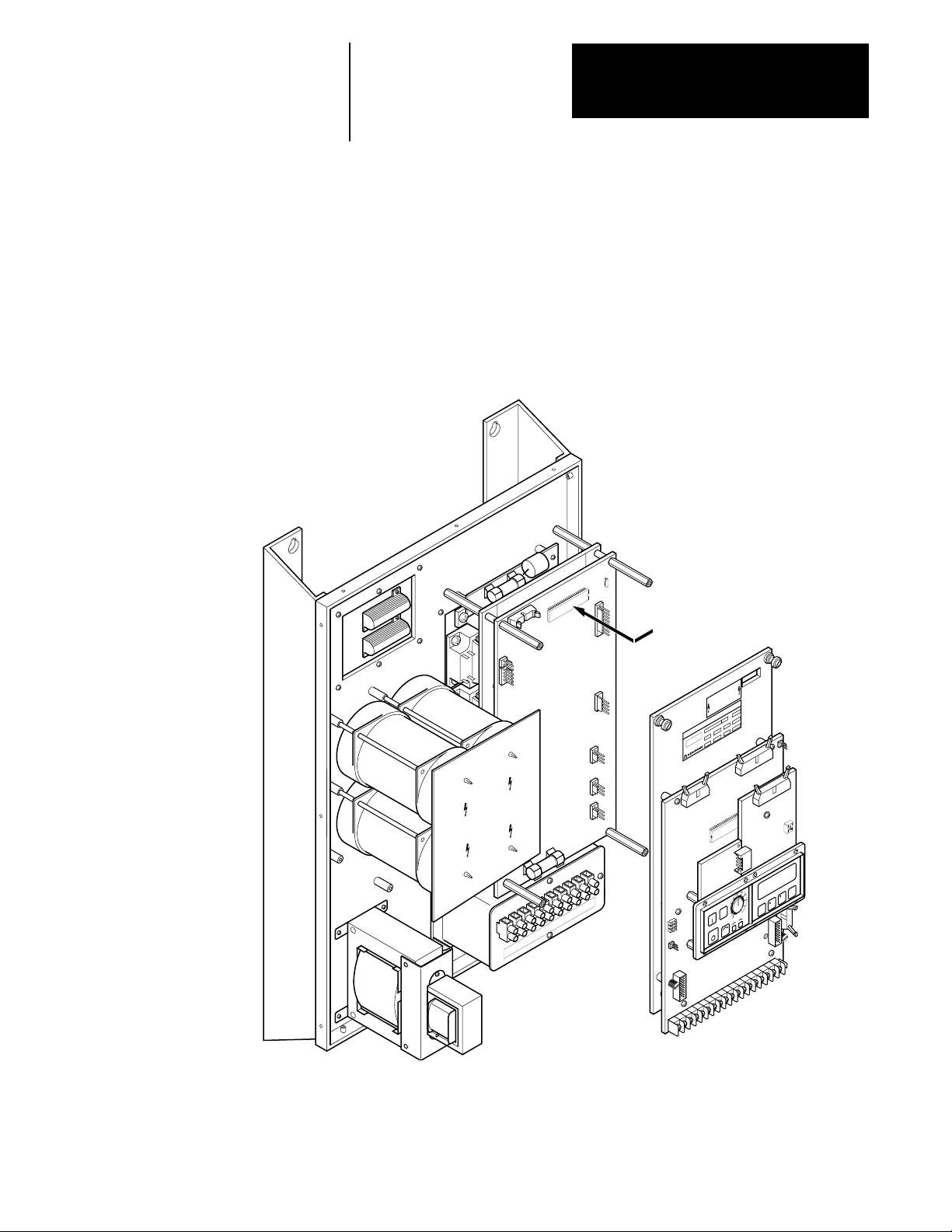
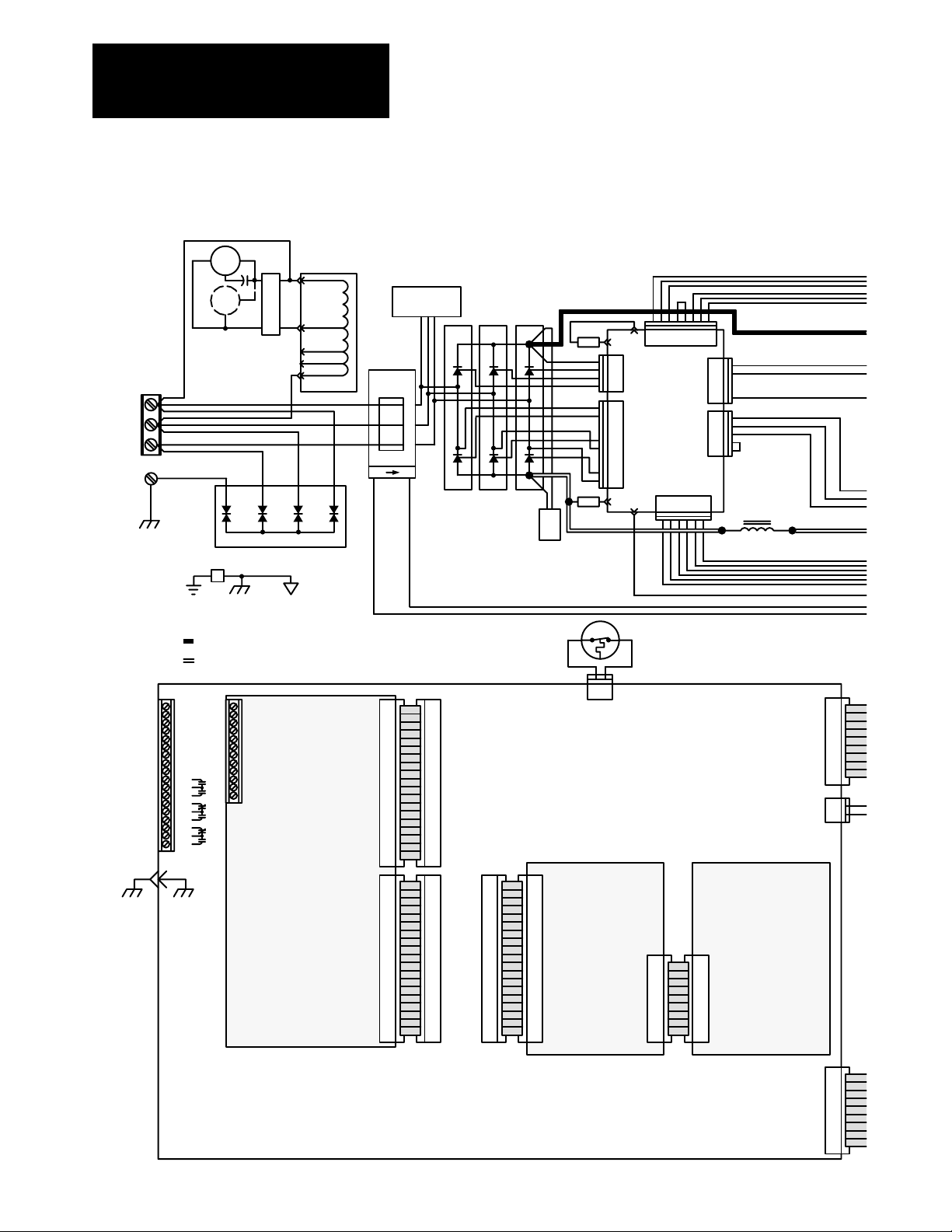
Figure
3.2 - 1336VT 65 and 77 Amp Unit Schematic
L1
L2
L3
GND
GND
EARTH
GROUND
GND
+ BUS
– BUS
TB1
CHASSIS
GROUND
1 2 120V AC
Fan 1
1 2 120V AC
Fan 2
MOV1
SIGNAL
COMMON
460V AC
415V AC
380V AC
T1
GND
Sense
+
+
+
1
2
3
(AC)
21
4321
ST1
12
–
BR1 BR2 BR3
ST2
12
–
–
L1
13
1
1
TB2
2
3
4
5
6
7
8
9
10
11
12
13
14
15
16
17
18
E1
19
TB1
20
21
22
23
24
25
26
27
28
29
30
J1
J2
Optional +5V DC TTL
Logic Interface
or
Optional 24V DC Logic
Interface
or
Optional 115V AC Logic
Interface
1
10
11
12
13
14
15
16
17
18
19
1
10
11
12
13
14
15
16
17
18
19
2
3
4
5
6
7
8
9
20
2
3
4
5
6
7
8
9
20
J8
J9 J2
1
1
2
2
3
3
4
4
5
5
6
6
7
7
8
8
9
9
10
10
11
11
12
12
13
13
14
14
15
15
16
16
17
17
18
18
19
19
20
20
2
3
4
5
6
7
8
9
10
11
12
13
14
15
16
17
18
19
20
1
2
3
4
5
6
7
8
9
10
11
12
13
14
15
16
17
18
19
20
12
J6
Main Control Board
J1
Programming and
Display Board
(LOCAL DIS)
(MAIN CTL)
J2
1
2
3
4
5
6
7
8
9
10
Optional Logic
Control Board
J1
1
2
3
4
5
6
7
8
9
10
(LOCAL CTL)
Communicatio
For
Remote
Serial
Options
J1
1
2
3
4
5
6
7
8
9
10
1
J7
2
J4
1
2
3
4
5
6
7
8
ns
9
10
3-4
Page 21
R1
R2
M1
1C1 1C2
2C1 2C2
KA
G2
AK
1C3
2C3
12
F1
D2
Precharge
J1
B+
M1–K
M1–G1
M1–AK
Board
Chapter 3
Overview
TB1
– DC
122
1
2
Bus
Snubber
1
Q3
1
2
3
4
5
6
7
8
Bus
Sense
(AC)
+–
C1
B1
C2
E1
B2
SN1
E1
E2
MOV2
2
1
Q2
C1
1
2
B1
E1
B2
E2
1
C2
SN2
E1
2
Q1
C1
B1
E1
B2
E2E2E2
E2
+ DC
M3
M2
M1
1
C2
SN3
E1
2
21
J8 J7
1
J1
2
3
4
5
6
7
8
9
10
12345678
1
2
123456J6123456J5123456
Base Driver/Power Supply Board
(BASEDR/PWRSPLY)
Transformer
T2
J10
123456J4123456J923456 123456
1
J3
J2
3-5
Page 22
Chapter 3
Overview
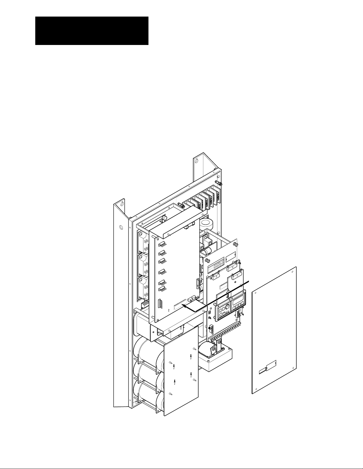
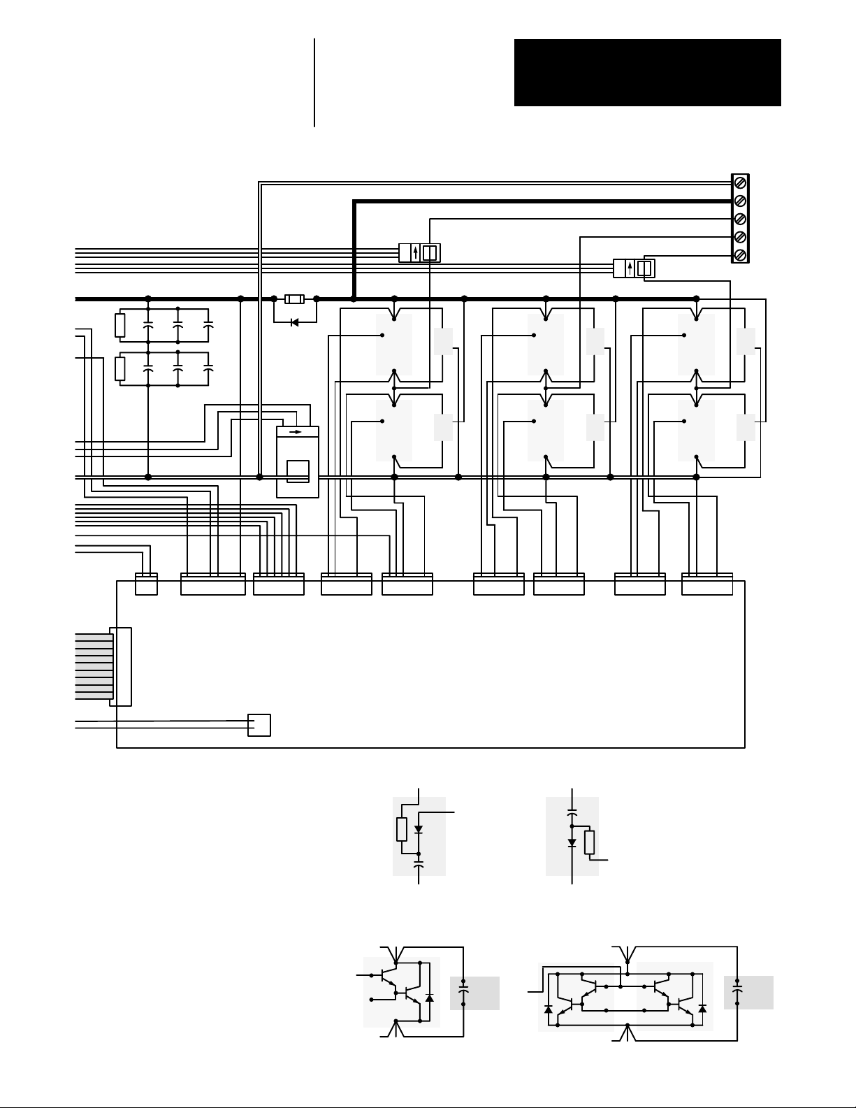
Figure
3.3 - 1336VT 96180 Amp Unit Schematic
Note:Aux Fan –
156 and 180 Amp Drives
Only
Fan
TB4
1
Aux
Fan
2
TB1
L1
L2
L3
GND
MOV1
GND
T1
120V AC
380V AC
415V AC
460V AC
Rectifie
r
Snubber
K1K1K1
G1
G1
GND
Sense
(AC)
21
4321
G1
K2
K2
K2
G2
G2
G2
BR1 BR2 BR3
SN7
R5
E2
E1
J8
4
3
2
1
J1
10
9
Precharge
8
Board
7
6
5
4
3
2
J2
1
R4
E3
E4
12345678
5
4
3
2
1
J7
5
4
3
2
1
J6
J5
123456
L1
12
EARTH
GROUND
1
TB2
2
3
4
5
6
7
8
9
10
11
12
13
14
15
16
17
18
E1
CHASSIS
GROUND
SIGNAL
COMMON
+ BUS
– BUS
19
TB3
20
21
22
23
24
25
26
27
28
29
30
Optional +5V DC TTL
Logic Interface
Optional 24V DC Logic
Interface
Optional 115V AC Logic
Interface
ST1
12
12
1
10
11
12
13
14
15
16
17
18
19
1
10
11
12
13
14
15
16
17
18
19
2
3
4
5
6
7
8
9
20
2
3
4
5
6
7
8
9
20
J8
J9 J2
J6
Main Control Board
(MAIN CTL)
1
1
2
2
3
3
4
5
6
7
8
9
10
11
12
13
14
15
16
17
18
19
20
Programming and
4
5
Display Board
6
7
(LOCAL DIS)
8
9
10
11
12
13
14
15
16
17
18
19
20
1
2
3
4
5
6
7
8
9
10
Optional Logic
Control Board
1
2
3
4
5
6
7
8
9
10
(LOCAL CTL)
1
2
3
4
5
6
7
8
9
10
11
12
13
14
15
16
17
18
19
20
1
2
3
4
5
6
or
or
7
8
9
10
11
12
13
14
15
16
17
18
19
20
1
J1
2
3
4
5
6
7
8
9
10
J7
1
2
3-6
For
Remote
Serial
Communicatio
Options
J4
1
2
3
4
5
6
7
8
ns
9
10
Page 23
R1R21C1 1C2
2C1 2C2
1C3
2C3
12
F1
D1
Chapter 3
Overview
TB1
– DC
+ DC
M1
LEM
A
+
–
C
B
X1
E
SN1
C
B
X3
E
SN3
LEM C
+
–
C
B
X5
E
M2
M3
SN5
21
J8 J7
J1
1
2
3
4
5
6
7
8
9
10
12345678
C
+–
BUS
Sense
(AC)
123456J6123456J5123456
B
X2
E
J10
Base Driver/Power Supply Board
(BASEDR/PWRSPLY)
Transformer
1
2
T2
+ BUS
SN2
123456J4123456
Snubber
Diagrams
C (X2, X4, X6)
C
B
X4
E
SN4
123456J3123456
J9
C (+ BUS)
C
B
X6
E
SN6
J2
E (– BUS)
SN2, SN4 & SN6 SN1, SN3 & SN5
X1–6
Output Transistor
Diagrams
C
B
B
B
X
E
96 and 124 Amp
1C4-6C4
B
– BUS
E (X1, X3, X5)
X1–6
C
EE
C
B
B
X
E
C
B
B
X
1C4-6C4
156 and 180 Amp
3-7
Page 24
Chapter 3
Overview
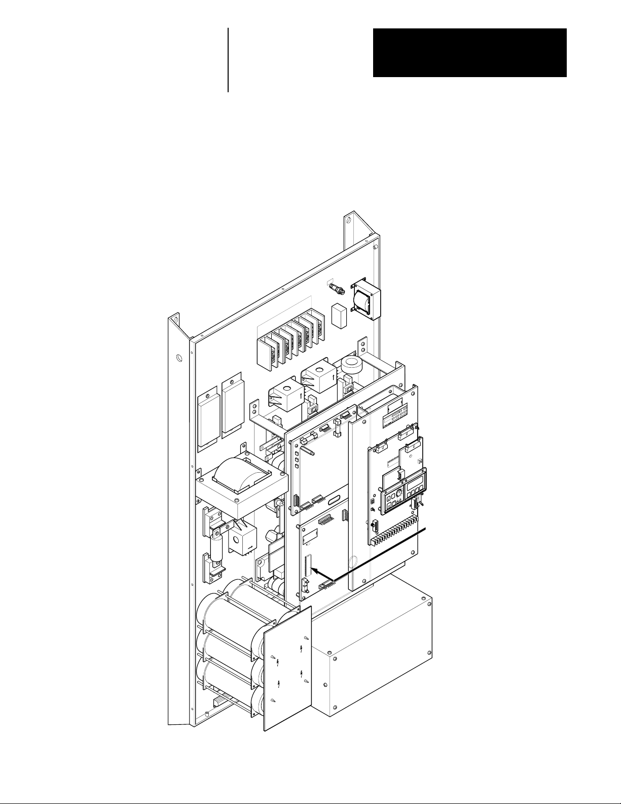
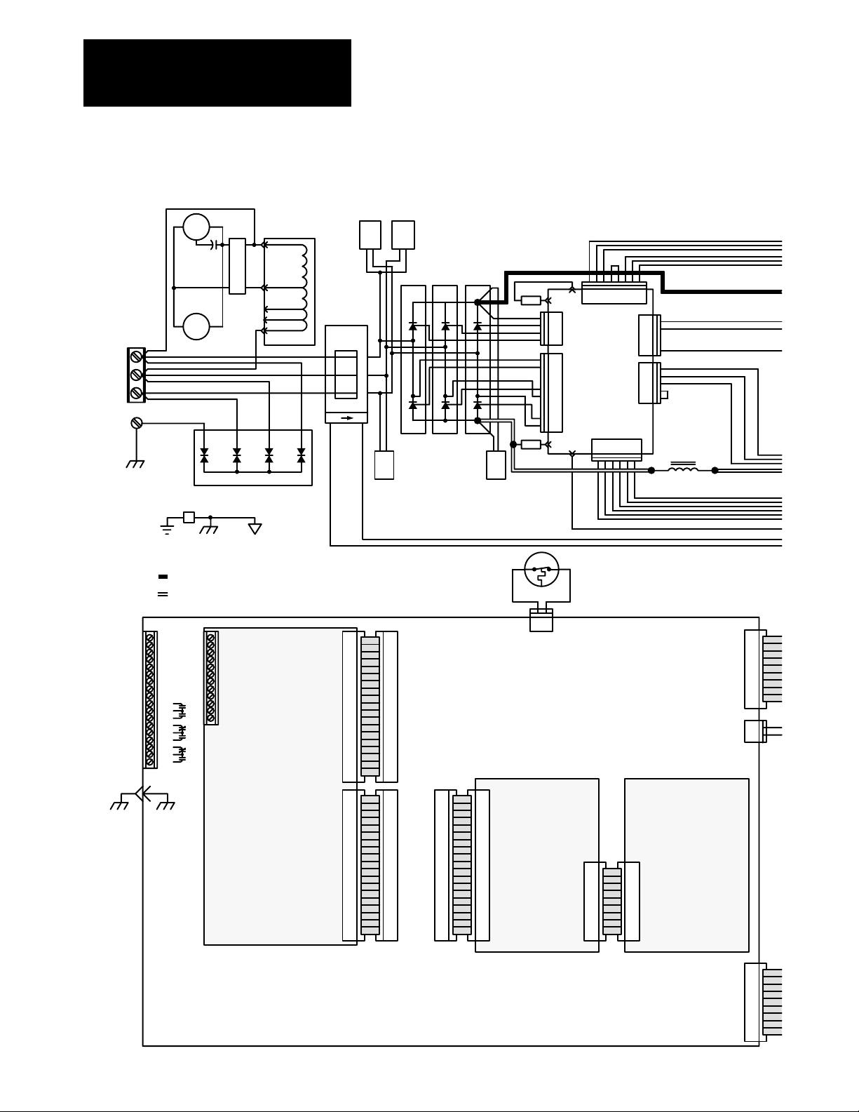
Figure
3.4 - 1336VT 240 and 300 Amp Unit Schematic
L1
L2
L3
GND
TB1
EARTH
GROUND
1
TB2
2
3
4
5
6
7
8
9
10
11
12
13
14
15
16
17
18
E1
Fan 1
TB4
1
2
Fan 2
MOV1
GND
CHASSIS
GROUND
SIGNAL
COMMON
+ BUS
– BUS
19
TB3
20
21
22
23
24
25
26
27
28
29
30
Optional +5V DC TTL
Logic Interface
Optional 24V DC Logic
Optional 115V AC Logic
T1
120V AC
380V AC
415V AC
460V AC
or
Interface
or
Interface
SN9 SN10
K1K1K1
G1
G1
GND
Sense
(AC)
21
4321
G1
K2
K2
K2
G2
G2
G2
BR1 BR2 BR3
SN8
J1
1
2
3
4
5
6
7
8
9
10
11
12
13
14
15
16
17
18
19
20
J2
1
2
3
4
5
6
7
8
9
10
11
12
13
14
15
16
17
18
19
20
1
2
3
4
5
6
7
8
9
10
11
12
13
14
15
16
17
18
19
20
1
2
3
4
5
6
7
8
9
10
11
12
13
14
15
16
17
18
19
20
J8
J9 J2
1
1
2
2
3
3
4
4
5
5
6
6
7
7
8
8
9
9
10
10
11
11
12
12
13
13
14
14
15
15
16
16
17
17
18
18
19
19
20
20
R7
R8
SN7
ST1
12
12
J6
Main Control Board
J1
Programming and
Display Board
(LOCAL DIS)
E2
E1
J8
4
3
2
1
J1
10
9
Precharge
8
Board
7
6
5
4
3
2
J2
1
E3
E4
(MAIN CTL)
J2 J1
10
12345678
5
4
3
2
1
J7
5
4
3
2
1
J6
J5
123456
L1
12
J1
J7
1
2
3
4
5
6
7
8
9
10
1
2
Optional Logic
Control Board
(LOCAL CTL)
1
1
2
2
3
3
4
4
5
5
6
6
7
7
8
8
9
9
10
3-8
1
J4
2
3
4
5
6
7
8
9
10
Page 25
R1
R2
R4
1C1 1C2 1C3
R5
2C1 2C2 2C3
1C4
2C4
1C5
2C5
F1
12
D1
+–
BUS
Sense
Chapter 3
Overview
TB1
– DC
12
LEM
A
+
–
C
B
X1
E
C
B
X2
E
SN1
SN2
C
B
X3
E
C
B
X4
E
LEM C
+
–
SN3
SN4
12
Optional
2
C
B
X5
E
C
B
X6
E
1
1336-MOD-LR
+ DC
M1
M2
M3
SN5
SN6
J8 J7
1
J1
2
3
4
5
6
7
8
9
10
21
+ BUS
12345678
Snubber
Diagrams
C (X2, X4, X6)
(AC)
123456J6123456J5123456
J10
Base Driver/Power Supply Board
Transformer
1
2
T2
C (+ BUS)
– BUS
123456J4123456
(BASEDR/PWRSPLY)
123456J3123456
J9
J2
Output Transistor Diagram
X1–6
B
C
E
C
C
B
B
X
B
E
B
X
C
B
E
1CX-12CX1CX-12CX
B
X
E (– BUS)
SN2, SN4 & SN6 SN1, SN3 & SN5
E (X1, X3, X5)
E
3-9
Page 26

Chapter 3
Overview
The 1336VT is an AC adjustable frequency drive designed for use with a
standard, three-phase induction motor. The standard control is designed as
a constant torque, adjustable speed control with 115% overload capability
and is adaptable through programming to handle a wide variety of
applications.
The 1336VT provides an exceptional output voltage and current waveform.
Special considerations however, must be taken when applying an inverter
to an existing motor.
The 1336VT provides a three-phase motor with variable frequency and
voltage utilizing PWM (Pulse Width Modulated) technology. Varying the
frequency of the applied power to the motor varies the speed of the motor.
The 1336VT is designed for use with variable torque, square law and
cubed law loads. With square law loads, the torque varies directly with the
change in speed while the horsepower varies as the square of the speed
change. With cubed law loads, the torque varies as the square of the speed
change while the horsepower varies as the cube of the speed change.
Typical examples of square law loads are:
• Some positive displacement pumps.
• Some extruders and some mixers.
Typical examples of cube law loads are:
• Some centrifugal pumps.
• Fans and blowers.
Regardless of whether your application is a square law or cube law load,
sizing of the 1336VT should be based upon the motor load current required
at maximum operating speed. Caution is advised in going above motor
base (nameplate) speed in these applications.
3-10
Page 27
Chapter 3
Overview
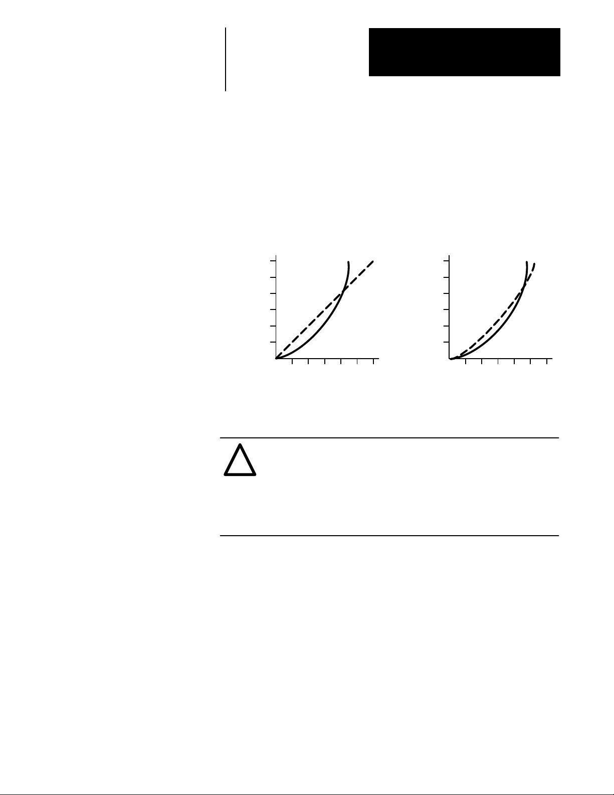
Shown below are typical variable torque curves plotting torque versus
speed. At slow speeds, if torque requirements continuously exceed levels
shown below (10 minutes or longer), a motor rated for the required speed
and torque range must be used. To guard against mechanical problems, it
is recommended that the entire drive train machinery be checked for
various limitations due to the range of the Bulletin 1336VT.
Typical Square and Cube Law Load Curves
Torque
and
HP
!
150
125
100
Square
Law
Loads
75
50
25
25 50 75 100 125 150
% Speed
TorqueHorsepower
Torque
150
125
100
and
HP
Cube
Law
Loads
75
50
25
25 50 75 100 125 150
% Speed
ATTENTION: Motors may overheat when operated at rated
torque for long periods of time below 50% base speed due to the
decreased air flow of armature driven fans.
Motors may require special balancing if operated at more than
125% of base speed. Refer to the motor manufacturer for proper
sizing of the motor for the intended application.
TorqueHorsepower
3-11
Page 28

Chapter
4
Specifications
Operating Environment Temperature: Open rating (heat sink), 0 to + 40°C.
Open rating (chassis components), 0 to +50°C.
Enclosed rating (heat sink), 0 to + 40°C.
Enclosed rating (chassis components), 0 to +50°C.
Relative Humidity: 5 to 95% non-condensing –– all ratings.
Altitude: 3,300 feet (1,000 meters) maximum without derating.
Vibration: 0.006 inches (0.152 mm) displacement, 1G peak.
Shock: 15G peak for 11ms duration (±1.0ms).
Storage Environment Temperature: – 40 to +85°C –– all ratings.
Relative Humidity: 5 to 95% non-condensing –– all ratings.
Enclosure Indicated by Catalog Number.
Open (IP00) –– all ratings.
NEMA Type 1 (IP20) –– all ratings.
4-1
Page 29

Chapter 4
Specifications
Input Power Conditioning General
Typically the 1336VT is suitable for direct connection to a correct voltage,
three phase, AC power line. There are however certain power line
conditions which may introduce the possibility of drive input power
component malfunction. To reduce the possibility of these malfunctions, a
line reactor or isolation type transformer may be required.
The basic rules for determining if a line reactor or isolation type
transformer is required are as follows:
1. If the AC line supplying the drive has power factor correction capacitors
connected, an AC line reactor or isolation type transformer must be
connected between the capacitor bank and the input to the drive.
2. If the AC line frequently experiences transient power interruptions or
significant voltage spikes, an AC line reactor or isolation type
transformer should be used.
Ungrounded Distribution Systems
All 1336VT drives are equipped with an MOV (metal oxide varistor) that
provides voltage surge protection and phase-to-phase plus phase-to-ground
protection which is designed to meet IEEE 587. The MOV circuit is
designed for surge suppression only (transient line protection), not
continuous operation.
With ungrounded distribution systems, the phase-to-ground connection of
the MOV could become a continuous current path to ground. MOV
line-to-line and line-to-ground voltages should not exceed the values listed
below. Exceeding these MOV ratings may cause physical damage to the
MOV.
Line-to-Line MOV Rating
Energy Rating = 320 Joules Turn On Voltage = 850-1000 volts
Line-to-Ground MOV Rating
Energy Rating = 380 Joules Turn On Voltage = 1500 volts
160 Joules
160 Joules
160 Joules
GND
220 Joules
4321
4-2
MOV1
Page 30

Chapter 4
Specifications
Input Power Voltage: 380-460V AC ±10%.
Frequency: 48 to 62Hz.
Phase: 3-phase.
AC Input Overvoltage Trip: 570V AC.
AC Input Undervoltage Trip: 275V AC.
Bus Overvoltage Trip: 810V DC
Bus Undervoltage Trip: 388V DC
Line Transient Protection: Line transients up to 5,000 volts peak, 320
Joules.
Logic Power Ride-Thru: 2 seconds or longer –– subject to the
integrity of user supplied external circuits.
Control Logic Noise: Showering arc transients from 350 to 2,000
Immunity volts peak.
Table
4.3 1336VT Input Current and kV
Rating kVA In kVA In kVA In Displacement
Amps In Code 380V AC 415V AC 460V AC Angle kW/kVA
5.6 003 3.7 4.0 4.5 0.95 0.85
7.5 005 4.9 5.4 6.0 0.95 0.85
11.4 007 7.5 8.2 9.1 0.95 0.85
14.6 010 9.6 10.5 11.6 0.95 0.85
22.0 015 14.5 15.8 17.5 0.95 0.85
28.0 020 18.4 20.1 22.3 0.95 0.90
35.0 025 23.0 25.2 27.9 0.95 0.90
44.0 030 29.0 31.6 35.1 0.95 0.90
54.0 040 35.5 38.8 43.0 0.95 0.90
67.0 050 44.1 48.2 53.4 0.95 0.90
78.0 060 51.3 56.1 62.1 0.95 0.90
97.0 075 63.8 69.7 77.3 0.95 0.90
124.0 100 81.6 89.1 98.8 0.95 0.90
154.0 125 101.4 110.7 122.7 0.95 0.90
178.0 150 117.2 127.9 141.8 0.95 0.90
235.0 200 154.7 168.9 187.2 0.95 0.90
296.0 250 194.8 212.8 235.8 0.95 0.90
A
Input Power
Factor
4-3
Page 31

Chapter 4
Specifications
Output Power Waveform: Sine coded pulse width modulated waveform.
Voltage: 0 to applied input voltage, 380V AC, 415V AC, or 460V
AC (maximum output voltage cannot exceed applied input
voltage).
Frequency Range: 0 to 250Hz with programmable minimum and maximum
limits.
Frequency Digital —
Resolution: Preset speeds (serial interface or pulse train input) to
0.005Hz of set frequency within the minimum and
maximum limits.
Analog —
Equal divisions between minimum and maximum limits to
the nearest 0.005Hz as a function of signal type.
Local speed pot (MOD-FA2 only), 1003 divisions.
Remote speed pot (TB2, Terminals 1, 2 and 3), 633
divisions.
0 to 10V DC input (TB2, Terminals 4 and 5), 976
divisions.
4 to 20mA input (TB2, Terminals 4 and 6), 726 divisions.
Frequency Digital Frequency Source: 0.0013% of set frequency,
Regulation: 0 to 40°C ambient temperature range.
Volts-per-Hertz: Fully programmable.
– Minimum 1 to 14.3V/Hz through local programming.
– Wider ranges available through optional programming.
4-4
Page 32

Output
Power (cont.)
Chapter 4
Specifications
Boost: 11 selectable values from 0 to 48V DC peak.
– Adjustable from 0 to 115V DC through optional
programming.
– Independent Accel/Run Boost to minimize motor
heating while maximixing motor torque.
Accel/Decel: Two independently programmable accel times.
Two independently programmable decel times.
Each time may be programmed over a range from
0 to 600 seconds.
Intermittent Programmable MOPC from 50 to 115% of rated output
Overload Capability: current for up to 1 minute maximum.
Inverse Time Designed to meet NEC and UL equivalent requirements.
Overload Capability: Adjustable timing from 50 to 115% of rated drive current
(Main Control Board Firmware Version 1.10 limited to 100%).
Drive 180% of rated output current.
Overcurrent Trip:
Ground Fault: Detects drive output ground fault path by sensing
unbalanced bus or input line currents.
Table
4.4 1336VT Output Current and kV
Drive kVA Out kVA Out kVA Out Dissipation Dissipation Dissipation CFM
Amps Out Rating 380V AC 415V AC 460V AC (BTU/hour) n (BTU/hour) n (BTU/hour) n Required n
5.0 B003 3.3 3.6 4.0 119 171 290 15
8.0 B005 5.3 5.8 6.4 154 222 375 20
11.0 B007 7.2 7.9 8.8 239 375 614 32
14.0 B010 9.2 10.1 11.2 290 460 750 40
21.0 B015 13.8 15.1 16.7 409 1040 1449 75
27.0 B020 17.8 19.4 21.5 477 1228 1705 88
34.0 B025 22.4 24.4 27.1 495 1449 1944 100
40.0 B030 26.3 28.8 31.9 597 1620 2217 115
52.0 B040 34.2 37.4 41.4 767 2404 3171 165
65.0 B050 42.8 46.7 51.8 1006 2882 3887 200
77.0 B060 50.7 55.3 61.3 1159 3001 4160 215
96.0 B075 63.2 69.0 76.5 1398 3274 4672 241
124.0 B100 81.6 89.1 98 .8 1773 5456 7229 375
156.0 B125 102.7 112.1 124.3 2114 8116 10230 527
180.0 B150 118.5 129.4 143.4 2387 8184 10571 545
240.0 B200 158.0 172.5 191.2 2933 12753 15686 810
300.0 B250 197.4 215.6 239.0 3171 14902 18073 932
A
Internal
Chassis
Component Heatsink
Heat Heat Total Minimum
n The above information is provided for reference only. For all ratings the user must verify that the selected enclosure will dissipate the total BTUs
generated within the enclosure without allowing the internal ambient to rise above 50°C. Enclosure mounting and location must allow for the heatsink
to extend outside the enclosure.
•When locating the drive allow a minimum clearance from other components of 4.0 inches (101.6 mm) on the top and bottom, 2.0 inches (50.8 mm) on
either side.
•When mounting the drive, ensure that the heatsink fins are vertical.
With the heatsink exposed to the ambient, the drive will dissipate heat as listed in the Output Current Table above.
4-5
Page 33

Chapter 4
Specifications
Required Control Inputs As a minimum requirement for drive operation, the following five control
inputs must be present to operate the drive:
Start
A momentary True input will start the drive. The drive will continue to run
until a stop input is issued or a drive fault occurs. A start input may come
from:
• The optional FA2, RP2 or RP3 control panel start pushbutton.
• A user supplied N.O. contact or start pushbutton connected to the
optional L1, L2, or L3 Logic Interface Board. Refer to Appendix A —
Logic Interface Options and the 1336-MOD-L1, L2, or L3 instruction
manual.
• A user supplied start signal sent to the optional G2 Remote I/O Interface
Board. Refer to the 1336-MOD-G2 instruction manual.
Stop
A momentary False input will stop the drive. A maintained True input will
permit the drive to run or jog. A stop input may come from:
• The optional FA2, RP2 or RP3 control panel stop pushbutton.
• A user supplied maintained contact or Stop pushbutton connected to the
optional L1, L2, or L3 Logic Interface Board. Refer to Appendix A —
Logic Interface Options and the 1336-MOD-L1, L2, or L3 instruction
manual.
• A user supplied stop signal sent to the optional G2 Remote I/O Interface
Board. Refer to the 1336-MOD-G2 instruction manual.
• The Main Control Board when Jumper J8 is installed between Pins 11
and 12. Refer to Chapter 6 — Wiring, page 6-16.
Enable
A maintained True input or a maintained closed contact will permit the
drive to start, run, or jog. A momentary False input or an open contact will
disable drive output. An enable input may come from:
• A user supplied maintained contact or switch connected to the optional
L1, L2 or L3 Logic Interface Board. Refer to Appendix A — Logic
Interface Options and the 1336-MOD-L1, L2 or L3 instruction manual.
4-6
• The Main Control Board when Jumper J9 is installed between Pins 7 and
8. Refer to Chapter 6 — Wiring, page 6-16.
Page 34

Required Control Inputs (cont.) Speed Reference
Speed reference sets the drive operating frequency. A speed reference input
may come from:
• A Control Panel speed potentiometer.
• A user supplied 10kΩ remote speed potentiometer connected to terminal
block TB2. Refer to Chapter 6 — Wiring.
• A 4-20mA analog signal connected to terminal block TB2. Refer to
Chapter 6 — Wiring.
• A 0-10V DC analog signal connected to terminal block TB2. Refer to
Chapter 6 — Wiring.
• A pulse train input signal connected to terminal block TB2. Refer to
Chapter 6 — Wiring.
• One of seven preset speed signals connected to the optional L1, L2, or
L3 Logic Interface Board, or the optional G2 Remote I/O Interface
Board. Refer to Appendix A — Logic Interface Options and the
1336-MOD-L1, L2 or L3 instruction manual or the 1336-MOD-G2
instruction manual.
Chapter 4
Specifications
Auxiliary
A maintained True input or a maintained closed contact will permit the
drive to start, run, or jog. A momentary False input or an open contact will
disable drive output and generate Fault F02. An auxiliary input may come
from:
• A user supplied maintained contact or switch connected to the optional
L1, L2 or L3 Logic Interface Board. Refer to Appendix A — Logic
Interface Options and the 1336-MOD-L1, L2, or L3 instruction manual.
• The Main Control Board when Jumper J9 is installed between Pins 9 and
10. Refer to Chapter 6 — Wiring, page 6-16.
4-7
Page 35

Chapter 4
Specifications
Optional Control Inputs Reverse
Reverse changes direction of motor rotation. Reverse inputs may come
from:
• A Control Panel direction pushbutton.
• The optional L1, L2 or L3 Logic Interface Board. Refer to Appendix A
— Logic Interface Options and the 1336-MOD-L1, L2 or L3 instruction
manual.
• The optional G2 Remote I/O Interface Board. Refer to the
1336-MOD-G2 instruction manual.
Jog
Jog jogs the drive at a pre-programmed jog speed. Jog inputs may come
from:
• A Control Panel jog pushbutton.
• The optional L1, L2 or L3 Logic Interface Board. Refer to Appendix A
— Logic Interface Options and the 1336-MOD-L1, L2 or L3 instruction
manual.
• The optional G2 Remote I/O Interface Board. Refer to the
1336-MOD-G2 instruction manual.
Speed Select
Speed select permits switching between two selected speed reference
sources. Speed select inputs may come from:
• The optional L1, L2 or L3 Logic Interface Board. Refer to Appendix A
— Logic Interface Options and the 1336-MOD-L1, L2 or L3 instruction
manual.
• The optional G2 Remote I/O Interface Board. Refer to the
1336-MOD-G2 instruction manual.
2nd Accel/Decel
4-8
2nd accel/decel permits switching between two internally programmed
nd
accel/decel rates. 2
accel/decel inputs may come from:
• The optional L1, L2 or L3 Logic Interface Board. Refer to Appendix A
— Logic Interface Options and the 1336-MOD-L1, L2 or L3 instruction
manual.
• The optional G2 Remote I/O Interface Board. Refer to the
1336-MOD-G2 instruction manual.
Page 36

Chapter 4
Specifications
Load Requirements A balanced 3-phase inductive motor load is typical. Other motor loads may
require application assistance.
Contact Outputs The following contact outputs are available as standard:
Run: 1 N.O. contact, closed when drive is running.
At Speed: 1 N.O. contact, closed when the drive is at command speed
(within 0.5% of maximum programmed speed), or the
drive reaches the set point reference frequency
programmed by Parameter 77.
Fault: 1 set of Form C contacts that change state on drive fault or
loss of power.
Drive Alarm: 1 set of Form C contacts that change state to indicate that
the drive is operating outside of rated limits and that a fault
is imminent.
Drive Alarm Conditions are:
• Drive output current is above 115% of rated current.
• Drive output current is above the MOPC limit set by
Parameter 36.
• Bus voltage is above 110% of nominal input voltage. A
continued rise in bus voltage may result in Parameter 11
Decel Frequency Hold affecting the decel ramp, or fault
F05 Bus Overvoltage.
• Bus voltage is below 85% of nominal input voltage.
• Precharge not complete.
• Parameter 14 Auto Restart is active.
Analog Outputs 0-5V DC output programmable to represent output frequency or percent of
drive load current.
Drive Displays Programming Display frequency and drive control source. May be
and Display toggled to program and display 60 drive parameters
Panels: –– 5-14, 16-50 and 72-86. Should a fault occur while the
drive is running, the panel will display the fault code.
Bus Charged: Internal neon display to indicate bus voltage is greater than
40V DC.
4-9
Page 37

Chapter 4
Specifications
Programmable Parameters The 1336VT drive logic uses a set of 90 user parameters to select and
control drive operation. Seventy-one of these parameters are accessible
through any of the Programming and Display Panels. All 90 are accessible
through the Serial Port.
4-10
Page 38

Installation
Chapter
5
General Installation Requirements
ATTENTION: An incorrectly applied or installed system can
result in component damage or reduction in product life. The most
!
common causes are:
• Wiring the AC line to drive output or control terminals.
• Improper bypass or output circuits not approved by
Allen-Bradley.
• Output circuits which do not connect directly to the motor.
• Incorrect or inadequate AC supply.
• Excessive ambient temperature.
Contact Allen-Bradley for assistance with application or wiring.
The 1336VT must be installed in an area where the following installation
and environmental guidelines are met.
• Cabinet mounting is upright, leaving room for a minimum clearance of 4
inches (102 mm) on the top and bottom and 2 inches (51 mm) on the
sides for proper ventilation.
• The drive is easily accessible for maintenance and troubleshooting.
• The rated altitude does not exceed 3,300 feet (1,000 meters).
• Vibration will be within the ratings outlined in Chapter 4 –
Specifications.
• The ambient atmosphere contains no volatile or corrosive gas, vapors or
dust.
• The relative humidity does not exceed 95% for all drive ratings.
• The ambient temperature for the drive heatsink is kept within 0 to +40°C
for all open ratings.
• The ambient temperature for the chassis components is kept within 0 to
+50°C.
Important: An input transformer should not be required for normal drive
operation. If the use of an input transformer is desired, only an isolation
type transformer should be used.
Before actual installation, remove all packing material, wedges or braces
from within and around the drive.
5-1
Page 39

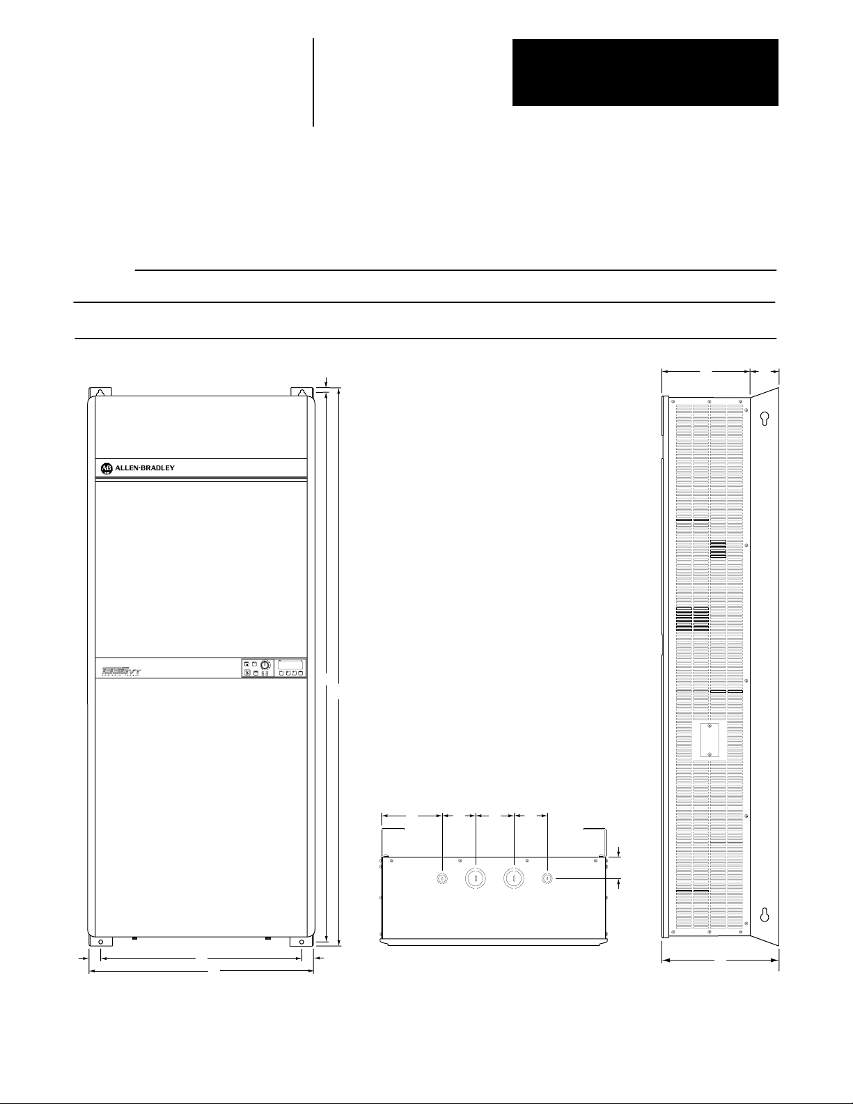
Chapter 5
Installation
Dimensions, Weights and Conduit Entry Locations
1336VT 521 Amp
Open Chassis (IP00) and NEMA Type 1 (IP20) Enclosures
Nominal Dimensions and Weights
in Inches (Millimeters) and Pounds (Kilograms)
A B C D E F G H I J K L M N Weight
Open
Chassis
NEMA
Type 1
11.13 18.75 8.76 8.38 18.15 1.38 0.30 6.26 2.50 — — — — — 31.3
(283) (477) (223) (213) (461) (35) (8) (159) (63.5) (14.2)
11.13 18.75 8.76 8.38 18.15 1.38 0.30 6.26 2.50 3.50 4.38 3.44 1.25 1.88 36.3
(283) (477) (223) (213) (461) (35) (8) (159) (63.5) (89) (111) (87) (32) (48) (16.5)
G
I H
E
B
P
R
Start
Stop
Freq
Jog
Enter
P
R
➋
➌
K
➍
J
➊
M
F
D
F
A
(NEMA Type 1 –– Front)
(NEMA Type 1 –– Bottom)
NLN
(NEMA Type 1 –– Side)
C
Mounting Holes –– 0.281" (7.13mm) Diameter
➊
➋
Conduit Entry –– 0.50" (13.0 mm) Diameter
➌
Conduit Entry –– 0.75" (19.0 mm) Diameter and 1.00" (25.4 mm) Diameter
➍
1336-MOD-S1 Serial Port Connector Cover Plate
5-2
Page 40

Dimensions, Weights and Conduit Entry Locations
1336VT 2734 Amp
Open Chassis (IP00) and NEMA Type 1 (IP20) Enclosures
Nominal Dimensions and Weights
in Inches (Millimeters) and Pounds (Kilograms)
A B C D E F G H I J K L M N Weight
Open
Chassis
NEMA
Type 1
11.13 22.66 8.76 8.38 22.06 1.38 0.30 6.26 2.50 — — — — — 37.1
(283) (576) (223) (213) (560) (35) (8) (159) (63.5) (16.8)
11.13 22.66 8.76 8.38 22.06 1.38 0.30 6.26 2.50 3.50 4.38 3.44 1.25 1.88 43.1
(283) (576) (223) (213) (560) (35) (8) (159) (63.5) (89) (111) (87) (32) (48) (19.5)
Chapter 5
Installation
G
I H
E
Start
Stop
Freq
Jog
Enter
P
R
B
P
R
➋
➌
K
➍
J
➊
F
(NEMA Type 1 –– Front)
➊
Mounting Holes –– 0.281" (7.13mm) Diameter
➋
Conduit Entry –– 0.50" (13.0 mm) Diameter
➌
Conduit Entry –– 0.75" (19.0 mm) Diameter and 1.00" (25.4 mm) Diameter
➍
1336-MOD-S1 Serial Port Connector Cover Plate
D
F
A
M
NLN
(NEMA Type 1 –– Bottom)
C
(NEMA Type 1 –– Side)
5-3
Page 41

Chapter 5
Installation
Dimensions, Weights and Conduit Entry Locations
1336VT 4052 Amp
Open Chassis (IP00) and NEMA Type 1 (IP20) Enclosures
Nominal Dimensions and Weights
in Inches (Millimeters) and Pounds (Kilograms)
A B C D E F G H I J K L M Weight
Open
Chassis
NEMA
Type 1
14.32 23.59 9.27 11.70 22.41 1.31 0.59 6.64 2.63 — — — — 47.3
(364) (599) (235) (297) (570) (33.3) (15) (159) (67) (21.5)
14.32 23.59 9.27 11.70 22.41 1.31 0.59 6.64 2.63 4.38 4.19 1.88 2.62 54.3
(364) (599) (235) (297) (570) (33.3) (15) (159) (67) (111) (106) (48) (7) (24.6)
G
I
H
E
B
Stop
Enter
P
R
P
R
Freq
Start
Jog
➋
➌
J
➍
➊
F
D
F
A
(NEMA Type 1 –– Front)
➊
Mounting Holes –– 0.312" (7.92mm) Diameter
➋
Conduit Entry –– 0.50" (13.0 mm) Diameter
➌
Conduit Entry –– 1.00" (25.4 mm) Diameter and 1.25" (32.0 mm) Diameter
➍
1336-MOD-S1 Serial Port Connector Cover Plate
5-4
K
M
L
(NEMA Type 1 –– Bottom)
M
C
(NEMA Type 1 –– Side)
Page 42

Dimensions, Weights and Conduit Entry Locations
1336VT 6577 Amp
Open Chassis (IP00) and NEMA Type 1 (IP20) Enclosures
Nominal Dimensions and Weights
in Inches (Millimeters) and Pounds (Kilograms)
A B C D E F G H I J K L M N O Weight
17.50 34.12 9.38 16.25 32.88 0.63 0.63 6.75 2.63 ——————85.0
Open
Chassis
NEMA
Type 1
(445) (867) (238) (413) (835) (16) (16) (172) (67) (38.3)
17.50 34.12 9.38 16.25 32.88 0.63 0.63 6.75 2.63 9.68 2.06 2.75 2.06 1.50 .63 90.0
(445) (867) (238) (413) (835) (16) (16) (172) (67) (246) (52) (70) (52) (38) (16) (40.5)
Chapter 5
Installation
G
H
I
E
P
R
Start
Stop
Freq
Jog
P
R
B
Enter
➍
J L
K
M
N
➊
F
D
A
(NEMA Type 1 –– Front)
➊
Mounting Holes –– 0.343" (8.71mm) Diameter
➋
Conduit Entry –– 0.50" (13.0 mm) Diameter and 0.75" (19.0 mm) Diameter
➌
Conduit Entry –– 1.00" (25.4 mm) Diameter and 1.50" (38.0 mm) Diameter
➍
1336-MOD-S1 Serial Port Connector Cover Plate
F
➋
➌
(NEMA Type 1 –– Top)
O
C
(NEMA Type 1 –– Side)
5-5
Page 43

Chapter 5
Installation
Dimensions, Weights and Conduit Entry Locations
1336VT 96180 Amp
Open Chassis (IP00) and NEMA Type 1 (IP20) Enclosures
Nominal Dimensions and Weights
in Inches (Millimeters) and Pounds (Kilograms)
A B C D E F G H I J K L M N Weight
Open
Chassis
NEMA
Type 1
25.16 47.94 13.80 23.88 46.82 0.64 0.62 10.55 3.25 — — — — — 200
(639) (1218) (351) (607) (1189) (16) (16) (268) (83) (91)
25.16 47.94 13.80 23.88 46.82 0.64 0.62 10.55 3.25 9.75 2.75 3.00 2.50 2.48 220
(639) (1218) (351) (607) (1189) (16) (16) (268) (83) (248) (70) (76) (64) (63) (100)
G
H
I
E
B
PR
Freq
Start
Jog
Stop
Enter
PR
M
L
J
K
➍
N
➊
F
D
A
(NEMA Type 1 –– Front)
➊
Mounting Holes –– 0.343" (8.71mm) Diameter
➋
Conduit Entry –– 0.875" (22.0 mm) Diameter and 1.125" (29.0 mm) Diameter
➌
Conduit Entry –– 1.375" (35.0 mm) Diameter and 1.968" (50.0 mm) Diameter
➍
1336-MOD-S1 Serial Port Connector Cover Plate
F
5-6
➋
➌
(NEMA Type 1 –– Top)
C
(NEMA Type 1 –– Side)
Page 44
Dimensions, Weights and Conduit Entry Locations
1336VT 240300 Amp
Open Chassis (IP00) and NEMA Type 1 (IP20) Enclosures
Nominal Dimensions and Weights
in Inches (Millimeters) and Pounds (Kilograms)
A B C D E F G1 G2 H I J K L M N Weight
25.16 62.94 17.50 23.92 61.82 0.62 0.62 0.50 11.75 5.75 — — — — — 380
Open
Chassis
NEMA
Type 1
(639) (1599) (445) (608) (1570) (16) (16) (13) (299) (146) (171)
25.16 62.94 17.50 23.92 61.82 0.62 0.62 0.50 11.75 5.75 4.06 6.75 7.75 3.88 3.12 450
(639) (1599) (445) (608) (1570) (16) (16) (13) (299) (146) (103) (171) (197) (99) (79) (203)
Chapter 5
Installation
G
PR
Freq
Start
Jog
Stop
Enter
PR
E
H
I
B
➍
➊
F
D
A
(NEMA Type 1 –– Front)
➊
Mounting Holes –– 0.343" (8.71mm) Diameter
➋
Conduit Entry –– 0.875" (22.0 mm) Diameter and 1.125" (29.0 mm) Diameter
➌
Conduit Entry –– 3.625" (92.0 mm) Diameter and 4.125" (105.0 mm) Diameter
➍
1336-MOD-S1 Serial Port Connector Cover Plate
F
J
K
➋
➌
(NEMA Type 1 –– Top)
M
L
N
C
(NEMA Type 1 –– Side)
5-7
Page 45

Wiring
Chapter
6
General Wiring Procedures
ATTENTION: Do not proceed without reading the information on this
page. Failure to understand procedures and hazards may result in personal
!
injury or equipment damage.
ATTENTION: An incorrectly applied or installed system can result in
component damage or reduction in product life. The most common causes
!
are:
W
iring the AC line to drive output or control terminals.
•
• Improper bypass or output circuits not approved by Allen-Bradley.
• Output circuits which do not connect directly to the motor.
• Incorrect or inadequate AC supply.
• Excessive ambient temperature.
Contact Allen-Bradley for assistance with application or wiring.
1. The National Electrical Code requires that a circuit breaker or fusible disconnect
switch be provided in the drive branch circuit. Providing drive input fusing
alone is not suf
this requirement. Selection of a branch circuit breaker or fusible disconnect
should be based on the drive input current rating. Refer to the Terminal Block
TB1 Wiring sections in this chapter for mandatory AC input fusing
recommendations for drive short circuit protection.
2. The National Electrical Code and local regulations govern the installation and
wiring of the 1336VT. All input and output power wiring, control wiring and
conduit must be brought through the drive conduit entry holes provided on the
enclosure. Connections to the drive must be made as shown in the following
sections and in accordance with the drive nameplate, National Electrical Code
requirements and any additional interconnection diagrams packed with the
drive.
3. The voltage on each phase of the incoming line to the drive must match the
drive input rating. Verify the drive rating by referring to the input voltage listed
on the drive nameplate. If the incoming line voltage is out of this tolerance,
equipment may be damaged or fail to operate.
4. If multiple drives are used, do not use common cabling for AC input or output
leads. If multiconductor cable is used, separate 3-conductor input and output
cable for each drive must be used.
ficient to meet NEC guidelines. The 1336VT does not provide
5. All signal wiring must be run separate from power or control wiring. Verify that
shielded cable and/or conduit is used if indicated on any interconnection
diagrams or in the following sections. If shielded cable is required, shields must
be grounded at the drive end only at one of the drive ground lugs provided.
Nearby relays, solenoids or brake coils can produce electrical noise transients
6.
and cause erratic drive behavior. T
across the coils of these devices.
7. Since most startup difficulties result from incorrect wiring, every precaution
should be taken to assure that the wiring is as indicated on the diagrams and
information packed with the drive.
ransient suppression networks must be added
6-1
Page 46

Chapter 6
Wiring
Input Power Conditioning Typically, the 1336VT is suitable for direct connection to a correct voltage,
three phase, AC power line. There are, however, certain power line
conditions which will greatly increase the possibility of drive input power
component malfunction. To reduce the possibility of these malfunctions, a
line reactor or isolation type transformer may be required.
The basic rules for determining if a line reactor or isolation type
transformer is required are as follows:
1. If the AC line supplying the drive has power factor correction capacitors
connected, an AC line reactor or isolation type transformer must be
connected between the capacitor bank and the input to the drive.
2. If the AC line frequently experiences transient power interruptions of
significant voltage spikes, an AC line reactor or isolation type
transformer should be used.
Ungrounded Distribution Systems
All 1336VT drives are equipped with an MOV (metal oxide varistor) that
provides voltage surge protection and phase-to-phase plus phase-to-ground
protection which is designed to meet IEEE 587. The MOV circuit is
designed for surge suppression only (transient line protection), not
continuous operation.
With ungrounded distribution systems, the phase-to-ground connection of
the MOV could become a continuous current path to ground. MOV
line-to-line and line-to-ground voltages should not exceed the values listed
below. Exceeding these MOV ratings may cause physical damage to the
MOV.
Line-to-Line MOV Rating
Energy Rating = 320 Joules Turn On Voltage = 850-1000 volts
Line-to-Ground MOV Rating
Energy Rating = 380 Joules Turn On Voltage = 1500 volts
160 Joules
160 Joules
160 Joules
GND
220 Joules
4321
6-2
MOV1
Page 47

Chapter 6
Wiring
Wire Group Numbers The following chart identifies general wire categories that will be
encountered when installing the 1336VT. Each category has an associated
wire group number that is used in the following sections to identify the
wire to be used. Application and signal examples along with the
recommended type of cable for each group is provided. A matrix providing
the recommended minimum spacing between different wire groups run in
the same tray or separate conduit is also provided.
Wire
Category
Power
Control
Signal
Wire
Group
1
2
3
4
5
6
Application
AC Power
(> 600 V AC)
AC Power
(to 600 V AC)
115VAC or 115V DC
Logic
115V AC
Power
24V AC or 24V DC
Logic
Analog Signals
DC Supplies
Digital
(Low Speed)
Digital
(High Speed)
Signal
Example
2.3 KV, 3∅
AC Lines
480V, 3∅
Relay Logic
PLC I/O
Power Supplies
Instruments
PLC I/O
5-24V DC
Supplies
Power Supplies
TTL Logic Level
Pulse Train
Input
Recommended minimum spacing between different wire
Recommended
Cable
Wire
Group
Per NEC
Local Codes
and
Application
Requirements
Per NEC
❶
Local Codes
and
Application
Requirements
Per NEC
Local Codes
and
Application
Requirements
Per NEC
Local Codes
and
Application
Requirements
Belden 8760
Belden 8770
Belden 9460
In
Tray
Between
Conduit
In
Tray
Between
Conduit
In
Tray
Between
Conduit
In
Tray
Between
Conduit
All signal wiring must be run in separate steel conduit.
Different wire groups must be run in separate conduit
All Dimensions in Inches and (Millimeters)
Power1Power2Control3Control4Signal5Signal
9.00
(228.6)
9.00
(228.6)
9.00
(228.6)
9.00
(228.6)
9.00
(228.6)
Between Conduit
9.00
(228.6)
Between Conduit
6.00
(152.4)
3.00 (76.2)
Between Conduit
6.00
(152.4)
3.00 (76.2)
Between Conduit
For Tray:
groups in the same tray
For Conduit:
9.00
(228.6)
3.00 (76.2)
6.00
(152.4)
3.00 (76.2)
9.00
(228.6)
6.00
(152.4)
9.00
(228.6)
6.00
(152.4)
6.00
(152.4)
9.00
(228.6)
6
A wire tray is not suitable.
Belden 8760
Belden 9460
The minimum spacing between conduit containing
different wire groups is 3.00 inches (78.2 mm).
Refer to precautions in General Wiring Procedures concerning multi-conductor cables.
❶
Belden 8760 — 18 AWG, twisted pair, shielded.
Belden 8770 — 18 AWG, 3 conductor, shielded.
Belden 9460 — 18 AWG, twisted pair, shielded.
Note 1 Steel conduit is recommended for all 1336VT power or control wiring and required for all 1336VT signal wiring. All input and output power wiring,
control wiring or conduit should be brought through the drive conduit entry holes provided. Use appropriate connectors to maintain the
environmental rating of the enclosure.
Note 2 Spacing between wire groups is the recommended minimum for parallel runs of 200 feet or less.
Note 3 All shields for shielded cable must be grounded at the drive end only –– Terminal 3 or 4 of TB2 –– The other end must be insulated and remain
floating. Shields for cables from one enclosure to another must be grounded only at the enclosure nearest the drive. If splicing of shielded cables is
required, the shield must remain continuous and insulated from ground.
Note 4 AC and DC circuits must be run in separate conduit or trays.
Note 5 A voltage drop in motor leads may adversely affect motor starting and running performance. Installation and application requirements may dictate
that larger wire sizes than indicated in the NEC guidelines be used.
6-3
Page 48

Chapter 6
Wiring
Terminal Block TB1 Power Wiring Input and output power connections are marked on terminal block TB1, a
ten position terminal block on the drive backpanel. For maintenance and
setup procedures, the drive may be operated without a motor connected.
Important:
1. The 1336VT does not provide input power short circuit fusing.
Specifications for the recommended fuse size and type to provide drive
input power protection against short circuits are provided on the
following pages. Branch circuit breakers or disconnect switches cannot
provide this level of protection for drive components.
2. Each Bulletin 1336VT must have its own dedicated input and output
power leads. If multiconductor cable is used, separate 3-conductor input
and output cable for each drive must be used.
3. For multimotor operation, the combined total of motor full load current
must not exceed the rated output current of the drive.
4. Verify that the motor windings are properly connected to receive the full
drive output voltage rating.
5. For 5-77 Amp drive ratings, two ground terminals have been provided at
TB1. Either one of these terminals must be connected to earth ground or
the ground of the building system.
For 96-300 Amp drive ratings, one ground terminal that will accept two
ground leads has been provided at TB1. Connect this terminal to earth
ground or the ground of the building system.
6-4
Page 49

Chapter 6
Wiring
ATTENTION:
1. Any disconnecting means wired to drive output terminals M1,
!
M2 and M3 must be capable of stopping the drive if opened
during drive operation. If opened during drive operation, the
drive will continue to produce output voltage into an open motor
circuit causing a potential shock hazard.
2. The start/stop control circuitry in the 1336VT includes
solid-state components. If hazards due to accidental contact with
moving machinery or unintentional flow of liquid, gas or solids
exist, an additional hard wired stop circuit is required to remove
AC line power to the drive. When AC input power is removed,
there will be a loss of inherent regenerative braking effect and
the motor will coast to a stop. An auxiliary braking method may
be required.
The 1336VT is intended to be controlled by control input signals
that will start and stop the motor. A device that routinely
disconnects then reapplies line power to the drive for the purpose
of starting and stopping the motor must not be used. After a
hard wired stop has been initiated, allow at least one minute
before reapplying input power to the drive. The allowable
number of hard wired start/stops are 3 cycles within a 5 minute
period. Wait 10 minutes before attempting the next 3 hard wired
stop cycle to allow the drive precharge resistors to cool.
Refer to codes and standards applicable to your particular system
for specific requirements and additional information.
6-5
Page 50

Chapter 6
Wiring
Terminal Block TB1 552Amp Power Wiring
GND GND +DC –DC M1 M2 M3 L1 L2 L3
Earth
Ground
USE 75°C COPPER WIRE ONLY WIRE RANGE 6–14 AWG
TIGHTENING TORQUE 20 INCH POUNDS
∅A
1336
Dynamic Brake
Motor
∅B ∅C
❶❶❶
❷
∅A
∅B ∅C
AC Incoming Line
❶ User supplied drive input fuses.
❷ Motor disconnecting means including branch circuit, short circuit, and ground fault protection.
GND
Chassis ground is used to connect the drive chassis to a common ground.
The motor frame must also be connected to the same common ground.
Either earth ground or the ground of the building system must be used.
Refer to the motor manufacturer’s guidelines for additional information.
+ DC, - DC
DC bus terminals are reserved for the 1336 dynamic brake option. Refer to
the 1336 dynamic brake option instructions for installation and connection
details.
6-6
M1, M2, M3
Connect the motor leads to these terminals.
M1, M2, M3
Connect the motor leads to these terminals.
L1, L2, L3
Input AC line Terminals L1, L2, L3 (∅A, ∅B, ∅C) are not phase
sensitive.
Nominal input voltage is 380/415/460V AC ±10%, 3∅, 50/60 Hz.
Branch disconnect and short circuit protection is not part of the standard
1336VT and must be supplied by the user. Drive input fuses are required to
provide component protection against malfunction of electronic circuits.
Page 51

Chapter 6
Wiring
Terminal Block TB1 552Amp Power Wiring (cont.)
Maximum Wire Size and Torque Requirements
Power Drive Maximum
Rating Output Wire Wire Maximum
Code Current Group
003 5 Amps 2 6 AWG 20 In-lbs
005 8 Amps 2 6 AWG 20 In-lbs
007 11 Amps 2 6 AWG 20 In-lbs
010 14 Amps 2 6 AWG 20 In-lbs
015 21 Amps 2 6 AWG 20 In-lbs
020 27 Amps 2 6 AWG 20 In-lbs
025 34 Amps 2 6 AWG 20 In-lbs
030 40 Amps 2 6 AWG 20 In-lbs
040 52 Amps 2 6 AWG 20 In-lbs
n
W
ire group number chart, page 6-3.
C 16 mm
2
.
c 2.26 N-m.
Use the following guidelines when selecting branch circuit protection.
5 Amp Drive Fuse Size 10A Fuse Type KTK-R, JJS or Equivalent
8 Amp Drive Fuse Size 15A Fuse Type KTK-R, JJS or Equivalent
11 Amp Drive Fuse Size 20A Fuse Type KTK-R, JJS or Equivalent
14 Amp Drive Fuse Size 25A Fuse Type A4J, JJS or Equivalent
21 Amp Drive Fuse Size - A Fuse Type A4J -30, JJS -35 or Equivalent
27 Amp Drive Fuse Size 45A Fuse Type A4J, JJS or Equivalent
34 Amp Drive Fuse Size 60A Fuse Type A4J, JJS or Equivalent
40 Amp Drive Fuse Size - A Fuse Type A4J -60, JJS -70 or Equivalent
52 Amp Drive Fuse Size 80A Fuse Type A4J, JJS or Equivalent
n Size C Torque c
6-7
Page 52

Chapter 6
Wiring
Terminal Block TB1 6577Amp Power Wiring
Transform
er
T1
460V
415V
380V
1336
Earth
Groun
d
GND
Dynamic
Brake
USE 75°C COPPER WIRE ONLY WIRE RANGE 2/0 – 6 AWG
+DC –DC M1 M2 M3 L1 L2 L3
Motor
∅
∅
A
TIGHTENING TORQUE 120 INCH POUNDS
∅
B
C
❶ User supplied drive input fuses.
❷ Motor disconnecting means including branch circuit,
short circuit, and ground fault protection.
AC Incoming Line
∅A ∅B ∅C
❷
❶❶❶
Earth
Groun
d
GND
GND
Chassis ground is used to connect the drive chassis to a common ground.
The motor frame must also be connected to the same common ground.
Either earth ground or the ground of the building system must be used.
Refer to the motor manufacturer’s guidelines for additional information.
+ DC, - DC
DC bus terminals are reserved for the 1336 dynamic brake option. Refer to
the 1336 dynamic brake option instructions for installation and connection
details.
M1, M2, M3
Connect the motor leads to these terminals.
L1, L2, L3
Input AC line Terminals L1, L2, L3 (∅A, ∅B, ∅C) are not phase
sensitive.
Nominal input voltage is 380/415/460V AC ±10%, 3∅, 50/60Hz.
Branch disconnect and short circuit protection is not part of the standard
1336VT and must be supplied by the user. Drive input fuses are required to
provide component protection against malfunction of electronic circuits.
6-8
Page 53

Terminal Block TB1 - Fan Transformer Wiring
Chapter 6
Wiring
6577Amp Power Wiring (cont.)
65-77 Amp drives are shipped from the factory with Fan Transformer T1
connected for 460V operation. Fan Transformer T1 has three leads marked
460V, 380V and 415V, each terminated by a keyed connector. For 380 or
415V drive operation, the Fan Transformer lead at L2 must be unplugged
and reconnected as shown on the previous page
Maximum Wire Size and Torque Requirements
Power Drive Maximum
Rating Output Wire Wire Maximum
Code Current Group
050 65 Amps 2 2/0 AWG 120 In-lbs
060 77 Amps 2 2/0 AWG 120 In-lbs
n
W
ire group number chart, page 6-3.
C 70 mm
2
.
n Size C
c 13.56 N-m.
Torque c
Use the following guidelines when selecting branch circuit protection.
65 Amp Drive Fuse Size 100A Fuse Type A4J, JJS or Equivalent
77 Amp Drive Fuse Size 110A Fuse Type A4J, JJS or Equivalent
6-9
Page 54

Chapter 6
Wiring
Terminal Block TB1 96156Amp Power Wiring
AC Incoming Line
∅A ∅B ∅C
1336
Dynamic
Brake
USE 75°C COPPER WIRE ONLY WIRE RANGE 2/0 – 6 AWG
+DC –DC M1 M2 M3 L1 L2 L3
TIGHTENING TORQUE 120 INCH POUNDS
Motor
∅
∅
A
∅
B
C
❷
❶❶ ❶
❶ User supplied drive input fuses.
❷ Motor disconnecting means including branch circuit, short circuit, and ground fault protection.
Earth
Groun
d
GND
GND
Chassis ground is used to connect the drive chassis to a common ground.
The motor frame must also be connected to the same common ground.
Either earth ground or the ground of the building system must be used.
Refer to the motor manufacturer’s guidelines for additional information.
+ DC, - DC
DC bus terminals are reserved for the 1336 dynamic brake option. Refer to
the 1336 dynamic brake option instructions for installation and connection
details.
M1, M2, M3
Connect the motor leads to these terminals.
L1, L2, L3
Input AC line Terminals L1, L2, L3 (∅A, ∅B, ∅C) are not phase
sensitive.
For drives rated B075, nominal input voltage is 380/415/460V AC ±10%,
3∅, 50/60 Hz.
Branch disconnect and short circuit protection is not part of the standard
1336VT and must be supplied by the user. Drive input fuses are required to
provide component protection against malfunction of electronic circuits.
6-10
Page 55

Chapter 6
Wiring
Terminal Block TB1 96156Amp Power Wiring
(cont.)
Fan Transformer Wiring
96-156 Amp drives are shipped from
Fan 1
TB4
1
the factory with Fan Transformer T1
connected for 460V operation. Fan
Transformer T1 has three tab
connections marked 460V, 380V and
415V. For 380 or 415V drive
operation, the Fan Transformer lead
TB1
L1
L2
L3
120V AC
2
380V AC
415V AC
460V AC
at transformer T1 must be
unplugged and reconnected.
Maximum Wire Size and Torque Requirements
Power Drive Maximum
Rating Output Wire Wire Maximum
Code Current Group
075 96 Amps 2 2/0 AWG 120 In-lbs
100 124 Amps 2 2/0 AWG 120 In-lbs
125 156 Amps 2 2/0 AWG 120 In-lbs
n
W
ire group number chart, page 6-3.
C 70 mm
2
.
n Size C
c 13.56 N-m.
Torque c
T1
Use the following guidelines when selecting branch circuit protection.
96 Amp Drive Fuse Size 150A Fuse Type AA4J, JJS or Equivalent
124 Amp Drive Fuse Size 200A Fuse Type A4J, JJS or Equivalent
156 Amp Drive Fuse Size 250A Fuse Type AA4J, JJS or Equivalent
6-11
Page 56

Chapter 6
Wiring
Terminal Block TB1 180Amp Power Wiring
AC Incoming Line
∅A ∅B ∅C
1336
Dynamic
Brake
USE 75°C COPPER WIRE ONLY WIRE RANGE 350 MCM – 6 AWG
+DC –DC M1 M2 M3 L1 L2 L3
TIGHTENING TORQUE 275 INCH POUNDS
Motor
∅
∅
A
∅
B
C
❷
❶❶❶
❶ User supplied drive input fuses.
❷ Motor disconnecting means including branch circuit, short circuit, and ground fault protection.
Earth
Groun
d
GND
GND
Chassis ground is used to connect the drive chassis to a common ground.
The motor frame must also be connected to the same common ground.
Either earth ground or the ground of the building system must be used.
Refer to the motor manufacturer’s guidelines for additional information.
+ DC, - DC
DC bus terminals are reserved for the 1336 dynamic brake option. Refer to
the 1336 dynamic brake option instructions for installation and connection
details.
M1, M2, M3
Connect the motor leads to these terminals.
L1, L2, L3
Input AC line Terminals L1, L2, L3 (∅A, ∅B, ∅C) are not phase
sensitive.
Nominal input voltage is 380/415/460V AC ±10%, 3∅, 50/60 Hz.
Branch disconnect and short circuit protection is not part of the standard
1336VT and must be supplied by the user. Drive input fuses are required to
provide component protection against malfunction of electronic circuits.
6-12
Page 57

Chapter 6
Wiring
Terminal Block TB1 180Amp Power Wiring (cont.)
Fan Transformer Wiring
180 Amp drives are shipped from
Fan 1
TB4
1
the factory with Fan Transformer T1
connected for 460V operation. Fan
Transformer T1 has three tab
connections marked 460V, 380V and
415V. For 380 or 415V drive
operation, the Fan Transformer lead
TB1
L1
L2
L3
120V AC
2
380V AC
415V AC
460V AC
at transformer T1 must be
unplugged and reconnected.
Maximum Wire Size and Torque Requirements
Power Drive Maximum
Rating Output Wire Wire Maximum
Code Current Group
150 180 Amps 2 350 MCM 275 In-lbs
n
W
ire group number chart, page 6-3.
C 185 mm
2
.
n Size C
c 31.08 N-m.
Torque c
T1
Use the following guidelines when selecting branch circuit protection.
180 Amp Drive Fuse Size 300A Fuse Type A4J, JJS or Equivalent
6-13
Page 58

Chapter 6
Wiring
Terminal Block TB1 240300Amp Power Wiring
1336
Dynamic
Brake
USE 755C COPPER WIRE ONLY
WIRE RANGE 350 MCM - 6 AWG
TIGHTENING TORQUE 275 INCH
POUNDS
+DC -DC
jA
AC Incoming Line
jB
jC
USE 755C COPPER WIRE ONLY
WIRE SIZE 2 (3) AWG
TIGHTENING TORQUE 275 INCH POUNDS
❷
Motor
jA
M1 M2 M3 L1 L2 L3
User supplied drive input fuses.
❶
jB
jC
USE 755C COPPER WIRE ONLY.
WIRE RANGE 500 MCM - 0 AWG
TIGHTENING TORQUE 375 INCH
POUNDS
❶❶ ❶
❷ Motor disconnecting means including branch circuit, short circuit, and ground fault protection.
Earth
Ground
GND
GND
Chassis ground is used to connect the drive chassis to a common ground.
The motor frame must also be connected to the same common ground.
Either earth ground or the ground of the building system must be used.
Refer to the motor manufacturer’s guidelines for additional information.
+ DC, - DC
DC bus terminals are reserved for the 1336 dynamic brake option. Refer to
the 1336 dynamic brake option instructions for installation and connection
details.
M1, M2, M3
Connect the motor leads to these terminals.
ATTENTION: A hazard of potential damage to drive output
power components exists if there is insufficient load inductance to
!
permit the drive short circuit protection function to be effective.
Sufficient load inductance is provided by one of the following:
• Option 1336-MOD-LR.
• Load reactors of 10mH connected to each motor lead.
• Motor leads with a minimum length of 40 feet (12.2 meters)
between the drive and the motor.
6-14
Page 59

Terminal Block TB1 - L1, L2, L3
Chapter 6
Wiring
240300Amp Power Wiring (cont.)
Input AC line Terminals L1, L2, L3 (∅A, ∅B, ∅C) are not ∅ sensitive.
Nominal input voltage is 380/415/460V AC ±10%, 3∅, 50/60 Hz.
Branch disconnect and short circuit protection is not part of the standard
1336VT and must be supplied by the user.
Maximum Wire Size and Torque Requirements
Power Drive Terminal Block Terminal Block Terminal Block Terminal Block
Rating Output Wire Maximum Maximum Maximum Maximum
Code Current Group
200 240 Amps 2 350 MCM 275 In-lbs 500 MCM 375 In-lbs
250 300 Amps 2 350 MCM 275 In-lbs 500 MCM 375 In-lbs
n
W
ire group number chart, page 6-3.
C 185 mm
2
.
n Wire Size C
c 31.08 N-m.
a 240 mm
2
.
Q 42.38 N-m.
+DC and –DC +DC and –DC M1-M3 M1-M3
Torque c
Wire Size a Torque Q
Use the following guidelines when selecting branch circuit protection.
240 Amp Drive Fuse Size 400A Fuse Type A4J, JJS or Equivalent
300 Amp Drive Fuse Size 500A Fuse Type A4J, JJS or Equivalent
6-15
Page 60

Chapter 6
Wiring
Terminal Block TB2 and TB3 - Terminal block TB2 is located at the bottom of the Main Control Board.
Control and Signal Wiring TB2 is an eighteen position terminal block with markings of 1 to 18.
Terminal block TB3 is a twelve position terminal block located on optional
interface boards L1, L2 or L3 directly above terminal block TB2. If either
L1, L2 or L3 is present, refer to Appendix A — Logic Interface Options
for wiring details.
CAUTION
HAZARDOUS VOLTAGE ON CAPACITORS
WHEN NEON LIGHT IS ON. REMOVE POWER
AND WAIT 60 SECONDS BEFORE SERVICING.
ATTENTION
TENSION DANGEREUSE AU NIVEAU DES
CONDENSATEURS QUAND LES NEONS SONT
ALLUMES. COUPER LE COURANT ET
ATTENDRE 60 SECONDES AVANT DE
COMMENCER L'ENTRETIEN.
VORSICHT
AN DEN KONDENSATOREN BESTEHT
HOCHSPANNUNGSGEFAHR, WENN DS NEON-
LICHT AUFLECUDHTET. STROM UNTER-
BRECHEN UND 60 SEK. WARTEN BEVOR
SERVICEARBEITEN DURCHGEFÜHRT WERDEN.
ATTENZIONE
TENSIONE PERICOLOSA SUI CONDENSATORI
QUANDO LA LUCE AL NEON È ACCESA.
TOGLIERE L'ALIMENTAZIONE ED ASPETTARE 60
¿¬|– [¥
SECONDI PRIMA DI PRESTARE MANUTENZIONE.
†[Ÿ Ÿº |]º] ¬Ÿ[ ¿|] Ÿº][, <|>/º ¥‡º
¬Ÿ[ ¿|]
~|[º ¥‡º Ÿº][ <|>/º ¿Ÿº¿|]
|]º] ¬Ÿ[ ¿|] Ÿº][, <|>/º ¥‡º<|>/º ¥‡º
PRECAUCION
AVOLTAJE PERLIGROSO EN LS CAPACITORES
CUANDO LA LUZ DE NEON ESTÉ ENCENDIO.
ANTES DE DAR SERVICIO.
CORTE LA ENERGIA Y ESPERE 60 DEGUNDOS
GND
GND
Bus Charge
Neon Indicator
CAUTION
HAZARDOUS VOLTAGE ON
CAPACITORS WHEN NEON
LIGHT IS ON. REMOVE POWER
AND WAIT 60 SEC. BEFORE
SERVICING.
BULLETIN 1336VT ADJUSTABLE FREQUENCY AC DRIVE
C1
➁
➀
SW1
C2
R
P
Freq
R
P
Jog
Start
Stop
Spare Jumper
Location
Enter
J9 –– Pins 7 and 8
Pins 9 and 10
18
17
L3
L2
L1
M3
M2
M1
–DC
+DC
2
1
9
8
7
6
5
4
3
16
15
14
13
12
11
10
TB2
J8 –– Pins 11 and 12
6-16
Page 61

Chapter 6
Wiring
Terminal Block TB2 The drive is capable of operating from an optional Local or Remote
Control and Signal Wiring Control Panel with minimum connections to terminal block TB2. When
required, external operator elements may be connected to provide
additional drive control. Additional drive control functions and status
outputs are also available for use at TB2 as detailed on the following pages.
To
Pulse
Input
ISOL
To
To
A/D
1
75kΩ
A/D
To
A/D
2
1.4kΩ
3
215Ω215Ω
100Ω
47.5kΩ
Fro
m
D/A
100Ω
CR1 CR2 CR3 CR3 CR4 CR4
At Fault (Not) Drive (Not)Run
Speed Fault Alarm Drive
+–
Alarm
Chassis
Ground
Signal
Common
Pot
Low
53.3kΩ
0–10V
49.9Ω
+–
4–20mA
+–
200Ω
Analog
Meter
Pulse
Source
+–
100Ω
+5V
DC
3.42kΩ
1 2 3 4 5 6 7 8 9 10 11 12 13 14 15 16 17 18
Shield
High
Pot
Pot
Wiper
External
Speed Pot
Maximum Recommended
Signal Wire Group ❶ Wire Size ❷ Torque ❸
Terminals 1, 2, 3 External Speed Potentiometer 5 14 AWG 7 In-Lbs
Terminals 3 and 4 Signal Common 5 14 AWG 7 In-Lbs
Terminals 5, Signal Common 0-10V DC 5 14 AWG 7 In-Lbs
Terminals 6, Signal Common 4-20mA 5 14 AWG 7 In-Lbs
Terminals 7 and 8 Pulse Train 6 14 AWG 7 In-Lbs
Terminals 9, Signal Common Meter Output 5 14 AWG 7 In-Lbs
Terminals 10 and 11 At Speed Contact 3 14 AWG 7 In-Lbs
Terminals 11 and 12 Run Contact 3 14 AWG 7 In-Lbs
Terminals 13, 14, 15 Fault Contacts 3 14 AWG 7 In-Lbs
Terminals 16, 17, 18 Drive Alarm Contacts 3 14 AWG 7 In-Lbs
❶ W
ire group number chart, page 6-3.
❷ 2.50 mm
2
.
❸ .79 N-m.
6-17
Page 62

Chapter 6
Wiring
Terminal Block TB2 - Important: Control functions affected by drive parameter programming
Control and Signal Wiring (cont.) and selection are indicated on the following pages. Refer to the 1336VT
Programming Manual to verify that the drive is programmed to meet your
requirements.
Terminal 1
Potentiometer High
Full CW or high side external potentiometer connection.
Terminal 2
Potentiometer Wiper
Wiper external potentiometer connection.
Terminal 3
Potentiometer Low
Full CCW or low side external potentiometer connection
These terminals are provided for connecting a remote 10kΩ potentiometer.
The potentiometer frequency control is the range between drive minimum
and maximum frequency settings.
For drives with Main Control Board Firmware Version 1.0. or 1.10, the
frequency resolution is the range divided by 514, but no less than 0.005Hz.
For drives with Main Control Board Firmware Version 1.11-3.01, the
frequency resolution is the range divided by 633, but no less than 0.005Hz.
Terminals 1, 2, 3
Open Circuit Detection
For drives with Main Control Board Firmware Version 1.01 or 1.11-3.01,
drive logic is capable of detecting an open circuit potentiometer input at
TB2, Terminal 3. Drive logic will detect an open circuit at the
potentiometer low input only if the potentiometer wiper remains connected
to Terminal 2 and pot high is connected to Terminal 1.
6-18
For drives with Main Control Board Firmware Version 1.01, drive logic is
not capable of detecting an open circuit at TB2, Terminal 3.
Terminals 3 and 4
Signal Common
These terminals are provided to terminate both minus and drive common
signals to TB2. Terminals 3 or 4 are also used to terminate any shields for
cables connected to TB2.
Page 63

Chapter 6
Wiring
Terminal Block TB2 Control and Signal Wiring (cont.)
ATTENTION: Signal common is internally connected to chassis
ground. User minus or user common connections to signal common
!
must be capable of accepting this. If earth ground or cable shields
are used as signal current paths, signals may be degraded.
Terminal 5 and Signal Common
0-10V DC Input
This terminal is provided to terminate a 0 to +10V DC speed reference
signal. Parameter 84 sets the 0-10V DC signal to be either directly or
inversely proportional. The minus signal is terminated at Terminals 3 or 4.
The input impedance from Terminal 5 to either 3 or 4 is approximately
100kΩ. The range of frequency control is between the minimum and
maximum drive frequency settings. The frequency resolution is the range
divided by 976 (but no less than 0.005Hz). Refer to the 1336VT
Programming Manual for details.
ATTENTION: Unexpected machine acceleration can cause injury
or death.
!
If Parameter 84 is enabled, a loss of the 0-10V DC reference signal
at drive terminal block TB2 will allow the drive to immediately
accelerate to the maximum frequency set by Parameter 19.
Ensure that all control connection integrity is maintained and
routinely inspected.
ATTENTION: Terminal 5 of TB2 is internally protected from
reverse polarity signals or input signals rising above 12V DC. If
!
reverse polarity or voltage levels are maintained above 12V DC,
signals may be degraded and component damage may result.
6-19
Page 64

Chapter 6
Wiring
Terminal Block TB2 - Terminal 6 and Signal Common
Control and Signal Wiring (cont.)
4-20 mA Input
This terminal is provided to terminate a +4 to 20mA DC speed reference
signal. Parameter 84 sets the 4-20mA signal to be either directly or
inversely proportional. The minus signal is terminated at Terminals 3 or 4.
The input impedance from Terminal 6 to either 3 or 4 is approximately
250Ω. The range of frequency control is between the minimum and
maximum drive frequency settings. The frequency resolution is the range
divided by 726 (but no less than 0.005Hz). Refer to the 1336VT
Programming Manual for additional details.
ATTENTION: Unexpected machine acceleration can cause injury
or death.
!
If Parameter 84 is enabled, a loss of the 4-20mA reference signal at
drive terminal block TB2 will allow the drive to immediately
accelerate to the maximum frequency set by Parameter 19.
Ensure that all control connection integrity is maintained and
routinely inspected.
ATTENTION: Terminal 6 of TB2 is internally protected from
reverse polarity signals and input signals rising above 24mA. If
!
reverse polarity or current levels are maintained above 24mA,
signals may be degraded resulting in damage to the drive or
connected equipment.
6-20
Page 65

Terminal Block TB2 - Terminals 7 and 8
Chapter 6
Wiring
Control and Signal Wiring (cont.)
Pulse Source Input
These terminals are optically isolated and are provided to terminate a pulse
train signal to the drive (Terminal 8+, Terminal 7–). When selected, the
drive output frequency will be the pulse rate at Terminal 8 divided by the
setting of Parameter 46, the Pulse Scale Factor. Refer to the 1336VT
Programming Manual for details.
Example:
Pulse Scale Factor = 64 (factory setting)
For the drive to generate a 60 Hz drive output, the pulse rate at Terminal 8
must be 60 x 64 or 3,840 pulse- per-second.
Maximum pulse input frequency =
250 (max freq) x 255 (max scale factor) = 63,750 pulse- per-second.
Pulse Source Requirements
• The drive minimum and maximum frequency setting will limit the
output frequency to these settings if the pulse train results in a frequency
outside that band.
• The pulse train must be an externally powered square wave, TTL logic
level signal.
• At the +5V DC or high state, the signal source must produce a voltage
from 4 to 5.5V DC capable of 16mA.
• At the 0 volts state the voltage must drop to 0.4V DC or less.
ATTENTION: If reverse polarity or voltage levels are maintained
above +12V DC, signals may be degraded and component damage
!
may result.
Terminals 9 and Signal Common
Analog Meter Output
This terminal provides a 0 to +5V DC signal that may be used with a user
supplied analog meter. The load impedance of the meter must be 500Ω or
higher. Parameter 25 sets the supply signal to be proportional to either
drive output frequency or percent of load current. The minus signal is
terminated at Terminals 3 or 4. The output is proportional to the signal
selected reaching +5V DC at the maximum frequency setting or 115% of
current.
Important: The displayed load current is an approximate value calculated
from drive internal feedback. Motor characteristics will affect the accuracy
of the load current indication.
6-21
Page 66

Chapter 6
Wiring
Terminal Block TB2 - Terminals 10 and 11
Control and Signal Wiring (cont.)
At Speed
These terminals allow an internal drive supplied at speed contact to be used
in external circuits. Parameter 77 allows the at speed contact to be
programmed to change state within ±0.5% of maximum speed for one of
two conditions –– When the drive reaches command speed or when the
drive reaches a programmed set point reference frequency. The contact is
isolated from logic and other drive circuitry.
Resistive rating: 120V AC or 30V DC, 5.0 amps
Inductive rating: 120V AC or 30V DC, 2.0 amps
Terminals 11 and 12
Run
These terminals allow an internal drive supplied run contact to be used in
external circuits. The N.O. contact closes when the drive is running and
opens when the drive is stopped and not generating any output to the
connected load. The contact is isolated from logic and other drive circuitry.
Resistive rating: 120V AC or 30V DC, 5.0 amps
Inductive rating: 120 V AC or 30V DC, 2.0 amps
6-22
Terminals 13, 14, 15
Fault
These terminals allow internal drive supplied fault contacts to be used in
external circuits. The contacts are shown in the de-energized (faulted) state.
When the drive is powered up and no fault is present, the contacts will
change state, 13 to 14 will open, 14 to 15 will close.
Both the N.C. and N.O. contacts will change state
(13 to 14 will close, 14 to 15 will open) when the drive has detected a Fault
or power is removed from the drive.
Resistive rating: 120V AC or 30V DC, 5.0 amps
Inductive rating: 120 V AC or 30V DC, 2.0 amps
Page 67

Terminal Block TB2 - Terminals 16, 17, 18
Chapter 6
Wiring
Control and Signal Wiring (cont.)
Drive Alarm
These terminals allow internal drive supplied alarm contacts to be used in
external circuits. The contacts are shown in the de-energized (alarm) state.
When the drive is powered up and no alarm is present, the contacts will
change state: 16 to 17 will open, 17 to 18 will close.
Both the N.C. and N.O. contacts will change state
(16 to 17 will close, 17 to 18 will open) when the drive has detected an
alarm or power is removed from the drive.
Resistive rating: 120V AC or 30V DC, 5.0 amps
Inductive rating: 120 V AC or 30V DC, 2.0 amps
Drive Alarm Conditions are:
• Drive output current is above 115% of rated current.
• Drive output current is above the MOPC limit set by Parameter 36.
• Bus voltage is above 110% of nominal input voltage. A continued rise in
bus voltage may result in Parameter 11 Decel Frequency Hold affecting
the decel ramp, or fault F05 Bus Overvoltage.
• Bus voltage is below 85% of nominal input voltage.
• Precharge not complete.
• Parameter 14 Auto Restart is active.
6-23
Page 68

Operation
Chapter
7
Freq
Start
Stop
Important: 1336VT Control Panels are not intended to replace or be
considered a suitable alternative for an operator control station for all
applications. If two-wire control is installed, option L1, L2 or L3 must also
be installed. With two-wire control, the stop pushbutton on all Control
Panels will allow the drive to restart once the button is released. Refer to
codes and standards applicable to your particular system for specific
requirements and additional information.
Jog
P
R
Control Panel Programming and Display Panel
P
Enter
R
Drive Restart
Important: The 1336VT drive may be programmed to avoid responding to
unintentional start commands. The stop input to the drive must first be
false, then returned to true to restart the drive:
• When exiting programming at the Programming and Display Panel.
• After a power-on reset fault has occurred, if Parameter 14 is set to 0.
– F01 power-on reset is displayed when power is first applied to the
drive and when a fault is cleared.
– If Parameter 14 is set to 1 and Option L1, L2 or L3 is installed to
provide two-wire control, cycling a stop input is not required after
reapplying power or clearing a fault.
7-1
Page 69

Chapter 7
Operation
If this sequence is not followed, the drive will fault and display F11.
When Parameter 14 is set to 0, the stop command must be repeated twice,
once to clear the fault, then again to reset drive logic once the fault has
been cleared.
A stop input is any valid stop signal that the drive receives. Valid stop
inputs are:
• The Stop pushbutton on a Control Panel –– As shown on the following
page.
• The stop input wired to TB3 at Terminal 20 –– As explained in
Appendix A, Logic Interface Options.
• When serial communications is used, writing to Parameter 51 to clear
the fault, then setting the stop bit of the serial input control word in
Parameter 57 –– As explained in the 1336VT Programming Manual.
Local or Remote Control Panel
Start
Stop
!
Jog
ATTENTION: Unexpected machine motion can cause injury or
death. Do not use a Local or Remote Control Panel with option L1,
L2, or L3 in any 2-wire start/stop control application.
A maintained start command or 2-wire control between terminals
19 and 20 of TB3 on option L1, L2 or L3 will affect Control Panel
stop pushbutton operation. The drive will automatically restart after
the Control Panel stop pushbutton is depressed and released.
7-2
Page 70

Chapter 7
Operation
Local or Remote Control Panel To allow Control Panel control:
(cont.) • The Start pushbutton requires that Parameter 21 be set to on 1.
• The Jog pushbutton requires that Parameter 23 be set to on 1.
• The direction pushbutton requires that Parameter 22 be set to on 1.
• The speed potentiometer is dependent upon the programming of
Parameters 5 and 6 and the status of speed select. Speed select is
controlled by TB3, Terminal 27 or serial programming. Refer to Chapter
8 — Speed Selection for additional details.
Start
Stop
Jog
Pressing the Start pushbutton will initiate drive operation and accelerate the
drive to the selected speed if:
Parameter 21 is set to on 1.
The Stop pushbutton remains operational when stop devices are connected
to Control and Signal Wiring Terminal Block TB2, unless Option L1, L2 or
L3 is installed, and two-wired control has also been installed. Pressing the
stop pushbutton will initiate the stop sequence and the drive will cause the
motor to:
• Coast-to-stop if Parameter 10 is set to 0.
• Brake-to-stop by DC injection if Parameter 10 is set to 1.
• Ramp-to-stop if Parameter 10 is set to 2.
If the drive has stopped due to a fault, pressing the Stop pushbutton will
only clear the display and reset the drive, not correct the fault.
Pressing the Jog pushbutton will jog the drive if:
Parameter 23 is set to (on) 1 .
Pressing the direction pushbutton will cause the motor to ramp down to
zero, then ramp up to set speed in the opposite direction if:
Parameter 22 is set to (on) 1.
When power is applied to the drive, one of these two lights will be lit to
indicate the selected direction of motor rotation.
Turning the speed potentiometer will adjust or set drive output frequency if
the speed pot has been selected and is functional.
7-3
Page 71

Chapter 7
Operation
Programming and Display Panel
Freq
P
P
R
R
Enter
All Programming and Display Panels provide a means of displaying
different drive status conditions while providing pushbutton control for
selected viewing and parameter programming.
The Freq display is a three character display that shows:
Standby Status Display The standby status of the drive when it is waiting for a drive start or jog
command.
Freq
P
R
Output Frequency Display The drive output frequency appears when the drive is running.
Freq
P
R
Fault Display Fault codes appear if the drive detects a fault condition.
Freq
P
R
7-4
Page 72

Chapter 7
Operation
Parameter Programming Display Parameter values appear when viewing or programming drive parameters.
Freq
P
R
Operating Display The Pr display is a two character display that shows the frequency source
when the drive is in Standby, Jog or Running.
Freq
– 0 Control Panel speed pot – 5 TB2 speed pot input
– 1 0 to +10V input – 6 Jog selected
– 2 4-20mA input – 7 Preset Speed 1
– 3 Pulse train input – 8 Preset Speed 2
– 4 Serial input – 9 Preset Speed 3 or if Parameter 72 is
P
R
set to 1, Preset Speeds 4-7
Important: No dash indicates a parameter number rather than a frequency
source.
Parameter Viewing Display The parameter number appears when viewing parameters.
Freq
P
R
7-5
Page 73

Chapter 7
Operation
Parameter Programming A decimal point appears if parameter programming has been selected and
is allowed. If the programming function is locked out, check switch SW1
on the Local Display and Programming Panel Card, option FA2. The
switch must be set to C1 to allow parameter programming.
Freq
P
R
Fault Display Two dashes appear if a fault has occurred.
Freq
P
R
Special Display Enable Loss All dashes appear if an enable loss has occurred.
Freq
P
R
7-6
Page 74

Chapter
8
Speed Selection
Speed Source Priority The 1336VT drive can receive speed or frequency commands from a
number of sources. These sources have been given various priorities so that
speed source selection may be defined and understood. The numbered
speed sources shown below are listed by priority and how they are
selected.
Priority 1 - Jog Speed Jog may be selected if the drive is not running. Jog is selected by a Local
or Remote Control Panel Jog pushbutton, Terminal 22 of TB3, or by serial
input programming from an Allen-Bradley PLC. All Programming and
Display Panels will display Pr = -6 when jog is selected.
Priority 2 - Preset Speed 17 Preset speeds are selected by combinations of inputs at Terminals 24 and
26 of TB3 or by serial input programming from an Allen-Bradley PLC.
Freq
All Programming and Display Panels will display:
Pr = - 7 when preset Speed 1 is selected.
Pr = - 8 when preset Speed 2 is selected.
Pr = - 9 when preset Speed 3 is selected or if Parameter 72 is set to 1,
preset Speed 4, 5, 6 or 7.
P
R
8-1
Page 75

Chapter 8
Speed Selection
Priority 3 - Speed Select Input Is The speed source programmed by Parameter 6 will be selected when the
True speed select input at Terminal 27 is true. Parameter 6 may be programmed
- Parameter 6 for one of the following six sources:
Freq
P
R
Pr = - 0 if Parameter 6 = 0, Control Panel speed potentiometer
Pr = - 1 if Parameter 6 = 1, 0-10V DC input.
Pr = - 2 if Parameter 6 = 2, 4-20mA input.
Pr = - 3 if Parameter 6 = 3, pulse train input.
Pr = - 4 if Parameter 6 = 4, serial input.
Pr = - 5 if Parameter 6 = 5, remote speed potentiometer input.
Priority 4 - Speed Select Input Is The speed source programmed by Parameter 5 will be selected when the
False speed select input at Terminal 27 is false. The speed source programmed
- Parameter 5 by Parameter 5 will be the default speed source, the lowest speed source
priority. Parameter 5 may be programmed for one of the following six
sources:
Freq
P
R
8-2
Pr = - 0 if Parameter 5 = 0, Control Panel speed potentiometer.
Pr = - 1 if Parameter 5 = 1, 0-10V DC input.
Pr = - 2 if Parameter 5 = 2, 4-20mA input.
Pr = - 3 if Parameter 5 = 3, pulse train input.
Pr = - 4 if Parameter 5 = 4, serial input.
Pr = - 5 if Parameter 5 = 5, remote speed potentiometer input.
Page 76

Chapter
9
Startup
The following startup procedure is written for users who have a Control
Panel and a Programming & Display Panel installed and who are not using
a 2-wire drive control scheme. For users without a Control Panel and a
Programming & Display Panel, respective external commands and signals
must be substituted to simulate their operation.
ATTENTION: Power must be applied to the drive with the cover
removed to perform certain startup procedures. Voltages on many
!
components are at incoming line potential or bus voltage. To avoid
electric shock hazard or damage to equipment, do not touch any
drive component other than those specified in the startup
procedure.
ATTENTION: Become familiar with the equipment and read
through the wiring, speed selection and adjustment sections before
!
attempting to perform the startup procedures. Adjustments may be
required to meet specific load characteristics or operator
preference.
Exercise extreme care when performing any task on the drive.
Failure to do so may result in electric shock or equipment damage.
As shown on page 6-16, a bus charge neon indicator at the top of
the 1336VT has been provided to provide visual indication that bus
voltage is present. Bus voltage may be verified by using a
voltmeter and measuring the voltage between +DC and –DC on
terminal block TB1. Do not attempt to service the drive until the
neon indicator has extinguished and the bus voltage has discharged
to zero volts.
Important:
1. Power must be applied to the drive when viewing or changing 1336VT
parameters. Previous programming may effect the drive status when
power is applied in Step 7.
2. If option L1, L2 or L3 is installed, remote start circuits may be
connected to TB3 on the Interface Board. Confirm that all circuits are in
a de-energized state before applying power.
3. If option L1, L2 or L3 is installed, user supplied voltages may exist at
TB3 on the interface board even when power is not applied to the drive.
4. If you cannot complete a procedure, refer to Chapter 10 — Fault Codes
immediately. Do not proceed. Determine the cause of the problem and
correct the problem first, then return to the startup procedure.
9-1
Page 77

Chapter 9
Startup
Initial Operation Step 1
- Motor Disconnected
Verify that AC line power at the disconnect device is within the rated value
of the drive. Drive nameplate and alternate voltage ratings are listed in
Chapter 2 — Drive and Option Identification.
Step 2
Remove and lock out all incoming power to the drive. Remove the drive
cover and disconnect motor leads from drive terminals M1, M2 and M3.
Step 3
If one of the following optional interface boards is installed:
1336-MOD-L1
1336-MOD-L2
1336-MOD-L3
• Verify that interface input connections to the board match the voltage
rating of the board.
• Verify that enable and auxiliary interlock inputs are provided.
Step 4
If option L1, L2 or L3 is not installed, verify that the three spare jumpers
provided with the drive are installed correctly at connectors J8 and J9.
Control Board connector J8 –– Pins 11 and 12 jumpered
Control Board connector J9 –– Pins 7 and 8 jumpered
Pins 9 and 10 jumpered
Step 5
Confirm that all other optional inputs are connected to their correct
terminals and are secure.
Step 6
Replace the drive cover and tighten all thumbscrews.
9-2
Page 78

Chapter 9
Startup
Initial Operation Important: The remaining steps in this start up procedure are based
- Motor Disconnected (cont.) on factory parameter settings. If the drive has been previously
commissioned, parameter settings may not be compatible with this start up
procedure. Drive status and fault conditions will be unpredictable when
power is first applied in Step 7.
To obtain the proper results, initially change all parameter values to their
factory settings. As you proceed through the steps, change each parameter
to the setting that you require.
Step 7
Turn the Control Panel speed pot fully counterclockwise. Apply power to
the drive.
The Programming and Display Panel should light and display F01, then
after 3 seconds – – – . If any fault code is displayed after 3 seconds, record
the fault and immediately remove power, then determine the fault source.
Freq
P
R
Freq
P
R
Step 8
Use the Programming and Display Panel to view each of the 71 drive
parameters. Verify that each parameter is the value you require. If
parameter values must be changed, refer to Chapter 1 — Local
Programming, in the 1336VT Programming Manual. After all parameters
have been checked, return to the operating display by simultaneously
pressing the ▲ and ▼ pushbuttons.
9-3
Page 79

Chapter 9
Startup
Initial Operation Step 9a
- Motor Disconnected (cont.)
The PR portion of the Programming and Display Panel will indicate the
speed source currently being used. Verify that the drive will accept the
required speed reference sources.
Freq
P
R
Are preset speeds to be used?
No – Go to Step 9b.
Yes – Select preset Speed 1. Select preset Speed 5.
Display must be - 7. Display must be - 9.
Select preset Speed 2. Select preset Speed 6.
Display must be - 8. Display must be - 9.
Select preset Speed 3. Select preset Speed 7.
Display must be - 9. Display must be - 9.
Select preset Speed 4.
Display must be - 9.
Open all preset speed inputs.
9-4
Page 80

Initial Operation Step 9b
Chapter 9
Startup
- Motor Disconnected (cont.)
Speed select allows switching between one of two speed references. Is the
speed select function being used?
No – Go to Step 9c.
Yes – Close the speed select input. The display will show the speed
source programmed in Parameter 6. Parameter 6 may be one of the
following values.
Freq
P
R
Pr = - 0 if Parameter 6 = 0, Control Panel speed potentiometer.
Pr = - 1 if Parameter 6 = 1, 0-10V DC input.
Pr = - 2 if Parameter 6 = 2, 4-20mA input.
Pr = - 3 if Parameter 6 = 3, pulse train input.
Pr = - 4 if Parameter 6 = 4, serial input.
Pr = - 5 if Parameter 6 = 5, remote speed potentiometer input.
Check Parameter 84 – Analog Inverse.
If set to 1 (On), the 0-10V DC or 4-20mA input signals at Terminal Block
TB2 in the drive will produce an inverse speed signal.
A 0V DC or 4mA signal will produce maximum drive output frequency as
set by Parameter 19. A 10V DC or 20mA signal will produce minimum
drive output frequency as set by Parameter 16.
9-5
Page 81

Chapter 9
Startup
Initial Operation Step 9c
- Motor Disconnected (cont.)
The default selection or the speed source selected with the speed select
open is the source programmed in Parameter 5. Parameter 5 may be one of
the following values:
Freq
P
R
Pr = - 0 if Parameter 5 = 0, Control Panel speed potentiometer
Pr = - 1 if Parameter 5 = 1, 0-10V DC input.
Pr = - 2 if Parameter 5 = 2, 4-20mA input.
Pr = - 3 if Parameter 5 = 3, pulse train input.
Pr = - 4 if Parameter 5 = 4, serial input.
Pr = - 5 if Parameter 5 = 5, remote speed potentiometer input.
Check Parameter 84 – Analog Inverse.
If set to 1 (On), the 0-10V DC or 4-20mA input signals at Terminal Block
TB2 in the drive will produce an inverse speed signal.
A 0V DC or 4mA signal will produce maximum drive output frequency as
set by Parameter 19. A 10V DC or 20mA signal will produce minimum
drive output frequency as set by Parameter 16.
Step 10
For convenience, the control elements on the Control Panel should be
active.
Verify or change the following parameters:
Set Parameter 5, Frequency Select = 0 (Control Panel speed pot active).
Set Parameter 21, Local Run = 1 (allow Control Panel run control).
For local reversing, set Parameter 22, Local Reverse = 1 (allow Control
Panel reverse control).
If jog is desired, set Parameter 23, Local Jog = 1 (allow Control Panel jog
control).
Return to the operating mode.
9-6
Page 82

Initial Operation Step 11
Chapter 9
Startup
- Motor Disconnected (cont.)
Stop
Start
With the Control Panel speed pot active (Pr display = - 0), turn the speed
pot fully counterclockwise.
Reset the drive by pressing the Stop pushbutton.
Press the Start pushbutton and start the drive.
The drive will ramp to the minimum speed set by Parameter 16.
Important: If a dwell frequency is programmed, the drive will first jump
to the dwell frequency for the dwell time, then ramp to the minimum
frequency value set by Parameter 16.
Step 12
While the drive is running, turn the local speed pot fully clockwise. The
drive will ramp to the maximum output frequency value set by Parameter
19.
Step 13
Press the direction pushbutton.
If reversing is active (Parameter 22 = 1), the drive will ramp to zero speed,
then ramp to maximum speed as indicated on the display panel. The LEDs
on the Control Panel will switch to the selected direction of rotation.
If reversing is not active (Parameter 22 = 0), pressing the direction
pushbutton will not change drive direction, and the same directional LED
on the Control Panel will remain lit.
9-7
Page 83

Chapter 9
Startup
Initial Operation Step 14
- Motor Disconnected (cont.)
Freq
While the drive is running, open the Enable Signal at TB3, Terminal 30.
The drive will stop and display the Enable Lost Code – – – - -.
Restore the enable signal.
Step 15Auxiliary Interlock Check
P
R
Start
Stop Stop
Jog
Restart the drive. With the drive running, open the auxiliary interlock
signal at TB3, Terminal 28. The drive will stop and display the Enable
Fault F02 – –.
Freq
P
R
Restore the auxiliary signal and reset the drive by pressing the Stop
pushbutton twice.
Step 16Jog Check
With the drive reset but not running, press and hold the Jog pushbutton on
the Control Panel.
If the Jog function is active (Parameter 23 = 1), the drive will start and
ramp to jog speed.
If the Jog function is not active (Parameter 23 = 0), the drive will not start.
9-8
Start
Step 17Skip Frequencies
Start the drive and slowly progress through the drive frequency range by
turning the Control Panel speed pot clockwise.
If skip frequencies are programmed, verify that the drive cannot be set to a
skip frequency but will remain above or below the skip frequency as set by
the Skip frequency range.
If skip frequencies are not programmed, verify that the drive will not skip
any frequencies in the drive operating range.
Page 84

Initial Operation Step 18Preset Frequencies
- Motor Disconnected (cont.)
If preset frequencies are not to be used, go to Step 19.
If Preset Frequencies 1-3 are used, set Parameter 72
(Activate Parameters 73-76) to 0 (Off). With the drive running, select each
of the preset frequencies by closing the inputs at Terminals 24 and 26 of
TB3. As each preset frequency is selected, the drive will ramp to that
frequency and remain there until the next frequency is selected.
If Preset Frequencies 4-7 are used, set Parameter 72
(Activate Parameters 73-76) to 1 (On) and repeat the procedure.
Step 19Accel and Decel Times
Estimate the time required for the motor to accelerate and decelerate
between Minimum Frequency (Parameter 16) and Maximum Frequency
(Parameter 19). With the drive running and controlled by the Control Panel
speed pot, check the accel time by turning the speed pot from fully
counterclockwise to fully clockwise.
Chapter 9
Startup
Stop
Check the decel time by turning the speed pot from fully clockwise to fully
counterclockwise.
If the second accel and decel times are to be used (Parameters 30 and 31),
repeat the above procedure using the second accel and decel times.
Step 20
Stop the drive and remove input power to the drive. When the local
displays are no longer lit, remove the drive cover and verify that the DC
bus neon indicator is not lit and that the bus voltage at terminals +DC and
-DC on the power terminal block is zero. Reconnect the motor leads to the
drive and replace the drive cover. Set the Control Panel speed pot fully
counterclockwise.
9-9
Page 85

Chapter 9
Startup
Initial Operation
- Motor Connected
SW1
ATTENTION: The following steps may cause motor rotation in
an unknown direction. To guard against equipment damage, always
!
disconnect the motor from the load before proceeding.
Step 21
Reapply power to the drive.
Minimize the possibility of incorrect motor rotation by changing the
following parameters.
If the chassis mounted Local Programming and Display Panel is installed,
C1
check that SW1 is in the C1 position to enable programming.
➁
➀
C2
Press Pr to enter the programming mode and change:
Parameter 16, minimum frequency, to 0
Parameter 43, dwell frequency, to 0.
Start
Simultaneously press ▲ and ▼ to return to the operating mode.
Step 22
Before starting the drive, select the forward direction of rotation and turn
the Control Panel speed pot fully counterclockwise.
Start the drive and slowly turn the speed pot until the motor begins to turn.
Check the direction of motor rotation, then stop the drive.
If the direction of rotation is correct, go to Step 23.
If the direction of motor rotation is incorrect:
• Remove input power, wait until the displays are no longer lit, then
remove the drive cover.
• Verify that the bus is fully discharged and that the bus voltage at
terminals +DC and -DC on the power terminal block is zero.
• Interchange any two of the three motor leads at TB1 – M1, M2 or M3.
• Replace the cover, reapply power to the drive, then repeat Step 22 for
correct motor rotation.
9-10
Page 86

Initial Operation Step 23
- Motor Connected (cont.)
Turn the Control Panel speed pot fully counterclockwise.
Chapter 9
Startup
Start
Stop
Start the drive.
Slowly increase motor speed and check for proper motor operation
throughout the speed range of the drive.
Step 24
With the drive operating at 1/4 speed or greater:
Stop the drive and verify that the stopping mode selected by Parameter 10
occurs.
Stop
P
Step 25
Stop the drive.
Press Pr to enter the programming mode and reset the parameters in Step
R
21 and any other parameters that were changed during the setup procedure.
Review each parameter description in the Programming Manual.
Determine the value required for the application and set the parameter.
Make a record of any “estimated” values.
Press ▲ and ▼ simultaneously to return to the operating mode.
9-11
Page 87

Chapter 9
Startup
Initial Operation Step 26
- Motor Connected (cont.)
If the drive is to receive control signals and data from a programmable
controller via the MOD-G2 Remote I/O communication option, the
programmable controller must be tested with the motor disconnected from
the load.
Prepare all drive control signal interfaces and Remote I/O option for
programmable controller operation. Refer to Remote I/O Instruction
Manual.
Reset appropriate drive control parameters 5-50 and 72-86. Particular
attention must be given to Parameter 22 – Local Reverse and Parameter 84
– Analog Inverse.
Apply power and test the program. Observe drive operation and correct all
communications, drive operation and equipment malfunction default
problems immediately.
After achieving proper operation, record all parameter values in the
Programming Manual.
Step 27
ATTENTION: To avoid hazards of electrical shock or injury
from moving equipment, product or process ingredients:
!
• Alert all personnel.
• Install all guards.
• Check operation of all safety devices.
• Be prepared to stop the motor immediately.
Disconnect and lock-out all power. Connect the motor to the load.
Before applying power, review the parameter descriptions in the
Programming Manual. Each parameter may have a significant effect on
fundamental drive and motor operation regardless of the control method
used.
9-12
Page 88

Initial Operation Step 27
- Motor Connected (cont.) (cont.)
Apply power. Prepare to operate the drive and motor under actual control
and load conditions. It is desirable to begin at low torque and speed.
Chapter 9
Startup
Start
Stop
P
Start the motor and run the machine or process to determine if parameter
settings are acceptable for the application.
Stop the motor.
Press Pr to enter the programming mode if changes in parameter values are
R
necessary. Refer to the Programming Manual each time a change is made
to a parameter. Record each setting and the corresponding drive, motor,
and machine behavior (or process deviation) for future reference.
Simultaneously press ▲ and ▼ to return to the operating mode.
After achieving satisfactory operation, record all final parameter values in
the Programming Manual.
SW1
Stop
Step 28
Stop the drive. Disconnect and lock-out all power.
If the chassis mounted Local Programming and Display Panel is installed,
C1
the programming ability may be disabled by setting SW1 to C2. This
➁
➀
concludes the initial startup procedure.
C2
9-13
Page 89

2Position Mode Display Area
Chapter
10
Fault Codes
Up to 37 fault codes may be displayed for the 1336VT. In each instance, a
Fault may be reset by cycling power to the drive, or if Parameter 39 is set
to 1, by pressing the Stop pushbutton. Resetting a Fault will not correct the
problem. Corrective action must be taken prior to resetting the fault.
Freq
The two character PR display is not used as part of the fault code display.
However, it may be used to indicate the loss of enable.
P
R
3Position Fault Code Display Area
Special Display - Enable Fault
Special Test - Input Reset
Freq
P
R
The three character Freq display is used to indicate the fault code acronym.
The fault acronym will be displayed until a drive reset is initiated.
Freq
P
R
The enable interlock is open. The enable interlock is:
Jumper 7-8 of J9 on the Main Control Board if interface option L1, L2, L3
is not installed.
Terminal 30 of TB3 if interface option L1, L2, L3 is installed.
Freq
P
R
This is not a fault but a code that is displayed each time the drive is
powered up or when a fault is cleared. It indicates that drive logic is being
reset to initial conditions.
10-1
Page 90

Chapter 10
Fault Codes
Auxiliary Fault
Power Loss
Freq
P
R
The auxiliary input interlock is open. The auxiliary interlock is:
Jumper 9-10 of J9 on the Main Control Board if interface option L1, L2,
L3 is not installed.
Terminal 28 of TB3 if interface option L1, L2 L3 is installed.
Freq
P
R
Bus Undervoltage
Bus Overvoltage
Occurs only if Parameter 40 is set to 0 and input power is interrupted for
0.2 seconds. Monitor the incoming AC line for low voltage or line power
interruption.
Freq
P
R
Occurs when the DC bus drops below 388V DC.
Monitor the incoming AC line for low voltage or line power interruptions.
Freq
P
R
Occurs when the DC bus rises above 810V DC.
May be caused by high line voltage or excessive regeneration from the
motor. Monitor the AC line for high line voltage or transient conditions. If
caused by motor regeneration, extended decel time or dynamic braking
may be required.
10-2
Page 91

Motor Stalled
Chapter 10
Fault Codes
Freq
P
R
Indicates that the drive has not been able to change output frequency for 4
seconds.
Conditions sensed are:
Excessive
Curr
ent
The motor is drawing excessive current (over 115%). The motor load is
excessive and will not allow the drive to accelerate to set speed. A longer
accel time or a reduced load may be required.
Bus
Voltage Rise
The bus voltage has risen to 110% of nominal bus voltage. This indicates a
regeneration condition that will not let the drive decelerate to a lower
frequency. A longer decel time or dynamic braking may be required.
Motor Overload
Over Temperature
Freq
P
R
The drive output current has exceeded the % of current set by Overload
Current Parameter 38 for some period of time. The time is dependent on
the level of current above the set value. The fastest time is 115% of
Parameter 38 for one minute. This indicates an excessive motor load that
must be reduced to the value programmed by Parameter 38.
Freq
P
R
Drive logic has detected an open temperature switch on the drive heatsink
indicating that drive heatsink temperature is above 100°C. Check for
blocked or dirty heatsink fins. Check that the ambient temperature has not
exceeded 40°C. For 14 Amp and larger units, check the operation of the
drive cooling fan.
10-3
Page 92

Chapter 10
Fault Codes
Open Potentiometer
Serial Error
Freq
P
R
An open potentiometer circuit has been detected. Check the external
potentiometer circuit at TB2, Terminals 1, 2 and 3 for an open circuit.
Freq
P
R
This Fault indicates a break in communications between the drive and the
1336-MOD-G2 Remote I/O Board. This fault is sensed only after the drive
is powered up and has sensed the presence of the Remote I/O Board by
establishing a communications link to the board.
Operator Error
Overcurrent
Freq
P
R
Logic has detected incompatible parameters.
Verify the drive reset sequence after exiting the programming mode when
using a Programming and Display Panel.
Check Parameter 14. If set to 0, the stop input must be cycled once to
generate code F01, then again after power-on-reset is complete to reset the
drive.
Verify that Parameters 10 and 42 are compatible with Parameter 41.
Parameter 10, Stop Select, and Parameter 42, Slip Compensation, must be
compatible with Parameter 41, Motor Type, as detailed in the 1336VT
Programming Manual.
Freq
P
R
10-4
The drive has exceeded 180% of its current rating. Check for a short circuit
at the drive output or excessive load conditions at the motor.
Page 93

Ground Fault
U VW Output Short
Chapter 10
Fault Codes
Freq
P
R
A current path to earth ground has been detected at one or more of the
drive output terminals. Check the motor and external wiring to the drive
output terminals for a grounded condition.
Freq
P
R
A short circuit has been detected between two or more of the drive output
terminals. Check the motor and external wiring to the drive output
terminals for a shorted condition.
V UW Output Short
W UV Output Short
Negative Phase Transistor Short
Freq
P
R
A short circuit has been detected between two or more of the drive output
terminals. Check the motor and external wiring to the drive output
terminals for a shorted condition.
Freq
P
R
A short circuit has been detected between two or more of the drive output
terminals. Check the motor and external wiring to the drive output
terminals for a shorted condition.
Freq
P
R
A shorted drive transistor has been detected. Check drive output transistors,
both upper and lower portions of each transistor, for a shorted condition.
10-5
Page 94

Chapter 10
Fault Codes
Positive Phase Transistor Short
Precharge Open
Freq
P
R
A shorted drive transistor has been detected. Check drive output transistors,
both upper and lower portions of each transistor, for a shorted condition.
Freq
P
R
An error has been detected in the precharge circuit that does not allow
precharge to occur. Check the precharge circuit.
Clear Jammed
PWM Check
Drive Reset
Freq
P
R
A fault has been detected originating from the Base Driver/Power Supply
Board. Check all wire and cable connections to the Base Driver/Power
Supply Board. Replace the Base Driver/Power Supply Board if required.
Freq
P
R
A fault has been detected originating from the Base Driver/Power Supply
Board. Check all wire and cable connections to the Base Driver/Power
Supply Board. Replace the Base Driver/Power Supply Board if required.
Freq
P
R
10-6
A fault has been detected originating from the Base Driver/Power Supply
Board. Check all wire and cable connections to the Base Driver/Power
Supply Board. Replace the Base Driver/Power Supply Board if required.
Page 95

Loop Overrun
Motor Mode
Chapter 10
Fault Codes
Freq
P
R
A fault has been detected originating from the Base Driver/Power Supply
Board. Check all wire and cable connections to the Base Driver/Power
Supply Board. Replace the Base Driver/Power Supply Board if required.
Freq
P
R
A fault has been detected originating from the Base Driver/Power Supply
Board. Check all wire and cable connections to the Base Driver/Power
Supply Board. Replace the Base Driver/Power Supply Board if required.
Overspeed
Power Mode
PWM Loss
Freq
P
R
A fault has been detected originating from the Base Driver/Power Supply
Board. Check all wire and cable connections to the Base Driver/Power
Supply Board. Replace the Base Driver/Power Supply Board if required.
Freq
P
R
A fault has been detected originating from the Base Driver/Power Supply
Board. Check all wire and cable connections to the Base Driver/Power
Supply Board. Replace the Base Driver/Power Supply Board if required.
Freq
P
R
A fault has been detected originating from the Base Driver/Power Supply
Board. Check all wire and cable connections to the Base Driver/Power
Supply Board. Replace the Base Driver/Power Supply Board if required.
10-7
Page 96

Chapter 10
Fault Codes
Slave Timeout
Hertz Error
Freq
P
R
A fault has been detected originating from the Base Driver/Power Supply
Board. Check all wire and cable connections to the Base Driver/Power
Supply Board. Replace the Base Driver/Power Supply Board if required.
Freq
P
R
The drive cannot find a valid frequency. Check the combinations of skip
frequencies to see if they completely overlap the minimum to maximum
frequency range. Check that Minimum Frequency, Parameter 16, is less
than Maximum Frequency, Parameter 19.
Hertz Select
Master Timeout
Freq
P
R
A fault has been detected originating from the Main Control Board. Check
all wire and cable connections to the Main Control Board. Replace the
Main Control Board if required.
Freq
P
R
A communication fault has been detected between the Main Control Board
and the Base Driver/Power Supply Board. Check the cable connections
between the boards. Replace the Main Control Board or Base Driver/Power
Supply Board if required.
10-8
Page 97

EEPROM Error
Retries Exceeded
Chapter 10
Fault Codes
Freq
P
R
A fault has been detected originating from the Main Control Board. Check
all wire and cable connections to the Main Control Board. Replace the
Main Control Board if required.
Freq
P
R
The number of drive restart attempts set by Parameter 85 has been
exceeded. The fault must be cleared and the drive manually reset by
cycling power to the drive.
Boost Error
Negative Slope
Freq
P
R
An attempt has been made to set Parameter 83 (Run Boost) to a value
greater than Parameter 48 (Start Boost).
Freq
P
R
Logic has detected a negative slope on the V/Hz curve.
Compare Parameters 18 and 50.
Parameter 18, Base Voltage, must be equal to or greater than Parameter 50,
Break Volts.
Compare Parameters 48 and 50
Parameter 50, Break Volts, must be equal to or greater than Parameter 48,
Start Boost.
10-9
Page 98

Chapter 10
Fault Codes
Diagnostic Current Limit
PJump Error
Freq
P
R
The drive has reached 115% of rated output current –– The drive’s
hardware current limit while Parameter 82 (Amp Limit Fault Enable) was
on.
Freq
P
R
An attempt has been made to enable both P-Jump and Slip Compensation.
Parameters 78-80 are used to program a custom drive output waveform
(a P-jump waveform) for specific applications. Parameter 78
(Traverse Period) will enable Parameters 79 and 80 if set to a value other
than 0.0.
Parameter 42 is used to program slip compensation. Slip compensation is
active whenever Parameter 42 is set to a value other than 0.0 and cannot be
used if a P-jump waveform has been programmed.
10-10
Page 99

Appendix
A
Logic Interface Options
1336MODL1 The Contact Closure Interface Board provides a means of interfacing
+5V DC TTL Logic Contact various signals and commands to the 1336VT drive by using contact
Closure Interface Board closures. The board is self-powered and does not require a separate user
power source. Plug in connectors on the Interface Board allow it to be
plugged directly into connectors on the Main Control Board. Two
mounting thumb screws secure the board in place.
ATTENTION: If the Contact Closure Interface Board is to
replace either the 1336-MOD-L2 or 1336-MOD-L3, external
!
circuits must be reconfigured to operate at the +5V DC logic
potentials supplied by the board. The application of either +24V
DC or 115V AC to the Contact Closure Interface Board will
damage both the Interface Board and the Main Control Board.
Operation
Each of the twelve terminals on the board are defined as being either a user
command input signal or interface common.
When an open circuit is present between a terminal and interface common,
a +5V DC potential will exist. This represents the not selected state or high
= False.
When a closed circuit is present between a terminal and interface common,
the input will go low to approximately zero volts or true. When the input
signal is pulled low to interface common, a sinking current of 15-20mA
will flow.
Requirements
Circuits used with the Contact Closure Interface Board must meet the
following criteria:
• Circuits must be capable of operating with low = True logic.
• In the low state, external circuits must be capable of a sinking current of
approximately 20mA to pull the terminal voltage to 0.4V DC or less.
• In the high state, external circuits must allow the terminal voltage to rise
to a voltage of 2.5-5V DC.
A-1
Page 100

Appendix A
Logic Interface Options
1336MODL1
+5V DC TTL Logic Contact
Closure Interface Board (cont.)
390Ω
100Ω
+5V DC
100Ω
4.7kΩ4.7kΩ
390Ω
+5V DC
390Ω
4.7kΩ4.7kΩ
+5V DC
100Ω
+5V DC+5V DC
100Ω
390Ω
+5V DC
100Ω
390Ω
+5V DC
+5V DC
100Ω
4.7kΩ4.7kΩ
390Ω
+5V DC
+5V DC
100Ω
390Ω
+5V DC
19 20 21 22 23 24 25 26 27 28 29 30
3-Wire Control TB3
Start Stop Jog
SW1
Select
Aux EnableRev SW2 Speed
19 20 21 22 23 24 25 26 27 28 29 30
100Ω
INTERFACE
COMMON
4.7kΩ4.7kΩ
390Ω
+5V DC
I
100Ω
390Ω
+5V DC
CHASSIS
GROUND
4.7kΩ
GND
+5V DC
EARTH
GROUND
2-Wire Control TB3
Start/Stop
Contact
Signal Wire Group ❶ Wire Size ❷ Torque ❸
Terminal 19, Interface Common Start 5 14 AWG 7 In-Lbs
Terminal 20, Interface Common Stop ❹ 5 14 AWG 7 In-Lbs
Terminals 21, 25, 29 Interface Common 5 14 AWG 7 In-Lbs
Terminal 22, Interface Common Jog 5 14 AWG 7 In-Lbs
Terminal 23, Interface Common Reverse 5 14 AWG 7 In-Lbs
Terminal 24, Interface Common SW1 5 14 AWG 7 In-Lbs
Terminal 26, Interface Common SW2 5 14 AWG 7 In-Lbs
Terminal 27, Interface Common Speed Select 5 14 AWG 7 In-Lbs
Terminal 28, Interface Common Auxiliary ❹ 5 14 AWG 7 In-Lbs
Terminal 30, Interface Common Enable ❹ 5 14 AWG 7 In-Lbs
W
ire group number chart, page 6-3.
❶
❷ 2.5mm
2
.
❸ .79N-m.
❹ This signal must be present to permit the drive to operate from any control source.
A-2
Maximum Recommended
 Loading...