

Page 1

Installation Instructions
Wiring and Grounding Guidelines for Pulse Width Modulated (PWM) AC Drives
Page 2
Important User Information
IMPORTANT
Read this document and the documents listed in the additional resources section about installation, configuration, and
operation of this equipment before you install, configure, operate, or maintain this product. Users are required to
familiarize themselves with installation and wiring instructions in addition to requirements of all applicable codes, laws,
and standards.
Activities including installation, adjustments, putting into service, use, assembly, disassembly, and maintenance are required
to be carried out by suitably trained personnel in accordance with applicable code of practice.
If this equipment is used in a manner not specified by the manufacturer, the protection provided by the equipment may be
impaired.
In no event will Rockwell Automation, Inc. be responsible or liable for indirect or consequential damages resulting from the
use or application of this equipment.
The examples and diagrams in this manual are included solely for illustrative purposes. Because of the many variables and
requirements associated with any particular installation, Rockwell Automation, Inc. cannot assume responsibility or
liability for actual use based on the examples and diagrams.
No patent liability is assumed by Rockwell Automation, Inc. with respect to use of information, circuits, equipment, or
software described in this manual.
Reproduction of the contents of this manual, in whole or in part, without written permission of Rockwell Automation,
Inc., is prohibited.
Throughout this manual, when necessary, we use notes to make you aware of safety considerations.
WARNING: Identifies information about practices or circumstances that can cause an explosion in a hazardous environment,
which may lead to personal injury or death, property damage, or economic loss.
ATTENTION: Identifies information about practices or circumstances that can lead to personal injury or death, property
damage, or economic loss. Attentions help you identify a hazard, avoid a hazard, and recognize the consequence.
Identifies information that is critical for successful application and understanding of the product.
Labels may also be on or inside the equipment to provide specific precautions.
SHOCK HAZARD: Labels may be on or inside the equipment, for example, a drive or motor, to alert people that dangerous
voltage may be present.
BURN HAZARD: Labels may be on or inside the equipment, for example, a drive or motor, to alert people that surfaces may
reach dangerous temperatures.
ARC FLASH HAZARD: Labels may be on or inside the equipment, for example, a motor control center, to alert people to
potential Arc Flash. Arc Flash will cause severe injury or death. Wear proper Personal Protective Equipment (PPE). Follow ALL
Regulatory requirements for safe work practices and for Personal Protective Equipment (PPE).
Allen-Bradley, Rockwell Software, PartnerNetwork, PowerFlex, and Rockwell Automation are trademarks of Rockwell Automation, Inc.
Trademarks not belonging to Rockwell Automation are property of their respective companies.
Page 3

Summary of Changes
The information below summarizes the changes to this manual since the last
release.
New and Updated Information
Top ic Pag e
Added PowerFlex 525, PowerFlex 753, and PowerFlex 755 drives to the motor cable length cross
referenc e table.
Added motor cable length restriction tables for PowerFlex 525 drives.
Table 23, 400V (frames A…E) 90
Table 24, 480V (frames A…E) 91
Table 25, 600V (frames A…E) 92
Updated motor cable length restriction tables for PowerFlex 700H drives.
Table 32, 600V (frames 9…13) 100
Table 33, 690V (frames 9…13) 100
Updated motor cable length restriction tables for PowerFlex 700S drives.
Table 44, 600V (frames 3…13) 107
Table 45, 690V (frames 5…13) 108
Added motor cable length restriction tables for PowerFlex 753 and 755 wall mount drives.
Table 46, 400V (frames 1 and 2) 109
Table 47, 480V (frames 1 and 2) 111
Table 48, 600V (frames 3…7) 114
Table 49, 690V (frames 6 and 7) 117
Added motor cable length restriction tables for PowerFlex 755 floor mount drives.
Table 50, 400V (frames 9 and 10) 118
Table 51, 480V (frames 9 and 10) 120
Table 52, 600V (frames 8…10) 121
Table 53, 690V (frames 8…10) 123
83
Rockwell Automation Publication DRIVES-IN001M-EN-P - March 2014 3
Page 4

Summary of Changes
Notes:
4 Rockwell Automation Publication DRIVES-IN001M-EN-P - March 2014
Page 5

Table of Contents
Preface
Wire/Cable Types
About This Publication. . . . . . . . . . . . . . . . . . . . . . . . . . . . . . . . . . . . . . . . . . . . . 9
Intended Audience. . . . . . . . . . . . . . . . . . . . . . . . . . . . . . . . . . . . . . . . . . . . . . . . . 9
Additional Resources . . . . . . . . . . . . . . . . . . . . . . . . . . . . . . . . . . . . . . . . . . . . . . . 9
Recommended Cable/Wire . . . . . . . . . . . . . . . . . . . . . . . . . . . . . . . . . . . . . . . 10
General Precautions . . . . . . . . . . . . . . . . . . . . . . . . . . . . . . . . . . . . . . . . . . . . . . 10
Chapter 1
General . . . . . . . . . . . . . . . . . . . . . . . . . . . . . . . . . . . . . . . . . . . . . . . . . . . . . . . . . 11
Material . . . . . . . . . . . . . . . . . . . . . . . . . . . . . . . . . . . . . . . . . . . . . . . . . . . . . 11
Exterior Cover . . . . . . . . . . . . . . . . . . . . . . . . . . . . . . . . . . . . . . . . . . . . . . . 11
Temperature Rating . . . . . . . . . . . . . . . . . . . . . . . . . . . . . . . . . . . . . . . . . . 12
Gauge . . . . . . . . . . . . . . . . . . . . . . . . . . . . . . . . . . . . . . . . . . . . . . . . . . . . . . . 13
Number of Conductors . . . . . . . . . . . . . . . . . . . . . . . . . . . . . . . . . . . . . . . 13
Insulation Thickness and Concentricity . . . . . . . . . . . . . . . . . . . . . . . . 14
Geometry. . . . . . . . . . . . . . . . . . . . . . . . . . . . . . . . . . . . . . . . . . . . . . . . . . . . 14
Unshielded Cable . . . . . . . . . . . . . . . . . . . . . . . . . . . . . . . . . . . . . . . . . . . . 15
Shielded Cable . . . . . . . . . . . . . . . . . . . . . . . . . . . . . . . . . . . . . . . . . . . . . . . 16
Armored Cable. . . . . . . . . . . . . . . . . . . . . . . . . . . . . . . . . . . . . . . . . . . . . . . 17
European Style Cable . . . . . . . . . . . . . . . . . . . . . . . . . . . . . . . . . . . . . . . . . 19
Input Power Cables . . . . . . . . . . . . . . . . . . . . . . . . . . . . . . . . . . . . . . . . . . . . . . 19
Motor Cables . . . . . . . . . . . . . . . . . . . . . . . . . . . . . . . . . . . . . . . . . . . . . . . . . . . . 20
Cable for Discrete Drive I/O. . . . . . . . . . . . . . . . . . . . . . . . . . . . . . . . . . . . . . 21
Analog Signal and Encoder Cable. . . . . . . . . . . . . . . . . . . . . . . . . . . . . . . . . . 21
Communication . . . . . . . . . . . . . . . . . . . . . . . . . . . . . . . . . . . . . . . . . . . . . . . . . 22
DeviceNet . . . . . . . . . . . . . . . . . . . . . . . . . . . . . . . . . . . . . . . . . . . . . . . . . . . 22
ControlNet. . . . . . . . . . . . . . . . . . . . . . . . . . . . . . . . . . . . . . . . . . . . . . . . . . 23
Ethernet . . . . . . . . . . . . . . . . . . . . . . . . . . . . . . . . . . . . . . . . . . . . . . . . . . . . . 23
Remote I/O and Data Highway Plus (DH+) . . . . . . . . . . . . . . . . . . . 24
Serial (RS-232 and RS-485) . . . . . . . . . . . . . . . . . . . . . . . . . . . . . . . . . . . 24
Power Distribution
Chapter 2
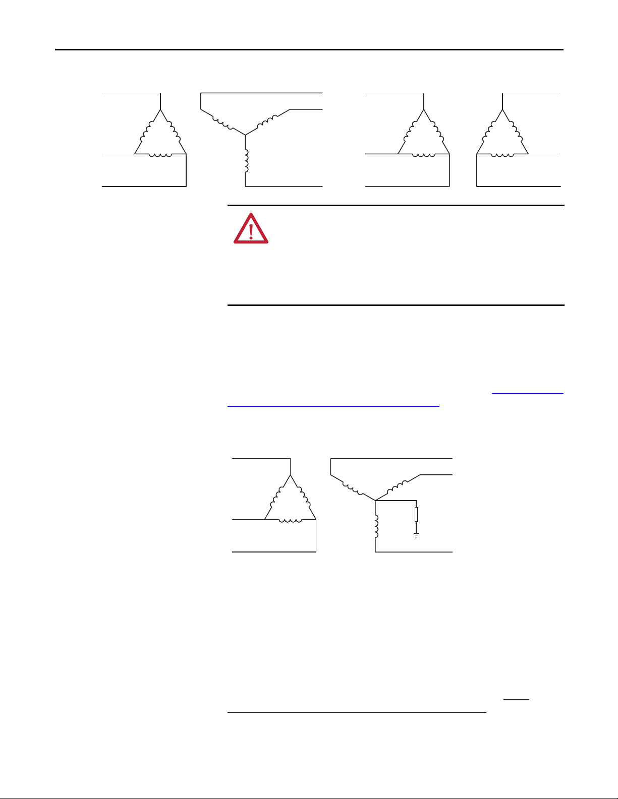
System Configurations . . . . . . . . . . . . . . . . . . . . . . . . . . . . . . . . . . . . . . . . . . . 25
Delta/Wye with Grounded Wye Neutral. . . . . . . . . . . . . . . . . . . . . . . 25
Delta/Delta with Grounded Leg,
or Four-wire Connected Secondary Delta . . . . . . . . . . . . . . . . . . . . . . 26
Three-phase Open Delta with Single-phase Center Tapped . . . . . . 26
Ungrounded Secondary. . . . . . . . . . . . . . . . . . . . . . . . . . . . . . . . . . . . . . . 27
High Resistance Ground . . . . . . . . . . . . . . . . . . . . . . . . . . . . . . . . . . . . . . 27
TN-S Five-wire System . . . . . . . . . . . . . . . . . . . . . . . . . . . . . . . . . . . . . . . 28
AC Line Voltage . . . . . . . . . . . . . . . . . . . . . . . . . . . . . . . . . . . . . . . . . . . . . . . . . 28
AC Line Impedance. . . . . . . . . . . . . . . . . . . . . . . . . . . . . . . . . . . . . . . . . . . . . . 28
Multi-drive Protection . . . . . . . . . . . . . . . . . . . . . . . . . . . . . . . . . . . . . . . 43
Surge Protection MOVs and Common Mode Capacitors. . . . . . . . . . . . 45
Use PowerFlex Drives with Regenerative Units . . . . . . . . . . . . . . . . . . . . . 46
Rockwell Automation Publication DRIVES-IN001M-EN-P - March 2014 5
Page 6

Table of Contents
Grounding
DC Bus Wiring Guidelines. . . . . . . . . . . . . . . . . . . . . . . . . . . . . . . . . . . . . . . . 46
Drive Lineup . . . . . . . . . . . . . . . . . . . . . . . . . . . . . . . . . . . . . . . . . . . . . . . . . 46
DC Bus Connections . . . . . . . . . . . . . . . . . . . . . . . . . . . . . . . . . . . . . . . . . 47
Chapter 3
Grounding Safety Grounds. . . . . . . . . . . . . . . . . . . . . . . . . . . . . . . . . . . . . . . . 49
Building Steel . . . . . . . . . . . . . . . . . . . . . . . . . . . . . . . . . . . . . . . . . . . . . . . . 49
Grounding PE or Ground . . . . . . . . . . . . . . . . . . . . . . . . . . . . . . . . . . . . . 50
RFI Filter Grounding . . . . . . . . . . . . . . . . . . . . . . . . . . . . . . . . . . . . . . . . . 50
Grounding Motors . . . . . . . . . . . . . . . . . . . . . . . . . . . . . . . . . . . . . . . . . . . 50
Grounding and TN-S Five-wire Systems . . . . . . . . . . . . . . . . . . . . . . . . 50
Noise Related Grounds . . . . . . . . . . . . . . . . . . . . . . . . . . . . . . . . . . . . . . . . . . . 51
Acceptable Grounding Practices . . . . . . . . . . . . . . . . . . . . . . . . . . . . . . . 53
Effective Grounding Practices . . . . . . . . . . . . . . . . . . . . . . . . . . . . . . . . . 54
Optimal – Recommended Grounding Practices . . . . . . . . . . . . . . . . . 54
Cable Shields. . . . . . . . . . . . . . . . . . . . . . . . . . . . . . . . . . . . . . . . . . . . . . . . . 55
Isolated Inputs . . . . . . . . . . . . . . . . . . . . . . . . . . . . . . . . . . . . . . . . . . . . . . . 55
Best Practices
Chapter 4
Mounting. . . . . . . . . . . . . . . . . . . . . . . . . . . . . . . . . . . . . . . . . . . . . . . . . . . . . . . . 57
Standard Installations . . . . . . . . . . . . . . . . . . . . . . . . . . . . . . . . . . . . . . . . . 57
EMC Specific Installations . . . . . . . . . . . . . . . . . . . . . . . . . . . . . . . . . . . . 58
Layout . . . . . . . . . . . . . . . . . . . . . . . . . . . . . . . . . . . . . . . . . . . . . . . . . . . . . . . 58
Hardware . . . . . . . . . . . . . . . . . . . . . . . . . . . . . . . . . . . . . . . . . . . . . . . . . . . . 59
Conduit Entry . . . . . . . . . . . . . . . . . . . . . . . . . . . . . . . . . . . . . . . . . . . . . . . . . . . 60
Entry Plates . . . . . . . . . . . . . . . . . . . . . . . . . . . . . . . . . . . . . . . . . . . . . . . . . . 60
Cable Connectors/Glands. . . . . . . . . . . . . . . . . . . . . . . . . . . . . . . . . . . . . 60
Shield Termination via Pigtail (lead) . . . . . . . . . . . . . . . . . . . . . . . . . . . 61
Ground Connections . . . . . . . . . . . . . . . . . . . . . . . . . . . . . . . . . . . . . . . . . . . . . 61
Wire Routing . . . . . . . . . . . . . . . . . . . . . . . . . . . . . . . . . . . . . . . . . . . . . . . . . . . . 63
General . . . . . . . . . . . . . . . . . . . . . . . . . . . . . . . . . . . . . . . . . . . . . . . . . . . . . . 63
Within A Cabinet . . . . . . . . . . . . . . . . . . . . . . . . . . . . . . . . . . . . . . . . . . . . 65
Within Conduit. . . . . . . . . . . . . . . . . . . . . . . . . . . . . . . . . . . . . . . . . . . . . . 66
Loops, Antennas, and Noise . . . . . . . . . . . . . . . . . . . . . . . . . . . . . . . . . . . 67
Conduit . . . . . . . . . . . . . . . . . . . . . . . . . . . . . . . . . . . . . . . . . . . . . . . . . . . . . . . . . 67
Cable Trays . . . . . . . . . . . . . . . . . . . . . . . . . . . . . . . . . . . . . . . . . . . . . . . . . . . . . . 68
Shield Termination. . . . . . . . . . . . . . . . . . . . . . . . . . . . . . . . . . . . . . . . . . . . . . . 69
Termination via Circular Clamp . . . . . . . . . . . . . . . . . . . . . . . . . . . . . . . 69
Shield Termination via Pigtail (lead) . . . . . . . . . . . . . . . . . . . . . . . . . . . 70
Shield Termination via Cable Clamp . . . . . . . . . . . . . . . . . . . . . . . . . . . 70
Conductor Termination . . . . . . . . . . . . . . . . . . . . . . . . . . . . . . . . . . . . . . . . . . 71
Power TB . . . . . . . . . . . . . . . . . . . . . . . . . . . . . . . . . . . . . . . . . . . . . . . . . . . . 71
Control TB . . . . . . . . . . . . . . . . . . . . . . . . . . . . . . . . . . . . . . . . . . . . . . . . . . 71
Signal TB . . . . . . . . . . . . . . . . . . . . . . . . . . . . . . . . . . . . . . . . . . . . . . . . . . . . 72
Moisture. . . . . . . . . . . . . . . . . . . . . . . . . . . . . . . . . . . . . . . . . . . . . . . . . . . . . . . . . 72
6 Rockwell Automation Publication DRIVES-IN001M-EN-P - March 2014
Page 7

Chapter 5
Table of Contents
Reflected Wave
Electromagnetic Interference
Motor Cable Length Restrictions
Tables
Glossary
Description. . . . . . . . . . . . . . . . . . . . . . . . . . . . . . . . . . . . . . . . . . . . . . . . . . . . . . 73
Effects On Wire Types . . . . . . . . . . . . . . . . . . . . . . . . . . . . . . . . . . . . . . . . . . . 73
Length Restrictions For Motor Protection . . . . . . . . . . . . . . . . . . . . . . . . . 74
Chapter 6
What Causes Common Mode Noise. . . . . . . . . . . . . . . . . . . . . . . . . . . . . . . 75
Containing Common Mode Noise With Cabling. . . . . . . . . . . . . . . . . . . 76
Conduit . . . . . . . . . . . . . . . . . . . . . . . . . . . . . . . . . . . . . . . . . . . . . . . . . . . . . 76
Shielded or Armored Power Cable . . . . . . . . . . . . . . . . . . . . . . . . . . . . . 76
How Electromechanical Switches Cause Transient Interference. . . . . . 77
How to Prevent or Mitigate Transient Interference from
Electromechanical Switches . . . . . . . . . . . . . . . . . . . . . . . . . . . . . . . . . . . . . . . 77
Enclosure Lighting . . . . . . . . . . . . . . . . . . . . . . . . . . . . . . . . . . . . . . . . . . . . . . . 80
Bearing Current . . . . . . . . . . . . . . . . . . . . . . . . . . . . . . . . . . . . . . . . . . . . . . . . . 80
Appendix A
Overview . . . . . . . . . . . . . . . . . . . . . . . . . . . . . . . . . . . . . . . . . . . . . . . . . . . . . . . . 81
Motor Cable Length Restrictions Tables Cross Reference. . . . . . . . 83
PowerFlex 4 Drives. . . . . . . . . . . . . . . . . . . . . . . . . . . . . . . . . . . . . . . . . . . . . . . 84
PowerFlex 4M Drives . . . . . . . . . . . . . . . . . . . . . . . . . . . . . . . . . . . . . . . . . . . . 85
PowerFlex 40 Drives . . . . . . . . . . . . . . . . . . . . . . . . . . . . . . . . . . . . . . . . . . . . . 86
PowerFlex 400 Drives . . . . . . . . . . . . . . . . . . . . . . . . . . . . . . . . . . . . . . . . . . . . 88
PowerFlex 525 Drives . . . . . . . . . . . . . . . . . . . . . . . . . . . . . . . . . . . . . . . . . . . . 90
PowerFlex 70 and 700 Drives . . . . . . . . . . . . . . . . . . . . . . . . . . . . . . . . . . . . . 93
PowerFlex 700H . . . . . . . . . . . . . . . . . . . . . . . . . . . . . . . . . . . . . . . . . . . . . . . . . 98
PowerFlex 700L. . . . . . . . . . . . . . . . . . . . . . . . . . . . . . . . . . . . . . . . . . . . . . . . . 100
PowerFlex 700S. . . . . . . . . . . . . . . . . . . . . . . . . . . . . . . . . . . . . . . . . . . . . . . . . 104
PowerFlex 753 and 755 Wall Mount Drives . . . . . . . . . . . . . . . . . . . . . . . 109
PowerFlex 755 Floor Mount Drives . . . . . . . . . . . . . . . . . . . . . . . . . . . . . . 118
1336 PLUS II and IMPACT Drives . . . . . . . . . . . . . . . . . . . . . . . . . . . . . . 124
1305 Drives . . . . . . . . . . . . . . . . . . . . . . . . . . . . . . . . . . . . . . . . . . . . . . . . . . . . 127
160 Drives. . . . . . . . . . . . . . . . . . . . . . . . . . . . . . . . . . . . . . . . . . . . . . . . . . . . . . 128
Reflected Wave Reduction Guidelines
(for catalog number 1321-RWR) . . . . . . . . . . . . . . . . . . . . . . . . . . . . . . . . . 129
. . . . . . . . . . . . . . . . . . . . . . . . . . . . . . . . . . . . . . . . . . . . . . . . . . . . . . . . . . . . . . . . 133
Index
. . . . . . . . . . . . . . . . . . . . . . . . . . . . . . . . . . . . . . . . . . . . . . . . . . . . . . . . . . . . . . . . 137
Rockwell Automation Publication DRIVES-IN001M-EN-P - March 2014 7
Page 8

Table of Contents
Notes:
8 Rockwell Automation Publication DRIVES-IN001M-EN-P - March 2014
Page 9

Preface
About This Publication
This manual provides the basic information needed to properly install, protect,
wire, and ground pulse width modulated (PWM) AC drives.
Intended Audience
This manual is intended for qualified personnel who plan and design installations
of PWM AC drives.
Additional Resources
These documents contain additional information concerning related products
from Rockwell Automation.
Resource Description
Safety Guidelines for the Ap plication, Installation and Maintenance of Solid State
Control, publication SGI-1.1
Don’t Ignore the Cost of Power Line Disturbance, publication 1321-TD001 Provides technical data on Allen-Bradley power conditioning products.
IEEE Guide for the Installation of Electrical Equipment to Minimize Electrical Noise
Inputs to Controllers from External Sources, publication IEEE 518.
Availa ble from IEEE Xplore Digital Librar y.
Recommended Practice for Powering and Grounding Electronic Equipment - IEEE
Emerald Book, publication IEEE STD 1100. Available from IEEE Xplore Digital Library
IEEE Recommended Practice for Grounding of Industrial and Commercial Power
Systems, publication IEEE Std 142-1991. Available from IEEE Xplore Digital Library
Cable Alternatives for PWM AC Drive Applications, publication IEEE Paper
No. PCIC-99-23. Available from IEEE Xplore Digital Library
EMI Emissions of Modern PWM AC Drives
IEEE Industry Applications Magazine
Electromagnetic Interference and Compatibility, Volume 3, by Donald R. J. White This book provides information EMI control methods and techniques.
Grounding, Bonding, and Shielding for Electronic Equipment and Facilities
(Military Handbook 419)
Noise Reduction Techniques in Electronic Systems by Henry W. Ott This book provides information on controlling emissions from electronic systems, and
Grounding for the Control of EMI by Hugh W. Denny This book provides grounding guidelines for the control of EMI.
EMC for Product Designers by Tim Williams This book provides the information needed to meet the requirements of the latest EMC
National Electrical Code (ANSI/NFPA 70)
Articles 250, 725-5, 725-15, 725-52 and 800-52 (www.nfpa.org)
Application Guide for AC Adjustable Speed Drive Systems,
NEMA (www.nema.org
IEC 60364-5-52 Selection and Erection of Electrical Equipment - Wiring systems, IEC
(www.iec.ch)
.
, Nov./Dec. 1999
).
Provides general guidelines for the application, installation, and maintenance of solid-state
control devices or assemblies.
Provides techniques for installing controllers and control systems so that proper operation
can be achieved in the presence of electrical noise.
Provides the recommended practices for powering and groundiing electronic equipment.
.
Provides recommended practices to ground power systems.
.
Describes an alternative solution for cables used with IGBT variable frequency drives (VFDs).
Provides an understanding of EMI issues and with pre-installation and post-installation
guidelines.
Provides grounding, bonding, and shielding applications for communication electronics
equipments and facilities.
techniques for providing electromagnetic compatibility (EMC).
directive.
Provides information on the installation of electrical components, signaling and
communication conductors and grounding.
Provides a NEMA applicatio n guide for AC drive systems.
IEC wiring systems.
You can view or download publications at
http:/www.rockwellautomation.com/literature/
. To order paper copies of
technical documentation, contact your local Allen-Bradley distributor or
Rockwell Automation sales representative.
Rockwell Automation Publication DRIVES-IN001M-EN-P - March 2014 9
Page 10
Preface
Recommended Cable/Wire
General Precautions
The recommended wire and cable referenced in this publication can be obtained
from third-party companies found in our PartnerNetwork™ Encompass Program.
For further information on these suppliers and their products, follow these steps
to find recommended wire and cable for your drives.
1. Go to the Encompass website at http://www.rockwellautomation.com/
rockwellautomation/sales-partners/complementary-products/
overview.page.
2. Under Find an Encompass Referenced Product, click FIND NOW.
3. In the Product Category pull-down list, choose Drive - Cables.
4. Click SEARCH.
ATT EN TI ON : To avoid an electric shock hazard, verify that the voltage on the
bus capacitors has discharged before performing any work on the drive.
Measure the DC bus voltage at the +DC and –DC terminals of the power
terminal block. The voltage must be zero.
10 Rockwell Automation Publication DRIVES-IN001M-EN-P - March 2014
Page 11

Chapter 1
Wire/Cable Types
AC drive installations have specific wire and cable requirements. This section
includes information about the major issues for proper selection of cable, and
provides recommendations to address these issues. Consider these conditions and
requirements when choosing cable material and construction for your
installation:
• Environment – such as moisture, temperature, and harsh or corrosive
chemicals.
• Mechanical needs – such as geometry, shielding, flexibility, and crush
resistance.
• Electrical characteristics – such as cable capacitance/charging current,
resistance/voltage drop, current rating, and insulation. Insulation can be
the most significant of these. Because drives can create voltages in excess of
line voltage, the industry standard cables that were used in the past are not
the best choice for variable speed drives. Drive installations benefit from
cable that is significantly different than cable used to wire contactors and
push buttons.
• Safety issues – such as electrical code requirements, grounding needs, and
others.
General
Choosing incorrect cabling can be costly and can adversely affect the
performance of your installation.
Material
Use only copper wire. The wire clamp-type terminals in Allen-Bradley drives are
made for use with copper wire. If you use aluminum wire, the connections can
loosen and cause premature equipment failure.
Wire gauge requirements and recommendations are based on 75 °C (167 °F)
rating. Do not reduce wire gauge when you use higher temperature wire.
Exterior Cover
Whether shielded or unshielded, the cable must meet all of the application
requirements. Consider insulation value and resistance to moisture,
contaminants, corrosive agents, and other invasive elements. Consult the cable
manufacturer and Figure 1 on page 12
for cable selection criteria.
Rockwell Automation Publication DRIVES-IN001M-EN-P - March 2014 11
Page 12

Chapter 1 Wire/Cable Types
XLPE
PVC
20 mil or > (1)
230V 400/460V
15 mil
> 15.2 m (50 ft)
< 15.2 m (50 ft)
575V
Selecting Wire to Withstand Reflected Wave Voltage for New and Existing Wire Installations in
Conduit or Cable Trays
Conductor
Environment
Conductor
Insulation
Insulation
Thicknes s
DRY
(per NEC Article 100)
WET
(per NEC Article 100)
XLPE (XHHW-2)
Insulation for
< 600V AC
System
No RWR or
Ter mi na to r
Required
OK for < 600V AC
System
No RWR or
Terminator Required
Reflected Wave
Reducer?
RWR or
Ter m in a to r
No RWR or
Ter m in a to r
RWR or
Ter mi na to r
No RWR or
Ter mi na to r
Reflected Wave
Reducer?
Cable
Length
Number of
Drives in Same
Conduit or Wire
Tra y
15 mil PVC
in Not
Recommended.
Use XLPE
or > 20 mil
15 mil PVC
is Not
Recommended.
Use XLPE
or > 20 mil
Multiple Drives
in Single Conduit
or Wire Tray
Single Drive,
Single Conduit or
Wire Tray
See NEC Guidelines (Article 310
Adjustment Factors) for Maximum
Conductor Derating and Maximum
Wires in Con duit or Tray
(1) The minimum wire size for PVC cable with 20 mil or greater insulation is 10 gauge.
IMPORTANT
Figure 1 - Wire Selection Flowchart
Temperature Rating
In general, follow these temperature ratings for installations:
• In surrounding air temperature of 50 °C (122 °F), use 90 °C (194 °F) wire
(required for UL)
• In surrounding air temperature of 40 °C (104 °F), use 75 °C (167 °F) wire
(required for UL)
Refer to the user manual of the drive for other restrictions.
The temperature rating of the wire affects the required gauge. Verify that your
installation meets all applicable national, state, and local codes.
12 Rockwell Automation Publication DRIVES-IN001M-EN-P - March 2014
Page 13
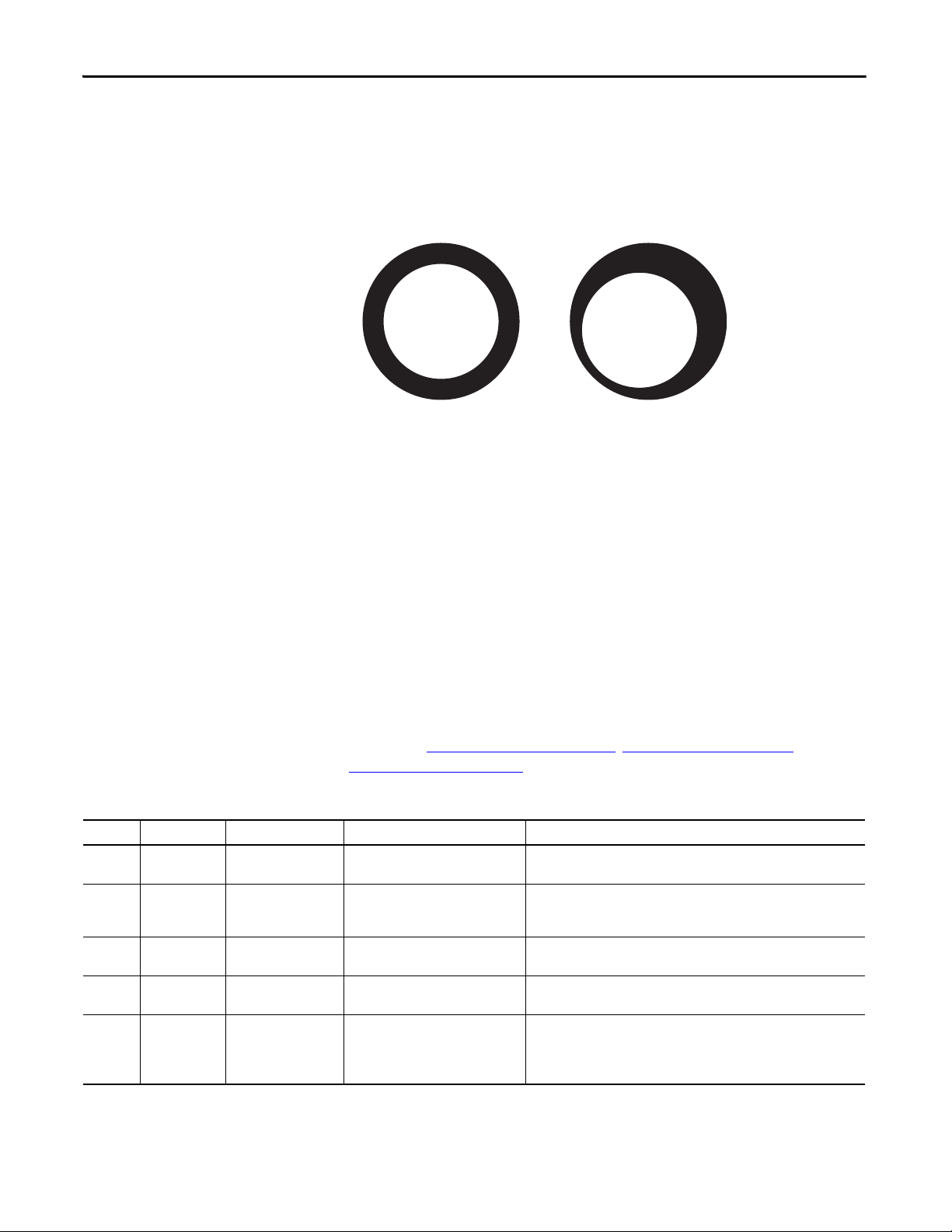
Wire/ Cable Typ es Chapter 1
One Ground Conductor
Three Ground Conductors
Gauge
The correct wire size is determined by a number of factors. The user manual for
each drive lists a minimum and maximum wire gauge based on the amperage
rating of the drive and the physical limitations of the terminal blocks. Local or
national electrical codes also set the required minimum gauge based on motor
full load current (FLA). Follow both of these requirements.
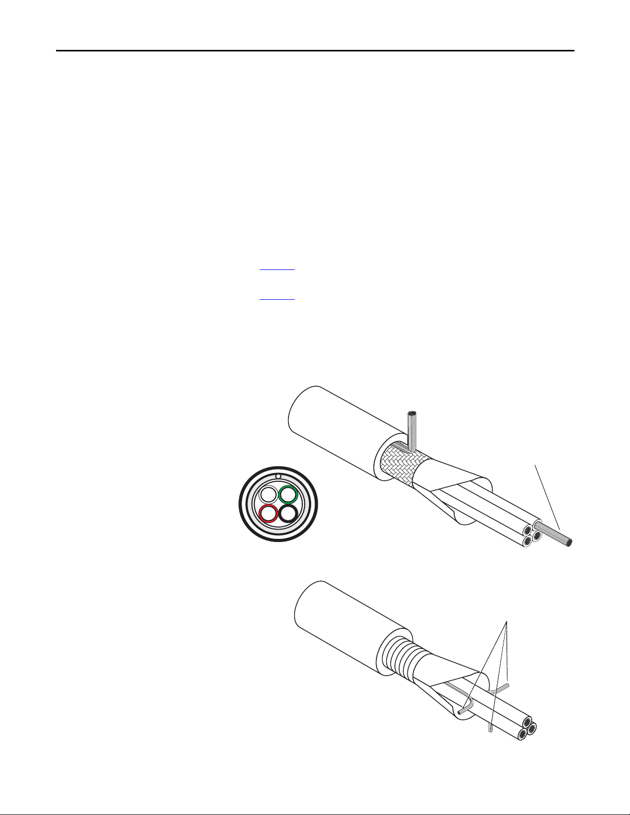
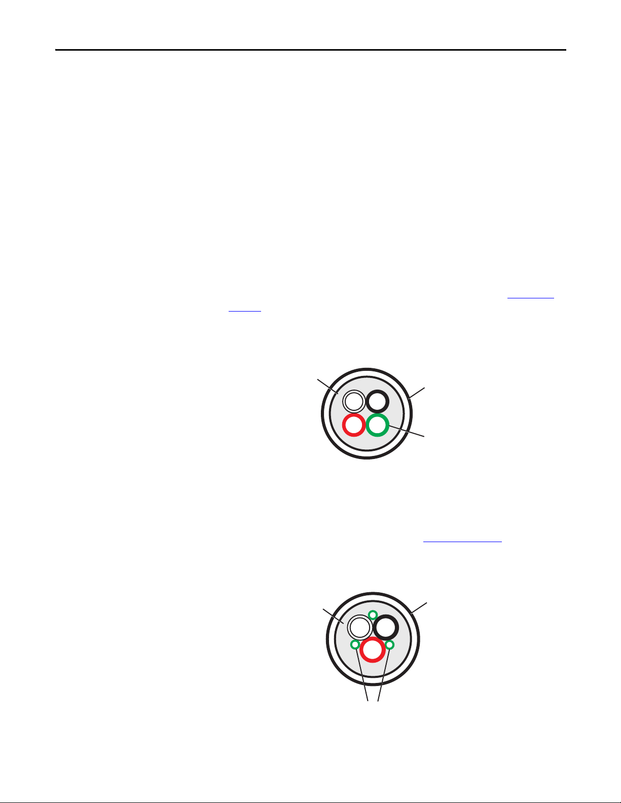
Number of Conductors
Local or national electrical codes can determine the required number of
conductors. Generally, these configurations are recommended:
• Figure 2
for drives up to and including 200 Hp (150 kW).
• Figure 3
for drives larger than 200 Hp (150 kW).
Space the ground conductors symmetrically around the power conductors. Verify
that the ground conductors are rated for full drive ampacity.
shows cable with a single ground conductor that is recommended
shows cable with three ground conductors that is recommended
Figure 2 - Cable with One Ground Conductor
W
G
BR
Figure 3 - Cable with Three Ground Conductors
Rockwell Automation Publication DRIVES-IN001M-EN-P - March 2014 13
Page 14
Chapter 1 Wire/Cable Types
Unacceptable
Accepta ble
Insulation Thickness and Concentricity
Wire must have an insulation thickness of ≥ 15 mil (0.4 mm/0.015 in.). The wire
insulation must not have significant variations of concentricity around the wire.
Figure 4 - Insulation Concentricity
Geometry
The physical relationship between individual conductors is important in drive
installations.
Individual conductors in conduit or cable trays have no fixed relationship and are
subject to cross coupling of noise, induced voltages, excess insulation stress, and
other possible interference.
Fixed geometry cable (cable that keeps the spacing and orientation of the
individual conductors constant) offers significant advantages over individual
loose conductors, including reduced cross-coupling noise and insulation stress.
Three types of fixed geometry, multi-conductor cables are discussed in this
section. See Unshielded Cable on page 15
Armored Cable on page 17
Table 1 - Recommended Cable Design
Type Max Wire Size Where Used Rating/Type Description
Type 1 2 AWG Standard installations
100 Hp or less
Type 2 2 AWG Standard installations
100 Hp or less
with brake conductors
Type 3 500 MCM AWG Standard installations
150 Hp or more
Type 4 500 MCM AWG Water, caustic chemical,
crush resistance
Type 5 500 MCM AWG 690V applications Tray-rated 2000V, 90 °C (194 °F) Three tinned copper conductors with XLPE insulation. Three bare copper
600V, 90 °C (194 °F)
XHHW2/RHW-2
600V, 90 °C (194 °F)
RHH/RHW-2
Tray-rated 600V, 90 °C (194 °F)
RHH/RHW-2
Tray-rated 600V, 90 °C (194 °F)
RHH/RHW-2
.
Four tinned copper conductors with cross-linked polyethylene (XLPE)
insulation
Four tinned copper conductors with XLPE insulation plus one shielded pair of
brake conductors.
Three tinned copper conductors with XLPE insulation and three bare copper
grounds and polyvinyl chloride (PVC) jacket.
Three bare copper conductors with XLPE insulation and three copper grounds
on 10 AWG and smaller. Acceptable in Class I and II, Division I and II locations.
grounds and PVC jacket.
IMPORTANT: If terminator network or output filter is used, connector
insulation must be XLPE, not PVC.
, Shielded Cable on page 16, and
14 Rockwell Automation Publication DRIVES-IN001M-EN-P - March 2014
Page 15
Wire/ Cable Typ es Chapter 1
Typ e 1 I nst al latio n, w ithout Brake Conductors
G
R
B
W
Single Ground
Conduc tor
PVC Outer
Sheath
Filler
Multiple Ground
Conducto rs
PVC Outer
Sheath
Filler
Unshielded Cable
Properly designed multi-conductor cable can provide superior performance in
wet applications, significantly reduce voltage stress on wire insulation, and reduce
cross coupling between drives.
The use of cables without shielding is generally acceptable for installations where
electrical noise created by the drive does not interfere with the operation of other
devices, such as communication cards, photoelectric switches, weigh scales, and
others. Verify that the installation does not require shielded cable to meet specific
electromagnetic compatibility (EMC) standards for CE, C-Tick, or FCC
requirements. Cable specifications depend on the installation type.
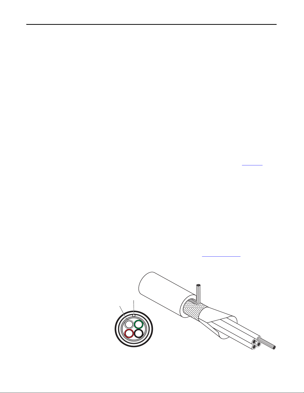
Type 1 and Type 2 Installation
Type 1 or Type 2 installations require 3-phase conductors and a fully rated
individual ground conductor with or without brake leads. Refer to Table 1 on
page 14 for detailed information and specifications on these installations.
Figure 5 - Type 1 Unshielded Multi-conductor Cable without Brake Leads
Type 3 Installation
Type 3 installation requires three symmetrical ground conductors whose
ampacity equals the phase conductor. Refer to Table 1 on page 14
information and specifications on this installation.
Figure 6 - Type 3 Unshielded Multi-Conductor Cable
G
B
W
G
Rockwell Automation Publication DRIVES-IN001M-EN-P - March 2014 15
G
R
for detailed
Page 16
Chapter 1 Wire/Cable Types
Shield
Drain Wire
Chose the outer sheathing and other mechanical characteristics to suit the
installation environment. Consider the surrounding air temperature, chemical
environment, flexibility, and other factors in all installation types.
Shielded Cable
Shielded cable contains all of the general benefits of multi-conductor cable with
the added benefit of a copper-braided shield that can contain much of the noise
generated by a typical AC drive. Use shielded cable for installations with sensitive
equipment, such as weigh scales, capacitive proximity switches, and other devices
that can be affected by electrical noise in the distribution system. Applications
with large numbers of drives in a single location, imposed EMC regulations, or a
high degree of communication/networking, are also good candidates for shielded
cable.
Shielded cable can also help reduce shaft voltage and induced bearing currents for
some applications. In addition, the increased size of shielded cable can help
extend the distance that the motor can be from the drive without the addition of
motor protective devices, such as terminator networks. Refer to Chapter 5
information regarding reflected wave phenomena.
for
Consider all of the general specifications dictated by the environment of the
installation, including temperature, flexibility, moisture characteristics, and
chemical resistance. In addition, include a braided shield specified by the cable
manufacturer as having coverage of at least 75%. An additional foil shield can
greatly improve noise containment.
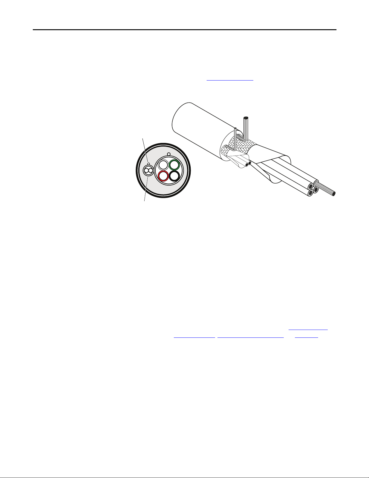
Type 1 Installation
An acceptable shielded cable for Type 1 installations has four XLPE insulated
conductors with a 100% coverage foil and an 85% coverage copper braided shield
(with drain wire) surrounded by a PVC jacket. For detailed specifications and
information on Type 1 installations, refer to Table 1 on page 14
Figure 7 - Type 1 Installation — Shielded Cable with Four Conductors
W
G
.
BR
16 Rockwell Automation Publication DRIVES-IN001M-EN-P - March 2014
Page 17
Wire/ Cable Typ es Chapter 1
B
R
G
W
Drain Wire for Brake
Conduc tor Shiel d
Shield for Brake
Condu ctors
TIP
Type 2 Installation
An acceptable shielded cable for Type 2 installations is essentially the same cable
as Type 1, plus one shielded pair of brake conductors. For more information on
Typ e 2 in sta llat io ns, re fe r to Table 1 on page 14
Figure 8 - Type 2 Installation — Shielded Cable with Brake Conductors
.
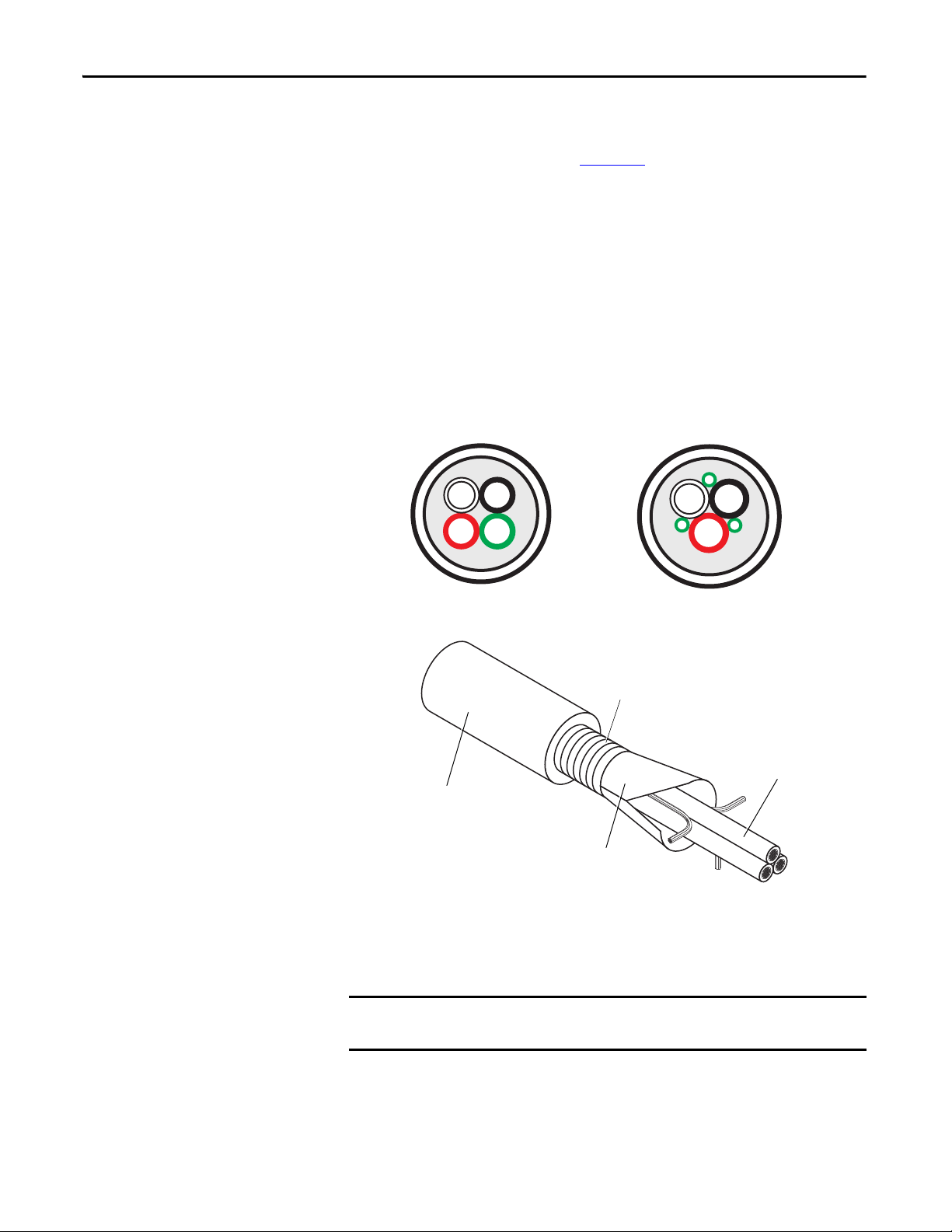
Type 3 Installation
These cables have 3 XLPE insulated copper conductors, 25% minimal overlap
with helical copper tape, and three bare copper grounds in PVC jacket.
Other types of shielded cable are available, but the selection of these types can
limit the allowable cable length. Particularly, some of the newer cables twist four
conductors of THHN wire and wrap them tightly with a foil shield. This
construction can greatly increase the cable charging current required and reduce
the overall drive performance. Unless specified in the individual distance tables
as tested with the drive, these cables are not recommended and their
performance against the lead length limits supplied is not known. For more
information about motor cable lead restrictions, refer to, Conduit on page 67
Moisture on page 72
, Effects On Wire Types on page 73, and Appendix A.
,
Armored Cable
Cable with continuous aluminum armor is often recommended in drive system
applications or specific industries. Armored cable offers most of the advantages of
standard shielded cable and also combines considerable mechanical strength and
resistance to moisture. It can be installed in concealed and exposed manners and
removes the requirement for conduit (electrical metallic tubing [EMT]) in the
installation. It can also be directly buried or embedded in concrete.
Rockwell Automation Publication DRIVES-IN001M-EN-P - March 2014 17
Page 18
Chapter 1 Wire/Cable Types
IMPORTANT
Cable with Three Ground Conductors
Cable with a Single Ground Conductor
G
R
B
W
Conduc tors wit h XLPE
Insulation
Optional Foil/Copper Tape
and/or Inner PVC Jacket
Armor
Optional PVC Outer Sheath
Because noise containment can be affected by incidental grounding of the armor
to building steel when the cable is mounted, we recommend that the armored
cable has an overall PVC jacket (see Chapter 2
).
Interlocked armor is acceptable for shorter cable runs, but continuous welded
armor is preferred. General recommendations for ground conductors are listed
here:
• Cable with a single ground conductor is sufficient for drive sizes up to and
including 200 Hp (150 kW).
• Cable with three ground conductors is recommended for drive sizes larger
than 200 Hp (150 kW).
Space the ground conductors symmetrically around the power conductors. Verify
that the ground conductors are rated for full drive ampacity.
G
B
W
G
G
R
Figure 9 - Armored Cable with Three Ground Conductors
A good example of cable for Type 5 installation is Anixter 7V-5003-3G. This
cable has three XLPE insulated copper conductors, 25% minimal overlap with
the helical copper tape, and three bare copper grounds in PVC jacket.
If a terminator network or output filter is used, the connector insulation must
be XLPE, and not PVC.
18 Rockwell Automation Publication DRIVES-IN001M-EN-P - March 2014
Page 19

Wire/ Cable Typ es Chapter 1
Stranded Neutral
PVC Outer
Sheath
Filler
European Style Cable
Cable used in many installations in Europe must conform to Low Voltage
Directive (LVD) 2006/95/EC. Generally recommended are flexible cables with a
bend radius of 20 times the cable diameter for movable cable, and 6 times the
cable diameter for fixed installations, with a screen (shield) of 70…85% coverage.
Insulation for both conductors and the outer sheath is PVC.
The number and color of individual conductors can vary, but the
recommendation is for three phase conductors (customer-preferred colors) and
one ground conductor (green/yellow).
Ölflex Classic 100SY, or Ölflex Classic 110CY, are examples.
Figure 10 - European Style Multi-conductor Cable
B
W
Input Power Cables
R
In general, the selection of cable for AC input power to a drive has no special
requirements. Some installations suggest shielded cable to prevent coupling of
noise onto the cable (see Chapter 2
), and in some cases shielded cable can be
required to meet noise standards, such as CE for Europe, C-Tick for Australia/
New Zealand, and others. This can be especially true if an input filter is required
to meet a standard. The user manual for the drive has the requirements for
meeting these types of standards. Additionally, individual industries can have
required standards due to environment or experience.
For AC variable frequency drive applications that must satisfy EMC standards
for CE, C-Tick, FCC, or others, we recommend the same type of shielded cable
that is specified for the AC motors be used between the drive and transformer.
Check the individual user manuals or system schematics for specific additional
requirements to meet EMC standards.
Rockwell Automation Publication DRIVES-IN001M-EN-P - March 2014 19
Page 20
Chapter 1 Wire/Cable Types
182.9 (600)
91.4 (300) 91.4 (300)
15.2 (50)
167.6 (550) 152.4 (500)
15.2 (50)15.2 (50)
All examples represent motor cable length of 182.9 m (600 ft)
IMPORTANT
Motor Cables
The majority of recommendations regarding drive cables are for issues caused by
the nature of the drive output. A PWM drive creates AC motor current by
sending DC voltage pulses to the motor in a specific pattern. These pulses affect
the wire insulation and can be a source of electrical noise. Consider the rise time,
amplitude, and frequency of these pulses when choosing a wire/cable type.
Consider these factors when choosing a cable:
• The effects of the drive output once the cable is installed.
• The need for the cable to contain noise caused by the drive output.
• The amount of cable charging current available from the drive.
• Possible voltage drop (and subsequent loss of torque) for long wire runs.
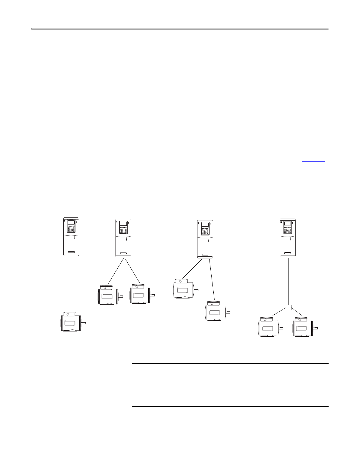
Keep the motor cable lengths within the limits set in the user manual for the
drive. Various issues, including cable charging current and reflected wave voltage
stress, can exist. If the cable restriction is listed because of excessive coupling
current, apply the methods to calculate total cable length, as shown in Figure 11
If the restriction is due to voltage reflection and motor protection, refer to
Appendix A
Figure 11 - Motor Cable Length for Capacitive Coupling
for exact distances allowed.
.
20 Rockwell Automation Publication DRIVES-IN001M-EN-P - March 2014
For multi-motor applications, review the installation carefully. Consult your
distributor drive specialist or Rockwell Automation when considering a
multi-motor application with greater than two motors. In general, most
installations have no issues. However, high peak cable charging currents can
cause drive over-currents or ground faults.
Page 21
Wire/ Cable Typ es Chapter 1
Cable for Discrete Drive I/O
Analog Signal and Encoder Cable
Discrete I/O, such as start and stop commands, can be wired to the drive with a
variety of cabling. We recommend shielded cable to reduce cross-coupled noise
from power cables. Standard individual conductors that meet the general
requirements for type, temperature, gauge, and applicable codes are acceptable if
they are routed away from higher voltage cables to minimize noise coupling.
However, multi-conductor cable can be less expensive to install. Separate control
wires from power wires by at least 0.3 m (1 ft)
Table 2 - Recommended Control Wire for Digital I/O
(1)
Type
Unshielded Per US NEC or applicable national or local code – 300V, 60 °C
Shielded Multi-conductor shielded cable 0.750 mm
(1) The cable choices shown are for 2-channel (A and B) or 3-channel (A,B, and Z) encoders. If high resolution or other types of
feedback devices are used, choose a similar cable with the correct gauge and number of conductor pairs.
Wire Type(s) Description Minimum
2
3-conductor, shielded.
(18 AWG),
Insulation Rating
(140 °F)
Always use shielded cable with copper wire. We recommend wire with an
insulation rating of 300V or greater. Separate analog signal wires from power
wires by at least 0.3 m (1 ft). Run encoder cables in a separate conduit. If signal
cables must cross power cables, cross at right angles. Terminate the shield of the
shielded cable as recommended by the manufacturer of the encoder or analog
signal device.
Table 3 - Recommended Signal Wire
Signal Type/
Where Used
Standard analog I/O – 0.750 mm2 (18 AWG), twisted pair, 100% shield
Remote pot – 0.750 mm2 (18 AWG), 3-conductor, shielded
Encoder/Pulse I/O
< 30.5 m (100 ft)
Encoder/Pulse I/O
30.5…152.4 m
(100…500 ft)
Encoder/Pulse I/O
152.4…259.1 m
(500…850 ft)
(1) If the wires are short and contained within a cabinet that has no sensitive circuits, the use of shielded wire is not always necessary,
but is recommended.
Wire
Type( s)
Combined 0.196 mm
Signal 0.196 mm2 (24 AWG), individually shielded
Power 0.750 mm
Combined 0.330 mm
Signal 0.196 mm2 (24 AWG), individually shielded
Power 0.750 mm
Combined 0.750 mm
Description Minimum
(1)
with drain
2
(24 AWG), individually shielded
2
(18 AWG)
2
or 0.500 mm
2
(18 AWG)
2
(18 AWG), individually shielded pair
2
Insulation Rating
300V,
75…90 °C
(167…194 °F)
Rockwell Automation Publication DRIVES-IN001M-EN-P - March 2014 21
Page 22

Chapter 1 Wire/Cable Types
Communication
This section provides cable recommendations for these communication
protocols:
• DeviceNet on page 22
• ControlNet on page 23
• Ethernet on page 23
• Remote I/O and Data Highway Plus (DH+) on page 24
• Serial (RS-232 and RS-485) on page 24
DeviceNet
DeviceNet cable options, topology, distances allowed, and techniques are specific
to the DeviceNet network. For more information, refer to DeviceNet Media
Design and Installation Guide, publication DNET-UM072
In general, the four cable types for DeviceNet media meet these criteria:
• Round (thick) cable with an outside diameter of 12.2 mm (0.48 in.);
normally used for trunk lines, but can also be used for drop lines.
• Round (thin) cable with an outside diameter of 6.9 mm (0.27 in.);
normally used for drop lines, but can also be used for trunk lines.
• Flat cable, normally used for trunk lines.
• KwikLink drop cable, used only in KwikLink systems.
.
Round cable contains these five wires:
• One twisted pair (red and black) for 24V DC power.
• One twisted pair (blue and white) for signal.
• One drain wire (bare).
Flat cable contains these four wires:
• One pair (red and black) for 24V DC power.
• One pair (blue and white) for signal.
Drop cable for KwikLink is a 4-wire, unshielded, gray cable.
The distance between points, installation of terminating resistors, and chosen
baud rate are significant to the installation. For more information, refer to the
DeviceNet Media Design and Installation Guide, publication DNET-UM072
.
22 Rockwell Automation Publication DRIVES-IN001M-EN-P - March 2014
Page 23

Wire/ Cable Typ es Chapter 1
ControlNet
ControlNet cable options, topology, distances allowed, and techniques are
specific to the ControlNet network. For more information, refer to the
ControlNet Coax Media Planning and Installation Guide, publication
CNET-IN002
Depending on the environment at the installation site, there are several types of
RG-6 quad shield cables that can be appropriate. The standard cable
recommended is Allen-Bradley catalog number 1786-RG6, Quad Shield coax.
Country, state, or local codes, such as the U.S. NEC, govern the installation.
Installation Environment Use this Cable Type
Light industrial • Standard PVC
Heavy ind ustrial • Lay-on armored
High/Low temperature or corrosive (harsh chemicals) • Plenum-FEP
Festooning or flexing • High flex
Moistu re: direct bu rial, with fl ooding compound, fungus resistant • Flood burial
.
• CM-CL2
• Light interlocking armor
• CMP-CL2P
The allowable length of segments and installation of terminating resistors play a
significant part in the installation. Refer to the ControlNet Coax Media
Planning and Installation Guide, publication CNET-IN002
, for details.
Ethernet
Ethernet communication interface wiring is very detailed for the type of cable,
connectors, and routing. In general, Ethernet systems use shielded twisted pair
(STP) cable, or unshielded twisted pair (UTP) cable, with RJ45 connectors that
meet the IP67 standard and are appropriate for the environment. Use cables that
meet Telecommunications Industry Association/Electronic Industries Alliance
(TIA/EIA) standards at industrial temperatures.
Shielded cable is recommended when the installation can include welding,
electrostatic processes, drives over 10 Hp, motor control centers (MCCs), high
power RF radiation, or devices carrying current in excess of 100 A. Shield
handling and single-point grounding, also discussed in this document, are also
important for the proper operation of Ethernet installations.
There are also important distance and routing limitations published in detail.
Rockwell Automation Publication DRIVES-IN001M-EN-P - March 2014 23
Page 24

Chapter 1 Wire/Cable Types
IMPORTANT
IMPORTANT
Remote I/O and Data Highway Plus (DH+)
Only Allen-Bradley catalog number 1770-CD shielded twinaxial cabling is
tested and approved for remote I/O and DH+ installations.
The maximum cable length depends on the baud rate.
Baud Rate Maximum Cable Length
57.6 Kbps 3048 m (10,000 ft)
115.2 Kbps 1524 m (5000 ft)
230.4 Kbps 762 m (2500 ft)
All three connections (blue, shield, and clear) must be connected at each node.
Do not connect in a star topology. Only two cables can be connected at any
wiring point. Use either series or daisy chain topology at all points.
Serial (RS-232 and RS-485)
Follow these recommended standard practices for serial communications wiring:
• One twisted pair and one signal common for RS-232.
• Two twisted pair, with each pair individually shielded, for RS-485.
24 Rockwell Automation Publication DRIVES-IN001M-EN-P - March 2014
Page 25
Chapter 2
Power Distribution
This chapter discusses different power distribution schemes and factors that can
affect drive performance.
System Configurations
The type of transformer and the connection configuration feeding the drive have
an important role in drive performance and safety. This section includes a brief
description of some of the more common configurations and their qualities and
shortcomings.
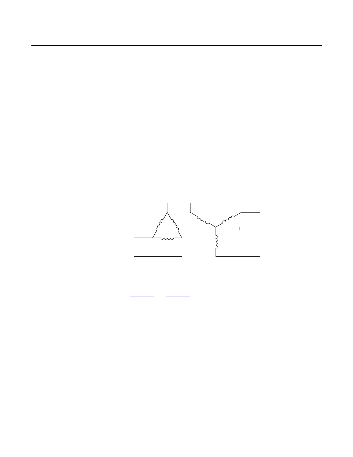
Delta/Wye with Grounded Wye Neutral
Delta/Wye wi th Grounde d Wye Neutr al is the most common type of
distribution system. It provides a 30° phase shift. The grounded neutral provides
a direct path for common mode current caused by the drive output (see
Chapter 3
Rockwell Automation recommends the use of grounded neutral systems for these
reasons:
and Chapter 6).
• Controlled path for common mode noise current
• Consistent line-to-ground voltage reference that minimizes insulation
stress
• Accommodation for system surge protection schemes
Rockwell Automation Publication DRIVES-IN001M-EN-P - March 2014 25
Page 26
Chapter 2 Power Distribution
or
Single-phase Loads
Single-phase Loads
Three-phase
Loads
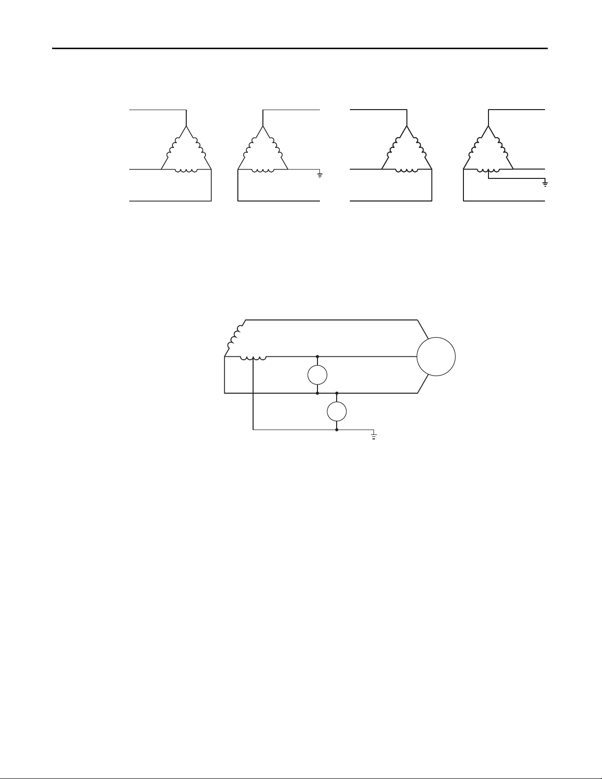
Delta/Delta with Grounded Leg, or Four-wire Connected Secondary Delta
Delta/Delta with Grounded Leg or Four-wire Connected Secondary Delta is a
common configuration with no phase shift between input and output. The
grounded center tap provides a direct path for common mode current caused by
the drive output.
Three-phase Open Delta with Single-phase Center Tapped
Three-phase Open Delta with Single-phase Center Tapped is a configuration
providing a Three-phase delta transformer with one side tapped. This tap (the
neutral) is connected to earth. The configuration is called the antiphase
grounded (neutral) system.
The open delta transformer connection is limited to 58% of the 240V,
single-phase transformer rating. Closing the delta with a third single-phase,
240V transformer provides full rating for the two single-phase, 240V
transformers.
The phase leg opposite the midpoint has an elevated voltage when compared to
earth or neutral. The hottest high leg must be positively identified throughout
the electrical system. Make the hottest high leg the center leg in any switch, motor
control, three-phase panel board, and so on. The NEC requires orange color tape
to identify this leg.
26 Rockwell Automation Publication DRIVES-IN001M-EN-P - March 2014
Page 27
Power Distribution Chapter 2
Ungrounded Secondary
ATT EN TI ON : Grounding the transformer secondary is essential to the safety of
personnel and safe operation of the drive. Leaving the secondary floating
causes dangerous high voltages between the chassis of the drive and the
internal power structure components. Exceeding the voltage rating of the
drive’s input metal oxide varistor (MOV) protection devices can cause a
catastrophic failure. In all cases, the input power to the drive is referenced to
ground.
If the system is ungrounded, other general precautions, such as a system level
ground fault detector or system level line to ground suppressor, can be necessary.
Or consider an isolation transformer with the secondary of the transformer
grounded.
Refer to local codes regarding safety requirements. Also refer to Surge Protection
MOVs and Common Mode Capacitors on page 45.
High Resistance Ground
Grounding the Wye Secondary Neutral through a resistor is an acceptable
method of grounding. Under a short circuit secondary condition, any of the
output phases to ground do not exceed the normal line-to-line voltage. This is
within the rating of the MOV input protection devices on the drive. The resistor
is often used to detect ground current by monitoring the associated voltage drop.
Because high frequency ground current can flow through this resistor, be sure to
properly connect the drive motor leads by using the recommended cables and
methods. In some cases, multiple drives (that can have one or more internal
references to ground) on one transformer can produce a cumulative ground
current that can trigger the ground fault interrupt circuit. Refer to Surge
Protection MOVs and Common Mode Capacitors on page 45.
Rockwell Automation Publication DRIVES-IN001M-EN-P - March 2014 27
Page 28

Chapter 2 Power Distribution
L1
L2
L3
PEN or N
PE
IMPORTANT
TN-S Five-wire System
TN-S Five-wire distribution systems are common throughout Europe, with the
exception of the United Kingdom and Germany. Leg-to-leg voltage (commonly
at 400V) powers three-phase loads. Leg-to-neutral voltage (commonly at 230V)
powers single-phase loads. Neutral is a current conducting wire, and connects
through a circuit breaker. The fifth wire is a separate ground wire. There is a
single connection between ground and neutral, typically in the distribution
system. Do not make connections between ground and neutral within the system
cabinets.
AC Line Voltage
AC Line Impedance
In general, all Allen-Bradley drives are tolerant to a wide range of AC line voltage.
Check the individual specifications for the drives you are installing.
Incoming voltage imbalances >2% can cause large unequal currents in a drive. Use
an input line reactor when line voltage imbalances are >2%.
To prevent excess current that can damage drives during events such as line
disturbances or certain types of ground faults, provide a minimum amount of
impedance in front of the drives. In many installations, this impedance comes
from the supply transformer and the supply cables. In some cases, an additional
transformer or reactor is recommended. If any of these conditions exist, consider
adding impedance (line reactor or transformer) in front of the drive:
• Installation site has switched power factor correction capacitors.
• Installation site has lightning strikes or voltage spikes in excess of 6000V
peak.
• Installation site has power interruptions or voltage dips in excess of
200V AC.
• The transformer is too large in comparison to the drive. See impedance
recommendations on Table 4 on page 30
through Table 13 on page 41.
Tab le s 4 through 13 define the largest transformer size for each product
and rating based on specific differences in construction, and is the
28 Rockwell Automation Publication DRIVES-IN001M-EN-P - March 2014
preferred method to follow.
Page 29

Power Distribution Chapter 2
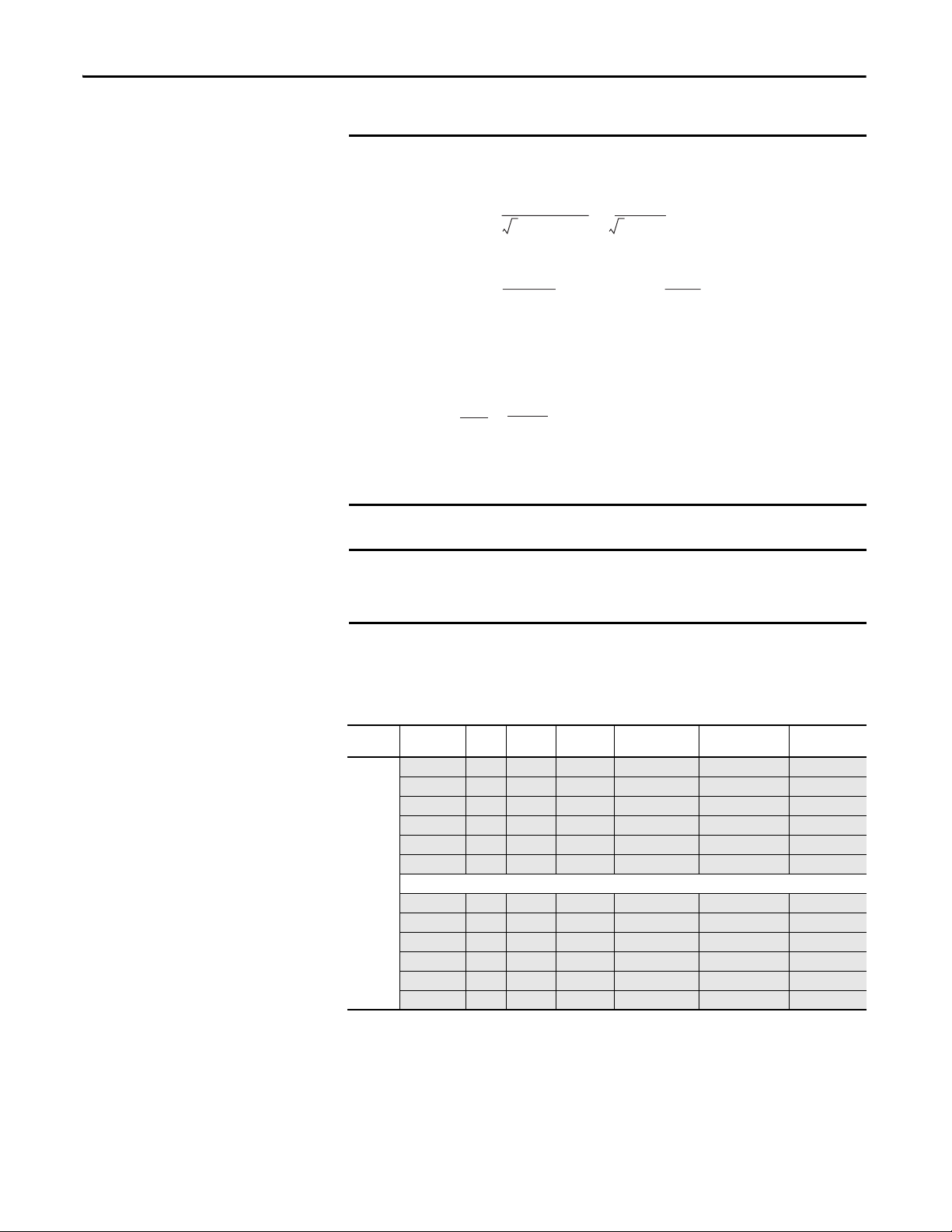
% impedance is the nameplate impedance of the transformer.
Typical values range from 0.03 (3%) to 0.06 (6%).
Z
xfmr
=
(V
line-line
)
2
VA
* % Impedance
or
% impedance is the nameplate impedance of the transformer.
Typical values range from 0.03 (3%) to 0.06 (6%).
Otherwise, use one of the following more conservative methods:
• For drives without built-in inductors – add line impedance whenever the
transformer kVA is more than 10 times larger than the drive kVA, or the
percent source impedance relative to each drive is less than 0.5%.
• For drives with built-in inductors – add line impedance whenever the
transformer kVA is more than 20 times larger than the drive kVA, or the
percent source impedance relative to each drive is less than 0.25%.
To identify drives with built-in inductors, see the product specific information in
Table 4 on page 30
through Table 13 on page 41. The shaded rows identify
products ratings without built-in inductors.
Use these equations to calculate the impedance of the drive and transformer:
Drive Impedance (in ohms)
V
Z
=
drive
3 * I
line-line
input-rating
Transformer Impedance (in ohms)
V
line-line
Z
=
xfmr
3 * I
* % Impedance
xfmr-rated
Transformer Impedance (in ohms)
V
line-line
Z
=
xfmr
3 * I
* % Impedance
xfmr-rated
Rockwell Automation Publication DRIVES-IN001M-EN-P - March 2014 29
Page 30
Chapter 2 Power Distribution
EXAMPLE
IMPORTANT
Z
xfmr
Z
drive
0.2304
102.6
= 0.00224 = 0.22%=
The drive is rated 1 Hp, 480V, 2.7A input.
The supply transformer is rated 50,000 VA (50 kVA), 5% impedance.
V
(V
line-line
3 * I
input-rating
2
)
line-line
* % Impedance =
VA
Z
=
drive
=
Z
xfmr
480V
= = 102.6 Ohms
3 * 2.7
2
480
* 0.05 = 0.2304 Ohms
50,000
Note that the percent (%) impedance has to be in per unit (5% becomes 0.05)
for the formula.
0.22% is less than 0.5%. Therefore, this transformer is too big for the drive.
Consider adding a line reactor.
Grouping multiple drives on one reactor is acceptable; however, the reactor
percent impedance must be large enough when evaluated for each drive
separately, not evaluated for all loads connected at once.
These recommendations are advisory and do not address all situations. Site
specific conditions must be considered to assure a quality installation.
Table 4 - AC Line Impedance Recommendations for Bulletin 160 Drives
Bulletin
Number
160
(1) Shaded rows identify drive ratings without built-in inductors.
(2) Maximum suggested KVA supply without consideration for additional inductance.
Drive Catalog
Number
-AA02 240 0.37(0.5) 15 3R4-B 6.5 4
-AA03 240 0.55 (0.75) 20 3R4-A 3 4
-AA04 240 0.75 (1) 30 3R4-A 3 4
-AA08 240 1.5 (2) 50 3R8-A 1.5 8
-AA12 240 2.2 (3) 75 3R12-A 1.25 12
-AA18 240 3.7 (5) 100 3R18-A 0.8 18
-BA01 480 0.37(0.5) 15 3R2-B 20 2
-BA02 480 0.55 (0.75) 20 3R2-A 12 2
-BA03 480 0.75 (1) 30 3R2-A 12 2
-BA04 480 1.5 (2) 50 3R4-B 6.5 4
-BA06 480 2.2 (3) 75 3R8-B 3 8
-BA10 480 3.7 (5) 100 3R18-B 1.5 18
Volts kW (H p) Max Sup ply
(1)
kVA
(2)
3% Line Reactor
Open Style 1321-
Reactor Inductance
(mH)
Reactor Current
Rating (amps)
30 Rockwell Automation Publication DRIVES-IN001M-EN-P - March 2014
Page 31

Table 5 - AC Line Impedance Recommendations for Bulletin 1305 Drives
Power Distribution Chapter 2
Bulletin
Number
1305
(1) Shaded rows identify drive ratings without built-in inductors.
(2) Maximum suggested KVA supply without consideration for additional inductance.
Drive Catalog
Number
-AA02A 240 0.37(0.5) 15 3R4-A 3 4
-AA03A 240 0.55 (0.75) 20 3R4-A 4 4
-AA04A 240 0.75 (1) 30 3R8-A 1.5 8
-AA08A 240 1.5 (2) 50 3R8-A 1.5 8
-AA12A 240 2.2 (3) 75 3R18-A 0.8 18
-BA01A 480 0.37 (0.5) 15 3R2-B 20 2
-BA02A 480 0.55 (0.75) 20 3R2-B 20 2
-BA03A 480 0.75 (1) 30 3R4-B 6.5 4
-BA04A 480 1.5 (2) 50 3R4-B 6.5 4
-BA06A 480 2.2 (3) 75 3R8-B 3 8
-BA09A 480 3.7 (5) 100 3R18-B 1.5 18
Volts kW (H p) Max Sup ply
(1)
kVA
(2)
3% Line Reactor
Open Style 1321-
Reactor Inductance
(mH)
Table 6 - AC Line Impedance Recommendations for PowerFlex 4 Drives
Drive Drive Catalog
PowerF lex
4
Number
22AB1P5 240 0.2 (0.25) 15 3R2-A 12 2
22AB2P3 240 0.4 (0.5) 25 3R4-B 6.5 4
22AB4P5 240 0.75 (1.0) 50 3R8-B 3 8
22AB8P0 240 1.5 (2.0) 100 3R8-A 1.5 8
22AB012 240 2.2 (3.0) 125 3R12-A 1.25 12
22AB017 240 3.7 (5.0) 150 3R18-A 0.8 18
Volts kW (H p) Max Sup ply
(1)
kVA
3% Line Reactor
Open Style 1321-
Reactor Inductance
(mH)
Reactor Current
Rating (amps)
Reactor Current
Rating (amps)
22AD1P4 480 0.4 (0.5) 15 3R2-B 20 2
22AD2P3 480 0.75 (1.0 ) 30 3R4-C 9 4
22AD4P0 480 1.5 (2.0) 50 3R4-B 6.5 4
22AD6P0 480 2.2 (3.0) 75 3R8-C 5 8
22AD8P7 480 3.7 (5.0) 100 3R8-B 3 8
(1) Shaded rows identify drive ratings without built-in inductors.
Rockwell Automation Publication DRIVES-IN001M-EN-P - March 2014 31
Page 32

Chapter 2 Power Distribution
Table 7 - AC Line Impedance Recommendations for PowerFlex 40 Drives
Drive Drive Catalog
PowerF lex
40
(1) Shaded rows identify drive ratings without built-in inductors.
(2) Maximum suggested KVA supply without consideration for additional inductance.
Number
22BB2P3 240 0.4 (0.5) 25 3R4-B 6.5 4
22BB5P0 240 0.75 (1.0) 50 3R8-B 3 8
22BB8P0 240 1.5 (2.0) 50 3R8-A 1.5 8
22BB012 240 2.2 (3.0) 50 3R12-A 1.25 12
22BB017 240 3.7 (5.0) 50 3R18-A 0.8 18
22BB024 240 5.5 (7.5) 100 3R25-A 0.5 25
22BB033 240 7.5 (10.0) 150 3R3 5-A 0.4 35
22BD1P4 480 0.4 (0.5) 15 3R2-B 20 2
22BD2P3 480 0.75 (1.0) 30 3R4-C 9 4
22BD4P0 480 1.5 (2.0) 50 3R4-B 6.5 4
22BD6P0 480 2.2 (3.0) 75 3R8-C 5 8
22BD010 480 3.7 (5.0) 100 3R8-B 3 8
22BD012 480 5.5 (7.5) 120 3R12-B 2.5 12
22BD017 480 7.5 (10.0) 150 3R18-B 1.5 18
22BD024 480 11.0 (15.0) 200 3R25-B 1.2 25
22BE1P7 600 0.75 (1.0) 20 3R2-B 20 2
22BE3P0 600 1.5 (2.0) 30 3R4-B 6.5 4
22BE4P2 600 2.2 (3.0) 50 3R4-B 6.5 4
22BE6P6 600 3.7 (5.0) 75 3R8-C 5 8
22BE9P9 600 5.5 (7.5) 120 3R12-B 2.5 12
22BE012 600 7.5 (10.0) 150 3R12-B 2.5 12
22BE019 600 11.0 (15.0) 200 3R18-B 1.5 18
Volts kW (Hp) Max Supply
(1)
kVA
(2)
3% Line Reactor
Open Style 1321-
Reactor Inductance
(mH)
Reactor Current
Rating (amps)
32 Rockwell Automation Publication DRIVES-IN001M-EN-P - March 2014
Page 33

Power Distribution Chapter 2
Table 8 - AC Line Impedance Recommendations for PowerFlex 400 Drives
Drive Drive Catalog
PowerF lex
400
(1) Shaded rows identify drive ratings without built-in inductors.
(2) Maximum suggested KVA supply without consideration for additional inductance.
Number
22CB012 240 2.2 (3.0) 50 3R12-A N/A N/A
22CB017 240 3.7 (5.0) 50 3R18-A N/A N/A
22CB024 240 5.5 (7.5) 200 3R25-A 0.5 25
22CB033 240 7.7 (10.0) 275 3R35-A 0.4 35
22CB049 240 11 (15.0) 350 3R45-A 0.3 45
22CB065 240 15 (20.0) 425 3R55-A 0.25 55
22CB075 240 18.5 (25.0) 550 3R80-A 0.2 80
22CB090 240 22 (30.0) 600 3R100-A 0.15 100
22CB120 240 30 (40.0) 750 3R130-A 0.1 130
22CB145 240 37 (50.0) 800 3R160-A 0.075 160
22CD6P0 480 2.2 (3.0) N/A N/A N/A N/A
22CD010 480 3.7 (5.0) N/A N/A N/A N/A
22CD012 480 5.5 (7.5) N/A N/A N/A N/A
22CD017 480 7.5 (10) N/A N/A N/A N/A
22CD022 480 11 (15) N/A N/A N/A N/A
22CD030 480 15 (20) N/A N/A N/A N/A
22CD038 480 18.5 (25) N/A N/A N/A N/A
22CD045 480 22 (30) N/A N/A N/A N/A
22CD060 480 30 (40) N/A N/A N/A N/A
22CD072 480 37 (50) N/A N/A N/A N/A
22CD088 480 45 (60) N/A N/A N/A N/A
22CD105 480 55 (75) N/A N/A N/A N/A
22CD142 480 75 (100) N/A N/A N/A N/A
22CD170 480 90 (125) N/A N/A N/A N/A
22CD208 480 110 (150) N/A N/A N/A N/A
Volts kW (Hp) Max Supply
(1)
kVA
(2)
3% Line Reactor
Open Style 1321-
Reactor Inductance
(mH)
Reactor Current
Rating (amps)
Rockwell Automation Publication DRIVES-IN001M-EN-P - March 2014 33
Page 34

Chapter 2 Power Distribution
Table 9 - AC Line Impedance Recommendations for PowerFlex 525 Drives
Drive Drive Catalog
PowerF lex
525
(1)
Number
25BB2P5 240 0.4 (0.5) 25 3R4-B 6.5 4
25BB5P0 240 0.75 (1.0) 50 3R8-B 3 8
25BB8P0 240 1.5 (2.0) 50 3R8-A 1.5 8
25BB012 240 2.2 (3.0) 50 3R12-A 1.25 12
25BB017 240 3.7 (5.0) 50 3R18-A 0.8 18
25BB024 240 5.5 (7.5) 100 3R25-A 0.5 25
25BB032 240 7.5 (10.0) 150 3R35-A 0.4 35
25BB048 240 11.0 (15.0) 150 3R55-B 0.5 55
25BB062 240 7.5 (10.0) 150 3R80-B 0.4 80
25BD1P4 480 0.4 (0.5) 15 3R2-B 20 2
25BD2P3 480 0.75 (1.0) 30 3R4-C 9 4
25BD4P0 480 1.5 (2.0) 50 3R4-B 6.5 4
25BD6P0 480 2.2 (3.0) 75 3R8-C 5 8
25BD010 480 3.7 (5.0) 100 3R8-B 3 8
25BD013 480 5.5 (7.5) 120 3R12-B 2.5 12
25BD017 480 7.5 (10.0) 150 3R18-B 1.5 18
25BD024 480 11.0 (15.0) 200 3R25-B 1.2 25
25BD030 480 15.0 (20.0) 200 3R35-B 0.8 35
25BD037 480 18.5 (25.0) 500 3R45-B 0.7 45
25BD043 480 22 (30.0) 500 3R45-B 0.7 45
Volts kW (H p) Max Sup ply
kVA
(2)
3% Line Reactor
Open Style 1321-
Reactor Inductance
(mH)
Reactor Current
Rating (amps)
25BE0P9 600 0.40(0.5) 20 3R2-B 20 2
25BE1P7 600 0.75 (1.0) 20 3R2-B 20 2
25BE3P0 600 1.5 (2.0) 30 3R4-B 6.5 4
25BE4P2 600 2.2 (3.0) 50 3R4-B 6.5 4
25BE6P6 600 3.7 (5.0) 75 3R8-C 5 8
25BE9P9 600 5.5 (7.5) 120 3R12-B 2.5 12
25BE012 600 7.5 (10.0) 150 3R12-B 2.5 12
25BE019 600 11.0 (15.0) 200 3R18-B 1.5 18
25BE022 600 15.0 (20.0) 200 3R25-B 1.2 25
25BE027 600 18.5 (25.0) 500 3R35-B 0.8 35
25BE032 600 22 (30.0) 500 3R35-B 0.8 35
(1) Shaded rows identify drive ratings without built-in inductors.
(2) Maximum suggested KVA supply without consideration for additional inductance.
34 Rockwell Automation Publication DRIVES-IN001M-EN-P - March 2014
Page 35

Power Distribution Chapter 2
Table 10 - AC Line Impedance Recommendations for PowerFlex 70 Drives
Drive Drive Catalog
Number
Volts kW (Hp) Max Supply
(1)
kVA
(2)
3% Line Reactor
Open Style 1321-
Reactor Inductance
(mH)
PowerF lex 7020AB2P2 240 0.37 (0.5) 25 3R2-D 6 2
20AB4P2 240 0.75 (1) 50 3R4-A 3 4
20AB6P8 240 1.5 (2) 50 3R8-A 1.5 8
20AB9P6 240 2.2 (3) 50 3R12-A 1.25 12
20AB015 240 4.0 (5) 200 3R18-A 0.8 18
20AB022 240 5.5 (7.5) 250 3R25-A 0.5 25
20AB028 240 7.5 (10) 300 3R3 5-A 0.4 35
20AB042 240 11 (15) 1000 3R4 5-A 0.3 45
20AB054 240 15 (20) 1000 3R8 0-A 0.2 80
20AB070 240 18.5 (25) 1000 3R80-A 0.2 80
20AC1P3 400 0.37 (0.5) 30 3R2-B 20 2
20AC2P1 400 0.75 (1) 50 3R2-B 20 2
20AC3P4 400 1.5 (2) 50 3R4-B 6.5 4
20AC5P0 400 2.2 (3) 75 3R4-B 6.5 4
20AC8P0 400 4.0 (5) 100 3R8-B 3 8
20AC011 400 5.5 (7.5) 250 3R12-B 2.5 12
20AC015 400 7.5 (10) 250 3R18-B 1.5 18
20AC022 400 11 (15) 300 3R25-B 1.2 25
20AC030 400 15 (20) 400 3R35-B 0.8 35
20AC037 400 18.5 (25) 750 3R35-B 0.8 35
20AC043 400 22 (30) 1000 3R45-B 0.7 45
20AC060 400 30 (40) 1000 3R55-B 0.5 55
20AC072 400 37 (50) 1000 3R80-B 0.4 80
Reactor Current
Rating (amps)
(3)
continued
20AD1P1 480 0.37 (0.5) 30 3R2 -B 20 2
20AD2P1 480 0.75 (1) 50 3R2-B 20 2
20AD3P4 480 1.5 (2) 50 3R4-B 6.5 4
20AD5P0 480 2.2 (3) 75 3R4-B 6.5 4
20AD8P0 480 3.7 (5) 100 3R8 -B 3 8
20AD011 480 5.5 (7.5) 250 3R12-B 2.5 12
20AD015 480 7.5 (10) 250 3R18-B 1.5 18
20AD022 480 11 (15) 300 3R25-B 1.2 25
20AD027 480 15 (20) 400 3R35-B 0.8 35
20AD034 480 18.5 (25) 750 3R35-B N/A N/A
20AD040 480 22 (30) 1000 3R45-B N/A N/A
20AD052 480 30 (40) 1000 3R55-B N/A N/A
20AD065 480 37 (50) 1000 3R80-B N/A N/A
20AE0P9 600 0.37 (0.5) 30 3R2-B 20 2
20AE1P7 600 0.75 (1) 50 3R2-B 20 2
20AE2P7 600 1.5 (2) 50 3R4-C 9 4
20AE3P9 600 2.2 (3) 75 3R4- C 9 4
20AE6P1 600 4.0 (5) 100 3R8-C 5 8
20AE9P0 600 5.5 (7.5) 250 3R8-B 3 8
20AE011 600 7.5 (10) 250 3R12-B 2.5 12
20AE017 600 11 (15) 300 3R18-B 1.5 18
20AE022 600 15 (20) 400 3R25-B 1.2 25
20AE027 600 18.5 (25) 1000 3R35-B 0.8 35
Rockwell Automation Publication DRIVES-IN001M-EN-P - March 2014 35
Page 36

Chapter 2 Power Distribution
Table 10 - AC Line Impedance Recommendations for PowerFlex 70 Drives (Continued)
Drive Drive Catalog
Number
Volts kW (Hp) Max Supply
(1)
kVA
(2)
3% Line Reactor
Open Style 1321-
Reactor Inductance
(mH)
PowerF lex 7020AE031 600 22 (30) 1000 3R35-B 0.8 35
20AE042 600 30 (40) 1000 3R45-B 0.7 45
20AE051 600 37 (50) 1000 3R55-B 0.5 55
(1) Shaded rows identify drive ratings without built-in inductors.
(2) Maximum suggested KVA supply without consideration for additional inductance.
(3) N/A = not available at time of printing.
Table 11 - AC Line Impedance Recommendations for PowerFlex 700/700S Drives
Drive Drive Catalog
PowerF lex
700/700S
For
PowerF lex
700S,
replace 20B
with 20D.
Number
20BB2P2 240 0.37 (0.5) 100 3R2-D 6 2
20BB4P2 240 0.75 (1) 125 3R4-A 3 4
20BB6P8 240 1.5 (2) 200 3R8-A 1.5 8
20BB9P6 240 2.2 (3) 300 3R12-A 1.25 12
20BB015 240 3.7 (5) 400 3R18-A 0.8 18
20BB022 240 5.5 (7.5) 500 3R25-A 0.5 25
20BB028 240 7.5 (10) 750 3R35-A 0.4 35
20BB042 240 11 (15) 1000 3R45-A 0.3 45
20BB052 240 15 (20) 1000 3R80-A 0.2 80
20BB070 240 18.5 (25) 1000 3R8 0-A 0.2 80
20BB080 240 22 (30) 1000 3R100-A 0.15 100
20BB104 240 30 (40) 1000 3R130-A 0.1 130
20BB130 240 37 (50) 1000 3R130-A 0.1 130
20BB154 240 45 (60) 1000 3R160-A 0.075 160
20BB192 240 55 (75) 1000 3R200-A 0.055 200
20BB260 240 75 (100) 1000 3R320-A 0.04 320
Volts kW (Hp) Max Supply
KVA
(1)
3% Line Reactor
Open Style 1321-
Reactor Inductance
(mH)
Reactor Current
Rating (amps)
Reactor Current
Rating (amps)
(3)
continued
20BC1P3 400 0.37 (5) 250 3R2-B 20 2
20BC2P1 400 0.75 (1) 250 3R2-B 20 2
20BC3P5 400 1.5(2) 500 3R4-B 6.5 4
20BC5P0 400 2.2 (3) 500 3R4-B 6.5 4
20BC8P7 400 4 (5) 500 3R8 -B 3 8
20BC011 400 5.5 (7.5) 750 3R1 2-B 2.5 12
20BC015 400 7.5 (10) 1000 3R18-B 1.5 18
20BC022 400 11 (15) 1000 3R25-B 1.2 25
20BC030 400 15 (20) 1000 3R35-B 0.8 35
20BC037 400 18.5(25) 1000 3R45-B 0.7 45
20BC043 400 22 (30) 1000 3R45-B 0.7 45
20BC056 400 30 (40) 1000 3R55-B 0.5 55
20BC072 400 37 (50) 1000 3R80-B 0.4 80
20BC085 400 45 (60) 1000 3R130-B 0.2 130
20BC105 400 55 (75) 1000 3R130-B 0.2 130
20BC125 400 55 (75) 1000 3R130-B 0.2 130
20BC140 400 75 (100) 1000 3R160-B 0.15 160
20BC170 400 90 (125) 1500 3R200-B 0.11 200
20BC205 400 110 (150) 1500 3R200- B 0.11 200
20BC260 400 132 (175) 2000 3RB32 0-B 0.075 320
36 Rockwell Automation Publication DRIVES-IN001M-EN-P - March 2014
Page 37

Power Distribution Chapter 2
Table 11 - AC Line Impedance Recommendations for PowerFlex 700/700S Drives (Continued)
Drive Drive Catalog
PowerF lex
700/700S
For
PowerF lex
700S,
replace 20B
with 20D.
(1) Maximum suggested KVA supply without consideration for additional inductance
Number
20BD1P1 480 0.37 (0.5) 250 3R2-B 20 2
20BD2P1 480 0.75 (1) 250 3R2-B 20 2
20BD3P4 480 1.5 (2) 500 3R4-B 6.5 4
20BD5P0 480 2.2 (3) 500 3R4-B 6.5 4
20BD8P0 480 4.0 (5) 500 3R8-B 3 8
20BD011 480 5.5 (7.5) 750 3R12-B 2.5 12
20BD014 480 7.5 (10) 750 3R18-B 1.5 18
20BD022 480 11 (15) 750 3R25-B 1.2 25
20BD027 480 15 (20) 750 3R35-B 0.8 35
20BD034 480 18.5 (25) 1000 3R35-B 0.8 35
20BD040 480 22 (30) 1000 3R45-B 0.7 45
20BD052 480 30 (40) 1000 3R55-B 0.5 55
20BD065 480 37 (50) 1000 3R80-B 0.4 80
20BD077 480 45 (60) 1000 3R80-B 0.4 80
20BD096 480 55 (75) 1000 3R100- B 0.3 100
20BD125 480 75 (100) 1000 3R1 30-B 0.2 130
20BD140 480 75 (100) 1000 3R1 60-B 0.15 160
20BD156 480 90 (125) 1500 3R1 60-B 0.15 160
20BD180 480 110 (150) 1500 3R200-B 0.11 200
20BE0P9 600 0.37 (0.5) 250 3R2 -B 20 2
20BE1P7 600 0.75 (1) 250 3R2-B 20 2
20BE2P7 600 1.5 (2) 500 3R4-B 6.5 4
20BE3P9 600 2.2 (3) 500 3R4-B 6.5 4
20BE6P1 600 4.0 (5) 500 3R8 -B 3 8
20BE9P0 600 5.5 (7.5) 750 3R8 -B 3 8
20BE011 600 7.5 (10) 750 3R1 2-B 2.5 12
20BE017 600 11 (15) 750 3R25-B 1.2 25
20BE022 600 15 (20) 750 3R25-B 1.2 25
20BE027 600 18.5 (25) 1000 3R35-B 0.8 35
20BE032 600 22 (30) 1000 3R35-B 0.8 35
20BE041 600 30 (40) 1000 3R45-B 0.7 45
20BE052 600 37 (50) 1000 3R55-B 0.5 55
20BE062 600 45 (60) 1000 3R80-B 0.4 80
20BE077 600 55 (75) 1000 3R80-B 0.4 80
20BE099 600 75 (100) 1200 3R1 00-B 0.3 100
20BE125 600 90 (125) 1400 3R1 30-B 0.2 130
20BE144 600 110 (150) 1500 3R160-B 0.15 160
Volts kW (Hp) Max Supply
KVA
(1)
3% Line Reactor
Open Style 1321-
Reactor Inductance
(mH)
Reactor Current
Rating (amps)
Rockwell Automation Publication DRIVES-IN001M-EN-P - March 2014 37
Page 38

Chapter 2 Power Distribution
Table 12 - AC Line Impedance Recommendations for PowerFlex 753/755 Drives
Drive Drive Catalog
PowerF lex
753/755
For
PowerF lex
753,
replace 20G
with 20F.
Number
20G_RC2P1 400 0.75 (1) 250 3R2-B 20 2
20G_RC3P5 400 1.5(2) 500 3R4-B 6.5 4
20G_RC5P0 400 2.2 (3) 500 3R4-B 6.5 4
20G_RC8P7 400 4 (5) 500 3R8-B 3 8
20G_RC011 400 5.5 (7.5) 750 3R12-B 2.5 12
20G_RC015 400 7.5 (10) 1000 3R18- B 1.5 18
20G_C2P1 400 0.75 (1) 250 3R2-B 20 2
20G_C3P5 400 1.5(2) 500 3R4-B 6.5 4
20G_C5P0 400 2.2 (3) 500 3R4-B 6.5 4
20G_C8P7 400 4 (5) 500 3R8-B 3 8
20G_C011 400 5.5 (7.5 ) 750 3R12- B 2.5 12
20G_C015 400 7.5 (10) 1000 3R18-B 1.5 18
20G_C022 400 11 (15) 1000 3R25- B 1.2 25
20G_C030 400 15 (20) 1000 3R35- B 0.8 35
20G_C037 400 18.5(25) 1000 3R45- B 0.7 45
20G_C043 400 22 (30) 1000 3R45- B 0.7 45
20G_C060 400 30 (40) 1000 3R80- B 0.4 80
20G_C072 400 37 (50) 1000 3R80- B 0.4 80
20G_C085 400 45 (60) 1000 3R130 -B 0.2 130
20G_C105 400 55 (75) 1000 3R130 -B 0.2 130
20G_C125 400 55 (75) 1000 3R130 -B 0.2 130
20G_C140 400 75 (100) 1000 3R160-B 0.15 160
20G_C170 400 90 (125) 1500 3R200-B 0.11 200
20G_C205 400 110 (150) 2000 3R200-B 0.11 200
20G_C260 400 132 (175) 2500 3RB320-B 0.075 320
20G_C302 400 160 (214) 2500 3RB320-B 0.075 320
20G_C367 400 200 (268) 3000 3RB400-B 0.06 400
20G_C456 400 250 (335) 3500 3R500-B 0.05 500
20G_C460 400 250 (335) 3500 3R500-B 0.05 500
20G_C567 400 315(422) 400 0 3R600-B 0.04 600
20G_C650 400 355 (476) 4500 3R750-B 0.029 750
20G_C750 400 400 (536) 4500 3R750-B 0.029 750
20G_C770 400 400(536) 500 0 3R850-B 0.027 850
20G_C1K0 400 500 (670) 5000 3R1000-B 0.022 1000
20G_C1K2 400 560 (750) 5000 2 x 3R750-B 0.015 1500
20G_C1K4 400 630 (175) 5000 2 x 3R750-B 0.015 1500
20G_C1K5 400 850 (1070) 5000 2 x 3R850-B 0.014 1700
20G_C1K6 400 900 (1200) 5000 2 x 3R850-B 0.014 1700
20G_C2K1 400 1250 (1675) 5000 2 x 3R1000-B 0.011 2000
Volts kW (Hp) Max Supply
KVA
(1)
3% Line Reactor
Open Style 1321-
Reactor Inductance
(mH)
Reactor Current
Rating (amps)
20G_RD2P1 480 0.75 (1) 250 3R 2-B 20 2
20G_RD3P4 480 1.5(2) 500 3R4-B 6.5 4
20G_RD5P0 480 2.2 (3) 500 3R4-B 6.5 4
20G_RD8P0 480 4 (5) 500 3R 8-B 3 8
20G_RD011 480 5.5 (7.5) 750 3R12-B 2.5 12
20G_RD014 480 7.5 (10) 100 0 3R18-B 1.5 18
20G_D2P1 480 0.75 (1) 250 3R2-B 20 2
20G_D3P4 480 1.5 (2) 500 3R4-B 6.5 4
continued
38 Rockwell Automation Publication DRIVES-IN001M-EN-P - March 2014
Page 39

Power Distribution Chapter 2
Table 12 - AC Line Impedance Recommendations for PowerFlex 753/755 Drives (Continued)
Drive Drive Catalog
PowerF lex
753/755
For
PowerF lex
753,
replace 20G
with 20F.
Number
20G_D5P0 480 2.2 (3) 500 3R4-B 6.5 4
20G_D8P0 480 4.0 (5) 500 3R8-B 3 8
20G_D011 480 5.5 (7.5) 750 3R12- B 2.5 12
20G_D014 480 7.5 (10) 750 3R18-B 1.5 18
20G_D022 480 11 (15) 750 3R 25-B 1.2 25
20G_D027 480 15 (20) 750 3R 35-B 0.8 35
20G_D034 480 18.5 (25) 1000 3R35-B 0.8 35
20G_D040 480 22 (30) 1000 3R45-B 0.7 45
20G_D052 480 30 (40) 1000 3R55-B 0.5 55
20G_D065 480 37 (50) 1000 3R80-B 0.4 80
20G_D077 480 45 (60) 1000 3R80-B 0.4 80
20G_D096 480 55 (75) 1000 3R100-B 0.3 100
20G_D125 480 75 (100) 1000 3R130-B 0.2 130
20G_D140 480 75 (100) 1000 3R160-B 0.15 160
20G_D156 480 90 (125) 1500 3R160-B 0.15 160
20G_D186 480 110 (150) 1500 3R200-B 0.11 200
20G_D248 480 150 (200) 2000 3RB320-B 0.075 320
20G_D302 480 187(250) 2500 3RB320-B 0.075 320
20G_D361 480 224 (300) 2500 3RB400-B 0.06 400
20G_D415 480 260 (350) 3000 3R500-B 0.05 500
20G_D430 480 260 (350) 3500 3R500-B 0.05 500
20G_D485 480 298 (400) 3500 3R600-B 0.04 600
20G_D545 480 336(450) 4000 3R600-B 0.04 600
20G_D617 480 373 (500) 4500 3R750-B 0.029 750
20G_D710 480 448 (600) 4500 3R750-B 0.029 750
20G_D740 480 485 (650) 4500 3R750-B 0.029 750
20G_D800 480 522 (700) 5000 3R850-B 0.027 850
20G_D960 480 597 (800) 5000 3R1000-B 0.022 1000
20G_D1K0 480 671 (900) 5000 3R1000-B 0.022 1000
20G_D1K2 480 746 (1000) 5000 2 x 3R750-B 0.015 1500
20G_D1K3 480 821 (1100) 5000 2 x 3R750-B 0.015 1500
20G_D1K4 480 933 (1250) 5000 2 x 3R850-B 0.014 1700
20G_D1K5 480 1007(1350) 5000 2 x 3R8 50-B 0.014 1700
20G_D2K0 480 1082 (1750) 5000 2 x 3R1000-B 0.011 2000
Volts kW (Hp) Max Supply
KVA
(1)
3% Line Reactor
Open Style 1321-
Reactor Inductance
(mH)
Reactor Current
Rating (amps)
20G_E1P7 600 0.75 (1) 250 3R2-B 20 2
20G_E2P7 600 1.5 (2) 500 3R4-B 6.5 4
20G_E3P9 600 2.2 (3) 500 3R4-B 6.5 4
20G_E6P1 600 4.0 (5 ) 500 3R8-B 3 8
20G_E9P0 600 5.5 (7 .5) 750 3R 8-B 3 8
20G_E011 600 7 .5 (10) 750 3R12-B 2.5 12
20G_E017 600 1 1 (15) 750 3R25-B 1.2 25
20G_E018 600 1 5 (15) 750 3R25-B 1.2 25
20G_E022 600 1 5 (20) 750 3R25-B 1.2 25
20G_E023 600 18.5 (25) 1000 3R35-B 0.8 35
20G_E024 600 18.5 (25) 1000 3R35-B 0.8 35
20G_E027 600 18.5 (25) 1000 3R35-B 0.8 35
20G_E028 600 18.5 (25) 1000 3R35-B 0.8 35
20G_E032 600 2 2 (30) 100 0 3R35-B 0.8 35
continued
Rockwell Automation Publication DRIVES-IN001M-EN-P - March 2014 39
Page 40

Chapter 2 Power Distribution
Table 12 - AC Line Impedance Recommendations for PowerFlex 753/755 Drives (Continued)
Drive Drive Catalog
PowerF lex
753/755
For
PowerF lex
753,
replace 20G
with 20F.
Number
20G_E033 600 2 2 (30) 100 0 3R35-B 0.8 35
20G_E041 600 3 0 (40) 100 0 3R45-B 0.7 45
20G_E042 600 3 0 (40) 100 0 3R45-B 0.7 45
20G_E052 600 3 7 (50) 100 0 3R55-B 0.5 55
20G_E053 600 3 7 (50) 100 0 3R55-B 0.5 55
20G_E063 600 4 5 (60) 100 0 3R80-B 0.4 80
20G_E077 600 5 5 (75) 100 0 3R80-B 0.4 80
20G_E099 600 7 5 (100) 1200 3R100 -B 0.3 100
20G_E125 600 9 0 (125) 1400 3R130 -B 0.2 130
20G_E144 600 1 10 (150) 1500 3R160-B 0.15 1 60
20G_E192 600 1 50 (200) 1500 3R200-B 0.11 2 00
20G_E242 600 1 85 (250) 2000 3RB320-B 0.075 320
20G_E289 600 2 24(300) 2000 3RB320-B 0.075 320
20G_E295 600 2 24(300) 2500 3RB320-B 0.075 320
20G_E355 600 2 61 (350) 2500 3RB400-B 0.06 400
20G_E395 600 2 98 (400) 2500 3RB400-B 0.06 400
20G_E435 600 3 36 (450) 3000 3R500-B 0.05 5 00
20G_E460 600 3 73 (500) 3000 3R500-B 0.05 5 00
20G_E510 600 3 73 (500) 3500 3R600-B 0.04 6 00
20G_E595 600 4 48 (600) 3500 3R600-B 0.04 6 00
20G_E630 600 3 12(700) 4500 3R750-B 0.029 750
20G_E760 600 5 97 (800) 5000 3R850-B 0.027 850
20G_E825 600 6 71 (900) 5000 3R850-B 0.027 850
20G_E900 600 7 09 (950) 5000 3R1000-B 0 .022 1000
20G_E980 600 7 46 (1000) 5000 3R1000-B 0.022 1000
20G_E1K1 600 821 (1100) 5000 2 x 3R600-B 0.02 1200
20G_E1K4 600 1044 (1400) 5000 2 x 3R750-B 0.015 1500
Volts kW (Hp) Max Supply
KVA
(1)
3% Line Reactor
Open Style 1321-
Reactor Inductance
(mH)
Reactor Current
Rating (amps)
continued
20G_F012 690 7.5 (10) 750 3R12-B 2.5 12
20G_F015 690 11 (15) 750 3R25-B 1.2 25
20G_F020 690 15 (20) 750 3R25-B 1.2 25
20G_F023 690 18.5 (25) 1000 3R 25-B 1.2 25
20G_F030 690 22 (30) 100 0 3R35-B 0.8 35
20G_F034 690 30 (40) 100 0 3R35-B 0.8 35
20G_F046 690 37 (50) 100 0 3R55-B 0.5 55
20G_F050 690 45 (60) 100 0 3R55-B 0.5 55
20G_F061 690 55 (75) 100 0 3R80-B 0.4 80
20G_F082 690 75 (100) 1200 3R100 -B 0.3 100
20G_F098 690 90 (125) 1200 3R100 -B 0.3 100
20G_F119 690 110 (150) 1400 3R130-B 0.2 130
20G_F142 690 132 (177) 1500 3R160-B 0.15 1 60
20G_F171 690 160 (215) 1500 3R200-B 0.11 2 00
20G_F212 690 200(268) 2000 3RB320-B 0.075 320
20G_F263 690 250 (335) 2000 3RB320-B 0.075 320
20G_F265 690 250 (335) 2500 3RB320-B 0.075 320
20G_F330 690 315 (422) 2500 3RB400-B 0.06 400
20G_F370 690 355 (476) 2500 3RB400-B 0.06 400
20G_F415 690 400(536) 2500 3R500-B 0.05 500
20G_F460 690 450(604) 3000 3R500-B 0.05 500
40 Rockwell Automation Publication DRIVES-IN001M-EN-P - March 2014
Page 41

Power Distribution Chapter 2
Table 12 - AC Line Impedance Recommendations for PowerFlex 753/755 Drives (Continued)
Drive Drive Catalog
PowerF lex
753/755
For
PowerF lex
753,
replace 20G
with 20F.
(1) Maximum suggested KVA supply without consideration for additional inductance.
Number
20G_F500 690 500(670) 3000 3R500-B 0.05 500
20G_F590 690 560 (750) 3500 3R600-B 0.04 6 00
20G_F650 690 630 (845) 4500 3R750-B 0.029 750
20G_F710 690 710 (952) 4500 3R750-B 0.029 750
20G_F765 690 750 (1006) 5000 3R850-B 0.027 850
20G_F795 690 800 (1073) 5000 3R850-B 0.027 850
20G_F960 690 900 (1207) 5000 3R1000-B 0.022 1000
20G_F1K0 690 1000(1341) 5000 3R100 0-B 0.022 1000
20G_F1K4 690 1400 (1877) 5000 2 x 3R750-B 0.015 1500
Volts kW (Hp) Max Supply
KVA
(1)
3% Line Reactor
Open Style 1321-
Reactor Inductance
(mH)
Table 13 - AC Line Impedance Recommendations for Bulletin 1336 Drives
Drive
1336 PLUS,
PLUS II
IMPACT
FORCE
Drive Catalog
Number
AQF05 240 0.37 (0.5) 25 3R4-A 3.0 4
AQF07 240 0.56 (0.75) 25 3R4-A 3.0 4
AQF10 240 0.75 (1) 50 3R8-A 1.5 8
AQF15 240 1.2 (1.5) 75 3R8-A 1.5 8
AQF20 240 1.5 (2) 100 3R12-A 1.25 12
AQF30 240 2.2 (3) 200 3R12-A 1.25 12
AQF50 240 3.7 (5) 275 3R25-A 0.5 25
AQF75 240 5.5 (7.5) 300 3R25-A 0.5 25
A7 240 5.5 (7.5) 300 3R25-A 0.5 25
A10 240 7.5 (10) 350 3R3 5-A 0.4 35
A15 240 11 (15) 600 3R45-A 0.3 45
A20 240 15 (20) 800 3R80-A 0.2 80
A25 240 18.5 (25) 800 3R80-A 0.2 80
A30 240 22 (30) 950 3R80-A 0.2 80
A40 240 30 (40) 1000 3R130-A 0.1 130
A50 240 37 (50) 1000 3R160-A 0.075 160
A60 240 45 (60) 1000 3R200-A 0.55 200
A75 240 56 (75) 1000 3RB2 50-A 0.045 250
A100 240 75 (100) 1000 3RB320-A 0.04 320
A125 240 93 (125) 1000 3RB320-A 0.04 320
Volts kW (Hp) Max Supply
(1)
kVA
(2)(3)
3% Line Reactor
Open Style, 1321-
Reactor Inductance
(mH)
Reactor Current
Rating (amps)
Reactor Current
Rating (amps)
(4)
BRF05 480 0.37 (0.5) 25 3R2-B 20 2
BRF07 480 0.56 (0.75) 30 3R2-B 20 2
BRF10 480 0.75 (1) 30 3R4-B 6.5 4
BRF15 480 1.2 (1.5) 50 3R4-B 6.5 4
BRF20 480 1.5 (2) 50 3R8 -B 3.0 8
BRF30 480 2.2 (3) 75 3R8 -B 3.0 8
BRF50 480 3.7 (5) 100 3R12-B 2.5 12
BRF75 480 5.5 (7.5) 200 3R18-B 1.5 18
BRF100 480 7.5 (10) 275 3R25-B 1.2 25
BRF150 480 11 (15) 300 3R25-B 1.2 25
BRF200 480 15 (20) 350 3R25-B 1.2 25
B015 480 11 (15) 350 3R25-B 1.2 25
B020 480 15 (20) 425 3R35-B 0.8 35
continued
Rockwell Automation Publication DRIVES-IN001M-EN-P - March 2014 41
Page 42

Chapter 2 Power Distribution
Table 13 - AC Line Impedance Recommendations for Bulletin 1336 Drives (Continued)
Drive
1336 PLUS,
PLUS II
IMPACT
FORCE
Drive Catalog
Number
B025 480 18.5 (25) 550 3R3 5-B 0.8 35
B030 480 22 (30) 600 3R45-B 0.7 45
B040 480 30 (40) 750 3R55-B 0.5 55
B050 480 37 (50) 800 3R80-B 0.4 80
B060 480 45 (60) 900 3R80-B 0.4 80
B075 480 56 (75) 1000 3R100-B 0.3 100
B100 480 75 (100) 1000 3R130-B 0.2 130
B125 480 93 (125) 1400 3R160-B 0.15 160
B150 480 112 (150) 1500 3R200-B 0.11 N 200
B200 480 149 (200) 2000 3RB250-B 0.09 250
B250 480 187 (250) 2500 3RB320-B 0.075 320
B300 480 224 (300) 3000 3RB400-B 0.06 400
B350 480 261 (350) 3500 3R500-B 0.05 500
B400 480 298 (400) 4000 3R500-B 0.05 500
B450 480 336 (450) 4500 3R600-B 0.04 600
B500 480 373 (500) 5000 3R600-B 0.04 600
B600 480 448 (600) 5000 3R750-B 0.029 750
B700 480 (700) 5000 3R850- B 0.027 850
B800 480 (800) 5000 3R1000 -B 0.022 1000
BP/BPR250 480 187 (250) N/A N/A N/A N/A
BP/BPR300 480 224 (300) N/A N/A N/A N/A
BP/BPR350 480 261 (350) N/A N/A N/A N/A
BP/BPR400 480 298 (400) N/A N/A N/A N/A
BP/BPR450 480 336 (450) N/A N/A N/A N/A
BX040 480 30 (40) N/A N/A N/A N/A
BX060 480 45 (60) N/A N/A N/A N/A
BX150 480 112 (150) N/A N/A N/A N/A
BX250 480 187 (250) N/A N/A N/A N/A
Volts kW (Hp) Max Supply
(1)
kVA
(2)(3)
3% Line Reactor
Open Style, 1321-
Reactor Inductance
(mH)
Reactor Current
Rating (amps)
(4)
CWF10 600 0.75 (1) 25 3R4-C 9 4
CWF20 600 1.5 (2) 50 3R4-C 9 4
CWF30 600 2.2 (3) 75 3R8-C 5 8
CWF50 600 3.7 (5) 100 3R8-B 3 8
CWF75 600 5.5 (7.5) 200 3R8-B 3 8
CWF100 600 7.5 (10) 200 3R12-B 2.5 12
CWF150 600 11 (15) 300 3R18-B 1.5 18
CWF200 600 15 (20) 350 3R25-B 1.2 25
C015 600 11 (15) 300 3R18-B 1.5 18
C020 600 15 (20) 350 3R25-B 1.2 25
C025 600 18.5 (25) 500 3R25-B 1.2 25
C030 600 22 (30) 600 3R35-B 0.8 35
C040 600 30 (40) 700 3R45-B 0.7 45
C050 600 37 (50) 850 3R55-B 0.5 55
C060 600 45 (60) 900 3R80-B 0.4 80
C075 600 56 (75) 950 3R80-B 0.4 80
C100 600 75 (100) 1200 3R100-B 0.3 100
C125 600 93 (125) 1400 3R130-B 0.2 130
C150 600 112 (150) 1500 3R160-B 0.15 160
C200 600 149 (200) 2200 3R200-B 0.11 200
continued
42 Rockwell Automation Publication DRIVES-IN001M-EN-P - March 2014
Page 43

Power Distribution Chapter 2
Table 13 - AC Line Impedance Recommendations for Bulletin 1336 Drives (Continued)
Drive
1336 PLUS,
PLUS II
IMPACT
FORCE
(1) Shaded rows identify drive ratings without built-in inductors.
(2) Maximum suggested KVA supply without consideration for additional inductance.
(3) 2000 KVA represents 2 MVA and greater.
(4) N/A = not available at time of printing.
Drive Catalog
Number
C250 600 187 (250) 2500 3R250-B 0.09 250
C300 600 224 (300) 3000 3R320-B 0.075 320
C350 600 261 (350) 3000 3R400-B 0.06 400
C400 600 298 (400) 4000 3R400-B 0.06 400
C450 600 336 (450) 4500 3R500-B 0.05 500
C500 600 373 (500) 5000 3R500-B 0.05 500
C600 600 448 (600) 5000 3R600-B 0.04 600
C650 600 (650) 5000 3R750-B 0.029 750
C700 600 (700) 5000 3R850-B FN-1 0.027 850
C800 600 (800) 5000 3R850-B FN-1 0.027 850
CP/CPR350 600 261 (350) N/A N/A N/A N/A
CP/CPR400 600 298 (400) N/A N/A N/A N/A
Volts kW (Hp) Max Supply
(1)
kVA
(2)(3)
3% Line Reactor
Open Style, 1321-
Multi-drive Protection
Reactor Inductance
(mH)
Reactor Current
Rating (amps)
(4)
Use a separate line reactor for each drive that shares a common power line.
Individual line reactors provide filtering between each drive to provide optimum
surge protection for each drive. However, if it is necessary to group more than one
drive on a single AC line reactor, use this process to verify that the AC line
reactor provides a minimum amount of impedance:
• In general, up to five drives can be grouped on one reactor.
• Add the input currents of the drives in the group.
• Multiply that sum by 125%.
• Refer to 1321 Power Conditioning Products Technical Data, publication
1321-TD001
, to select a reactor with a maximum continuous current
rating greater than the multiplied current.
Rockwell Automation Publication DRIVES-IN001M-EN-P - March 2014 43
Page 44

Chapter 2 Power Distribution
EXAMPLE
f
L is the inductance of the reactor in henries and f is the AC line frequency.
Z
drive
=
V
line-line
3 * I
input-rating
480V
3 * 2.7
= = 102.6 Ohms
Z
reactor
= L * (2 * 3.14) * f = 0.0042 * 6.28 * 60 = 1.58 Ohms
Z
reactor
Z
drive
1.58
102.6
= 0.0154 = 1.54%=
• Use the formula below to verify that the impedance of the selected reactor
is more than 0.5% (0.25% for drives with internal inductors) of the
smallest drive in the group. If the impedance is too small, select a reactor
with a larger inductance and same amperage, or regroup the drives into
smaller groups and start over.
V
Z
Z
drive
reactor
=
line-line
3 * I
input-rating
= L * 2 * 3.14 *
There are five drives. Each drive is rated 1 Hp, 480V, 2.7 A. These drives do not
have internal inductors.
Total current is 5 x 2.7 A = 13.5 A
125% x Total current is 125% x 13.5 A = 16.9 A
From 1321 Power Conditioning Products Technical Data, publication 1321-
TD001, we selected the catalog number 1321-3R12-C reactor. This reactor has
a maximum continuous current rating of 18 A and an inductance of 4.2 mH
(0.0042 henries).
44 Rockwell Automation Publication DRIVES-IN001M-EN-P - March 2014
1.54% is more than the 0.5% impedance recommended. The catalog number
1321-3R12-C reactor can be used for the five 2.7 A drives in this example.
Page 45

Power Distribution Chapter 2
IMPORTANT
R
S
T
1
234
3-phase AC
Input
Ground
Phase-to-phase MOV rating includes
two phase-to -phase MOVs.
Phase-to-ground MOV rating includes
one phase-to-phase MOV and one
phase-to-ground MOV.
Surge Protection MOVs and Common Mode Capacitors
ATT EN TI ON : When installing a drive on an ungrounded, high-resistance, or
B-phase grounded distribution system, disconnect the phase-to-ground MOV
circuit and the common mode capacitors from ground.
In some drives, a single jumper connects both the phase-to-ground MOV and
the common mode capacitors to ground.
MOV Circuitry
Most drives are designed to operate on three-phase supply systems with
symmetrical line voltages. To meet IEEE C62.41, these drives are equipped with
MOVs that provide voltage surge protection as well as phase-to-phase and phaseto-ground protection. The MOV circuit is designed only for surge suppression
(transient line protection), not for continuous operation.
Figure 12 - Typical MOV Configuration
With ungrounded distribution systems, the phase-to-ground MOV connection
can become a continuous current path to ground. Exceeding the published
phase-to-phase voltage, phase-to-ground voltage, or energy ratings can damage
the MOV.
Suitable isolation is required for the drive when there is potential for abnormally
high phase-to-ground voltages (in excess of 125% of nominal line-to-line
voltage), or when the supply ground is tied to another system or equipment that
could cause the ground potential to vary with operation. We recommend an
isolation transformer when this condition exists.
Common Mode Capacitors
Many drives also contain common mode capacitors that are referenced to ground.
In installations with ungrounded or high resistive ground systems, the common
mode capacitors can capture high frequency common mode or ground fault
currents. This can cause bus overvoltage conditions that can cause damage or
drive faults. Systems that are ungrounded or have one phase grounded
(commonly called B-phase grounded) apply higher than normal voltage stresses
directly to the common mode capacitors and can lead to shortened drive life or
damage.
Rockwell Automation Publication DRIVES-IN001M-EN-P - March 2014 45
Page 46

Chapter 2 Power Distribution
Use PowerFlex Drives with Regenerative Units
DC Bus Wiring Guidelines
ATT EN TI ON : If a regenerative unit (for example, 1336 REGEN line regeneration
package) or other active front end (AFE) is used as a bus supply or brake,
disconnect the common mode capacitors as described in the user manual for
the drive. This guards against possible equipment damage.
DC bus wiring refers to connecting the DC bus of an AC drive to the DC
connections on another piece of equipment. That equipment can include any or
all of these items:
• Additional AC drive
• Non-regenerative DC bus supply
• Regenerative DC bus supply
• Regenerative braking module
• Dynamic braking module
• Chopper module
For more information on the types of common DC bus configurations and
applications, refer to PowerFlex AC Drives in Common Bus Configurations,
publication DRIVES-AT002
.
Drive Lineup
Generally, it is desirable for the drive lineup to match the machine layout.
However, if there is a mix of drive frame sizes used in the lineup, the general
system layout places the largest drives closest to the rectifier source. The rectifier
source does not need to be at the end of the system lineup. Many times it is
advantageous to put the rectifier in the middle of the lineup, minimizing the
distances to the farthest loads. This is needed to minimize the energy stored in
the parasitic inductance of the bus structure and thus lower peak bus voltages
during transient operation.
The system must be contained in one contiguous lineup. The bus cannot be
interrupted to go to another cabinet for the remainder of the system drives. A
contiguous lineup is needed to maintain low inductance.
46 Rockwell Automation Publication DRIVES-IN001M-EN-P - March 2014
Page 47

Power Distribution Chapter 2
IMPORTANT
L1
L2
L3
DC+
DC+
DC-
DC-
BR1 BR2
M1
L1
L1
L2
L2
L3
L3
DC+
DC-
BR1 BR2
M2
L1
L2
L3
DC+
DC-
BR1 BR2
M3
DC-DC+
Bus Supply
Power Distribution Terminal Block
AC Dri veAC Drive AC Drive
DC Bus Connections
For reliable system operation, minimize the interconnection of drives to the DC
bus and the inductance levels between the drives. Use a low inductance-type DC
bus (for example, 0.35 μH/m or less).
Do not daisy chain the DC bus connections. Configure the DC bus connections in
a star configuration to allow for proper fusing.
Figure 13 - Star Configuration of Common Bus Connections
Bus Bar Versus Cable
Follow these recommendations for using a bus bar versus a cable:
• A DC bus bar is recommended versus a cable.
• When a DC bus bar cannot be used, follow these guidelines for DC bus
cables:
– Use twisted cable where possible, approximately one twist per inch.
Rockwell Automation Publication DRIVES-IN001M-EN-P - March 2014 47
– Use cable rated for the equivalent AC voltage rating. The peak AC
voltage is equivalent to the DC voltage. For example, the peak AC
voltage on a 480V AC system no load is 480 x 1.414 = 679V peak. The
679V peak corresponds to 679V DC at no load.
Page 48

Chapter 2 Power Distribution
L1
L2
L3
DC+
DC+
DC+ DC-
DC-
DC-
BR1 BR2
BR
M1
L1
L1
L2
L2
L3
L3
DC+
DC-
BR1 BR2
M2
BR1
BR2
PowerFlex 700
PowerFlex
PowerFlex 700
L1
L2
L3
DC+
DC-
BR+ BR-
M3
PowerFlex 40P
L1
L2
L3
DC+
DC-
BR+ BR-
M4
PowerFlex 40P
3-phase
Source
3-phase
Reactor
Diode Bus
Supply
Braking Unit
1336-W*
Frame 0…4 Frame 0…4
Braking Chopper
Connect the brake unit closest to the largest drive. If all of the drives are the same
rating, then connect the brake unit closest to the drive that regenerates the most.
In general, mount brake units within 3 m (9.8 ft) of the drive. Resistors for use
with chopper modules must be within 30 m (98.4 ft) of the chopper module.
Refer to the respective braking product documentation for details.
An RC snubber circuit is required when you use Allen-Bradley catalog number
1336-WA, 1336-WB, or 1336-WC brake choppers in the configurations listed
below:
• A non-regenerative bus supply configuration that uses a PowerFlex diode
bus supply.
• A shared AC/DC bus configuration containing a PowerFlex 700/700S
Frame 0…4 drive, or PowerFlex 40P drive.
• A shared DC bus (piggy back) configuration when the main drive is a
PowerFlex 700/700S Frame 0…4, or PowerFlex 40P drive.
The RC snubber circuit is required to prevent the DC bus voltage from
exceeding the 1200V maximum brake chopper IGBT voltage. The 1336 brake
chopper power-up delay time is 80 ms. During this time, the IGBT does not turn
on. The RC snubber circuit must always be connected to the DC bus (found
close to the braking chopper) to absorb the power-on voltage overshoot (see
Figure 14
).
The specifications for the RC snubber are described here:
• R = 10 Ω, 100 W, low inductance (less than 50 μH)
• C = 20 μF, 2000V
Figure 14 - Configuration Example of Diode Bus Supply with PowerFlex 700 Frame 0…4,
PowerFlex 40P, 1336-W Braking Chopper and RC Snubber Circuit.
48 Rockwell Automation Publication DRIVES-IN001M-EN-P - March 2014
Page 49

Chapter 3
Grounding
This chapter discusses various grounding schemes for safety and noise reduction.
An effectively grounded scheme or product is one that is intentionally connected
to earth through a ground connection or connections of sufficiently low
impedance and having sufficient current-carrying capacity to prevent the buildup
of voltages that can result in undue hazard to connected equipment or to persons
(as defined by the US National Electric Code NFPA70, Article 100B).
Grounding of a drive or drive system is done for two basic reasons: safety (as
defined above), and noise containment or reduction. While the safety ground
scheme and the noise current return circuit can sometimes share the same path
and components, they are considered different circuits with different
requirements.
Grounding Safety Grounds
The object of safety grounding is to make sure that all metalwork is at the same
ground (or earth) potential at power frequencies. Impedance between the drive
and the building scheme ground must conform to the requirements of national
and local industrial safety regulations or electrical codes. These regulations and
codes vary based on country, type of distribution system, and other factors.
Periodically check all ground connections and verify that the connections are
secure and correct.
General safety requires that all metal parts are connected to earth with separate
copper wire, or wires of the appropriate gauge. Always follow any specific
directions for connecting a safety ground or protective earth (PE) directly to any
piece of equipment.
Building Steel
If intentionally bonded at the service entrance, the incoming supply neutral or
ground is bonded to the building ground. Building steel is typically the best
representation of ground or earth. The structural steel of a building is generally
bonded together to provide a consistent ground potential. If other means of
grounding are used, such as ground rods, you must understand the voltage
potential between ground rods in different areas of the installation. The type of
soil, ground water level, and other environmental factors can greatly affect the
voltage potential between ground points if they are not bonded to each other.
Rockwell Automation Publication DRIVES-IN001M-EN-P - March 2014 49
Page 50

Chapter 3 Grounding
IMPORTANT
IMPORTANT
Grounding PE or Ground
The drive safety ground, PE, must be connected to scheme or earth ground. This
is the safety ground for the drive that is required by code. This point must be
connected to adjacent building steel (girder, joist), a floor ground rod, bus bar, or
building ground grid. Grounding points must comply with national and local
industrial safety regulations or electrical codes. Some codes require redundant
ground paths and periodic examination of connection integrity. Global drive
systems requires the PE ground to be connected to the transformer ground
feeding the drive system.
RFI Filter Grounding
The use of an optional radio frequency interference (RFI) filter can result in
relatively high ground leakage currents. Therefore, use an RFI filter only in
installations with grounded AC supply systems and RFI filters that are
permanently installed and solidly grounded to the building power distribution
ground. Make sure the incoming supply neutral is solidly connected to the same
building power distribution ground. Some codes require redundant ground
connections and periodic examination of connection integrity. Refer to the
instructions supplied with the filter.
Do not use flexible cables or any plug or socket that can be accidentally
disconnected.
Grounding Motors
The motor frame or stator core must be connected directly to the drive PE
conne ction with a separate ground conductor. We recommended that each motor
frame be grounded to building steel at the motor. Refer to Cable Trays on page 68
for more information.
Grounding and TN-S Five-wire Systems
Do not connect ground to neutral within a system cabinet if you use a TN-S
Five-wire distribution system. The neutral wire is a current conducting wire.
There is a single connection between ground and neutral, typically in the
distribution system.
TN-S Five-wire distribution systems are common throughout Europe, with the
exception of the United Kingdom and Germany. Leg-to-leg voltage (commonly
at 400V) powers three-phase loads. Leg-to-neutral voltage (commonly at 230V)
powers single-phase loads.
50 Rockwell Automation Publication DRIVES-IN001M-EN-P - March 2014
Page 51

Figure 15 - Cabinet Grounding with a TN-S Five-wire System
L1
L2
L3
PEN or N
PE
R
S
T
R
S
T
PE PE
PE
Input Transformer
System Cabinet
AC Dri ve
Single-
Phase
Device
Cabinet Ground Bus
X
0
R
S
T
U
V
W
PE
A
B
C
PE
C
lg-m
C
lg-c
V
ng
Input Transformer
AC Dri ve
Path for Common
Mode Current
Motor Frame
Motor
Feedb ack
Device
Path for Common
Mode Current
Path for Common
Mode Current
Path for Common
Mode Current
Path for Common
Mode Current
System Ground
Grounding Chapter 3
Noise Related Grounds
Use appropriate grounding schemes to reduce noise when installing PWM AC
drives to reduce output that can produce high frequency common mode
(coupled from output to ground) noise currents. These noise currents can cause
sensitive equipment to malfunction if they are allowed to propagate.
Rockwell Automation Publication DRIVES-IN001M-EN-P - March 2014 51
Page 52

Chapter 3 Grounding
Earth Ground Potential
Earth Ground Potential
The grounding scheme can greatly affect the amount of noise and its impact on
sensitive equipment. The power scheme is likely to be one of these three types:
• Ungrounded scheme
• Scheme with high resistance ground
• Fully grounded scheme
An ungrounded scheme (Figure 16
) does not provide a direct path for the
common mode noise current, causing the current to seek other uncontrolled
paths. This causes related noise issues.
Figure 16 - Ungrounded Scheme
A scheme with a high resistance ground (Figure 17) provides a direct path for
common mode noise current, like a fully grounded scheme. Designers that are
concerned with minimizing ground fault currents commonly choose high
resistance ground schemes.
Figure 17 - Scheme with High Resistance Ground
A fully grounded scheme (Figure 18) provides a direct path for common mode
noise currents. The use of grounded neutral systems is recommended for these
reasons:
• Controlled path for common mode noise current.
• Consistent line-to-ground voltage reference that minimizes insulation
stress.
• Accommodation for system surge protection schemes.
52 Rockwell Automation Publication DRIVES-IN001M-EN-P - March 2014
Page 53

Grounding Chapter 3
Earth Ground Potential
Input Transformer
AC Dri ve
Condui t
Motor Frame
Motor
Connection to Drive
Structure or Optional
Cabinet Via Conduit
Connecto r
Strap
Incidental Contact
of Conduit Strap
Motor Frame
Ground
Connection to Ground Grid,
Girder, or Ground Rod
Connection to Cabinet Ground Bus
or Directly to Drive PE Terminal
Panel Ground Bus
Optional Enclosure
Building Ground Potential
Figure 18 - Fully Grounded Scheme
The installation and grounding practices to reduce common mode noise issues
can be categorized into three ratings. The scheme used must consider additional
costs against the operating integrity of all scheme components. If no sensitive
equipment is present and noise is not an issue, the added cost of shielded cable
and other components is not always justified.
Acceptable Grounding Practices
The scheme shown below is an acceptable ground layout for a single drive
installation. However, conduit does not offer the lowest impedance path for any
high frequency noise. If the conduit is mounted so that it contacts the building
steel, it is likely that the building steel offers a lower impedance path and causes
noise to inhabit the ground grid.
A
B
X
0
C
PE
R
S
T
U
V
W
PEPE
Rockwell Automation Publication DRIVES-IN001M-EN-P - March 2014 53
Page 54

Chapter 3 Grounding
X
0
R
S
T
U
V
W
PEPE
A
B
C
PE
Input Transformer
AC Dri ve
Motor Frame
Motor
Connection to Drive Structure or
Optional Cabinet Via Grounding
Connector or Terminating Shield
at PE Terminal
Motor Frame
Ground
Connection to Ground Grid,
Girder, or Ground Rod
Connection to Cabinet Ground Bus
or Directly to Drive PE Terminal
Panel Ground Bus
Optional Enclosure
Building Ground Potential
Shielded or Armored
Cable with PVC Jacket
PVC
X
0
R
S
T
U
V
W
PEPE
A
B
C
PE
Input Transformer
Shielded or
Armored Cable
with PVC Jacket
Shielded or
Armored Cable
with PVC Jacket
AC Dri ve
Motor Frame
Motor
PVC
PVC
Motor Frame
Ground
Connection to Drive Structure or
Optional Cabinet Via Grounding
Connector or Terminating Shield
at PE Terminal
Panel Ground Bus
Optional Enclosure
Connection to Cabinet
Ground Bus or Directly
to Drive PE Terminal
Building Ground Potential
Connection to Drive
Structure or Optional
Cabinet Via Grounding
Connector or Terminating
Shield at PE Terminal
Connection to Ground Grid,
Girder or Ground Rod
Effective Grounding Practices
This scheme replaces the conduit with shielded or armored cable that has a PVC
exterior jacket. This PVC jacket prevents accidental contact with building steel
and reduces the possibility that noise can enter the ground grid.
Optimal – Recommended Grounding Practices
The fully grounded scheme provides the best containment of common mode
noise. It uses PVC jacketed, shielded cable on both the input and the output to
the drive. This method also provides a contained noise path to the transformer to
keep the ground grid as clean as possible.
54 Rockwell Automation Publication DRIVES-IN001M-EN-P - March 2014
Page 55

Grounding Chapter 3
IMPORTANT
Cable Shields
Motor and Input Cables
Shields of motor and input cables must be bonded at both ends to provide a
continuous path for common mode noise current.
Control and Signal Cables
Connect the shields of control cables only at one end. Cut back and insulate the
other end. Follow these guidelines for connecting shields:
• The shield for a cable from one cabinet to another must be connected at
the cabinet that contains the signal source.
• The shield for a cable from a cabinet to an external device must be
connected at the cabinet end, unless specified by the manufacturer of the
external device.
Never connect a shield to the common side of a logic circuit (doing so
introduces noise into the logic circuit).
Connect the shield directly to a chassis ground.
Shield Splicing
Figure 19 - Spliced Cable That Uses a Shieldhead Connector
If the shielded cable needs to be stripped, strip it back as little
as possible so the continuity of the shield is not interrupted.
Avoid splicing motor power cables whenever possible. Ideally,
run the motor cables continuously between the drive and
PE
motor terminals. The most common reason for interrupted
cable/shield is to install a disconnect switch at the motor. In
these cases, the preferred method of splicing is to use fully
shielded bulkhead connectors.
Single Point – Connect a single safety ground point or ground
bus bar directly to the building steel for cabinet installations.
Ground all circuits, including the AC input ground
conductor, independently and directly to this point/bar.
Isolated Inputs
If the analog inputs of the drive are from isolated devices and
the output signal is not referenced to the ground, the inputs of the drive do not
need to be isolated. An isolated input is recommended to reduce the possibility of
induced noise if the signal from the transducer is referenced to ground and the
ground potentials are varied (see Noise Related Grounds on page 51
external isolator can be installed if the drive does not provide input isolation.
). An
Rockwell Automation Publication DRIVES-IN001M-EN-P - March 2014 55
Page 56

Chapter 3 Grounding
Notes:
56 Rockwell Automation Publication DRIVES-IN001M-EN-P - March 2014
Page 57

Best Practices
IMPORTANT
Drive Ground Plane (chassis)
Bonded to Panel
This chapter discusses various installation practices.
Chapter 4
Mounting
Standard Installations
There are many criteria in determining the appropriate enclosure. Some of these
include:
• Environment
• EMC compatibility/compliance
• Available space
• Access/Wiring
• Safety guidelines
Grounding to the Component Mounting Panel
In the example below, the drive chassis ground plane is extended to the mounting
panel. The panel is made of zinc-plated steel that helps to create a proper bond
between chassis and panel.
Figure 20 - Drive Chassis Ground Plane Extended to the Panel
Where TE and PE terminals are provided, ground each separately to the nearest
point on the panel with flat braid.
Rockwell Automation Publication DRIVES-IN001M-EN-P - March 2014 57
Page 58

Chapter 4 Best Practices
In an industrial control cabinet, the equivalent to the copper ground layer of a
printed circuit board (PCB) is the mounting panel. A panel made of zinc-plated,
mild steel functions well as a ground plane. If painted, remove the paint at each
mounting and grounding point.
Zinc-plated steel is strongly recommended due to its ability to bond with the
drive chassis and resist corrosion. The disadvantage with painted panels, apart
from the cost in labor to remove the paint, is the difficulty in making quality
control checks to verify if the paint has been properly removed, and any future
corrosion of the unprotected mild steel can compromise noise performance.
Plain stainless steel panels are also acceptable but are inferior to zinc-plated mild
steel due to their higher ohms-per-square resistance.
Though not always applicable, a plated cabinet frame is also highly desirable
because it makes a high frequency bond between panel and cabinet sections more
reliable.
Doors
For doors 2 m (78 in.) in height, ground the door to the cabinet with two or three
braided straps.
EMC seals are not normally required for industrial systems.
EMC Specific Installations
A steel enclosure is recommended to help guard against radiated noise to meet
EMC standards. If the enclosure door has a viewing window, a laminated screen
or a conductive optical substrate can block EMC.
Do not rely on the hinge for electrical contact between the door and the
enclosure. Install a grounding wire. For doors 2 m (78 in.) in height, use two or
three braided grounding straps between the door and the cabinet. EMC gaskets
are not normally required for industrial systems.
Layout
Plan the cabinet layout so that drives are separated from sensitive equipment.
Choose conduit entry points that allow any common mode noise to remain away
from programmable logic controllers (PLCs) and other equipment that can be
susceptible to noise. Refer to Moisture on page 72
for additional information.
58 Rockwell Automation Publication DRIVES-IN001M-EN-P - March 2014
Page 59

Best Practices Chapter 4
Back Panel
Weld ed St ud
Paint-free Area
Nut
Flat Washer
Mounting Bracket or
Ground Bus
Star Washer
If the mounting bracket is coated with a non-conductive
material (anodized, painted, and so on), scrape the material
off around the mounting hole.
Flat Washer
Back Panel
Bolt
Paint-free Area
Nut
Flat Washer
Mounting Bracket or
Ground Bus
Star Washer
Nut
Flat Washer
Star Washer
Star Washer
If the mounting bracket is coated with a non-conductive
material (anodized, painted, or other), scrape the material off
around the mounting hole.
Hardware
You can mount the drive and/or mounting panel with either bolts or welded
studs.
Figure 21 - Stud Mounting of Ground Bus or Chassis to Back Panel
Figure 22 - Bolt Mounting of Ground Bus or Chassis to Back Panel
If the drive chassis does not lay flat before the nuts/bolts are tightened, use
additional washers as shims so that the chassis does not bend when you tighten
the nuts.
Rockwell Automation Publication DRIVES-IN001M-EN-P - March 2014 59
Page 60

Chapter 4 Best Practices
U (T1)
V (T2)
W (T3)
PE
Braid wires pulled back in a 360° pattern
around the ground cone of the connector.
Drain wires pulled back in a 360° pattern
around the ground cone of the connector.
Metal locknut bonds the
connector to the panel.
Metal connector body makes direct
contact with the braid wires.
Ground Bushing
One or More
Ground Leads
IMPORTANT
Conduit Entry
Entry Plates
In most cases, the conduit entry plate is a conductive material that is not painted.
Make sure that the surface of the plate is clean of oil or contaminants. If the plate
is painted, follow one of these steps to make a good connection:
• Use a connector that cuts through the paint and makes a high quality
connection to the plate material.
• Remove the paint around the holes down to the bare metal one inch in
from the edge of the plate. Grind down the paint on the top and bottom
surfaces. Use a high quality joint compound when reassembling to help
prevent corrosion.
Cable Connectors/Glands
Choose cable connectors or glands that offer the best cable protection, shield
termination, and ground contact. Refer to Shield Termination on page 69
more information.
Shield Terminating Connectors
for
The cable connector must provide good 360o contact and low transfer
impedance from the shield or armor of the cable to the conduit entry plate at
both the motor and the drive (or drive cabinet) for electrical bonding.
SKINTOP
MS-SC/MS-SCL cable grounding connectors and NPT/PG
adapters from LAPPUSA are good examples of this type of shield terminating
glands.
Figure 23 - Terminating the Shield with a Connector
This is mandatory for CE compliant installations, to meet requirements for
containing radiated electromagnetic emissions.
60 Rockwell Automation Publication DRIVES-IN001M-EN-P - March 2014
Page 61

Best Practices Chapter 4
U (T1)
V (T2)
W (T3)
PE
PE
Flying Lead Soldered
to Braid
Exposed Shield
One or More
Ground Leads
IMPORTANT
Shield Termination via Pigtail (lead)
If a shield terminating connector is not available, the ground conductors or
shields must be terminated to the appropriate ground terminal. If necessary, use a
compression fitting for ground conductors and/or shields together as they leave
the cable fitting.
Figure 24 - Terminating the Shield with a Pigtail Lead
Ground Connections
This is an acceptable industry practice for most installations to minimize stray
common mode currents.
Pigtail termination is the least effective method of noise containment, and is not
recommended for these conditions:
• If the cable length is greater than 1 m (3.2 ft) or extends beyond the panel
• If used in very noisy areas
• If the cables are for noise-sensitive signals (for example, registration or
encoder cables)
• If strain relief is required
If a pigtail is used, pull and twist the exposed shield after separation from the
conductors. Solder a flying lead to the braid to extend its length.
Make sure that ground conductors are properly connected to assure safe and
adequate connections.
For individual ground connections, use star washers and ring lugs to make
connections to mounting plates or other flat surfaces that do not provide proper
compression lugs.
If a ground bus system is used in a cabinet, follow the bus bar mounting diagrams.
Rockwell Automation Publication DRIVES-IN001M-EN-P - March 2014 61
Page 62

Chapter 4 Best Practices
Bolt
Star Washer
Component Grounding
Conduc tor
Ground Lug
Tapped Hole
Ground Bus
Component Grounding
Conduc tors
Star Washer
Bolt
Area Without Paint
Weld ed St ud
Ground Lug
Ground Lug
Star Washer
Star Washer
Component Ground
Conducto r
Nut
Nut
Component Ground
Conducto r
Figure 25 - Connections to Ground Bus
Figure 26 - Ground Connections to Enclosure Wall
Do not lay one ground lug directly on top of the other. This type of connection
can become loose due to compression of the metal lugs. Sandwich the first lug
between a star washer and a nut with another star washer following. After
tightening the nut, sandwich the second lug between the first nut and a second
nut with a captive star washer.
62 Rockwell Automation Publication DRIVES-IN001M-EN-P - March 2014
Page 63

Figure 27 - Multiple Connections to Ground Stud or Bolts
Best Practices Chapter 4
Wire Routing
General
When routing wiring to a drive, separate high voltage power and motor leads
from I/O and signal leads. To maintain separate routes, route these in separate
conduit or use tray dividers.
Category Wiring
Power 1 AC power (600V or greater) 2.3kV 3-phase AC lines 0 3 (9) 3 (9) 3 (18) Refer to spacing
Control 5 115V AC/DC logic Relay logic/PLC I/O
Signal
(process)
Signal
(comm)
Level
2 AC power (less than 600V) 460V 3-phase AC lines 3 (9) 0 3 (6) 3 (12) Refer to spacing
3 AC power AC motor
4 Dynamic brake cables Refer to spacing note 7
6 24V AC/DC logic PLC I/O
7 Analog signals, DC supplies Reference/Feedback
8 Digital (high speed) I/O, encoder, counter
9 Serial communication RS-232, 422 to
11 Serial communication
Signal Definition Signal Examples Minimum Spacing (in inches) between Levels in Steel
motor thermostat
115V AC power Power supplies,
Digital (low speed) TTK
(greater than 20k total)
instruments
signal, 5…24V DC
pulse tach
terminals/printers
ControlNet, DeviceNet,
remote I/ O,
Data Highway
Conduits (cable trays)
1 2/3/4 5/6 7/8 9/10/11
note 6
note 6
3 (9) 3 (6) 0 3 (9) Refer to spacing
3 (18) 3 (12) 3 (9) 0 1 (3) Refer to spacing
Refer to spacing note 6
1 (3) 0
note 6
Spacing Notes
on page 64
Refer to spacing
notes 1, 2, and 5
Refer to spacing
notes 1, 2, and 5
Refer to spacing
, 2, and 5
notes 1
notes 2, 3, 4, and 5
Rockwell Automation Publication DRIVES-IN001M-EN-P - March 2014 63
Page 64

Chapter 4 Best Practices
EXAMPLE
IMPORTANT
IMPORTANT
IMPORTANT
Spacing relationship between 480V AC incoming power leads and 24V DC logic
leads:
• 480V AC leads are Level 2; 24V AC leads are Level 6.
• For separate steel conduits, the conduits must be 76 mm (3 in.) apart.
• In a cable tray, the two groups of leads must be 152 mm (6 in.) apart.
Spacing Notes
1. Both outgoing and return current carrying conductors are pulled in the
same conduit or laid adjacent in tray.
2. These cable levels can be grouped together:
a. Level 1: Equal to or above 601V.
b. Levels 2, 3, and 4 can have respective circuits pulled in the same conduit
or layered in the same tray.
c. Levels 5 and 6 can have respective circuits pulled in the same conduit or
layered in the same tray.
The cable bundle must not exceed conditions of NEC 310.
d. Levels 7 and 8 can have respective circuits pulled in the same conduit or
layered in the same tray.
Encoder cables run in a bundle can experience some amount of EMI
coupling. The circuit application dictates separate spacing.
e. Levels 9, 10, and 11 can have respective circuits pulled in the same
conduit or layered in the same tray.
Communication cables run in a bundle can experience some amount of
EMI coupling and corresponding communication faults. The
application dictates separate spacing.
3. Level 7 through level 11 wires must be shielded per recommendations.
4. In cable trays, steel separators are advisable between the class groupings.
5. If conduit is used, it must be continuous and composed of magnetic steel.
6. This table lists the spacing of communication cables, levels 2 through 6.
Conduit Spacing Through Air Spacing
115V = 25.4 mm (1 in.) 115V = 50.8 mm (2 in.)
230V = 38.1 mm (1.5 in.) 230V = 101.6 mm (4 in.)
460/575V = 76.2 mm (3 in.) 460/575V = 203.2 mm (8 in.)
575V = proportional to 152.4 mm (6 in.) per 1000V 575V proportional to 304.8 mm (12 in.) per 1000V
64 Rockwell Automation Publication DRIVES-IN001M-EN-P - March 2014
Page 65

Best Practices Chapter 4
Drive Power
Wiri ng
PWM Drives
Power Distribution
Ter m in al s
Ground Bus
Sensitive
Equipme nt
Programmable Logic
Controller and Other
Control Circuits
Drive Control and
Communications Wiring
7. If more than one brake module is required, the first module must be
mounted within 3.0 m (10 ft) of the drive. Each remaining brake module
can be a maximum distance of 1.5 m (5 ft) from the previous module.
Resistors must be within 30 m (100 ft) of the chopper module.
Within A Cabinet
When multiple equipment is mounted in a common enclosure, group the input
and output conduit/armor to one side of the cabinet as shown in Figure 28
Separate any PLC or other susceptible equipment cabling to the opposite side of
the enclosure to minimize the effects of drive-induced noise currents.
Figure 28 - Separating Susceptible Circuits
.
Common mode noise current returning on the output conduit, shielding, or
armor can flow into the cabinet bond and most likely exit through the adjacent
input conduit/armor bond near the cabinet top, well away from sensitive
equipment (such as the PLC). Common mode current on the return ground wire
from the motor flows to the copper PE bus and back up the input PE ground
wire, also away from sensitive equipment (Refer to Proper Cabinet Ground -
Drives and Susceptible Equipment on page 66).
If a cabinet PE ground wire is used, connect the wire from the same side of the
cabinet as the conduit/armor connections. This keeps the common mode noise
shunted away from the PLC backplane.
Rockwell Automation Publication DRIVES-IN001M-EN-P - March 2014 65
Page 66

Chapter 4 Best Practices
Incoming Power
Conduit/Armor
Common Mode
Current on Armor or
Condui t
Output Conduit or Armor
(bonded to cabinet)
Common Mode Current on Cabinet
Backplane/Subpanel
Cabinet Backplane/
Subpanel
IMPORTANT
Figure 29 - Proper Cabinet Ground - Drives and Susceptible Equipment
UV WPEUV WPE
RS TPE
Within Conduit
Do not route more than three sets of motor leads (three drives) in the same
conduit. Maintain fill rates per applicable electrical codes.
If possible, avoid running incoming power leads and motor leads in the same
conduit for long runs.
Do not run power or motor cables with control or communications cables in the
same conduit.
66 Rockwell Automation Publication DRIVES-IN001M-EN-P - March 2014
Page 67

Best Practices Chapter 4
Not Recommended Good Solution Better Solution
Loops, Antennas, and Noise
When routing signal or communication wires, do not use routes that produce
loops. Wires that form a loop can form an efficient antenna. Antennas work well
in both receive and transmit modes, and these loops can be responsible for noise
received into the system and noise radiated from the system. Run feed and return
wires together rather than form a loop. Twisting the pair together further reduces
the antenna effects (see Figure 30
Figure 30 - Avoid Loops in Wiring
).
Conduit
Magnetic steel conduit is preferred. This type of conduit provides the best
magnetic shielding. However, not all applications allow the use of magnetic steel
conduit. Stainless steel or PVC can be required. Conduit other than magnetic
steel does not provide the same level of shielding for magnetic fields induced by
the motor and input power currents.
Install the conduit so it provides a continuous electrical path through the conduit
itself. This path can become important in the containment of high frequency
noise.
Pull the wire gently and carefully through the conduit. Do not nick the wire
insulation when pulling the wires through the conduit. Insulation damage can
occur when nylon coated wiring, such as thermoplastic high heat-resistant
nylon-coated (THHN) or thermoplastic heat and water-resistant nylon-coated
(THWN), is pulled through conduit, particularly 90° bends. Nicking can
significantly reduce or remove the insulation. Do not use water-based lubricants
with nylon coated wire such as THHN.
Do not route more than three sets of motor cables in one conduit. Maintain the
proper fill rates per the applicable electrical codes.
Do not rely on the conduit as the ground return for a short circuit. Route a
separate ground wire inside the conduit with the motor or input power wires.
Rockwell Automation Publication DRIVES-IN001M-EN-P - March 2014 67
Page 68

Chapter 4 Best Practices
IMPORTANT
Bundled and Anchored
to Tray
Recommended
Arrangements for
Multiple Cable Sets
Cable Trays
When laying cable in cable trays, do not randomly distribute them. Bundle the
power cables for each drive together and anchored them to the tray. Keep a
minimum separation of one cable width between bundles to reduce overheating
and cross-coupling. Current flowing in one set of cables can induce a hazardous
voltage and/or excessive noise on the cable set of another drive, even when no
power is applied to the second drive.
Figure 31 - Recommended Cable Tray Practices
Carefully arrange the geometry of multiple cable sets. Keep conductors within
each group bundled. Arrange the order of the conductors to minimize the
current that is induced between sets and to balance the currents. This is critical
on drives with power ratings of 200 Hp (150 kW) and higher.
Maintain separation between power and control cables. When laying out a cable
tray for large drives, make sure that the cable tray or conduit containing the signal
wiring is separated from the conduit or trays containing power or motor wiring
by 1 m (3.2 ft) or more. Electromagnetic fields from power or motor currents can
induce currents in the signal cables. Dividers also provide excellent separation.
68 Rockwell Automation Publication DRIVES-IN001M-EN-P - March 2014
T
PE
RS
RS
T
RS
PE
T
PE
PE
T
RS
S
T
PE
R
Page 69

Best Practices Chapter 4
Shield Termination
Refer to Shield Splicing on page 55 to splice shielded cables. These methods are
acceptable if the shield connection to the ground is not accomplished by the
gland or connector. Refer to the table associated with each type of clamp for
advantages and disadvantages.
Termination via Circular Clamp
Use the circular section clamping method to clamp the cable to the main panel
closest to the shield terminal. The preferred method for grounding cable shields
is clamping the circular section of 360° bonding (see Figure 32
has the advantage of covering a wide variety of cable diameters and drilling/
mounting is not required. The disadvantages are cost and availability in all areas.
Figure 32 - Commercial Cable Clamp (heavy duty)
). This method
Plain copper saddle clamps (see Figure 33) are sold in many areas for plumbing
purposes, but are very effective and available in a range of sizes. They are low cost
and offer good strain relief as well. You must drill mounting holes to use them.
Figure 33 - Plain Copper Saddle Clamp
Rockwell Automation Publication DRIVES-IN001M-EN-P - March 2014 69
Page 70

Chapter 4 Best Practices
IMPORTANT
SKINTOP MS-SC/MS-SCL cable grounding
connectors and NPT/PG adapters from LAPPUSA
are good examples of standard cable clamp shield
terminating gland.
Shield Termination via Pigtail (lead)
If a shield terminating connector is not available, the ground conductors and/or
shields must be terminated to the appropriate ground terminal. If necessary, use a
compression fitting on the ground conductors, or shield together as they leave the
cable fitting.
Pigtail termination is the least effective method of noise containment.
Pigtail termination is not recommended for these conditions:
• If the cable length is greater than 1 m (3.2 ft) or extends beyond the panel
• If used in very noisy areas
• If the cables are for noise sensitive signals (for example, registration or
encoder cables)
• If strain relief is required
If a pigtail is used, pull and twist the exposed shield after separation from the
conductors. To extend the length, solder a flying lead to the braid.
Shield Termination via Cable Clamp
Standard Cable
Grounding cable glands are a simple and effective method for terminating shields
while offering excellent strain relief. They are applicable only when entry is
through a cabinet surface or bulkhead.
The cable connector must provide good 360° contact and low transfer impedance
from the shield or armor of the cable to the conduit entry plate at both the motor
and the drive (or drive cabinet) for electrical bonding.
70 Rockwell Automation Publication DRIVES-IN001M-EN-P - March 2014
Page 71

Best Practices Chapter 4
The Tek-Mate Fast-Fit cable clamp by O-Z/Gedney is
a good example of an armored cable terminator.
Armored Cable
Armored cable can be terminated in a similar manner to standard cable.
Conductor Termination
Terminate power, motor, and control connections to the drive terminal blocks.
User manuals list minimum and maximum wire gauges, tightening torque for
terminals, and recommended lug types if stud connections are provided. Use a
connector with three ground bushings when you use a cable with three ground
conductors. Follow applicable electric codes when bending radii minimums.
Power TB
Power terminals are normally fixed (non pull apart) and can be cage clamps,
barrier strips, or studs for ring-type crimp lugs depending on the drive style and
rating. Cage clamp styles can require a non-standard screwdriver. Crimp lugs
require a crimping tool. On smaller sizes, a stripping gauge is sometimes provided
on the drive to assist in the amount of insulation to remove. Normally the
three-phase input is not phase sensitive. That is, the sequence of the A, B, and C
phases has no effect on the operation of the drive or the direction of motor
rotation.
Control TB
Control terminal blocks are either pull apart or fixed (non pull apart). Terminals
are either spring clamp type or barrier strip. A stripping gauge is sometimes
provided on the drive to assist in the amount of insulation to remove. Some
control connections, such as analog input and output signals, are sensitive to
polarity. Consult the applicable user manual for correct connection.
Rockwell Automation Publication DRIVES-IN001M-EN-P - March 2014 71
Page 72

Chapter 4 Best Practices
IMPORTANT
Signal TB
If an encoder or tachometer feedback is used, a separate terminal block or blocks
is sometimes provided.
Consult the user manual for these phase-sensitive connections. Improper
wiring can lead to incorrect drive operation.
Cables terminated here are typically shielded and the signals being carried are
generally more sensitive to noise. Carefully check the user manual for
recommendations on shield termination. Some shields can be terminated at the
terminal block, and other shields are terminated at the entry point.
Moisture
Refer to NEC Article 100 for definitions of damp, dry, and wet locations. The
U.S. NEC permits the use of heat-resistant thermoplastic wire in both dry and
damp applications (Table 310-13). However, PVC insulation material is more
susceptible to absorbing moisture than XLPE insulation material (XHHW-2)
identified for use in wet locations. Because the PVC insulating material absorbs
moisture, the corona inception voltage (CIV) insulation capability of the damp
or wet THHN was found to be less than ½ of the same wire when dry. For this
reason, certain industries where water is prevalent in the environment do not use
THHN wire with IGBT drives.
Based on Rockwell Automation research, tests have determined that the cable
type described below is superior to loose wires in dry, damp, and wet applications
and can significantly reduce capacitive coupling and common mode noise:
PVC jacketed, shielded type TC with XLPE conductor insulation
designed to meet NEC code designation cross-linked polyethylene high
heat-resistant water-resistant (XHHW-2) (use in wet locations per the
U.S. NEC, Table 310-13).
Other cable types for wet locations include continuous welded armor cables or
CLX-type cables.
72 Rockwell Automation Publication DRIVES-IN001M-EN-P - March 2014
Page 73

Chapter 5
Reflected Wave
This chapter discusses the reflected wave phenomenon and its impact on drive
systems.
Description
Effects On Wire Types
The inverter section of a drive does not produce sinusoidal voltage, but rather a
series of voltage pulses created from the DC bus. These pulses travel down the
motor cables to the motor. The pulses are then reflected back to the drive. The
reflection is dependent on the rise time of the drive output voltage, cable
characteristics, cable length, and motor impedance. If the voltage reflection is
combined with another subsequent pulse, peak voltages can be at a destructive
level. A single IGBT drive output can have reflected wave transient voltage
stresses of up to twice (2 pu, or per unit) the DC bus voltage between its own
output wires. Multiple drive output wires in a single conduit or wire tray further
increase output wire voltage stress between multi-drive output wires that are
touching. One drive can have a (+) 2 pu stress, while another drive can
simultaneously have a (-) 2 pu stress.
Wires with dielectric constants greater than 4 cause the voltage stress to shift to
the air gap between the wires that are barely touching. This electric field can be
high enough to ionize the air surrounding the wire insulation and cause a partial
discharge mechanism (corona) to occur. The electric field distribution between
wires increases the possibility for corona and greater ozone production. This
ozone attacks the PVC insulation and produces carbon tracking, leading to the
possibility of insulation breakdown.
Based on field and internal testing, Rockwell Automation has determined
conductors manufactured with poly-vinyl chloride (PVC) wire insulation are
subject to a variety of manufacturing inconsistencies that can lead to premature
insulation degradation when used with IGBT drives. Flame-retardant heatresistant thermoplastic insulation is the type of insulation listed in the NEC code
for the THHN wire designation. This type of insulation is commonly referred to
as PVC. In addition to manufacturing inconsistencies, the physical properties of
the cable can change due to environment, installation, and operation that can also
lead to premature insulation degradation.
Rockwell Automation Publication DRIVES-IN001M-EN-P - March 2014 73
Page 74

Chapter 5 Reflected Wave
This section provides a summary of our findings:
• Due to inconsistencies in manufacturing processes or wire pulling, air
voids can also occur in the THHN wire between the nylon jacket and
PVC insulation. Because the dielectric constant of air is much lower than
the dielectric constant of the insulating material, the transient reflected
wave voltage can appear across these voids. If the corona inception voltage
(CIV) for the air void is reached, ozone is produced. Ozone attacks the
PVC insulation leading to a breakdown in cable insulation.
• Asymmetrical construction of the insulation has also been observed for
some manufacturers of PVC wire. A wire with a 15 mil specification was
observed to have an insulation thickness of 10 mil at some points. The
smaller the insulation thickness, the less voltage the wire can withstand.
• THHN jacket material has a relatively brittle nylon that lends itself to
damage (for example, nicks and cuts) when pulled through conduit on
long wire runs. This issue is of even greater concern when the wire is being
pulled through multiple 90° bends in the conduit. These nicks can be a
starting point for CIV leading to insulation degradation.
• During operation, the conductor heats up and a coldflow condition can
occur with PVC insulation at points where the unsupported weight of the
wire can stretch the insulation. This has been observed at 90° bends where
wire is dropped down to equipment from an above wireway. This coldflow
condition produces thin spots in the insulation that lowers the voltage
withstand capability of the cable.
• Refer to NEC Article 100 for definitions of damp, dry, and wet locations.
The U.S. NEC permits the use of heat-resistant thermoplastic wire in both
dry and damp applications (Table 310-13). However, PVC insulation
material is more susceptible to absorbing moisture than XLPE insulation
material (XHHN-2) identified for use in wet locations. Because the PVC
insulating material absorbs moisture, the Corona Inception Voltage
insulation capability of the damp or wet THHN was found to be less than
½ of the same wire when dry. For this reason, certain industries where
water is prevalent in the environment do not use THHN wire with IGBT
drives. Rockwell Automation strongly suggests the use of XLPE insulation
for wet areas.
Length Restrictions For Motor Protection
74 Rockwell Automation Publication DRIVES-IN001M-EN-P - March 2014
To protect the motor from reflected waves, limit the length of the motor cables
from the drive to the motor. The user manual for each drive lists the lead length
limitations based on drive size and the quality of the insulation system in the
chosen motor.
If the distance between drive and motor must exceed these limits, contact the
local office or factory for analysis and advice. Refer to Appendix A
tables.
for complete
Page 75

Chapter 6
X
0
R
S
T
U
V
W
PE
A
B
C
PE
C
lg-m
C
lg-c
V
ng
Input Transformer
AC Dri ve
Motor Frame
Feedb ack
Device
Motor
System G round
Path for Common
Mode Current
Path for Common
Mode Current
Path for Common
Mode Current
Path for
Common Mode
Curren t
Path for Common
Mode Current
Electromagnetic Interference
This chapter discusses types of electromagnetic interference and its impact on
drive systems.
What Causes Common Mode Noise
Faster output dV/dt transitions of IGBT drives increase the possibility for
increased common mode (CM) electrical noise. Common mode noise is a type of
electrical noise induced on signals with respect to ground.
Electrical noise from drive operation can interfere with adjacent sensitive
electronic equipment, especially in areas where many drives are concentrated.
Generating common mode currents by varying frequency inverters is similar to
the common mode currents that occur with DC drives, although AC drives
produce a much higher frequency then DC drives (250 kHz…6 MHz). Inverters
have a greater potential for exciting circuit resonance because of very fast turn on
switches causing common mode currents to look for the lowest impedance path
back to the inverter. The dV/dt and di/dt from the circulating ground currents
can couple into the signal and logic circuits, causing improper operation and
possible circuit damage. When conventional grounding techniques do not work,
you must use high frequency bonding techniques. If installers do not use these
techniques, motor bearing currents increase and system circuit boards have the
potential to fail prematurely. Currents in the ground system can cause problems
with computer systems and distributed control systems.
Rockwell Automation Publication DRIVES-IN001M-EN-P - March 2014 75
Page 76

Chapter 6 Electromagnetic Interference
Containing Common Mode Noise With Cabling
The type of cable that is used can affect the ability to contain common mode
noise in a system that incorporates a drive.
Conduit
The combination of a ground conductor and conduit contains most capacitive
current and returns it to the drive without polluting the ground grid. A conduit
can still have unintended contact with grid ground structure due to straps,
support, and so on. The AC resistance characteristics of earth are generally
variable and unpredictable, making it difficult to know how noise current is
divided between wire, conduit, or the ground grid.
Shielded or Armored Power Cable
The predominant return path for common mode noise is the shield or armor
itself when you use shielded or armored power cables. Unlike conduit, the shield
or armor is isolated from accidental contact with grounds by a PVC outer
coating. The coating makes the majority of noise current flow in the controlled
path and very little high frequency noise flows into the ground grid.
Noise current returning on the shield or safety ground wire is routed to the drive
PE terminal, down to the cabinet PE ground bus, and then directly to the
grounded neutral of the drive source transformer. When bonding the armor or
shield to the drive PE, use a low impedance cable or strap, as opposed to the
smaller gauge ground wire supplied as part of the motor cable or supplied
separately. Otherwise, the higher frequencies associated with the common mode
noise can find this cable impedance higher and look for a lower impedance path.
The radiated emissions of the cable are minimal because the armor completely
covers the noisy power wires. Also, the armor prevents EMI coupling to other
signal cables that are routed in the same cable tray.
Another effective method of reducing common mode noise is to attenuate the
noise before it can reach the ground grid. Install a common mode ferrite core on
the output cables to reduce the amplitude of the noise to a level that makes it
relatively harmless to sensitive equipment or circuits. Common mode cores are
most effective when multiple drives are in a relatively small area. For more
information, refer to 1321-M Common Mode Chokes Instructions, publication
1321-5.0
Follow these guideline as a general rule for installing common mode chokes:
.
• If the distance between the drive and motor, or the drive and input
transformer, is greater than 22.8 m (75 ft), and
• If sensitive circuits with leads greater then 22.8 m (75 ft), such as encoders,
analog or capacitive sensors, are routed in or out of the cabinet near the
drive or transformer, then
Install common mode chokes.
76 Rockwell Automation Publication DRIVES-IN001M-EN-P - March 2014
Page 77

Electromagnetic Interference Chapter 6
V
C
Load
Power
Wiri ng
Capacitance
Load
Inductance
Wiri ng Inducta nce
AC
A1 A2
L1 T1
Bulletin 156
Contac tor
Load
How Electromechanical Switches Cause Transient Interference
Electromechanical contacts cause transient interference when switching
inductive loads such as relays, solenoids, motor starters, or motors. Drives, as well
as other devices with electronic logic circuits, are susceptible to this type of
interference.
Examine this circuit model for a switch controlling an inductive load. Both the
load and the wiring have inductance that prevents the current from stopping
instantly when the switch contacts open. There is also stray capacitance in the
wiring.
Interference occurs when the switch opens while it is carrying current. Load and
cable inductance prevents the current from immediately stopping. The current
continues to flow, and charges the capacitance in the circuit. The voltage across
the switch contacts (VC) rises, as the capacitance charges. This voltage can reach
very high levels. When the voltage exceeds the breakdown voltage for the space
between the contacts, an arc occurs and the voltage returns to zero. Charging and
arcing continues until the distance between the contacts is sufficient to provide
insulation. The arcing radiates noise at an energy levels and frequencies that
disturb logic and communication circuits.
If the power source is periodic (like AC power), you can reduce the interference
by opening the contact when the current waveform crosses zero. Opening the
circuit farther from zero elevates the energy level and creates more interference.
How to Prevent or Mitigate
Transient Interference from
The most effective way to avoid this type of transient interference, is to use a
device like an Allen-Bradley Bulletin 156 contactor to switch inductive AC loads.
These devices feature zero cross switching.
Electromechanical Switches
Rockwell Automation Publication DRIVES-IN001M-EN-P - March 2014 77
Page 78

Chapter 6 Electromagnetic Interference
AC
Load Load
IMPORTANT
AC
AC
Load
Load
Load
Putting resistor-capacitor (RC) networks or voltage-dependant resistors
(varistors) across contacts can mitigate transient interference. Be sure to select
components rated to withstand the voltage, power, and frequency of switching
for your application.
AC
A common method for mitigating transient interference is to put a diode in
parallel with an inductive DC load, or a suppressor in parallel with an inductive
AC load. Be sure to select components rated to withstand the voltage, power, and
frequency of switching for your application.
These methods are not totally effective at stopping transient interference,
because they do not entirely eliminate arcing at the contacts.
+
DC
-
78 Rockwell Automation Publication DRIVES-IN001M-EN-P - March 2014
Page 79

Examples of Transient Interference Mitigation
1CR
V DC
Digital Contact Output
L1 L2
1MS
L1
1MS
1M
L2
1MS
1MS
L1
Digital DC Output
Solid-state
Switch
Suppressor
Suppressor
Suppressor
2L1L
1CR
1CR
1S
Solid-state
Switch
Suppressor
Suppressor
Digital AC Output
L1 L2
Digital Contact Output
Suppressor
Pilot Light with Built-in
Step-down Transformer
1CR
115V AC 480V AC
RC1RC1
Digital Contact Output
Suppressor
Suppressor
Brake Solenoid
Electromagnetic Interference Chapter 6
This table contains examples that illustrate methods for mitigating transient
interference.
Example 1
A contact output controls a DC control
relay.
The relay coil requi res a suppressor
(blocking diode) because it is an inductive
device controlled by a dry contac t.
Example 2
A DC output controls a motor starter,
contacts on the starter control a motor.
The contacts require RC networks or
varistors.
The motor requires supp ressors becau se it
is an inductive device.
An inductive device controlled by a solid
state switching device (like the starter coil
in this example) typically does not require
a suppressor.
Rockwell Automation Publication DRIVES-IN001M-EN-P - March 2014 79
Example 3
An AC output controls an interposing relay,
but the circuit can be opened by dry
contacts. Relay contacts control a solenoid
coil.
The contacts require RC networks or
varistors.
The relay coil requires a suppressor because
it is an inductive device controlled by dry
contacts.
The solenoid coil also requires a suppressor
because it is an inductive device controlled
by dry contacts.
Example 4
A contact output controls a pilot light with
a built in step-down transformer.
The pilot light requires a suppressor
because its transformer is an inductive
device controlled by a dry contac t.
Example 5
A contact output controls a relay that
controls a brake solenoid.
The contacts require RC networks or
varistors.
Both the relay and the brake solenoid
require suppressors because they are both
inductive devices controlled by dry
contacts.
Page 80

Chapter 6 Electromagnetic Interference
Shielding Grid
Over Lamp
Shielded
Cable
Metal-encased
Switch
Filter
AC Power
Line Filter or
Shielded Power
Line
Enclosure Lighting
Bearing Current
Fluorescent lamps are also sources of EMI. If you must use fluorescent lamps
inside an enclosure, follow these precautions to help guard against EMI
problems:
• Install a shielding grid over the lamp
• Use shielded cable between the lamp and its switch
• Use a metal-encased switch
• Install a filter between the switch and the power line, or shield the power
line cable
The application of pulse-width modulated (PWM) inverters has led to
significant advantages in terms of the performance, size, and efficiency of variable
speed motor controls. However, the high switching rates used to obtain these
advantages can also contribute to motor bearing damage due to bearing currents
and electric discharge machining (EDM). Bearing damage on motors supplied by
PWM inverters is more likely to occur in applications where the coupling
between the motor and load is not electrically conductive (such as belted loads),
when the motor is lightly loaded, or when the motor is in an environment with
ionized air. Other factors, such as the type of grease and the type of bearings used,
can also affect the longevity of motor bearings. Motor manufacturers that design
and manufacture motors for use with variable frequency drives can offer solutions
to help mitigate these potential problems.
80 Rockwell Automation Publication DRIVES-IN001M-EN-P - March 2014
Page 81

Motor Cable Length Restrictions Tables
IMPORTANT
Appendix A
Overview
The distances listed in each table are valid only for specific cable constructions
and are not always accurate for lesser cable designs, particularly if the length
restriction is due to cable charging current (indicated in the tables by shading).
When choosing the proper cable, note these definitions.
Unshielded Cable
• Tray cable – fixed geometry without foil or braided shield but including an exterior cover
• Individual wires not routed in metallic conduit
Shielded Cable
• Individual conduc tors routed in metallic conduit
• Fixed geometry cables with foil or braided shield of at least 75% coverage
• Continuous weld or interlocked armored cables with no twist in the conductors (can have an optional foil shield)
Certain shielded cable constructions can cause excessive cable charging
currents and can interfere with proper application performance, particularly on
smaller drive ratings. Shielded cables that do not maintain a fixed geometry,
but rather twist the conductors and tightly wrap the bundle with a foil shield,
can cause unnecessary drive tripping. Unless specifically stated in the table, the
distances listed are not applicable to this type of cable. Actual distances for
this cable type can be considerably less.
Type A Motor
• No phase paper or misplaced phase paper
• Lower quality insulation systems
• Corona inception voltages between 850…1000V
Type B Motor
• Properly placed phase paper
• Medium quality insulation systems
• Corona inception voltages between 1000…1200V
1488V Motor
• Meets NEMA MG 1-1998 section 31 standard
• Insulation can withstand voltage spikes of 3.1 times rated motor voltage due to inverter operation
1329 R/L Motor
• AC variable speed motors are control-matched for use with Allen-Bradley drives
• Motor designed to meet or exceed the requirements of the Federal Energy Act of 1992
• Optimized for variable speed operation and include premium inverter grade insulation systems that meet or
exceed NEMA MG1 (Part 31.40.4.2)
Rockwell Automation Publication DRIVES-IN001M-EN-P - March 2014 81
Page 82

Appendix A Motor Cable Length Restrictions Tables
In the tables in this section, a ‘●’ in the available options columns indicates that
the drive rating can be used with an Allen-Bradley terminator (catalog numbers
1204-TFA1/1204-TFB2) and/or reflected wave reduction device with common
mode choke (catalog number 1204-RWC-17) or without choke (catalog number
1204-RWR2).
Follow these guidelines for terminators and reflected wave reduction devices:
• For the terminator, the maximum cable length is 182.9 m (600 ft) for
400/480/600V drives (not 690V). The PWM frequency must be 2 kHz.
Catalog number 1204-TFA1 can be used only on low Hp (5 Hp and
below), while catalog number 1204-TFB2 can be used from 2…800 Hp.
• 1204 reflected wave reduction device (all motor insulation classes):
– Catalog number 1204-RWR2-09
2 kHz: 182.9 m (600 ft) at 400/480V and 121.9 m (400 ft) at 600V.
4 kHz: 91.4 m (300 ft) at 400/480V and 61.0 m (200 ft) at 600V.
– Catalog number 1204-RWC-17
2 kHz: 365.8 m (1200 ft) at 400/480/600V.
4 kHz: 243.8 m (800 ft) at 400/480V and 121.9 m (400 ft) at 600V.
For both devices, power dissipation in the damping resistor limits
maximum cable length.
Catalog number 1321-RWR is a complete reflected wave reduction solution
available for many of the PowerFlex drives. If available, a 1321-RWR catalog
number is indicated in the Reactor/RWR column. When not available, use the
reactor and resistor information provided in the tables in this section to build a
solution.
For this Cat. No. Refer to this Publication
1321-RWR, 1321-3Rxx 1321 Power Conditioning Products Technical Data, publication 1321-TD001
1204-RWR2 1204 Reflected Wave Reduction Device Instructions, publication 1204-5.1
1204-RWC 1204 Reflected Wave Reduction Device with Common Mode Choke Instructions,
publication 1204-IN001
1204-TFxx 1204 Terminator Instructions, publication 1204-IN002
82 Rockwell Automation Publication DRIVES-IN001M-EN-P - March 2014
Page 83

Motor Cable Length Restrictions Tables Appendix A
Motor Cable Length Restrictions Tables Cross Reference
Use this table to find the drive and voltage rating that you are looking for.
Drive Voltage Table Page Drive Voltage Table Page
PowerFlex 4 400 14 84
480 15 84 480 43 105
PowerFlex 4M 400 16 85 600 44 107
480 17 85 690 45 108
PowerFlex 40 400 18 86 PowerFlex 753 and 755 (wall mount) 400 46 109
480 19 86 480 47 111
600 20 87 600 48 114
PowerFlex 400 400 21 88 690 49 117
480 22 89 PowerFlex 755 (floor mount) 400 50 118
PowerFlex 525 400 23 90 480 51 120
480 24 91 600 52 121
600 25 92 690 53 123
PowerFlex 70 (standard/enhanced)
PowerFlex 700 (standard/vector)
PowerFlex 700 (standard/vector) 690 29 98 1305 (external devices at motor) 480 57 127
PowerFlex 700H 400 30 98 160 480 58 127
PowerFlex 700L with
PowerFlex 700VC Control
PowerFlex 700L with
PowerFlex 700S Control
400 26 93 1336 PLUS II
480 27 95 600 55 126
600 28 97 1305 (no external devices) 480 56 127
480 31 99 160 (cable charging current) 240 and 480 59 128
600 32 100
690 33 100
400 34 101
480 35 101
600 36 101
690 37 102
400 38 102
480 39 102
600 40 103
690 41 103
PowerFlex 700S 400 42 104
380…480 54 124
1336 IMPACT
Rockwell Automation Publication DRIVES-IN001M-EN-P - March 2014 83
Page 84

Appendix A Motor Cable Length Restrictions Tables
PowerFlex 4 Drives
This section lists motor cable length restrictions, reactors, and available options
for PowerFlex 4 Drives.
Table 14 - PowerFlex 4 Drives, 400V Shielded/Unshielded Cable – Meters (Feet)
Rating No Solution Reactor Only Reactor and Damping Resistor
kW kHz 1000V 1200V 1488V 1600V 1000V 1200V 1488V 1600V 1000V 1200V 1488V 1600V Cat. No. Ohms Watts
7.6
53.3
53.3
53.3
91.4
121.9
0.4 2/4
0.75 2/4
1.5 2/4
2.2 2/4
3.7 2/4
(25)
7.6
(25)
7.6
(25)
7.6
(25)
7.6
(25)
(175)
83.8
(275)
83.8
(275)
137.2
(450)
137.2
(450)
(175)
83.8
(275)
83.8
(275)
182.9
(600)
243.8
(800)
(175)
83.8
(275)
83.8
(275)
182.9
(600)
243.8
(800)
(300)
91.4
(300)
91.4
(300)
91.4
(300)
91.4
(300)
(400)
152.4
(500)
152.4
(500)
182.9
(600)
243.8
(800)
121.9
(400)
152.4
(500)
152.4
(500)
182.9
(600)
243.8
(800)
121.9
(400)
152.4
(500)
152.4
(500)
182.9
(600)
243.8
(800)
or 1321-RWR
121.9
121.9
(400)
(400)
152.4
152.4
(500)
(500)
152.4
152.4
(500)
(500)
182.9
182.9
(600)
(600)
243.8
243.8
(800)
(800)
121.9
(400)
152.4
(500)
152.4
(500)
182.9
(600)
243.8
(800)
121.9
(400)
152.4
(500)
152.4
(500)
182.9
(600)
243.8
(800)
Reactor/RWR
(see page 129
1321-RWR8-DP
1321-RWR12-DP
Table 15 - PowerFlex 4 Drives, 480V Shielded/Unshielded Cable – Meters (Feet)
Rating No Solution Reactor Only Reactor and Damping Resistor
Hp kHz 1000V 1200V 1488V 1600V 1000V 1200V 1488V 1600V 1000V 1200V 1488V 1600V Cat. No. Ohms Watts
7.6
12.2
53.3
53.3
7.6
91.4
0.5 2/4
12/4
22/4
32/4
52/4
(25)
7.6
(25)
7.6
(25)
7.6
(25)
7.6
(25)
(40)
12.2
(40)
12.2
(40)
12.2
(40)
12.2
(40)
(175)
83.8
(275)
83.8
(275)
129.5
(425)
137.2
(450)
(175)
83.8
(275)
83.8
(275)
129.5
(425)
182.9
(600)
(25)
7.6
(25)
7.6
(25)
7.6
(25)
7.6
(25)
(300)
91.4
(300)
91.4
(300)
91.4
(300)
91.4
(300)
121.9
(400)
152.4
(500)
182.9
(600)
182.9
(600)
243.8
(800)
121.9
(400)
152.4
(500)
182.9
(600)
182.9
(600)
243.8
(800)
or 1321-RWR
121.9
121.9
(400)
(400)
152.4
152.4
(500)
(500)
182.9
182.9
(600)
(600)
182.9
182.9
(600)
(600)
182.9
243.8
(600)
(800)
121.9
(400)
152.4
(500)
182.9
(600)
182.9
(600)
243.8
(800)
121.9
(400)
152.4
(500)
182.9
(600)
182.9
(600)
243.8
(800)
Reactor/RWR
(see page 129
1321-RWR8-DP
1321-RWR12-DP
Resistor Available Options
)
Resistor Available Options
)
TFA1
TFB2
RWR2
●●●
●●●
●●●●
●●●●
●●●●
TFA1
TFB2
●●●
●●●
●●●●
●●●●
●●●●
RWC
RWR2
RWC
84 Rockwell Automation Publication DRIVES-IN001M-EN-P - March 2014
Page 85

Motor Cable Length Restrictions Tables Appendix A
PowerFlex 4M Drives
This section lists motor cable length restrictions, reactors, and available options
for PowerFlex 4M Drives.
Table 16 - PowerFlex 4M Drives, 400V Shielded/Unshielded Cable – Meters (Feet)
Rating No Solution Reactor Only Reactor and Damping Resistor
kW kHz 1000V 1200V 1488V 1600V 1000V 1200V 1488V 1600V 1000V 1200V 1488V 1600V Cat. No. Ohms Watts
7.6
53.3
53.3
53.3
91.4
121.9
0.4 2/4
0.75 2/4
1.5 2/4
2.2 2/4
3.7 2/4
5.5 2/4
7.5 2/4
11 2/4
(25)
7.6
(25)
7.6
(25)
7.6
(25)
7.6
(25)
7.6
(25)
7.6
(25)
7.6
(25)
(175)
83.8
(275)
83.8
(275)
137.2
(450)
137.2
(450)
137.2
(450)
137.2
(450)
137.2
(450)
(175)
83.8
(275)
83.8
(275)
182.9
(600)
243.8
(800)
304.8
(1000)
365.8
(1200)
365.8
(1200)
(175)
83.8
(275)
83.8
(275)
182.9
(600)
243.8
(800)
304.8
(1000)
365.8
(1200)
365.8
(1200)
(300)
91.4
(300)
91.4
(300)
91.4
(300)
91.4
(300)
91.4
(300)
91.4
(300)
91.4
(300)
(400)
152.4
(500)
152.4
(500)
182.9
(600)
243.8
(800)
304.8
(1000)
365.8
(1200)
365.8
(1200)
121.9
(400)
152.4
(500)
152.4
(500)
182.9
(600)
243.8
(800)
304.8
(1000)
365.8
(1200)
365.8
(1200)
121.9
(400)
152.4
(500)
152.4
(500)
182.9
(600)
243.8
(800)
304.8
(1000)
365.8
(1200)
365.8
(1200)
or 1321-RWR
121.9
121.9
(400)
(400)
152.4
152.4
(500)
(500)
152.4
152.4
(500)
(500)
182.9
182.9
(600)
(600)
243.8
243.8
(800)
(800)
304.8
304.8
(1000)
(1000)
365.8
365.8
(1200)
(1200)
365.8
365.8
(1200)
(1200)
121.9
(400)
152.4
(500)
152.4
(500)
182.9
(600)
243.8
(800)
304.8
(1000)
365.8
(1200)
365.8
(1200)
121.9
(400)
152.4
(500)
152.4
(500)
182.9
(600)
243.8
(800)
304.8
(1000)
365.8
(1200)
365.8
(1200)
Reactor/RWR
(see page 129
1321-RWR8-DP
1321-RWR12-DP
1321-RWR12-DP
1321-RWR18-DP
1321-RWR25-DP
Resistor Available Options
)
TFA1
TFB2
RWR2
●●●
●●●
●●●●
●●●●
●●●●
●●
●●
●
RWC
Table 17 - PowerFlex 4M Drives, 480V Shielded/Unshielded Cable – Meters (Feet)
Rating No Solution Reactor Only Reactor and Damping Resistor
Hp kHz 1000V 1200V 1488V 1600V 1000V 1200V 1488V 1600V 1000V 1200V 1488V 1600V Cat. No. Ohms Watts
7.6
12.2
53.3
53.3
7.6
91.4
0.5 2/4
12/4
22/4
32/4
52/4
7.5 2/4
10 2/4
15 2/4
(25)
7.6
(25)
7.6
(25)
7.6
(25)
7.6
(25)
7.6
(25)
7.6
(25)
7.6
(25)
(40)
12.2
(40)
12.2
(40)
12.2
(40)
12.2
(40)
12.2
(40)
12.2
(40)
12.2
(40)
(175)
83.8
(275)
83.8
(275)
129.5
(425)
137.2
(450)
137.2
(450)
137.2
(450)
137.2
(450)
(175)
83.8
(275)
83.8
(275)
129.5
(425)
182.9
(600)
182.9
(600)
182.9
(600)
182.9
(600)
(25)
7.6
(25)
7.6
(25)
7.6
(25)
7.6
(25)
7.6
(25)
7.6
(25)
7.6
(25)
(300)
91.4
(300)
91.4
(300)
91.4
(300)
91.4
(300)
91.4
(300)
91.4
(300)
91.4
(300)
121.9
(400)
152.4
(500)
182.9
(600)
182.9
(600)
243.8
(800)
304.8
(1000)
365.8
(1200)
365.8
(1200)
121.9
(400)
152.4
(500)
182.9
(600)
182.9
(600)
243.8
(800)
304.8
(1000)
365.8
(1200)
365.8
(1200)
or 1321-RWR
121.9
121.9
(400)
(400)
152.4
152.4
(500)
(500)
182.9
182.9
(600)
(600)
182.9
182.9
(600)
(600)
182.9
243.8
(600)
(800)
182.9
304.8
(600)
(1000)
182.9
365.8
(600)
(1200)
182.9
365.8
(600)
(1200)
121.9
(400)
152.4
(500)
182.9
(600)
182.9
(600)
243.8
(800)
304.8
(1000)
365.8
(1200)
365.8
(1200)
121.9
(400)
152.4
(500)
182.9
(600)
182.9
(600)
243.8
(800)
304.8
(1000)
365.8
(1200)
365.8
(1200)
Reactor/RWR
(see page 129
1321-RWR8-DP
1321-RWR12-DP
1321-RWR12-DP
1321-RWR18-DP
1321-RWR25-DP
Resistor Available Options
)
TFA1
TFB2
RWR2
●●●
●●●
●●●●
●●●●
●●●●
●●
●●
●
RWC
Rockwell Automation Publication DRIVES-IN001M-EN-P - March 2014 85
Page 86

Appendix A Motor Cable Length Restrictions Tables
PowerFlex 40 Drives
This section lists motor cable length restrictions, reactors, and available options
for PowerFlex 40 Drives.
Table 18 - PowerFlex 40 Drives, 400V Shielded/Unshielded Cable – Meters (Feet)
Rating No Solution Reactor Only Reactor and Damping Resistor
kW kHz 1000V 1200V 1488V 1600V 1000V 1200V 1488V 1600V 1000V 1200V 1488V 1600V Cat. No. Ohms Watts
7.6
53.3
53.3
53.3
91.4
121.9
0.4 2/4
0.75 2/4
1.5 2/4
2.2 2/4
42/4
5.5 2/4
7.5 2/4
11 2/4
(25)
7.6
(25)
7.6
(25)
7.6
(25)
7.6
(25)
7.6
(25)
7.6
(25)
7.6
(25)
(175)
83.8
(275)
83.8
(275)
137.2
(450)
137.2
(450)
137.2
(450)
137.2
(450)
137.2
(450)
(175)
83.8
(275)
83.8
(275)
182.9
(600)
243.8
(800)
304.8
(1000)
365.8
(1200)
365.8
(1200)
(175)
83.8
(275)
83.8
(275)
182.9
(600)
243.8
(800)
304.8
(1000)
365.8
(1200)
365.8
(1200)
(300)
91.4
(300)
91.4
(300)
91.4
(300)
91.4
(300)
91.4
(300)
91.4
(300)
91.4
(300)
(400)
152.4
(500)
152.4
(500)
182.9
(600)
243.8
(800)
304.8
(1000)
365.8
(1200)
365.8
(1200)
121.9
(400)
152.4
(500)
152.4
(500)
182.9
(600)
243.8
(800)
304.8
(1000)
365.8
(1200)
365.8
(1200)
121.9
(400)
152.4
(500)
152.4
(500)
182.9
(600)
243.8
(800)
304.8
(1000)
365.8
(1200)
365.8
(1200)
or 1321-RWR
121.9
121.9
(400)
(400)
152.4
152.4
(500)
(500)
152.4
152.4
(500)
(500)
182.9
182.9
(600)
(600)
243.8
243.8
(800)
(800)
304.8
304.8
(1000)
(1000)
365.8
365.8
(1200)
(1200)
365.8
365.8
(1200)
(1200)
121.9
(400)
152.4
(500)
152.4
(500)
182.9
(600)
243.8
(800)
304.8
(1000)
365.8
(1200)
365.8
(1200)
121.9
(400)
152.4
(500)
152.4
(500)
182.9
(600)
243.8
(800)
304.8
(1000)
365.8
(1200)
365.8
(1200)
Reactor/RWR
(see page 129
1321-RWR8-DP
1321-RWR12-DP
1321-RWR12-DP
1321-RWR18-DP
1321-RWR25-DP
Table 19 - PowerFlex 40 Drives, 480V Shielded/Unshielded Cable – Meters (Feet)
Rating No Solution Reactor Only Reactor and Damping Resistor
Hp kHz 1000V 1200V 1488V 1600V 1000V 1200V 1488V 1600V 1000V 1200V 1488V 1600V Cat. No. Ohms Watts
7.6
12.2
53.3
53.3
7.6
91.4
0.5 2/4
12/4
22/4
32/4
52/4
7.5 2/4
10 2/4
15 2/4
(25)
7.6
(25)
7.6
(25)
7.6
(25)
7.6
(25)
7.6
(25)
7.6
(25)
7.6
(25)
(40)
12.2
(40)
12.2
(40)
12.2
(40)
12.2
(40)
12.2
(40)
12.2
(40)
12.2
(40)
(175)
83.8
(275)
83.8
(275)
129.5
(425)
137.2
(450)
137.2
(450)
137.2
(450)
137.2
(450)
(175)
83.8
(275)
83.8
(275)
129.5
(425)
182.9
(600)
182.9
(600)
182.9
(600)
182.9
(600)
(25)
7.6
(25)
7.6
(25)
7.6
(25)
7.6
(25)
7.6
(25)
7.6
(25)
7.6
(25)
(300)
91.4
(300)
91.4
(300)
91.4
(300)
91.4
(300)
91.4
(300)
91.4
(300)
91.4
(300)
121.9
(400)
152.4
(500)
182.9
(600)
182.9
(600)
243.8
(800)
304.8
(1000)
365.8
(1200)
365.8
(1200)
121.9
(400)
152.4
(500)
182.9
(600)
182.9
(600)
243.8
(800)
304.8
(1000)
365.8
(1200)
365.8
(1200)
or 1321-RWR
121.9
121.9
(400)
(400)
152.4
152.4
(500)
(500)
182.9
182.9
(600)
(600)
182.9
182.9
(600)
(600)
243.8
243.8
(800)
(800)
182.9
304.8
(600)
(1000)
182.9
365.8
(600)
(1200)
182.9
365.8
(600)
(1200)
121.9
(400)
152.4
(500)
182.9
(600)
182.9
(600)
243.8
(800)
304.8
(1000)
365.8
(1200)
365.8
(1200)
121.9
(400)
152.4
(500)
182.9
(600)
182.9
(600)
243.8
(800)
304.8
(1000)
365.8
(1200)
365.8
(1200)
Reactor/RWR
(see page 129
1321-RWR8-DP
1321-RWR12-DP
1321-RWR12-DP
1321-RWR18-DP
1321-RWR25-DP
Resistor Available Options
)
Resistor Available Options
)
TFA1
TFB2
RWR2
●●●
●●●
●●●●
●●●●
●● ●
●●
●●
●
TFA1
TFB2
●●●
●●●
●●●●
●●●●
●● ●
●●
●●
●
RWC
RWR2
RWC
86 Rockwell Automation Publication DRIVES-IN001M-EN-P - March 2014
Page 87

Table 20 - PowerFlex 40 Drives, 600V Shielded/Unshielded Cable – Meters (Feet)
Rating No Solution Reactor Only Reactor and
Hp kHz 1488V 1850V 1488V 1600V 1488V 1600V Cat. No. Ohms Watts
42.7
121.9
12/4
22/4
32/4
52/4
7.5 2/4
10 2/4
15 2/4
(140)
42.7
(140)
42.7
(140)
42.7
(140)
42.7
(140)
42.7
(140)
42.7
(140)
(400)
152.4
(500)
152.4
(500)
152.4
(500)
182.9
(600)
182.9
(600)
182.9
(600)
121.9
(400)
152.4
(500)
152.4
(500)
152.4
(500)
152.4
(500)
152.4
(500)
152.4
(500)
121.9
(400)
152.4
(500)
152.4
(500)
243.8
(800)
304.8
(1000)
365.8
(1200)
365.8
(1200)
Damping Resistor
or 1321-RWR
121.9
(400)
152.4
(500)
182.9
(600)
243.8
(800)
304.8
(1000)
365.8
(1200)
365.8
(1200)
121.9
(400)
152.4
(500)
182.9
(600)
243.8
(800)
304.8
(1000)
365.8
(1200)
365.8
(1200)
Reactor/RWR
(see page 129
1321-RWR8-DP
1321-RWR12-DP
1321-RWR18-DP
1321-RWR25-DP
Resistor Available Options
)
Motor Cable Length Restrictions Tables Appendix A
TFA1
TFB2
RWR2
●●●
●●●
●●●
●●●●
●●
●●
●
RWC
Rockwell Automation Publication DRIVES-IN001M-EN-P - March 2014 87
Page 88

Appendix A Motor Cable Length Restrictions Tables
PowerFlex 400 Drives
This section lists motor cable length restrictions, reactors, and available options
for PowerFlex 400 Drives.
Table 21 - PowerFlex 400 Drives, 400V Shielded/Unshielded Cable – Meters (Feet)
Rating No Solution Reactor Only Reactor and Damping Resistor
kW kHz 1000V 1200V 1488V 1600V 1000V 1200V 1488V 1600V 1000V 1200V 1488V 1600V Cat. No. Ohms Watts
7.6
106.7
182.9
182.9
91.4
182.9
2.2 2, 4
42, 4
5.5 2, 4
7.5 2, 4
11 2, 4
15 2, 4
18.5 2, 4
22 2, 4
30 2, 4
37 2, 4
45 2, 4
55 2, 4
75 2, 4
90 2, 4
110 2, 4
132 2, 4
160 2, 4
200 2, 4
250 2, 4
(25)
7.6
(25)
7.6
(25)
7.6
(25)
7.6
(25)
7.6
(25)
7.6
(25)
7.6
(25)
7.6
(25)
12.2
(40)
12.2
(40)
12.2
(40)
12.2
(40)
18.3
(60)
24.4
(80)
24.4
(80)
24.4
(80)
24.4
(80)
24.4
(80)
(350)
106.7
(350)
106.7
(350)
106.7
(350)
106.7
(350)
106.7
(350)
106.7
(350)
106.7
(350)
106.7
(350)
106.7
(350)
106.7
(350)
106.7
(350)
91.4
(300)
91.4
(300)
91.4
(300)
91.4
(300)
91.4
(300)
91.4
(300)
91.4
(300)
(600)
243.8
(800)
274.3
(900)
274.3
(900)
274.3
(900)
274.3
(900)
274.3
(900)
274.3
(900)
274.3
(900)
274.3
(900)
274.3
(900)
213.4
(700)
213.4
(700)
213.4
(700)
213.4
(700)
182.9
(600)
182.9
(600)
167.6
(550)
167.6
(550)
(600)
243.8
(800)
304.8
(1000)
365.8
(1200)
365.8
(1200)
365.8
(1200)
365.8
(1200)
365.8
(1200)
365.8
(1200)
365.8
(1200)
365.8
(1200)
365.8
(1200)
365.8
(1200)
304.8
(1000)
274.3
(900)
274.3
(900)
274.3
(900)
274.3
(900)
274.3
(900)
(300)
91.4
(300)
91.4
(300)
91.4
(300)
76.2
(250)
76.2
(250)
76.2
(250)
76.2
(250)
76.2
(250)
76.2
(250)
61.0
(200)
61.0
(200)
61.0
(200)
61.0
(200)
61.0
(200)
61.0
(200)
45.7
(150)
45.7
(150)
45.7
(150)
(600)
243.8
(800)
274.3
(900)
274.3
(900)
274.3
(900)
274.3
(900)
243.8
(800)
213.4
(700)
213.4
(700)
182.9
(600)
182.9
(600)
152.4
(500)
152.4
(500)
152.4
(500)
152.4
(500)
152.4
(500)
121.9
(400)
121.9
(400)
121.9
(400)
182.9
(600)
243.8
(800)
304.8
(1000)
365.8
(1200)
365.8
(1200)
365.8
(1200)
365.8
(1200)
365.8
(1200)
365.8
(1200)
365.8
(1200)
365.8
(1200)
365.8
(1200)
365.8
(1200)
365.8
(1200)
365.8
(1200)
365.8
(1200)
304.8
(1000)
304.8
(1000)
304.8
(1000)
182.9
(600)
243.8
(800)
304.8
(1000)
365.8
(1200)
365.8
(1200)
365.8
(1200)
365.8
(1200)
365.8
(1200)
365.8
(1200)
365.8
(1200)
365.8
(1200)
365.8
(1200)
365.8
(1200)
365.8
(1200)
365.8
(1200)
365.8
(1200)
365.8
(1200)
365.8
(1200)
365.8
(1200)
or 1321-RWR
182.9
182.9
(600)
(600)
243.8
243.8
(800)
(800)
304.8
304.8
(1000)
(1000)
365.8
365.8
(1200)
(1200)
365.8
365.8
(1200)
(1200)
365.8
365.8
(1200)
(1200)
365.8
365.8
(1200)
(1200)
365.8
365.8
(1200)
(1200)
365.8
365.8
(1200)
(1200)
365.8
365.8
(1200)
(1200)
365.8
365.8
(1200)
(1200)
365.8
365.8
(1200)
(1200)
304.8
365.8
(1000)
(1200)
304.8
365.8
(1000)
(1200)
274.3
365.8
(900)
(1200)
243.8
365.8
(800)
(1200)
243.8
365.8
(800)
(1200)
243.8
365.8
(800)
(1200)
243.8
365.8
(800)
(1200)
182.9
(600)
243.8
(800)
304.8
(1000)
365.8
(1200)
365.8
(1200)
365.8
(1200)
365.8
(1200)
365.8
(1200)
365.8
(1200)
365.8
(1200)
365.8
(1200)
365.8
(1200)
365.8
(1200)
365.8
(1200)
365.8
(1200)
365.8
(1200)
365.8
(1200)
365.8
(1200)
365.8
(1200)
Reactor/RWR
(see page 129
182.9
1321-RWR8-DP
(600)
243.8
1321-RWR12-DP
(800)
304.8
1321-RWR12-DP
(1000)
365.8
1321-RWR18-DP
(1200)
365.8
1321-RWR25-DP
(1200)
365.8
1321-RWR35-DP
(1200)
365.8
1321-RWR45-DP
(1200)
365.8
1321-RWR45-DP
(1200)
365.8
1321-RWR55-DP
(1200)
365.8
1321-RWR80-DP
(1200)
365.8
1321-RWR100-DP
(1200)
365.8
1321-RWR100-DP
(1200)
365.8
1321-RWR160-DP
(1200)
365.8
1321-RWR200-DP
(1200)
365.8
1321-RWR200-DP
(1200)
365.8
1321-RWR250-DP
(1200)
365.8
1321-RWR320-DP
(1200)
365.8
1321-3RB400-B 20 495
(1200)
365.8
1321-3R500-B 20 495
(1200)
Resistor Available Options
)
TFA1
TFB2
RWR2
●●●●
●● ●
●●
●●
●
●
●
●
●
●
●
●
●
●
●
●
●
●
●
RWC
88 Rockwell Automation Publication DRIVES-IN001M-EN-P - March 2014
Page 89

Table 22 - PowerFlex 400 Drives, 480V Shielded/Unshielded Cable – Meters (Feet)
Motor Cable Length Restrictions Tables Appendix A
Rating No Solution Reactor Only Reactor and Damping Resistor
or 1321-RWR
Reactor/RWR
(see page 129
Resistor Available Options
)
Hp kHz 1000V 1200V 1488V 1600V 1000V 1200V 1488V 1600V 1000V 1200V 1488V 1600V Cat. No. Ohms Watts
7.6
12.2
121.9
121.9
12.2
91.4
182.9
182.9
152.4
182.9
182.9
32, 4
52, 4
7.5 2, 4
10 2, 4
15 2, 4
20 2, 4
25 2, 4
30 2, 4
40 2, 4
50 2, 4
60 2, 4
75 2, 4
100 2, 4
125 2, 4
150 2, 4
200 2, 4
250 2, 4
300 2, 4
350 2, 4
(25)
7.6
(25)
7.6
(25)
7.6
(25)
7.6
(25)
7.6
(25)
7.6
(25)
7.6
(25)
7.6
(25)
12.2
(40)
12.2
(40)
12.2
(40)
12.2
(40)
12.2
(40)
12.2
(40)
12.2
(40)
12.2
(40)
12.2
(40)
12.2
(40)
(40)
12.2
(40)
12.2
(40)
12.2
(40)
12.2
(40)
12.2
(40)
12.2
(40)
12.2
(40)
12.2
(40)
18.3
(60)
18.3
(60)
18.3
(60)
24.4
(80)
24.4
(80)
24.4
(80)
30.5
(100)
30.5
(100)
30.5
(100)
30.5
(100)
(400)
137.2
(450)
137.2
(450)
137.2
(450)
137.2
(450)
137.2
(450)
137.2
(450)
137.2
(450)
137.2
(450)
137.2
(450)
137.2
(450)
137.2
(450)
137.2
(450)
137.2
(450)
137.2
(450)
121.9
(400)
121.9
(400)
106.7
(350)
106.7
(350)
(400)
182.9
(600)
182.9
(600)
182.9
(600)
182.9
(600)
182.9
(600)
182.9
(600)
182.9
(600)
182.9
(600)
182.9
(600)
182.9
(600)
182.9
(600)
167.6
(550)
167.6
(550)
167.6
(550)
152.4
(500)
152.4
(500)
137.2
(450)
137.2
(450)
(40)
12.2
(40)
12.2
(40)
12.2
(40)
12.2
(40)
12.2
(40)
12.2
(40)
12.2
(40)
12.2
(40)
12.2
(40)
12.2
(40)
12.2
(40)
12.2
(40)
12.2
(40)
12.2
(40)
12.2
(40)
12.2
(40)
12.2
(40)
12.2
(40)
(300)
91.4
(300)
91.4
(300)
91.4
(300)
76.2
(250)
76.2
(250)
76.2
(250)
76.2
(250)
76.2
(250)
61.0
(200)
61.0
(200)
61.0
(200)
61.0
(200)
61.0
(200)
61.0
(200)
61.0
(200)
45.7
(150)
30.5
(100)
30.5
(100)
(600)
243.8
(800)
304.8
(1000)
365.8
(1200)
365.8
(1200)
365.8
(1200)
365.8
(1200)
365.8
(1200)
365.8
(1200)
304.8
(1000)
304.8
(1000)
304.8
(1000)
243.8
(800)
243.8
(800)
213.4
(700)
152.4
(500)
152.4
(500)
121.9
(400)
121.9
(400)
(600)
243.8
(800)
304.8
(1000)
365.8
(1200)
365.8
(1200)
365.8
(1200)
365.8
(1200)
365.8
(1200)
365.8
(1200)
365.8
(1200)
365.8
(1200)
365.8
(1200)
365.8
(1200)
365.8
(1200)
304.8
(1000)
243.8
(800)
213.4
(700)
152.4
(500)
152.4
(500)
(500)
152.4
(500)
152.4
(500)
152.4
(500)
152.4
(500)
152.4
(500)
152.4
(500)
152.4
(500)
121.9
(400)
121.9
(400)
91.4
(300)
91.4
(300)
91.4
(300)
76.2
(250)
76.2
(250)
61.0
(200)
61.0
(200)
61.0
(200)
61.0
(200)
(600)
243.8
(800)
304.8
(1000)
365.8
(1200)
365.8
(1200)
365.8
(1200)
365.8
(1200)
365.8
(1200)
365.8
(1200)
365.8
(1200)
365.8
(1200)
365.8
(1200)
365.8
(1200)
304.8
(1000)
304.8
(1000)
274.3
(900)
274.3
(900)
243.8
(800)
243.8
(800)
(600)
243.8
(800)
304.8
(1000)
365.8
(1200)
365.8
(1200)
365.8
(1200)
365.8
(1200)
365.8
(1200)
365.8
(1200)
365.8
(1200)
365.8
(1200)
365.8
(1200)
365.8
(1200)
365.8
(1200)
365.8
(1200)
365.8
(1200)
365.8
(1200)
304.8
(1000)
304.8
(1000)
182.9
1321-RWR8-DP
(600)
243.8
1321-RWR12-DP
(800)
304.8
1321-RWR12-DP
(1000)
365.8
1321-RWR18-DP
(1200)
365.8
1321-RWR25-DP
(1200)
365.8
1321-RWR35-DP
(1200)
365.8
1321-RWR45-DP
(1200)
365.8
1321-RWR45-DP
(1200)
365.8
1321-RWR55-DP
(1200)
365.8
1321-RWR80-DP
(1200)
365.8
1321-RWR100-DP
(1200)
365.8
1321-RWR100-DP
(1200)
365.8
1321-RWR160-DP
(1200)
365.8
1321-RWR200-DP
(1200)
365.8
1321-RWR200-DP
(1200)
365.8
1321-RWR250-DP
(1200)
365.8
1321-RWR320-DP
(1200)
365.8
1321-3RB400-B 20 495
(1200)
365.8
1321-3R500-B 20 495
(1200)
TFA1
TFB2
RWR2
●●●●
●● ●
●●
●●
●
●
●
●
●
●
●
●
●
●
●
●
●
●
●
RWC
Rockwell Automation Publication DRIVES-IN001M-EN-P - March 2014 89
Page 90

Appendix A Motor Cable Length Restrictions Tables
PowerFlex 525 Drives
This section lists motor cable length restrictions, reactors, and available options
for PowerFlex 525 Drives.
Table 23 - PowerFlex 525 Drives, 400V Shielded/Unshielded Cable – Meters (Feet)
Drive No Solution Reactor Only Reactor and Damping Resistor
Frame kW kHz 1000V 1200V 1488V 1600V 1000V 1200V 1488V 1600V 1000V 1200V 1488V 1600V Cat. No. Ohms Watts
7.6
35.1
35.1
35.1
61.0
121.9
0.4 2/4
0.75 2/4
A
1.5 2/4
2.2 2/4
B42/4
2
5.5
4
C
2
7.5
4
2
11
4
D
2
15
4
2
18.5
4
E
2
22
4
(25)
7.6
(25)
7.6
(25)
7.6
(25)
7.6
(25)
7.6
(25)
7.6
(25)
7.6
(25)
7.6
(25)
7.6
(25)
7.6
(25)
7.6
(25)
7.6
(25)
7.6
(25)
7.6
(25)
7.6
(25)
7.6
(25)
(115)
35.1
(115)
83.8
(275)
83.8
(275)
83.8
(275)
91.4
(300)
91.4
(300)
91.4
(300)
91.4
(300)
91.4
(300)
91.4
(300)
91.4
(300)
91.4
(300)
91.4
(300)
91.4
(300)
91.4
(300)
91.4
(300)
(115)
35.1
(115)
83.8
(275)
83.8
(275)
83.8
(275)
182.9
(600)
182.9
(600)
182.9
(600)
182.9
(600)
243.8
(800)
182.9
(600)
243.8
(800)
182.9
(600)
243.8
(800)
182.9
(600)
243.8
(800)
182.9
(600)
(115)
35.1
(115)
83.8
(275)
83.8
(275)
83.8
(275)
182.9
(600)
182.9
(600)
182.9
(600)
182.9
(600)
365.8
(1200)
182.9
(600)
365.8
(1200)
182.9
(600)
365.8
(1200)
182.9
(600)
365.8
(1200)
182.9
(600)
(200)
61.0
(200)
61.0
(200)
61.0
(200)
61.0
(200)
61.0
(200)
61.0
(200)
61.0
(200)
61.0
(200)
61.0
(200)
61.0
(200)
61.0
(200)
61.0
(200)
61.0
(200)
61.0
(200)
61.0
(200)
61.0
(200)
(400)
152.4
(500)
152.4
(500)
182.9
(600)
182.9
(600)
304.8
(1000)
182.9
(600)
304.8
(1000)
182.9
(600)
365.8
(1200)
182.9
(600)
365.8
(1200)
182.9
(600)
365.8
(1200)
182.9
(600)
365.8
(1200)
182.9
(600)
121.9
(400)
152.4
(500)
152.4
(500)
182.9
(600)
182.9
(600)
304.8
(1000)
182.9
(600)
304.8
(1000)
182.9
(600)
365.8
(1200)
182.9
(600)
365.8
(1200)
182.9
(600)
365.8
(1200)
182.9
(600)
365.8
(1200)
182.9
(600)
121.9
(400)
152.4
(500)
152.4
(500)
182.9
(600)
182.9
(600)
304.8
(1000)
182.9
(600)
304.8
(1000)
182.9
(600)
365.8
(1200)
182.9
(600)
365.8
(1200)
182.9
(600)
365.8
(1200)
182.9
(600)
365.8
(1200)
182.9
(600)
or 1321-RWR
121.9
121.9
(400)
(400)
152.4
152.4
(500)
(500)
152.4
152.4
(500)
(500)
182.9
182.9
(600)
(600)
182.9
182.9
(600)
(600)
304.8
304.8
(1000)
(1000)
182.9
182.9
(600)
(600)
304.8
304.8
(1000)
(1000)
182.9
182.9
(600)
(600)
365.8
365.8
(1200)
(1200)
182.9
182.9
(600)
(600)
365.8
365.8
(1200)
(1200)
182.9
182.9
(600)
(600)
365.8
365.8
(1200)
(1200)
182.9
182.9
(600)
(600)
365.8
365.8
(1200)
(1200)
182.9
182.9
(600)
(600)
121.9
(400)
152.4
(500)
152.4
(500)
182.9
(600)
182.9
(600)
304.8
(1000)
182.9
(600)
304.8
(1000)
182.9
(600)
365.8
(1200)
182.9
(600)
365.8
(1200)
182.9
(600)
365.8
(1200)
182.9
(600)
365.8
(1200)
182.9
(600)
121.9
(400)
152.4
(500)
152.4
(500)
182.9
(600)
182.9
(600)
304.8
(1000)
182.9
(600)
304.8
(1000)
182.9
(600)
365.8
(1200)
182.9
(600)
365.8
(1200)
182.9
(600)
365.8
(1200)
182.9
(600)
365.8
(1200)
182.9
(600)
Reactor/RWR
(see page 129
1321-RWR8-DP
1321-RWR12-DP
1321-RWR18-DP
1321-RWR18-DP
1321-RWR25-DP
1321-RWR35-DP
1321-RWR45-DP
1321-RWR45-DP
Resistor Available Options
)
TFA1
TFB2
RWR2
●●
●●
●●●
●●●
●● ●
●●
●●
●
●
●
●
RWC
●
●
90 Rockwell Automation Publication DRIVES-IN001M-EN-P - March 2014
Page 91

Table 24 - PowerFlex 525 Drives, 480V Shielded/Unshielded Cable – Meters (Feet)
Motor Cable Length Restrictions Tables Appendix A
Drive No S olution Reactor Only Reactor and Damping Resistor
or 1321-RWR
Reactor/RWR
(see page 129
Resistor Available Options
)
Frame kW kHz 1000V 1200V 1488V 1600V 1000V 1200V 1488V 1600V 1000V 1200V 1488V 1600V Cat. No. Ohms Watts
7.6
12.2
35.1
35.1
7.6
61.0
121.9
121.9
121.9
121.9
121.9
0.5 2/4
12/4
A
22/4
32/4
B52/4
2
7.5
4
C
2
10
4
2
15
4
D
2
20
4
2
25
4
E
2
30
4
(25)
7.6
(25)
7.6
(25)
7.6
(25)
7.6
(25)
7.6
(25)
7.6
(25)
7.6
(25)
7.6
(25)
7.6
(25)
7.6
(25)
7.6
(25)
7.6
(25)
7.6
(25)
7.6
(25)
7.6
(25)
7.6
(25)
(40)
12.2
(40)
12.2
(40)
12.2
(40)
12.2
(40)
12.2
(40)
12.2
(40)
12.2
(40)
12.2
(40)
12.2
(40)
12.2
(40)
12.2
(40)
12.2
(40)
12.2
(40)
12.2
(40)
12.2
(40)
12.2
(40)
(115)
35.1
(115)
83.8
(275)
83.8
(275)
83.8
(275)
91.4
(300)
91.4
(300)
91.4
(300)
91.4
(300)
91.4
(300)
91.4
(300)
91.4
(300)
91.4
(300)
91.4
(300)
91.4
(300)
91.4
(300)
91.4
(300)
(115)
35.1
(115)
83.8
(275)
83.8
(275)
83.8
(275)
137.2
(450)
137.2
(450)
137.2
(450)
137.2
(450)
137.2
(450)
137.2
(450)
137.2
(450)
137.2
(450)
137.2
(450)
137.2
(450)
137.2
(450)
137.2
(450)
(25)
7.6
(25)
7.6
(25)
7.6
(25)
7.6
(25)
7.6
(25)
7.6
(25)
7.6
(25)
7.6
(25)
7.6
(25)
7.6
(25)
7.6
(25)
7.6
(25)
7.6
(25)
7.6
(25)
7.6
(25)
7.6
(25)
(200)
61.0
(200)
61.0
(200)
61.0
(200)
61.0
(200)
91.4
(300)
91.4
(300)
91.4
(300)
91.4
(300)
91.4
(300)
91.4
(300)
91.4
(300)
91.4
(300)
91.4
(300)
91.4
(300)
91.4
(300)
91.4
(300)
(400)
152.4
(500)
152.4
(500)
182.9
(600)
182.9
(600)
304.8
(1000)
182.9
(600)
304.8
(1000)
182.9
(600)
365.8
(1200)
182.9
(600)
365.8
(1200)
182.9
(600)
365.8
(1200)
182.9
(600)
365.8
(1200)
182.9
(600)
(400)
152.4
(500)
152.4
(500)
182.9
(600)
182.9
(600)
304.8
(1000)
182.9
(600)
304.8
(1000)
182.9
(600)
365.8
(1200)
182.9
(600)
365.8
(1200)
182.9
(600)
365.8
(1200)
182.9
(600)
365.8
(1200)
182.9
(600)
(400)
152.4
(500)
152.4
(500)
182.9
(600)
182.9
(600)
182.9
(600)
182.9
(600)
182.9
(600)
182.9
(600)
182.9
(600)
182.9
(600)
182.9
(600)
182.9
(600)
182.9
(600)
182.9
(600)
182.9
(600)
182.9
(600)
(400)
152.4
(500)
152.4
(500)
182.9
(600)
182.9
(600)
304.8
(1000)
182.9
(600)
304.8
(1000)
182.9
(600)
365.8
(1200)
182.9
(600)
365.8
(1200)
182.9
(600)
365.8
(1200)
182.9
(600)
365.8
(1200)
182.9
(600)
(400)
152.4
(500)
152.4
(500)
182.9
(600)
182.9
(600)
304.8
(1000)
182.9
(600)
304.8
(1000)
182.9
(600)
365.8
(1200)
182.9
(600)
365.8
(1200)
182.9
(600)
365.8
(1200)
182.9
(600)
365.8
(1200)
182.9
(600)
121.9
(400)
152.4
(500)
152.4
(500)
182.9
(600)
182.9
(600)
304.8
(1000)
182.9
(600)
304.8
(1000)
182.9
(600)
365.8
(1200)
182.9
(600)
365.8
(1200)
182.9
(600)
365.8
(1200)
182.9
(600)
365.8
(1200)
182.9
(600)
1321-RWR8-DP
1321-RWR12-DP
1321-RWR18-DP
1321-RWR18-DP
1321-RWR25-DP
1321-RWR35-DP
1321-RWR45-DP
1321-RWR45-DP
TFA1
TFB2
RWR2
●●
●●
●●●
●●●
●● ●
●●
●●
●
●
●
●
RWC
●
●
Rockwell Automation Publication DRIVES-IN001M-EN-P - March 2014 91
Page 92

Appendix A Motor Cable Length Restrictions Tables
Table 25 - PowerFlex 525 Drives, 600V Shielded/Unshielded Cable – Meters (Feet)
Drive No Solution Reactor Only Reac tor and
Damping Resistor
Reactor/RWR
(see page 129
Resistor Available Options
)
or 1321-RWR
Frame HP kHz 1488V 1850V 1488V 1850V 1488V 1850V Cat. No. Ohms Watts
12.2
35.1
76.2
121.9
121.9
0.5 2/4
12/4
A
22/4
32/4
B5 2/4
2
7.5
4
C
2
10
4
2
15
4
D
2
20
4
2
25
4
E
2
30
4
(40)
12.2
(40)
12.2
(40)
12.2
(40)
12.2
(40)
22.9
(75)
22.9
(75)
22.9
(75)
22.9
(75)
30.5
(100)
30.5
(100)
30.5
(100)
30.5
(100)
30.5
(100)
30.5
(100)
30.5
(100)
30.5
(100)
(115)
35.1
(115)
83.8
(275)
83.8
(275)
83.8
(275)
152.4
(500)
152.4
(500)
152.4
(500)
152.4
(500)
152.4
(500)
152.4
(500)
152.4
(500)
152.4
(500)
152.4
(500)
152.4
(500)
152.4
(500)
152.4
(500)
(250)
76.2
(250)
76.2
(250)
76.2
(250)
76.2
(250)
76.2
(250)
76.2
(250)
76.2
(250)
76.2
(250)
76.2
(250)
76.2
(250)
76.2
(250)
76.2
(250)
76.2
(250)
76.2
(250)
76.2
(250)
76.2
(250)
(400)
121.9
(400)
152.4
(500)
152.4
(500)
152.4
(500)
304.8
(1000)
182.9
(600)
304.8
(1000)
182.9
(600)
365.8
(1200)
182.9
(600)
365.8
(1200)
182.9
(600)
365.8
(1200)
182.9
(600)
365.8
(1200)
182.9
(600)
(400)
121.9
(400)
152.4
(500)
152.4
(500)
152.4
(500)
304.8
(1000)
182.9
(600)
304.8
(1000)
182.9
(600)
365.8
(1200)
182.9
(600)
365.8
(1200)
182.9
(600)
365.8
(1200)
182.9
(600)
365.8
(1200)
182.9
(600)
121.9
(400)
121.9
(400)
152.4
(500)
152.4
(500)
152.4
(500)
304.8
(1000)
182.9
(600)
304.8
(1000)
182.9
(600)
365.8
(1200)
182.9
(600)
365.8
(1200)
182.9
(600)
365.8
(1200)
182.9
(600)
365.8
(1200)
182.9
(600)
1321-RWR8-EP
1321-RWR8-EP
1321-RWR12-EP
1321-RWR12-EP
1321-RWR25-EP
1321-RWR25-EP
1321-RWR35-EP
1321-RWR35-EP
TFA1
TFB2
RWR2
●●
●●
●●●
●●●
●● ●
●●
●●
●
●
●
●
RWC
●
●
92 Rockwell Automation Publication DRIVES-IN001M-EN-P - March 2014
Page 93

Motor Cable Length Restrictions Tables Appendix A
PowerFlex 70 and 700 Drives
This section lists motor cable length restrictions, reactors, and available options
for PowerFlex 70 and 700 Drives.
Table 26 - PowerFlex 70 (standard/enhanced) and 700 (standard/vector) Drives, 400V Shielded/Unshielded Cable – Meters (Feet)
Drive
Rating No Solution Reactor O nly Reac tor and Damping Resistor
Frame
kW kHz 1000V 1200V 1488V 1600V 1000V 1200V 1488V 1600V 1000V 1200V 1488V 1600V Cat. No. Ohms Watts
70
700
0.37
A
0.75
1.5
0
2.2
B
4
5.5
C
7.5
1
11
D
15
2
D18.5
D322
30
E
37
4 45
continued
7.6
53.3
53.3
53.3
91.4
121.9
2
(25)
(175)
(175)
(175)
(300)
7.6
53.3
53.3
53.3
4
(25)
(175)
(175)
7.6
83.8
2
(25)
7.6
4
(25)
7.6
2
(25)
7.6
4
(25)
7.6
2
(25)
7.6
4
(25)
7.6
2
(25)
7.6
4
(25)
7.6
2
(25)
7.6
4
(25)
7.6
2
(25)
7.6
4
(25)
7.6
2
(25)
7.6
4
(25)
7.6
2
(25)
7.6
4
(25)
7.6
2
(25)
7.6
4
(25)
7.6
2
(25)
7.6
4
(25)
7.6
2
(25)
7.6
4
(25)
12.2
2
(40)
12.2
4
(40)
12.2
2
(40)
12.2
4
(40)
(275)
76.2
(250)
83.8
(275)
76.2
(250)
137.2
(450)
91.4
(300)
137.2
(450)
91.4
(300)
137.2
(450)
91.4
(300)
137.2
(450)
91.4
(300)
137.2
(450)
91.4
(300)
137.2
(450)
91.4
(300)
137.2
(450)
91.4
(300)
137.2
(450)
91.4
(300)
137.2
(450)
91.4
(300)
137.2
(450)
91.4
(300)
137.2
(450)
91.4
(300)
83.8
(275)
76.2
(250)
83.8
(275)
76.2
(250)
182.9
(600)
152.4
(500)
243.8
(800)
152.4
(500)
304.8
(1000)
152.4
(500)
365.8
(1200)
152.4
(500)
365.8
(1200)
152.4
(500)
365.8
(1200)
152.4
(500)
365.8
(1200)
152.4
(500)
365.8
(1200)
152.4
(500)
304.8
(1000)
152.4
(500)
304.8
(1000)
152.4
(500)
304.8
(1000)
152.4
(500)
(175)
83.8
(275)
76.2
(250)
83.8
(275)
76.2
(250)
182.9
(600)
182.9
(600)
243.8
(800)
213.4
(700)
304.8
(1000)
213.4
(700)
365.8
(1200)
213.4
(700)
365.8
(1200)
213.4
(700)
365.8
(1200)
213.4
(700)
365.8
(1200)
213.4
(700)
365.8
(1200)
213.4
(700)
365.8
(1200)
213.4
(700)
365.8
(1200)
213.4
(700)
365.8
(1200)
213.4
(700)
18.3
(60)
91.4
(300)
18.3
(60)
91.4
(300)
18.3
(60)
91.4
(300)
18.3
(60)
91.4
(300)
18.3
(60)
91.4
(300)
18.3
(60)
91.4
(300)
18.3
(60)
91.4
(300)
18.3
(60)
91.4
(300)
18.3
(60)
91.4
(300)
18.3
(60)
91.4
(300)
18.3
(60)
91.4
(300)
18.3
(60)
91.4
(300)
18.3
(60)
91.4
(300)
24.4
(80)
(400)
91.4
(300)
152.4
(500)
91.4
(300)
182.9
(600)
91.4
(300)
182.9
(600)
91.4
(300)
243.8
(800)
91.4
(300)
304.8
(1000)
91.4
(300)
365.8
(1200)
91.4
(300)
365.8
(1200)
91.4
(300)
365.8
(1200)
91.4
(300)
365.8
(1200)
91.4
(300)
365.8
(1200)
91.4
(300)
365.8
(1200)
91.4
(300)
365.8
(1200)
91.4
(300)
304.8
(1000)
91.4
(300)
121.9
(400)
121.9
(400)
152.4
(500)
152.4
(500)
182.9
(600)
182.9
(600)
182.9
(600)
182.9
(600)
243.8
(800)
243.8
(800)
304.8
(1000)
304.8
(1000)
365.8
(1200)
365.8
(1200)
365.8
(1200)
365.8
(1200)
365.8
(1200)
365.8
(1200)
365.8
(1200)
365.8
(1200)
365.8
(1200)
365.8
(1200)
365.8
(1200)
365.8
(1200)
365.8
(1200)
365.8
(1200)
365.8
(1200)
365.8
(1200)
121.9
(400)
121.9
(400)
152.4
(500)
152.4
(500)
182.9
(600)
182.9
(600)
182.9
(600)
182.9
(600)
243.8
(800)
243.8
(800)
304.8
(1000)
304.8
(1000)
365.8
(1200)
365.8
(1200)
365.8
(1200)
365.8
(1200)
365.8
(1200)
365.8
(1200)
365.8
(1200)
365.8
(1200)
365.8
(1200)
365.8
(1200)
365.8
(1200)
365.8
(1200)
365.8
(1200)
365.8
(1200)
365.8
(1200)
365.8
(1200)
or 1321-RWR
121.9
121.9
(400)
(400)
121.9
121.9
(400)
(400)
152.4
152.4
(500)
(500)
152.4
152.4
(500)
(500)
182.9
182.9
(600)
(600)
182.9
182.9
(600)
(600)
182.9
182.9
(600)
(600)
182.9
182.9
(600)
(600)
243.8
243.8
(800)
(800)
182.9
243.8
(600)
(800)
304.8
304.8
(1000)
(1000)
182.9
304.8
(600)
(1000)
365.8
365.8
(1200)
(1200)
182.9
304.8
(600)
(1000)
365.8
365.8
(1200)
(1200)
182.9
304.8
(600)
(1000)
365.8
365.8
(1200)
(1200)
182.9
304.8
(600)
(1000)
365.8
365.8
(1200)
(1200)
182.9
304.8
(600)
(1000)
365.8
365.8
(1200)
(1200)
182.9
304.8
(600)
(1000)
365.8
365.8
(1200)
(1200)
182.9
304.8
(600)
(1000)
365.8
365.8
(1200)
(1200)
182.9
304.8
(600)
(1000)
365.8
365.8
(1200)
(1200)
152.4
304.8
(500)
(1000)
121.9
(400)
121.9
(400)
152.4
(500)
152.4
(500)
182.9
(600)
182.9
(600)
182.9
(600)
182.9
(600)
243.8
(800)
243.8
(800)
304.8
(1000)
304.8
(1000)
365.8
(1200)
365.8
(1200)
365.8
(1200)
365.8
(1200)
365.8
(1200)
365.8
(1200)
365.8
(1200)
365.8
(1200)
365.8
(1200)
365.8
(1200)
365.8
(1200)
365.8
(1200)
365.8
(1200)
365.8
(1200)
365.8
(1200)
365.8
(1200)
121.9
(400)
121.9
(400)
152.4
(500)
152.4
(500)
182.9
(600)
182.9
(600)
182.9
(600)
182.9
(600)
243.8
(800)
243.8
(800)
304.8
(1000)
304.8
(1000)
365.8
(1200)
365.8
(1200)
365.8
(1200)
365.8
(1200)
365.8
(1200)
365.8
(1200)
365.8
(1200)
365.8
(1200)
365.8
(1200)
365.8
(1200)
365.8
(1200)
365.8
(1200)
365.8
(1200)
365.8
(1200)
365.8
(1200)
365.8
(1200)
Reactor/RWR
(see page 129
1321-RWR8-DP
1321-RWR8-DP
1321-RWR12-DP
1321-RWR12-DP
1321-RWR18-DP
1321-RWR18-DP
1321-RWR25-DP
1321-RWR25-DP
1321-RWR35-DP
1321-RWR35-DP
1321-RWR35-DP
1321-RWR35-DP
1321-RWR45-DP
1321-RWR45-DP
1321-RWR55-DP
1321-RWR55-DP
1321-RWR80-DP
1321-RWR80-DP
1321-RWR80-DP
1321-RWR80-DP
Resistor Available Options
)
TFA1
●●●
●●●
●●●●
●●●●
TFB2
RWR2
RWC
●●
●●
●●
●●
●●
●
●●
●
●●
●
●
●
●
●
●
●
●
Rockwell Automation Publication DRIVES-IN001M-EN-P - March 2014 93
Page 94

Appendix A Motor Cable Length Restrictions Tables
Table 26 - PowerFlex 70 (standard/enhanced) and 700 (standard/vector) Drives, 400V Shielded/Unshielded Cable – Meters (Feet) (continued)
Drive
Rating No Solution Reactor O nly Reac tor and Damping Resistor
Frame
or 1321-RWR
Reactor/RWR
(see page 129
kW kHz 1000V 1200V 1488V 1600V 1000V 1200V 1488V 1600V 1000V 1200V 1488V 1600V Cat. No. Ohms Watts
70
700
55
5
75
90
6
110
132
160
7
180
200
240
280
8
300
350
9400
10 500
12.2
137.2
304.8
365.8
91.4
274.3
365.8
365.8
365.8
365.8
365.8
2
(40)
(450)
(1000)
(1200)
(300)
(900)
(1200)
(1200)
(1200)
(1200)
12.2
91.4
152.4
213.4
24.4
91.4
365.8
365.8
152.4
4
(40)
(300)
(500)
(700)
(80)
(300)
(1200)
(1200)
18.3
137.2
304.8
365.8
91.4
213.4
365.8
2
(60)
(450)
(1000)
(1200)
(300)
(700)
18.3
91.4
152.4
213.4
30.5
4
(60)
(300)
(500)
(700)
18.3
137.2
304.8
2
(60)
(450)
18.3
(60)
24.4
(80)
24.4
(80)
24.4
(80)
24.4
(80)
24.4
(80)
24.4
(80)
24.4
(80)
24.4
(80)
24.4
(80)
24.4
(80)
24.4
(80)
24.4
(80)
24.4
(80)
24.4
(80)
24.4
(80)
24.4
(80)
24.4
(80)
24.4
(80)
24.4
(80)
24.4
(80)
24.4
(80)
24.4
(80)
91.4
(300)
137.2
(450)
91.4
(300)
137.2
(450)
91.4
(300)
121.9
(400)
91.4
(300)
121.9
(400)
91.4
(300)
121.9
(400)
91.4
(300)
121.9
(400)
91.4
(300)
121.9
(400)
91.4
(300)
121.9
(400)
91.4
(300)
121.9
(400)
91.4
(300)
91.4
(300)
91.4
(300)
91.4
(300)
91.4
(300)
4
2
4
2
4
2
4
2
4
2
4
2
4
2
4
2
4
2
4
2
4
2
4
(1000)
152.4
(500)
274.3
(900)
152.4
(500)
274.3
(900)
152.4
(500)
243.8
(800)
152.4
(500)
243.8
(800)
152.4
(500)
243.8
(800)
152.4
(500)
243.8
(800)
152.4
(500)
213.4
(700)
152.4
(500)
213.4
(700)
152.4
(500)
213.4
(700)
152.4
(500)
152.4
(500)
137.2
(450)
152.4
(500)
137.2
(450)
365.8
(1200)
213.4
(700)
365.8
(1200)
213.4
(700)
365.8
(1200)
213.4
(700)
365.8
(1200)
182.9
(600)
365.8
(1200)
182.9
(600)
365.8
(1200)
182.9
(600)
365.8
(1200)
182.9
(600)
304.8
(1000)
182.9
(600)
259.1
(850)
182.9
(600)
259.1
(850)
182.9
(600)
213.4
(700)
167.6
(550)
213.4
(700)
167.6
(550)
(100)
91.4
(300)
30.5
(100)
76.2
(250)
36.6
(120)
61.0
(200)
36.6
(120)
61.0
(200)
36.6
(120)
61.0
(200)
36.6
(120)
61.0
(200)
36.6
(120)
61.0
(200)
36.6
(120)
45.7
(150)
36.6
(120)
45.7
(150)
36.6
(120)
45.7
(150)
36.6
(120)
36.6
(120)
36.6
(120)
36.6
(120)
36.6
(120)
91.4
(300)
213.4
(700)
91.4
(300)
198.1
(650)
91.4
(300)
182.9
(600)
91.4
(300)
152.4
(500)
91.4
(300)
152.4
(500)
91.4
(300)
152.4
(500)
91.4
(300)
152.4
(500)
91.4
(300)
121.9
(400)
91.4
(300)
121.9
(400)
91.4
(300)
121.9
(400)
91.4
(300)
91.4
(300)
91.4
(300)
91.4
(300)
91.4
(300)
(1200)
304.8
(1000)
365.8
(1200)
365.8
(1200)
365.8
(1200)
365.8
(1200)
365.8
(1200)
365.8
(1200)
304.8
(1000)
182.9
(600)
304.8
(1000)
182.9
(600)
304.8
(1000)
182.9
(600)
304.8
(1000)
167.6
(550)
304.8
(1000)
167.6
(550)
304.8
(1000)
167.6
(550)
304.8
(1000)
167.6
(550)
304.8
(1000)
152.4
(500)
304.8
(1000)
152.4
(500)
365.8
(1200)
365.8
(1200)
365.8
(1200)
365.8
(1200)
365.8
(1200)
365.8
(1200)
365.8
(1200)
365.8
(1200)
365.8
(1200)
274.3
(900)
365.8
(1200)
274.3
(900)
365.8
(1200)
228.6
(750)
365.8
(1200)
213.4
(700)
365.8
(1200)
213.4
(700)
365.8
(1200)
213.4
(700)
365.8
(1200)
213.4
(700)
365.8
(1200)
182.9
(600)
365.8
(1200)
182.9
(600)
(500)
365.8
(1200)
152.4
(500)
304.8
(1000)
121.9
(400)
274.3
(900)
121.9
(400)
243.8
(800)
91.4
(300)
243.8
(800)
91.4
(300)
243.8
(800)
91.4
(300)
243.8
(800)
91.4
(300)
243.8
(800)
91.4
(300)
228.6
(750)
91.4
(300)
228.6
(750)
91.4
(300)
228.6
(750)
91.4
(300)
198.1
(650)
76.2
(250)
198.1
(650)
76.2
(250)
304.8
(1000)
365.8
(1200)
304.8
(1000)
365.8
(1200)
243.8
(800)
365.8
(1200)
213.4
(700)
365.8
(1200)
182.9
(600)
365.8
(1200)
182.9
(600)
365.8
(1200)
182.9
(600)
365.8
(1200)
182.9
(600)
365.8
(1200)
182.9
(600)
365.8
(1200)
182.9
(600)
365.8
(1200)
182.9
(600)
304.8
(1000)
182.9
(600)
274.3
(900)
137.2
(450)
274.3
(900)
137.2
(450)
(1200)
365.8
(1200)
365.8
(1200)
365.8
(1200)
365.8
(1200)
365.8
(1200)
365.8
(1200)
365.8
(1200)
365.8
(1200)
365.8
(1200)
365.8
(1200)
365.8
(1200)
365.8
(1200)
365.8
(1200)
365.8
(1200)
304.8
(1000)
365.8
(1200)
304.8
(1000)
365.8
(1200)
304.8
(1000)
365.8
(1200)
304.8
(1000)
365.8
(1200)
304.8
(1000)
365.8
(1200)
274.3
(900)
365.8
(1200)
274.3
(900)
365.8
1321-RWR100-DP
(1200)
365.8
1321-RWR100-DP
(1200)
365.8
1321-RWR130-DP
(1200)
365.8
1321-RWR130-DP
(1200)
365.8
1321-RWR160-DP
(1200)
365.8
1321-RWR160-DP
(1200)
365.8
1321-RWR200-DP
(1200)
365.8
1321-RWR200-DP
(1200)
365.8
1321-RWR250-DP
(1200)
365.8
1321-RWR250-DP
(1200)
365.8
1321-3RB320-B 50 225
(1200)
365.8
1321-3RB320-B 50 450
(1200)
365.8
1321-3RB320-B 50 225
(1200)
365.8
1321-3RB320-B 50 450
(1200)
365.8
1321-3RB400-B
(1200)
365.8
1321-3RB400-B
(1200)
365.8
1321-3R400-B
(1200)
365.8
1321-3RB400-B
(1200)
365.8
1321-3R500-B
(1200)
365.8
1321-3R500-B
(1200)
365.8
1321-3R600-B
(1200)
365.8
1321-3R600-B
(1200)
365.8
1321-3R600-B
(1200)
365.8
1321-3R600-B
(1200)
365.8
1321-3R750-B
(1200)
365.8
1321-3R750-B
(1200)
365.8
1321-3R850-B
(1200)
365.8
1321-3R850-B
(1200)
(1) Requires two parallel cables.
(2) Requires three parallel cables.
Resistor Available Options
)
(1)
20 495
(1)
20 990
(1)
20 495
(1)
20 990
(1)
20 495
(1)
20 990
(1)
20 495
(1)
20 990
(1)
20 495
(1)
20 990
(2)
20 735
(2)
20 1470
(2)
20 735
(2)
20 1470
TFA1
TFB2
RWR2
●
●
●
●
●
●
●
●
●
●
●
●
●
●
RWC
94 Rockwell Automation Publication DRIVES-IN001M-EN-P - March 2014
Page 95

Motor Cable Length Restrictions Tables Appendix A
Table 27 - PowerFlex 70 (standard/enhanced) and 700 (standard/vector) Drives, 480V Shielded/Unshielded Cable – Meters (Feet)
Drive
Rating No Solutio n Reac tor Only Reactor and Damping Resistor
Frame
or 1321-RWR
Reactor/RWR
(see page 129
Hp kHz 1000V 1200V 1488V 1600V 1000V 1200V 1488V 1600V 1000V 1200V 1488V 1600V Cat. No. Ohms Watts
70
700
0.5
A
1
2
0
3
B
5
7.5
C
10
1
15
20
D
2
25
30
40
3
E
50
4 60
7.6
12.2
53.3
53.3
7.6
91.4
121.9
121.9
121.9
121.9
121.9
2
(25)
(40)
(175)
(175)
(25)
(300)
(400)
(400)
(400)
(400)
7.6
12.2
53.3
53.3
7.6
12.2
121.9
121.9
121.9
4
(25)
(40)
(175)
(175)
(25)
(40)
(400)
(400)
7.6
12.2
83.8
83.8
7.6
91.4
152.4
2
(25)
(40)
(275)
(275)
(25)
(300)
7.6
12.2
76.2
76.2
7.6
4
(25)
(40)
(250)
(250)
7.6
12.2
83.8
2
(25)
(40)
7.6
(25)
7.6
(25)
7.6
(25)
7.6
(25)
7.6
(25)
7.6
(25)
7.6
(25)
7.6
(25)
7.6
(25)
7.6
(25)
7.6
(25)
7.6
(25)
7.6
(25)
7.6
(25)
7.6
(25)
7.6
(25)
7.6
(25)
7.6
(25)
7.6
(25)
12.2
(40)
7.6
(25)
12.2
(40)
7.6
(25)
12.2
(40)
12.2
(40)
12.2
(40)
12.2
(40)
12.2
(40)
12.2
(40)
12.2
(40)
12.2
(40)
12.2
(40)
12.2
(40)
12.2
(40)
12.2
(40)
12.2
(40)
12.2
(40)
12.2
(40)
12.2
(40)
12.2
(40)
12.2
(40)
12.2
(40)
18.3
(60)
12.2
(40)
18.3
(60)
12.2
(40)
4
2
4
2
4
2
4
2
4
2
4
2
4
2
4
2
4
2
4
2
4
2
4
(275)
76.2
(250)
129.5
(425)
121.9
(400)
137.2
(450)
121.9
(400)
137.2
(450)
121.9
(400)
137.2
(450)
121.9
(400)
137.2
(450)
121.9
(400)
137.2
(450)
121.9
(400)
137.2
(450)
121.9
(400)
137.2
(450)
121.9
(400)
137.2
(450)
106.7
(350)
137.2
(450)
91.4
(300)
137.2
(450)
91.4
(300)
83.8
(275)
76.2
(250)
129.5
(425)
121.9
(400)
182.9
(600)
182.9
(600)
182.9
(600)
182.9
(600)
182.9
(600)
182.9
(600)
182.9
(600)
182.9
(600)
182.9
(600)
182.9
(600)
182.9
(600)
182.9
(600)
182.9
(600)
182.9
(600)
182.9
(600)
152.4
(500)
182.9
(600)
152.4
(500)
182.9
(600)
152.4
(500)
(25)
7.6
(25)
7.6
(25)
7.6
(25)
7.6
(25)
7.6
(25)
7.6
(25)
7.6
(25)
7.6
(25)
7.6
(25)
7.6
(25)
7.6
(25)
7.6
(25)
7.6
(25)
7.6
(25)
7.6
(25)
7.6
(25)
7.6
(25)
7.6
(25)
7.6
(25)
7.6
(25)
12.2
(40)
12.2
(40)
12.2
(40)
12.2
(40)
12.2
(40)
91.4
(300)
12.2
(40)
91.4
(300)
12.2
(40)
91.4
(300)
12.2
(40)
91.4
(300)
12.2
(40)
91.4
(300)
12.2
(40)
91.4
(300)
12.2
(40)
91.4
(300)
12.2
(40)
76.2
(250)
12.2
(40)
76.2
(250)
12.2
(40)
76.2
(250)
12.2
(40)
61.0
(200)
18.3
(60)
61.0
(200)
24.4
(80)
(500)
121.9
(400)
182.9
(600)
121.9
(400)
182.9
(600)
121.9
(400)
243.8
(800)
121.9
(400)
304.8
(1000)
121.9
(400)
365.8
(1200)
121.9
(400)
365.8
(1200)
121.9
(400)
365.8
(1200)
121.9
(400)
365.8
(1200)
121.9
(400)
365.8
(1200)
121.9
(400)
365.8
(1200)
106.7
(350)
304.8
(1000)
106.7
(350)
304.8
(1000)
91.4
(300)
152.4
(500)
152.4
(500)
182.9
(600)
182.9
(600)
182.9
(600)
182.9
(600)
243.8
(800)
243.8
(800)
304.8
(1000)
304.8
(1000)
365.8
(1200)
304.8
(1000)
365.8
(1200)
304.8
(1000)
365.8
(1200)
304.8
(1000)
365.8
(1200)
274.3
(900)
365.8
(1200)
243.8
(800)
365.8
(1200)
228.6
(750)
365.8
(1200)
228.6
(750)
365.8
(1200)
228.6
(750)
(400)
152.4
(500)
152.4
(500)
182.9
(600)
182.9
(600)
182.9
(600)
182.9
(600)
182.9
(600)
182.9
(600)
182.9
(600)
182.9
(600)
182.9
(600)
182.9
(600)
182.9
(600)
182.9
(600)
182.9
(600)
182.9
(600)
182.9
(600)
152.4
(500)
182.9
(600)
152.4
(500)
152.4
(500)
121.9
(400)
152.4
(500)
91.4
(300)
137.2
(450)
76.2
(250)
121.9
(400)
152.4
(500)
152.4
(500)
182.9
(600)
182.9
(600)
182.9
(600)
182.9
(600)
243.8
(800)
243.8
(800)
304.8
(1000)
304.8
(1000)
365.8
(1200)
304.8
(1000)
365.8
(1200)
304.8
(1000)
365.8
(1200)
304.8
(1000)
365.8
(1200)
304.8
(1000)
365.8
(1200)
304.8
(1000)
365.8
(1200)
243.8
(800)
365.8
(1200)
243.8
(800)
365.8
(1200)
213.4
(700)
(400)
121.9
(400)
152.4
(500)
152.4
(500)
182.9
(600)
182.9
(600)
182.9
(600)
182.9
(600)
243.8
(800)
243.8
(800)
304.8
(1000)
304.8
(1000)
365.8
(1200)
365.8
(1200)
365.8
(1200)
365.8
(1200)
365.8
(1200)
365.8
(1200)
365.8
(1200)
365.8
(1200)
365.8
(1200)
365.8
(1200)
365.8
(1200)
365.8
(1200)
365.8
(1200)
365.8
(1200)
365.8
(1200)
365.8
(1200)
121.9
(400)
121.9
(400)
152.4
(500)
152.4
(500)
182.9
(600)
182.9
(600)
182.9
(600)
182.9
(600)
243.8
(800)
243.8
(800)
304.8
(1000)
304.8
(1000)
365.8
(1200)
365.8
(1200)
365.8
(1200)
365.8
(1200)
365.8
(1200)
365.8
(1200)
365.8
(1200)
365.8
(1200)
365.8
(1200)
365.8
(1200)
365.8
(1200)
365.8
(1200)
365.8
(1200)
365.8
(1200)
365.8
(1200)
365.8
(1200)
1321-RWR8-DP
1321-RWR8-DP
1321-RWR12-DP
1321-RWR12-DP
1321-RWR18-DP
1321-RWR18-DP
1321-RWR25-DP
1321-RWR25-DP
1321-RWR35-DP
1321-RWR35-DP
1321-RWR35-DP
1321-RWR35-DP
1321-RWR45-DP
1321-RWR45-DP
1321-RWR55-DP
1321-RWR55-DP
1321-RWR80-DP
1321-RWR80-DP
1321-RWR80-DP
1321-RWR80-DP
continued
Resistor Available Options
)
TFA1
●●●
●●●
●●●●
●●●●
●●●●
TFB2
RWR2
RWC
●●
●●
●●
●●
●●
●●
●
●●
●
●
●
●
●
●
●
●
Rockwell Automation Publication DRIVES-IN001M-EN-P - March 2014 95
Page 96

Appendix A Motor Cable Length Restrictions Tables
Table 27 - PowerFlex 70 (standard/enhanced) and 700 (standard/vector) Drives, 480V Shielded/Unshielded Cable – Meters (Feet) (continued)
Drive
Rating No Solutio n Reac tor Only Reactor and Damping Resistor
Frame
or 1321-RWR
Reactor/RWR
(see page 129
Hp kHz 1000V 1200V 1488V 1600V 1000V 1200V 1488V 1600V 1000V 1200V 1488V 1600V Cat. No. Ohms Watts
70
700
75
5
100
125
6
150
200
250
7
250
300
350
400
8
450
500
600 2
9
10 700
12.2
18.3
137.2
182.9
12.2
61.0
274.3
365.8
137.2
365.8
365.8
2
(40)
(60)
(450)
(600)
(40)
(200)
(900)
(1200)
(450)
(1200)
7.6
12.2
91.4
152.4
12.2
24.4
91.4
182.9
76.2
4
(25)
(40)
(300)
(500)
(40)
(80)
(300)
(600)
12.2
24.4
137.2
182.9
12.2
61.0
243.8
2
(40)
(80)
(450)
(600)
(40)
(200)
7.6
18.3
91.4
152.4
12.2
4
(25)
(60)
(300)
(500)
12.2
24.4
137.2
2
(40)
(80)
7.6
(25)
12.2
(40)
7.6
(25)
12.2
(40)
7.6
(25)
12.2
(40)
7.6
(25)
12.2
(40)
7.6
(25)
12.2
(40)
7.6
(25)
12.2
(40)
7.6
(25)
12.2
(40)
7.6
(25)
12.2
(40)
7.6
(25)
12.2
(40)
7.6
(25)
12.2
(40)
7.6
(25)
12.2
(40)
7.6
(25)
18.3
(60)
24.4
(80)
24.4
(80)
30.5
(100)
24.4
(80)
30.5
(100)
24.4
(80)
30.5
(100)
24.4
(80)
30.5
(100)
24.4
(80)
30.5
(100)
24.4
(80)
30.5
(100)
24.4
(80)
30.5
(100)
24.4
(80)
30.5
(100)
24.4
(80)
30.5
(100)
24.4
(80)
30.5
(100)
24.4
(80)
4
2
4
2
4
2
4
2
4
2
4
2
4
2
4
2
4
2
4
4
2
4
(450)
91.4
(300)
137.2
(450)
91.4
(300)
137.2
(450)
91.4
(300)
137.2
(450)
91.4
(300)
137.2
(450)
91.4
(300)
106.7
(350)
91.4
(300)
106.7
(350)
91.4
(300)
106.7
(350)
91.4
(300)
106.7
(350)
91.4
(300)
106.7
(350)
91.4
(300)
91.4
(300)
91.4
(300)
91.4
(300)
91.4
(300)
182.9
(600)
152.4
(500)
182.9
(600)
152.4
(500)
182.9
(600)
121.9
(400)
167.6
(550)
121.9
(400)
167.6
(550)
121.9
(400)
152.4
(500)
121.9
(400)
152.4
(500)
121.9
(400)
152.4
(500)
121.9
(400)
152.4
(500)
121.9
(400)
152.4
(500)
121.9
(400)
121.9
(400)
121.9
(400)
121.9
(400)
121.9
(400)
(40)
12.2
(40)
12.2
(40)
12.2
(40)
12.2
(40)
12.2
(40)
12.2
(40)
12.2
(40)
12.2
(40)
12.2
(40)
12.2
(40)
12.2
(40)
12.2
(40)
12.2
(40)
12.2
(40)
12.2
(40)
12.2
(40)
12.2
(40)
12.2
(40)
12.2
(40)
12.2
(40)
12.2
(40)
12.2
(40)
12.2
(40)
12.2
(40)
30.5
(100)
61.0
(200)
30.5
(100)
61.0
(200)
30.5
(100)
61.0
(200)
36.6
(120)
61.0
(200)
30.5
(100)
61.0
(200)
30.5
(100)
45.7
(150)
30.5
(100)
45.7
(150)
30.5
(100)
45.7
(150)
30.5
(100)
45.7
(150)
30.5
(100)
45.7
(150)
30.5
(100)
45.7
(150)
30.5
(100)
45.7
(150)
30.5
(100)
(800)
91.4
(300)
243.8
(800)
91.4
(300)
243.8
(800)
91.4
(300)
243.8
(800)
91.4
(300)
198.1
(650)
91.4
(300)
198.1
(650)
91.4
(300)
137.2
(450)
91.4
(300)
137.2
(450)
91.4
(300)
137.2
(450)
91.4
(300)
137.2
(450)
91.4
(300)
121.9
(400)
91.4
(300)
106.7
(350)
91.4
(300)
106.7
(350)
91.4
(300)
365.8
(1200)
152.4
(500)
365.8
(1200)
152.4
(500)
304.8
(1000)
152.4
(500)
304.8
(1000)
121.9
(400)
259.1
(850)
121.9
(400)
259.1
(850)
121.9
(400)
198.1
(650)
121.9
(400)
198.1
(650)
121.9
(400)
182.9
(600)
121.9
(400)
182.9
(600)
121.9
(400)
152.4
(500)
121.9
(400)
137.2
(450)
121.9
(400)
137.2
(450)
121.9
(400)
(250)
137.2
(450)
61.0
(200)
121.9
(400)
61.0
(200)
91.4
(300)
45.7
(150)
76.2
(250)
45.7
(150)
76.2
(250)
45.7
(150)
76.2
(250)
45.7
(150)
61.0
(200)
45.7
(150)
61.0
(200)
45.7
(150)
61.0
(200)
45.7
(150)
61.0
(200)
45.7
(150)
61.0
(200)
45.7
(150)
61.0
(200)
45.7
(150)
61.0
(200)
30.5
(100)
182.9
(600)
365.8
(1200)
137.2
(450)
304.8
(1000)
106.7
(350)
274.3
(900)
76.2
(250)
274.3
(900)
76.2
(250)
243.8
(800)
76.2
(250)
243.8
(800)
76.2
(250)
243.8
(800)
76.2
(250)
243.8
(800)
76.2
(250)
213.4
(700)
76.2
(250)
213.4
(700)
76.2
(250)
182.9
(600)
76.2
(250)
152.4
(500)
61.0
(200)
152.4
(500)
61.0
(200)
(1200)
365.8
(1200)
365.8
(1200)
304.8
(1000)
365.8
(1200)
243.8
(800)
365.8
(1200)
243.8
(800)
365.8
(1200)
213.4
(700)
365.8
(1200)
213.4
(700)
365.8
(1200)
213.4
(700)
365.8
(1200)
213.4
(700)
365.8
(1200)
167.6
(550)
365.8
(1200)
167.6
(550)
365.8
(1200)
167.6
(550)
304.8
(1000)
167.6
(550)
274.3
(900)
152.4
(500)
274.3
(900)
152.4
(500)
365.8
1321-RWR100-DP
(1200)
365.8
1321-RWR100-DP
(1200)
365.8
1321-RWR130-DP
(1200)
304.8
1321-RWR130-DP
(1000)
365.8
1321-RWR160-DP
(1200)
274.3
1321-RWR160-DP
(900)
365.8
1321-RWR200-DP
(1200)
274.3
1321-RWR200-DP
(900)
365.8
1321-RWR250-DP
(1200)
274.3
1321-RWR250-DP
(900)
365.8
1321-3RB320-B 50 225
(1200)
274.3
1321-3RB320-B 50 450
(900)
365.8
1321-3RB320-B 50 225
(1200)
274.3
1321-3RB320-B 50 450
(900)
365.8
1321-3RB400-B
(1200)
274.3
1321-3RB400-B
(900)
365.8
1321-3R400-B
(1200)
259.1
1321-3RB400-B
(850)
365.8
1321-3R500-B
(1200)
259.1
1321-3R500-B
(850)
365.8
1321-3R600-B
(1200)
259.1
1321-3R600-B
(850)
365.8
1321-3R600-B
(1200)
243.8
1321-3R600-B
(800)
365.8
1321-3R750-B
(1200)
213.4
1321-3R750-B
(700)
365.8
1321-3R850-B
(1200)
213.4
1321-3R850-B
(700)
(1) Requires two parallel cables.
(2) Requires three parallel cables.
Resistor Available Options
)
(1)
20 495
(1)
20 990
(1)
20 495
(1)
20 990
(1)
20 495
(1)
20 990
(1)
20 495
(1)
20 990
(1)
20 495
(1)
20 990
(2)
20 735
(2)
20 1470
(2)
20 735
(2)
20 1470
TFA1
TFB2
RWR2
●
●
●
●
●
●
●
●
●
●
●
●
●
●
RWC
96 Rockwell Automation Publication DRIVES-IN001M-EN-P - March 2014
Page 97

Motor Cable Length Restrictions Tables Appendix A
Table 28 - PowerFlex 70 (standard/enhanced) and 700 (standard/vector) Drives, 600V Shielded/Unshielded Cable – Meters (Feet)
Drive
Rating No Solution Reactor Only 1321-RWR RWR
Frame
Hp kHz 1488V 1850V 1488V 1850V 1488V 1850V Cat. No.
70
700
2 42.7 (140) 121.9 (400) 121.9 (400) 121.9 (400) 121.9 (400) 121.9 (400)
1
A
B
C
D
E
4 30.5 (100) 121.9 (400) 30.5 (100) 121.9 (400) 121.9 (400) 121.9 (400)
2 42.7 (140) 152.4 (500) 152.4 (500) 152.4 (500) 152.4 (500) 152.4 (500)
2
4 30.5 (100) 137.2 (450) 30.5 (100) 152.4 (500) 152.4 (500) 152.4 (500)
2 42.7 (140) 152.4 (500) 152.4 (500) 182.9 (600) 182.9 (600) 182.9 (600)
3
0
4 30.5 (100) 137.2 (450) 30.5 (100) 152.4 (500) 182.9 (600) 182.9 (600)
2 42.7 (140) 152.4 (500) 152.4 (500) 243.8 (800) 243.8 (800) 243.8 (800) 1321-RWR8-EP
5
4 30.5 (100) 137.2 (450) 30.5 (100) 152.4 (500) 243.8 (800) 243.8 (800) 1321-RWR8-EP
2 42.7 (140) 152.4 (500) 152.4 (500) 304.8 (1000) 304.8 (1000) 304.8 (1000) 1321-RWR12-EP
7.5
4 30.5 (100) 137.2 (450) 30.5 (100) 152.4 (500) 304.8 (1000) 304.8 (1000) 1321-RWR12-EP
2 42.7 (140) 182.9 (600) 152.4 (500) 365.8 (1200) 365.8 (1200) 365.8 (1200) 1321-RWR12-EP
10
4 30.5 (100) 137.2 (450) 30.5 (100) 152.4 (500) 304.8 (1000) 365.8 (1200) 1321-RWR12-EP
1
2 42.7 (140) 182.9 (600) 152.4 (500) 365.8 (1200) 365.8 (1200) 365.8 (1200) 1321-RWR18-EP
15
4 30.5 (100) 137.2 (450) 30.5 (100) 152.4 (500) 304.8 (1000) 365.8 (1200) 1321-RWR18-EP
2 42.7 (140) 182.9 (600) 152.4 (500) 365.8 (1200) 365.8 (1200) 365.8 (1200) 1321-RWR25-EP
20
4 30.5 (100) 137.2 (450) 30.5 (100) 152.4 (500) 304.8 (1000) 365.8 (1200) 1321-RWR25-EP
2
2 42.7 (140) 182.9 (600) 152.4 (500) 365.8 (1200) 365.8 (1200) 365.8 (1200) 1321-RWR35-EP
25
4 30.5 (100) 137.2 (450) 30.5 (100) 152.4 (500) 304.8 (1000) 365.8 (1200) 1321-RWR35-EP
2 42.7 (140) 182.9 (600) 152.4 (500) 365.8 (1200) 365.8 (1200) 365.8 (1200) 1321-RWR35-EP
30
4 30.5 (100) 137.2 (450) 36.6 (120) 152.4 (500) 304.8 (1000) 365.8 (1200) 1321-RWR35-EP
2 42.7 (140) 182.9 (600) 152.4 (500) 365.8 (1200) 365.8 (1200) 365.8 (1200) 1321-RWR45-EP
40
3
4 30.5 (100) 137.2 (450) 36.6 (120) 152.4 (500) 304.8 (1000) 365.8 (1200) 1321-RWR45-EP
2 42.7 (140) 182.9 (600) 152.4 (500) 365.8 (1200) 365.8 (1200) 365.8 (1200) 1321-RWR55-EP
50
4 36.6 (120) 137.2 (450) 45.7 (150) 152.4 (500) 304.8 (1000) 365.8 (1200) 1321-RWR55-EP
2 42.7 (140) 182.9 (600) 152.4 (500) 365.8 (1200) 365.8 (1200) 365.8 (1200) 1321-RWR80-EP
4 60
4 36.6 (120) 137.2 (450) 45.7 (150) 152.4 (500) 274.3 (900) 365.8 (1200) 1321-RWR80-EP
2 42.7 (140) 182.9 (600) 152.4 (500) 365.8 (1200) 365.8 (1200) 365.8 (1200) 1321-RWR80-EP
75
4 36.6 (120) 137.2 (450) 45.7 (150) 152.4 (500) 274.3 (900) 365.8 (1200) 1321-RWR80-EP
5
2 42.7 (140) 182.9 (600) 152.4 (500) 304.8 (1000) 365.8 (1200) 365.8 (1200) 1321-RWR100-EP
100
4 42.7 (140) 137.2 (450) 45.7 (150) 152.4 (500) 274.3 (900) 365.8 (1200) 1321-RWR100-EP
2 42.7 (140) 182.9 (600) 121.9 (400) 304.8 (1000) 365.8 (1200) 365.8 (1200) 1321-RWR130-EP
125
4 42.7 (140) 137.2 (450) 45.7 (150) 152.4 (500) 228.6 (750) 365.8 (1200) 1321-RWR130-EP
6
2 42.7 (140) 182.9 (600) 121.9 (400) 304.8 (1000) 365.8 (1200) 365.8 (1200) 1321-RWR160-EP
150
4 42.7 (140) 137.2 (450) 45.7 (150) 152.4 (500) 198.1 (650) 365.8 (1200) 1321-RWR160-EP
(see page 129
Available Optio ns
)
TFA1
TFB2
●●●
●●●
●●●
●●●
●
●
●
●
●
●
●
●
●
●
RWR2
RWC
●●
●●
●●
●●
●
●
●
●
Rockwell Automation Publication DRIVES-IN001M-EN-P - March 2014 97
Page 98

Appendix A Motor Cable Length Restrictions Tables
Table 29 - PowerFlex 700 (standard/vector) Drives, 690V Shielded/Unshielded Cable – Meters (Feet)
Drive No Solution Reactor Only Reactor and Damping Resistor Reactor Resistor Available Options
Frame kW kHz 1850V 2000V 1850V 2000V 1850V 2000V Cat. No. Ohms Watts
TFA1
TFB2
2 30.5 (100) 106.7 (350) 91.4 (300) 152.4 (500) 365.8 (1200) 365.8 (1200) 1321-3R80-C 50 345
45
4
5
6
4 24.4 (80) 76.2 (250) 36.6 (120) 121.9 (400) 213.4 (700) 274.3 (900) 1321-3R80-C 50 690
2 30.5 (100) 106.7 (350) 91.4 (300) 152.4 (500) 365.8 (1200) 365.8 (1200) 1321-3R80-C 50 345
55
4 24.4 (80) 76.2 (250) 36.6 (120) 106.7 (350) 213.4 (700) 274.3 (900) 1321-3R80-C 50 690
2 30.5 (100) 106.7 (350) 91.4 (300) 152.4 (500) 365.8 (1200) 365.8 (1200) 1321-3R100-C 50 345
75
4 30.5 (100) 76.2 (250) 36.6 (120) 106.7 (350) 213.4 (700) 274.3 (900) 1321-3R10 0-C 50 690
2 30.5 (100) 106.7 (350) 91.4 (300) 152.4 (500) 365.8 (1200) 365.8 (1200) 1321-3R130-C 50 375
90
4 30.5 (100) 76.2 (250) 36.6 (120) 106.7 (350) 182.9 (600) 274.3 (900) 1321-3R13 0-C 50 750
2 30.5 (100) 106.7 (350) 91.4 (300) 152.4 (500) 365.8 (1200) 365.8 (1200) 1321-3R160-C 50 375
110
4 30.5 (100) 76.2 (250) 36.6 (120) 99.1 (325) 152.4 (500) 274.3 (900) 1321-3R160-C 50 750
2 30.5 (100) 106.7 (350) 91.4 (300) 152.4 (500) 365.8 (1200) 365.8 (1200) 1321-3R200-C 50 375
132
4 30.5 (100) 76.2 (250) 36.6 (120) 83.8 (275) 152.4 (500) 274.3 (900) 1321-3R200-C 50 750
RWR2
RWC
PowerFlex 700H
This section lists motor cable length restrictions, reactors, and available options
for PowerFlex 700H drives.
Table 30 - PowerFlex 700H Drives, 400V Shielded/Unshielded Cable – Meters (Feet)
Drive No Solution Reactor Only Reactor and Damping Resistor
or 1321-RWR
Reactor/RWR
(see page 129
Frame kW kHz 1000V 1200V 1488V 1600V 1000V 1200V 1488V 1600V 1000V 1200V 1488V 1600V Cat. No. Ohms Watts
24.4
48.8
76.2
137.2
24.4
48.8
365.8
365.8
121.9
274.3
365.8
9
10
11
12
13
(1)
132 2
160 2
200 2
250 2
315 2
355 2
400 2
450 2
500 2
560 2
(2)
630
(2)
710
(2)
800
(80)
(160)
(250)
(450)
(80)
(160)
(1200)
(1200)
(400)
(900)
24.4
48.8
76.2
137.2
24.4
48.8
365.8
365.8
121.9
(80)
(160)
(250)
(450)
(80)
(160)
(1200)
(1200)
24.4
48.8
76.2
121.9
24.4
48.8
365.8
(80)
(160)
(250)
(400)
(80)
(160)
24.4
48.8
61.0
121.9
24.4
(80)
(160)
(200)
(400)
18.3
42.7
61.0
(60)
(140)
18.3
42.7
(60)
(140)
18.3
42.7
(60)
(140)
18.3
42.7
(60)
(140)
12.2
42.7
(40)
(140)
12.2
42.7
(40)
(140)
12.2
(40)
12.2
(40)
12.2
(40)
61.0
(200)
61.0
(200)
61.0
(200)
2
2
2
(200)
61.0
(200)
61.0
(200)
61.0
(200)
61.0
(200)
61.0
(200)
99.1
(325)
99.1
(325)
99.1
(325)
121.9
(400)
121.9
(400)
121.9
(400)
121.9
(400)
121.9
(400)
121.9
(400)
167.6
(550)
167.6
(550)
167.6
(550)
(80)
18.3
(60)
18.3
(60)
18.3
(60)
18.3
(60)
18.3
(60)
18.3
(60)
36.6
(120)
36.6
(120)
36.6
(120)
48.8
(160)
42.7
(140)
42.7
(140)
42.7
(140)
42.7
(140)
42.7
(140)
42.7
(140)
61.0
(200)
61.0
(200)
61.0
(200)
(1200)
365.8
(1200)
365.8
(1200)
304.8
(1000)
274.3
(900)
243.8
(800)
243.8
(800)
243.8
(800)
304.8
(1000)
304.8
(1000)
304.8
(1000)
365.8
(1200)
365.8
(1200)
365.8
(1200)
365.8
(1200)
365.8
(1200)
365.8
(1200)
365.8
(1200)
365.8
(1200)
365.8
(1200)
365.8
(1200)
365.8
(1200)
(400)
121.9
(400)
121.9
(400)
121.9
(400)
121.9
(400)
121.9
(400)
121.9
(400)
121.9
(400)
121.9
(400)
198.1
(650)
198.1
(650)
198.1
(650)
274.3
(900)
274.3
(900)
274.3
(900)
243.8
(800)
243.8
(800)
243.8
(800)
243.8
(800)
243.8
(800)
243.8
(800)
274.3
(900)
274.3
(900)
274.3
(900)
(1200)
365.8
(1200)
365.8
(1200)
365.8
(1200)
365.8
(1200)
365.8
(1200)
365.8
(1200)
365.8
(1200)
365.8
(1200)
365.8
(1200)
365.8
(1200)
365.8
(1200)
365.8
(1200)
365.8
1321-RWR320-DP
(1200)
365.8
1321-RWR320-DP
(1200)
365.8
1321-3R500-B 20 495
(1200)
365.8
1321-3R500-B 20 495
(1200)
365.8
1321-3R600-B 20 495
(1200)
365.8
1321-3R750-B 20 495
(1200)
365.8
1321-3R750-B 20 735
(1200)
2 x
365.8
(1200)
1321-3RB400-B
365.8
2 x
(1200)
1321-3R500-B
365.8
2 x
(1200)
1321-3R500-B
365.8
2 x
(1200)
1321-3R600-B
365.8
2 x
(1200)
1321-3R750-B
365.8
2 x
(1200)
1321-3R750-B
(1) Frame 12 drives have dual inverters and require two output reactors. The resistor ratings are per phase values for each reactor.
(2) Some Frame 13 drives require two output reactors to match drive amp rating. The resistor ratings are per phase values for each reactor.
(3) Resistor specification is based on two cables per phase.
(4) Resistor specification is based on three cables per phase.
(5) Resistor specification is based on four cables per phase.
Resistor Available Options
)
40 375
40 375
20 525
20 525
20 525
20 525
TFA1
TFB2
RWR2
●
●
(3)
(3)
(3)
(3)
(4)
(4)
(4)
(5)
(5)
(5)
(5)
●
●
●
●
●
●
●
RWC
98 Rockwell Automation Publication DRIVES-IN001M-EN-P - March 2014
Page 99

Table 31 - PowerFlex 700H Drives, 480V Shielded/Unshielded Cable – Meters (Feet)
Motor Cable Length Restrictions Tables Appendix A
Drive No Solution Reactor Only Reactor and Damping Resistor
or 1321-RWR
Reactor/RWR
(see page 129
Resistor Available Options
)
Frame Hp kHz 1000V 1200V 1488V 1600V 1000V 1200V 1488V 1600V 1000V 1200V 1488V 1600V Cat. No. O hms Watts
12.2
24.4
42.7
76.2
12.2
24.4
106.7
152.4
61.0
167.6
304.8
9
10
11
12
13
(1)
200 2
250 2
300 2
350 2
450 2
500 2
600 2
700 2
800 2
900 2
(2)
1000
(2)
1200
(2)
1250
(40)
(80)
(140)
(250)
(40)
(80)
(350)
(500)
(200)
(550)
12.2
24.4
42.7
76.2
12.2
24.4
91.4
121.9
61.0
(40)
(80)
(140)
(250)
(40)
(80)
(300)
(400)
12.2
24.4
42.7
76.2
12.2
24.4
76.2
(40)
(80)
(140)
(250)
(40)
(80)
12.2
24.4
42.7
76.2
12.2
(40)
(80)
(140)
(250)
12.2
24.4
36.6
(40)
(80)
12.2
24.4
(40)
(80)
12.2
24.4
(40)
(80)
12.2
24.4
(40)
(80)
12.2
24.4
(40)
(80)
12.2
24.4
(40)
(80)
12.2
(40)
12.2
(40)
12.2
(40)
30.5
(100)
30.5
(100)
30.5
(100)
2
2
2
(120)
36.6
(120)
36.6
(120)
36.6
(120)
36.6
(120)
36.6
(120)
61.0
(200)
61.0
(200)
61.0
(200)
61.0
(200)
61.0
(200)
61.0
(200)
61.0
(200)
61.0
(200)
61.0
(200)
121.9
(400)
121.9
(400)
121.9
(400)
(40)
12.2
(40)
12.2
(40)
12.2
(40)
12.2
(40)
12.2
(40)
12.2
(40)
12.2
(40)
12.2
(40)
12.2
(40)
24.4
(80)
24.4
(80)
24.4
(80)
24.4
(80)
24.4
(80)
24.4
(80)
24.4
(80)
45.7
(150)
45.7
(150)
45.7
(150)
(250)
76.2
(250)
61.0
(200)
61.0
(200)
45.7
(150)
45.7
(150)
45.7
(150)
45.7
(150)
61.0
(200)
61.0
(200)
61.0
(200)
91.4
(300)
91.4
(300)
91.4
(300)
91.4
(300)
91.4
(300)
91.4
(300)
91.4
(300)
91.4
(300)
121.9
(400)
121.9
(400)
121.9
(400)
(200)
61.0
(200)
61.0
(200)
61.0
(200)
61.0
(200)
45.7
(150)
45.7
(150)
45.7
(150)
45.7
(150)
45.7
(150)
45.7
(150)
45.7
(150)
152.4
(500)
121.9
(400)
121.9
(400)
121.9
(400)
121.9
(400)
121.9
(400)
106.7
(350)
106.7
(350)
106.7
(350)
152.4
(500)
152.4
(500)
152.4
(500)
(1000)
304.8
(1000)
304.8
(1000)
304.8
(1000)
274.3
(900)
243.8
(800)
243.8
(800)
243.8
(800)
243.8
(800)
243.8
(800)
304.8
(1000)
304.8
(1000)
304.8
(1000)
365.8
1321-RWR320-DP
(1200)
365.8
1321-RWR320-DP
(1200)
365.8
1321-3RB400-B 20 495
(1200)
365.8
1321-3R500-B 20 495
(1200)
365.8
1321-3R500-B 20 495
(1200)
365.8
1321-3R750-B 20 495
(1200)
365.8
1321-3R750-B 20 735
(1200)
365.8
2 x
(1200)
1321-3RB400-B
365.8
2 x
(1200)
1321-3R500-B
365.8
2 x
(1200)
1321-3R500-B
365.8
2 x
(1200)
1321-3R600-B
365.8
2 x
(1200)
1321-3R750-B
365.8
2 x
(1200)
1321-3R750-B
40 375
40 375
20 525
20 525
20 525
20 525
(1) Frame 12 drives have dual inverters and require two output reactors. The resistor ratings are per phase values for each reactor.
(2) Some Frame 13 drives require two output reactors to match drive amp rating. The resistor ratings are per phase values for each reactor.
(3) Resistor specification is based on two cables per phase.
(4) Resistor specification is based on three cables per phase.
(5) Resistor specification is based on four cables per phase.
TFA1
TFB2
RWR2
●
●
●
(3)
●
(3)
●
(3)
●
(3)
●
(4)
●
(4)
●
(4)
(5)
(5)
(5)
(5)
RWC
Rockwell Automation Publication DRIVES-IN001M-EN-P - March 2014 99
Page 100

Appendix A Motor Cable Length Restrictions Tables
Table 32 - PowerFlex 700H Drives, 600V Shielded/Unshielded Cable – Meters (Feet)
Drive No S olution Reac tor Only Reactor and Damping Resistor
or 1321-RWR
Reactor/RWR
(see page 129
Resistor Available Options
)
Frame Hp kHz 1488V 1850V 1488V 1850V 1488V 1850V Cat. No. Ohms Watts
150 2 24.4 (80) 45.7 (150) 61.0 (200) 91.4 (300) 198.1 (650) 365.8 (1200) 1321-RWR200-EP
9
200 2 24.4 (80) 45.7 (150) 61.0 (200) 91.4 (300) 198.1 (600) 365.8 (1200) 1321-RWR250-EP
250 2 24.4 (80) 45.7 (150) 61.0 (200) 91.4 (300) 167.6 (550) 365.8 (1200) 1321-3RB250-B 50 315
350 2 24.4 (80) 45.7 (150) 61.0 (200) 91.4 (300) 167.6 (550) 365.8 (1200) 1321-3RB350-B 20 585
10
400 2 24.4 (80) 45.7 (150) 61.0 (200) 91.4 (300) 167.6 (550) 365.8 (1200) 1321-3RB400-B 20 585
450 2 24.4 (80) 45.7 (150) 61.0 (200) 91.4 (300) 167.6 (550) 365.8 (1200) 1321-3R500-B 20 585
500 2 24.4 (80) 45.7 (150) 61.0 (200) 91.4 (300) 167.6 (550) 365.8 (1200) 1321-3R500-B 20 585
11
600 2 24.4 (80) 45.7 (150) 61.0 (200) 91.4 (300) 152.4 (500) 365.8 (1200) 1321-3R600-B 20 585
700 2 24.4 (80) 45.7 (150) 61.0 (200) 91.4 (300) 152.4 (500) 365.8 (1200) 2 x 1321-3RB320-B 40 300
(1)
12
800 2 24.4 (80) 45.7 (150) 61.0 (200) 91.4 (300) 152.4 (500) 365.8 (1200) 2 x 1321-3RB400-C 40 480
900 2 24.4 (80) 45.7 (150) 61.0 (200) 91.4 (300) 152.4 (500) 365.8 (1200) 2 x 1321-3R400-B 40 480
1000 2 24.4 (80) 45.7 (150) 61.0 (200) 91.4 (300 ) 152.4 (500) 365.8 (1200) 2 x 1321-3R500-C 20 480
(2)
13
1100 2 24.4 (80) 45.7 (150) 61.0 (200) 91.4 (300 ) 137.2 (450) 365.8 (1200) 2 x 1321-3R500-B 20 720
1300 2 24.4 (80) 45.7 (150) 61.0 (200) 91.4 (300) 137.2 (450) 365.8 (1200) 2 x 1321-3R600-B 20 72 0
(1) Frame 12 drives have dual inverters and require two output reactors. The resistor ratings are per phase values for each reactor.
(2) Frame 13 drives requ ire two output reactors to match drive amp rating. The resistor ratings are per phase values for each reactor.
(3) Resistor specification is based on two parallel cables per phase.
(4) Resistor specification is based on three parallel cables per phase.
(5) Resistor specification is based on four parallel cables per phase.
Table 33 - PowerFlex 700H Drives, 690V Shielded/Unshielded Cable – Meters (Feet)
TFA1
TFB2
RWR2
●
●
●
(3)
(3)
(3)
(3)
(3)
(3)
(4)
(4)
(4)
(5)
(5)
●
●
●
●
●
●
●
RWC
Drive No Solution Reactor Only Reactor and Damping Resistor Reactor Resistor Available Options
Frame kW kHz 1850V 2000V 1850V 2000V 1850V 2000V Cat. No. Ohms Watts
TFA1
TFB2
RWR2
160 2 7.6 (25) 30.5 (100) 7.6 (25) 30.5 (100) 121.9 (400) 137 .2 (450) 1321-3RB250-C 50 480
9
200 2 7.6 (25) 30.5 (100) 7.6 (25) 30.5 (100) 121.9 (400) 137 .2 (450) 1321-3RB250-C 50 480
250 2 7.6 (25) 30.5 (100) 7.6 (25) 30.5 (100) 121.9 (400) 137 .2 (450) 1321-3RB400-C 50 480
315 2 7.6 (25) 30.5 (100) 7.6 (25) 30.5 (100) 121.9 (400) 152 .4 (500) 1321-3RB400-C 20 960
10
355 2 7.6 (25) 30.5 (100) 7.6 (25) 30.5 (100) 121.9 (4 00) 152 .4 (500) 1321-3R500-C 20 960
400 2 7.6 (25) 30.5 (100) 7.6 (25) 30.5 (100) 121.9 (4 00) 152 .4 (500) 1321-3R500-C 20 960
450 2 7.6 (25) 30.5 (100) 7.6 (25) 30.5 (100) 121.9 (4 00) 152 .4 (500) 1321-3R750-C 20 960
11
500 2 7.6 (25) 30.5 (100) 7.6 (25) 30.5 (100) 121.9 (4 00) 152 .4 (500) 1321-3R750-C 20 960
560 2 7.6 (25) 30.5 (100) 7.6 (25) 30.5 (100) 121.9 (4 00) 152 .4 (500) 1321-3R850-C 20 960
630 2 7.6 (25) 30.5 (100) 7.6 (25) 30.5 (100) 121.9 (4 00) 152 .4 (500) 2 x1321-3R600-C 40 480
(1)
12
710 2 7.6 (25) 30.5 (100) 7.6 (25) 30.5 (100) 121.9 (4 00) 152 .4 (500) 2 x1321-3R600-C 40 645
800 2 7.6 (25) 30.5 (100) 7.6 (25) 30.5 (100) 121.9 (4 00) 152 .4 (500) 2 x1321-3R750-C 40 645
900 2 7.6 (25) 30.5 (100) 7.6 (25) 30.5 (100) 121.9 (400) 152 .4 (500) 2 x1321-3R600-C 40 645
13
(2)
1000
2 7.6 (25) 3 0.5 (100) 7.6 (25) 30.5 (100) 121.9 (400) 152.4 (500) 2 x1 321-3R600-C 20 840
(2)
1100
2 7.6 (25) 3 0.5 (100) 7.6 (25) 30.5 (100) 121.9 (400) 152.4 (500) 2 x1 321-3R750-C 20 840
(3)
(3)
(3)
(3)
(3)
(3)
(4)
(4)
(4)
(4)
(5)
(5)
(1) Frame 12 drives have dual inverters and require two output reactors. The resistor ratings are per phase values for each reactor.
(2) Some Frame 13 drives require two output reactors to match drive amp rating. The resistor ratings are per phase values for each reactor.
(3) Resistor specification is based on two parallel cables per phase.
(4) Resistor specification is based on three parallel cables per phase.
(5) Resistor specification is based on four parallel cables per phase.
RWC
PowerFlex 700L
This section lists motor cable length restrictions, reactors, and available options
for PowerFlex 700L drives.
100 Rockwell Automation Publication DRIVES-IN001M-EN-P - March 2014
 Loading...