

Page 1

Installation Instructions
IN
Bulletin 1336 PLUS, 1336 IMPACT, and 1336
FORCE
TM
NEMA Type 4/12 Gasket Kit
Installation & Drive Mounting
(Catalog Number 1336–RF2 1336S–RF3
1336–RF4 1336–RF5
1336–RF6 1336–RF7)
What This Option Provides
The NEMA Type 4/12 Gasket Kit provides the information you need
to mount a Bulletin 1336 PLUS, 1336 IMPACT, or 1336 FORCE
drive in an enclosure with the heatsink extended outside the
enclosure. With the heatsink exposed to the ambient air, most of the
heat loss is dissipated into the ambient air instead of into the
enclosure.
The NEMA Type 4/12 Gasket Kit provides the following:
• The materials to mount the drive, the gasket to the cabinet, and
the self tapping screws needed to mount the drive.
• The information needed to lay out the cut out area and drill the
required mounting holes.
Important: You must use screws that have had a thread
sealant applied to prevent water leakage.
Self–tapping screws and the appropriate drilling
pattern are provided. If you choose to use
threaded screws, you must make sure that a
thread sealant has been applied to the screws and
follow the provided tapping pattern when
drilling the holes.
Bulletin 1336–5.87 – November, 1997
Page 2
1–2
Bulletin 1336 PLUS, 1336 IMPACT, and 1336 FORCE NEMA Type 4/12 Gasket Kit
Where These Kits Are
Used
What These Kits Contain
You can use the Gasket Kits in the following ranges:
Catalog Number Range Frame Designation
BRF75
RF2
RF3➀
RF4
RF5
RF6
RF7
BRF100
CWF10 – CWF50
AQF05 – AQF50
BRF05 – BRF50
A007 – A015
B007 – B030
C007 – C020
A020 – A030
BX040 – BX060
C025 – C060
A040 – A060
B060 – BX150
C075 – CC125
A075 – A100
B150 – B250
C150 – C250
A4
A1, A2, A3
B
C
D
E
➀ Requires a Series B drive for NEMA Type 4 installations.
Each Gasket Kit contains a NEMA Type 4/12 permanent adhesive
backed gasket.
The self–tapping screws with a thread sealant applied to prevent
water damage have been provided. These screws are sufficient for
mounting the drive in an enclosure with a minimum thickness of 12
gauge––2.67mm (0.1025in).
When properly installed, each Gasket Kit is designed to meet either
NEMA Type 4 (IP65) standards or NEMA Type 12 (IP54) standards.
You must observe the general installation requirements that are
provided in the installation section of your Bulletin 1336 PLUS,
1336 IMPACT, or 1336 FORCE Hardware User Manual.
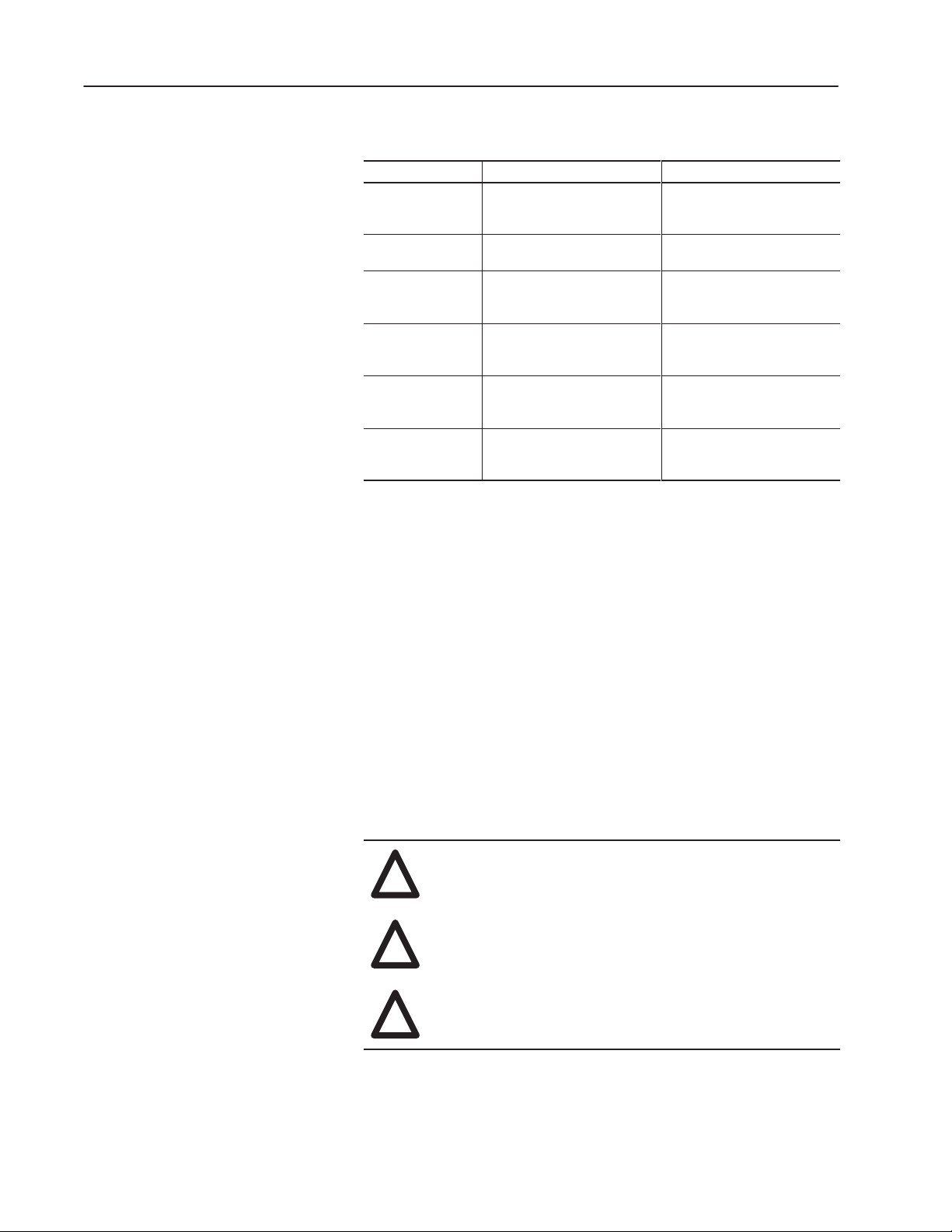
ATTENTION: Electric shock can cause injury or
!
death. Disconnect all power before working on this
product.
ATTENTION: Hazard of injury exists if you are
!
installing the Gasket Kit on a D or E frame. Refer to
the lifting instructions that were included with this kit.
ATTENTION: Drive heatsink surface temperature
!
may be at or near 100C. To avoid burns, do not
contact with the drive heatsink.
Bulletin 1336–5.87 – November, 1997
Page 3

Bulletin 1336 PLUS, 1336 IMPACT, and 1336 FORCE NEMA Type 4/12 Gasket Kit
1–3
Before Installing the
Gasket Kit
The Bulletin 1336 PLUS, 1336 IMPACT, or 1336 FORCE Hardware
User Manual provides general installation requirements and
connection procedures. In addition to those procedures, you should
note the following before installing the Gasket Kit:
• When locating the drive, allow a minimum clearance from other
components of 101.6mm (4.0in) on the top and bottom, and
50.8mm (2.0in) on either side.
• With the heatsink exposed to the ambient air, the drive dissipates
heat as listed under User/Customer Supplied Enclosures. Refer to
the Drive User Manual, Appendix – Specifications/General.
• When mounting the drive, ensure that the heatsink fins are
vertical.
• Refer to your 1336 PLUS, 1336 IMPACT, or 1336 FORCE User
Manual for internal heat dissipation data.
• For all ratings, you must verify that the selected enclosure
dissipates the total BTUs generated within the enclosure without
letting the internal ambient rise above 50° C. Enclosure
mounting must let the heatsink extend outside the enclosure.
• Refer to Figures 1.1 through 1.6 for information on heatsink
protrusion, cutout, and drilling plans.
Bulletin 1336–5.87 – November, 1997
Page 4

1–4
Bulletin 1336 PLUS, 1336 IMPACT, and 1336 FORCE NEMA Type 4/12 Gasket Kit
Installing the Drive Using
the Gasket Kit
To install the gasket, follow these steps:
1. Cut out the heatsink area.
2. Drill the mounting holes. Before drilling the mounting holes you
should make sure that they follow the appropriate drilling pattern
(Figures 1.1 to 1.6) and carefully read the Important on the first
page of this instruction sheet.
3. Clean and file the surface area to remove any burrs or sharp
edges.
4. Use paint to touch up all raw metal edges.
5. Place the gasket, with the gasket paper still intact, around the
cutout area on the inside of the enclosure and align the mounting
holes. The gasket holes are not equally spaced.
6. Peel away the gasket paper.
7. Firmly press the gasket in place with the adhesive towards the
chassis surface aligning mounting holes.
8. Remove the cover, mounting feet, and four side plates from the
drive.
9. Install the drive in the enclosure using the recommended
mounting screws. You should insert the screws through the drive
chassis to the outside of the enclosure.
10.Torque all mounting screws to the value shown in the table below.
Rating Number of Screws
RF2 14 2.9 (26)
RF3 10 2.9 (26)
RF4 8 2.9 (26)
RF5 12 2.9 (26)
RF6 16 2.9 (26)
RF7 26 2.9 (26)
Torque
N*m (in–lbs)
Bulletin 1336–5.87 – November, 1997
Page 5

Bulletin 1336 PLUS, 1336 IMPACT, and 1336 FORCE NEMA Type 4/12 Gasket Kit
Figure1.1
Heat Sink Through-the-Back Mounting – Frames A1, A2, A3
1
210.0
(8.25)
98.0
(3.86)
196.0
(7.72)
1–5
249.7
(9.83)
234.2
(9.2204)
1
78.1
(3.076)
78.2
(3.080)
182.1
(7.17)
220.0
(8.66)
All Dimensions in Millimeters and (Inches)
Cutout
10 Required
4.3 (0.171) Dia. for 10-32 x 12.7 (0.5) Self-Tap – 4.0 (0.159) for 10-32 x 12.7 (0.5) Threaded
Customer-supplied hardware should have thread sealant applied before installation.
Drive
1
Shading indicates approximate size
of drive inside enclosure.
Back of Enclosure
A1 = 50.8 (2.00)
A2 = 71.4 (2.81)
A3 = 98.8 (3.85)
Bulletin 1336–5.87 – November, 1997
Page 6

1–6
Bulletin 1336 PLUS, 1336 IMPACT, and 1336 FORCE NEMA Type 4/12 Gasket Kit
Figure 1.2
Heat Sink Through-the-Back Mounting – Frames A4
1
257.0
80.4
(3.17)
120.7
(4.75)
(10.12)
160.9
(6.33)
241.3
(9.50)
317.0
(12.48)
301.2
(11.86)
1
225.9
(8.89)
150.6
(5.93)
75.3
(2.96)
225.0
(8.86)
285.0
(11.22)
Cutout
All Dimensions in Millimeters and (Inches)
14 Required
4.3 (0.171) Dia. for 10-32 x 12.7 (0.5) Self-Tap – 4.0 (0.159) for 10-32 x 12.7 (0.5) Threaded
Customer-supplied hardware should have thread sealant applied before installation.
Bulletin 1336–5.87 – November, 1997
Drive
1
Shading indicates approximate size
of drive inside enclosure.
Back of Enclosure
90.0 (3.54)
Page 7

Bulletin 1336 PLUS, 1336 IMPACT, and 1336 FORCE NEMA Type 4/12 Gasket Kit
Figure 1.3
Heat Sink Through-the-Back Mounting – Frame B
1
267.2
(10.52)
6.35
(0.25)
257.1
(10.12)
1–7
435.4
(17.14)
1
410.2
(16.15)
308.6
(12.15)
283.2
(11.15)
2.54
(0.10)
127.0
(5.00)
244.4
(9.62)
415.3
(16.35)
Cutout as Viewed
from INSIDE Enclosure
All Dimensions in Millimeters and (Inches)
8 Required
4.3 (0.171) Dia. for 10-32 x 12.7 (0.5) Self-Tap – 4.0 (0.159) for 10-32 x 12.7 (0.5) Threaded
Customer-supplied hardware should have thread sealant applied before installation.
Drive
Back of Enclosure
129.3 (5.09)
1
Shading indicates approximate size
of drive inside enclosure.
Bulletin 1336–5.87 – November, 1997
Page 8

1–8
Bulletin 1336 PLUS, 1336 IMPACT, and 1336 FORCE NEMA Type 4/12 Gasket Kit
Figure 1.4
Heat Sink Through-the-Back Mounting – Frame C
1
303.8
(11.96)
4.8
(0.19)
282.5
(11.12)
660.4
(26.00)
635.0
(25.00)
1
508.0
(20.00)
381.0
(15.00)
254.0
(10.00)
4.8
(0.19)
273.1
(10.75)
Cutout
644.7
(25.38)
1
Shading indicates approximate size
of drive inside enclosure.
127.0
(5.00)
All Dimensions in Millimeters and (Inches)
Drive
12 Required
4.3 (0.171) Dia. for 10-32 x 12.7 (0.5) Self-Tap
4.0 (0.159) for 10-32 x 12.7 (0.5) Threaded
Customer-supplied hardware should have
thread sealant applied before installation.
Back of Enclosure
129.3 (5.09)
Bulletin 1336–5.87 – November, 1997
Page 9

Bulletin 1336 PLUS, 1336 IMPACT, and 1336 FORCE NEMA Type 4/12 Gasket Kit
Figure 1.5
Heat Sink Through-the-Back Mounting – Frame D
Detail
4.6 (0.18)
9.9 (0.39)
356.1
(14.02)
362.2
(14.26)
375.2
(14.77)
1
6.1
(0.24)
1–9
1178.1
(46.38)
1118.6
(44.04)
1
962.7
(37.90)
806.7
(31.76)
650.8
(25.62)
494.5
(19.47)
338.6
(13.33)
26.7
(1.05)
1145.3
(45.09)
Cutout as Viewed
from INSIDE Enclosure
587.0
(23.11)
See Detail
(30.47)
680.5
(26.79)
773.9
867.4
(34.15)
1054.4
(41.51)
(7.19)
26.7
(1.05)
1
Shading indicates approximate size
of drive inside enclosure.
* Minimum dimension allowed – More space will
improve fan effectiveness and heat dissipation.
182.6
All Dimensions in Millimeters
and (Inches)
Drive
Back of Enclosure
84.1 (3.31) *
16 Required
4.3 (0.171) Dia. for 10-32 x 9.7 (0.38) Self-Tap
4.0 (0.159) for 10-32 x 9.7 (0.38) Threaded
Customer-supplied hardware should have
thread sealant applied before installation.
Bulletin 1336–5.87 – November, 1997
Page 10

1–10
Bulletin 1336 PLUS, 1336 IMPACT, and 1336 FORCE NEMA Type 4/12 Gasket Kit
Figure 1.6
Heat Sink Through-the-Back Mounting – Frame E
1
508.0
1422.4
(56.00)
1
1095.8
(43.14)
(20.00)
5.8
(0.23)
1084.1
(42.68)
Cutout
489.0
(19.25)
477.3
(18.79)
127.0
(5.00)
54.1
(2.13)
127.0
(5.00)
75.4
(2.97)
1
Shading indicates approximate size
of drive inside enclosure.
* Minimum dimension allowed – More space will
improve fan effectiveness and heat dissipation.
5.8
(0.23)
All Dimensions in Millimeters and (Inches)
Drive
26 Required
4.3 (0.171) Dia. for 10-32 x 9.7 (0.38) Self-Tap
4.0 (0.159) for 10-32 x 9.7 (0.38) Threaded
Customer-supplied hardware should have
thread sealant applied before installation.
Back of Enclosure
132.33 (5.21) *
Bulletin 1336–5.87 – November, 1997
Page 11

Notes
Bulletin 1336 PLUS, 1336 IMPACT, and 1336 FORCE NEMA Type 4/12 Gasket Kit
1–11
Bulletin 1336–5.87 – November, 1997
Page 12

Allen-Bradley, a Rockwell Automation Business, has been helping its customers improve
productivity and quality for more than 90 years. We design, manufacture and support a broad
range of automation products worldwide. They include logic processors, power and motion
control devices, operator interfaces, sensors and a variety of software. Rockwell is one of the
worlds leading technology companies.
Worldwide representation.
Argentina • Australia • Austria • Bahrain • Belgium • Brazil • Bulgaria • Canada • Chile • China, PRC • Colombia • Costa Rica • Croatia • Cyprus • Czech Republic •
Denmark • Ecuador • Egypt • El Salvador • Finland • France • Germany • Greece • Guatemala • Honduras • Hong Kong • Hungary • Iceland • India • Indonesia •
Ireland • Israel • Italy • Jamaica • Japan • Jordan • Korea • Kuwait • Lebanon • Malaysia • Mexico • Netherlands • New Zealand • Norway • Pakistan • Peru •
Philippines • Poland • Portugal • Puerto Rico • Qatar • Romania • Russia–CIS • Saudi Arabia • Singapore • Slovakia • Slovenia • South Africa, Republic • Spain •
Sweden • Switzerland • Taiwan • Thailand • Turkey • United Arab Emirates • United Kingdom • United States • Uruguay • Venezuela • Yugoslavia
Allen-Bradley Headquarters, 1201 South Second Street, Milwaukee, WI 53204 USA, Tel: (1) 414 382-2000 Fax: (1) 414 382-4444
Bulletin 1336–5.87 – November, 1997
Supersedes August, 1997
1–1
Copyright 1997 Rockwell International Corporation Printed in USA
P/N 74002–109–01(D)
 Loading...