

Page 1

Instructions
1336 PLUS, PLUSII, IMPACT, and FORCE
C-Frame Front End Conversion Kit
About This Publication
This publication will guide you through installation of the C-Frame
Conversion Kit for the following drives:
Drive Kit Catalog Part Number
1336S, F, E or T -BX040
1336S, F, E or T -B040
1336S, F, E or T -B050
1336S, F, E or T -BX060
1336S, F, E or T -C025
1336S, F, E or T -C030
1336S, F, E or T -C040
1336S, F, E or T -C050
1336S, F, E or T -CX060
1336-CONVCF-SP1A
1336-CONVCF-SP1A
1336-CONVCF-SP1A
1336-CONVCF-SP1A
1336-CONVCF-SP2A
1336-CONVCF-SP2A
1336-CONVCF-SP2A
1336-CONVCF-SP2A
1336-CONVCF-SP2A
(1)
(2)
Important:This Front-End Conversion Kit is used to service C-frame
drives that require replacement of 1336-SN-SP1A,
1336-SN-SP1B, or 1336-SN-SP2A Snubber Boards and/or
1336-BR-SP5A or 1336-BR-SP6A Bridge Rectifiers which are
all obsolete.
Important:The Snubber Board in this Conversion Kit: 1336-SN-SP1C
(460V) or 1336-SN-SP2B (575V) and the Bridge Rectifier in
this Conversion Kit:1336-BR-SP10A (460V and575V) arenot
backwards-compatible with the components listed in the above
paragraph.
Each Conversion Kit consists of the following components:
• Complete C-Frame drive, less the components listed below.
• Bus Inductor and bus fuse for either BX060
(1)
or CX060
(2)
.
• 1/4 turn screws (qty 2) for the Snubber Board.
• IGBT shorting devices (qty 2) for the J7 and J8 connectors.
• A label to mount next to the nameplate of the converted drive.
The Conversion Kit does not include the following:
• Main Control Board, mounting plate, or option cards.
• Gate Driver Board.
• Precharge Board and mounting brackets.
• Drive enclosure and mounting hardware, etc.
(1)
The Bus Inductor and bus fuse supplied in the CONVCF-SP1A Kit can be used on all C-frame drives (460V).
(2)
The Bus Inductor and bus fuse supplied in the CONVCF-SP2A Kit can be used on all C-frame drives (575V).
Page 2
2 1336 PLUS, PLUSII, IMPACT, and FORCE C-Frame Front End Conversion Kit
ATTENTION: This drive contains ESD (Electrostatic
!
!
!
Discharge) sensitive parts and assemblies. Static control
precautions are required when installing, testing,
servicing or repairing this assembly. Component
damage may result if ESD control procedures are not
followed. If you are not familiar with static control
procedures, reference publication 8000-4.5.2,
“Guarding Against Electrostatic Damage” or any other
applicable ESD protection handbook.
ATTENTION: To avoida shockhazard, assure that all
powerto thedrive has been removed beforeproceeding.
In addition, verify that the DC bus has discharged by
measuring across the “+DC” and “–DC” terminals of
TB1 with a voltmeter. The voltage should be 0.0VDC.
ATTENTION: Wear a wrist-type grounding strap
when servicing/handling all 1336-family drive printed
circuit boards. Failure to protect drive components
against ESD may damage internal drive components.
Refer to Electrostatics Discharge Precautions at the
beginning of Chapter 3 in the C-Frame Troubleshooting
Guide.
Tools
You need the following tools to disassemble and assemble the drive
• C-frame Troubleshooting Guide 1336 PLUS-6.2, 1336 FORCE-6.2, or
1336 IMPACT-6.2.
• Pliers.
• Phillips screwdriver.
• Standard screwdriver.
• Torque wrench, metered in lb-in. or N-m.
Page 3
1336 PLUS, PLUSII, IMPACT, and FORCE C-Frame Front End Conversion Kit 3
Fastener Torque
Specifications
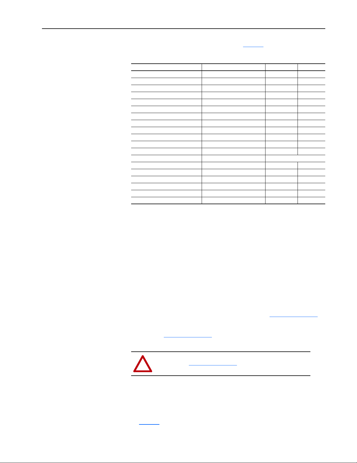
Fastener Torque Specifications are listed in Table A.
Table A Fastener Torque Specifications
Component Fastener Application Torque lb-in. Torque N-m
Main Control Board Mounting Plate 8 – 10 0.9 – 1.1
Gate Driver Board Mounting Plate 8 – 10 0.9 – 1.1
Precharge Board Mounting Plate 8 – 10 0.9 – 1.1
Bus Capacitor Bank Bank to chassis 25 – 31 2.8 – 3.5
DC Bus Inductor Wires to bus bars 25 – 31 2.8 – 3.5
DC Bus Inductor TB1 mounting plate to chassis 25 – 31 2.8 – 3.5
Snubber Board Bus bars to capacitor bank 25 – 31 2.8 – 3.5
Snubber Board Board to SCR1 25 – 31 2.8 – 3.5
Snubber Board Board to PM1 – PM3 30 – 39 3.4 – 4.4
Power Modules PM1 – PM3 Module to heat sink 25 – 31 2.8 – 3.5
Input Rectifier Rectifier to heat sink 25 – 31 2.8 – 3.5
Bus Fuse F1 Fuse to chassis 200 – 220 22.6 – 24.8
Thermistor Thermistor to heat sink Hand tighten only
TB1 Wires to terminals 25 – 31 2.8 – 3.5
TB2 Wires to terminals 8 0.9
TB3 Wires to terminals 8 0.9
Ground Sense CT Bracket to chassis 25 – 31 2.8 – 3.5
Ground Sense CT Positive bus bar junction 25 – 31 2.8 – 3.5
Ground Sense CT Bus bars to capacitor bank 25 – 31 2.8 – 3.5
Instructions
1. Back-up the programming of the drive being converted before
proceeding:
– Store the programming of the drive in the HIM (if applicable to your
HIM) or
– Use Drive Tools, Drive Explorer, or Drive Explorer Light to back-up
the programming of the drive.
2. Remove andlock out the line power from the existing C-frame drive that
will be converted.
3. For disassembly instructions, refer to Chapter 3 in the Troubleshooting
Guide. The 1336-CONVCF-SPxA Kit is shown in
Figure 1 on page 5.
4. An illustration of the CONVCF Kit with numbered cables and wires is
shown in
Figure 2 on page 6. The cables have the destination connector
number on them.
ATTENTION: Make sure the two shorting devices
!
shown in
connecting into J7 and J8 of the Gate Driver Board.
Figure 3 on page 6 are removed before
5. For assembly instructions refer to Chapter 3 in the Troubleshooting
Guide.
6. Re-connect the power and control wiring. Torque specs are listed in
Table A.
Page 4

4 1336 PLUS, PLUSII, IMPACT, and FORCE C-Frame Front End Conversion Kit
7. Install the CONVCFlabel on the Main ControlBoard Mounting Plate as
shown in
Figure 1 on page 5. This indicates the conversion has been
done on your drive.
8. Refer to the Plus/PlusII/Impact/Force User Manual for Start-Up
instructions.
9. Reinstall the Main Control Board, Gate Driver Board and Precharge
Board from the old drive. Refer to
of the converted drive will be necessary.
10.Re-install the shorting devices into the same cable connectors on the old
drive. This will prevent any damage to the IGBT’s from static electricity
while handling and shipping the old drive.
11.Return the old drive core to Allen-Bradley if the drive is in warranty.
Figure 1 on page 5. No programming
Page 5

1336 PLUS, PLUSII, IMPACT, and FORCE C-Frame Front End Conversion Kit 5
Figure 1 Drive Components for 1336-CONVCF Kit
Heat Sink and
Fan Assembly
New Label
Factory Installed
1336-CONVCF-SPxA
Load Sharing
Resistor
Bus Fuse
Snubber Board
460V has 1
575V has 2
and LEMs
These components
are included in the
1336-CONVCF-SPxA Kit.
End user will remove all of these components from the existing
drive and install on the 1336-CONVCF-SPxA Kit.
Remove the shorting devices before attaching
cables to the Gate Driver Board. Refer to Figure 3.
Ground Sense
CT Connector
Snubber Board
Connector
ATTENTION:
Power Module
Connectors
SCR
Connector
Gate Driver Board
Ribbon Cable
Connector
Thermistor
Connector
Bus Capacitor
Bank
Bus Inductor
(Behind Ground
Sense CT)
Bus Cap
Connectors
Snubber Board/SCR
Connector
Add New Label Here,
Customer Installed
1336-CONVCF-SPxA
Existing Label
Nameplate
Factory Installed
Main
Control
Board
Interface Board
Connectors
HIM
Connector
(Optional)
Control
Interface
Board
ab1006a
Page 6

6 1336 PLUS, PLUSII, IMPACT, and FORCE C-Frame Front End Conversion Kit
Figure 2 1336-CONVCF-SPxA Conversion Kit.
J6
J2
J10
J7
J15
J8
J4
J1
J2
ab1008a
Figure 3 1336-CONVCF-SPxA Conversion Kit showing the shorting devices.
J7
Shorting
Devices
J8
ab1009a
Page 7

Notes:
1336 PLUS, PLUSII, IMPACT, and FORCE C-Frame Front End Conversion Kit 7
Page 8

Netscape Navigator is a registered trademark of Netscape Communications Corporation
IBM is a registered trademark of International Business Machines Corporation
Microsoft, MS-DOS and Windows are registered trademarks of Microsoft Corporation
Publication 1336 FREST-5.15 Ð May, 2001 P/N 196517-P01
Copyright © 2001 Rockwell Automation. All rights reserved. Printed in USA.
 Loading...