

Page 1
Installation Instructions
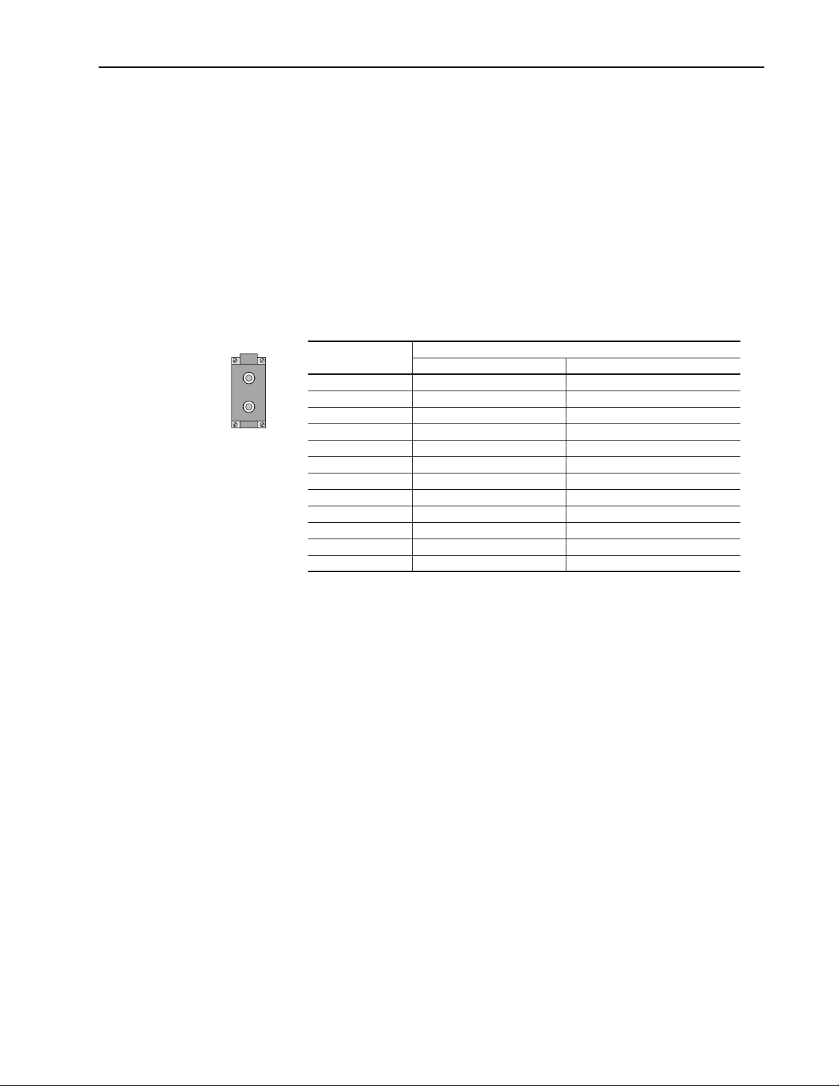
Typical Snubber
Board(s) Location
Inverter Bay Converter Bay
Multipulse Bridge Assembly Parts Kits
These instructions cover front end component replacements on 1336 PLUS
II drives and 1336 IMPACT H frame drives with Multipulse bridge
assemblies.
Description Page
Snubber Board Replacement Kit 1
Converter Diode Replacement Kit 3
Converter Fan Replacement Kit 6
Converter Thermal Switch Replacement Kit 8
Spare Parts 10
Replacement Parts 12
Snubber Board Replacement Kit
Where This Kit Is Used
Snubber Board Replacement Kit (Part Numbers 304470 (AC), 304469,
304468 (DC)) - You can use this kit to replace the snubber boards that are
located on the side of the AC Diode bridge heatsink assembly.
Table 1. Snubber Board Part Numbers
Replacement Kit Number Vendor No.
1336 - SN-SP7B 20849
1336 - SN-SP8B 21032
1336 -SN-SP9B 13960
What This Kit Contains
This kit contains snubber board(s) and these instructions. Note: Number of
snubber boards varies according to kit number.
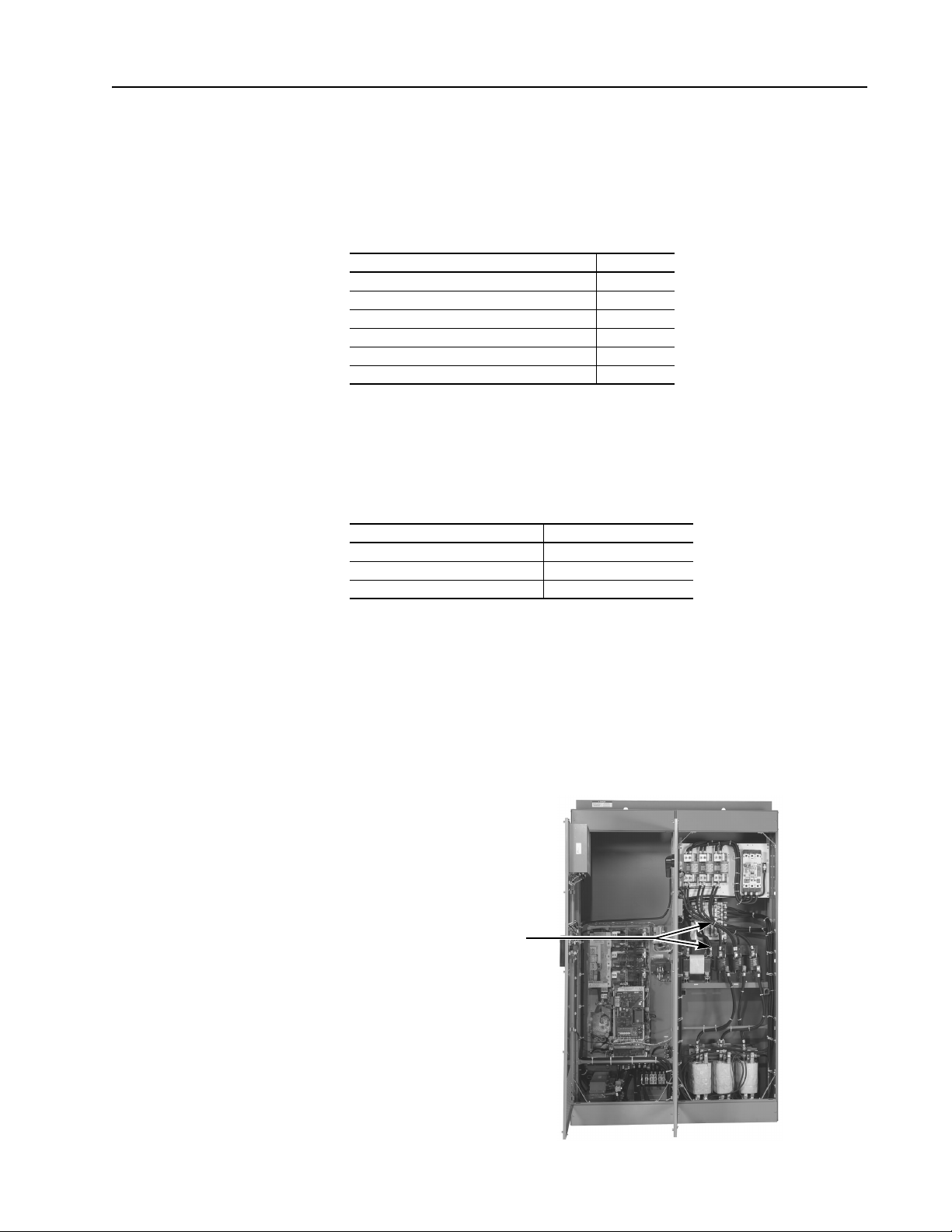
Locating the Snubber Board(s)
The snubber boards are located on the side of the bridge heatsink in the
converter bay of your drive. The location of the converter bay will vary from
system to system.
Page 2
2 Multipulse Bridge Assembly Parts Kits
!
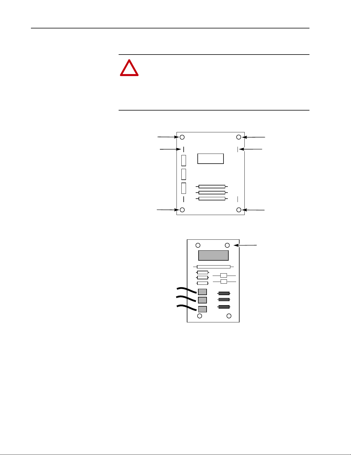
06
16
- Lead
Standoff Hole
Standoff Hole
Standoff Hole
Standoff Hole
+ Lead
DC Snubber Board Front View
AC Snubber Board Front View
Power
Leads
Standoff Hole
(4 Places)
81
82
83
To p
Replacing the Snubber Board(s)
ATTENTION: Disconnect and lock out power from the system
before disassembling the bridge. Failure to disconnect power
may result in death or serious injury. Verify bus voltage by
measuring the voltage between +DC and –DC on terminal block
TB1 located at the bottom of the 1336 Drive in the inverter bay.
Do not attempt to service the drive until the bus voltage has
discharged to zero volts.
1. Remove and tag the leads at the + (06) and – (16) stab-on connections on
2. Snap the old board up off the four plastic standoffs and remove.
3. Orient the new board with the stab-on connectors 06 and 16 at the top
4. Reconnect the leads.
the DC snubber board. Remove the leads at stab-on connectors 81, 82
and 83 on AC snubber boards.
(DC boards) or stab-on connectors 81, 82 and 83 in the lower left (AC
boards) and snap into place on the plastic standoffs.
Page 3
Multipulse Bridge Assembly Parts Kits 3
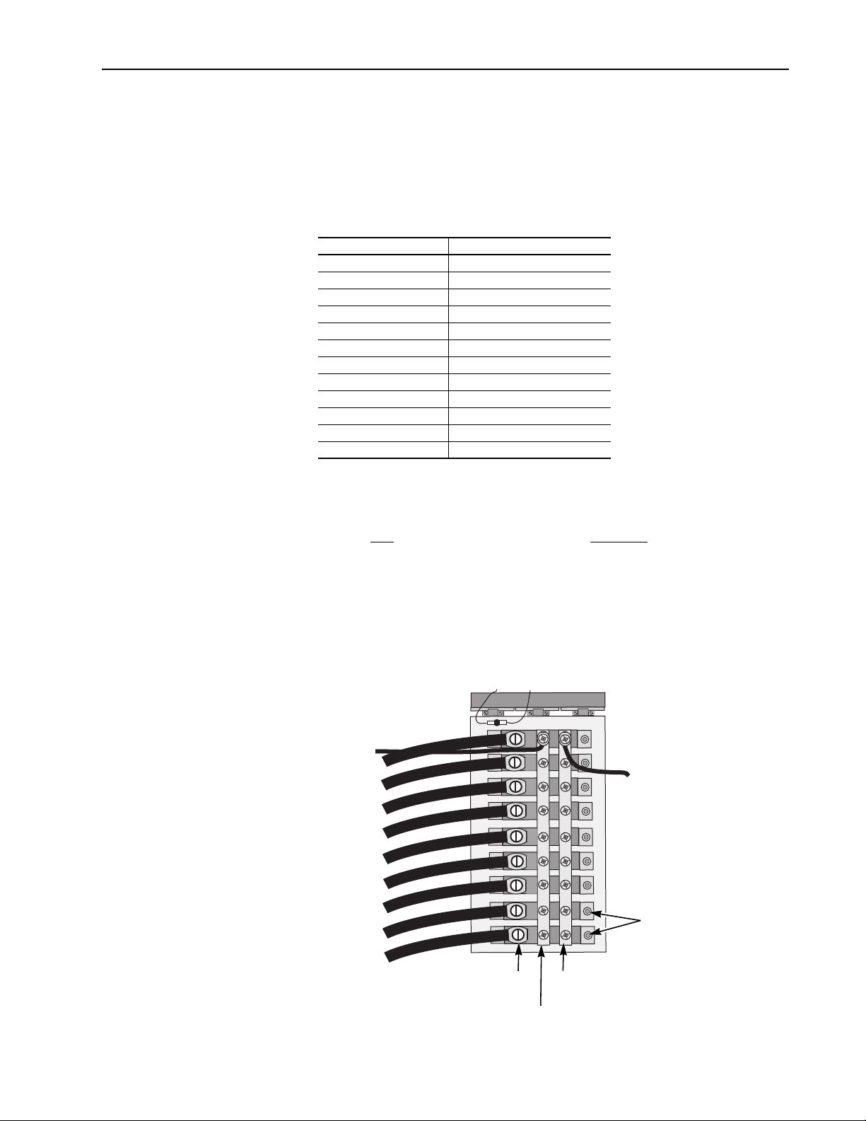
AK
Terminal
K
Terminal
A
Terminal
Converter Diodes
Converter Diode Replacement Kit
Where This Kit Is Used
You can use this kit to replace any of the converter diodes that are located in
the converter bay of your 1336 PLUS II Multipulse or H-Frame 1336
IMPACT drive.
Diodes covered by these instructions are listed in the following table:
Table 2. Converter Diode Part Numbers
Replacement Kit No. Vendor Component Part No.
1336-BD-SP1A DD89N16K
1336-BD-SP2A DD104N16K
1336-BD-SP3A DD151N16K
1336-BD-SP4A DD260N16K
1336-BD-SP5A DD350N16K
1336-BD-SP6A DD600N18K
1336-BD-SP7A DZ1070N18K
1336-BD-SP8A DD2228N16T
1336-BD-SP9A ND89N16K
1336-BD-SP10A ND171N16K
1336-BD-SP11A ND260N16K
1336-BD-SP12A DZ600N16K
What This Kit Contains
This kit contains a replacement converter diode and these instructions. This
kit does Not
contain the thermal compound Required to mount a new diode.
Locating the Converter Diodes
The converter diodes are located on the Multipulse bridge heatsink
assembly in the converter bay of your drive. A typical heatsink assembly is
shown in the following illustration. Converter diode locations may vary on
some models.
Fan
Page 4
4 Multipulse Bridge Assembly Parts Kits
!
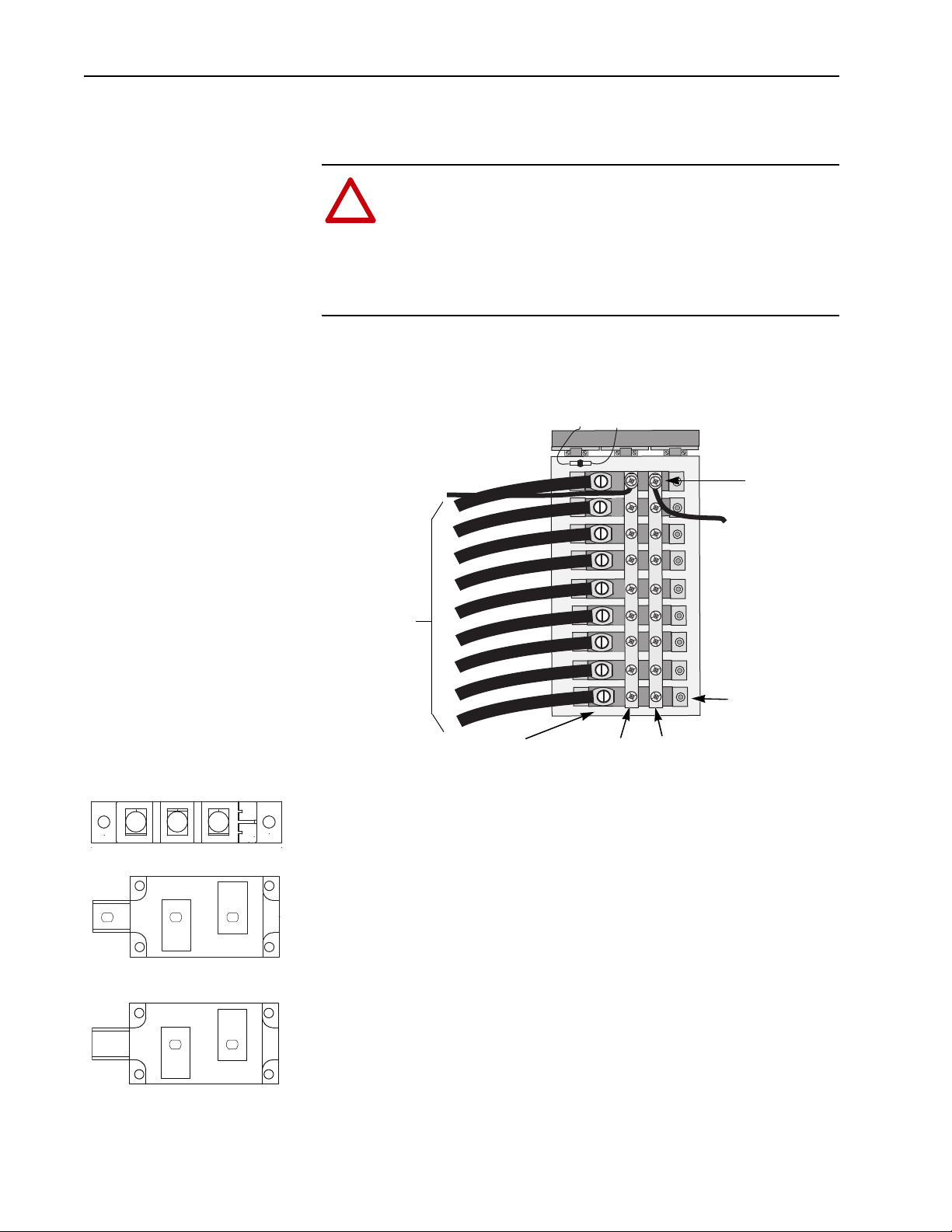
Converter
Diode Mounting
Screw
A
Bus Bar
K
Bus Bar
“AK” Input Terminal
+/- Power Leads
From Snubber
Board
From
Transformer
From
Snubber
Board
AK
K
A
DD350N
1
2
3
4
1
AK
2
K
A
DD104N
K
A
ND260N
1
2
3
4
Replacing the Converter Diode(s)
To replace the converter diode(s), follow these steps:
ATTENTION: Disconnect and lock out power from the system
before disassembling the bridge. Failure to disconnect power
may result in death or serious injury. Verify bus voltage by
measuring the voltage between +DC and –DC on terminal block
TB1 located at the bottom of the 1336 Drive in the Inverter Bay.
Do not attempt to service the drive until the bus voltage has
discharged to zero volts.
1. Remove the power leads to + and -bus bars at the connection points at
the top of the bus bars.
2. Remove the + / - bus bars that are over the converter diode by removing
all the screws at the “A” and “K” mounting points on each diode.
Fan
3. Remove the “AK” input terminal from the converter diode you will be
replacing. Tag leads if you are replacing more than one diode.
4. Remove the mounting screws from the converter diode. The diode will
have two or four mounting screws depending on the model. For
example: the DD104N shown in the accompanying illustration has two
mounting screws, while the DD350N has four.
5. Remove the converter diode.
A. Remove all old heat transfer compound from the heatsink mounting
surface using a tool such as a rubber spatula that will not mar the
heatsink surface. Remove any remaining residue with a soft cloth and
a cleaning fluid such as Essex Cleaning Fluid (Brownell OS-3) by
Dow Corning Co.
B. Use a non-marring cleaning pad such as a Scotchbrite by 3M™ to
remove any oxidation from the heatsink mounting surface and the
face of the diode. DO NOT use steel wool or sandpaper!
C. Follow oxidation removal with a final cleaning with cleaning fluid.
Page 5
Multipulse Bridge Assembly Parts Kits 5
14
32
Important: Thermal Compound must be applied immediately to both
surfaces to prevent oxidation from reoccurring.
6. Apply a thin, even coat of Thermal Compound (not supplied) to the new
diode and the mounting surface. Dow Corning 340 is the recommended
Thermal Compound.
7. Position the new converter diode being careful to match the holes for
the screws.
8. Tighten the screws (2 or 4 depending on model) in the sequence shown
in the illustration, to the Mounting Screw torques in Table 3.
Table 3. Diode Torque Requirements
TORQUE REQUIREMENT
Vendor P/N
DD89N16K 35 in. lb., 4 N–m (+/-15%) 35 in. lb., 4 N–m (+ 5%/-10%)
DD104N16K 35 in. lb., 4 N–m (+/-15%) 35 in. lb., 4 N–m (+ 5%/-10%)
DD151N16K 53 in. lb., 6 N–m (+/-15%) 53 in. lb., 6 N–m (+5%/-10%)
DD260N16K 44 in. lb., 5 N–m (+/-15%) 106 in. lb., 12 N–m (+5%/-10%)
DD350N16K 44 in. lb., 5 N–m (+/-15%) 106 in. lb., 12 N–m (+5%/-10%)
DD600N18K 53 in. lb., 6 N–m (+/-15%) 106 in. lb., 12 N–m (+5%/-10%)
DZ1070N18K 53 in. lb., 6 N–m (+/-15%) 159 in. lb., 18 N–m (+5%/-10%)
DD2228N16T 159 in. lb, 18 N–m (+/-15%) 159 in. lb., 18 N–m (+5%/-10%)
ND89N16K 35 in. lb., 4 N–m (+/-15%) 35 in. lb., 4 N–m (+/-15%)
ND17N16K 35 in. lb., 4 N–m (+/-15%) 35 in. lb., 4 N–m (+/-15%)
ND260N16K 44 in. lb., 5 N–m (+/-15%) 106 in. lb., 12 N–m (+/-15%)
DZ600N16K 44 in. lb., 5 N–m (+/-10%) 106 in. lb., 12 N–m (+/-15%)
Mounting Screw Torque Terminal Connection Torque
9. Bolt down the + and - bus bars, tightening the screws to the Terminal
Connection torque values shown in the previous table.
10. Reattach the power leads at the top of each bus bar and torque the
mounting screws to the value shown under Terminal Connection in the
previous table.
11. Attach the “AK” terminal to the new diode and torque to the specified
Terminal Connection value shown in the Table 3.
Page 6

6 Multipulse Bridge Assembly Parts Kits
Typical Fan
Location
Converter Fan Replacement Kit
Where This Kit Is Used
Converter Fan Replacement (Catalog Number 1336-FAN-SP9A) -You
can use this kit to replace any of the fans that are located on the bridge
heatsink in the converter bay of your1336 PLUS II Multipulse or 1336
IMPACT H-Frame drive. The number of fans varies by model.
Table 4. Fan Part Numbers
Replacement Kit # Vendor #
1336 - FAN - SP9A 21087
What This Kit Contains
This kit contains a replacement fan and these instructions.
Locating the Fan(s)
The fans are located on the multi-pulse bridge heatsink in the converter bay
of your drive. Fans are oriented to draw air up through the heatsink
assembly.
Page 7

Multipulse Bridge Assembly Parts Kits 7
!
Fan Spacer
Air Flow
Fan Wires
Replacing the Fan(s)
To replace the fan(s), follow these steps:
ATTENTION: Disconnect and lock out power from the system
before disassembling the drive. Failure to disconnect power may
result in death or serious injury. Verify bus voltage by measuring
the voltage between +DC and –DC on terminal block TB1 which
is located at the bottom of the 1336 Drive in the Inverter Bay. Do
not attempt to service the drive until the bus voltage has
discharged to zero volts.
1. Remove the red 115V power supply and white neutral wires from the
stab-on connectors on the fan.
Fan
2. Using a thin, standard screwdriver, remove the screws and lockwashers
that secure the fan.
3. Remove the fan and fan spacer.
4. Put the new fan in place, making sure that you align the holes in the
bridge with the holes in the four corners of the fan and fan spacer.
Important:Make sure that the arrows on the fan are pointing towards
the top of the cabinet.
5. Start the screws and lockwashers in the four corners.
6. Tighten the screws to 1.36 N–m (12 lbs.–in.).
7. Attach the red power supply and white neutral wires to the stab-on
connectors on the fan.
Page 8

8 Multipulse Bridge Assembly Parts Kits
Fan
Remote
Thermal
Switch(es)
Location
Internal Mount
Thermal
Switch(es)
Location
Converter Thermal Switch Replacement Kit
Where This Kit Is Used
Converter Thermal Switch Replacement (Catalog Number
1336-TR-SP8A) - You can use this kit to replace the thermal switch(es) that
are located on the multipulse bridge assembly in the converter bay of your
1336 PLUS II Multipulse or H-Frame IMPACT drive.
Table 5. Thermal Switch Part Numbers
Replacement Kit # Vendor #
1336 - TR- SP8A 16283
What This Kit Contains
This kit contains a replacement thermal switch and these instructions.
Locating the Thermal Switches
The thermal switches are mounted on the bridge heatsink located in the
converter bay of your drive.
Important: On some drive models the thermal switch may be located
remotely at the top of the heatsink above the bus bars as shown in the
following illustration. In cases where the thermal switch is mounted
remotely it will not be necessary to remove the “AK” input terminals or bus
bars for access to the switch.
Page 9

Multipulse Bridge Assembly Parts Kits 9
!
“AK”
Bus Bar
Thermal
Switch
600 HP and higher Thermal Bridge shown
Location
Thermal
Switch
Replacing the Thermal Switch(es)
To replace the thermal switch(es), follow these steps:
ATTENTION: Disconnect and lock out power from the system
before disassembling the drive. Failure to disconnect power may
result in death or serious injury. Verify bus voltage by measuring
the voltage between +DC and –DC on terminal block TB1 which
is located at the bottom of the 1336 Drive located in the Inverter
Bay of the cabinet. Do not attempt to service the drive until the
bus voltage has discharged to zero volts.
Important: If your thermal switch is NOT located under a bus bar, it will
not be necessary to perform steps 1, 2, 7 or 9.
1. Remove the flex bus or wire connected to the “AK” input terminal bus
bar or diode that is located over the thermal switch you need to replace.
2. If your unit is equipped with a bus bar, remove it.
3. Remove the red power wires from the thermal switch.
4. Remove the thermal switch.
5. Thread in the new thermal switch by hand until it is snug.
6. Tighten the screw on the thermal switch to 1.81 N–m (16 lbs.–in.).
7. Bolt the “AK” input terminal bus bar or wire terminal to the diode and
see Table 8 for kit reference numbers.
Page 10

10 Multipulse Bridge Assembly Parts Kits
Spare Parts
To determine spare parts for your Bridge Assembly, follow these steps:
A. Determine Drive Size (HP) using Table 6 for CT or Table 7 for VT and
then the type of multi-pulse transformer used in the drive package.
B. Find drive size and move to the right until you are under the column
which describes the transformer. That number is the bridge assembly
number (Table 8).
Example: Bridge 304246 =1336-BD-SP5A diode kit#
1336-SN-SP9B snubber board kit #
1336-FAN-SP9A fan kit
1336-TR-SP8A thermo switch kit
Table 6. CT Bridge Assemblies
1336 Constant Torque Used with 12P ISO. XFMR Used with 12P Auto XFMR Used with 18P ISO. XFMR Used with 18P Auto XFMR
Drive Size (HP)
AB Part Numbers Bridge # Bridge # Bridge # Bridge #
BX040C 301746 304976 301749 301743
B050C 301746 304976 301750 301743
BX060C 301746 304976 301750 301743
B060C 301746 304976 301750 301743
B075C 301746 304976 304247 301743
B100C 304250 304976 304247 301744
B125C 301747 304976 301751 301744
BX150C 301747 304976 301751 301744
B150C 301747 304976 304248 301744
B200C 301747 304652 304249 301745
B250C 304245 304652 301752 301745
BP250C 304245 304652 301752 301745
BP300C 304245 304652 301752 301745
BP350C 304246 304652 301753 301745
BP400C 304248 304652 301753 304348
BP450C 304248 304977 301235 304348
B300C 304245 304652 301752 301745
B350C 304246 304652 301753 301745
B400C 301748 304652 301753 304348
B450C 301748 304977 301753 304348
B500C 301233 304977 301235 304348
B600C 301233 304977 301236 304348
B700C 301234 304978 301236 301231
B800C 301234 304978 301236 301231
Page 11

Multipulse Bridge Assembly Parts Kits 11
Table 7. VT Bridge Assemblies
1336 Variable Torque Used with 12P ISO. XFMR Used with 12P Auto XFMR Used with 18P ISO. XFMR Used with 18P Auto XFMR
Drive Size (HP)
AB Part Numbers Bridge # Bridge# Bridge # Bridge #
BX040V 301746 304976 301749 301743
B040V 301746 304976 301750 301743
BX060V 301746 304976 301750 301743
B060V 301746 304976 304247 301743
B075V 301746 304976 304247 301744
B100V 304250 304976 304247 301744
B125V 301747 304976 301751 301744
B150V 301747 304976 304249 301744
B200V 304245 304652 304249 301745
B250V 304245 304652 301752 301745
BP250V 304245 304652 301752 301745
BP300V 304246 304652 301753 301745
BP350V 301748 304652 301753 301745
BP400V 301748 304977 301235 304348
BX250V 304245 304652 301752 301745
B300V 304246 304652 301753 301745
B350V 301748 304652 301753 304348
B400V 301748 304977 301235 304348
B450V 301233 304977 301235 304348
B500V 301233 304977 301236 304348
B700V 301234 304978 301236 301231
B800V 301234 304978 301236 301231
Page 12

12 Multipulse Bridge Assembly Parts Kits
Replacement Parts
Bridge # Diode Snubber Fan Thermal Switch
301229 1336-BD-SP5A 1336-SN-SP8B 1336-FAN-SP9A 1336-TR-SP8A
301230 1336-BD-SP6A 1336-SN-SP8B 1336-FAN-SP9A 1336-TR-SP8A
301231 1336-BD-SP5A 1336-SN-SP8B 1336-FAN-SP9A 1336-TR-SP8A
301232 1336-BD-SP5A 1336-SN-SP8B 1336-FAN-SP9A 1336-TR-SP8A
301233 1336-BD-SP6A 1336-SN-SP9B 1336-FAN-SP9A 1336-TR-SP8A
301234 1336-BD-SP7A 1336-SN-SP9B 1336-FAN-SP9A 1336-TR-SP8A
301235 1336-BD-SP6A 1336-SN-SP9B 1336-FAN-SP9A 1336-TR-SP8A
301236 1336-BD-SP7A 1336-SN-SP9B 1336-FAN-SP9A 1336-TR-SP8A
301738 1336-BD-SP1A 1336-SN-SP7B N/A 1336-TR-SP8A
301739 1336-BD-SP3A 1336-SN-SP7B N/A 1336-TR-SP8A
301740 1336-BD-SP2A 1336-SN-SP8B 1336-FAN-SP9A 1336-TR-SP8A
301741 1336-BD-SP3A 1336-SN-SP8B 1336-FAN-SP9A 1336-TR-SP8A
301742 1336-BD-SP4A 1336-SN-SP8B 1336-FAN-SP9A 1336-TR-SP8A
301743 1336-BD-SP1A 1336-SN-SP7B N/A 1336-TR-SP8A
301744 1336-BD-SP1A 1336-SN-SP8B 1336-FAN-SP9A 1336-TR-SP8A
301745 1336-BD-SP3A 1336-SN-SP8B 1336-FAN-SP9A 1336-TR-SP8A
301746 1336-BD-SP2A 1336-SN-SP9B 1336-FAN-SP9A 1336-TR-SP8A
301747 1336-BD-SP4A 1336-SN-SP9B 1336-FAN-SP9A 1336-TR-SP8A
301748 1336-BD-SP6A 1336-SN-SP9B 1336-FAN-SP9A 1336-TR-SP8A
301749 1336-BD-SP3A 1336-SN-SP9B N/A 1336-TR-SP8A
301750 1336-BD-SP2A 1336-SN-SP9B 1336-FAN-SP9A 1336-TR-SP8A
301751 1336-BD-SP4A 1336-SN-SP9B 1336-FAN-SP9A 1336-TR-SP8A
301752 1336-BD-SP5A 1336-SN-SP9B 1336-FAN-SP9A 1336-TR-SP8A
301753 1336-BD-SP6A 1336-SN-SP9B 1336-FAN-SP9A 1336-TR-SP8A
303680 1336-BD-SP8A 1336-SN-SP9B 1336-FAN-SP9A 1336-TR-SP8A
304243 1336-BD-SP5A 1336-SN-SP8B 1336-FAN-SP9A 1336-TR-SP8A
304244 1336-BD-SP6A 1336-SN-SP8B 1336-FAN-SP9A 1336-TR-SP8A
304245 1336-BD-SP5A 1336-SN-SP9B 1336-FAN-SP9A 1336-TR-SP8A
304246 1336-BD-SP5A 1336-SN-SP9B 1336-FAN-SP9A 1336-TR-SP8A
304247 1336-BD-SP3A 1336-SN-SP9B 1336-FAN-SP9A 1336-TR-SP8A
304248 1336-BD-SP5A 1336-SN-SP9B 1336-FAN-SP9A 1336-TR-SP8A
304249 1336-BD-SP5A 1336-SN-SP9B 1336-FAN-SP9A 1336-TR-SP8A
304250 1336-BD-SP3A 1336-SN-SP9B 1336-FAN-SP9A 1336-TR-SP8A
304348 1336-BD-SP5A 1336-SN-SP8B 1336-FAN-SP9A 1336-TR-SP8A
304742 1336-BD-SP5A 1336-SN-SP8B 1336-FAN-SP9A 1336-TR-SP8A
304976 1336-BD-SP9A 1336-SN-SP7B 1336-FAN-SP9A 1336-TR-SP8A
304652 1336-BD-SP10A 1336-SN-SP8B 1336-FAN-SP9A 1336-TR-SP8A
304977 1336-BD-SP11A 1336-SN-SP8B 1336-FAN-SP9A 1336-TR-SP8A
304978 1336-BD-SP12A 1336-SN-SP8B 1336-FAN-SP9A 1336-TR-SP8A
To order replacement kits:
A. Find the bridge part number on the actual order related schematics or the
Bridge Assembly data nameplate.
B. Reference that number to this page for replacement kit numbers.
Table 8. Bridge Parts List
Note: All kits are qty (1) pcs.
Page 13

Notes:
Multipulse Bridge Assembly Parts Kits 13
Page 14

Rockwell Automation Support
Rockwell Otomasyon Ticaret A.Ş., Kar Plaza İş Merkezi E Blok Kat:6 34752 İçerenköy, İstanbul, Tel: +90 (216) 5698400
Rockwell Automation provides technical information on the Web to assist you in using its products.
At http://www.rockwellautomation.com/support
sample code and links to software service packs, and a MySupport feature that you can customize to make the best
use of these tools. You can also visit our Knowledgebase at http://www.rockwellautomation.com/knowledgebase
for FAQs, technical information, support chat and forums, software updates, and to sign up for product notification
updates.
, you can find technical manuals, technical and application notes,
For an additional level of technical phone support for installation, configuration, and troubleshooting, we offer
TechConnect
representative, or visit http://www.rockwellautomation.com/support/
SM
support programs. For more information, contact your local distributor or Rockwell Automation
.
Installation Assistance
If you experience a problem within the first 24 hours of installation, review the information that is contained in this
manual. You can contact Customer Support for initial help in getting your product up and running.
United States or Canada 1.440.646.3434
Outside United States or Canada Use the Worl dwide Loca tor
Rockwell Automation representative.
at http://www.rockwellautomation.com/rockwellautomation/support/overview.page, or contact your local
New Product Satisfaction Return
Rockwell Automation tests all of its products to help ensure that they are fully operational when shipped from the
manufacturing facility. However, if your product is not functioning and needs to be returned, follow these
procedures.
United States Contac t your distributor. You must provide a Customer Support case number (call the phone number above to obtain one) to your
Outside United States Please contact your local Rockwell Automation representative for the return procedure.
distributor to complete the return process.
Documentation Feedback
Your comments will help us serve your documentation needs better. If you have any suggestions on how to improve
this document, complete this form, publication RA-DU002
, available at http://www.rockwellautomation.com/
literature/.
Publication 1336-5.91 - May 2013 PN-206339
Supersedes Publication 1336-5.91 - March 2002 Copyright © 2013 Rockwell Auto mation, Inc. All rights reserved. Pr inted in the U.S.A.
 Loading...