

Page 1
Instructions
1336 PLUS II AC Drive
Main Control Board Replacement
Frames A - G
This publication will guide you through replacement of the Main Control
Board on 1336 PLUS II Adjustable Frequency AC Drives.
ATTENTION: This drive contains ESD (Electrostatic Discharge)
sensitive parts and assemblies. Static control precautions are re-
!
quired when installing, testing, servicing orrepairingthisassembly.
Component damage may result if ESD control procedures are not
followed. If you are not familiar with static control procedures,
reference publication 8000-4.5.2, “Guarding Against Electrostatic
Damage” or any other applicable ESD protection handbook.
!
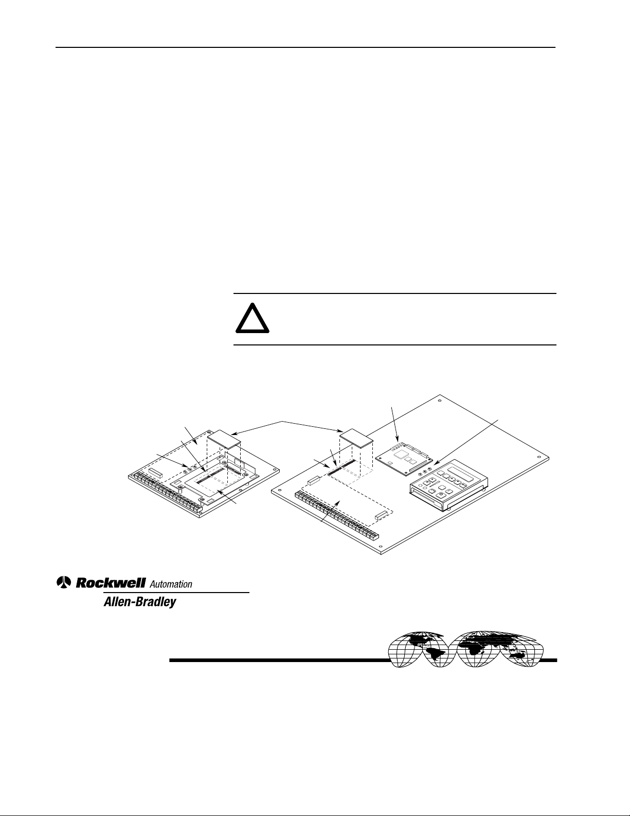
Replacement Procedure Important:
Refer to the figure on page 2 for component locations.
1. Remove and lock-out all incoming power to the drive.
2. Remove/open front cover or remove entire enclosure (on smaller drives)
as required for adequate access.
3. If a HIM (or other snap-in module) is installed, remove it by carefully
squeezing the locking tabs in and pulling out.
4. If a Communications Option (1336-GM1, etc.) is installed in the Adapter
6 location, remove it and transfer it to the new Main Control Board.
5. If a Control Interface Board (L option) is installed, carefully remove the
board by loosening the 2 captive screws. Position the board and attached
wires off to the side of the chassis.
6. If a Control Interface Board is not present, transfer the jumpers at pins 3
& 4 and 17 & 18 of J2 to the same location on the new Main Control
Board.
7. Remove the screws securing the HIM cradle. Remove the cradle.
8. If an Analog Interface Board (LA1, LA2, etc.) is installed in Slot A or B,
note placement and carefully remove the board by releasing standoffs and
lifting straight out. Transfer this board (and standoffs, if needed) to the
same slot on the new board. Repeat if a second board is present.
ATTENTION: To avoid a shock hazard, assure that all power to
the drive has been removed before proceeding with the following
procedure. In addition, verify that the DC bus has discharged by
measuring across the “+DC” and “–DC” terminals of TB1 with a
voltmeter. The voltage should be 0.0VDC.
If parameters were not previously uploaded to a HIM with Upload/
Download Capability, it is recommended that they be uploaded
now, if possible. This will allow downloading after the new board
has been installed, thus preventing complete re-programming.
Page 2
2 1336 PLUS II AC Drive Main Control Board Replacement
9. If Slot A and/or Slot B were not occupied by an option board, jumpers
will be present at J9/J10. Locate these jumpers and note placement.
Transfer the jumpers to the same location on the new Main Control Board.
10. Locate jumpers J8, J11 and J13. Note jumper placement – then transfer
jumpers to the same location on the new board.
11. Label and remove any remaining cables/wires from the board.
12. Remove the screws securing the Main Control Board. Remove the board
and set aside. On B-G Frame drives, the board must be removed from the
mounting plate.
13. Install the new Main Control Board – re-assemble components in reverse
order. Verify that option boards and jumpers are correctly inserted (see the
1336 PLUS II User Manual for details).
Important:
When replacing connectors, it is essential that correct
alignment is verified. Particular attention should be paid to
ribbon cable connectors. Misalignment of connectors could
result in damage to the drive.
ATTENTION: Replace any guards previously removed before applying power to the drive. Failure to replace guards may result in
!
death or serious injury.
Control Interface Option
J9, J10
J8, J11, J13
Frames A1 - A4
14. Apply drive power – if a fault occurs, “Reset Defaults.” Download
parameters (if previously uploaded) from the HIM.
Internal Communication
SLOT B
86
ANALOG I/O
J9
SLOT A
ANALOG I/O
7531
(Adapter 6)
ESC
SEL
JOG
J8, J11, J13
Frames B - G
Analog Option Board
(Slot A)
Slot B
J9, J10
J9
SLOT A
ANALOG I/O
8642
7531
J10
SLOT B
ANALOG I/O
8642
7531
J10
8642
7531
Slot B
Control Interface Option
Rockwell Automation helps its customers receive a superior return on their investment by bringing
together leading brands in industrial automation, creating a broad spectrum of easy-to-integrate
products. These are supported by local technical resources available worldwide, a global network
of system solutions providers, and the advanced technology resources of Rockwell.
Worldwide representation.
Argentina • Australia • Austria • Bahrain • Belgium • Bolivia • Brazil • Bulgaria • Canada • Chile • China, People’s Republic of • Colombia • Costa Rica • Croatia • Cyprus
Czech Republic • Denmark • Dominican Republic • Ecuador • Egypt • El Salvador • Finland • France • Germany • Ghana • Greece • Guatemala • Honduras • Hong Kong
Hungary • Iceland • India • Indonesia • Iran • Ireland • Israel • Italy • Jamaica • Japan • Jordan • Korea • Kuwait • Lebanon • Macau • Malaysia • Malta • Mexico
Morocco • The Netherlands • New Zealand • Nigeria • Norway • Oman • Pakistan • Panama • Peru • Philippines • Poland • Portugal • Puerto Rico • Qatar • Romania • Russia
Saudi Arabia • Singapore • Slovakia • Slovenia • South Africa, Republic of • Spain • Sweden • Switzerland • Taiwan • Thailand • Trinidad • Tunisia • Turkey • United Arab Emirates
United Kingdom • United States • Uruguay • Venezuela
Rockwell Automation Headquarters, 1201 South Second Street, Milwaukee, WI 53204-2496 USA, Tel: (1) 414 382-2000, Fax: (1) 414 382-4444
Publication 1336 PLUS-5.71 – April, 1998 P/N 191104 (01)
Copyright 1998 Rockwell International Corporation. All rights reserved. Printed in USA.
 Loading...