

Page 1
Instructions
1336 REGEN
48A Converter
Gate Driver Board Replacement
This publication will guide you through the replacement of the Gate Driver
Board for 1336 REGEN 48A Converters.
Each 1336R-BDB-SP2A kit consists of:
• (1) 48A Gate Driver Board (PN 184994)
• (1) Static Discharge Wrist Strap (PN 133256)
ATTENTION:
contains ESD (Electrostatic Discharge) sensitive parts and
!
assemblies. Static control precautions are required when
installing, testing, servicing or repairing this assembly.
Component damage may result if ESD control procedures are
not followed. If you are not familiar with static control
procedures, reference publication 8000-4.5.2 " Guarding Against
Electrostatic Damage " or any other applicable ESD protection
handbook.
ATTENTION: Only personnel familiar with the 1336 REGEN
Line Regen Package and associated equipment should plan or
!
implement the installation, start-up and subsequent maintenance
of the system. Failure to comply may result in personal injury
and/or equipment damage.
This product and its associated equipment
ATTENTION:
all power before working on this product.
!
For all 1336 REGEN Line Regeneration Packages, a separate 120VAC
user power supply is required.
Hazards of electrical shock exist if accidental contact is made with parts
carrying bus voltage. Before proceeding with any installation or
troubleshooting activity , allow at least one minute after input power has
been removed for the bus circuit to discharge. Bus voltage should be
verified by using a voltmeter to measure the voltage between the DC+
and DC– Converter Output Terminals.Do not attempt any servicing
until bus voltage has diminished to zero volts.
Electric Shock can cause injury or death. Remove
1336 REGEN-5.13 May, 1998
Page 2
1.
a.
b.
2.
3.
4.
5.
J1
!
!
DANGER
RISK OF ELECTRICAL
SHOCK.
MORE THAN ONE
DISCONNECT SWITCH
MAY BE REQUIRED TO
DE-ENERGIZE THE
EQUIPMENT BEFORE
SERVICE.
!
DANGER
ELECTRICAL SHOCK
HAZARD FROM ENERGY
STORAGE CAPACITORS.
VERIFY LOW VOLTAGE
DISCHARGE BEFORE
SERVICING.
SEE INSTRUCTION
MANUAL.
J1
SEL
ESC
DANGER
RISK OF ELECTRICAL
SHOCK.
MORE THAN ONE
DISCONNECT SWITCH
MAY BE REQUIRED TO
DE-ENERGIZE THE
EQUIPMENT BEFORE
SERVICE.
!
DANGER
ELECTRICAL SHOCK
HAZARD FROM ENERGY
STORAGE CAPACITORS.
VERIFY LOW VOLTAGE
DISCHARGE BEFORE
SERVICING.
SEE INSTRUCTION
MANUAL.
J13J5J15
J16
J3
Retaining Screws
– (16) Places –
TE
1
2
3
CAT 1336R-VB180CNV-AN-HAP
4
K W VOLTSAPH HZ
380-480
118.7-143.7
AC INPUT
–
AC OUTPUT
–
607-735
118.7-143.7
DC OUTPUT
5
REFER TO USER MANUAL FOR
INSTALLATION INSTRUCTIONS
Retaining
Screw
SER A
D
E
T
S
I
L
U
®
3 50/60
180.4
I
N
D
C
O
––
–
E
T
S
I
L
––
195.6
U
C
®
I
N
D
C
O
ALLEN-BRADLEY
MADE IN U.S.A.
Base Plate
P13
9
6
6
X
L
®
Q
E
T
N
D
9
6
6
X
L
Q
E
T
N
Retaining
Screw
E25
PE
PE
DC
DC
–
DO NOT USE
+
GND
GND
Gate Driver Board
Step 3Step 2
TE
1
2
3
CAT 1336R-VB180CNV-AN-HAP
4
AC INPUT
AC OUTPUT
DC OUTPUT
5
T2S2R2
REFER TO USER MANUAL FOR
INSTALLATION INSTRUCTIONS
K W VOLTSAPH HZ
118.7-143.7
–
118.7-143.7
SER A
D
9
E
6
T
6
S
I
X
L
U
L
®
380-480
3 50/60
180.4
I
N
®
Q
D
E
T
C
N
O
–
––
–
D
9
E
6
T
6
S
I
X
L
607-735
––
195.6
U
L
C
®
PE
PE
DC
I
N
Q
D
E
T
C
N
O
ALLEN-BRADLEY
MADE IN U.S.A.
+
GND
GND
Steps 4 and 5
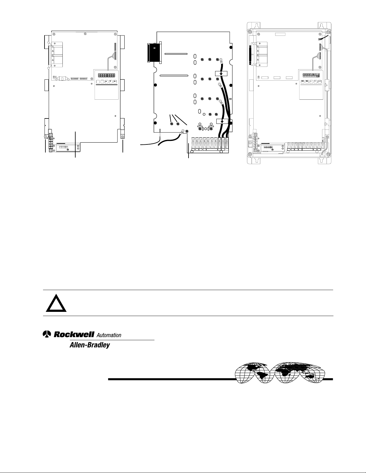
Remove and lock-out all incoming power to the 1336 REGEN Line Regeneration Package.
Remove the Precharge Unit front cov er . Measure the voltage at input power terminals R1–S1–T1 and terminal block
TB1 with a voltmeter to ensure that no voltage is present.
Remove the Converter front cover. Measure the voltage at input power terminals R2–S2–T2 with a voltmeter to
ensure that no voltage is present.
DC
–
toppedS
.00 Hz0
+
DO NOT USE
J4
PORT 2
PORT 1
T2S2R2
Disconnect leads, unplug connectors and loosen the (2) retaining screws to remove the Base Plate.
Disconnect leads and unplug connectors J1, J3 & P13 at the Gate Driver Board. Remove the (16) retaining screws to
remove the Gate Driver Board.
Install and reconnect all wires and cables to the new board at the same locations.
Reinstall the Converter Base Plate, reconnecting all leads and connectors. Reinstall the Converter front cover.
ATTENTION: Replace any guards or shields previously remov ed before reapplying power to the 1336 REGEN
Line Regeneration Package. Failure to replace guards or shields may result in death or serious injury.
!
Rockwell Automation helps its customers receive a superior return on their investment by bringing
together leading brands in industrial automation, creating a broad spectrum of easy-to-integrate
products. These are supported by local technical resources available worldwide, a global network
of system solutions providers, and the advanced technology resources of Rockwell.
Worldwide representation.
Argentina • Australia • Austria • Bahrain • Belgium • Bolivia • Brazil • Bulgaria • Canada • Chile • China, People’s Republic of • Colombia • Costa Rica • Croatia • Cyprus
Czech Republic • Denmark • Dominican Republic • Ecuador • Egypt • El Salvador • Finland • France • Germany • Ghana • Greece • Guatemala • Honduras • Hong Kong
Hungary • Iceland • India • Indonesia • Iran • Ireland • Israel • Italy • Jamaica • Japan • Jordan • Korea • Kuwait • Lebanon • Macau • Malaysia • Malta • Mexico
Morocco • The Netherlands • New Zealand • Nigeria • Norway • Oman • Pakistan • Panama • Peru • Philippines • Poland • Portugal • Puerto Rico • Qatar • Romania • Russia
Saudi Arabia • Singapore • Slovakia • Slovenia • South Africa, Republic of • Spain • Sweden • Switzerland • Taiwan • Thailand • Trinidad • Tunisia • Turkey • United Arab Emirates
United Kingdom • United States • Uruguay • Venezuela
Rockwell Automation Headquarters, 1201 South Second Street, Milwaukee, WI 53204-2496 USA, Tel: (1) 414 382-2000, Fax: (1) 414 382-4444
Publication 1336 REGEN-5.13 — May, 1998 P/N 191184 (01)
Copyright 1998 Rockwell International Corporation Printed in USA
 Loading...