

Page 1
1336 PLUS II
Adjustable
Frequency AC Drive
with
0.37-448 kW (0.5 - 600 HP)
Firmware 1.xxx - 6.xxx
User Manual
Page 2

Important User Information
Solid state equipment has operational characteristics differing from those of
electromechanical equipment. “Safety Guidelines for the Application,
Installation and Maintenance of Solid State Controls” (Publication SGI-1.1
available from your local Rockwell Automation Sales Office or online at
www.rockwellautomation.com/literature) describes some important
differences between solid state equipment and hard-wired
electromechanical devices. Because of this difference, and also because of
the wide variety of uses for solid state equipment, all persons responsible
for applying this equipment must satisfy themselves that each intended
application of this equipment is acceptable.
In no event will Rockwell Automation, Inc. be responsible or liable for
indirect or consequential damages resulting from the use or application of
this equipment.
The examples and diagrams in this manual are included solely for
illustrative purposes. Because of the many variables and requirements
associated with any particular installation, Rockwell Automation, Inc.
cannot assume responsibility or liability for actual use based on the
examples and diagrams.
No patent liability is assumed by Rockwell Automation, Inc. with respect to
use of information, circuits, equipment, or software described in this
manual.
Reproduction of the contents of this manual, in whole or in part, without
written permission of Rockwell Automation, Inc. is prohibited.
Throughout this manual we use notes to make you aware of safety
considerations.
ATTENTION: Identifies information about practices or
circumstances that can lead to personal injury or death, property
!
damage, or economic loss.
Attentions help you:
• identify a hazard
• avoid the hazard
• recognize the consequences
Important: Identifies information that is especially important for successful
application and understanding of the product.
Shock Hazard labels may be located on or inside the drive to
alert people that dangerous voltage may be present.
StepLogic and SCANport are trademarks of Rockwell Automation, Inc.
Trademarks not belonging to Rockwell Automation are property of their respective companies.
Page 3

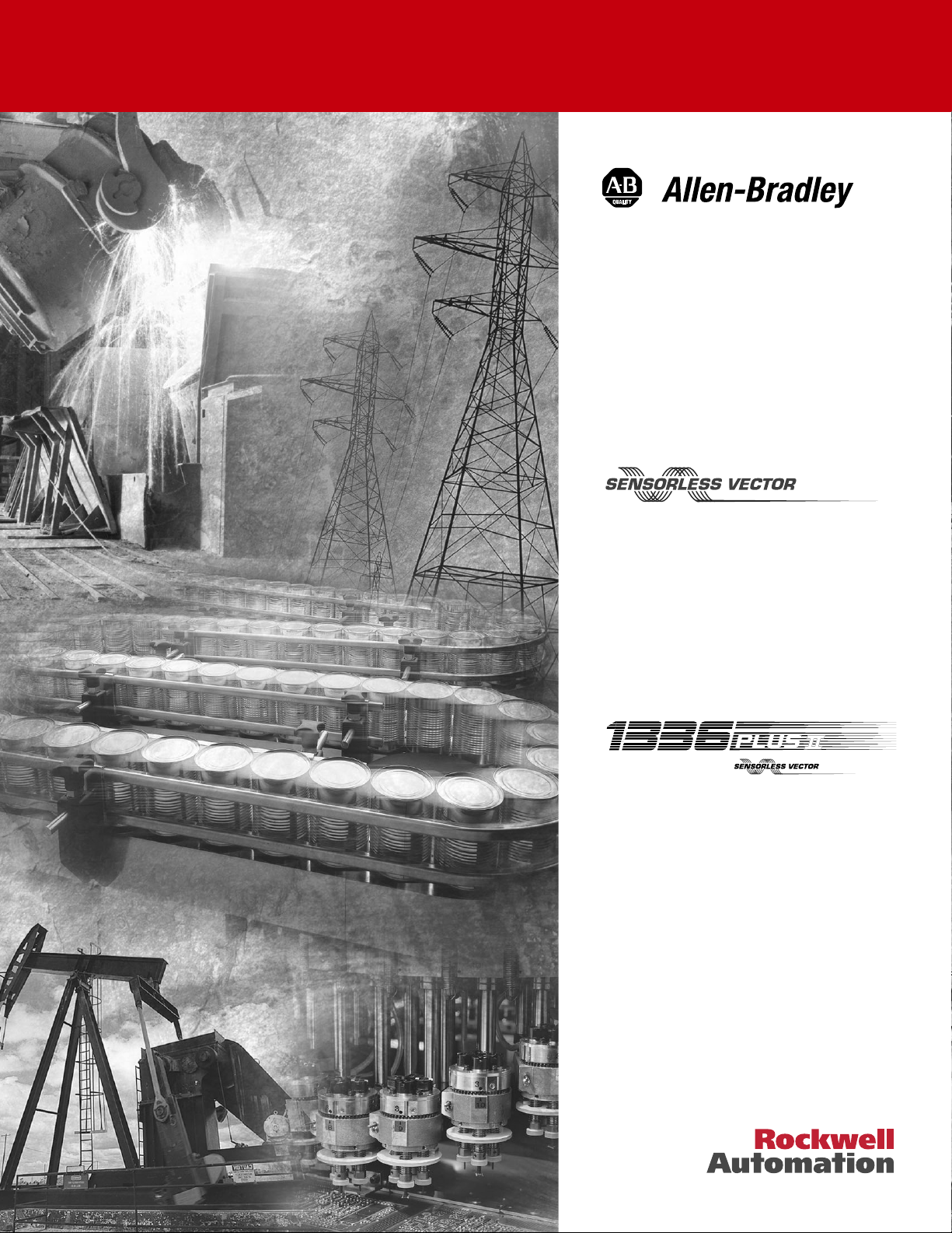
Summary of Changes
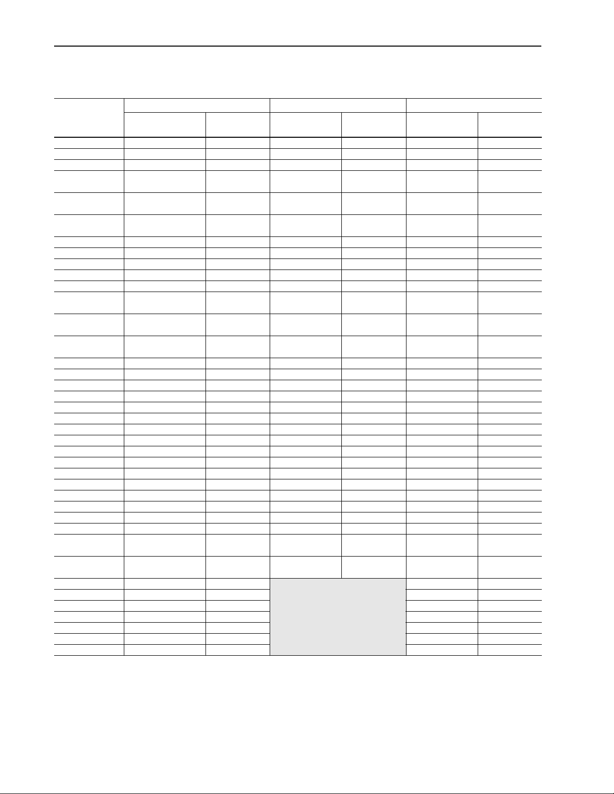
New/Updated Information The information below summarizes the changes to the 1336 PLUS II
User Manual since the last release.
Description of Change Page(s)
TB1 info updated - D Frame 2–15
Updated Parameters:
[Load Loss Level]
[Phase Loss Level]
[Heatsink Temp]
[Drive Type]
New Parameters:
[Motor OL Ret] 6–35
Parameter Cross References
updated
Parameter Record updated A–17
, B–18
6–26
6–35
6–39
6–42
A–8
Page 4

soc–2 Summary of Changes
Notes
Page 5

Table of Contents
Chapter 1
Information and Precautions Manual Objectives . . . . . . . . . . . . . . . . . . . . . . . . . . . . . . . . . . . . . . . . . . 1–1
Software Compatibility . . . . . . . . . . . . . . . . . . . . . . . . . . . . . . . . . . . . . . . 1–1
General Precautions . . . . . . . . . . . . . . . . . . . . . . . . . . . . . . . . . . . . . . . . . 1–2
Conventions Used in this Manual . . . . . . . . . . . . . . . . . . . . . . . . . . . . . . . 1–2
Catalog Number Explanation . . . . . . . . . . . . . . . . . . . . . . . . . . . . . . . . . . 1–2
Nameplate Location . . . . . . . . . . . . . . . . . . . . . . . . . . . . . . . . . . . . . . . . . 1–4
Chapter 2
Installation/Wiring Mounting . . . . . . . . . . . . . . . . . . . . . . . . . . . . . . . . . . . . . . . . . . . . . . . . . . 2–1
Installation Guidelines. . . . . . . . . . . . . . . . . . . . . . . . . . . . . . . . . . . . . . . . 2–2
AC Supply Source. . . . . . . . . . . . . . . . . . . . . . . . . . . . . . . . . . . . . . . . . . . 2–3
Input Power Conditioning . . . . . . . . . . . . . . . . . . . . . . . . . . . . . . . . . . . . . 2–4
Input Fuses and Circuit Breakers . . . . . . . . . . . . . . . . . . . . . . . . . . . . . . . 2–5
Input Devices . . . . . . . . . . . . . . . . . . . . . . . . . . . . . . . . . . . . . . . . . . . . . . 2–9
Electrical Interference - EMI/RFI . . . . . . . . . . . . . . . . . . . . . . . . . . . . . . . . 2–9
RFI Filtering . . . . . . . . . . . . . . . . . . . . . . . . . . . . . . . . . . . . . . . . . . . . . . 2–10
CE Conformity. . . . . . . . . . . . . . . . . . . . . . . . . . . . . . . . . . . . . . . . . . . . . 2–10
Grounding . . . . . . . . . . . . . . . . . . . . . . . . . . . . . . . . . . . . . . . . . . . . . . . . 2–11
Power Cabling. . . . . . . . . . . . . . . . . . . . . . . . . . . . . . . . . . . . . . . . . . . . . 2–14
Control and Signal Wiring . . . . . . . . . . . . . . . . . . . . . . . . . . . . . . . . . . . . 2–24
Digital Inputs . . . . . . . . . . . . . . . . . . . . . . . . . . . . . . . . . . . . . . . . . . . . . . 2–25
Encoder Inputs . . . . . . . . . . . . . . . . . . . . . . . . . . . . . . . . . . . . . . . . . . . . 2–30
Pulse Input/Output Option. . . . . . . . . . . . . . . . . . . . . . . . . . . . . . . . . . . . 2–31
Digital Outputs . . . . . . . . . . . . . . . . . . . . . . . . . . . . . . . . . . . . . . . . . . . . 2–31
Analog I/O . . . . . . . . . . . . . . . . . . . . . . . . . . . . . . . . . . . . . . . . . . . . . . . . 2–32
Standard Analog I/O Setup . . . . . . . . . . . . . . . . . . . . . . . . . . . . . . . . . . . 2–33
Optional Analog I/O Configurations . . . . . . . . . . . . . . . . . . . . . . . . . . . . 2–34
Output Devices . . . . . . . . . . . . . . . . . . . . . . . . . . . . . . . . . . . . . . . . . . . . 2–37
Cable Termination . . . . . . . . . . . . . . . . . . . . . . . . . . . . . . . . . . . . . . . . . . 2–37
Selecting/Verifying Fan Voltage . . . . . . . . . . . . . . . . . . . . . . . . . . . . . . . 2–38
Auxiliary Inputs - TB4, TB6 . . . . . . . . . . . . . . . . . . . . . . . . . . . . . . . . . . . 2–39
Auxiliary Output - TB9 . . . . . . . . . . . . . . . . . . . . . . . . . . . . . . . . . . . . . . . 2–40
Control Interface Board Installation and Removal. . . . . . . . . . . . . . . . . . 2–40
Adapter Definitions . . . . . . . . . . . . . . . . . . . . . . . . . . . . . . . . . . . . . . . . . 2–41
Chapter 3
Human Interface Module HIM Description . . . . . . . . . . . . . . . . . . . . . . . . . . . . . . . . . . . . . . . . . . . . 3–1
HIM Operation. . . . . . . . . . . . . . . . . . . . . . . . . . . . . . . . . . . . . . . . . . . . . . 3–4
Handheld HIM Operation . . . . . . . . . . . . . . . . . . . . . . . . . . . . . . . . . . . . 3–13
Chapter 4
Flash Memory What is Flash Memory? . . . . . . . . . . . . . . . . . . . . . . . . . . . . . . . . . . . . . . 4–1
Firmware Download Requirements. . . . . . . . . . . . . . . . . . . . . . . . . . . . . . 4–1
Page 6

toc–ii Table of Contents
Chapter 5
Start-Up Start-Up Requirements . . . . . . . . . . . . . . . . . . . . . . . . . . . . . . . . . . . . . . 5–1
Initial Operation . . . . . . . . . . . . . . . . . . . . . . . . . . . . . . . . . . . . . . . . . . . . 5–2
Assisted Start-Up . . . . . . . . . . . . . . . . . . . . . . . . . . . . . . . . . . . . . . . . . . . 5–2
Advanced Start-Up. . . . . . . . . . . . . . . . . . . . . . . . . . . . . . . . . . . . . . . . . . 5–5
Chapter 6
Programming Function Index . . . . . . . . . . . . . . . . . . . . . . . . . . . . . . . . . . . . . . . . . . . . . 6–1
Programming Flow Chart . . . . . . . . . . . . . . . . . . . . . . . . . . . . . . . . . . . . . 6–1
Chapter Conventions . . . . . . . . . . . . . . . . . . . . . . . . . . . . . . . . . . . . . . . . 6–4
Chapter 7
Troubleshooting Fault Descriptions . . . . . . . . . . . . . . . . . . . . . . . . . . . . . . . . . . . . . . . . . . 7–1
Alarms . . . . . . . . . . . . . . . . . . . . . . . . . . . . . . . . . . . . . . . . . . . . . . . . . . . 7–9
Appendix A
Specifications and
Supplemental Information
Specifications . . . . . . . . . . . . . . . . . . . . . . . . . . . . . . . . . . . . . . . . . . . . . . A–1
User Supplied Enclosures . . . . . . . . . . . . . . . . . . . . . . . . . . . . . . . . . . . . A–4
Derating Guidelines . . . . . . . . . . . . . . . . . . . . . . . . . . . . . . . . . . . . . . . . . A–5
Parameter Cross Reference - By Number . . . . . . . . . . . . . . . . . . . . . . . . A–8
Parameter Cross Reference - By Name. . . . . . . . . . . . . . . . . . . . . . . . . . A–9
HIM Character Map . . . . . . . . . . . . . . . . . . . . . . . . . . . . . . . . . . . . . . . . A–10
Communications Data Information Format . . . . . . . . . . . . . . . . . . . . . . A–11
Typical Programmable Controller Communications Configurations . . . . A–12
Typical Serial Communications Configurations . . . . . . . . . . . . . . . . . . . A–13
Encoder Interface Wiring . . . . . . . . . . . . . . . . . . . . . . . . . . . . . . . . . . . . A–14
Read/Write Parameter Record . . . . . . . . . . . . . . . . . . . . . . . . . . . . . . . . A–17
Appendix B
Dimensions
Appendix C
CE Conformity Requirements for Conforming Installation . . . . . . . . . . . . . . . . . . . . . . . . C–2
Filter . . . . . . . . . . . . . . . . . . . . . . . . . . . . . . . . . . . . . . . . . . . . . . . . . . . . . C–2
Electrical Configuration . . . . . . . . . . . . . . . . . . . . . . . . . . . . . . . . . . . . . . C–3
Grounding . . . . . . . . . . . . . . . . . . . . . . . . . . . . . . . . . . . . . . . . . . . . . . . . C–4
Mechanical Configuration. . . . . . . . . . . . . . . . . . . . . . . . . . . . . . . . . . . . . C–4
Page 7

Chapter 1
Information and Precautions
Chapter 1 provides information on the general intent of this manual, gives an overall description of the 1336
Frequency AC Drive and provides a listing of key drive features.
Manual Objectives This publication provides planning, installation, wiring and diag-
nostic information for the 1336
ful installation and operation, the material presented must be
thoroughly read and understood before proceeding. Particular
attention must be directed to the Attention and Important statements contained within.
For J Frame information, refer to publication 1336F-IN014.
PLUS II Drive. To assure success-
Software Compatibility
Three-Phase Drive Rating
0.37-0.75 kW
0.5-1 HP
1.2-1.5 kW
1.5-2 HP
2.2-3.7 kW
3-5 HP
5.5 kW
7.5 HP
5.5-11 kW
7.5-15 HP
15-22 kW
20-30 HP
30-45 kW
40-60 HP
56-93 kW
75-125 HP
– 187-336 kW
– 187-448 kW
1
kW and HP are constant torque.
0.37-1.2 kW
0.5-1.5 HP
1.5-2.2 kW
2-3 HP
3.7 kW
5 HP
5.5-15 kW
7.5-20 HP
11-22 kW
15-30 HP
30-45 kW
40-60 HP
45-112 kW
60-150 HP
112-187 kW
150-250 HP
250-450 HP
250-600 HP
1
– 1.0 & Up A1
– 1.0 & Up A2
– 1.0 & Up A3
0.75-15 kW
1-20 HP
– 1.0 & Up B1/B2
18.5-45 kW
25-60 HP
56-93 kW
75-125 HP
112-224 kW
150-300 HP
261-298 kW
350-400 HP
224-448 kW
300-600 HP
PLUS II Adjustable
Compatible with
Version . . .
1.0 & Up A4
1.0 & Up C
1.0 & Up D
1.0 & Up E
1.0 & Up F
1.0 & Up G
Frame
Reference200-240V 380-480V 500-600V
Page 8

1–2 Information and Precautions
General Precautions
ATTENTION: This drive contains ESD (Electrostatic
!
!
Discharge) sensitive parts and assemblies. Static control
precautions are required when installing, testing, servicing
or repairing this assembly. Component damage may result
if ESD control procedures are not followed. If you are not
familiar with static control procedures, reference A-B
publication 8000-4.5.2, “Guarding Against Electrostatic
Damage” or any other applicable ESD protection
handbook.
ATTENTION: An incorrectly applied or installed drive
can result in component damage or a reduction in product
life. Wiring or application errors, such as, undersizing the
motor, incorrect or inadequate AC supply, or excessive
ambient temperatures may result in malfunction of the
system.
ATTENTION: Only personnel familiar with the 1336
PLUS II Adjustable Frequency AC Drive and associated
machinery should plan or implement the installation, startup and subsequent maintenance of the system. Failure to
comply may result in personal injury and/or equipment
damage.
ATTENTION: To avoid a hazard of electric shock, verify
that the voltage on the bus capacitors has discharged before
performing any work on the drive. Measure the DC bus
voltage at the + & - terminals of TB1. The voltage must be
0.0V DC.
Conventions Used in this
Manual
!
!
To help differentiate parameter names and display text from other text
the following conventions will be used:
• Parameter Names will appear in [brackets]
• Display Text will appear in “quotes”
Catalog Number Explanation The diagram on the following page describes the 1336 PLUS II
catalog numbering scheme.
Page 9
Information and Precautions 1–3
1336F
First Position
Bulletin Number
–
BR
Second Position
Vol ta ge
Letter Voltages
AQ 200-240V AC or
BR 380-480VAC or
CW 500-600V AC or
A 200-240V AC
B 380-480V AC
BP/BPR➃ 380-480V AC
BX Special Rating
C 500-600V AC
CP/CPR ➃ 500-600V AC
Q 310V DC
R 513-620V DC
RX Special Rating
W 775V DC
310V DC
513-620V DC
775V DC
(F Frame)
(F Frame)
F30
Third Position
Nominal HP Rating
Refer to table below for
ratings and possible
voltage combinations.
Voltage and Nominal HP Rating Combinations
Code Rating AQ BR CW A B
F05 0.37 (0.5) ●●
F07 0.56 (0.75) ●●
F10 0.75 (1) ●● ●
F15 1.2 (1.5) ●●
F20 1.5 (2) ●● ●
F30 2.2 (3) ●● ●
F50 3.7 (5) ●● ●
F75 5.5 (7.5) ●● ●
F100 7.5 (10) ●●
F150 11 (15) ●●
F200 15 (20) ●●
007 5.5 (7.5) ●●
010 7.5 (10) ●●
015 11 (15) ●● ●●
020 15 (20) ●● ●●
025 18.5 (25) ●● ● ●● ●
030 22 (30) ●● ● ●● ●
040 30 (40) ●● ● ● ●● ● ●
050 37 (50) ●● ● ●● ●
060 45 (60) ●● ● ● ●● ● ●
075 56 (75) ●● ● ●● ●
100 75 (100) ●● ● ●● ●
125 93 (125) ●● ● ●● ●
150 112 (150) ●●● ●●●
200 149 (200) ●●●●
250 187 (250) ➁●●●●●●●
300 224 (300) ➁●●●●●
350 261 (350) ➁●●●●●●
400 298 (400) ➁●●●●●●
450 336 (450) ➁●●●●●
500 373 (500) ➁●●●●
600 448 (600) ●●●●
➀ Language must be specified to ensure shipment of appropriate User Manual.
➁ G Frame Standard Drives in enclosed construction are supplied through the Configured Drives
Program and will have an “A” suffix after the HP rating.
➂ D through G Frame drives in IP 65 (NEMA Type 4) and IP 54 (NEMA Type 12) configurations are
supplied through the Configured Drives Program.
➃ “xPR” has a “roll-in” type chassis. ➄ Not available with v5.001 & later.
BP/
BPR BX C
CP/
CPR Q R RX W
–
AA
Fourth Position
Enclosure Type
Code Type
AA IP 20 (NEMA 1)
AE IP 20 (NEMA 1)/EMC
AF IP 65 (NEMA 4) ➂
AJ IP 54 (NEMA 12) ➂
AN IP 00 (Open)
Code Description
Human Interface Module, Snap-In, IP20 (NEMA Type 1)
HASB Snap-In Cradle/Blank Plate
HASP Programmer Only
HCSP Programmer Only & Upload/Download Capability
HAS1 Programmer/Controller w/Analog Pot
HCS1 Programmer/Controller w/Analog Pot & Upload/Download Capability
HAS2 Programmer/Controller w/Digital Pot
HCS2 Programmer/Controller w/Digital Pot & Upload/Download Capability
Human Interface Module, IP65/54 (NEMA Type 4/12)
HJP Programmer Only
HJ2 Programmer/Controller w/Digital Pot
Communication Options –- B Frame & Up (Adapter 6)
GM1 Single Point Remote I/O B Frame
GM2 RS-232/422/485, DF1 & DH485 B Frame
GM5 DeviceNet™
GM6 Enhanced DeviceNet™
Communication Options –- All Frames (Adapter 1)
GMS1 GM1 with Snap-In Cradle
GMS2 GM2 with Snap-In Cradle
GMS5 GM5 with Snap-In Cradle
GMS6 GM6 with Snap-In Cradle
Control Interface Options
L4 TTL Contact
L4E TTL Contact & Encoder Feedback
L7E TTL Contact & Encoder Fdbck. for use with Encoder Loss Detection
L5 24V AC/DC
L5E 24V AC/DC & Encoder Feedback
L8E 24V AC/DC & Encoder Feedback for use with Encoder Loss Detection
L6 115V AC
L6E 115V AC & Encoder Feedback
L9E 115V AC & Encoder Feedback for use with Encoder Loss Detection
Analog Interface Options – Slot A
• Choose No More than One – Configurable Inputs/Outputs are 10V or 20mA
LA2 Two Isolated Configurable Inputs
LA6 One Isolated Bi-polar Input (±10V or ±20mA) and One Isolated
LA7 One Isolated Bi-polar Input (±10V or ±20mA) and One Isolated
Analog Interface Options – Slot B
• Choose No More than One – Configurable Inputs/Outputs are 10V or 20mA
LA1 Single-ended, Non-isolated Configurable (including Pot) Input & 2
LA3 Two Isolated Configurable Outputs
LA4 One Isolated Configurable Input & Output
LA5 Isolated Pulse Input, Non-isolated Pulse Output & Single-ended,
Common Mode Choke –- F & G Frame (must be specified for F Frame)
CM Internal Common Mode Choke (factory installed)
NCM No Common Mode Choke
Thermistor Input
Configurable Input
Single-ended, Non-isolated Outputs (1 - Configurable, 1 - 20mA)
Non-isolated Configurable Output
–
EN
Fifth Position
Language Group➀
Code Language
EN English
FR French
DE German
IT Italian
ES Spanish
JP Japanese ➄
–
MODS
Sixth Position
Options
Page 10
1–4 Information and Precautions
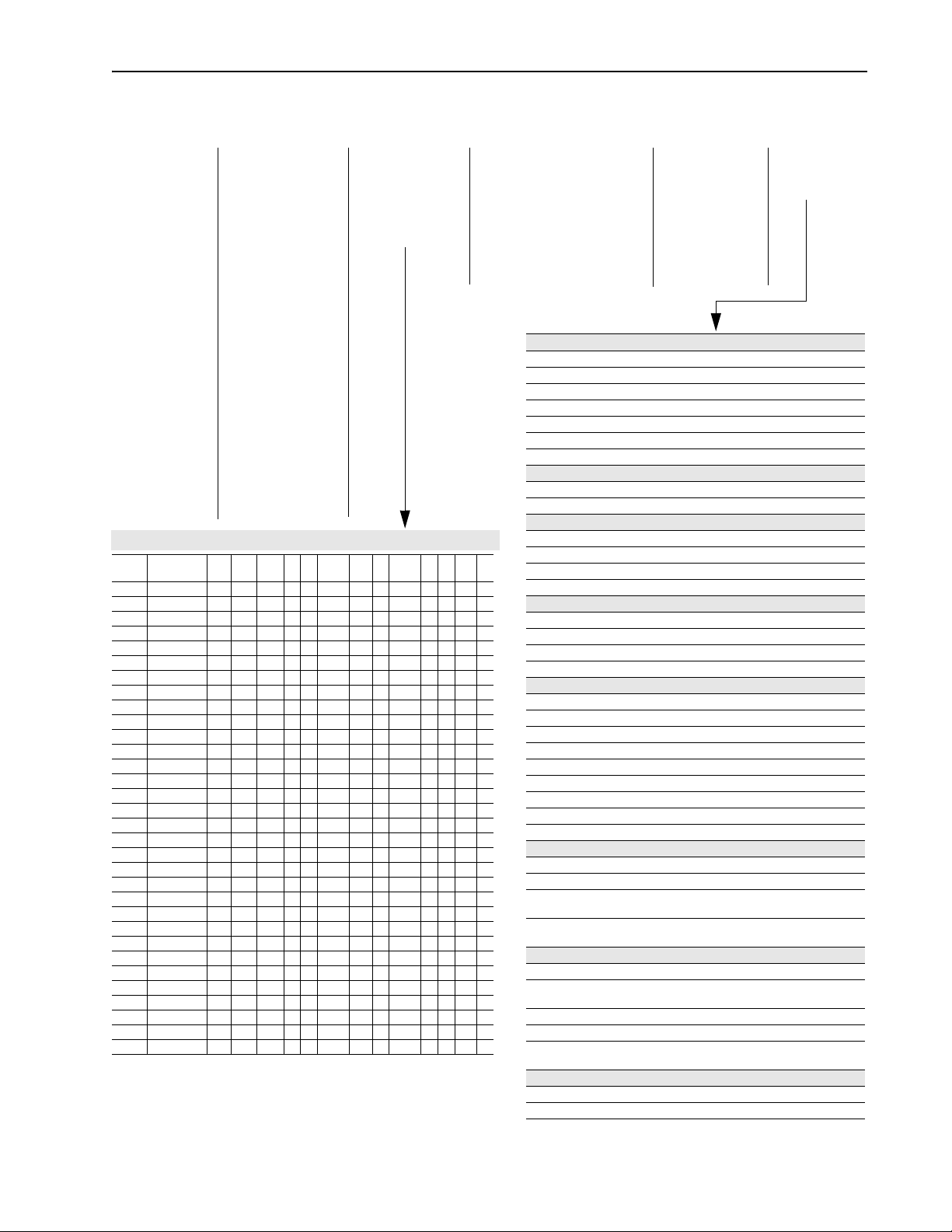
Nameplate Location Figure 1.1
1336
PLUS II Nameplate Location
1
Refer to page 1-1 for frame reference classifications.
ESC SEL
JOG
Nameplate Located on
Bottom Portion of
Chassis Behind Cover
Frames1 A1, A2, A3, A4
Nameplate Located on
Mounting Plate of
Main Control Board
Frames
1
B - G
Page 11
Chapter 2
Installation/Wiring
Chapter 2 provides the information you need to properly mount
and wire the 1336
are the result of incorrect wiring, every precaution must be taken
to assure that the wiring is done as instructed. All items must be
read and understood before the actual installation begins.
ATTENTION: The following information is merely a
guide for proper installation. The Allen-Bradley
!
Company cannot assume responsibility for the
compliance or the noncompliance to any code, national,
local or otherwise for the proper installation of this drive
or associated equipment. A hazard of personal injury
and/or equipment damage exists if codes are ignored
during installation.
PLUS II Drive. Since most start-up difficulties
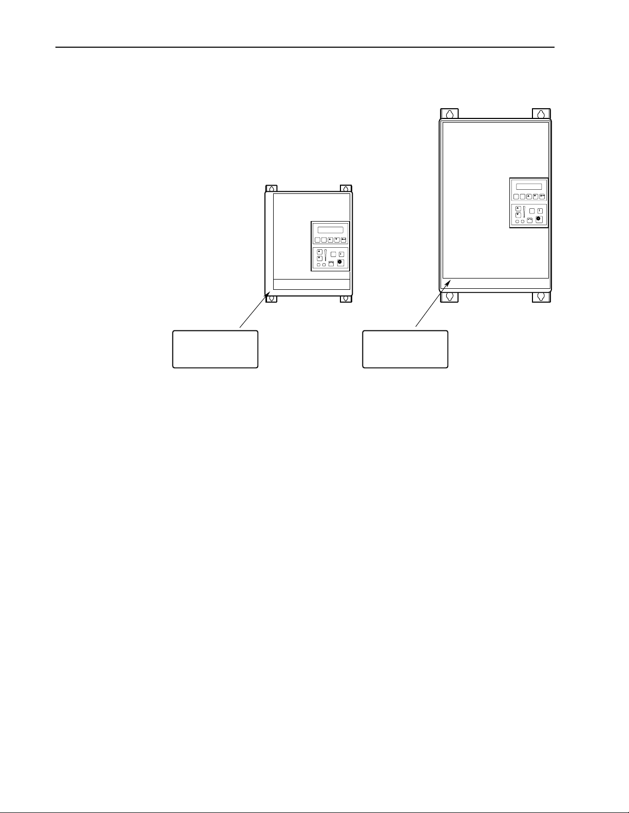
Mounting Minimum Mounting Requirements for Proper Heat Dissipation
(Dimensions shown are between drives or other devices)
152.4 mm
(6.0 in.)
101.6 mm
(4.0 in.)
ESC SEL
JOG
UP
152.4 mm
(6.0 in.)
Important:
A4 Frame drives should not be mounted on a combustible surface. However,
if the drive must be mounted on a combustible surface, 6.35 mm (0.25 in.)
spacers must be provided under the mounting feet of the drive.
152.4 mm
(6.0 in.)
ESC
JOG
152.4 mm
(6.0 in.)
F Frame drives require a minimum of 152.4 mm (6.0 in.) between the drive back
and mounting wall, if drives are mounted with sides touching another device or wall.
A minimum of 76.2 mm (3.0 in.) is required on the sides if the back of the drive is
mounted against a wall or other device.
Page 12
2–2 Installation/Wiring
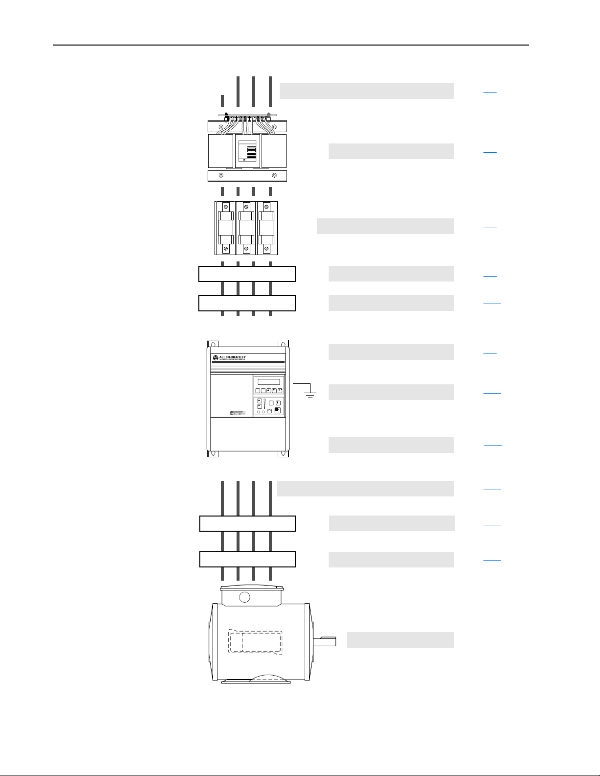
Installation Guidelines
GND
PE
R
GND
(L1)S(L2)T(L3)
CAT. NO.
FREQUENCY
POWER RATING
PRIMARY VOLTAGE
SECONDARY VOLTAGE
INSULATION CLASS
NO. OF PHASES
VENDOR PART NO.
AC Supply Source
ALLEN-BRADLEY
Input Power Conditioning
Input Fusing & Circuit Breakers
Input Devices
Input Filters
Electrical Interference
Page 2–3
Page 2–4
Page 2–5
Page 2–9
Page 2–10
Page 2–9
PE
GND
(T1)
U
ESC SEL
JOG
(T2)V(T3)
W
Grounding
Power Cabling
Control & Signal Cabling
Output Devices
Cable Termination
Motor
Page 2–11
Page 2–14
Page 2–24
Page 2–37
Page 2–37
Page 13
Installation/Wiring 2–3
AC Supply Source 1336 PLUS II drives are suitable for use on a circuit capable of deliv-
ering up to a maximum of 200,000 rms symmetrical amperes, 600
volts. Refer to Table 2.A
circuit breaker choice.
ATTENTION: To guard against personal injury and/or
equipment damage caused by improper fusing, use only the
!
recommended line fuses specified in Tab l e 2. A
Unbalanced Distribution Systems
This drive is designed to operate on three-phase supply systems
whose line voltages are symmetrical. Surge suppression devices are
included to protect the drive from lightning induced overvoltages
between line and ground. Where the potential exists for abnormally
high phase-to-ground voltages (in excess of 125% of nominal), or
where the supply ground is tied to another system or equipment that
could cause the ground potential to vary with operation, suitable isolation is required for the drive. Where this potential exists, an isolation transformer is strongly recommended.
for actual interrupt ratings based on fuse or
.
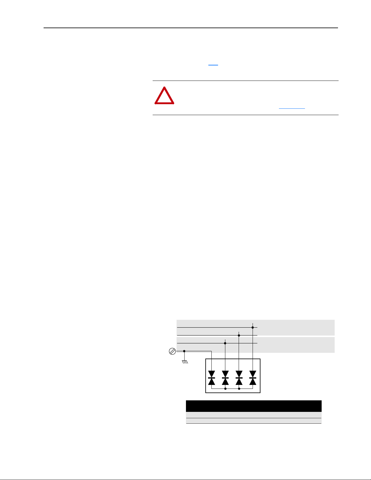
Ungrounded Distribution Systems
All 1336 PLUS II drives are equipped with an MOV (Metal Oxide
Varistor) that provides voltage surge protection and phase-to-phase
plus phase-to-ground protection which is designed to meet IEEE 587.
The MOV circuit is designed for surge suppression only (transient
line protection), not continuous operation.
With ungrounded distribution systems, the phase-to-ground MOV
connection could become a continuous current path to ground.
Energy ratings are listed below. Exceeding the published phase-tophase or phase-to-ground energy ratings may cause physical damage
to the MOV. Refer to page A-1.
Joules (J)
Joules (J)
1234
Phase-to-Phase MOV Rating
Includes 2 Phase-Phase MOVs
Phase-to-Ground MOV Rating
Includes Phase-Phase & Phase-Ground MOVs
Three-Phase
AC Input
Ground
R
S
T
Joules (J)
Joules (J)
Frame Reference
Device Rating (V AC)
Phase-Phase Total
Phase-Ground Total
A
240 480/600
160J 320J
220J 380J
B-C
240/480 600
280J 320J
360J 410J
D-G
240/480 600
280J 300J
360J 370J
Page 14

2–4 Installation/Wiring
V
Input Power Conditioning In general, the 1336 PLUS II is suitable for direct connection to an AC
line of the correct voltage. Certain conditions can exist, however, that
prompt consideration of a line reactor or isolation transformer ahead
of the drive.
The basic rules to aid in determining whether a line reactor or isolation transformer should be considered are as follows:
1. If the AC source experiences frequent power outages or signifi-
cant voltage transients, users should calculate the VA
mula below). If the source transformer VA exceeds the calculated
and the drive is installed close to the source, it is an indication
VA
max
that there may be enough energy behind these voltage transients to
cause nuisance input fuse blowing, overvoltage faults or drive power
structure damage. In these cases, a line reactor or isolation transformer should be considered.
Z
VA
drive
max
(Ω/Φ) =
(V
=
line-line
line-line
√3 x Input Amps
)2 x % Source Leakage (5-6% typical)
x 0.01
Z
drive
(see for-
max
2. If the AC source does not have a neutral or one phase referenced
to ground (see Unbalanced Distribution Systems on page 2–3
), an
isolation transformer with the neutral of the secondary grounded is
highly recommended.
If the line-to-ground voltages on any phase
can exceed 125% of the nominal line-to-line voltage, an isolation
transformer with the neutral of the secondary grounded, is highly
recommended.
3. If the AC line supplying the drive has power factor correction
capacitors that are switched in and out, an isolation transformer
or 5% line reactor is recommended between the drive and capacitors. If the capacitors are permanently connected and not
switched, the general rules above apply.
Page 15

Installation/Wiring 2–5
Input Fuses and Circuit
Breakers
The 1336 PLUS II can be installed with either input fuses or an input
circuit breaker. Local/national electrical codes may determine additional requirements for these installations.
The tables on the following pages provide drive ratings and recommended AC line input fuse and circuit breaker information. Both
types of short circuit protection are acceptable for UL and IEC
requirements. Sizes listed are the recommended sizes based on 40
degree C and the U.S. N.E.C. Other country, state or local codes may
require different ratings.
ATTENTION: The 1336 PLUS II does not provide input
power short circuit protection. Specifications for the recom-
!
mended fuse or circuit breaker to provide drive input power
protection against short circuits are provided.
Fusing
If fuses are chosen as the desired protection method, refer to the
recommended types listed below. If available amp ratings do not
match the tables provided, the closest
drive rating should be chosen.
• IEC – BS88 (British Standard) Parts 1 & 2
2, type gG or equivalent should be used.
• UL – UL Class CC, T, RK1 or J must be used.
fuse rating that exceeds the
1
, EN60269-1, Parts 1 &
Circuit Breakers
The “non-fuse” listings in the following tables include both circuit
breakers (inverse time or instantaneous trip) and 140M Self-Protecting Motor Starters. If one of these is chosen as the desired protec-
tion method, the following requirements apply.
• IEC and UL – Both types of devices are acceptable for IEC and UL
installations
1. Typical designations include, but may not be limited to the following; Parts 1 & 2: AC, AD, BC, BD, CD,
DD, ED, EFS, EF, FF, FG, GF, GG, GH.
Page 16

2–6 Installation/Wiring
Table 2.A
240 Volt Input Protection Devices
Drive
Catalog
Number
1336F- HP
Frame
Input
Rating
Amps Amps Min.1Max.2Min.1Max.2Max.8Max.
Output
Rating
Dual-Element
Time Delay
Fuse
Non-Time
Delay Fuse
Circuit
Breaker
A1 F05 0.5 2.8 2.3 4 5 4 6 15 3 140M-C2E-B40 140M-D8E-B40 – –
F07 0.75 3.5 3.0 4 6 4 9 15 7 140M-C2E-B40 140M-D8E-B40 – –
F10 1 5.4 4.5 6 9 6 12 15 7 140M-C2E-B63 140M-D8E-B63 – –
A2 F15 1.5 7.3 6.0 8 12.5 8 15 20 15 140M-C2E-C10 140M-D8E-C10 140M-F8E-C10 –
F20 2 9.7 8.0 10 15 10 20 25 15 140M-C2E-C10 140M-D8E-C10 140M-F8E-C10 –
A3 F30 3 14.3 12.0 15 20 15 25 35 15 140M-C2E-C16 140M-D8E-C16 140M-F8E-C16 –
F50 5 21.3 18.0 25 30 25 45 60 30 140M-C2E-C25 140M-D8E-C25 140M-F8E-C25 140M-CMN-2500
F75 7.5 22.6 22.0 30 45 30 60 80 50 140M-C2E-C25 140M-D8E-C25 140M-F8E-C25 140M-CMN-2500
B 007 7.5 28.0 27.0 40 45 40 60 80 50 – – 140M-F8E-C32 140M-CMN-4000
010 10 35.0 34.0 50 60 50 80 100 50 – – – 140M-CMN-4000
015 15 49.0 48.0 70 90 70 110 150 70 – – – 140M-CMN-6300
C 020 20 63.0 65.0 100 110 100 125 200 100 – – – 140M-CMN-9000
025 25 75.0 77.0 100 150 100 200 250 100 – – – 140M-CMN-9000
030 30 79.0 80.0 125 175 125 225 300 150 – – – 140M-CMN-9000
D 040 40 119.0 120.0 120 225 120 300 300 150 – – – –
050 50 149.0 150.0 200 250 200 350 350 250 – – – –
060 60 178.0 180.0 250 300 250 450 450 250 – – – –
E 075 75 238.0 240.0 300 400 300 500 500 250 – – – –
100 100 289.0 291.0 400 500 400 700 700 400 – – – –
125 125 322.0 325.0 450 700 450 800 800 600 – – – –
1
Minimum protection device size is the lowest rated device that supplies maximum protection without nuisance tripping.
2
Maximum protection device size is the highest rated device that supplies drive protection.
3
Circuit Breaker - inverse time breaker.
4
Motor Circuit Protector - instantaneous trip circuit breaker.
5
Bulletin 140M with adjustable current range should have the current trip set to the minimum range that the device will not trip.
6
Manual Self-Protected (Type E) Combination Motor Controller, UL listed for 208 Wye or Delta, 240 Wye or Delta, 480Y/277 or 600Y/ 347. Not UL listed for use on 480V
or 600V Delta/Delta systems.
7
The AIC ratings of the Bulletin 140M Motor Protector may vary. See publication 140M-SG001B-EN-P.
8
Maximum rating allowed by US NEC. Exact size must be chosen for each installtion.
9
The Maximum Short Circuit Rating of a Cutler-Hammer Series HMCP is 100,000A at 240 volts, 65,000A at 480 volts and 25,000A at 575 volts.
Motor
Circuit
3
Protector
4,9
140M Motor Starter with Adjustable Current Range
8
Available Catalog Numbers
7
5, 6
Page 17

Installation/Wiring 2–7
Table 2.A (continued)
480 Volt Input Protection Devices
CT Ratings VT Ratings
Drive
Catalog
Number
1336F-
Frame
Input Output
HP
Amps Amps Amps Amps Min.
Input Output
HP
Dual Element
Time Delay
Fuse
1
Non-Time
Delay Fuse
Max.2Min.1Max.2Max.8Max.8Available Catalog Numbers - 140 . . .
A1 F05 0.5 1.3 1.1 0.5 1.4 1.2 3 2.5 3 3 15 3 M-C2E-B16 – – –
F07 0.75 2.0 1.6 0.75 2.1 1.7 3 3 3 6 15 3 M-C2E-B25 – – –
F10 1 2.6 2.1 1 2.8 2.3 3 4.5 3 8 15 3 M-C2E-B40 M-D8E-B40 – –
F15 1.5 3.3 2.8 1.5 3.5 3.0 4 6 4 12 15 7 M-C2E-B40 M-D8E-B40 – –
A2 F20 2 4.6 3.8 2 4.8 4.0 5 6 5 12 15 7 M-C2E-C63 M-D8E-C63 – –
F30 3 6.4 5.3 3 7.2 6.0 8 10 8 15 25 7 M-C2E-C10 M-D8E-C10 M-F8E-C10 –
A3 F50 5 10.0 8.4 5 10.7 9.0 12 15 12 30 35 15 M-C2E-C16 M-D8E-C16 M-F8E-C16 –
A4 F75 7.5 13.6 13.3 10 15.7 15.4 20 30 20 50 50 30 M-C2E-C16 M-D8E-C16 M-F8E-C16 –
F100 10 16.4 16.1 15 22.4 22.0 30 40 30 80 80 30 M-C2E-C25 M-D8E-C25 M-F8E-C25 -CMN-2500
F150 15 24.5 24.0 20 24.5 24.0 35 60 35 100 100 50 M-C2E-C25 M-D8E-C25 M-F8E-C25 -CMN-2500
F200 20 28.0 27.0 20 28.0 27.0 35 60 35 100 100 50 – – M-F8E-C32 -CMN-4000
B 015 15 25.0 24.2 20 28.0 27.0 35 60 35 100 100 50 – – M-F8E-C32 -CMN-4000
020 20 32.0 31.0 25 35.0 34.0 45 70 45 125 125 50 – – M-F8E-C45 -CMN-4000
025 25 40.0 39.0 30 43.0 42.0 60 90 60 150 150 70 – – M-F8E-C45 -CMN-6300
030 30 46.0 45.0 30 49.0 48.0 70 90 70 150 150 70 – – – -CMN-6300
C X040 40 61.0 59.0 40 61.0 59.0 80 110 80 200 200 70 – – – -CMN-6300
040 40 58.0 60.0 50 63.0 65.0 80 125 80 250 250 100 – – – -CMN-6300
050 50 73.0 75.0 60 75.0 77.0 100 150 100 300 300 100 – – – -CMN-9000
X060 60 75.0 77.0 60 75.0 77.0 100 150 100 300 300 100 – – – -CMN-9000
D 060 60 82.0 85.0 75 93.0 96.0 125 200 125 350 350 150 – – – –
075 75 105.0 106.0 100 119.0 120.0 150 250 150 450 350 250 – – – –
100 100 137.0 138.0 125 149.0 150.0 200 350 200 600 450 250 – – – –
125 125 172.0 173.0 150 178.0 180.0 250 400 250 600 500 250 – – – –
X150 150 178.0 180.0 150 178.0 180.0 250 400 250 600 500 250 – – – –
E 150 150 197.0 199.0 200 238.0 240.0 300 500 300 700 700 400 – – – –
200 200 261.0 263.0 250 290.0 292.0 400 600 400 800 800 400 – – – –
250 250 322.0 325.0 250 322.0 325.0 450 600 450 800 800 400 – – – –
F P250 250 322.0 325.0 300 357.0 360.0 450 –
P300 300 357.0 360.0 350 421.0 425.0 500 –
P350 350 421.0 425.0 400 471.0 475.0 600 –
P400 400 471.0 475.0 450 527.0 532.0 600 –
Refer to the 1336 Spare Parts list (publication 1336-6.5) for replacement information.
P450 450 527.0 532.0 700 –
G X250 250 322.0 325.0 300 357.0 360.0 450 –
300 300 357.0 360.0 350 421.0 425.0 450 –
350 350 421.0 425.0 400 471.0 475.0 500 –
400 400 471.0 475.0 450 521.0 525.0 600/630 –
450 450 521.0 525.0 500 585.0 590.0 800 –
500 500 585.0 590.0 600 664.0 670.0 800 –
600 600 664.0 670.0 600 664.0 670.0 900 -
1
Minimum protection device size is the lowest rated device that supplies maximum protection without nuisance tripping.
2
Maximum protection device size is the highest rated device that supplies drive protection.
3
Circuit Breaker - inverse time breaker.
4
Motor Circuit Protector - instantaneous trip circuit breaker.
5
Bulletin 140M with adjustable current range should have the current trip set to the minimum range that the device will not trip.
6
Manual Self-Protected (Type E) Combination Motor Controller, UL listed for 208 Wye or Delta, 240 Wye or Delta, 480Y/277 or 600Y/ 347. Not UL listed for use on 480V
or 600V Delta/Delta systems.
7
The AIC ratings of the Bulletin 140M Motor Protector may vary. See publication 140M-SG001B-EN-P.
8
Maximum rating allowed by US NEC. Exact size must be chosen for each installtion.
9
The Maximum Short Circuit Rating of a Cutler-Hammer Series HMCP is 100,000A at 240 volts, 65,000A at 480 volts and 25,000A at 575 volts.
Motor
Circuit
Circuit
Breaker
Protector
3
4,9
140M Motor Starter with Adjustable Current Range
6
Semiconductor fuse supplied with drive.
Bussmann Type FWP, SPP, or 170M Series
Ferraz Shawmut Type A-70Q, A-70QS or A070URD Series
7
5,
Page 18

2–8 Installation/Wiring
Table 2.A (continued)
575 Volt Input Protection Devices
CT Ratings
Drive
Catalog
Number
1336F-
Frame
A4 F10 1 2.4 2.0 3 3 3 6 15 3 140M-C2E-B25 – – –
F20 2 4.8 4.0 6 6 6 10 15 7 140M-C2E-C63 140M-D8E-C63 – –
F30 3 7.2 6.0 10 12 10 15 15 7 140M-C2E-C10 140M-D8E-C10 140M-F8E-C10 –
F50 5 9.6 8.0 15 20 15 20 20 15 140M-C2E-C10 140M-D8E-C10 140M-F8E-C10 –
F75 7.5 10.0 10.0 15 20 15 30 35 15 140M-C2E-C10 140M-D8E-C10 140M-F8E-C10 –
F100 10 12.0 12.0 20 25 20 40 40 15 140M-C2E-C16 140M-D8E-C16 140M-F8E-C16 –
F150 15 19.0 19.0 25 35 25 60 60 30 140M-C2E-C20 140M-D8E-C20 140M-F8E-C20 140-CMN-2500
F200 20 25.0 24.0 30 45 30 80 80 30 140M-C2E-C25 140M-D8E-C25 140M-F8E-C25 140-CMN-2500
C 025 25 31.0 30.0 40 60 40 100 100 50 – – 140M-F8E-C32 140-CMN-4000
030 30 36.0 35.0 50 70 50 125 125 50 – – 140M-F8E-C45 140-CMN-4000
040 40 44.0 45.0 60 90 60 150 150 70 – – 140M-F8E-C45 140-CMN-6300
050 50 55.0 57.0 80 110 80 200 200 70 – – – 140M-CMN-6300
060 60 60.0 62.0 90 125 90 225 225 100 – – – 140M-CMN-6300
D 075 75 84.0 85.0 110 150 110 300 300 100 – – – 140M-CMN-9000
100 100 108.0 109.0 150 200 150 350 350 150 ––––
125 125 137.0 138.0 175 250 175 500 350 250 ––––
E 150 150 167.0 168.0 225 300 225 500 400 250 ––––
200 200 251.0 252.0 350 400 350 600 500 250 ––––
250 250 282.0 284.0 400 500 400 700 700 400 ––––
X300 300 295.0 298.0 400 600 400 800 800 400 ––––
F P350 350 347.0 350.0 450
P400 400 397.0 400.0 500
G 300 300 297.0 300.0 400
350 350 347.0 350.0 450
400 400 397.0 400.0 500
450 450 446.0 450.0 600/630
500 500 496.0 500.0 800
600 600 595.0 600.0 800
1
Minimum protection device size is the lowest rated device that supplies maximum protection without nuisance tripping.
2
Maximum protection device size is the highest rated device that supplies drive protection.
3
Circuit Breaker - inverse time breaker.
4
Motor Circuit Protector - instantaneous trip circuit breaker.
5
Bulletin 140M with adjustable current range should have the current trip set to the minimum range that the device will not trip.
6
Manual Self-Protected (Type E) Combination Motor Controller, UL listed for 208 Wye or Delta, 240 Wye or Delta, 480Y/277 or 600Y/ 347. Not UL listed for use on 480V
Input Output
HP
Amps Amps Min.
Dual Element
Time Delay Fuse
1
Max.2Min.1Max.2Max.8Max.8Available Catalog Numbers
Non-Time
Delay Fuse
Refer to the 1336 Spare Parts list (publication 1336-6.5) for replacement information.
or 600V Delta/Delta systems.
7
The AIC ratings of the Bulletin 140M Motor Protector may vary. See publication 140M-SG001B-EN-P.
8
Maximum rating allowed by US NEC. Exact size must be chosen for each installtion.
9
The Maximum Short Circuit Rating of a Cutler-Hammer Series HMCP is 100,000A at 240 volts, 65,000A at 480 volts and 25,000A at 575 volts.
Circuit
Breaker
3
Motor
Circuit
Protector
4,9
140M Motor Starter with Adjustable Current Range
Semiconductor fuse supplied with drive.
Bussmann Type FWP, SPP, or 170M Series
Ferraz Shawmut Type A-70Q, A-70QS or A070URD Series
7
5, 6
Table 2.B
deleted
Page 19

Input Devices Starting and Stopping the Motor
ATTENTION: The drive start/stop control circuitry includes solid-state components. If hazards due to accidental
!
contact with moving machinery or unintentional flow of
liquid, gas or solids exist, an additional hardwired stop circuit may be required to remove AC line power to the drive.
When AC power is removed, there will be a loss of inherent
regenerative braking effect & the motor will coast to a stop.
An auxiliary braking method may be required.
Repeated Application/Removal of Input Power
ATTENTION: The drive is intended to be controlled by
control input signals that will start and stop the motor. A
!
device that routinely disconnects then reapplies line power
to the drive for the purpose of starting and stopping the
motor is not recommended.
Installation/Wiring 2–9
Bypass Contactors
!
Electrical Interference - EMI/RFI Immunity
The immunity of 1336 PLUS II drives to externally generated interfer-
ence is good. Usually, no special precautions are required beyond the
installation practices provided in this publication.
It is recommended that the coils of DC energized contactors associated with drives be suppressed with a diode or similar device, since
they can generate severe electrical transients.
ATTENTION: An incorrectly applied or installed bypass
system can result in component damage or reduction in
product life. The most common causes are:
• Wiring AC line to drive output or control terminals.
• Improper bypass or output circuits not approved by
Allen-Bradley.
• Output circuits which do not connect directly to the
motor.
Contact Allen-Bradley for assistance with application or
wiring.
Page 20

2–10 Installation/Wiring
Emission
Careful attention must be given to the arrangement of power and
ground connections to the drive to avoid interference with nearby sensitive equipment. The cable to the motor carries switched voltages
and should be routed well away from sensitive equipment.
The ground conductor of the motor cable should be connected to the
drive ground (PE) terminal directly. Connecting this ground conductor to a cabinet ground point or ground bus bar may cause high frequency current to circulate in the ground system of the enclosure. The
motor end of this ground conductor must be solidly connected to the
motor case ground.
Shielded or armored cable may be used to guard against radiated
emissions from the motor cable. The shield or armor should be connected to the drive ground (PE) terminal and the motor ground as
outlined above.
Common mode chokes at the drive output can help reduce common
mode noise on installations that do not use shielded cable. Common
mode chokes can also be used on analog or communication cables.
Refer to page 2–37
for further information.
An RFI filter can be used and in most situations provides an effective
reduction of RFI emissions that may be conducted into the main
supply lines.
If the installation combines a drive with sensitive devices or circuits,
it is recommended that the lowest possible drive PWM carrier frequency be programmed.
RFI Filtering 1336 PLUS II drives can be installed with an RFI filter, which controls
radio-frequency conducted emissions into the main supply lines and
ground wiring.
If the cabling and installation recommendation precautions described
in this manual are adhered to, it is unlikely that interference problems
will occur when the drive is used with conventional industrial electronic circuits and systems. However, a filter may be required if there
is a likelihood of sensitive devices or circuits being installed on the
same AC supply.
Where it is essential that very low emission levels must be achieved
or if conformity with standards is required the optional RFI filter must
be used. Refer to Appendix C and instructions included with the filter for
installation and grounding information.
CE Conformity Refer to Appendix C.
Page 21

Installation/Wiring 2–11
Grounding Refer to the grounding diagram on page 2–13. The drive must be con-
nected to system ground at the power ground (PE) terminal provided
on the power terminal block (TB1). Ground impedance must conform
to the requirements of national and local industrial safety regulations
(NEC, VDE 0160, BSI, etc.) and should be inspected and tested at
appropriate and regular intervals.
In any cabinet, a single, low-impedance ground point or ground bus
bar should be used. All circuits should be grounded independently
and directly. The AC supply ground conductor should also be connected directly to this ground point or bus bar.
Sensitive Circuits
It is essential to define the paths through which the high frequency
ground currents flow. This will assure that sensitive circuits do not
share a path with such current. Control and signal conductors should
not be run near or parallel to power conductors.
Motor Cable
The ground conductor of the motor cable (drive end) must be connected directly to the drive ground (PE) terminal, not to the enclosure
bus bar. Grounding directly to the drive (and filter, if installed) can
provide a direct route for high frequency current returning from the
motor frame and ground conductor. At the motor end, the ground conductor should also be connected to the motor case ground.
If shielded or armored cables are used, the shield/armor should also
be grounded at both ends as described above.
Encoder & Communications Cabling
If encoder connections or communications cables are used, the wiring
must be separated from power cabling. This can be accomplished
with carefully routed, shielded cable (ground cable shield at the drive
end only) or a separate steel conduit (grounded at both ends).
Discrete Control and Signal Wiring
The control and signal wiring must be grounded at a single point in
the system, remote from the drive. This means the 0V or ground
terminal should be grounded at the equipment end, not the drive end.
If shielded control and signal wires are used, the shield must also be
grounded at this point.
If the control and signal wires are short, and contained within a
cabinet which has no sensitive circuits, the use of shielded control and
signal wiring may not be necessary, but is always recommended.
Page 22

2–12 Installation/Wiring
Shield Termination - TE (True Earth)
The TE terminal block (not available on A Frame drives) is used for
all cable shields at the drive. It must be connected to an earth ground
by a separate continuous lead. TE connections may exist on power
and/or control terminal blocks to terminate shield cables for both
power and control. Refer to Figure 2.1
for locations.
Safety Ground - PE (Potential Earth)
This is the safety ground required by code. This point must be connected to adjacent building steel (girder, joist) or a floor ground rod,
provided grounding points comply with national or local electric code
regulations. If a cabinet ground bus is used, refer to Grounding on
page 2–11
.
RFI Filter
Important: Using an optional RFI filter may result in relatively high
ground leakage currents. Surge suppression devices are
also incorporated in the filter. Therefore, the filter must
be permanently installed and solidly grounded to the
supply neutral. Grounding must not rely on flexible cables
and should not include any form of plug or socket that
would permit inadvertent disconnection. The integrity of
this connection should be periodically checked.
Page 23
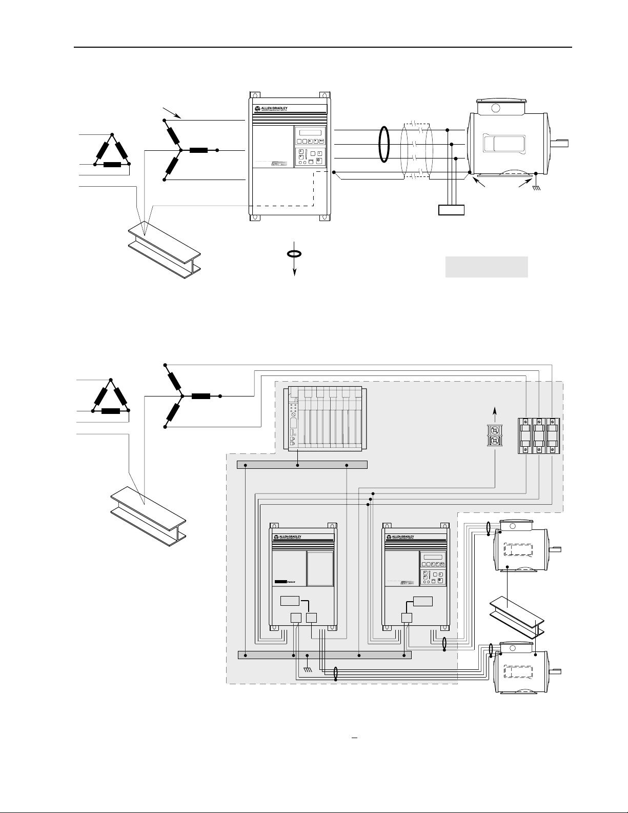
General Grounding
Installation/Wiring 2–13
Conduit/4-Wire Cable
Nearest
Building Structure Steel
R (L1)
S (L2)
ESC SEL
T (L3)
PE
RIO/DH+
or Analog
Common
Mode Core*
To Computer/Position Controller
(for TE shield ground, see "
Control and Signal Wiring"
Single-Point Grounding/Panel Layout
R (L1)
S (L2)
Common
Mode
U (T1)
Core*
V (T2)
JOG
W (T3)
PE/Gnd.
Shield
Motor Frame
PE
Ground per
Motor
Local Codes
Terminator*
* Options that can be
installed as needed.
)
To Nearest Building
Structure Steel
Nearest
Building Structure Steel
T (L3)
TE – Zero Volt Potential Bus
(Isolated from Panel)
PE Ground Bus
(Grounded to Panel)
For Programmable Controller
grounding recommendations,
refer to publication 1770-4.1
1336 FORCE 1336 PLUS
ESC SEL
JOG
Logic
PE TE
Logic
PE
Nearest Building
Structure Steel
Important: Grounding requirements will vary with the drives being used. Drives with True Earth (TE) terminals must have a zero potential bus, separate from potential
earth (PE) ground bus. Note that buses can be tied together at one point in the control cabinet or
brought back separately to the building ground grid (tied within 3 meters
(10 feet)).
Page 24
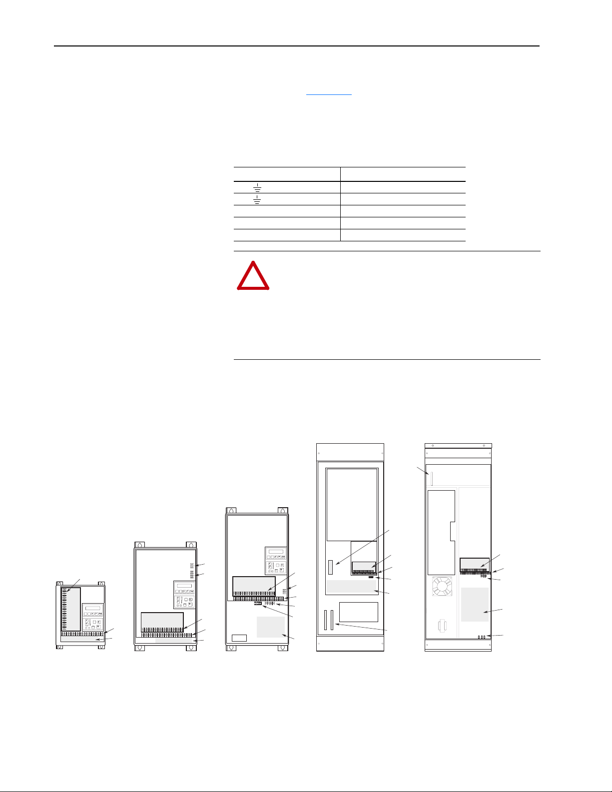
2–14 Installation/Wiring
Power Cabling Input and output power connections are performed through terminal
block, TB1 (see Figure 2.1
Important: For maintenance and setup procedures, the drive may be
operated without a motor connected.
Table 2.C
TB1 Signals
Terminal Description
PE Potential Earth Ground
TE True Earth Ground
R (L1), S (L2), T (L3) AC Line Input Terminals
+DC, -DC DC Bus Terminals
U (T1), V (T2), W (T3) Motor Connection
ATTENTION: The National Codes and standards (NEC,
!
VDE, BSI etc.) and local codes outline provisions for safely
installing electrical equipment. Installation must comply
with specifications regarding wire types, conductor sizes,
branch circuit protection and disconnect devices. Failure to
do so may result in personal injury and/or equipment damage.
for location).
TB1
Power Terminal Block
TB2
Control & Signal Wiring
TB3
Control Interface Option
TB4
24V DC Auxiliary Input
TB6
High Voltage DC Auxiliary Input
TB9
480 or 600V Auxiliary Output (F Frame Only)
TE
Control & Signal Shield Terminals
TB3
Option
Control Interface
TB1
Frames A1-A4
1
TB2
TB1
Control Interface
Option
TB1
Frames B, C
1
TB4
TB6
TB3
TB2
TB1
Figure 2.1
Terminal Block Locations
TB3
Control Interface
Option
TB1
Location
Frames D, E
TB4
TB2
TE
TB6
TB1
1
TB1 Location
1
Frame F
R, S, T
TB9
TB3
TB2
TE
TB1
Brake
Terminals
TB1
Location
Frame G
TB3
TB2
TE
U, V, W
& Brake
Terminals
PE
Ground
1
1
Refer to page 1–1 for frame reference classifications and Figure 2.2 for TB1 details.
Page 25

Installation/Wiring 2–15
Table 2.D
TB1 Specifications
Drive Frame
Size
Max./Min. Wire Size
mm2 (AWG)
1
A1-A4 (page 2–21) 5.3/0.8 (10/18) 1.81 (16)
B1 (page 2–21
B2 (page 2–21
C (page 2–21
D (page 2–22
E (page 2–22)
F (page 2–23
G (page 2–23
1
Wire sizes given are maximum/minimum sizes that TB1 will accept - these are not recommendations.Use
Copper wire only. Wire gauge requirements and recommendations are based on 75 degree C. Do not
reduce wire gauge when using higher temperature wire.
2
Applies to 30 kW (40 HP) 200-240V, 45 & 56 kW (60 & 75 HP) 380-480V, 56 kW (75 HP) 500-600V
drives only.
3
These configurations of TB1 are stud type terminations and require the use of lug type connectors to
terminate field installed conductors. Lug kits are available for use with these configurations. Wire size
used is determined by selecting the proper lug based on the drive catalog number. Refer to Table 2.E.
4
One TE terminal is present – Max./Min. Wire Size is the same as other terminals.
5
Two TE terminals are present – Max./Min. Wire Size is the same as the D Frame terminal block.
) 8.4/0.8 (8/18) 1.81 (16)
) 13.3/0.5 (6/20) 1.70 (15)
) 26.7/0.8 (3/18) 5.65 (50)
3, 4
)
3, 5
3
)
3
)
120.0/2.1 (4/0 /14)
67.4/2.1 (00/14)
2
253.0/2.1 (500 MCM/14) 10.00 (87)
303.6/2.1 (600 MCM/14) 23.00 (200)
303.6/2.1 (600 MCM/14) 23.00 (200)
Maximum Torque
N-m (lb.-in.)
6.00 (52)
6.00 (52)
Lug Kits
D, E, F and G Frame drives have stud type terminals and/or bus bars/
bolts that require standard “crimp type” connectors for cable termina-
tion. Connectors such as T & B Color-Keyed
lent) are recommended. The following table shows the lug selection
for one possible cable choice. Connectors for each installation should
be chosen based on desired cable sizes, the application requirements
and all applicable national, state and local codes. See the minimum/
maximum values for wire size per Tabl e 2.D
connectors (or equiva-
Page 26
2–16 Installation/Wiring
Table 2.E
Lug Selection
AC Input R, S, T/Output U, V, W and PE DC+/DC–
Drive Catalog
Number
Cable (per Phase)
Qty. mm2 (AWG)
T&B Part No.
Qty. Number
1336F-A040 (1) 53.5 (1/0) (8) 54153
1336F-A050 (1) 85.0 (3/0) (8) 54163
1336F-A060 (1) 107.2 (4/0) (8) 54168
1336F-A075 (2) 53.5 (1/0) (8) 54109T
3
Cable (per Phase)
Qty. mm2 (AWG)
1
(1) 13.3 (6) (2) 54135
1
(1) 13.3 (6) (2) 54135
1
(1) 13.3 (6) (2) 54135
(1) 33.6 (2) (2) 54109 (1) 21.2 (4) (1) 54139
(8) 54109B
1336F-A100 (2) 85.0 (3/0) (8) 54111T
(1) 42.4 (1) (2) 54148 (1) 33.6 (2) (1) 54142
(8) 54111B
1336F-A125 (2) 107.2 (4/0) (8) 54112T
(1) 67.4 (2/0) (2) 54110 (1) 33.6 (2) (1) 54142
(8) 54112B
1336F-B060 (1) 42.4 (1) (8) 54147
1336F-B075 (1) 53.5 (1/0) (8) 54153
1336F-B100 (1) 85.0 (3/0) (8) 54163
1336F-B125 (1) 107.2 (4/0) (8) 54168
1336F-BX150 (1) 107.2 (4/0) (8) 54168
1336F-B150 (2) 53.5 (1/0) (8) 54109T
1
(1) 8.4 (8) (2) 54131
1
(1) 13.3 (6) (2) 54135
1
(1) 13.3 (6) (2) 54135
1
(1) 26.7 (3) (2) 54147
1
(1) 26.7 (3) (2) 54147
(1) 33.6 (2) (2) 54110 (1) 21.2 (4) (1) 54139
(8) 54109B
1336F-B200 (2) 85.0 (3/0) (8) 54111T
(1) 42.4 (1) (2) 54148 (1) 26.7 (3) (1) 54142
(8) 54111B
1336F-B250 (2) 107.2 (4/0) (8) 54112T
(1) 67.4 (2/0) (2) 54110 (1) 33.6 (2) (1) 54142
(8) 54112B
1336F-BX250 (3) 53.5 (1/0) (24) 54109 (1) 67.4 (2/0) (2) 54110 NA NA
1336F-BP/BPR250 (3) 53.5 (1/0) (24) 54109 (1) 67.4 (2/0) (2) 54110 NA NA
1336F-B300 (3) 67.4 (2/0) (24) 54110 (1) 42.4 (1) (2) 54148 NA NA
1336F-BP/BPR300 (3) 67.4 (2/0) (24) 54110 (1) 42.4 (1) (2) 54148 NA NA
1336F-B350 (3) 85.0 (3/0) (24) 54111 (1) 42.4 (1) (2) 54148 NA NA
1336F-BP/BPR350 (3) 85.0 (3/0) (24) 54111 (1) 42.4 (1) (2) 54148 NA NA
1336F-B400 (3) 107.2 (4/0) (24) 54112 (1) 42.4 (1) (2) 54148 NA NA
1336F-BP/BPR400 (3) 107.2 (4/0) (24)54112 (1) 42.4 (1) (2) 54148 NA NA
1336F-B450 (3) 127.0 (250 MCM) (24) 54174 (1) 42.4 (1) (2) 54148 NA NA
1336F-BP/BPR450 (3) 127.0 (250 MCM) (24) 54174 (1) 42.4 (1) (2) 54148 NA NA
1336F-B500 (3) 152.0 (300 MCM) (24) 54179 (1) 53.5 (1/0) (2) 54109 NA NA
1336F-B600 (3) 152.0 (300 MCM) (24) 54179 (1) 53.5 (1/0) (2) 54109 NA NA
1
1336F-C075 (1) 33.6 (2) (8) 54142
1336F-C100 (1) 53.5 (1/0) (8) 54153
1336F-C125 (1) 67.4 (2/0) (8) 54158
(1) 13.3 (6) (2) 54135
1
(1) 13.3 (6) (2) 54135
1
(1) 26.7 (3) (2) 54147
1336F-C150 (1) 107.2 (4/0) (8) 54111 (1) 42.4 (1) (2) 54148 (1) 13.3 (6) (1) 54135
1336F-C200 (2) 67.4 (2/0) (8) 54110T
(1) 42.4 (1) (2) 54148 (1) 26.7 (3) (1) 54142
(8) 54110B
1336F-C250 (2) 85.0 (3/0) (8) 54111T
(1) 67.4 (2/0) (2) 54110 (1) 26.7 (3) (1) 54142
(8) 54111B
1336F-CX300 (3) 85.0 (3/0) (16) 54111
1336F-C300 (3) 85.0 (3/0) (16) 54111 NA NA
1336F-C350 (3) 53.5 (1/0) (24)54109 NA NA
1336F-C400 (3) 67.4 (2/0) (24) 54110 NA NA
1336F-C450 (3) 85.0 (3/0) (24) 54111 NA NA
1336F-C500 (3) 107.2 (4/0) (24)54112 NA NA
1336F-C600 (3) 127.0 (250 MCM) (24) 54174 NA NA
1
5/16” Stud. All other studs are 3/8”.
2
Lugs shown for DC+/– are based on dynamic brake sizing of 50% of (motor rating X 1.25). Select proper lugs based on required braking torque. Refer to 1336-5.64 or
1336-5.65 for additional information.
3
T & B COLOR-KEYED Connectors require T & B WT117 or TBM-6 Crimper tool or equivalent. Lugs should be crimped according to manufacturer’s tool instructions.
If required, Rockwell Automation can supply lug kits for lugs shown above. Kits do not include crimping tools. Consult factory for kit information.
2
Consult Factory
T&B Part No.
Qty. Number
1
1
1
1
1
1
1
1
1
1
1
TE
3
Cable (per Phase)
Qty. mm2 (AWG)
(1) 13.3 (6) (1) 54135
(1) 13.3 (6) (1) 54135
(1) 21.2 (4) (1) 54139
(1) 13.3 (6) (1) 54135
(1) 13.3 (6) (1) 54135
(1) 13.3 (6) (1) 54135
(1) 21.2 (4) (1) 54139
(1) 21.2 (4) (1) 54139
(1) 8.4 (8) (1) 54131
(1) 13.3 (6) (1) 54135
(1) 13.3 (6) (1) 54135
NA NA
T&B Part No.
Qty. Number
1
1
1
1
1
1
1
1
1
1
1
1
1
1
1
1
1
1
1
1
3
Page 27

Installation/Wiring 2–17
Motor Cables
A variety of cable types are acceptable for drive installations. For
many installations, unshielded cable is adequate, provided it can be
separated from sensitive circuits. As an approximate guide, allow a
spacing of 0.3 meters (1 ft.) for every 10 meters (32.8 ft.) of length. In
all cases, long parallel runs must be avoided. Do not use cable with an
insulation thickness less than or equal to 15 mils (0.4 mm/0.015 in.).
The cable should be 4-conductor with the ground lead being connected directly to the drive ground terminal (PE) and the motor frame
ground terminal. See table below.
Unshielded
THHN, THWN or similar wire is acceptable for drive installation in
dry environments provided adequate free air space and/or conduit fill
rates limits are provided. Do not use THHN or similarly coated
wire in wet areas. Any wire chosen must have a minimum insulation
thickness of 15 mils and should not have large variations in insulation
concentricity.
Shielded/Armored Cable
Shielded cable is recommended if sensitive circuits or devices are
connected or mounted to the machinery driven by the motor (see
table).
Recommended Shielded Wire
Location Rating/Type Description
Standard
(Option 1)
Standard
(Option 2)
Class I & II;
Division I & II
600V, 90° C (194°F)
XHHW2/RHW-2
Anixter B209500-
B209507, Belden 29501-
29507, or equivalent
Tray rated 600V, 90° C
(194° F) RHH/RHW-2
Anixter OLF-7xxxxx or
equivalent
Tray rated 600V, 90° C
(194° F) RHH/RHW-2
Anixter 7V-7xxxx-3G or
equivalent
• Four tinned copper conductors with XLP insulation.
• Copper braid/aluminum foil combination shield and
tinned copper drain wire.
• PVC jacket.
• Three tinned copper conductors with XLPE insulation.
• 5 mil single helical copper tape (25% overlap min.)
with three bare copper grounds in contact with shield.
• PVC jacket.
• Three bare copper conductors with XLPE insulation
and impervious corrugated continuously welded alu-
minum armor.
• Black sunlight resistant PVC jacket overall.
• Three copper grounds on #10 AWG and smaller.
Conduit
If metal conduit is preferred for cable distribution, the following
guidelines must be followed.
• Drives are normally mounted in cabinets and ground connections
are made at a common ground point in the cabinet. Normal installation of conduit provides grounded connections to both the motor
frame ground (junction box) and drive cabinet ground. These
ground connections help minimize interference. This is a noise
reduction recommendation only, and does not affect the requirements for safety grounding (refer to pages 2–11
and 2–12).
Page 28
2–18 Installation/Wiring
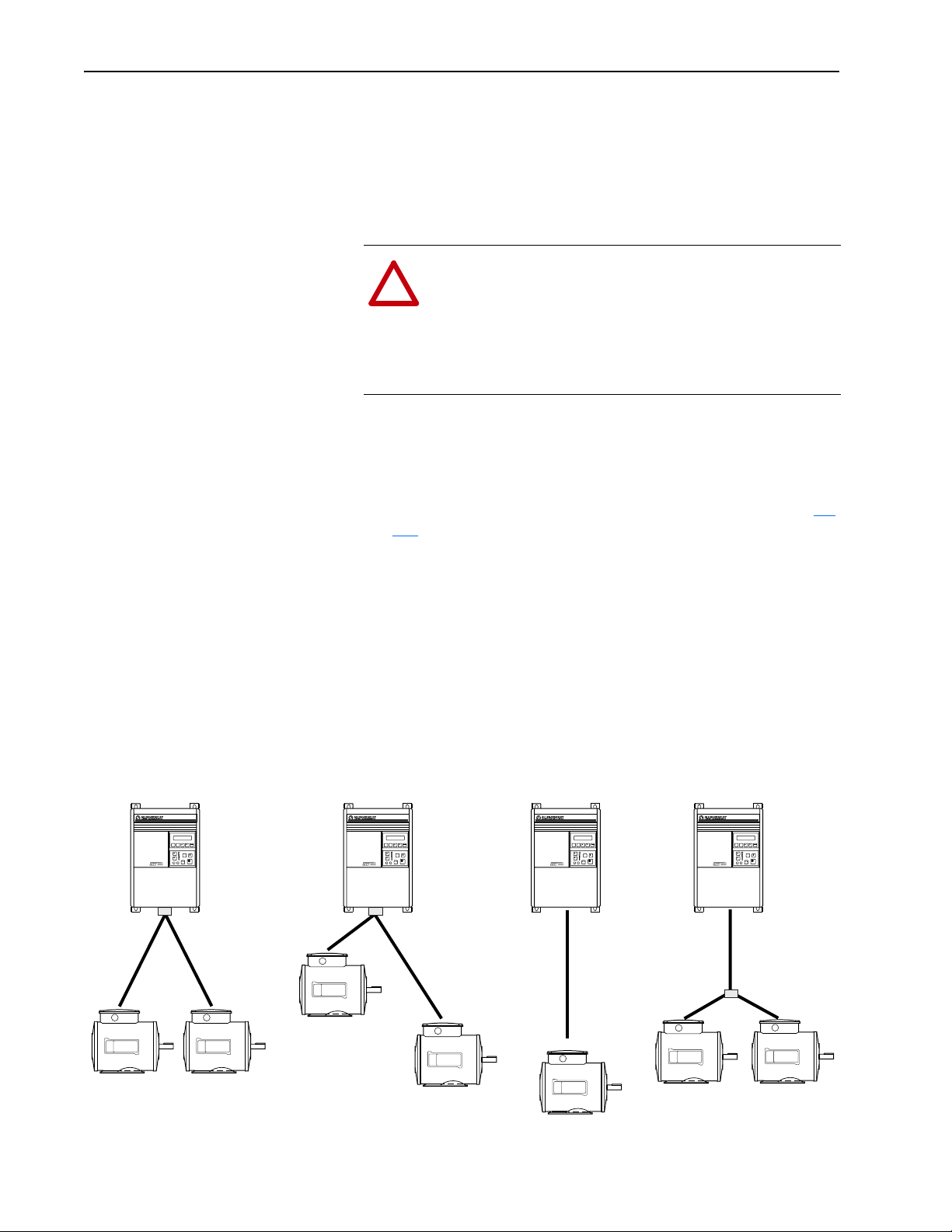
• No more than three sets of motor leads can be routed through a single conduit. This will minimize “cross talk” that could reduce the
effectiveness of the noise reduction methods described. If more
than three drive/motor connections per conduit are required,
shielded cable as described above must be used. If practical, each
conduit should contain only one set of motor leads.
ATTENTION: To avoid a possible shock hazard caused by
!
induced voltages, unused wires in the conduit must be
grounded at both ends. For the same reason, if a drive sharing a conduit is being serviced or installed, all drives using
this conduit should be disabled. This will eliminate the possible shock hazard from “cross coupled” drive motor leads.
Motor Lead Lengths
Installations with long cables to the motor may require the addition of
output reactors or cable terminators to limit voltage reflections at the
motor. Excessive cable charging current can also reduce the amount
of current available to produce rated motor torque. Refer to Tables 2.F
and 2.G
for the maximum cable length allowed for various installation techniques. Shaded distances are restricted by cable capacitance
charging current. The figure below demonstrates how total cable
length is calculated. Failure to follow these guidelines can result in
poor motor performance and nuisance drive overcurrent or overload
tripping. For installations that exceed the recommended maximum
lengths listed, contact the factory.
Please note that the cable lengths shown are guidelines. Your application may be restricted to a shorter cable length due to wire type, wire
placement, line reactor and type of motor.
How to Measure Motor Cable Lengths Limited by Capacitance
ESC SEL
JOG
91.4 (300)
91.4 (300)
All examples represent motor cable length of 189.2 meters (600 feet).
15.2 (50)
ESC SEL
JOG
167.6 (550)
ESC SEL
JOG
182.9 (600)
ESC SEL
JOG
152.4 (500)
15.2 (50) 15.2 (50)
Page 29
Installation/Wiring 2–19
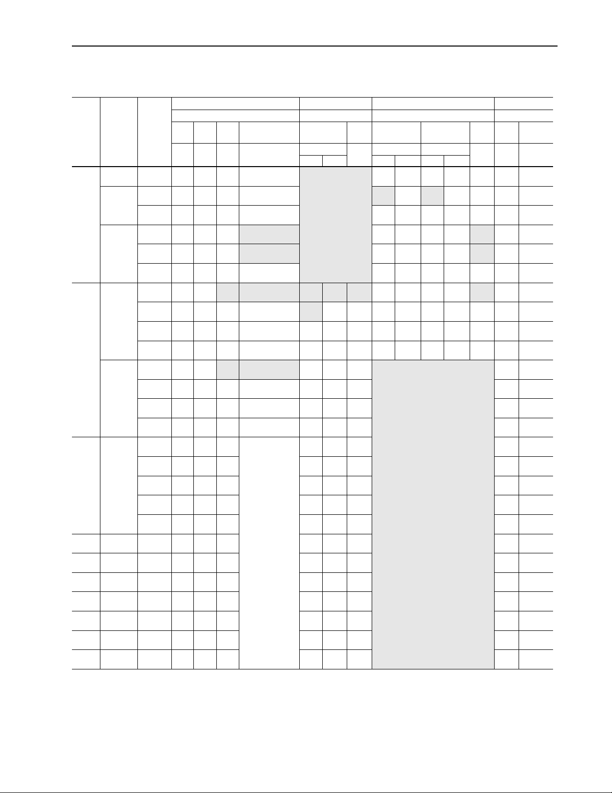
Table 2.F
Maximum Motor Cable Length Restrictions in meters (feet) - 380V-480V Drives
Any
CableShld.
182.9
(600)
182.9
(600)
182.9
(600)
182.9
(600)
182.9
(600)
182.9
(600)
182.9
(600)
182.9
(600)
182.9
(600)
182.9
(600)
182.9
(600)
182.9
(600)
182.9
(600)
182.9
(600)
182.9
(600)
182.9
(600)
182.9
(600)
182.9
(600)
182.9
(600)
182.9
(600)
182.9
(600)
182.9
(600)
182.9
(600)
182.9
(600)
182.9
(600)
182.9
(600)
2
No External Devices w/1204-TFB2 Term. w/1204-TFA1 Terminator Reactor at Drive
Motor Motor Motor Motor
1600V or
A B 1329
Drive
Frame
Drive kW
(HP)
Motor kW
(HP)
Any
Cable
A1 0.37 (0.5) 0.37 (0.5) 12.2
(40)
0.75 (1) 0.75 (1) 12.2
(40)
0.37 (0.5) 12.2
(40)
1.2 (1.5) 1.2 (1.5) 12.2
(40)
0.75 (1) 12.2
(40)
0.37 (0.5) 12.2
(40)
A2 1.5 (2) 1.5 (2) 7.6
(25)
1.2 (1.5) 7.6
(25)
0.75 (1) 7.6
(25)
0.37 (0.5) 7.6
(25)
2.2 (3) 2.2 (3) 7.6
(25)
1.5 (2) 7.6
(25)
0.75 (1) 7.6
(25)
0.37 (0.5) 7.6
(25)
A3 3.7 (5) 3.7 (5) 7.6
(25)
2.2 (3) 7.6
(25)
1.5 (2) 7.6
(25)
0.75 (1) 7.6
(25)
0.37 (0.5) 7.6
(25)
A4 5.5-15
(7.5-20)
B 11-22
(15-30)
C 30-45
(X40-X60)
D 45-112
(60-X150)
E 112-187
(150-250)
F 187-336
(250-450)
G 187-448
(X250-600)
5.5-15
(7.5-20)
11-22
(15-30)
30-45
(40-60)
45-112
(60-150)
112-187
(150-250)
187-336
(250-450)
187-448
(250-600)
7.6
(25)
7.6
(25)
7.6
(25)
12.2
(40)
12.2
(40)
18.3
(60)
18.3
(60)
Any
Cable
33.5
(110)
33.5
(110)
33.5
(110)
33.5
(110)
33.5
(110)
33.5
(110)
12.2
(40)
12.2
(40)
12.2
(40)
12.2
(40)
12.2
(40)
12.2
(40)
12.2
(40)
12.2
(40)
12.2
(40)
12.2
(40)
12.2
(40)
12.2
(40)
12.2
(40)
12.2
(40)
12.2
(40)
12.2
(40)
30.5
(100)
53.3
(175)
53.3
(175)
53.3
(175)
1329R/L (1850V) A or B 1329 A B 1329 A B or 1329
Any
Any
Cable
Cable
91.4
91.4
(300)
(300)
91.4
91.4
(300)
(300)
91.4
91.4
(300)
(300)
91.4
91.4
(300)
(300)
91.4
91.4
(300)
(300)
114.3
121.9
(375)
(400)
91.4
91.4
(300)
(300)
114.3
182.9
(375)
(600)
114.3
182.9
(375)
(600)
114.3
182.9
(375)
(600)
91.4
91.4
(300)
(300)
114.3
182.9
(375)
(600)
114.3
182.9
(375)
(600)
114.3
182.9
(375)
(600)
114.3
182.9
(375)
(600)
114.3
Contact factory for
(375)
advice on cable
114.3
lengths over 182.9
(375)
(600).
114.3
(375)
114.3
(375)
114.3
(375)
114.3
(375)
114.3
(375)
114.3
(375)
114.3
(375)
114.3
(375)
114.3
(375)
6
3
Unshld. Shld.3Unshld. Shld.3Unshld.
Use 1204-TFA1 30.5
91.4
91.4
(300)
(300)
91.4
182.9
(300)
(600)
182.9
182.9
(600)
(600)
182.9
182.9
(600)
(600)
182.9
182.9
(600)
(600)
182.9
182.9
(600)
(600)
182.9
182.9
(600)
(600)
182.9
182.9
(600)
(600)
182.9
182.9
(600)
(600)
182.9
182.9
(600)
(600)
182.9
182.9
(600)
(600)
182.9
182.9
(600)
(600)
182.9
182.9
(600)
(600)
182.9
182.9
(600)
(600)
182.9
182.9
(600)
(600)
182.9
182.9
(600)
(600)
182.9
182.9
(600)
(600)
182.9
182.9
(600)
(600)
182.9
182.9
(600)
(600)
182.9
182.9
(600)
(600)
Cable Type
Cable Type Cable Type
Any
Cable
30.5
61.0
(100)
(200)
30.5
30.5
(100)
(100)
61.0
(100)
(200)
30.5
30.5
(100)
(100)
30.5
30.5
(100)
(100)
30.5
30.5
(100)
(100)
91.4
30.5
(100)
30.5
(100)
30.5
(100)
30.5
(100)
30.5
(100)
30.5
(100)
30.5
(100)
30.5
(100)
(300)
182.9
(600)
182.9
(600)
182.9
(600)
182.9
(600)
182.9
(600)
182.9
(600)
182.9
(600)
182.9
(600)
182.9
(600)
182.9
(600)
182.9
(600)
182.9
(600)
182.9
(600)
182.9
(600)
182.9
(600)
182.9
(600)
182.9
(600)
182.9
(600)
182.9
(600)
30.5
61.0
(100)
(200)
30.5
30.5
(100)
(100)
30.5
61.0
(100)
(200)
61.0
61.0
(200)
(200)
61.0
61.0
(200)
(200)
61.0
61.0
(200)
(200)
91.4
61.0
(300)
(200)
91.4
61.0
(300)
(200)
91.4
61.0
(300)
(200)
91.4
61.0
(300)
(200)
Use 1204-TFB2
Any
Cable
91.4
(300)
91.4
(300)
91.4
(300)
91.4
(300)
91.4
(300)
121.9
(400)
91.4
(300)
182.9
(600)
182.9
(600)
182.9
(600)
Any
Cable
22.9
(75)
22.9
(75)
22.9
(75)
22.9
(75)
22.9
(75)
22.9
(75)
22.9
(75)
22.9
(75)
22.9
(75)
22.9
(75)
22.9
(75)
22.9
(75)
22.9
(75)
22.9
(75)
22.9
(75)
22.9
(75)
22.9
(75)
22.9
(75)
22.9
(75)
24.4
(80)
24.4
(80)
76.2
(250)
61.0
(200)
182.9
(600)
182.9
(600)
182.9
(600)
Type A Motor Characteristics: No phase paper or misplaced phase paper, lower quality insulation systems, corona inception voltages between 850 and 1000 volts.
Type B Motor Characteristics: Properly placed phase paper, medium quality insulation systems, corona inception voltages between 1000 and 1200 volts.
1329R/L Motors: These AC variable speed motors are “Control-Matched” for use with Allen-Bradley Drives. Each motor is designed to meet or exceed
the requirements of the Federal Energy Act of 1992. All 1329R/L motors are optimized for variable speed operation and include premium
inverter grade insulation systems which meet or exceed NEMA MG1. Part 31.40.4.2.
1
Page 30

2–20 Installation/Wiring
Table 2.G
Maximum Motor Cable Length Restrictions in meters (feet) - 500V-600V Drives
No External Devices w/1204-TFB2 Terminator w/1204-TFA1 Terminator Reactor at Drive
Motor Motor Motor Motor
1329R/L
5
AB
Any
Any
Cable
Cable
Drive
Frame
Drive kW
(HP)
Motor kW
(HP)
AB
Any
Any
Cable
Cable
Motors
Any
Cable
A4 0.75 (1) 0.75 (1) NR NR NA NR 182.9
(600)
0.37 (0.5) NR NR
NA NR 182.9
(600)
1.5 (2) 1.5 (2) NR NR
NA NR 182.9
(600)
1.2 (1.5) NR NR
NA NR 182.9
(600)
0.75 (1) NR NR 182.9
0.37 (0.5) NR NR 182.9
2.2 (3) 2.2 (3) NR NR
(600)
(600)
NA NR 182.9
NR 182.9
(600)
NR 182.9
(600)
(600)
1.5 (2) NR NR
NA NR 182.9
(600)
0.75 (1) NR NR 182.9
0.37 (0.5) NR NR 182.9
3.7 (5) 3.7 (5) NR NR
(600)
(600)
NA NR 182.9
NR 182.9
(600)
NR 182.9
(600)
(600)
2.2 (3) NR NR
NA NR 182.9
(600)
5.5-15
(7.5-20)
C 18.5-45
(25-60)
D 56-93
(75-125)
E 112-224
(150-X300)
F 261-298
(350-400)
G 224-448
(300-600)
1.5 (2) NR NR 182.9
(600)
0.75 (1) NR NR 182.9
(600)
0.37 (0.5) NR NR 182.9
(600)
5.5-15
(7.5-20)
18.5-45
(25-60)
56-93
(75-125)
112-224
(150-X300)
261-298
(350-400)
224-448
(300-600)
NR 9.1
(30)
NR 9.1
(30)
NR 9.1
(30)
NR 9.1
(30)
NR 9.1
(30)
NR 9.1
(30)
182.9
(600)
182.9
(600)
182.9
(600)
182.9
(600)
182.9
(600)
182.9
(600)
NR 182.9
(600)
NR 182.9
(600)
NR 182.9
(600)
91.4
182.9
(300)
(600)
91.4
182.9
(300)
(600)
91.4
182.9
(300)
(600)
91.4
182.9
(300)
(600)
91.4
182.9
(300)
(600)
91.4
182.9
(300)
(600)
1600V or
1329R/L
(1850V)5AB
Any
Cable
335.3
Any
Cable
NR 61.0
(1100)
335.3
NR 61.0
(1100)
335.3
NR 61.0
(1100)
335.3
NR 61.0
(1100)
335.3
NR 61.0
(1100)
335.3
NR 61.0
(1100)
335.3
NR 61.0
(1100)
335.3
NR 61.0
(1100)
335.3
NR 61.0
(1100)
335.3
NR 61.0
(1100)
335.3
NR 61.0
(1100)
335.3
NR 61.0
(1100)
335.3
NR 61.0
(1100)
335.3
NR 61.0
(1100)
335.3
NR 61.0
(1100)
182.9
NR 61.0
(600)
182.9
NR 61.0
(600)
182.9
NR 61.0
(600)
182.9
NR 61.0
(600)
182.9
NR 61.0
(600)
182.9
NR 61.0
(600)
1600V or
1329R/L
(1850V)5AB
Any
Any
Cable
Cable
182.9
(200)
(600)
182.9
(200)
(600)
182.9
(200)
(600)
182.9
(200)
(600)
182.9
(200)
(600)
182.9
(200)
(600)
182.9
(200)
(600)
182.9
(200)
(600)
182.9
(200)
(600)
182.9
(200)
(600)
182.9
(200)
(600)
182.9
(200)
(600)
182.9
(200)
(600)
182.9
(200)
(600)
182.9
(200)
(600)
182.9
(200)
(600)
182.9
(200)
(600)
182.9
(200)
(600)
182.9
(200)
(600)
182.9
(200)
(600)
182.9
(200)
(600)
Any
Cable
30.5
(100)
30.5
(100)
61.0
(200)
182.9
(600)
182.9
(600)
182.9
(600)
NR = Not Recommended
NA = Not Available at time of printing
1
Values shown are for 480V nominal input voltage, drive carrier frequency of 2 kHz and ambient temperature at the motor of 40 degrees C. Consult factory regarding
operation at carrier frequencies above 2 kHz. Multiply values by 0.85 for high line conditions. For input voltages of 380, 400 or 415V AC, multiply the table values by
1.25, 1.20 or 1.15, respectively.
2
A 3% reactor reduces motor and cable stress but may cause a degradation of motor waveform quality. Reactors must have a turn-turn insulation rating of 2100 volts
or higher.
3
Includes wire in conduit.
4
Values shown are for nominal input voltage and drive carrier frequency of 2 kHz. Consult factory regarding operation at carrier frequencies above 2 kHz. Multiply values
by 0.85 for high line conditions.
5
When used on 600V systems, 1329R/L motors have a corona inception voltage rating of approximately 1850V.
6
These distance restrictions are due to charging of cable capacitance and may vary from application to application.
2
1600V or
1329R/L
(1850V)
Any
Any
Cable
Cable
Not
Recommended
91.4
182.9
(300)
(600)
91.4
182.9
(300)
(600)
91.4
182.9
(300)
(600)
182.9
182.9
(600)
(600)
182.9
182.9
(600)
(600)
182.9
182.9
(600)
(600)
4
5
Page 31

A1-A3
Frame
Figure 2.2
Terminal Block TB1
Installation/Wiring 2–21
A4
Frame
200-240V, 0.37-3.7 kW (0.5-5 HP) Terminal Designations
380-480V, 0.37-3.7 kW (0.5-5 HP) Terminal Designations
To Motor
Required
Input Fusing
R
(L1)S(L2)T(L3)
1
1
Required Branch
Circuit Disconnect
AC Input Line
B1
DC+DC
Dynamic Brake
Option
Frame
U
(T1)V(T2)W(T3)
–
To Motor
200-240V, 5.5 kW (7.5 HP) Terminal Designations
380-480V, 11 kW (15 HP) Terminal Designations
R
PE PE
To Motor
DC
DC
–
+
Dynamic Brake
(L1)S(L2)T(L3)
1
Required Branch
Circuit Disconnect
AC Input Line
U
(T1)V(T2)W(T3)
To Motor
Required
Input Fusing
200-240V, 15-22 kW (20-30 HP) Terminal Designations
380-480V, 30-45 kW (40-60 HP) Terminal Designations
500-600V, 18.5-45 kW (25-60 HP) Terminal Designations
380-480V, 5.5-15 kW (7.5-20 HP) Terminal Designations
500-600V, 0.75-15 kW (1-20 HP) Terminal Designations
GRD GRDGRD GRD R
To Motor
1
Required
Input Fusing
(L1)S(L2)T(L3)
1
Required Branch
Circuit Disconnect
AC Input Line
DC
+
COM
DC Input Line
Dynamic Brake
DC
2
U
BRK
(T1)V(T2)W(T3)
–
–
To Motor
Important: A brake malfunction
will occur if the Dynamic Brake is
connected to "DC – COM"
B2
Frame
200-240V, 7.5-11 kW (10-15 HP) Terminal Designations
380-480V, 15-22 kW (20-30 HP) Terminal Designations
R
PE PE
1
To Motor
DC
DC
–
+
Dynamic Brake
Required
Input Fusing
(L1)S(L2)T(L3)
1
1
Required Branch
Circuit Disconnect
AC Input Line
U
(T1)V(T2)W(T3)
To Motor
PE
GRD
PE
GRDDC+
To Motor
DC
–
Dynamic Brake
1
Required
Input Fusing
S
R
(L2)
(L1)
1
Required Branch
Circuit Disconnect
AC Input Line
T
(L3)
U
(T1)
V
(T2)
To Motor
W
(T3)
C
Frame
1
User supplied.
2
Terminal located separately on Series A Drives.
Page 32

2–22 Installation/Wiring
D
Frame
200-240V, 30-45 kW (40-60 HP) Terminal Designations
380-480V, 45-112 kW (60-150 HP) Terminal Designations
500-600V, 56-93 kW (75-125 HP) Terminal Designations
DC –
R
(L1)
DC +
Brake
S
(L2)
PE PE TE
Brake
T
(L3)
U
(T1)
To Motor
V
(T2)
W
(T3)
E
Frame
TE
See Appendix B for detailed Dimensions.
To Motor
1
Required
Input Fusing
1
Required Branch
Circuit Disconnect
AC Input Line
See Appendix B for detailed Dimensions.
200-240V, 56-93 kW (75-125 HP) Terminal Designations
380-480V, 112-187 kW (150-250 HP) Terminal Designations
500-600V, 112-224 kW (150-300 HP) Terminal Designations
–DC+DC PE PE R-L1 S-L2 T-L3 U-M1 V-M2 W-M3
BUS INPUT OUTPUT
To Motor
Required
Input Fusing
1
1
Required Branch
Circuit Disconnect
AC Input Line
To Motor
1
User supplied.
Page 33

Installation/Wiring 2–23
TB1 F-G
380-480V, 187-336 kW (250-450 HP) Terminal Designations
500-600V, 261-336 kW (350-450 HP) Terminal Designations
F
Frame
DC –
Brake
DC +
Brake
R-L1
1
Required Branch
Circuit Disconnect
AC Input Line
1336F-BPR and CPR Drives are supplied with a separately
mounted, pre-wired DC Bus Inductor (see Appendix B). If the
cable length between the choke and drive is not sufficient, longer
cables (same size & type) can be used. Cable routing must also
T-L3
S-L2
Input Fusing
(Supplied)
be considered when mounting the choke.
U-M1PE
V-M2
To Motor
380-480V, 187-448 kW (250-600 HP) Terminal Designations
500-600V, 224-448 kW (300-600 HP) Terminal Designations
W-M3
typical terminal
G
Frame
Required
Input Fusing
1
User supplied.
T
(L3)
1
1
Required Branch
Circuit Disconnect
AC Input Line
S
R
(L2)
(L1)
S
T
typical terminal layout
(located at top of drive)
Brake terminals are located on the
DC Bus Inductor behind the "U" terminal
(access from the right side of the chassis)
to +DC Terminal
U
(M1)
V
(M2)
To Motor
W
(M3)
on Brake
to –DC Terminal
on Brake
R
U
V
(located at bottom of drive)
W
Page 34

2–24 Installation/Wiring
Control and Signal Wiring General Wiring Information
General requirements for analog signal wire include: stranded copper
0.750-0.283 mm
wire, 300V minimum insulation rating and a temperature rating
suitable for the application (not less than 60 degrees C.) The recommended signal (analog I/O) wire is:
• Belden 8760/9460 (or equiv.) – 0.750 mm2(18AWG), twisted pair, shielded.
• Belden8770 (or equiv.) – 0.750 mm2(18AWG), 3 conductor, shielded for remote pot only.
The recommended wire for encoder or pulse inputs/outputs is:
• Lengths less than or equal to 30 meters (98 feet)
Belden 9730 (or equiv.) – 0.196 mm2(24AWG), individually shielded.
• Lengths greater than 30 meters (98 feet)
Belden 9773 (or equiv.) – 0.750 mm2(18AWG), twisted pair, shielded.
Signal Connections
If the drive control connections are to be linked to an electronic
circuit or device, the common or 0V line should, if possible, be
grounded at the device (source) end only.
2
(18-22 AWG), twisted-pair, 100% shield with drain
Important: Signal Common - User speed reference signals are
terminated to logic common at TB2, terminal 5. This puts
the negative (or common) side of these signals at earth
ground potential. Control schemes must be examined for
possible conflicts with this type of grounding scheme.
Shield Termination - TE (True Earth)
The TE terminal block (not available on A Frame drives) provides a
terminating point for signal wiring shields. A Frame drives can use
TB2, terminal 5 for signal wiring shield termination. Refer to Figure
2.1 for location.
The maximum and minimum wire size accepted by this block is 2.1
and 0.30 mm
2
(14 and 22 AWG). Maximum torque is 1.36 N-m (12
lb.-in.). Use Copper wire Only and always separate control and power
cabling.
Cable Routing
If unshielded cable is used, signal circuits should not run parallel to
motor cables or unfiltered supply cables with a spacing less than 0.3
meters (1 foot). Cable tray metal dividers or separate conduit should
be used.
Important: When user installed control and signal wiring with an
insulation rating of less than 600V is used, this wiring
must be routed inside the drive enclosure and separated
from any other wiring and/or uninsulated live parts.
Page 35

Installation/Wiring 2–25
Terminal Block TB2
TB2 is located at the bottom of the Main Control Board. A Frame
drives have 18 positions. Remaining frame sizes have 22 positions.
The maximum and minimum wire size accepted by TB2 is 2.1 and
0.30 mm
1.36 N-m (12 lb.-in.). Use Copper wire only. See Figure 2.1
2
(14 and 22 AWG). Maximum torque for all terminals is
.
Terminal Block TB3
The Control Interface Option provides a means of interfacing various
signals and commands to the 1336
Several different versions of the option are available:
• L4 Contact Closure Interface
• L4E Contact Closure Interface
• L7E Contact Closure Interface
for use with encoder loss detection.
• L5 +24VAC/DC Interface.
• L5E +24VAC/DC Interface with Encoder Feedback Inputs.
• L8E +24VAC/DC Interface with Encoder Feedback Inputs
for use with encoder loss detection.
• L6 115VAC Interface.
• L6E 115VAC Interface with Encoder Feedback Inputs.
• L9E 115VAC Interface with Encoder Feedback Inputs
for use with encoder loss detection.
1
Uses internal +5V DC supply.
PLUS II by using contact closures.
1
.
1
with Encoder Feedback Inputs.
1
with Encoder Feedback Inputs
The user inputs are connected to the option board through TB3 (see
Figure 2.1
for location). The L4, L5 and L6 options each have nine
control inputs. The function of each input must be selected through
programming as explained later in this section. The L4E through L9E
options are similar to L4, L5 and L6 with the addition of encoder
feedback inputs. In addition, the L7E, L8E and L9E options allow
encoder loss detection. Refer to Appendix A for further information.
The maximum and minimum wire size accepted by TB3 is 2.1 and
0.30 mm
2
(14 and 22 AWG). Recommended torque for all terminals
is 0.90-1.13 N-m (8-10 lb.-in.). Use Copper wire only.
Digital Inputs Digital inputs are connected at TB3.
Input Mode Select
A number of combinations are available by first programming
[Input Mode] to the desired control scheme (i.e. 2 wire, 3 wire or
Status). The remaining inputs can then be configured by programming [TB3 Term 22 Sel] through [TB3 Term 28 Sel]. Refer to the
Digital I/O parameter group in Chapter 6 for programming
information.
Page 36

2–26 Installation/Wiring
Figure 2.3
Digital I/O Default Settings – TB3
2
Status
(Factory Default)
Input Mode (Start/Stop Functions Only)
2-Wire Control
Single-Source Control
3-Wire Control
Single-Source Reversing
Input 1
Input 2
Common
Input 3
Input 4
Input 5
Common
Input 6
Input 7
Input 8
Common
Input 9
Encoder B
Encoder NOT A
Encoder NOT B
Encoder A
+12V (200mA max.)
Encoder Common
19
20
21
22
23
24
25
26
27
28
29
30
31
32
33
34
35
36
Status
Stop/Fault Reset
3
Status Only
Default Mode
shown at right
is not active
when
[Input Mode]
is set to "Status"
3
Enable
Included on
L4E through L9E
Only
Run Forward
Stop/Fault Reset
Start
3
Stop/Fault Reset
3
Factory Default Inputs
Common
4
Rev/For
(Programmable)
Jog (Programmable)
3
(Programmable)
Auxiliary
Common
Speed Select 3
Speed Select 2
Speed Select 1
1
(Programmable)
1
(Programmable)
1
(Programmable)
Common
3
Enable
1
See
Speed Select
2
If this mode is selected, the status of all inputs can
be read at the [Input Status] parameter. However,
only “Stop/Fault Reset” and “Enable” will have
control function.
3
These inputs must be present (reprogram if
necessary) before drive will start.
4
Bit 0 of [Direction Mask] must = 1 to allow TB3
direction change/bipolar operation.
5
Requires "2 Wire" control selection for [Input
Mode].
6
[TB3 Term 22] must be programmed to "Run
Reverse."
(Not Programmable)
Table.
3-Wire Control Example2-Wire Control Example
19
20
21
22
Run Forward
Stop/Fault Reset
Common Common
5
3
6
19
20
21
22
Start
Stop
Rev/For (Default)Run Reverse
A hazard of personal injury from automatic restart exists with 2-wire control.
2-wire control uses maintained Run contacts that act as both Run (closed)
!
and Stop (open) devices. Opening the Stop contact (terminal 20) will stop the
drive. If this contact is reclosed, any fault will be reset. If a valid Start
command is still present, the drive will restart. Only use 2-wire control for
applications outlined in NFPA79, "Under Voltage Protection."
If a 3-wire device (i.e. HIM) is also used, pressing the HIM Stop key will also
stop the drive. Releasing the Stop key will clear any faults that are present,
but the drive will not restart without cycling the Start contact.
Page 37

Installation/Wiring 2–27
Available Functions for Inputs 3 through 8
A variety of combinations made up of the following inputs are available.
Input Description
st
and 2nd Accel
1
1st and 2nd Decel
st/2nd
Accel/Decel Allows selection of the accel or decel time used by the drive. 1=2nd, 0=1st
1
Auxiliary Faults the drive via external devices (i.e. motor thermoswitch, O.L. relays, etc.). Opening this contact will
Clear Fault If drive has faulted, closing this input will clear the fault.
Digital Pot (MOP) Up/
Down
Forward Closing these inputs (Forward or Reverse) commands the corresponding direction. If both inputs are open
Jog Closing this input starts the drive and causes it to run at programmed jog frequency. Opening this input
Local Control Closing this input gives exclusive control of drive logic to the inputs at terminal block TB3. No other
Rev/For Available only with three-wire control - Closing this input commands reverse direction and opening this
Reverse See “Forward” above.
PI Enable Enables the output of the process PI loop.
PI Reset Opening this input clamps the process PI integrator value at zero. Closing this input allows the integrator
Run Reverse Available Only with two-wire control - Closing this input issues both a start command and a reverse com-
Speed Select 1, 2, 3 These inputs choose the frequency command source for the drive. See following pages for details.
Stop Type Closing this input selects the stop mode in [Stop Select 2] as the method of stopping when a stop com-
Sync Normally wired to multiple drives – When the Sync input is low, the drive operates normally. When the
Traverse Setting this input low disables the traverse function. When the input is high, the traverse function will be
Closing these inputs will command the corresponding accel or decel rate. If both inputs are open or both
are closed, the current rate is maintained.
Input 1st2
No Command 0 0
Accel/Decel 1 0 1
Accel/Decel 2 1 0
fault (F02 - Aux Fault) the drive and shut the output off, ignoring the programmed stop mode.
These inputs increase (up) or decrease (down) the drive commanded frequency when MOP (Motor Oper-
ated Potentiometer) is chosen as the frequency command source. The rate of increase/decrease is pro-
grammable.
or both are closed, the current direction is maintained.
stops the drive using the programmed stop mode.
devices may issue logic commands (excluding Stop) to the drive.
input commands forward direction.
to continue to operate.
mand to the drive. Opening the input issues a stop command to the drive.
mand is issued. Opening this input selects the stop mode in [Stop Select 1] as the method of stopping.
input is high, the speed of the drive will be held constant and the speed command will have no effect. Dur-
ing this period the speed input of the drive will normally be changed to a different source and/or value.
Allows synchronized change of frequency command to multiple drives.
active. [Speed Control] must also be set to “P Jump” for the function to be active.
nd
Important: If a Control Interface Option is not installed, the [Input
Mode] parameter must be set to “Status” (default) and
jumpers must be installed as shown in Figure 2.7
. If the
drive was shipped from the factory without the option,
these jumpers will have been installed.
Important: The [Input Mode] parameter can be changed at any time,
but the change will not affect drive operation until power
to the drive has been removed and bus voltage has decayed
completely. When changing this parameter, it is important
to note that the functions of the Start and Stop inputs will
change when power is reapplied to the drive.
Page 38

2–28 Installation/Wiring
The programming options of the Control Interface Option allow the
user to select an input combination to meet the needs of a specific
installation. The firmware will verify programming, to assure an
appropriate combination has been selected.
Speed Select/Frequency Reference
The drive speed command can be obtained from a number of different
sources. The source is determined by drive programming and the condition of the Speed Select Inputs on TB3 (or reference select bits of
command word if PLC controlled - see Appendix A).
The default source for a command reference (all speed select inputs
open) is the selection programmed in [Freq Select 1]. If any of the
speed select inputs are closed, the drive will use other parameters as
the speed command source. See Ta b le 2 .H
follow.
Table 2.H
Speed Select Input State vs. Frequency Source
Speed Select 3 Speed Select 2 Speed Select 1 Frequency Source
Open Open Open [Freq Select 1]
Open Open Closed [Freq Select 2]
Accessed through [Freq Select 2] parameter [Preset Freq 1]
Open Closed Open [Preset Freq 2]
Open Closed Closed [Preset Freq 3]
Closed Open Open [Preset Freq 4]
Closed Open Closed [Preset Freq 5]
Closed Closed Open [Preset Freq 6]
Closed Closed Closed [Preset Freq 7]
and the examples that
Important: The final speed command may be affected by the type of
modulation selected with [Speed Control], parameter 77.
See [Speed Control] in Chapter 6 for further information.
Important: If a bi-polar input option (LA6 or LA7) is installed, the
signal is designated “Analog Input 0.” Note the following:
3 Wire Control – If [Input Mode] is set to “3 Wire” and
the bi-polar input is selected as the active frequency reference [Freq Select 1 or 2], it is assumed that direction
control is desired via analog polarity. If another source
has control of direction, a “Bipolar Direction” fault (F16)
will occur. If direction control via polarity is not required,
bit 7 of [Direction Mask] should be set to “0.” This causes
the input to be treated as a 0-10V frequency reference
only. Negative analog signals are treated as zero and direction control must come from another source.
2 Wire Control – If [Input Mode] is set to “2 Wire,” it is
assumed that direction control is provided via the 2 wire
inputs (Run Forward and Run Reverse). Bit 7 of [Direction
Mask] must be set to “0.” This causes the input to be treated as a 0-10V frequency reference only. Negative analog
signals are treated as zero. Failure to set the Mask will
generate a “Bipolar Direction” (F16) fault.
Page 39

Installation/Wiring 2–29
Example 1
3 Wire Control - Application calls for a local Human Interface
Module (HIM) speed command or remote 4-20mA from a PLC. The
drive is programmed as follows:
• [Freq Select 1] = Adapter 1
• [Freq Select 2] = Analog Input 0
With Speed Select inputs 2 & 3 open and the selector switch set to
“Remote” (Speed Select 1 closed), the drive will follow [Freq Select
2] (Analog Input 0). With the switch set to “Local” (Speed Select 1
open) all speed select inputs are open and the drive will follow the
local HIM (Adapter 1) as selected with [Freq Select 1].
Speed Select 3 (Open)
Speed Select 2 (Open)
Speed Select 1
Remote
Local
26
27
28
Example 2
Application is to follow a local HIM unless a preset speed is selected.
The drive is programmed as follows:
• [Freq Select 1] = Adapter 1
• [Freq Select 2] = Preset Freq 1
• [Preset Freq 1] = 10 Hz.
• [Preset Freq 2] = 20 Hz.
• [Preset Freq 3] = 30 Hz.
Contact operation for the speed select switch is described in the table
below. If the user does not select an input as Speed Select 3, [Preset
Freq 4-7] would not be available.
Local
See Table
1
26
2
3
27
28
Speed Select 2
Speed Select 1
Switch
Posi tion
Local Open Open [Freq Select 1] Adapter 1
1 Closed Open [Freq Select 2] Preset Freq 1
2 Open Closed [Preset Freq 2] 20 Hz.
3 Closed Closed [Preset Freq 3] 30 Hz.
Speed Select Input
Parameter Used for
Speed Ref.
Programmed
Setting1 (#28) 2 (#27)
Page 40

2–30 Installation/Wiring
Encoder Inputs Encoders must be line driver type, quadrature (dual channel) or pulse
(single channel), 5VDC or 8-15VDC output, single-ended or differential and capable of supplying a minimum of 10mA per channel.
Maximum input frequency is 250 kHz.
Encoder inputs are available at TB3. The interface board is jumper
selectable to accept a 5V TTL or 12V DC square-wave with a
minimum high state voltage of 3.0V DC (TTL) or 7.0V DC (12 volt
encoder). Maximum high state voltage is 18.5V DC (board damage
could result if voltage is exceeded). Maximum low state voltage is
0.4V DC. See Encoder & Communications Cabling on page 2–11
Figure 2.4a
Encoder Signal Wiring
Single-Ended, Dual-Channel
31
32 33 34 35 36
1
TB3
Differential, Dual Channel
31
32 33 34 35 36
1
TB3
.
B
1
For Single-Channel applications, eliminate the B and B (NOT) connections. Some encoders may label
the "A" connection as "Signal." Single-channel provides speed indication Only, Not direction.
A
B NOT
A NOT
Single-Ended
Encoder Output
Connections
to
Power Supply Common
(Terminal 36 or External)
to TE
B
A
B NOT
A NOT
Differential
Encoder Output
Connections
to TE
Important: Correct direction of motor rotation as determined during
start-up (see Chapter 5) may require that the A or
B
channel wiring be reversed.
Figure 2.4b
Encoder Power Wiring
Internal External
31
32 33 34 35 36
TB3
31
32 33 34 35 36
TB3
+
External
Power
Common
+12V DC
(200 mA)
to TE
Encoder Power
Connections
using 12V DC Internal
(Drive) Power Source
Minimum On Volts = 7V DC
Minimum Current = 10mA
Important: Control Interface Board jumpers JP3 & JP4 must be set for the voltage level of the encoder output.
Encoder Power
Connections using
External DC
Power Source
Minimum On Volts = 3V DC
Minimum Current = 10mA
Common
to TE
Supply
Page 41

Pulse Input/Output Option Pulse Input
!
The pulse input signal must be an externally powered square-wave
pulse at a 5V TTL logic level. As measured at the terminal block,
circuits in the high state must generate a voltage between 3.6 and
5.5V DC at 8 mA. Circuits in the low state must generate a voltage
between 0.0 and 0.8V DC. Maximum input frequency is 250kHz.
Scale factor [Pulse/Enc Scale] must be set.
Pulse Output
Provides a TTL pulse train suitable for driving up to three
1336
PLUS II pulse inputs or a separate 125 ohm load at TTL levels
(4V at 32 mA source, 0.8V at 3.2 mA sink).
Installation/Wiring 2–31
ATTENTION: If input voltages are maintained at levels
above ±12V DC, signals may be degraded and component
damage may result.
Digital Outputs The digital outputs are at terminals 10 through 18 of TB2.
Figure 2.5
Digital Outputs – TB2
Any relay programmed as Fault or Alarm will energize (pick up) when power is applied
to drive and deenergize (drop out) when a fault or alarm exists. Relays selected for
other functions will energize only when that condition exists and will deenergize when
condition is removed.
CR1 CR3CR3 CR4CR4
CR2
10
Terminal
TE
10, 11
11, 12
13, 14
14, 15
16, 17
17, 18
A1, A2
11 12 13 14 15 16 17 18 A1 A2
Signal
True Earth - Shield Termination
CR1 Programmable Contact
CR2 Programmable Contact
CR3 Programmable Contact
CR4 Programmable Contact
Reserved for Future Use
Resistive Rating = 115V AC/30V DC, 5.0A
Inductive Rating = 115V AC/30V DC, 2.0A
Only Present
on B Frame
& Up Drives
Reserved for
Future Use
Important: On A Frame drives, the power supply used for relay contact outputs
requires a field installation at the supply source of transient voltage surge
suppression with maximum clamping voltage of 2.5 kV.
Page 42

2–32 Installation/Wiring
Analog I/O The 1336 PLUS II analog I/O configuration provides a standard set of
inputs and outputs with the capability to install up to 2 option boards,
thus replacing the standard I/O with a variety of options. All connections are performed at TB2. Installing an option board in the slot A or
B location will change the function of those terminals on TB2 from
standard. Only one option board can be installed in each slot. Figure
2.6 shows the standard and optional I/O configurations.
Figure 2.6
Analog I/O – TB2
Only Present
on B Frame
& Up Drives
1TE TE
23456
Signal
Common
87
9
Standard Analog
Refer to page 2–36
for Analog I/O
specifications
Pot.
Std.
Reference
1, 3
+5V
Isolated
Input 0 (+)
LA2
10V or 20mA
Isolated
Input 0 (+)
LA6
±
10V, ±20mA
Isolated
Input 0 (+)
LA7
±
10V, ±20mA
1
If an Option Board is installed in Slot A, the +5V pot. reference will not be
available. If a 5V source is required, it must be user supplied.
2
Standard Analog Input 2 is maintained at this terminal – configure with J11.
3
10k Ohm potentiometer required.
Single-Ended
Input 0
Pot., 10V or 20mA
Isolated
Input 0 (–)
10V or 20mA
Isolated
Input 0 (–)
±
10V, ±20mA
Isolated
Input 0 (–)
±
10V, ±20mA
Single-Ended
Input 1
Pot., 10V or 20mA
or (select 1) or (select 1)
Isolated
Input 1 (+)
10V or 20mA
Thermistor
Isolated
Input (+)
Isolated
Input 1 (+)
10V or 20mA
Signal
Common
Isolated
Input 1 (–)
10V or 20mA
Thermistor
Isolated
Input (–)
Isolated
Input 1 (–)
10V or 20mA
Analog I/O Option Slot A Analog I/O Option Slot B
Analog 0-10V, 4-20 mA and Pulse I/O Examples
Standard I/O Optional I/O
Standard Analog Input 2
(Non-Isolated)
56
++––
0-10V
Jumper J11 Set to "0-10V"
Standard Analog Output 0
(0-10V Non-Isolated)
87
Pulse with
LA5 Option
9
Single-Ended
Std.
Input 2
Pot., 10V or 20mA
S
i
g
n
a
l
C
o
m
m
o
n
Single-Ended
Input 2
LA1
Pot., 10V or 20mA
Isolated
Output 0 (+)
LA3
10V or 20mA
Isolated
Input 2 (+)
LA4
10V or 20mA
Single-Ended
Output 0
LA5
10V or 20mA
2
Isolated Pulse Train Input
to LA5 Option Board
8
+–
Single Ended
Output 0
0-10V Only
Single-Ended
Output 0
10V or 20mA
Isolated
Output 0 (–)
10V or 20mA
Isolated
Input 2 (–)
10V or 20mA
Non-Isolated
250 kHz
Pulse Output
9
Pulse
Source
Single Ended
Output 1
0-10V Only
Single-Ended
Output 1
20mA Only
Isolated
Output 1 (+)
10V or 20mA
Isolated
Output 1 (+)
10V or 20mA
Isolated
250 kHz
Pulse In (+)
Signal
Common
0-20mA
Output
Return
Isolated
Output 1 (–)
10V or 20mA
Isolated
Output 1 (–)
10V or 20mA
Isolated
250 kHz
Pulse In (–)
Pulse Train Output from LA5
Option Board (Non-Isolated)
567
Common
Analog I/O
with LA2/LA3
Options
Isolated Input to
LA2 Option Board
1
2
+–
Isolated Output from
LA3 Option Board
8
9
+–
Page 43

Installation/Wiring 2–33
Remote Potentiometer Examples
to Standard I/O with Optional I/O
10k Ohm Remote
Potentiometer to
Standard Analog
Input
Refer to page 2–36
for Analog I/O
specifications
Input 0 Shown - See Table below for other Inputs
1
23456
Input
0
1
2
Common
Signal
Common
Jumper . . .
(Set to "Pot")
J8
J13
J11
5V Ref.
TB2
Terminal
2
3
6
See table below for further jumper info.
10k Ohm Remote
Potentiometer
when LA2, LA6 or
LA7 Option Board
is Installed
1
1
23456
Common
User
Supplied
5V
Jumper J11 must be set to "Pot."
1
If an Option Board is installed in Slot A, the +5V pot. reference
will not be available at terminal 1. If a 5V source is required, it
must be user supplied.
2
Input to Terminal 6 is only valid for standard I/O or with an LA1
option installed. If an LA1 option is installed, Standard Analog
Input 2 is maintained at this terminal – configure with J11. A pot
cannot be connected to an isolated input.
2
Signal
Common
Standard Analog I/O Setup The 1336 PLUS II has a series of jumpers to connect the standard I/O
to TB2 when no analog options (LA1, LA2, etc.) are present. Connectors J9 and J10 (see below) each have four jumpers connecting pins
1-2, 3-4, 5-6 and 7-8. These jumpers must be in place for the inputs
and outputs to be active at TB2.
Connector J9 Connector J10
Analog Option Board
(Slot A)
J9, J10
J8, J11, J13
Frames1 A1 - A4
1
Refer to page 1–1 for frame reference classifications.
TB2-4 Common
TB2-3 Input 1
TB2-2 Input 0
TB2-1 Pot Ref. (5V)
Text Does Not Appear on Board
(for explanation purposes only)
Remaining Pins
Not Shown
J9
SLOT A
ANALOG I/O
86
4
2
7
5
3
1
J10
SLOT B
ANALOG I/O
8
642
7
5
31
Slot B
TB2-9 Common
TB2-8 Output 1
TB2-7 Output 0
TB2-6 Input 2
Text Does Not Appear on Board
(for explanation purposes only)
Remaining Pins
Not Shown
Analog Option Board
(Slot A)
Slot B
J9, J10
J9
SLOT A
ANALOG I/O
86
7
53
1
J10
SLOT B
ANALOG I/O
8
64
2
7
531
In addition, each input can be configured
for 0-10V, 0-20 mA or potentiometer.
Placing a jumper across the top of the connector (J8, J11, J13) configures that input
for 0-10V operation. The bottom provides
0-20 mA and the right-side provides
potentiometer operation. Please note that
all three are factory set at 0-10V.
Important: Inputs 0, 1 & 2 are
not located
in logical order on the board.
J8, J11, J13
ESC
SEL
J
O
G
1
B - G
Frames
0-10V
Pot Pot Pot
J13 (TB2-3, Input 1)
0-20 mA
0-10V
0-20 mA
0-10V
0-20 mA
(Pot Configuration Shown)
J8 (TB2-2, Input 0)
(0-10V Configuration Shown)
J11 (TB2-6, Input 2)
(0-20 mA Configuration Shown)
Page 44

2–34 Installation/Wiring
Optional Analog I/O
Configurations
If your drive was received with Analog Options (LA1, LA2, etc.)
factory installed, the boards must be setup before use. Proceed to
“Option Board Setup” below.
Option Board Installation/Removal
If the drive is not factory configured with Analog Options, the desired
option boards can be user installed. Prior to installation, the jumpers
at J9 and/or J10 must be removed. If a board is removed at a later
time, the jumpers must be reinstalled. Refer to the detailed instructions supplied with the option boards.
Important: Drive power must be removed prior to jumper installation/
removal.
Option Board Setup
Before operation, each installed option board must configured. The
board will have one or two DIP switches depending on the option
selected. The first function (input or output) is configured with the S1
DIP switch – the second function (if present) is configured with S51.
Using the table below, set the switch(es) for correct operation.
Important: Due to different switch manufacturers, the individual
switches will be designated “A or 1” and “B or 2.” In
addition, switch positions will be indicated as “Off or 0”
and “On or 1.”
S1 and S51 Configuration Settings
2
1
DIP Switch S1 DIP Switch S51
Option
Function Mode
LA1 Output 0 10V Off / “0” Off/“0”
LA2 Input 0 10V Off/“0” On/“1” Input 1 10V Off /“0” On/“1”
LA3 Output 0 10V Off /“0” Off/“0” Output 1 10V Off/“0” Off/“0”
LA4 Input 2 10V Off/“0” On /“1” Output 1 10V Off /“0” Off/“0”
LA5 Output 0 10V Off /“0” Off/“0”
LA6 Input 0 10V Off /“0” On/“1”
LA7 Input 0 10V Off/“0” On/“1” Input 1 10V Off /“0” On/“1”
Switches S1 and S51
On / 1 =Off / 0 =
Switch Setting
A/1 B/2 A/1 B/2
20mA On /“1” On/“1”
20mA On /“1” Off /“0” 20mA On /“1” Off/“0”
20mA On /“1” On/“1” 20mA On /“1” On/“1”
20mA On /“1” Off/“0” 20mA On /“1” On/“1”
20mA On /“1” On/“1”
20mA On /“1” Off/“0”
20mA On /“1” Off /“0” 20mA On /“1” Off/“0”
Function Mode
Configure Standard Analog Input 2 with J11.
See page 2–33 for further information.
Switch Setting
Page 45

Installation/Wiring 2–35
All isolated I/O is designed with full galvanic (greater than 10 meg
ohms, less than 50 pf) isolation. This results in an insulation withstand capability of 200VAC from each channel to True Earth (TE)
ground and between channels. The Analog I/O Option Boards are
summarized below.
Option Board Type Slot Description
LA1 Dual Analog Output B This option replaces both standard analog outputs
with two single-ended high resolution analog outputs.
Analog Output 0 is configurable to 0-10V or 0-20 mA
operation while Analog Output 1 is for 0-20 mA oper-
ation only. This option maintains access to the stan-
dard (non-isolated) Analog Input 2 through TB2-6 –
Configuration remains with jumper J11.
LA2 Dual Isolated Input A This option replaces the two standard analog inputs
with two galvanically isolated analog inputs. Both
analog input channels are configurable for 0-10V or
0-20 mA operation.
LA3 Dual Isolated Output B Replaces Analog Input 2 and both standard analog
outputs with two galvanically isolated high resolution
analog outputs. Both analog output channels are
configurable for 0-10V or 0-20 mA operation.
LA4 Isolated Input/
Isolated Output
LA5 Analog Output/Pulse
Output/Pulse Input
1
LA6
LA7
1
Isolated Bipolar/
Isolated Thermistor
Input
1
Isolated Bipolar
Input/Isolated Input
Refer to the Important statement on page 2–28 concerning "bi-polar input option."
B This option replaces Analog Input 2 and both stan-
dard analog outputs with a galvanically isolated ana-
log input and a galvanically isolated high resolution
analog output. Both analog channels are config-
urable for 0-10V or 0-20 mA operation.
B This option replaces Analog Input 2 and both stan-
dard analog outputs with a single-ended high resolu-
tion analog output, a single-ended 5V pulse output,
and galvanically isolated 5V pulse input. The analog
output channel is configurable for 0-10V or 0-20 mA
operation.
A This option replaces the two standard analog inputs
with a galvanically isolated analog input and a gal-
vanically isolated thermistor input. Analog Input 0 is
configurable for ±10V or ±20 mA operation, with
polarity determining forward or reverse operation
Analog Input 1 is suitable for use with PTC sensor
chains with a maximum total resistance at normal
operating temperature of 1.8k ohms. An indication
occurs in short circuit or over-temperature conditions.
A short circuit condition is when the total resistance
of the sensor chain is less than 60 ohms with reset
from the short circuit condition occurring when the
resistance exceeds 70 ohms. An over-temperature
condition is when the total resistance of the sensor
chain exceeds 3.3k ohms with reset from the over-
temperature condition occurring when the resistance
is less than 2.2k ohms.
A This option replaces the two standard analog inputs
with two galvanically isolated analog inputs. Analog
Input 0 is configurable for ±10V or ±20mA operation,
with polarity determining forward or reverse opera-
tion, while Analog Input 1 is configurable for 0-10V or
0-20 mA operation.
Page 46

2–36 Installation/Wiring
Specifications for the various inputs and outputs are provided below.
I/O Type Configuration Specification Ref.
Standard 0-10V Input 100k ohm input impedance. TB2-4
0-10V Output Can drive a 10k ohm load (60 mA short circuit
0-20 mA Input 200 ohm input impedance. TB2-4
10k Ohm Pot. Input 760k ohm input impedance.
Option
Board
2
0-10V Input 100k ohm input impedance. TB2-5
0-10V Output Can drive 3.3k ohms (3 - parallel 10k ohm loads). TB2-5
0-20 mA Input 100 ohm input impedance. TB2-5
0-20 mA Output Can drive 400 ohms (3 - series 0-20 mA inputs). TB2-5
Pulse Input 250 ohms in series with an opto LED.
Pulse Output Provides a current limited 4.5V square wave.
Thermistor Input 5V across 3.3k ohms in series with the
1
Use TB2-5 for shield connection.
2
Refer to Typical Isolation diagram below.
current limit).
Pot. source = 5V through 2.67k ohms to TB2-1.
Pulse high is greater than 8 mA or 3.6V, while
pulse low is less than 0.8V or 0.2 mA.
Absolute maximum continuous input level is 12V
or 50 mA.
This output can drive one PLUS or three PLUS II
pulse inputs.
thermistor.
This arrangement limits the measuring voltage to
less than 2.5V (no self-heating).
TB2-9
TB2-4
TB2-9
TB2-5
TB2-4
1
1
1
1
Typical Isolation
True Galvanic Isolation to 200V
(greater than 10 M ohm, less than 50 pf).
User
I/O
Signal
Conditioning
Option Board
ATTENTION: Configuring an analog input for 0-20mA
!
operation and driving it from a voltage source could cause
component damage. Verify proper configuration prior to
applying input signals.
AC
Power
Signal
Page 47

Output Devices Drive Output Disconnection
ATTENTION: Any disconnecting means wired to the drive
output terminals U, V and W must be capable of disabling
!
the drive if opened during drive operation. If opened during
drive operation, the drive will continue to produce output
voltage between U, V, W. An auxiliary contact must be used
to simultaneously disable the drive.
Common Mode Cores
Common Mode Cores will help reduce the common mode noise at the
drive output and guard against interference with other electrical
equipment (programmable controllers, sensors, analog circuits, etc.).
In addition, reducing the PWM carrier frequency will reduce the
effects and lower the risk of common mode noise interference. Refer
to the table below.
Table 2.I
1336
PLUS II Common Mode Chokes
Installation/Wiring 2–37
Catalog Number Used with . . . Description
1321-M001 Communications Cables, Analog
Signal Cables, etc.
1321-M009 All 1336 PLUS II Drives Rated:
480V, 0.37-3.7 kW (0.5-5 HP)
1321-M048 All 1336
1321-M180 All 1336 PLUS II Drives Rated:
1321-M670 All 1336 PLUS II Drives Rated:
PLUS II Drives Rated:
480V, 5.5-22 kW (7.5-30 HP)
600V, 5.5-30 kW (7.5-40 HP)
480V, 30-112 kW (40-X150 HP)
600V, 37-93 kW (50-125 HP)
480V, 112-448 kW (150-600 HP)
600V, 149-448 kW (200-600 HP)
Cable Termination Optional Cable Terminator
Voltage doubling at motor terminals, known as reflected wave phenomenon, standing wave or transmission line effect, can occur when
using drives with long motor cables.
Inverter duty motors with phase-to-phase insulation ratings of 1200
volts or higher should be used to minimize effects of reflected wave
on motor insulation life.
Open Style - Signal Level
Open Style with Terminal Block, 9A
Open Style, 48A
Open Style, 180A
Open Style, 670A
Applications with non-inverter duty motors or any motor with exceptionally long leads may require an output filter or cable terminator. A
filter or terminator will help limit reflection to the motor, to levels
which are less than the motor insulation rating.
Page 48

2–38 Installation/Wiring
)
Table 2.F lists the maximum recommended cable length for untermi-
nated cables, since the voltage doubling phenomenon occurs at different lengths for different drive ratings. If your installation requires
longer motor cable lengths, a reactor or cable terminator is recommended. Refer to Table 2.F
for frequency, cable length and voltage
restrictions of 1204-TFA1 or 1204-TFB2 terminators.
Optional Output Reactor
Bulletin 1321 Reactors listed in the 1336 PLUS-3.0 Price Sheet can
be used for drive input and output. These reactors are specifically
constructed to accommodate IGBT inverter applications with switching frequencies up to 20 kHz. They have a UL approved dielectric
strength of 4000 volts, opposed to a normal rating of 2500 volts. The
first two and last two turns of each coil are triple insulated to guard
against insulation breakdown resulting from high dv/dt. When using
motor line reactors, it is recommended that the drive PWM frequency
be set to its lowest value to minimize losses in the reactors.
Important: By using an output reactor the effective motor voltage will
be lower because of the voltage drop across the reactor this may also mean a reduction of motor torque.
Selecting/Verifying Fan Voltage 1336 PLUS II D-G Frame drives have cooling fans that utilize a trans-
former to match the input line voltage to the proper fan voltage. If an
input voltage other than the standard 240, 480 or 600V AC is used,
the transformer tap may have to be changed (see below).
ATTENTION: To avoid a shock hazard, assure that all
!
1. Ensure that all power has been removed to the drive.
2. Locate the transformer in the lower left corner of the drive
3. Determine the correct tap from the following figure and verify.
4. If present tap is incorrect, remove the insulating sleeve from the
5. Remove the wire lead presently connected and place on the
200-240V AC Input Voltage
200 Volt Tap
(use for 200-220V)
240 Volt Tap
(use for 230-240V)
power to the drive has been removed before proceeding.
chassis. Note lead placement (tap being used).
correct tap.
selected tap. Replace the insulating sleeve on the unused tap.
380-480V AC Input Voltage
380 Volt Tap
(use for 380-400V)
415 Volt Tap
(use for 415V)
460 Volt Tap
(use for 460-480V)
500-600V AC Input Voltage
500 Volt Tap
(use for 500V)
575 Volt Tap
(use for 575-600V
Page 49

Installation/Wiring 2–39
Auxiliary Inputs - TB4, TB6 Terminal blocks TB4 and TB6 (B Frame drives & up) allow the drive
power supplies to be operated from an external voltage source. Both
terminal blocks are located on the Base Driver Board and are accessible from the front of the drive. See Figure 2.1
TB4 can be used to externally power the low voltage power supply,
allowing operation of drive control functions in the absence of bus
voltage. Applying proper voltage to TB4 (see Table 2 .J
+5V, ±15V and isolated 12V outputs for:
• Main Control Board (Control Interface Boards, RIO Board, etc.)
• SCANport™ (HIM, etc.)
• Encoder(s)
• LEMS
• Precharge
• Any DC fans in the drive
TB6 can be used to externally power the high voltage power supply
which provides inverter IGBT drive voltage and the low voltage necessary to power the low voltage power supply. This allows operation
of the drive in the absence of bus voltage.
for locations.
) provides
The maximum and minimum wire size accepted by TB4 is 2.1 and
0.06 mm
mm
2
(14 and 30 AWG). Wire sizes for TB6 are 5.3 and 0.06
2
(10 and 30 AWG). Use Copper wire Only with a minimum temperature rating of 75 degrees C. Do not reduce wire gauge when using
higher temperature wire. Maximum torque for both terminal blocks is
0.57 N-m (5 lb.-in.).
Table 2.J
Power Supply Input Requirements
Termi nal
Block Drive Type Input Voltage
TB4-1 (+)
TB4-2 (–)
TB6 230V AC 200-375V DC30.50A 1.00A
1
The power source used to drive a power supply must be capable of providing the peak current at startup.
A “flat“ current or power limit is acceptable, but a foldback current limit may trip at startup, never allowing
the supply to start.
2
Must be supplied from a Class 2 Limited Power Source.
3
Must be supplied from a source that is provided with transient voltage surge suppression such that
transients are suppressed to 6000V peak maximum or less.
All 22-28V DC
380-480V AC 400-750V DC
500-600V AC 400-925V DC
1
Average
Current
2
2.25A 5.00A
3
0.25A 0.50A
3
0.25A 0.50A
Peak
Current
Page 50

2–40 Installation/Wiring
Auxiliary Output - TB9 The 480V or 600V (depending on the input voltage to the drive)
output terminal block (TB9) is only available on F Frame Drives. This
terminal block provides a three-phase, high voltage connection from
the load side of the AC input line fuses. Normally this connection is
used to power an external control transformer (user supplied) or other
auxiliary circuit. Refer to Figure 2.1
Important: Depending on the circuitry connected, additional fusing
may be required.
ATTENTION: The installation of auxiliary circuits must
!
comply with the national codes and standards (NEC, VDE,
BSA, etc.) and local codes regarding wire type, conductor
sizes, branch circuit protection and disconnect devices. Failure to do so may result in personal injury and/or equipment
damage.
The auxiliary circuit can be utilized to a maximum current capacity of
8 amperes RMS.
for location.
Control Interface Board
Installation and Removal
J13
J11
J8
E
S
C
S
E
L
JO
G
The maximum and minimum wire size accepted by TB9 is 4.0 and 0.8
2
mm
(12 and 18 AWG). Use Copper wire Only with a minimum temperature rating of 75 degrees C. Do not reduce wire gauge when using
higher temperature wire. Maximum torque is 0.90-1.81
N-m (8-16 lb.-in.).
Important: If the Control Interface Board is being installed, Main
Control Board jumpers at pins 3 & 4 and 17 & 18 of J2
must be removed and the proper [Input Mode] selected.
If this board is removed, these jumpers must be reinstalled
and the [Input Mode] parameter must be programmed to
“Status (1).”
Figure 2.7
Jumper Locations
J2
J2
J11
J13
J8
E
S
C
S
E
L
JO
G
Frames1 A1 - A4
1
Refer to page 1–1 for frame reference classifications.
Frames
1
B - G
Page 51

Installation/Wiring 2–41
Adapter Definitions Serial communication devices such as the Human Interface Module
that are connected to the drive are identified by SCANport serial communications as Adapters. Depending on the drive and options
ordered, a number of different adapters are available as shown in
Figure 2.8
devices.
Figure 2.8
Adapter Locations
Control Interface Option
(TB3 Adapter 0)
ESC
SEL
JOG
. Figure 2.9 shows the maximum distance allowed between
Internal Communication
(Adapter 6)
1203-SG2
1203-SG4
Control Board
ESC
SEL
JOG
Main
23
2345
Expansion Options
2
Main
Control Board
Drive Mounted Snap-In HIM,
Internal Communications Module
or Flash Interface Board
(Adapter 1)
Frames1 A1 - A4
1
Refer to page 1–1 for frame reference classifications.
2
Communications Port for remote HIM/communication options (Adapter 2) or Expansion Options (Adapters 2, 3, 4, 5) is located on the bottom of the enclosure
Drive Mounted Snap-In HIM,
Internal Communications Module
or Flash Interface Board
(Adapter 1)
Frames1 B - G
(bottom of Main Control Board Mounting Plate for frames F-G).
Figure 2.9
Remote Device Distances
ESC SEL
JOG
Adapter 2
Total cable distance between
each device and drive must
be 10 meters (33 feet) or less.
ESC SEL
Cable Length in
Meters = 10 – X
Length = X Meters
Maximum Cable
Length = 10 Meters
HIM or Other
JOG
Remote Device
Port Expansion
(1203-SG2)
or
ESC SEL
Cable Length in
Meters = 10 – X
Option
Remote Device
JOG
HIM or Other
SCANport
120/240V AC
Input
Communication Module
RIO
Comm
Status
Page 52

2–42 Installation/Wiring
End of Chapter
Page 53

Chapter 3
Human Interface Module
Chapter 3 describes the various controls and indicators found on the
optional Human Interface Modules (HIMs). The material presented in
this chapter must be understood to perform the start-up procedure in
Chapter 5.
HIM Description When a drive mounted “snap-in” HIM is supplied, it will be
connected as Adapter 1 (see Adapter Definitions in Chapter 2) and
visible from the front of the drive. This HIM should
while drive power is applied.
A handheld HIM can be connected to the drive (using a 1202-Cxx
Option Cable) as Adapter 2, 3, 4 or 5 (see Adapter Definitions in
Chapter 2). This type of HIM can be removed while drive power is
applied. Refer to “Control Status” on page 3–6
Operation” on page 3–13 for further information.
not be removed
and “Handheld HIM
The HIM can be divided into two sections; Display Panel and Control
Panel. The Display Panel provides a means of programming the drive
and viewing the various operating parameters. The Control Panel
allows different drive functions to be controlled. Refer to Figure 3.1
Figure 3.2
Important: The operation of some HIM functions will depend upon
and the sections that follow for a description of the panels.
ATTENTION: When a drive mounted “snap-in” HIM is
not supplied on enclosed NEMA Type 1 (IP 20) drives, the
!
blank cover plate (option HASB) must be installed to close
the opening in the front cover of the enclosure. Failure to
install the blank cover plate allows access to electrically live
parts which may result in personal injury and/or equipment
damage.
When a drive mounted “snap-in” HIM is supplied with
enclosed NEMA Type 1 (IP 20) drives, but has been
removed, the blank cover plate must be installed in place
of the HIM.
drive parameter settings. The default parameter values
allow full HIM functionality.
,
Page 54

3–2 Human Interface Module
Figure 3.1
HIM Display Panel
LCD Display
Display Panel Key Descriptions
Escape
When pressed, the ESCape key will cause the
programming system to go back one level in the menu tree.
Select
Pressing the SELect key alternately causes the top or
bottom line of the display to become active. The flashing
first character indicates which line is active.
Increment/Decrement
or
Enter
When pressed, a group or parameter will be selected or a
parameter value will be entered into memory. After a
parameter has been entered into memory, the top line of
the display will automatically become active, allowing
another parameter (or group) to be chosen.
These keys are used to increment and decrement
a value or scroll through different groups or
parameters. Pressing both keys simultaneously
while the Process or Password Display is shown,
will save that display as the startup display.
Page 55

Figure 3.2
HIM Control Panel
Human Interface Module 3–3
Digital Speed
Control and
Indicator
(also available
with Analog
Speed Pot.)
Control Panel Key Descriptions
Start
The Start key will initiate drive operation if no other
control devices are sending a Stop command. This key can
be disabled by the [Logic Mask] or [Start Mask].
Stop
If the drive is running, pressing the Stop key will cause
the drive to stop, using the selected stop mode. Refer to
the [Stop Select 1] and [Stop Select 2] parameters in
Chapter 6.
If the drive has stopped due to a fault, pressing this key
will clear the fault and reset the drive. Refer to the [Flt
Clear Mode], [Logic Mask] and [Fault Mask] parameters.
Jog
When pressed, jog will be initiated at the frequency set by
the [Jog Frequency] parameter, if no other control devices
are sending a Stop command. Releasing the key will cause
the drive to stop, using the selected stop mode. Refer to
[Stop Select 1], [Stop Select 2], [Logic Mask] and [Jog
Mask].
Page 56

3–4 Human Interface Module
Control Panel Key Descriptions (Continued)
Change Direction
Pressing this key will cause the drive to ramp down to zero
Hertz and then ramp up to set speed in the opposite
direction. The appropriate Direction Indicator will
illuminate to indicate the direction of motor rotation.
Refer to [Logic Mask] and [Direction Mask].
Direction LEDs (Indicators)
The appropriate LED will illuminate continuously to
indicate the commanded direction of rotation. If the
second LED is flashing, the drive has been commanded
to change direction, but is still decelerating.
Up/Down Arrows
(only available with digital speed control)
Pressing these keys will increase or decrease the HIM
frequency command. An indication of this command will
be shown on the visual Speed Indicator. The drive will run
at this command if the HIM is the selected frequency
reference. See [Freq Select 1] and [Freq Select 2].
Pressing both keys simultaneously stores the current HIM
frequency command in HIM memory. Cycling power or
removing the HIM from the drive will set the frequency
command to the value stored in HIM memory.
If the Analog Speed Potentiometer option has been
ordered, the Up/Down keys and Speed Indicator will be
replaced by the pot.
Speed Indicator
(only available with digital speed control)
Illuminates in steps to give an approximate visual
indication of the commanded speed.
If the Analog Speed Potentiometer option has been
ordered, the Up/Down keys and Speed Indicator will be
replaced by the pot.
HIM Operation When power is first applied to the drive, the HIM will cycle through a
series of displays. These displays will show drive name, HIM ID
number and communication status. Upon completion, the Status
Display (see Figure 3.3
current status of the drive (i.e. “Stopped,” “Running,” etc.) or any
faults that may be present (refer to Chapter 7 for fault information).
The Status Display can be replaced by the Process Display or
Password Login menu on all HIMS, except Series A below version
3.0. See appropriate sections on the following pages for more information.
) will be shown. This display shows the
Page 57

Human Interface Module 3–5
Figure 3.3
Status Display
From this display, pressing any one of the 5 Display Panel keys will
cause “Choose Mode” to be displayed. Pressing the Increment or
Decrement keys will allow different modes to be selected as described
below and shown in Figure 3.4
. Refer to the pages that follow for
operation examples.
Display
When selected, the Display mode allows any of the parameters to be
viewed. However, parameter modifications are not allowed.
Process
The Process mode displays two user-selected parameters with text
and scaling programmed by the user. Refer to Chapter 6 for further
information.
Program
Program mode provides access to the complete listing of parameters
available for programming. Refer to Chapter 6 for further parameter
programming information.
StartUp
Performs an assisted start-up, prompting the user through major startup steps. For further information, refer to Chapter 5.
EEProm
This mode allows all parameters to be reset to the factory default
settings. In addition, certain HIMs (see table below) will allow
parameter upload/download (Drive->HIM/HIM->Drive) between the
HIM and drive. If your HIM does not have this capability, the option
will not be displayed.
Table 3.A
HIMs with Upload/Download Capability
HIM Catalog Number Upload/Download Capability
HAP (Series B)
HA1 (Series B)
HA2 (Series B)
HCSP
HCS1
HCS2
●
●
●
●
●
●
Search (except Series A HIMs below version 3.0)
This mode will search for parameters that are not at their default values.
Page 58

3–6 Human Interface Module
Control Status (except Series A HIMs below version 3.0)
Permits the drive logic mask to be disabled/enabled allowing
handheld HIM removal while drive power is applied. Disabling the
logic mask with a Series A HIM below version 3.0 can be accomplished with [Logic Mask] as explained on page 3–13
. This menu also
provides access to a fault queue which will list the last four faults that
have occurred. “Trip” displayed with a fault indicates the actual fault
that tripped the drive. A clear function clears the queue - it will
not
clear an active fault.
Password
The Password mode protects the drive parameters against programming
changes by unauthorized personnel. When a password has been
assigned, access to the Program/EEProm modes and the Control Logic/
Clear Fault Queue menus can only be gained when the correct
password has been entered. The password can be any five digit number
between 00000 and 65535. Refer to the example on page 3–12
Figure 3.4
HIM Programming Steps
.
(Read Only) (Read Only)(Read/Write)
Choose Mode
Display
Choose Mode
Process
Process Display Save Values
Parameter Groups
(See Chapter 6)
Choose Mode
Program
ESC SEL
or or or or
Choose Mode
Start Up
1
Power-Up Mode &
Choose Mode
EEPROM
3
Recall Values
Reset Defaults
HIM -> Drive
Drive -> HIM
3
2
2
Status Display
Choose Mode
Search
1
OPERATOR LEVEL
Choose Mode
Control Status
Control Logic,
Fault Queue
1
MODE LEVEL
Choose Mode
Password
Login, Logout
Modify
GROUP LEVEL
Parameters
(See Chapter 6)
1
Not available on Series A HIMs (below version 3.0).
2
Not available on all HIMs – Refer to Table 3.A.
PARAMETER LEVEL
3
Reserved for future use.
Page 59

Human Interface Module 3–7
Program and Display Modes
Press these keys . . . while following these steps . . . The HIM Display will show . . .
1. The Display and Program modes allow access to the parameters for viewing or
programming.
A. From the Status Display, press Enter (or any key). “Choose Mode” will be
shown.
or
B. Press the Increment (or Decrement) key to show “Program” (or “Display”).
C. Press Enter.
Choose Mode
Display
Choose Mode
Program
Choose Group
Metering
or
D. Press the Increment (or Decrement) key until the desired group is displayed.
E. Press Enter.
or
F. Press the Increment (or Decrement) key to scroll to the desired parameter.
Output Current
0.00 Amps
Bit ENUMs (16 character text strings) will be displayed (except Series A HIMs
below software version 3.0) to aid interpretation of bit parameters.
or
G. Select a bit parameter with the Increment (or Decrement) keys.
Masks
Logic Mask
H. Press the SELect key to view the ENUM of the first bit. Pressing this key
again will move the cursor to the left one bit.
A blinking underline cursor will indicate that you are in the Display mode or
TB3
X1111111
that a Read Only parameter as been accessed. A flashing character will
indicate that the value can be changed.
Individual bits of a Read/Write parameter can be changed in the same man-
ner. Pressing the SELect key will move the cursor (flashing character) one
bit to the left. That bit can then be changed by pressing the Increment/
Decrement keys. When the cursor is in the far right position, pressing the
Increment/Decrement keys will increment or decrement the entire value.
Process Mode
Press these keys . . . while following these steps . . . The HIM Display will show . . .
Process Mode
or &
or &
1. When selected, the Process mode will show a custom display consisting of
information programmed with the Process Display group of parameters.
A. Follow steps A-C on the preceding page to access the Program mode.
B. Press the Increment/Decrement key until “Process Display” is shown. Press
Enter.
C. Using the Increment/Decrement keys, select [Process 1 Par] and enter the
number of the parameter you wish to monitor. Press Enter.
Choose Mode
Program
Choose Group
Process Display
Process 1 Par
1
Page 60

3–8 Human Interface Module
Process Mode (continued)
Press these keys . . . while following these steps . . . The HIM Display will show . . .
or &
or &
or
EEProm Mode
D. Select [Process 1 Scale] using the Increment/Decrement keys. Enter the
desired scaling factor. Press Enter.
E. Select [Process 1 Txt 1] using the Increment/Decrement keys. Enter the
desired text character. Press Enter and repeat for the remaining characters.
Process 1 Scale
1.00
Process 1 Txt 1
V
F. If desired, a second display line can also be programmed by repeating steps
A-E for [Process 2 xxx] parameters.
or&
or&
G. When process programming is complete, press ESCape until “Choose
Mode” is displayed. Press Increment/Decrement until “Process” is displayed.
H. Press Enter. This selects which custom display will be on line 1 and line 2.
Use the Increment/Decrement keys to select process 1 or 2 parameters for
Choose Mode
Process
Process Var 1=1
Process Var 2=2
line 1.
Sets Process Display
I. Press SELect to move to line 2. Select the desired process parameters. A
as Power-Up Display
zero can be entered (except Series A HIMs below version 3.0) to disable
line 2. In addition, the Process Display can be set to appear when drive
power is applied by simultaneously pressing the Increment and Decrement
keys while the Process Display active.
Press these keys . . . while following these steps . . . The HIM Display will show . . .
Reset Defaults
The EEProm mode is used to restore all settings to factory default values
or upload/download parameters between the HIM and drive (compatible
HIMs only, see Table 3.A
).
1. To restore factory defaults:
A. From the Status Display, press Enter (or any key). “Choose Mode”
will be displayed.
or
B. Press the Increment (or Decrement) key until “EEProm” is dis-
played. If EEProm is not in the menu, programming is password
Choose Mode
Display
Choose Mode
EEProm
protected. Refer to Password Mode later in this section.
C. Press Enter.
or
D. Press the Increment (or Decrement) key until “Reset Defaults” is
displayed.
EEProm
Reset Defaults
E. Press Enter to restore all parameters to their original factory
settings.
F. Press ESC. “Reprogram Fault” will display.
Reprogram Fault
F 48
G. Press the Stop key to reset the fault.
Important: If [Input Mode] was previously set to a value other than
Stopped
+0.00 Hz
“1,” cycle drive power to reset.
Page 61

Human Interface Module 3–9
EEProm Mode (continued)
Press these keys . . . while following these steps . . . The HIM Display will show . . .
Drive -> HIM
or
or&
HIM -> Drive
or
or&
2. To upload a parameter profile from the drive to the HIM, you must have
a compatible HIM (see Table 3.A
).
A. From the EEProm menu (see steps A-C above), press the Incre-
ment/Decrement keys until “Drive -> HIM” is displayed.
B. Press Enter. A profile name (up to 14 characters) will be displayed
on line 2 of the HIM. This name can be changed or a new name
entered. Use the SEL key to move the cursor left. The Increment/
Decrement keys will change the character.
C. Press Enter. An informational display will be shown, indicating the
drive type and firmware version.
D. Press Enter to start the upload. The parameter number currently
being uploaded will be displayed on line 1 of the HIM. Line 2 will
indicate total progress. Press ESC to stop the upload.
E. “COMPLETE” displayed on line 2 will indicate successful upload.
Press Enter. If “ERROR” is displayed, see Chapter 7.
3. To download a parameter profile from the HIM to a drive, you must
have a compatible HIM (see Tab l e 3. A
).
Important: The download function will only be available when there is
a valid profile stored in the HIM.
A. From the EEProm menu (see steps 1A-1C), press the Increment/
Decrement keys until “HIM -> Drive” is displayed.
B. Press the Enter key. A profile name will be displayed on line 2 of
the HIM. Pressing the Increment/Decrement keys will scroll the dis-
play to a second profile (if available).
EEProm
Drive -> HIM
Drive -> HIM
1 A
Master Type
Version 2.01
Drive -> HIM 60
|||||
Drive -> HIM 210
COMPLETE
EEprom
HIM -> Drive
HIM -> Drive
1 A
C. Once the desired profile name is displayed, press the Enter key. An
informational display will be shown, indicating the version numbers
of the profile and drive.
D. Press Enter to star t the download. The parameter number currently
being downloaded will be displayed on line 1 of the HIM. Line 2 will
indicate total progress. Press ESC to stop the download.
E. A successful download will be indicated by “COMPLETE” displayed
on line 2 of the HIM. Press Enter. If “ERROR” is displayed, see
Chapter 7.
Master Type
2.01 -> 2.03
HIM -> Drive 60
|||||
Drive -> HIM 210
COMPLETE
Page 62

3–10 Human Interface Module
Search Mode
Press these keys . . . while following these steps . . . The HIM Display will show . . .
1. The Search Mode is not available with a Series A HIM below version
3.0.
This mode allows you to search through the parameter list and display
all parameters that are not at the factory default values.
A. From the Status Display, press Enter (or any key). “Choose Mode”
will be shown.
or
B. Press the Increment (or Decrement) key until “Search” is displayed.
Choose Mode
Display
Choose Mode
Search
C. Press Enter. The HIM will search through all parameters and display
any parameters that are not at their factory default values.
or
D. Press the Increment (or Decrement) key to scroll through the list.
Control Status Mode
Press these keys . . . while following these steps . . . The HIM Display will show . . .
Control Logic
1. The Control Status mode is not available with a Series A HIM below
version 3.0.
This mode allows the drive logic mask to be disabled, thus preventing
a Serial Fault when the HIM is removed while drive power is applied.
The logic mask can be disabled with Series A HIMs (versions below
3.0) by using [Logic Mask] as explained on page 3–13
.
or &
or &
A. From the Status Display, press Enter (or any key). “Choose Mode”
will be shown.
B. Press the Increment (or Decrement) key until “Control Status” is
displayed. Press Enter.
C. Select “Control Logic” using the Increment/Decrement keys. Press
Enter.
or&
D. Press the SELect key, then use the Increment (or Decrement) key
to select “Disabled” (or “Enable”).
Choose Mode
Display
Choose Mode
Control Status
Control Status
Control Logic
Control Logic
Disabled
E. Press Enter. The logic mask is now disabled (or enabled).
Page 63

Human Interface Module 3–11
Control Status Mode (continued)
Press these keys . . . while following these steps . . . The HIM Display will show . . .
Fault Queue/Clear Faults
or
or
or
or&
2. This menu provides a means to view the fault queue and clear it when
desired.
A. From the Control Status menu, press the Increment (or Decrement)
key until “Fault Queue” is displayed.
B. Press Enter.
C. Press the Increment (or Decrement) key until “View Faults” is
displayed.
D. Press Enter. The fault queue will be displayed. “Trip” displayed with
a fault will indicate the fault that tripped the drive.
E. Use the Increment (or Decrement) key to scroll through the list.
F. To clear the fault queue, press ESCape. Then use the Increment/
Decrement keys to select “Clear Queue.” Press Enter. Please note
that “Clear Queue” will not clear active faults.
Control Status
Fault Queue
Fault Queue
View Faults
Serial Fault
F 10 Trip 1
Reprogram Fault
F 48 2
Fault Queue
Clear Queue
Page 64

3–12 Human Interface Module
Password Mode
Press these keys . . . while following these steps . . . The HIM Display will show . . .
Modify Password
or
or
or
1. The factory default password is 0 (which disables password protec-
tion). To change the password and enable password protection, per-
form the following steps.
A. From the Status Display, press Enter (or any key). “Choose Mode”
will be shown.
B. Press the Increment (or Decrement) key until “Password” is
displayed.
C. Press Enter.
D. Press the Increment (or Decrement) key until “Modify” is displayed.
E. Press Enter. “Enter Password” will be displayed.
F. Press the Increment (or Decrement) key to scroll to your desired
new password. The SELect key will move the cursor (except Series
A HIMs below version 3.0).
G. Press Enter to save your new password.
H. Press Enter again to return to the Password Mode.
Choose Mode
Display
Choose Mode
Password
Password
Modify
Enter Password
< 0>
Enter Password
< 123>
Choose Mode
Password
Password
Login
or
I. Press the Increment (or Decrement) key until “Logout” is displayed.
J. Press Enter to log out of the Password mode.
Password
Logout
Choose Mode
Password
K. The Password mode can be programmed to appear when drive
or
power is applied (except Series A HIMs below version 3.0). Simul-
taneously press the Increment and Decrement keys while the
Password display is shown.
Sets Password Display
as Power-Up Display
Page 65

Human Interface Module 3–13
Password Mode (continued)
Press these keys . . . while following these steps . . . The HIM Display will show . . .
Login to Drive
or
or
Logout from Drive
or
2. The Program/EEProm modes and the Control Logic/Clear Queue
menus are now password protected and will not appear in the menu.
To access these modes, perform the following steps.
A. Press the Increment (or Decrement) key until “Password” is
displayed.
B. Press Enter. “Login” will be displayed.
C. Press Enter, “Enter Password” will be displayed.
D. Press the Increment (or Decrement) key until your correct password
is displayed. The SELect key will move the cursor (except Series A
HIMs below version 3.0).
E. Press Enter.
F. The Program and EEProm modes will now be accessible. To pre-
vent future access to program changes, logout as described below.
3. To prevent unauthorized changes to parameters, Logout must be per-
formed as described below.
A. Press the Increment (or Decrement) key until “Password” is
displayed.
Choose Mode
Password
Password
Login
Enter Password
< 0>
Enter Password
< 123>
Choose Mode
Password
Choose Mode
Password
B. Press Enter.
or
C. Press the Increment (or Decrement) key until “Logout” is displayed.
D. Press Enter to log out of the Password mode.
Password
Login
Password
Logout
Choose Mode
Password
Handheld HIM Operation If remote programming is desired, a handheld HIM can be connected
to the drive. Refer to Adapter Definitions in Chapter 2 for details.
Important: Disconnecting a handheld HIM (or other SCANport
device) from a drive while power is applied will cause a
“Serial Fault,” unless the [Logic Mask] parameter has
been set to disable this fault or Control Logic (Control
Status menu) has been disabled (except Series A HIMs
below version 3.0). Setting any bit of the [Logic Mask]
parameter to “0” will disable “Serial Fault” from a HIM
on the corresponding adapter. Note that this also disables
all HIM control functions except Stop.
Page 66

3–14 Human Interface Module
End of Chapter
Page 67

Chapter 4
Flash Memory
The 1336 PLUS II stores its operating firmware in state-of-the-art
Flash Memory. Chapter 4 will briefly describe flash memory and the
method available to upgrade the drive firmware in the event that software enhancements become available.
What is Flash Memory? The firmware (including parameter layout and operating algorithms)
resides in a form of programmable read-only memory called “Flash
Memory.” Flash memory allows the user to easily upgrade the drive
firmware locally using a standard computer and a Firmware Download Module (1336F-FDM). The latest firmware files are available on
the Internet or from your local sales office.
Firmware Download
Requirements
The necessary file can be downloaded from the Internet with a computer (IBM
• Disk drive (hard or floppy)
• Standard communications program capable of XMODEM protocol
• Standard serial “COM” port and connecting cable
• Internet access with browser software
In addition, the following is recommended:
• Windows 95
A Firmware Download Module must be installed in the Adapter 1
location of the drive to allow access to drive memory. Detailed
instructions are included with the board.
compatible recommended) having the following:
Operating System
Page 68

4–2 Flash Memory
End of Chapter
Page 69

Chapter 5
Start-Up
This chapter describes how you start-up the 1336 PLUS II Drive.
Included are typical adjustments and checks to assure proper operation. The information contained in previous chapters of this manual
must be read and understood before proceeding.
Important: The 1336
efficient. Two start-up methods are provided. A self
prompting “assisted” procedure utilizing the 1336
Startup mode. As an aid, this mode asks questions about
the most used basic parameters. The second method, if
required, provides a more complex start-up utilizing the
“Program” mode and complete parameter access.
Advanced features and adjustments are grouped separately
from basic parameters for ease of use.
PLUS II is designed so that start-up is simple and
PLUS II
Start-Up Requirements The following procedures are written for users who have a Human
Interface Module (HIM) installed and who are not using a 2-wire
drive control scheme. For users without a HIM, respective external
commands and signals must be substituted to simulate their operation.
ATTENTION: Power must be applied to the drive to perform the following start-up procedure. Some of the voltages
!
present are at incoming line potential. To avoid electric
shock hazard or damage to equipment, only qualified service personnel should perform the following procedure.
Thoroughly read and understand the procedure before beginning. If an event does not occur while performing this
procedure, Do Not Proceed. Remove Power by opening
the branch circuit disconnect device and correct the malfunction before continuing.
Important:
• Power must be applied to the drive when viewing or changing 1336
PLUS II parameters. Previous programming may affect the drive
status when power is applied.
• If the Control Interface option is installed, remote start circuits may
be connected to TB3 on the interface board. Confirm that all circuits are in a de-energized state before applying power. User supplied voltages may exist at TB3 even when power is not applied to
the drive.
• Refer to Chapter 7 for fault code information.
Page 70

5–2 Start-Up
Initial Operation 1. Verify that AC line power at the disconnect device is within the
rated value of the drive. If a Control Interface option (L4, L5, L6,
L4E through L9E) is installed, verify that the control power to
this board matches the board rating.
2. Remove and lock-out all incoming power to the drive including
incoming AC power to terminals R, S and T (L1, L2 and L3) plus
any separate control power for remote interface devices.
3. If a Control Interface option is installed, verify that the Stop and
Enable interlock inputs are present.
Important: The Stop and Enable inputs must be present before the
drive will start.
If this option is not installed, verify that two jumpers are installed
at pins 3 & 4 and 17 & 18 of J2. In addition, the [Input Mode]
must be set to “Status.”
4. Confirm that all other optional inputs are connected to the correct
terminals and are secure.
5. The remainder of this procedure requires that a HIM be installed.
If the HIM has a Control Panel, use the local controls to complete
the start-up procedure. If a Control Panel is not present, remote
devices must be used to operate the drive.
6. Proceed to “
required, go to “
Assisted Start-Up”. If a more detailed start-up is
Advanced Start-Up” on page 5.
Assisted Start-Up The following procedure provides a prompted start-up. Steps
are outlined below.
ATTENTION: To guard against possible machine damage
!
Assisted Start-Up
Keys Description The HIM Display will show . . .
Disconnect Load from
Motor
Apply Power
1. For proper operation of the Autotune function, assure that the load is discon-
nected from the motor.
2. Apply AC power and control voltages to the drive. The LCD Display should
light and display a drive status of “Stopped” and an output frequency of “+0.00
Hz.”
If the drive detects a fault, a brief statement relating to the fault will be shown
on the display. Record this information, remove all power and correct the fault
source before proceeding. Refer to Chapter 7 for fault descriptions.
and/or personal injury caused by unintended motor rotation,
Do Not press the Start key (HIM) or issue a Start command
(TB3) during the Start-Up procedure until instructed to do
so. Pressing the Start key or issuing a Start command will
cause the drive to start.
Stopped
+0.00 Hz
Page 71

Start-Up 5–3
Assisted Start-Up
Keys Description The HIM Display will show . . .
3. Important: The remaining steps in this procedure are based on factory default
parameter settings. If the drive has been previously operated, parameter
settings may have been changed and may not be compatible with this start-up
procedure or application. Drive status and fault conditions may be unpredict-
Reset Factory Defaults
able when power is first applied.
To obtain proper results, the parameters must be restored to factory default
settings.
A. From the Status Display, press Enter (or any key). “Choose Mode” will be
displayed.
or
B. Press the Increment (or Decrement) key until “EEPROM” is displayed. If
EEProm is not in the menu, programming is password protected. Refer to
Choose Mode
Display
Choose Mode
EEProm
Chapter 3 for Password information.
C. Press Enter.
or
D. Press the Increment (or Decrement) key until “Reset Defaults” is displayed.
E. Press Enter to restore all parameters to their original factory settings.
EEProm
Reset Defaults
Choose Mode
EEProm
F. Press ESC. “Reprogram Fault” will display, indicating successful reset.
Reprogram Fault
F48
G. Press the Stop key to reset the fault. Cycle power.
Stopped
+0.00 Hz
4. From the Status Display, press the Enter key (or any key). “Choose Mode” will
be displayed.
or
A. Press the Increment (or Decrement) key until “Startup” is displayed.
Choose Mode
Display
Choose Mode
Startup
B. Press Enter.
Important: All questions can be answered Yes or No. Pressing Enter will
select the default (“Y” or “N”). Pressing the Increment (or Decrement) key will
change the selection – press Enter to select. Choosing “Y” allows you to pro-
ceed through the step, “No” will advance you to the next step. In addition, the
following should be noted:
• The “Star tup” mode can be exited at any time by pressing ESCape until the
Status Display is shown. If you wish to re-enter the “Startup” mode, simply
select “Reset Sequence” to start from the beginning. Selecting “Continue”
allows you to resume from the point where you left off.
• Completing the last action in any step will automatically take you to the next
step.
• Pressing SELect will activate line 2 of the display – this must be done for
all values.
or
• Press the Increment (or Decrement) key to adjust a value (skip if value is
correct). Press Enter to store the value or retain the existing value. Pressing
Enter again will cause you to move to the next step (parameter).
Page 72

5–4 Start-Up
Assisted Start-Up
Keys Description The HIM Display will show . . .
5. Using the following diagram as a guide, perform the desired steps.
ATTENTION: Rotation of the motor in an undesired direction can
occur during this procedure. To guard against possible injury and/or
!
equipment damage, it is recommended that the motor be discon-
nected from the load before proceeding.
Configure
Basic Setup
Enter Basic
Setup?
Yes
[Accel Time 1]
[Decel Time 1]
[Overload Amps]
[Stop Select 1]
[Freq Select 1]
Important: The Autotune routine is designed for use with standard induction motors only. It should not be used with synchronous motors.
Configure Input
Voltage/Frequency
Modify Input
Volt/Freq?
Yes Yes Yes Yes Yes Yes Yes
[Base Frequency]
[Maximum Freq]
[Base Voltage]
[Maximum Voltage]
Enter Motor
Data
Enter Nameplate
Motor Data?
[Motor NP Volts]
[Motor NP Amps]
[Motor NP Hertz]
[Motor NP RPM]
Enter
Encoder Data
Is an Encoder
Present?
[Encoder Type]
[Encoder PPR]
Check Rotation
Verify Direction
Perform Motor
Autotune the
Rotation Test?
Rotate Motor
Check Direction
Check Encoder Direction
(if present)
Compute Flux
See Important
statement below
Autotune
Motor?
Current &
IR Drop
Configure
Digital I/O
Enter Digital
I/O Config?
Configure Inputs
[Input Mode]
[TB3 Term Sel]
Configure Outputs
[CR1-4 Out Select]
[Dig Out Freq]
[Dig Out Current]
[Dig Out Torque]
[Dig At Temp]
Configure
Analog I/O
Enter Analog
I/O Config?
Configure Inputs
[Anlg In 0-2 Lo]
[Anlg In 0-2 Hi ]
[Anlg Signal Loss]
Configure Outputs
[Anlg Out 0-1 Sel]
[Anlg Out 0-1 Offset]
[Anlg Out 0-1 Abs]
[Anlg Out 0-1 Lo]
[Anlg Out 0-1 Hi]
6. Start-up is complete. Remove all power, then reconnect load to motor. Check
for proper operation.
Page 73

Start-Up 5–5
Advanced Start-Up This procedure is designed for complex applications requiring a
more detailed start-up.
Advanced Start-Up Procedure
Press these keys . . . while following these steps . . . The HIM Display will show . . .
Disconnect Motor
Apply Power
Reset Factory Defaults
or
1. Remove the drive cover and disconnect the motor leads from TB1, terminals
U, V, W (T1, T2 and T3).
2. Apply AC power and control voltages to the drive. The LCD Display should
light and display a drive status of “Stopped” and an output frequency of “+0.00
Hz.”
If the drive detects a fault, a brief statement relating to the fault will be shown
on the display. Record this information, remove all power and correct the fault
source before proceeding. Refer to Chapter 7 for fault descriptions.
3. Important: The remaining steps in this procedure are based on factory default
parameter settings. If the drive has been previously operated, parameter
settings may have been changed and may not be compatible with this start-up
procedure or application. Drive status and fault conditions may be unpredict-
able when power is first applied.
To obtain proper results, the parameters must be restored to factory default
settings.
A. From the Status Display, press Enter (or any key). “Choose Mode” will be
displayed.
B. Press the Increment (or Decrement) key until “EEPROM” is displayed. If
EEProm is not in the menu, programming is password protected. Refer to
Chapter 3 for Password information.
C. Press Enter.
Stopped
+0.00 Hz
Choose Mode
Display
Choose Mode
EEProm
or
D. Press the Increment (or Decrement) key until “Reset Defaults” is displayed.
E. Press Enter to restore all parameters to their original factory settings.
F. Press ESC. “Reprogram Fault” will display, indicating successful reset.
G. Press the Stop key to reset the fault. Cycle power.
EEProm
Reset Defaults
Choose Mode
EEProm
Reprogram Fault
F48
Stopped
+0.00 Hz
Page 74

5–6 Start-Up
Advanced Start-Up Procedure
Press these keys . . . while following these steps . . . The HIM Display will show . . .
4. If a Control Interface option is installed, it is important that the Input Mode
selected in Chapter 2 be programmed into the drive. Since the control inputs to
Program Input Mode
this option are programmable, incorrect operation can occur if an improper
mode is selected. The factory default mode (”Status”) disables all inputs
except Stop and Enable. Verify your control scheme against the information
provided in Chapter 2 and program the [Input Mode] parameter as follows:
or
or
Cycle Input Power
A. From the Status Display, press the Enter key (or any key). “Choose Mode”
will be displayed.
B. Press the Increment (or Decrement) key until “Program” is displayed. If
Program is not available, programming is password protected. Refer to
Chapter 3 for Password mode information.
C. Press Enter.
D. Press the Increment key until “Setup” is displayed.
E. Press Enter.
F. Press SELect. The first character of line 2 will now flash.
G. Press the Increment or Decrement keys until the desired mode is displayed,
then press Enter.
In addition to the mode, Inputs 3-8 can also be programmed (if defaults
are not desired). See Chapter 6 for parameter information. Use the steps
above as a guide if input programming is desired.
H. Press the ESCape key (3 times) to return to the Status Display.
I. Remove power to the drive. When the HIM Display is no longer illuminated,
reapply power.
Important: Display must go blank for input mode programming changes
to take effect.
Choose Mode
EEProm
Choose Mode
Program
Metering
Setup
Input Mode
Status
Input Mode
3 Wire
Stopped
+0.00 Hz
Page 75

Start-Up 5–7
Advanced Start-Up Procedure
Press these keys . . . while following these steps . . . The HIM Display will show . . .
5. Set [Maximum Freq] and [Maximum Voltage] parameters to correct values
(typically line voltage/frequency). Set [Base Voltage] and [Base Frequency]
parameters to the motor nameplate values.
or
or
or &
or &
Choose Sensorless
Vector or V/Hz
A. From the Status Display, press the Enter key (or any key). “Choose Mode”
will be displayed.
B. Press the Increment (or Decrement) key until “Program” is displayed.
C. Press Enter.
D. Press the Increment key until “Setup” is displayed.
E. Press Enter.
F. Press the Increment or Decrement keys until “Maximum Freq” is displayed.
Press SELect. The first character of line 2 will now flash.
G. Use the Increment/Decrement keys to display the first digit, then press Enter.
Repeat for remaining digits.
H. Repeat the above steps to program the remaining parameters located in
the Motor Control group.
I. Press the ESCape key (3 times) to return to the Status Display.
6. Sensorless Vector or V/Hz operation.
Sensorless Vector or Volts/Hertz operation is selectable via [Control Select].
Vector operation is the default. If V/Hz operation is desired, reprogram [Control
Select] using the steps above as a programming guide. Refer to Chapter 6.
Choose Mode
EEProm
Choose Mode
Program
Metering
Setup
Input Mode
3 Wire
Maximum Freq
60
Stopped
+0.00 Hz
Page 76

5–8 Start-Up
Advanced Start-Up Procedure
Press these keys . . . while following these steps . . . The HIM Display will show . . .
7. Setting Frequency Command.
A. From the Status Display, press the Enter key (or any key). “Choose Mode”
will be displayed.
B. Press the Increment key until “Display” is shown.
Choose Mode
EEProm
Choose Mode
Display
C. Press Enter.
D. Press the Decrement key until “Metering” is displayed.
E. Press Enter.
Setup
Metering
Output Voltage
0 Vlts
F. Press the Increment key until “Freq Command” is displayed.
Freq Command
+0.00 Hz
G. If the frequency command is a value other than zero, use the speed source
or
(digital, analog pot, etc.) to set the command to zero.
H. After the command has been set to zero, press the ESCape key until the
Status Display is shown.
Stopped
+0.00 Hz
8. Verifying Minimum and Maximum Frequency Settings.
A. Press the Start key. The drive should output zero Hz. which is the factory
default value for the [Minimum Freq] parameter. The Status Display should
At Speed
+0.00 Hz
indicate “At Speed” and the actual frequency (+0.00 Hz.).
If the drive does not start, check bit 12 (Voltage Check) of the [Drive Alarm
1] parameter. If the bit is “1,” the drive terminal voltage is preventing the
drive from starting. Normally this is caused by IGBT leakage current. To
bypass this alarm, program [Flying Start En] to “Track Volts,” then start the
drive.
or
B. With the drive still running, use the speed source to command maximum
Accelerating
+29.62 Hz
At Speed
+60.00 Hz
speed. The drive should ramp to [Maximum Freq].
9. Checking Direction.
A. Initiate a Reverse command.
Important: With [Direction Mask] set to the default value, the reverse
command must be issued from the HIM or other adapter. If the reverse
command is to be issued from TB3, [Direction Mask] must first be
programmed to allow direction control from TB3.
The drive will ramp to zero speed, then ramp to [Maximum Freq] in the
opposite direction. The output frequency shown on the Display Panel will
indicate speed with a “+” for forward or a “–” for reverse. As the drive
decelerates, the Forward Direction LED will flash, indicating actual
direction. During this time the Reverse Direction LED will illuminate contin-
uously, indicating the commanded direction. Once zero Hertz is reached
and the drive begins to accelerate in the reverse direction, the Forward
LED will extinguish and the Reverse LED will illuminate continuously.
At Speed
–60.00 Hz
Page 77

Start-Up 5–9
Advanced Start-Up Procedure
Press these keys . . . while following these steps . . . The HIM Display will show . . .
Open Enable Signal
Restore Enable Signal
Press & Hold Jog Key
Release Jog Key
Set to Maximum
Frequency
10. If the Control Interface option is
The following steps will check for correct drive when the Enable input is
removed.
A. With the drive still running, open the Enable signal. The drive should stop
and indicate “Not Enabled” on the display. Restore the Enable signal.
B. Reset the drive by pressing the Stop key.
11. Jog Control & Stop Mode Check.
A. With the drive reset, but not running, press and hold the Jog key on the
Control Panel. The motor should accelerate to the frequency programmed
by the [Jog Frequency] parameter and remain there until the Jog key is
released. When released, the drive should execute a stop function using
the programmed stop mode. Verify that the correct stop mode was initiated.
12. Checking Accel and Decel Times.
A. Verify that the frequency command is at maximum frequency.
B. Start the drive and observe the amount of time the drive takes to accelerate
to maximum frequency. This should equal 10 seconds, which is the factory
default value for the [Accel Time 1] parameter.
C. Press the Reverse key and observe the amount of time the drive takes to
decelerate from maximum frequency to zero. This time should equal the
time set in the [Decel Time 1] parameter (default is 10 seconds). If these
times are not correct for your application, refer to Chapter 6 for instructions
on programming changes.
Important: With [Direction Mask] set to the default value, the reverse
command must be issued from the HIM or other adapter. If the reverse
command is to be issued from TB3, [Direction Mask] must first be
programmed to allow direction control from TB3.
D. Stop the drive.
not installed, stop the drive and go to step 11.
Not Enabled
–0.00 Hz
At Speed
–10.00 Hz
Stopped
–0.00 Hz
Stopped
+0.00 Hz
Remove ALL Power
Reconnect Motor
13. Reconnect the Motor.
A. Remove and lock-out the input and control power to the drive. When the
HIM Display is no longer illuminated, remove the drive cover.
ATTENTION: To avoid a hazard of electric shock, verify that the
voltage on the bus capacitors has discharged. Measure the DC bus
!
voltage at the + & – terminals of TB1. The voltage must be zero.
B. Reconnect motor leads and replace cover.
Page 78

5–10 Start-Up
Advanced Start-Up Procedure
Press these keys . . . while following these steps . . . The HIM Display will show . . .
14. Check for Correct Motor Rotation.
ATTENTION: In the following steps, rotation of the motor in an
undesired direction can occur. To guard against possible injury and/
!
or equipment damage, it is recommended that the motor be discon-
nected from the load before proceeding.
Apply Power to Drive
Verify Frequency
Command = 0
Verify Forward
Rotation
Slowly Increase Speed
or
Verify Direction of
Rotation
A. Reapply power to the drive.
B. Verify that the frequency command is at zero Hz. For further information,
refer to step 7
C. Using the Direction LEDs, verify that forward direction is selected.
D. Start the drive and slowly increase the speed until the motor begins to turn.
Note the direction of motor rotation. If the direction of rotation is as desired,
proceed to Step E.
If the direction of motor rotation is incorrect, stop the drive and remove all
power. When the HIM Display is no longer illuminated, remove the drive
cover. Verify that the bus voltage measured at “DC +” & “DC –” of TB1 is
zero (see Attention on page 5–9
leads at TB1 - U, V or W. Repeat Steps A through D.
E. If encoder feedback is being used, verify that the polarity (“+” or “–”) of
[Encoder Freq] equals the polarity of the actual drive output as shown on
the Status Display. If the polarities are the same, go to step F.
If polarities are different, stop the drive, remove all power. Reverse the “A”
& “A NOT” OR
F. Stop the drive and replace drive cover.
15. Low Speed Operation.
(Speed range greater than 20:1)
If Vo lt s/ He r tz operation was selected in step 6
Slip @ F.L.A. Adjustment.
To increase the steady state torque performance of the motor at low speeds,
the default Speed Control method is Slip Compensation. The factory default
value for [Slip @ F.L.A.] is “1.0 Hz.” Optimum motor performance depends on
accurate setting of [Slip @ F.L.A.].
Estimate your motor slip value using the following:
Motor Sync. RPM - Motor Rated RPM
.
). Interchange any two of the three motor
“B” & “B NOT” wiring. Repeat Steps A through D.
, proceed to step 20.
Motor Sync. RPM
x Motor Rated Freq. (Hz)
At Speed
+5.00 Hz
Example:
Continued on next page
1800 – 1778
1800
x 60 = 0.7 Hz Slip @ F.L.A.
Page 79

Start-Up 5–11
Advanced Start-Up Procedure
Press these keys . . . while following these steps . . . The HIM Display will show . . .
This will provide a starting point for slip compensation adjustment. If neces-
sary, further adjustment can be made while the motor is under load.
or &
or &
Program NP Data
A. From the Status Display, press the Enter key (or any key). “Choose Mode”
will be displayed.
B. Press the Increment (or Decrement) key until “Program” is displayed.
C. Press Enter.
D. Press the Increment key until “Feature Select” is displayed.
E. Press Enter.
F. Press the Increment or Decrement keys until “Slip @ F.L.A.” is displayed.
Press SELect. The first character of line 2 will now flash.
G. Use the Increment/Decrement keys to program the value calculated above,
then press Enter.
16. Tuning Sensorless Vector operation.
To fur ther improve drive performance in Sensorless Vector mode, the actual
motor nameplate data can be entered directly.
Refer to the motor nameplate and program the following Setup group parame-
ters:
[Motor NP Amps]
[Motor NP Volts]
[Motor NP Hertz]
[Motor NP RPM].
For the typical steps involved when programming, refer to step 15
.
Choose Mode
EEProm
Choose Mode
Program
Metering
Feature Select
Dwell Frequency
Slip @ F.L.A.
Slip @ F.L.A.
0.7 Hz
Speed Control Selection
No
Control
Slip
Comp.
Speed
Droop
Encoder
Feedback
Droop +
Regulator
P
Jump
Process
PI
[Speed Control]
Parameter 77
Speed
Adder
Speed
Reference
see Chapter 2
+
∑
+
Frequency Command
Page 80

5–12 Start-Up
Advanced Start-Up Procedure
Press these keys . . . while following these steps . . . The HIM Display will show . . .
Remove ALL Power
Disconnect Load
Apply Power to Drive
or
&
or
or
&
or
17. Optimum tuning requires motor rotation and can be achieved by running the
drive/motor under a “no-load” condition.
A. Remove all power to the drive. Disconnect the load from the system by
decoupling the motor shaft. Reapply drive power.
B. While monitoring [Freq Command] in the Metering group, adjust the speed
source for the drive (digital, analog pot, etc.) to 3/4 base speed.
C. Press the Increment/Decrement keys until “Flux Current” is displayed. Start
the drive and record this value.
D. Stop the drive.
E. Press the Increment/Decrement keys to display “Freq Command.” Adjust
the speed source for the drive to zero Hz.
F. Press the Increment (or Decrement) key to display “Output Voltage.” Start
the drive and record the value.
G. Stop the drive.
H. Program the values recorded above into the following parameters.
[Flux Amps Ref] = [Flux Current] at 45 Hz.
[IR Drop Volts] = [Output Voltage] at zero Hz.
Important: Some motors (i.e. 6 pole, special, etc.) may be particularly sensi-
tive to the adjustment of [IR Drop Volts]. If this tuning procedure does not give
the desired performance, adjust [IR Drop Volts] up/down, 1 or 2 volts until
desired response is achieved.
Freq Command
xx Hz
Flux Current
1 Amp
Flux Current=
Amps
Freq Command
0 Hz
Output Voltage
0 Vlts
Output Volts at 0 Hz =
V
Adjusting Flux Up Time
Tuning Slip Comp Gain
Set Power-Up Display
or
18. On larger motors (37 kW/50 HP, typical) additional acceleration performance
can be gained by adjusting [Flux Up Time]. This parameter determines the
amount of time that the drive will inject current at [Current Limit] levels before
acceleration begins. This pre-acceleration time builds flux in the motor to allow
for optimum acceleration, and may result in shorter overall acceleration. If
better performance is required, adjust [Flux Up Time]. Begin with 0.2 seconds
(default is zero) and increase as necessary.
For the typical steps involved when programming, refer to step 15
.
19. To adjust the recovery response to load changes [Slip Comp Gain] can be
increased. However, increasing the gain value too high may cause system
instability. The factory default value is set to minimum. Fine adjustment will
require operation with a load.
20. With HIM software versions 2.02 & up, the power-up display (Status, Process
or Password) can be programmed to appear when drive power is applied.
Simply access the desired display and simultaneously press the Increment
and Decrement keys.
Slip Comp Gain
1
Page 81

Start-Up 5–13
Advanced Start-Up Procedure
Press these keys . . . while following these steps . . . The HIM Display will show . . .
Set Electronic
Overload
21. Electronic overload protection is factory set to drive maximum.
A. To proper ly set the electronic overload protection, program [Overload Amps]
(Setup group) to the actual nameplate F.L.A.
B. If the motor speed range is greater than 2:1, program [Overload Mode] to
the proper derate.
For the typical steps involved when programming, refer to step 15
22. This completes the basic start-up procedure. Depending on your application,
further parameter programming may be required. Refer to Chapter 6 for
information.
23. If password protection is enabled, log out as described in Chapter 3.
.
Page 82

5–14 Start-Up
End of Chapter
Page 83

Chapter 6
Programming
Chapter 6 describes parameter information for the 1336 PLUS II.
Parameters are divided into groups for ease of programming and
operator access. Grouping replaces a sequentially numbered
parameter list with functional parameter groups that increases
operator efficiency and helps to reduce programming time. For most
applications, this means simplicity at startup with minimum drive
tuning.
Function Index The Function Index shown below provides a directory of the
parameters required for each drive function. The Page Number
locates within a group all parameters associated with that specific
function.
Function Page Number
Analog Input Config 6–30
At Temperature 6–28
Auto Restart 6–20
Bus Regulation 6–40
Custom Volts-per-Hertz 6–57
DC Brake-to-Stop 6–13
DC Hold Brake 6–13
Dwell 6–19
Economize 6–57
Electronic Shear Pin 6–32
Encoder Feedback 6–50
Fault Buffer History 6–32
Frequency Select 6–16
Inertia Ride-Thru 6–25
I/O Configuration 6–27
Last Speed 6–16
Line Loss Detect 6–22
Line Loss Recovery 6–22
Load Loss Detect 6–26
Minimum/Maximum Frequency 6–9
Overload Protection 6–11
Power Loss Ride-Thru 6–23
Preset Frequencies 6–16
Process Control 6–53
Process Display 6–49
Remote I/O 6–48
S-Curve Acceleration 6–21
Skip Frequencies 6–17
Slip Compensation 6–20
Step Logic 6–61
Stop Modes 6–9
Traverse Function 6–25
Programming Flow Chart The flow chart provided on pages 6-2 and 6-3 highlight the steps
required to access each group of parameters and lists all parameters
for each group.
Page 84

6–2 Programming
OPERATOR LEVEL
MODE LEVEL
Read Only
GROUP LEVEL
Wraps to Linear List
ESC SEL
or or or or
Process Display
Power-Up Mode &
Status Display
Not Available on Series A
HIMs (below Version 3.0)
Metering
Setup
Advanced
Setup
Frequency
Set
Feature
Select
Digital
I/O
Analog
I/O
Faults
Diagnostics
Page 6–5 Page 6–8 Page 6–12 Page 6–16 Page 6–19 Page 6–27 Page 6–30 Page 6–32 Page 6–36
Output Current (54)
Output Voltage (1)
Output Power (23)
DC Bus Voltage (53)
Output Freq (66)
Freq Command (65)
Anlg In 0 Freq (138)
Anlg In 1 Freq (139)
Anlg In 2 Freq (140)
Encoder Freq (63)
Pulse Freq (254)
MOP Freq (137)
Heatsink Temp (70)
Power OL Count (84)
Motor OL Count (202)
Last Fault (4)
Torque Current (162)
Flux Current (163)
% Output Power (3)
% Output Curr (2)
Elapsed Run Time (279)
Input Mode (241)
Freq Select 1 (5)
Accel Time 1 (7)
Decel Time 1 (8)
Minimum Freq (16)
Maximum Freq (19)
Stop Select 1 (10)
Current Limit (36)
Current Lmt Sel (232)
Adaptive I Lim (227)
Current Lmt En (303)
Overload Mode (37)
Overload Amps (38)
VT Scaling (203)
Motor NP RPM (177)
Motor NP Hertz (178)
Motor NP Volts (190)
Motor NP Amps (191)
PARAMETER LEVEL
Minimum Freq (16)
Maximum Freq (19)
PWM Frequency (45)
Accel Time 2 (30)
Decel Time 2 (31)
Sync Time (307)
Stop Select 1 (10)
DC Hold Time (12)
DC Hold Level (13)
Hold Level Sel (231)
Bus Limit En (11)
Braking Chopper (314)
Motor Type (41)
Stop Select 2 (52)
KP Amps (193)
Speed Brake En (319)
Common Bus (58)
Freq Select 1 (5)
Freq Select 2 (6)
Jog Frequency (24)
Preset Freq 1 (27)
Preset Freq 2 (28)
Preset Freq 3 (29)
Preset Freq 4 (73)
Preset Freq 5 (74)
Preset Freq 6 (75)
Preset Freq 7 (76)
Skip Freq 1 (32)
Skip Freq 2 (33)
Skip Freq 3 (34)
Skip Freq Band (35)
MOP Increment (22)
3
Save MOP Ref (230)
3
Freq Ref SqRoot (229)
Pulse In Scale (264)
Encoder PPR (46)
Dwell Frequency (43)
Dwell Time (44)
Speed Control (77)
Slip @ F.L.A. (42)
Slip Comp Gain (195)
Run On Power Up (14)
Reset/Run Tries (85)
Reset/Run Time (15)
S Curve Enable (57)
S Curve Time (56)
Language (47)
Flying Start En (155)
FStart Forward (156)
FStart Reverse (157)
LLoss Restart (228)
Line Loss Mode (256)
Line Loss Volts (320)
Loss Recover (321)
Ride Thru Volts (322)
Min Bus Volts (323)
Traverse Inc (78)
Traverse Dec (304)
Max Traverse (79)
P Jump (80)
Bus Regulation (288)
Load Loss Detect (290)
Load Loss Level (291)
Load Loss Time (292)
Bus Reg Level
Input Mode (241)
TB3 Term 22 Sel (242)
TB3 Term 23 Sel (243)
TB3 Term 24 Sel (244)
TB3 Term 26 Sel (245)
TB3 Term 27 Sel (246)
TB3 Term 28 Sel (247)
Input Status (55)
CR1 Out Select (158)
CR2 Out Select (174)
CR3 Out Select (175)
CR4 Out Select (176)
Dig Out Freq (159)
Dig Out Current (160)
Dig Out Torque (161)
Dig At Temp (267)
PI Max Error (293)
Pulse Out Select (280)
Pulse Out Scale (281)
Pulse In Scale (264)
At Time (327)
Remote CR Output (326)
4/Max Bus Volts (325)
3
Anlg In 0 Lo (237)
Anlg In 0 Hi (238)
Analog Trim En (90)
Anlg In 1 Lo (239)
Anlg In 1 Hi (240)
Anlg In 2 Lo (248)
Anlg In 2 Hi (249)
Anlg Signal Loss (250)
4-20mA Loss Sel (150)
Anlg Out 0 Sel (25)
Anlg Out 0 Offst (154)
Anlg Out 0 Abs (233)
Anlg Out 0 Lo (234)
Anlg Out 0 Hi (235)
Anlg Out 1 Sel (274)
Anlg Out 1 Abs (277)
Anlg Out 1 Offst (278)
Anlg Out 1 Lo (275)
Anlg Out 1 Hi (276)
Slot A Option (252)
3
Slot B Option (253)
3
Fault Buffer 0 (86)
Fault Buffer 1 (87)
Fault Buffer 2 (88)
Fault Buffer 3 (89)
Clear Fault (51)
Cur Lim Trip En (82)
Shear Pin Fault (226)
Motor OL Fault (201)
Motor Therm Flt (268)
Line Loss Fault (40)
Blwn Fuse Flt (81)
Low Bus Fault (91)
Fault Data (207)
Flt Motor Mode (143)
Flt Power Mode (144)
Fault Frequency (145)
Fault Status 1 (146)
Fault Status 2 (286)
Fault Alarms 1 (173)
Fault Alarms 2 (287)
Flt Clear Mode (39)
Ground Warning (204)
Phase Loss Mode (330)
Phase Loss Level (331)
Precharge Fault (332)
Motor OL Ret
Drive Status 1 (59)
Drive Status 2 (236)
Application Sts (316)
Drive Alarm 1 (60)
Drive Alarm 2 (269)
Latched Alarms 1 (205)
Latched Alarms 2 (270)
Input Status (55)
Freq Source (62)
Freq Command (65)
Drive Direction (69)
Stop Mode Used (26)
Motor Mode (141)
Power Mode (142)
Output Pulses (67)
Current Angle (72)
Heatsink Temp (70)
Set Defaults (64)
DC Bus Memory (212)
Meas. Volts (272)
EEPROM Cksum (172)
3
3
3
6
Page 85

Programming 6–3
Not Available on Series A
HIMs (below Version 3.0)
Not Available on Series A
HIMs (below Version 3.0)
Read Only
Save Values
Recall Values
Reset Defaults
HIM -> Drive
Drive -> HIM
Ratings
2
2
1
1
Masks Owners Adapter I/O
Process
Display
Control Logic
Fault Queue
Encoder
Feedback
Process PI
Login, Logout,
to Linear List & Metering
Motor
Control
Page 6–41 Page 6–43 Page 6–46 Page 6–48 Page 6–49 Page 6–50 Page 6–53 Page 6–57
Rated Volts (147)
Rated Amps (170)
Rated kW (171)
Firmware Ver. (71)
Cntrl Board Rev (251)
Rated CT Amps (148)
Rated CT kW (149)
Rated VT Amps (198)
Rated VT kW (199)
Drive Type (61)
1
Series B & Up Handheld HIM Only
2
Reserved for Future Use
3
Firmware Version 3.001 & later
4
Firmware Version 4.001 & later
5
Firmware Version 5.001 & later
6
Firmware Version 6.001 & later
Direction Mask (94)
Start Mask (95)
Jog Mask (96)
Reference Mask (97)
Accel Mask (98)
Decel Mask (99)
Fault Mask (100)
MOP Mask (101)
Traverse Mask (305)
Sync Mask (308)
Logic Mask (92)
Local Mask (93)
Alarm Mask 1 (206)
Alarm Mask 2 (271)
.
Stop Owner (102)
Direction Owner (103)
Start Owner (104)
Jog Owner (105)
Reference Owner (106)
Accel Owner (107)
Decel Owner (108)
Fault Owner (109)
MOP Owner (110)
Traverse Owner (306)
Sync Owner (309)
Local Owner (179)
Data In A1 (111)
Data In A2 (112)
Data In B1 (113)
Data In B2 (114)
Data In C1 (115)
Data In C2 (116)
Data In D1 (117)
Data In D2 (118)
Data Out A1 (119)
Data Out A2 (120)
Data Out B1 (121)
Data Out B2 (122)
Data Out C1 (123)
Data Out C2 (124)
Data Out D1 (125)
Data Out D2 (126)
Alt Type 2 Cmd (315)
Process 1 Par (127)
Process 1 Scale (128)
Process 1 Txt 1 (129)
Process 1 Txt 2 (130)
Process 1 Txt 3 (131)
Process 1 Txt 4 (132)
Process 1 Txt 5 (133)
Process 1 Txt 6 (134)
Process 1 Txt 7 (135)
Process 1 Txt 8 (136)
Process 2 Par (180)
Process 2 Scale (181)
Process 2 Txt 1 (182)
Process 2 Txt 2 (183)
Process 2 Txt 3 (184)
Process 2 Txt 4 (185)
Process 2 Txt 5 (186)
Process 2 Txt 6 (187)
Process 2 Txt 7 (188)
Process 2 Txt 8 (189)
Speed Control (77)
Encoder Type (152)
Encoder PPR (46)
Maximum Speed (151)
Motor Poles (153)
Speed KI (165)
Speed KP
*
(164)
Speed Error (166)
Speed Integral (167)
Speed Adder (168)
Slip Adder (255)
Motor NP RPM (177)
Motor NP Hertz (178)
Encoder Counts (283)
Enc Count Scale (282)
Encoder Loss Sel (284)
Encoder Freq (63)
Max Enc Counts (328)
Speed Control (77)
PI Config (213)
PI Status (214)
PI Ref Select (215)
PI Fdbk Select (216)
PI Reference (217)
PI Feedback (218)
PI Error (219)
PI Output (220)
KI Process (221)
KP Process (222)
PI Neg Limit (223)
PI Pos Limit (224)
PI Preload (225)
3
Control Select (9)
Flux Amps Ref (192)
IR Drop Volts (194)
Flux Up Time (200)
Start Boost (48)
Run Boost (83)
Boost Slope (169)
Break Voltage (50)
Break Frequency (49)
Base Voltage (18)
Base Frequency (17)
Maximum Voltage
Run/Accel Volts (317)
Sync Loss Sel (310)
Sync Loss Gain (311)
Sync Loss Comp (313)
Sync Loss Time (312)
PWM Comp Time (333)
Break Freq (334)
PWM Break Freq (334)
Stability Gain (324)
Modify
SL0-6 Logic Step
SL0-6 Logic Jump
SL0-6 Step Setting
SL0-6 Time
SL0-6 Encoder Cnts
Current Step
(20)
4
4
5
4
Step Logic
Page 6–61
5
5
5
5
5
5
Note: Parameters that appear in more than one group are shown in Bold – Parameter Numbers are shown in (parenthesis).
An asterisk (*) indicates that the parameter was not functional at time of printing.
Page 86

6–4 Programming
Chapter Conventions Parameter descriptions adhere to the following conventions.
1. All parameters required for any given drive function will be con-
tained within a group, eliminating the need to change groups to
complete a function.
2. All parameters are documented as either having ENUMS or Engi-
neering Units.
ENUMS
[Parameter Name]
Parameter description.
[Parameter Name]
Parameter description.
Parameter Number ➀ #
Paramet er Type ➁ Read Only or Read/Write
Factory Default ➂ Drive Factory Setting
Units
Display / Drive
ENUM Text / Internal Drive Units
➃ / ➄
Engineering Units
Parameter Number ➀ #
Paramet er Type ➁ Read Only or Read/Write
Display Units / Drive Units ➃,➄ User Units / Internal Drive Units
Factory Default ➂ Drive Factory Setting
Minimum Value ➅ Min Value Acceptable
Maximum Value ➆ Max Value Acceptable
➀ Parameter Number Each parameter is assigned a number. The number can be used for
➁ Parameter Type 2 types of parameters are available:
➂ Factory Default This is the value assigned to each parameter at the factory.
➃ Display Units The units that appear on the HIM display. 2 types exist:
➄ Drive Units These are internal units used to communicate through the serial
➅ Minimum Value This is the lowest setting possible for parameters that do not use
➆ Maximum Value This is the highest setting possible for parameters that do not use
process display setup, fault buffer interpretation or serial
communication.
Read Only The value is changed only by the drive and is
used to monitor values.
Read/Write The value is changed through programming. This
type can also be used to monitor a value.
ENUMS A language statement pertaining to the selection
made or language description of bit function.
Engineering Standard units such as; Hz, sec, volts, etc.
port, and to scale values properly when reading or writing to the
drive.
ENUMS.
ENUMS.
3. To help differentiate parameter names and display text from other
text in this manual, the following conventions will be used:
• Parameter Names will appear in [brackets]
• Display Text will appear in “quotes”.
Page 87

Metering
Programming 6–5
This group of parameters consists of commonly viewed drive operating conditions such as
motor speed, drive output voltage, current and command frequency. All parameters in this
group are Read Only and can only be viewed.
[Output Current]
This parameter displays the output current present at TB1,
terminals T1, T2 & T3 (U, V & W).
[Output Voltage]
This parameter displays the output voltage pre sent at TB1,
terminals T1, T2 & T3 (U, V & W).
[Output Power]
This parameter displays the output power present at TB1,
terminals T1, T2 & T3 (U, V & W).
[DC Bus Voltage]
This parameter displays the DC bus voltage level.
Parameter Number 54
Parameter Type Read Only
Display Units / Drive Units 0.1 Amp / 4096 = 100% Drive Rated Amps
Factory Default None
Minimum Value 0.0
Maximum Value 200% Rated Drive Output Current
Parameter Number 1
Parameter Type Read Only
Display Units / Drive Units 1 Volt / 4096 = 100% Drive Rated Volts
Factory Default None
Minimum Value 0
Maximum Value 200% Rated Drive Output Voltage
Parameter Number 23
Parameter Type Read Only
Display Units / Drive Units 1 kilowatt / 4096 = 100% Drive Rated kW
Factory Default None
Minimum Value – 200% Rated Drive Output Power
Maximum Value +200% Rated Drive Output Power
Parameter Number 53
Parameter Type Read Only
Display Units / Drive Units 1 Volt / 4096 = 100% Drive Rated Volts
Factory Default None
Minimum Value 0
Maximum Value 200% DC Bus Voltage Max
[Output Freq]
This parameter displays the output frequency present at
TB1, terminals T1, T2 & T3 (U, V & W).
[Freq Command]
This parameter displays the frequency that the drive is
commanded to output. This command may come from any
one of the frequency sources selected by [Freq Select 1]
or [Freq Select 2].
[Anlg In 0 Freq]
[Anlg In 1 Freq]
[Anlg In 2 Freq]
These parameters displays the frequency command
present at the specified analog input terminals. This value
is displayed whether or not this is the active frequency
command.
Parameter Number 66
Parameter Type Read Only
Display Units / Drive Units 0.01 Hertz / 32767 = Maximum Freq Forward
Factory Default None
Minimum Value – 400.00 Hz
Maximum Value + 400.00 Hz
Parameter Number 65
Parameter Type Read Only
Display Units / Drive Units 0.01 Hertz / 32767 = Maximum Freq Forward
Factory Default None
Minimum Value – 400.00 Hz
Maximum Value + 400.00 Hz
Parameter Number 138-140
Parameter Type Read Only
Display Units / Drive Units 0.01 Hertz / 32767 = Maximum Freq
Factory Default None
Minimum Value 0.00 Hz
Maximum Value 400.00 Hz
Page 88

6–6 Programming
Metering
[Encoder Freq]
This parameter displays the frequency command present
at encoder input terminals of TB3. This value is displayed
whether or not this is the active frequency command.
Frequency
Displayed
Incoming Encoder Pulse Rate
=
[Encoder PPR]
[Pulse Freq]
This parameter displays the frequency command present
at pulse input terminals of TB2. This value is displayed
whether or not this is the active frequency command.
Frequency
Displayed
Incoming Pulse Rate (Hz)
=
[Pulse Scale]
[MOP Freq]
This parameter displays the frequency command from the
MOP. The MOP frequency command can be adjusted by
TB3 (if present) and appropriate inputs are selected (see
page 2–27). Some SCANport adapters, including the RIO
Adapter, can also adjust the MOP frequency command.
This value is displayed whether or not this is the active
frequency command.
Parameter Number 63
Parameter Type Read Only
Display Units / Drive Units 0.01 Hertz / 32767 = Maximum Freq
Factory Default None
Minimum Value – 400.00 Hz
Maximum Value +400.00 Hz
Parameter Number 254
Parameter Type Read Only
Display Units / Drive Units 0.01 Hertz / 32767 = Maximum Freq
Factory Default None
Minimum Value – 400.00 Hz
Maximum Value +400.00 Hz
Parameter Number 137
Parameter Type Read Only
Display Units / Drive Units 0.01 Hertz / 32767 = Maximum Freq
Factory Default None
Minimum Value 0.00 Hz
Maximum Value 400.00 Hz
[Heatsink Temp]
This parameter displays the heatsink temperature of the
drive.
[Power OL Count]
Displays the percentage of accumulated I2t for the drive
thermal overload protection. Running continuously above
115% of drive rated amps will accumulate a value of 100% and
generate a Power Overload Fault (F64).
[Motor OL Count]
This parameter displays the percentage of accumulated
2
t for the motor overload protection. Running continuously at
I
programmed [Overload Amps] will accumulate approximately
70%. Reduction of load will reduce the OL count. 100% value
will generate an Overload Fault (F07).
[Last Fault]
This parameter displays the last drive fault. It is updated
whenever a new fault occurs.
Parameter Number 70
Parameter Type Read Only
Display Units / Drive Units 1° C / Deg. C
Factory Default None
Minimum Value 0
Maximum Value 255° C
Parameter Number 84
Parameter Type Read Only
Display Units / Drive Units 1 % / 4096 = 100%
Factory Default None
Minimum Value 0%
Maximum Value 200%
Parameter Number 202
Parameter Type Read Only
Display Units / Drive Units 1 % / 4096 = 100%
Factory Default None
Minimum Value 0%
Maximum Value 200%
Parameter Number 4
Parameter Type Read Only
Display Units / Drive Units Fault Number / Fault Number
Factory Default None
Minimum Value None
Maximum Value None
Page 89

Metering
Programming 6–7
[Torque Current]
This parameter displays the amount of current that is in
phase with the fundamental voltage component. It is the
current that is actually producing torque.
[Flux Current]
This parameter displays the amount of current that is out
of phase with the fundamental voltage component. It is the
current that is producing motor flux.
[% Output Power]
This parameter displays the % of drive rated output power
(kw). Refer to the Ratings Group or drive data nameplate.
[% Output Curr]
This parameter displays the % of drive rated output current.
Refer to the Ratings Group or drive data nameplate.
Parameter Number 162
Parameter Type Read Only
Display Units / Drive Units 0.1 Amp / 4096 = 100% Drive Rated Amps
Factory Default None
Minimum Value – 200% Drive Rating
Maximum Value +200% Drive Rating
Parameter Number 163
Parameter Type Read Only
Display Units / Drive Units 0.1 Amp / 4096 = 100% Drive Rated Amps
Factory Default None
Minimum Value – 200% Drive Rating
Maximum Value +200% Drive Rating
Parameter Number 3
Parameter Type Read Only
Display Units / Drive Units 1 % / ±4096 = ±100%
Factory Default None
Minimum Value 200% Drive Rated Output Power
Maximum Value +200% Drive Rated Output Power
Parameter Number 2
Parameter Type Read Only
Display Units / Drive Units 1 % / 4096 = 100%
Factory Default None
Minimum Value 0%
Maximum Value 200% Rated Drive Output Current
[Elapsed Run Time]
This parameter displays the elapsed running time of the
drive. The meter is resettable to any value by
reprogramming.
Parameter Number 279
Parameter Type Read and Write
Display Units / Drive Units 0.1 Hr / Hours x 10
Factory Default 0
Minimum Value 0
Maximum Value 6553.5
Page 90

6–8 Programming
Setup
This group of parameters defines basic operation and should be programmed before initial
use of the drive. For advanced programming and information on specific parameters, refer
to the flow chart on pages 6–2 & 6–3.
[Input Mode]
Selects the functions of inputs 1 & 2 at TB3 when an optional interface card is installed. Refer to Input Mode
Selection in Chap ter 2. This parameter cannot be changed
while the drive is running. Power to the drive must be cycled
before any changes will affect drive operation. “2WR-PWR
DIP” provides a delay to the Start command. Drive will then
start if Run & Stop commands are applied at the same time.
[Freq Select 1]
This parameter controls which of the frequency sources is
currently supplying the [Freq Command] to the drive unless
[Freq Select 2] or [Preset Freq 1-7] is selected.
[Accel Time 1]
This value determines the time it will take the drive to ramp
from 0 Hz to [Maximum Freq]. The rate determined by this
value and [Maximum Freq] is linear unless [S Curve Enable] is “Enabled.” It applies to any increase in command
frequency unless [Accel Time 2] is selected.
Parameter Number 241
Parameter Type Read and Write
Display Units / Drive Units Mode Number / Selection
Factory Default “Status”
Units
Parameter Number 5
Parameter Type Read and Write
Factory Default “Adapter 1”
Units
Firmware 5.001 & later “Step Logic” 20
Parameter Number 7
Parameter Type Read and Write
Display Units / Drive Units 0.1 Second / Seconds x 10
Factory Default 10.0 Sec
Minimum Value 0.0 Sec
Maximum Value 3600.0 Sec
Display Drive
“Status” 1
“3 Wire” 2
“2 Wire” 3
“2WR-PWR DIP” 4
Display Drive
“Use Last” 0
“Analog In 0” 1
“Analog In 1” 2
“Analog In 2” 3
“Pulse Ref” 4 Refer to [Pulse In Scale] Value
“MOP” 5
“Adapter 1-6” 6-11
“Preset 1-7” 12-18
“Encoder” 19 Refer to [Encoder PPR] Value
[Decel Time 1]
This value determines the time it will take the drive to ramp
from [Maximum Freq] to 0 Hz. The rate deter mined by this
value and [Maximum Freq] is linear unless [S Curve Enable] is “Enabled.” It applies to any decrease in command
frequency unless [Decel Time 2] is selected.
Accel/Decel Time
Parameter Number 8
Parameter Type Read and Write
Display Units / Drive Units 0.1 Second / Seconds x 10
Factory Default 10.0 Sec
Minimum Value 0.0 Sec
Maximum Value 3600.0 Sec
Constant Speed
n
Speed
Acceleratio
0
Accel Time Decel Time
0
Time
Dec
el
eration
Page 91

Setup
Programming 6–9
[Minimum Freq]
This parameter sets the lowest frequency the drive will
output.
[Maximum Freq]
Sets the highest frequency the drive will output.
This parameter cannot be changed while the drive is
running.
[Stop Select 1]
This parameter selects the stopping mode when the drive
receives a valid stop command unless
[Stop Select 2] is selected.
Parameter Number 16
Parameter Type Read and Write
Display Units / Drive Units 1 Hertz / Hertz x 10
Factory Default 0 Hz
Minimum Value 0 Hz
Maximum Value 120 Hz
Parameter Number 19
Parameter Type Read and Write
Display Units / Drive Units 1 Hertz / Hertz x 10
Factory Default 60 Hz
Minimum Value 10 Hz
Maximum Value 400 Hz
Parameter Number 10
Parameter Type Read and Write
Factory Default “Coast”
Units
Display Drive
“Coast” 0 Causes the drive to turn off
immediately.
“DC Brake” 1 Drive defluxes the motor and then
injects DC braking voltage into the
motor. Requires a value in both [DC
Hold Time] & [DC Hold Level].
“Ramp” 2 Drive decelerates to 0 Hz., then if [DC
Hold Time] & [DC Hold Level] are
greater than zero the holding brake
is applied. If the values equal zero,
then the drive turns off. Requires a
value in [Decel Time 1] or [Decel
Time 2].
“S-Curve” 3 Drive causes S Curve Ramp to 0 Hz
in [Decel Time 1] or [Decel Time 2] x 2.
“Ramp to Hold” 4 Drive decelerates to zero Hertz then
injects holding brake per [DC Hold
Level] (limited to 70% of drive rated
amps) until
a) a Start command is issued or
b) the Enable input is opened.
[Current Limit]
This parameter sets the maximum dr ive output current that
is allowed before current limiting occurs (the drive is limited
to 160% internally).
[Current Lmt Sel]
Selects the source of the [Current Limit] setting for the
drive. When an external input is selected (0-10V or 4-20
mA), the minimum signal (0V or 4 mA) sets 20% current
limit and the maximum signal (10V or 20mA) sets the value
programmed in [Current Limit].
This parameter cannot be changed while drive is running.
Parameter Number 36
Parameter Type Read and Write
Display Units / Drive Units 1% of Max Drive Output Current / 4096 = 100%
Factory Default 150%
Minimum Value 20% of [Rated Amps]
Maximum Value 300% of [Rated Amps]
Parameter Number 232
Parameter Type Read and Write
Factory Default “Current Lmt”
Units
“Current Lmt” 0 Use [Current Limit], param. 36.
“Analog In 0” 1
“Analog In 1” 2
150.0% Firmware 5.001 & later
0.0% Firmware 5.001 & later
300.0% Firmware 5.001 & later
Display Drive
Page 92

6–10 Programming
Setup
[Adaptive I Lim]
When ENABLED, this parameter maintains normal current
limit control to provide normal acceleration into medium to
high system inertia.
When DISABLED, this parameter applies a feed forward
command to acceleration, allowing quicker accel times
from stopped to commanded speed with low system
.
inertia
[Current Limit En]
Enables or disables the software current limiting function
(does not disable voltage limiting).
[Overload Mode]
This parameter selects the derating factor for the I2T electronic overload function. Motors designed to operate with wider
speed ranges need less overload derating.
Parameter Number 227
Parameter Type Read and Write
Factory Default “Enabled”
Units
Display Drive
“Disabled” 0
“Enabled” 1
Parameter Number 303
Parameter Type Read and Write
Factory Default “Enabled”
Units
Display Drive
“Disabled” 0
“Enabled” 1
Parameter Number 37
Parameter Type Read and Write
Factory Default “No Derate”
Units
Display Drive
“Max Derate” 2 2:1 Speed Range Derate below 50%
“Min Derate” 1 4:1 Speed Range. Derate below 25%
“No Derate” 0 10:1 Speed Range. No Derating
of Base Speed
of Base Speed
Overload Patterns
No Derate
100
80
60
40
20
0
Min Derate
100
80
60
40
% of Load% of Load % of Load
20
0
Max Derate
100
80
60
40
20
0
0
% of Base Speed
Time to Trip vs. Current
1000
100
Cold
Time to Trip - Seconds
10
Hot
115%
175
200
150
125100755025
1
1 10
Multiple of [Overload Amps]
Page 93

Setup
Programming 6–11
[Overload Amps]
This value should be set to the motor nameplate Full Load
Amps (FLA) for 1.15 SF motors. For 1.0 SF motors the
value should be set to 0.9 x nameplate FLA.
[VT Scaling]
This parameter scales the drive for VT ampere ratings.
Important: This parameter must be set to “Disabled” when
drive is used in a fibers application.
This parameter cannot be changed while the drive is
running.
[Motor NP RPM]
This value should be set to the motor nameplate rated
RPM.
This parameter cannot be changed while the drive is
running.
[Motor NP Hertz]
This value should be set to the motor nameplate rated
frequency.
This parameter cannot be changed while the drive is
running.
Parameter Number 38
Parameter Type Read and Write
Display Units / Drive Units 0.1 Amps / 4096 = Rated Amps
Factory Default 115% of Drive Rating
Minimum Value 20% of Drive Rated Amps
Maximum Value 115% of Drive Rated Amps
Parameter Number 203
Parameter Type Read and Write
Factory Default “Disabled”
Units
Parameter Number 177
Parameter Type Read and Write
Display Units / Drive Units 1 RPM / 1 RPM
Factory Default 1750 RPM
Minimum Value 60 RPM
Maximum Value 24000 RPM
Parameter Number 178
Parameter Type Read and Write
Display Units / Drive Units 1 Hertz / Hertz x 10
Factory Default 60 Hz
Minimum Value 1 Hz
Maximum Value 400 Hz
115.0% of Drive Rating Firmware 5.001 & later
0.0% of Drive Rated Amps Firmware 5.001 & later
115.0% of Drive Rated Amps Firmware 5.001 & later
Display Drive
“Disabled” 0 Disables Variable Torque Scaling
“Enabled” 1 Enables Variable Torque Scaling
[Motor NP Volts]
This value should be set to the motor nameplate rated
volts.
This parameter cannot be changed while the drive is
running.
[Motor NP Amps]
This value should be set to the motor nameplate rated
current.
This parameter cannot be changed while the drive is
running.
Parameter Number 190
Parameter Type Read and Write
Display Units / Drive Units 1 Volt / 4096 = Drive Rated Volts
Factory Default Drive Rated Volts
Minimum Value 0 Volts
Maximum Value 2 x Drive Rated Volts
Parameter Number 191
Parameter Type Read and Write
Display Units / Drive Units 1 Amp / 4096 = Drive Rated Amps
Factory Default Drive Rated Amps
Minimum Value 0 Amps
Maximum Value 2 x Drive Rated Amps
Page 94

6–12 Programming
Advanced
Setup
[Minimum Freq]
This parameter sets the lowest frequency the drive will
output.
[Maximum Freq]
This parameter sets the highest frequency the drive will
output.
This parameter cannot be changed while the drive is running.
[PWM Frequency]
This parameter sets the carrier frequency for the sine coded PWM output waveform.
This parameter cannot be changed while the drive is running.
Refer to the Derating Guidelines in Appendix A.
[Accel Time 2]
This value determines the time it will take the drive to ramp
from 0 Hz to [Maximum Freq]. The rate determined by this
value and [Maximum Freq] is linear unless [S Curve Enable] is “Enabled.” It applies to any increase in command
frequency unless [Accel Time 1] is selected.
This group contains parameters that are required to setup advanced functions of the drive
for complex applications.
Parameter Number 16
Parameter Type Read and Write
Display Units / Drive Units 1 Hertz / Hertz x 10
Factory Default 0 Hz
Minimum Value 0 Hz
Maximum Value 120 Hz
Parameter Number 19
Parameter Type Read and Write
Display Units / Drive Units 1 Hertz / Hertz x 10
Factory Default 60 Hz
Minimum Value 10 Hz
Maximum Value 400 Hz
Parameter Number 45
Parameter Type Read and Write
Display Units / Drive Units 2 KHz / KHz/2
Factory Default 2 KHz
Minimum Value 2 KHz
Maximum Value A & B Frame Drives = 8 kHz
C Frame Drives & Up = 6 kHz
Parameter Number 30
Parameter Type Read and Write
Display Units / Drive Units 0.1 Second / Seconds x 10
Factory Default 10.0 Sec
Minimum Value 0.0 Sec
Maximum Value 3600.0 Sec
[Decel Time 2]
This value determines the time it will take the drive to ramp
from [Maximum Freq] to 0 Hz. The rate deter mined by this
value and [Maximum Freq] is linear unless [S Curve Enable] is “Enabled.” It applies to any decrease in command
Parameter Number 31
Parameter Type Read and Write
Display Units / Drive Units 0.1 Second / Seconds x 10
Factory Default 10.0 Sec
Minimum Value 0.0 Sec
Maximum Value 3600.0 Sec
frequency unless [Decel Time 1] is selected.
Synchronized Speed Change Function
This function is typically used in an application where multiple drives, drive
different functions on one machine and the line speed must be changed.
To initiate the speed sync function:
- The drive must be running.
- [Sync Time] must be set to a non-zero value.
- [Freq Source] must be set to “Adapter 1-6” or “Preset 1-7.”
- A SYNC input must be energized.
The SYNC input can come from any of the programmable input terminals.
Example: [TB3 Term 22 Sel] = “Sync”
Important: Do not select more than one input terminal as the SYNC input.
Speed
[Sync Time]
Change Ref's
Speed Sync Bit
Important: The accel/decel/s-curve control is active during speed sync and will limit the rate of change of
frequency if set “slower.”
Time
New Drive #2
Reference
New Drive #1
Reference
Drive #1 & #2
Sync In
[Application Sts]
The sync input can also come through SCANport from one of the communication options,
either as a “Type 1” or “Type 2” message. For further information, refer to the instructions supplied with the option. Also, see the section titled “Communications
Data Information Format” in Appendix A.
The usual sequence of events:
- Energize the SYNC input.
- The “Speed Sync” bit in [Application Sts] is set to “1”.
- The drive “holds” the last frequency reference value.
- The frequency command is changed and/or a different source is selected.
- De-energize the SYNC input.
- The drive will linearly ramp from the “held” reference to the new reference in a time set by [Sync Time].
- The “Speed Sync” bit in [Application Sts] is set to “0”.
Page 95

Advanced Setup
Programming 6–13
[Sync Time]
The time it takes for the drive to ramp from the “held
frequency reference” to the “current frequency reference”
after the Sync input is de-energized. Refer to
Synchronized Speed Change Function on page 6–12.
[Stop Select 1]
This parameter selects the stopping mode when the drive
receives a valid stop command unless [Stop Select 2] is
selected.
Parameter Number 307
Parameter Type Read and Write
Factory Default 0.1 Second / Seconds x 10
Factory Default 0.0 Sec
Minimum Value 0.0 Sec
Maximum Value 6000.0 Sec
Parameter Number 10
Parameter Type Read and Write
Factory Default “Coast”
Units
Display Drive
“Coast” 0 Causes the drive to turn off
immediately.
“DC Brake” 1 Drive defluxes the motor and then
injects DC braking voltage into the
motor. Requires a value in both [DC
Hold Time] & [DC Hold Level].
“Ramp” 2 Drive decelerates to 0 Hz., then if [DC
Hold Time] & [DC Hold Level] are
greater than zero the holding brake
is applied. If the values equal zero,
then the drive turns off. Requires a
value in [Decel Time 1] or [Decel
Time 2].
“S-Curve” 3 Drive causes S Curve Ramp to 0 Hz
in [Decel Time 1] or [Decel Time 2] x
2.
“Ramp to Hold” 4 Drive decelerates to zero Hertz then
injects holding brake per [DC Hold
Level] (limited to 70% of drive rated
amps) until
a) a Start command is issued or
b) the Enable input is opened.
[DC Hold Time]
This value sets the amount of time that the
[DC Hold Level] voltage will be applied to the motor when
the stop mode is set to either “DC Brake” or “Ramp.” [DC
Hold Time] is ignored when the stop mode ([Stop Select
1], [Stop Select 2]) is set to “Ramp to Hold.”
[DC Hold Level]
This value sets the DC voltage applied to the motor to
produce the selected current during braking, when the stop
mode is set to either “DC Brake,” “Ramp” or “Ramp to
Hold.” If “Ramp to Hold” is the active stop mode, [DC Hold
Level] will be clamped at 70%, even if higher values are
programmed.
Parameter Number 12
Parameter Type Read and Write
Display Units / Drive Units 1 Second / Seconds x 10
Factory Default 0.0 Sec
Minimum Value 0.0 Sec
Maximum Value 90.0 Sec
Parameter Number 13
Parameter Type Read and Write
Display Units / Drive Units 1 % of [Rated Amps] / 4096 = 100%
Factory Default 0 %
Minimum Value 0 %
Maximum Value 150 %
ATTENTION: If a hazard of injury due to movement of equipment or material
exists, an auxiliary mechanical braking device must be used to stop the motor.
!
ATTENTION: This feature should not be used with synchronous or
permanent magnet motors. Motors may be demagnetized during braking.
Page 96

6–14 Programming
Advanced Setup
Ramp-to-Stop
Volts/Speed
Stop Command
loV
egat
deepS
Time
Ramp-to-Hold
Volts/Speed
Stop Command
loV
egat
deepS
Time
[Hold Level Sel]
This parameter selects the hold level source for [DC Hold
Level]. The minimum signal level sets no DC hold, while
the maximum signal sets the value programmed in [DC
Hold Level].
This parameter cannot be changed while the drive is
running.
Brake-to-Stop
DC Hold
Time
DC Hold Level
Reissuing a Start Command
at this point will cause
the drive to Restart
and Ramp as
shown
DC Hold Level
Opening Enable Input instead of
reissuing a Start Command will
cause drive to Stop
Parameter Number 231
Parameter Type Read and Write
Factory Default “DC Hold Lvl”
Units
Volts/Speed
“DC Hold Lvl” 0 Use [DC Hold Level], param. 13.
“Analog In 0” 1
“Analog In 1” 2
Voltage
Speed
Time
Display Drive
DC Hold
Time
Stop Command
DC Hold Level
[Bus Limit En]
Enables the function that attempts to limit the drive DC bus
voltage to 110% of nominal voltage during rapid decel. If
bus voltage rises above the 110% level, [Bus Limit En]
reduces or stops the drive decel rate until bus voltage falls
below the 110% level.
[Braking Chopper]
Not functional in the 1336 PLUS II Drive.
Parameter Number 11
Parameter Type Read and Write
Factory Default “Disabled”
Units
Display Drive
“Disabled” 0 Allow bus voltage to rise above
“Enabled” 1 Limit bus voltage/decel ramp.
Parameter Number 314
Parameter Type Read and Write
Factory Default “Disabled”
Units
Display Drive
“Disabled” 0
“Enabled” 1
110%.
Page 97

Advanced Setup
Programming 6–15
[Motor Type]
This parameter should be set to match the type of motor
connected to the drive.
[Stop Select 2]
This parameter selects the stopping mode when the drive
receives a valid stop command unless
[Stop Select 1] is selected.
Parameter Number 41
Parameter Type Read and Write
Factory Default “Induction”
Units
Parameter Number 52
Parameter Type Read and Write
Factory Default “Coast”
Units
Display Drive
“Induction” 0 Requires no additional setting.
“Sync Reluc” 1 [Slip @ F.L.A.] & [DC Hold Level]
“Sync PM” 2 [Slip @ F.L.A.] & [DC Hold Level]
Display Drive
“Coast” 0 Causes the drive to turn off
“DC Brake” 1 Drive defluxes the motor and then
“Ramp” 2 Drive decelerates to 0 Hz., then if [DC
“S Curve” 3 Drive causes S Curve Ramp to 0 Hz
“Ramp to Hold” 4 Drive decelerates to zero Hertz then
must be set to zero. [Stop Select 1 &
2] must be set to a selection other
than “DC Brake.”
must be set to zero. [Stop Select 1 &
2] must be set to a selection other
than “DC Brake.”
immediately.
injects DC braking voltage into the
motor. Requires a value in both [DC
Hold Time] & [DC Hold Level].
Hold Time] & [DC Hold Level] are
greater than zero the holding brake
is applied. If the values equal zero,
then the drive turns off. Requires a
value in [Decel Time 1/2].
in [Decel Time 1/2] x 2.
injects holding brake per [DC Hold
Level] (limited to 70% of drive rated
amps) until
a) a Start command is issued or
b) the Enable input is opened.
[KP Amps]
Sets the proportional gain for the current limiting function
of the drive. Default values are chosen for high inertia
loads. If faster accel is required, raising the gain will allow
additional current to the motor. Excess gain settings may
create unstable operation.
[Speed Brake En]
Enabling this feature allows faster deceleration by raising
the flux in the motor and increasing the losses. Speed
change braking is used in sensorless vector mode only
and is effective for motors up to 20 HP.
[Common Bus]
When enabled, internal precharge is disabled, allowing
common bus operation. “CB Precharge” must be selected
in [TB3 Term xx Sel].
Parameter Number 193
Parameter Type Read and Write
Display Units / Drive Units NA / NA
Factory Default 100
Minimum Value 25
Maximum Value 400
Parameter Number 319
Parameter Type Read and Write
Factory Default “Disabled”
Units
Parameter Number 58
Parameter Type Read and Write
Factory Default “Disabled”
Units
Display Drive
“Disabled” 0
“Enabled” 1 DC injection braking during decel
Display Drive
“Disabled” 0
“Enabled” 1
Page 98

6–16 Programming
Frequency
Set
[Freq Select 1]
This parameter controls which of the frequency sources
is currently supplying the [Freq Command] to the drive
unless [Freq Select 2] or [Preset Freq 1-7] is selected.
Refer to the Speed Select Input table in Chapter 2.
[Freq Select 2]
This parameter controls which of the frequency sources
is currently supplying the [Freq Command] to the drive
unless [Freq Select 1] or [Preset Freq 1-7] is selected.
Refer to the Speed Select Input table in Chapter 2.
This group of parameters contains internally stored frequency settings.
Parameter Number 5
Parameter Type Read and Write
Factory Default “Adapter 1”
Units
Firmware 5.001 & later “Step Logic” 20
Parameter Number 6
Parameter Type Read and Write
Factory Default “Preset 1”
Units
Firmware 5.001 & later “Step Logic” 20
Display Drive
“Use Last” 0
“Analog In 0” 1
“Analog In 1” 2
“Analog In 2” 3
“Pulse Ref” 4 Refer to [Pulse In Scale] Value
“MOP” 5
“Adapter 1-6” 6-11
“Preset 1-7” 12-18
“Encoder” 19 Refer to [Encoder PPR] Value
Display Drive
“Use Last” 0
“Analog In 0” 1
“Analog In 1” 2
“Analog In 2” 3
“Pulse Ref” 4 Refer to [Pulse In Scale] Value
“MOP” 5
“Adapter 1-6” 6-11
“Preset 1-7” 12-18
“Encoder” 19 Refer to [Encoder PPR] Value
[Jog Frequency]
This parameter sets the frequency the drive will output
when it receives a valid jog command.
[Preset Freq 1]
[Preset Freq 2]
[Preset Freq 3]
[Preset Freq 4]
[Preset Freq 5]
[Preset Freq 6]
[Preset Freq 7]
These values set the frequencies that the drive will output
when selected. Refer to Speed Select Input table in
Chapter 2.
Parameter Number 24
Parameter Type Read and Write
Display Units / Drive Units 0.1 Hertz / Hertz x 100
Factory Default 10.0 Hz
Minimum Value 0.0 Hz
Maximum Value 400.0 Hz
Parameter Number(s) 27-29 & 73-76
Parameter Type Read and Write
Display Units / Drive Units 0.1 Hertz / Hertz x 100
Factory Default 0.0 Hz
Minimum Value 0.0 Hz
Maximum Value 400.0 Hz
Page 99

Frequency Set
Programming 6–17
[Skip Freq 1]
[Skip Freq 2]
[Skip Freq 3]
These values, in conjunction with [Skip Freq Band], create
a range of frequencies at which the drive will not continuously operate.
[Skip Freq Band]
Determines the bandwidth around a skip frequency. The
actual bandwidth is 2 x [Skip Freq Band] –– one band
above and one band below the skip frequency.
Example:
[Skip Freq] = 20 Hz and [Skip Freq Band] = 4 Hz
Bandwidth = 8 Hz (16-24 Hz)
The output frequency will remain outside the total “band.”
When the actual command crosses the actual skip frequency, the output will ramp through the entire band.
Skip Frequency Band
Parameter Number(s) 32-34
Parameter Type Read and Write
Display Units / Drive Units 1 Hertz / Hertz
Factory Default 400 Hz
Minimum Value 0 Hz
Maximum Value 400 Hz
Parameter Number 35
Parameter Type Read and Write
Display Units / Drive Units 1 Hertz / Hertz
Factory Default 0 Hz
Minimum Value 0 Hz
Maximum Value 15 Hz
Frequency
Command
Frequency
Skip + Band
Skip Frequency
Skip – Band
Actual Drive
Frequency
[MOP Increment]
This value sets the rate of increase or decrease to the [Freq
Command] for each input at TB3 (if programmed).
[Save MOP Ref]
If this parameter is enabled, the frequency command issued by the MOP inputs will be saved to EEPROM (in the
event of power loss) and reused on power up. When disabled, no value is saved and the MOP reference is reset
to zero on power up.
[Freq Ref SqRoot]
This parameter activates the square root function for
0-10V/4-20 mA inputs or signals sent through Adapters 16 when used as a frequency reference. If the input signal
varies with the square of speed, the parameter should be
set to “Enabled.”
Time
Parameter Number 22
Parameter Type Read and Write
Disp lay Units / D rive Units 0 .1 Her tz/ Second / 255 = (78% of [Maximum Freq])/Sec
Factory Default 1.1 Hz/Sec
Minimum Value 0 Hz/Sec
Maximum Value (78% of [Maximum Freq]) / Sec
Parameter Number 230
Parameter Type Read and Write
Factory Default “Disabled”
Units
Parameter Number 229
Parameter Type Read and Write
Factory Default “Disabled”
Units
Display Drive
“Disabled” 0
“Enabled” 1
Display Drive
“Disabled” 0
“Enabled” 1
Page 100

6–18 Programming
Frequency Set
[Pulse In Scale]
Provides a scaling factor for the pulse input.
Scale
Factor
Example:
4 Pole Motor, 60 Hz = Max. Speed.
The 1336-MOD-N1 option outputs 64 Hz/Hz. At full analog
reference, the pulse input to the drive will be 60 Hz x 64
Hz/Hz = 3840 pulses/sec.
Incoming Pulse Rate (Hz)
=
Desired Command Freq.
Scale Factor =
3840 Hz
60 Hz
= 64
[Encoder PPR]
This parameter sets the scaling for encoder feedback
speed regulation. Enter the actual encoder pulses per
revolution
Parameter Number 264
Parameter Type Read and Write
Display Units / Drive Units Factor / Pulses per Rev
Factory Default 64 PPR
Minimum Value 1
Maximum Value 4096
Parameter Number 46
Parameter Type Read and Write
Display Units / Drive Units Factor / Pulses per Rev
Factory Default 1024 PPR
Minimum Value 1
Maximum Value 4096
 Loading...