

Page 1
1336 IMPACT Quick Start Guide
This Quick Start Guide summarizes the basic steps needed to install, start-up, and program the 1336 IMPACT Adjustable
Frequency AC Drive. The information provided Does Not replace the User Manual and is intended for qualified drive service
personnel only. Refer to the 1336 IMPACT User Manual (publication 1336 IMPACT-5.0) for details on other application
considerations and related precautions.
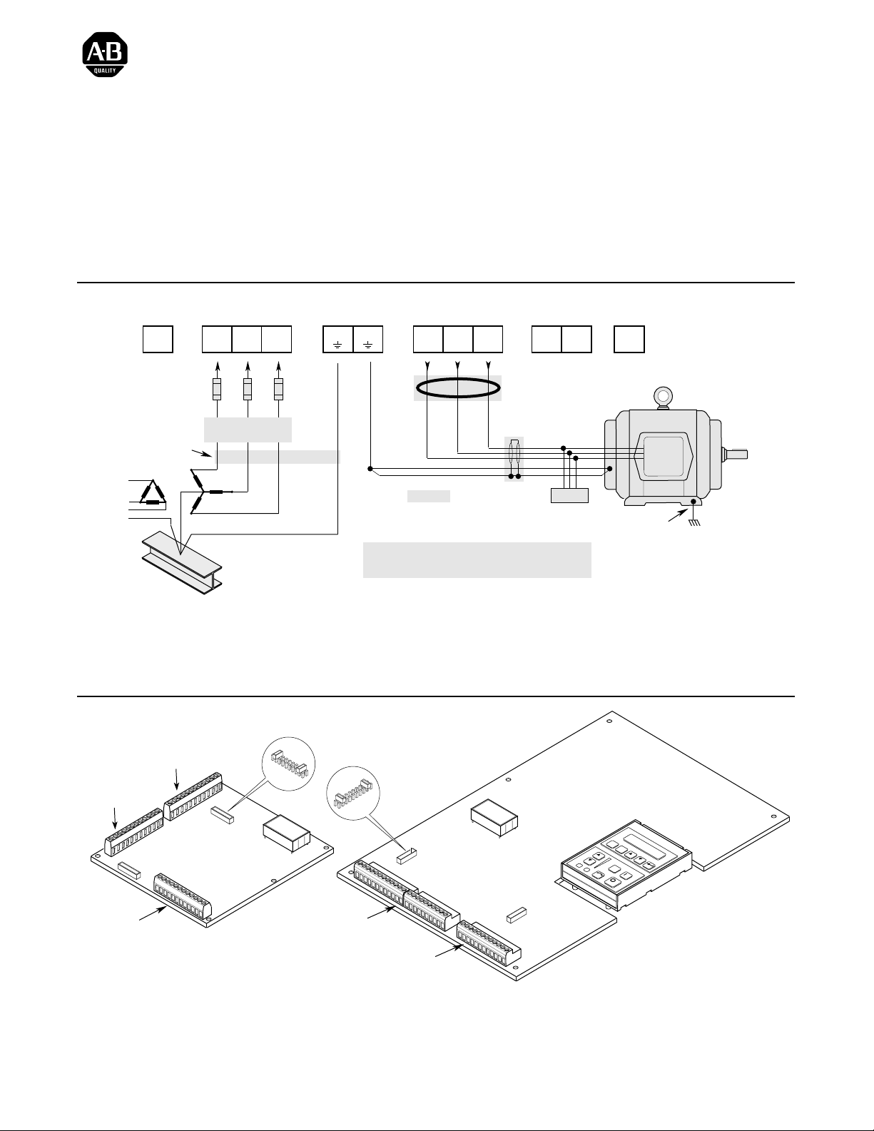
Power Wiring – TB1
TE
Ground
TE
(Not on all drives) (Not on all drives)
Required
Input Fusing
Conduit/4-Wire Cable
Nearest
Building Structure Steel
AC Input
to Drive
R
S
(L1)
(L2)T(L3)
Required Branch
Circuit Disconnect
PE
Ground
PE PE
Important: Verify motor insulation system peak voltage
Diagram shows connections that are common for all drives.
Drive Output
to Motor
U
(T1)V(T2)W(T3)
Common Mode Core*
Shield*
* Optional
rating. For cable lengths greater than 6.1
meters (20 feet), consult the User Manual.
Refer to User Manual for Detailed Information.
Dynamic Brake
DC
+
Motor
Terminator*
Jumper Locations
DC
–
BRK
–
Motor Frame
PE
Ground per
Local Codes
J4 (TB4)
J7 (TB7)
J10 (TB10)
Frames A1 – A4
Publication 1336 IMPACT-5.5EN – May, 1999
J5
LANGUAGE MODULE
ALLEN-BRADLEY
L Option Board
Jumpers
J2
TB10
TB11
LANGUAGE MODULE
ALLEN-BRADLEY
ESC
SEL
JOG
All Other Frames
Page 2
1336 IMPACT Quick Start Guide
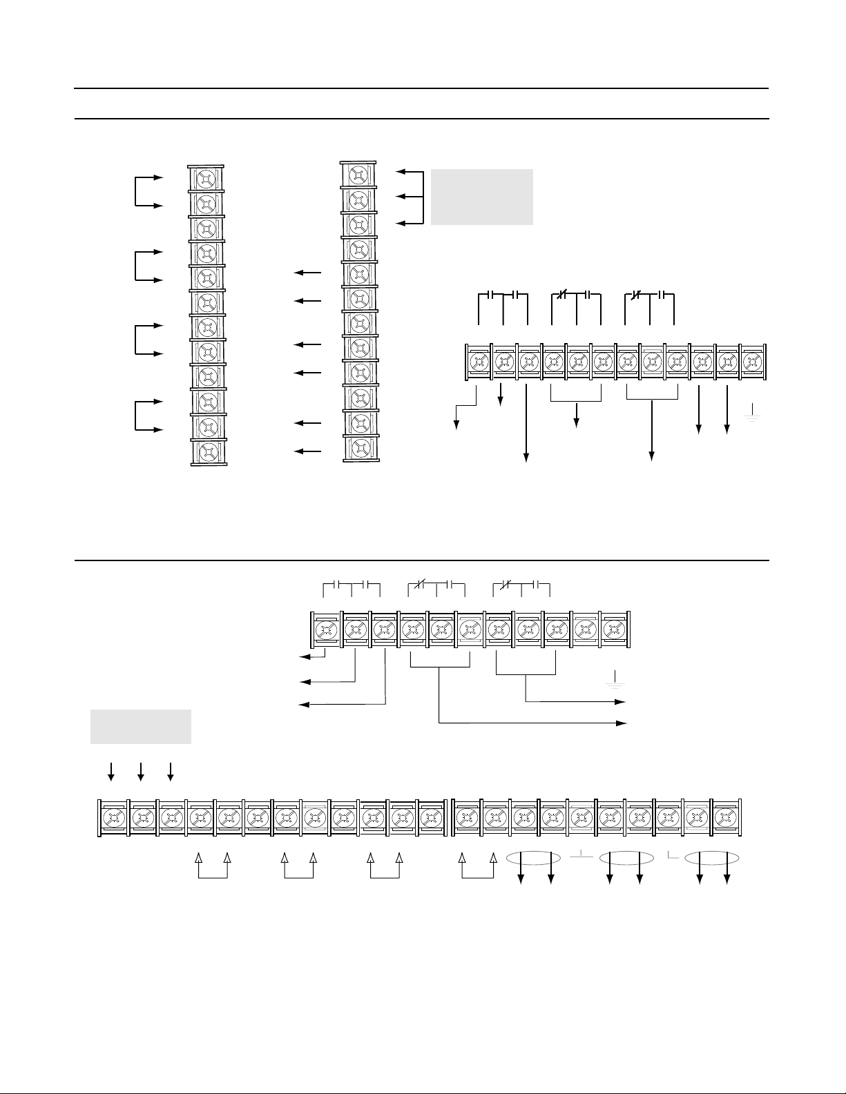
Wiring I/O – A-Frames
Analog
Input 1
Analog
Input 2
4 to 20 mA
Pulse
Source
J7 (TB7)
+
Shield
+
Shield
+
Shield
+
Shield
J4 (TB4)
1
-
-
-
-
2
3
4
5
6
7
8
9
10
11
12
Analog
Output 2
+10V
Com
-10V
Shield
Analog
Output 1
Shield
Shield
4 to 20 mA
+
-
+
-
+
-
1
2
3
4
5
6
7
8
9
10
11
12
DC Power
Supply*
J10 (TB10)
123456789101112
Supply
Relay 1
Default: At Speed
Default: Enable
* The power supply is for drive
input use only.
Relay 3
Default: Not Fault
Relay 2
Default: Not Warning
(Run)
TE
Voltage
Clearance
Relay 4
(Alarm)
Wiring I/O - All Other Frames
TB11
Relay 1
Default:
At Speed
Supply
TB10
DC Power
Supply
+10V Com -10V
1 23456789
+++++++-------
Analog
Input 1
Relay 2
Default:
Enable (Run)
SH SH SH SH SH
Analog
Input 2
123
10 11 12
4-20 mA
Input
4
6
5
789 10
TE
Voltage
Clearance
Relay 4 Default:
Not Warning (Alarm)
Relay 3 Default: Not Fault
13 14 15 16 17 18 19 20 21 22
Pulse
Source
Analog
Output 1
Analog
Output 2
4-20 mA
Output
2Publication 1336 IMPACT-5.5EN – May, 1999
Page 3
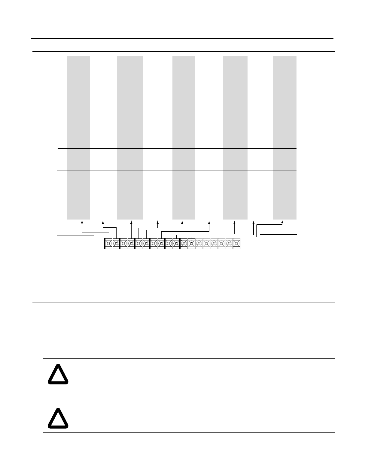
L Option Board
1
Status
2
Start
3
Start
4
Start
5
Start
6
Start
7
Start
8
Start
9
Start
10
Start
11
Start
12
Run Fwd
13
Run Fwd
14
Run Fwd
15
Run Fwd
16
Run Fwd
17
Start
18
Start
19
Start
20
Start
21
Start
22
Start
23
Run Fwd
24
Run Fwd
25
Run Fwd
26
Run Fwd
27
Start
28
Start
29
Start
30
Run Fwd
Spd Select
3
2
1
0
0
0 - Speed Ref 1
0
0
1 - Speed Ref 2
0
1
0 - Speed Ref 3
0
1
1 - Speed Ref 4
1
0
0 - Speed Ref 5
1
0
1 - Speed Ref 6
1
1
0 - Speed Ref 7
1
1
1 - No Change, Last State
Stop/Clr Flt
Stop/Clr Flt
Stop/Clr Flt
Stop/Clr Flt
Stop/Clr Flt
Stop/Clr Flt
Stop/Clr Flt
Stop/Clr Flt
Stop/Clr Flt
Stop/Clr Flt
Stop/Clr Flt
Stop/Clr Flt
Stop/Clr Flt
Stop/Clr Flt
Stop/Clr Flt
Stop/Clr Flt
Stop/Clr Flt
Stop/Clr Flt
Stop/Clr Flt
Stop/Clr Flt
Stop/Clr Flt
Stop/Clr Flt
Stop/Clr Flt
Stop/Clr Flt
Stop/Clr Flt
Stop/Clr Flt
Stop/Clr Flt
Stop/Clr Flt
Stop/Clr Flt
Stop/Clr Flt
19
1336 IMPACT Quick Start Guide
Status
Rev/Fwd
Rev/Fwd
Rev/Fwd
Rev/Fwd
Rev/Fwd
Reverse
Reverse
MOP Incr
Reverse
Accel 1
Run Rev
Run Rev
Run Rev
Run Rev
Run Rev
Rev/Fwd
Rev/Fwd
Spd/Trq 3
Spd/Trq 3
Reverse
Spd/Trq 3
Run Rev
Run Rev
Run Rev
Run Rev
Rev/Fwd
MOP Incr
Reverse
Run Rev
20 21 22 23 24 25 26 27 28 29 30 31 32 33 34 35 36
Common
Status
Jog
Stop Type
Accel 2*/1
MOP Incr
Jog
Forward
Forward
MOP Decr
Forward
Accel 2
Loc/Rem
Stop Type
Accel 2*/1
MOP Incr
Loc/Rem
PTrim En
Flux Enable
Spd/Trq 2
Spd/Trq 2
Forward
Spd/Trq 2
PTrim En
Flux Enable
PTrim En
Jog
MOP Incr
MOP Decr
Forward
MOP Incr
Common
Status
Ext Flt
Ext Flt
Ext Flt
Ext Flt
Ext Flt
Ext Flt
Ext Flt
Ext Flt
Ext Flt
Ext Flt
Ext Flt
Ext Flt
Ext Flt
Ext Flt
Ext Flt
Ext Flt
Ext Flt
Ext Flt
Ext Flt
Ext Flt
Ext Flt
Ext Flt
Ext Flt
Ext Flt
Ext Flt
Ext Flt
Ext Flt
Ext Flt
Ext Flt
Common
Status
Spd Sel 3
Spd Sel 3
Decel 2*/1
MOP Decr
Loc/Rem
Jog
Spd Sel 3
Spd Sel 3
MOP Incr
Decel 1
Spd Sel 3
Spd Sel 3
Decel 2*/1
MOP Decr
Stop Type
Ramp Dis
Reset
Spd/Trq 1
Spd/Trq 1
Ramp Dis
Spd/Trq 1
Reset
Reset
Ramp Dis
Spd Sel 3
MOP Decr
Spd Sel 3
MOP Incr
MOP Decr
Encoder B
Encoder NOT A
Status
Spd Sel 2
Spd Sel 2
Spd Sel 2
Spd Sel 2
Spd Sel 2
Spd Sel 2
Spd Sel 2
Spd Sel 2
MOP Decr
Decel 2
Spd Sel 2
Spd Sel 2
Spd Sel 2
Spd Sel 2
Spd Sel 2
Spd Sel 2
Spd Sel 2
PTrim En
Flux Enable
Reset
Spd Sel 2
Spd Sel 2
Spd Sel 2
Spd Sel 2
Spd Sel 2
Spd Sel 2
Spd Sel 2
MOP Decr
Spd Sel 2
Encoder A
(200mA max.)
Encoder NOT B
+12V
Status
Spd Sel 1
Spd Sel 1
Spd Sel 1
Spd Sel 1
Spd Sel 1
Spd Sel 1
Spd Sel 1
Spd Sel 1
Spd Sel 1
Spd Sel 1
Spd Sel 1
Spd Sel 1
Spd Sel 1
Spd Sel 1
Spd Sel 1
Spd Sel 1
Spd Sel 1
Spd Sel 1
Spd Sel 1
Spd Sel 1
Spd Sel 1
Spd Sel 1
Spd Sel 1
Spd Sel 1
Spd Sel 1
Spd Sel 1
Spd Sel 1
Spd Sel 1
Spd Sel 1
3
0
0
0
0
1
1
1
1
Encoder Common
Enable
Enable
Enable
Enable
Enable
Enable
Enable
Enable
Enable
Enable
Enable
Enable
Enable
Enable
Enable
Enable
Enable
Enable
Enable
Enable
Enable
Enable
Enable
Enable
Enable
Enable
Enable
Enable
Enable
Enable
Spd/Trq Select
2
1
0
0 - Zero Torque
0
1 - Speed Reg
1
0 - Torque Reg
1
1 - Min Trq/Spd
0
0 - Max Trq/Spd
0
1 - Sum Trq/Spd
1
0 - Zero Torque
1
1 - Zero Torque
Start-Up
This start-up procedure co vers only the most commonly adjusted values using the 1 336 IMPACT “Startup” mode. Refer to the
User Manual for detailed information.
The following procedure is written for users who have a Human Interface Module (HIM) installed. For users without a HIM,
respective external commands and signals must be supplied. It is also assumed that all parameters are at factory default
settings.
ATTENTION: Power must be applied to the drive to perform the following. Some of the voltages present
are at incoming line potential. T o avoid a shock hazard or damage to equipment, only qualified driv e service
!
!
Publication 1336 IMPACT-5.5EN – May, 19993
personnel should perfo rm the fo l lowing procedure. Thoroughly read and under sta n d th e pro cedure before
beginning. If an e ven t does not occur while perfor ming this procedure, Do Not Proceed. Remo ve po wer b y
opening the branch circuit disconnect device and correct the malfunction before continuing.
ATTENTION: To avoid a hazard of electric shock when wiring or servicing the drive, verify that the
voltage on the bus capacitors has discharged. Measure the DC bus v oltage at the + and - terminals of TB1.
The voltage must be zero.
Page 4
1336 IMPACT Quick Start Guide
1. Verify that AC line power and control power match the drive rating.
2. If an L option is installed, verify that the Stop and Enable interlock inputs are present. If this option is not installed, verify
that jumpers are installed at pins 3 and 4 and 17 and 18 on J5 on A Frame drives or J2 on B Frame and up drives. Ref er to
Jumper Locations.
3. If standard I/O is being used, verify that jumpers are wired correctly.
4. If Analog Option is installed, verify that parameters are properly configured (refer to the User Manual).
ATTENTION: In all of the following steps, rotation of the motor may occur. To guard against injury ,
incorrect rotation, and possible equipment damage, read each step carefully and perform with caution.
!
5. Apply AC power and control voltages to the drive. The LCD display should light and display a drive status of “Stopped”
and an output frequency of “+0.00 Hz.” If the drive detects a fault, a statement relating to the fault will be shown on the
display. Record the information, remove power, and correct the fault source before proceeding.
6. From the Status Display, press the Enter key (or any key). “Choose Mode” will be displayed . Pres s the Increment (or
Decrement) key until “Startup is displayed. Press Enter.
Important: All questions can be answered Yes or No. Pressing Enter will select the default (“Y” or “N”). Pressing the
Increment (or Decrement) key will change the selection. Press Enter to select. Choosing “Y” allows you to proceed
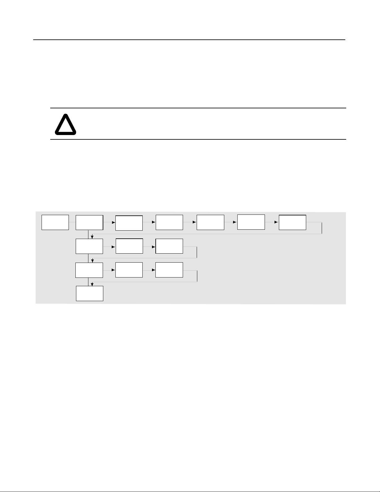
through the step, and choosing “No” will advance you to th e next step . The figure below shows the steps involved.
Startup
Quick Motor
Tune?
No
Configure
Digital?
No
Configure
Analog?
No
Done
Yes
Enter Motor
Data?
Relay
Yes Yes
Output
Inputs
Yes Yes
Yes Yes Yes Yes
Encoder?
L Option
Outputs
Regen/
Brake?
Phase
Rotation?
Autotune?
Important: Pleas e note the following:
• The “Startup” mode can be e xit ed at an y time by pressing ESCape until the Status Display i s shown. If you wish
to re-enter the “Startup” mode, simply select “Reset Sequence” to start from the beginning. Selecting “Continue”
allows you to resume from the point where you left off.
• Completing the last action in any step will automatically take you to th e next step.
• Pressing SELect will activate line 2 of the display. This must be done for all values.
• Press the Increment (or Decrement) key to adjust a value (skip if value is correct). Press Enter to store the value
or retain existing value. Pressing Enter again will cause you to move to the next step (parameter)
7. Cycle power to acti v ate changes. This completes the “Assisted Startup” procedure. Depending o n your application, furt her
parameter programming and/or “Advanced Startup” may be required. Refer to the User Manual for details.
4Publication 1336 IMPACT-5.5EN – May, 1999
Page 5

1336 IMPACT Quick Start Guide
Drive Dimensions
To determine the size of your drive, refer to the following illustration and table.
Depth
HIM Operation
Width
Height
Frame
A1
A2
A3
A4
B
C
D
E-Enclosed
E-Open
F
G
H
➀
Fan height (635.0 (25.00)) not included.
Width x Height x Depth
Millimeters (inches)
215.9 (8.50) x 290.0 (11.42) x 160.0 (6.30)
215.9 (8.50) x 290.0 (11.42) x 180.5 (7.10)
215.9 (8.50) x 290.0 (11.42) x 207.0 (8.15)
260.0 (10.24) x 350.0 (13.78) x 212.0 (8.35)
276.4 (10.88) x 476.3 (18.75) x 225.0 (8.86)
301.8 (11.88) x 701.0 (27.60) x 225.0 (8.86)
381.5 (15.02) x 1240.0 (48.82) x 270.8 (10.66)
511.0 (20.12) x 1498.6 (59.00) x 477.5 (18.80)
511.0 (20.12) x 1498.6 (59.00) x 372.6 (14.67)
762.0 (30.00) x 2286.0 (90.00) x 635.0 (25.00)
762.0 (30.00) x 2387.6 (94.0) x 635.0 (25.00)
1270.0 (50) x 2324.1 (91.50)➀ x 635.0 (25)
Parameter programming or viewing is accomplished through the Program or Display modes shown below.
1. From the Status Display, press to display “Choose Mode.”
2. Press or to display “Program” (or “Display”).
3. Press .
4. Press or until the desired file is displayed.
5. Press .
6. Press or until the desired group is displayed.
7. Press .
8. Press or to scroll to the desired pa rameter.
Publication 1336 IMPACT-5.5EN – May, 19995
Page 6

HIM Structure
1336 IMPACT Quick Start Guide
Power-Up and
Status Display
or or or or
Choose Mode
EEProm Search Password Display Process
Save Values
Recall Values
Reset Defaults
Drive to HIM
HIM to Drive
Parameters
Links
Control
Status
Control Logic
Reset Drive1
Fault Queue
Warning Queue
Login
Logout
Modify
Process Display
Program
Operator Level
Mode Level
Link Start Up
Set Links
Clear All Links
Monitor
Motor Status
Drive/Inv Status
SCANport Status
Fault Status
Testpoints
Control
Drive Logic Select
Control Limits
Speed/Torq Mode
Speed Reference
Accel/Decel
Torque Reference
Feedback Device
Speed Feedback
Speed Regulator
Fault Setup
Fault Config
Fault Limits
Test Points
Interface/
Comm
Digital Config
Analog Inputs
Analog Outputs
SCANport Config
SCANport Status
SCANport Analog
Gateway Data In
Gateway Data Out
Parameters
(See Next Page)
Motor/
Inverter
Motor Nameplate
Encoder Data
Inverter
Motor Constants
File Level
Application Autotune
Group Level
Flux Braking
DC Braking/Hold
Max Mtr Current
Fast Flux Up
Start Dwell
Prog Function
Bus Reg/Control
Process Trim
Flying Start
Autotune Setup
Autotune Status
Autotune Results
Drive to HIM
HIM to Drive
Element Level
Publication 1336 IMPACT-5.5EN – May, 19996
Page 7

1336 IMPACT Quick Start Guide
Parameters - Files, Groups, and Elements
Name No. Min./Max. Value Name No. Min./Max. Value
Monitor Neg Mtr Cur Lim 73 Calc/0.0%
Motor Status Pos Torque Lim 74 0.0%/Calc
Motor Speed 81 -8 x BMS/+8 x BMS Neg Power Lim 75 Calc/0.0%
Motor Frequency 89 -250.000/+250.000 Hz Regen Power Lim 76 -800.0%/0.0%
Motor Current 83 0.0/6553.5 amps Current Rate Lim 77 Calc/200.0%
Motor Voltage 85 0/+3000 volts Max Mtr Current 195 0/1
Motor Voltage % 234 0/800% Min Speed Limit 215 0.0
Motor Torque % 86 -800.0/+800.0%
Speed/Torq Mode
Motor Flux % 88 12.5/100.0% Spd/Trq Mode Sel 68 0/5
Motor Power% 90 -800.0/+800.0%
Speed Reference
Enc Pos Fdbk Low 227 0/65535 Speed Ref 1 29 -8x/+8xBMS rpm
Enc Pos Fdbk Hi 228 0/65535 Speed Scale 1 30 -3.9999/+3.9999
Int Torque Ref 229 -800/+800% Speed Ref 2 31 -8x/+8xBMS rpm
Drive/Inv Status Speed Ref 3 32 -8x/+8xBMS rpm
DC Bus Voltage 84 0/1000V Speed Ref 4 33 -8x/+8xBMS rpm
Logic Input Sts 14 Bit selection Speed Ref 5 34 -8x/+8xBMS rpm
Drive/Inv Status 15 Bit selection Speed Ref 6 35 -8x/+8xBMS rpm
Drive/Inv Sts 2 196 Bit selection Speed Ref 7 36 -8x/+8xBMS rpm
Run Inhibit Sts 16 Bit selection Speed Scale 7 37 -3.9999/+3.9999
Command Spd Sts 82 -8 x BMS/+8 x BMS Jog Speed 1 38 -8x/+8xBMS rpm
Torque Limit Sts 87 Bit selection Jog Speed 2 39 -8x/+8xBMS rpm
Spd Reg Output 225 -300.0/+300.0%
Accel/Decel
Spd Error 226 -8 x BMS/+8 x BMS Accel Time 1 42 0.0/6553.5 sec
SCANport Status Accel Time 2 43 0.0/6553.5 sec
Dir/Ref Owner 128 Bit selection Decel Time 1 44 0.0/6553.5 sec
Start/Stop Owner 129 Bit selection Decel Time 2 45 0.0/6553.5 sec
Jog1/Jog2 Owner 130 Bit selection S-Curve Percent 47 0.0/100.0%
Ramp/ClFlt Owner 131 Bit selection
Torque Reference
Flux/Trim Owner 132 Bit selection Torque Ref 1 69 -800.0/+800.0%
Fault Status Slave Torque % 70 -200.00/+200.00%
PwrUp Flt Status 219 Bit selection
Feedback Device
Ncfg Flt Status 220 Bit selection Fdbk Device Type 64 1/3
Fault Status 1 221 Bit selection Encoder PPR 8 Calc/20000 ppr
Fault Status 2 222 Bit selection
Speed Feedback
Warning Status 1 223 Bit selection Scaled Spd Fdbk 63 -32767/+32767
Warning Status 2 224 Bit selection Fdbk Filter Sel 65 0/4
Testpoints Fdbk Filter Gain 66 -5.00/+5.00
Test Data 1 92 -32768/+32767 Fdbk Filter BW 67 0.2/900.0 rad/sec
Test Select 1 93 0/65535 Notch Filtr Freq 185 5.0/135.0 Hz
Test Data 2 94 -32768/+32767 Notch Filtr Q 186 2/500
Test Select 2 95 0/65535
Speed Regulator
Control Total Inertia 157 0.01 sec/655.00 sec
Drive Logic Select Spd Desired BW 161 0.00 rad/sec/Calc
Logic Options 17 Bit selections Ki Speed Loop 158 0.0/4095.9
Stop Dwell Time 18 0.0/10.0 sec Kp Speed Loop 159 0.0/200.0
Zero Speed Tol 19 0.0 rpm/8xBMS rpm Kf Speed Loop 160 0.500/1.000
Start Dwell Spd 193 -0.1/+0.1 x BMS Error Filtr BW 162 Calc/1500.0 rad/sec
Start Dwell Time 194 0.0/10.0 sec Droop Percent 146 0.0/25.5%
Control Limits Fault Setup
Rev Speed Limit 40 -6xBMS rpm/0.0 rpm
Fault Config
Fwd Speed Limit 41 0.0 rpm/+6xBMS rpm Fault Select 1 20 Bit selection
Pos Mtr Cur Lim 72 0.0%/Calc Warning Select 1 21 Bit selection
/BMS rpm
7Publication 1336 IMPACT-5.5EN – May, 1999
Page 8

1336 IMPACT Quick Start Guide
Name No. Min./Max. Value Name No. Min./Max. Value
Fault Config cont. SCANport Config
Fault Select 2 22 Bit Selection SP2 Wire Enable 181 Bit Selection
Warning Select 2 23 Bit Selection SP Enable Mask 124 Bit Selection
Fault Limits Dir/Ref Mask 125 Bit Selection
Absolute Overspd 24 0.0 rpm/BMS rpm Start/Jog Mask 126 Bit Selection
Motor Stall Time 25 0.1/3276.7 sec Clr Flt/Res Mask 127 Bit Selection
Motor Overload % 26 110.0/400.0%
SCANport Status
Line Undervolts 27 10.0/90.0% Dir/Ref Owner 128 Bit selection
Testpoints Start/Stop Owner 129 Bit selection
Test Data 1 92 -32768/+32768 Jog1/Jog2 130 Bit selection
Test Select 1 93 0/65535 Ramp/CIFlt Owner 131 Bit selection
Test Data 2 94 -32768/+32767 Flux/Trim Owner 132 Bit selection
Test Select 2 95 0/65535
SCANport Analog
Interface/Comm SP An In1 Select 133 1/16
Digital Config SP An In1 Value 134 -32767/+32767
Relay Config 114 0/38 SP An In1 Scale 135 -1.000/+1.000
Relay Config 1 115 -800.0/+800.0% Sp An In2 Select 136 1/16
Relay Config 2 187 0/36 Sp An In2 Value 137 -32767/+32767
Relay Setpoint 2 188 800.0/+800.0 Sp An In2 Scale 138 -1.000/+1.000
Relay Config 3 189 0/36 Sp An Output 139 -32767/+32767
Relay Setpoint 3 190 -800.0/+800.0
Gateway Data In
Relay Config 4 191 0/36 Data In A1 140 -32767/+32767
Relay Setpoint 4 192 -800/+800.0% Data In A2 141 -32767/+32767
L Option Mode 116 1/25 Data In B1 142 -32767/+32767
L Option In Sts 117 Bit Selection Data In B2 143 -32767/+32767
Mop Increment 118 0.0/BMS Data In C1 144 -32767/+32767
Mop Value 119 0.0/BSMNA Data In C2 145 -32767/+3276
Pulse In PPR 120 500/2000 Data In D1 146 -32767/+32767
Pulse In Scale 121 0.01/10.00 Data In D2 147 -32767/+32767
Pulse In Offset 122 -BMS/+BMS
Gateway Data Out
Pulse In Value 123 0.0/+8xBMS Data Out A1 148 -32767/+32767
Analog Inputs Data Out A2 149 -32767/+32767
An In 1 Value 96 -32767/+32767 Data Out B1 150 -32767/+32767
An In 1 Offset 97 -19.980/+19.980 volts Data Out B2 151 -32767/+32767
An In 1 Scale 98 -16.000/+16.000 Data Out C1 152 -32767/+32767
An In 1 Filter BW 182 0.0/200.0 rad/sec Data Out C2 153 -32767/+32767
An In 2 Value 99 -32767/+32767 Data Out D1 154 -32767/+32767
An In 2 Offset 100 -19.980/+19.980 volts Data Out D2 155 -32767/+32767
An In 2 Scale 101 -16.000/+16.000
An In2 Filter BW 183 0.0/200.0 rad/sec
mA Input Value 102 -32767/+32767
mA In Offset 103 -32.000/+32.000 mA
mA In Scale 104 -16.00
mA In Filter BW 184 0.0/200.0 rad/sec
Analog Outputs
An Out 1 Value +0 105 -32767/+32767
An Out 1 Offset 106 -20.000/+20.000
An Out 1 Scale 107 -1.000/+1.000
An Out 2 Value 108 -32767/+32767
An Out 2 Offset 109 -19.980/+19.980 volts
An Out 2 Scale 110 -1.000/+1.000
mA Out Value 111 -32767/+32767
mA Out Offset 112 -32.000/+32.000 mA
mA Out Scale 113 -1.000/+1.000
8Publication 1336 IMPACT-5.5EN – May, 1999
Page 9

1336 IMPACT Quick Start Guide
Name No. Min./Max. Value Name No. Min./Max. Value
Motor Inverter Function Sel 212 0/27
Motor Nameplate Function Output1 213 Varies
Nameplate HP 2 0.2 hp/2000.0 hp Function Output2 214 0/65535
Nameplate RPM 3 1 rpm/1500 rpm Function In9 232 -32767/+32767
Nameplate Amps 4 0.1 amps/Calc Function In 10 233 -32767/+32767
Nameplate Volts 5 75 volts/575 volts
Bus Reg Control
Namplate Hz 6 1.0/250.0 Hz Bus/Brake Option 13 Bit selection
Motor Poles 7 2/40 poles
Process Trim
Service Factor 9 1.00/2.00 PTrim Output 48 -800.0/+800.0%
Encoder Data PTrim Reference 49 -800.0/+800.0%
Encoder PPR 8 Calc/2000 ppr PTrim Feedback 50 -800.0/+800.0%
Inverter PTrim Select 51 Bit selection
PWM Frequency 10 1000 Hz/From drive PTrim Filter BW 52 0.0/240.0 rad/sec
Inverter Amps 11 0.1 amps/From drive PTrim Preload 53 -800.0/+800.0%
Inverter Volts 12 75/575 volts PTrim Ki 54 0.000/16.000
Motor Constants PTrim Kp 55 0.000/16.000
Stator Resistance 166 0.00/100.00% PTrim Lo Limit 58 -800.0/+800.0%
Leak Inductance 167 0.00/100.00% PTrim Hi Limit 59 -800.0/+800.0%
Flux Current 168 0.00/75.00% PTrim Out Gain 60 -8.000/+8.000
Slip Gain 169 0.0/400.0% Max Rev Spd Trim 61 -6 x /0.0 BMS rpm
Motor Poles 7 2/40 poles Max Fwd Spd Trim 62 0.0 rpm/+6xBMS rpm
Application Flying Start
Flux Braking FStart Select 216 0/2
Bus/Brake Option 13 Bit selection FStart Speed 217 P40/P41
DC Braking/Hold Autotune
Bus/Brake Option 13 Bit selection Autotune Setup
DC Brake Current 79 0.0%/Calc Autotune/Dgn Sel 173 Bit selection
DC Brake Time 80 0.0/6553.5 sec Trans Dgn Config 172 Bit selection
400% Mtr Current Autotune Torque 64 250%/100.0%
Max Mtr Current 195 0/1 Autotune Speed 165 0.3 x BMS/BMS
Fast Flux Up Autotune Status
Bus/Brake Option 13 Bit selection Autotune Status 156 Bit selection
Fast Flux Level 78 100.0%/Calc Inverter Dgn 1 174 Bit selection
Start Dwell Inverter Dgn 2 175 Bit selection
Start Dwell Spd 193 -0.1 x / +0.1 x BMS Autotune Errors 176 Bit selection
Start Dwell Time 194 0.0/10.0 sec
Autotune Results
Prog Function Stator Resistance 166 0.00/100.00%
Function In1 198 Varies Leak Inductance 167 0.00/100.00%
Func 1 Mask/Val 199 Varies Flux Current 168 0.00/75.00%
Func 1 Eval Sel 200 0/17 Slip Gain 169 0.0/400%
Function In2 201 Varies Total Inertia 157 0.0/655.00 sec
Func 2 Mask/Val 202 Varies Spd Desired BW 161 0.00/Calc rad/sec
Func 2 Eval Sel 203 0/17
Function In3 204 Varies
Func 3 Mask/Val 205 Varies
Func 3 Eval Sel 206 0/17
Function In4 207 Varies
Function In5 208 Varies
Function In6 209 Varies
Function In7 210 Varies
Function In8 211 Bit selection
Publication 1336 IMPACT-5.5EN – May, 19999
Page 10

1336 IMPACT Quick Start Guide
This Page Intentionally Blank
10Publication 1336 IMPACT-5.5EN – May, 1999
Page 11

1336 IMPACT Quick Start Guide
Publication 1336 IMPACT-5.5EN – May, 199911
Page 12

Allen-Bradley, a Rockwell Automation Business, has been helping its customers improve
productivity and quality for more than 90 years. We design, manufacture and support a broad range
of automation products worldwide. They include logic processors, power and motion control devices,
operator interfaces, sensors and a variety of software. Rockwell is one of the world’s leading
technology companies.
Worldwide representation.
Argentina • Australia • Austria • Bahr ain • Belgium • Brazil • Bulgaria • Canada • Chile • China, PRC • Colombia • Costa Rica • Croatia • Cyprus • Czech Republic • Denmark •
Ecuador • Egypt • El Salvador • Finland • France • Germany • Greece • Guatemala • Honduras • Hong Kong • Hungary • Iceland • India • Indonesi a • Ireland • Israel • Italy •
Jamaica • Japan • Jordan • Korea • Kuwait • Lebanon • Malaysia • Mexico • Netherlands • New Zealand • Norway • Pakistan • Peru • Philippines • Poland • Portugal • Puerto Rico •
Qatar • Romania • Russia-CIS • Saudi Arabia • Singapore • Slovakia • Slovenia • South Africa, Republic • Spain • Sweden • Switzerland • Taiwan • Thailand • Turkey • United Arab
Emirates • United Kingdom • United States • Uruguay • Venezuela • Yugoslavia
Allen-Bradley Headquarters, 1201 South Second Street, Milwaukee, WI 53204 USA, Tel: (1) 414 382-2000 Fax: (1) 414 382-4444
Publication 1336 IMPACT-5.5EN – May, 1999
Copyright 1997 Rockwell Automat ion. Printed in USA
 Loading...