

Page 1
1336 IMPACT Quick Start Guide
This Quick Start Guide summarizes the basic steps needed to install, start-up, and program the 1336 IMPACT Adjustable
Frequency AC Drive. The information provided Does Not replace the User Manual and is intended for qualified drive service
personnel only. Refer to the 1336 IMPACT User Manual (publication 1336 IMPACT-5.0) for details on other application
considerations and related precautions.
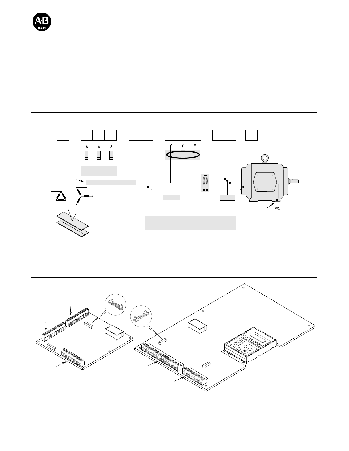
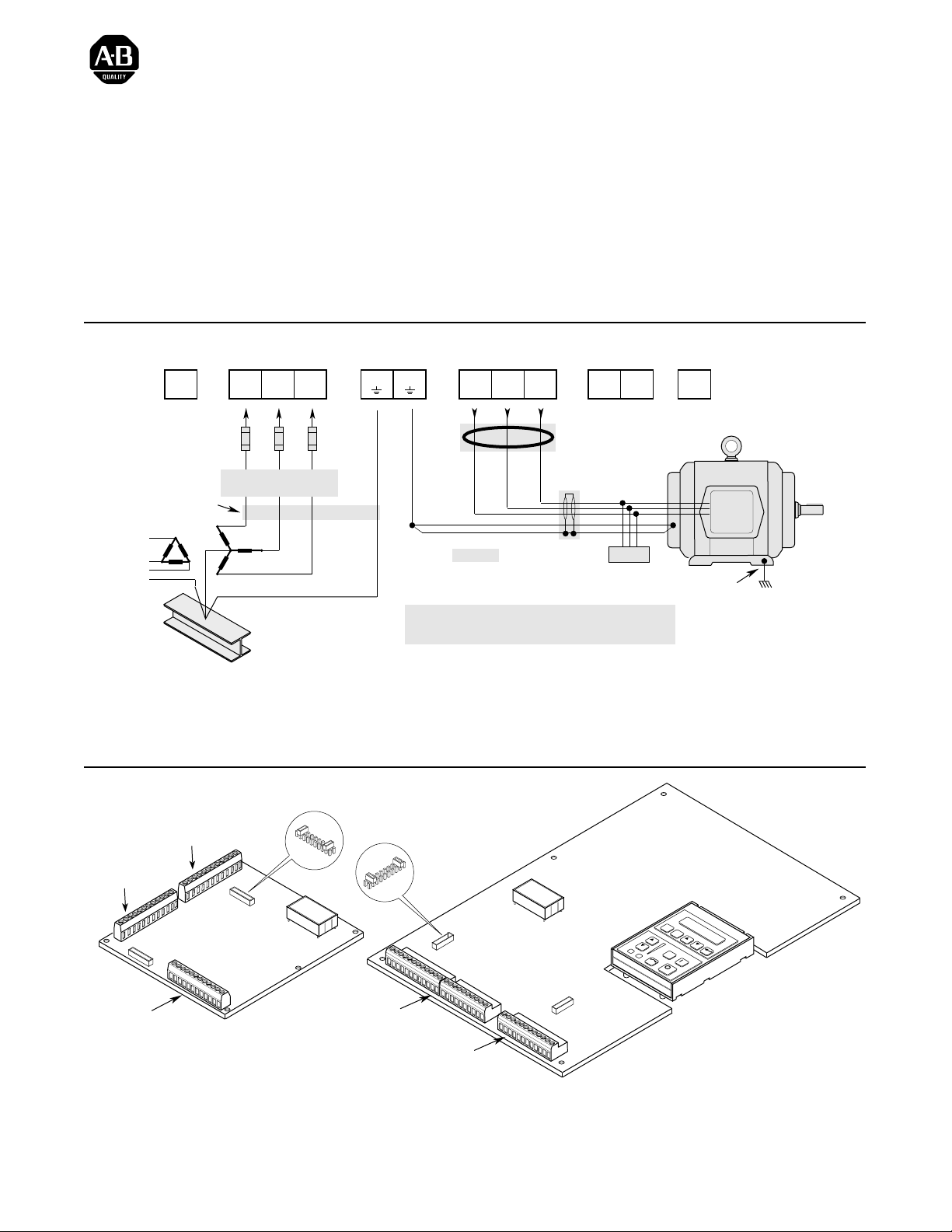
Power Wiring – TB1
TE
Ground
TE
(Not on all drives) (Not on all drives)
Required
Input Fusing
Conduit/4-Wire Cable
Nearest
Building Structure Steel
AC Input
to Drive
R
S
(L1)
(L2)T(L3)
Required Branch
Circuit Disconnect
PE
Ground
PE PE
Important: Verify motor insulation system peak voltage
Diagram shows connections that are common for all drives.
Drive Output
to Motor
U
(T1)V(T2)W(T3)
Common Mode Core*
Shield*
* Optional
rating. For cable lengths greater than 6.1
meters (20 feet), consult the User Manual.
Refer to User Manual for Detailed Information.
Dynamic Brake
DC
+
Motor
Terminator*
Jumper Locations
DC
–
BRK
–
Motor Frame
PE
Ground per
Local Codes
J4 (TB4)
J7 (TB7)
J10 (TB10)
Frames A1 – A4
Publication 1336 IMPACT-5.5ML – May, 1999
J5
LANGUAGE MODULE
ALLEN-BRADLEY
L Option Board
Jumpers
J2
TB10
TB11
LANGUAGE MODULE
ALLEN-BRADLEY
ESC
SEL
JOG
All Other Frames
Page 2
1336 IMPACT Quick Start Guide
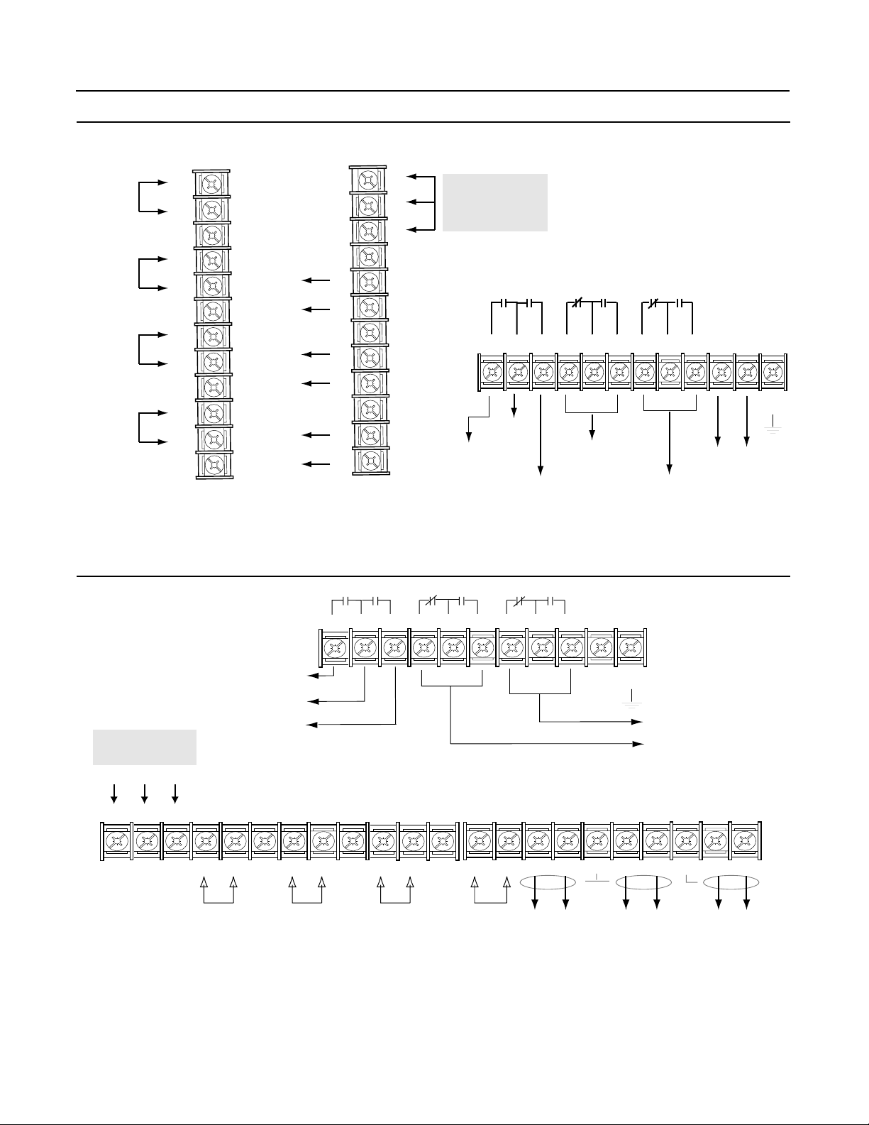
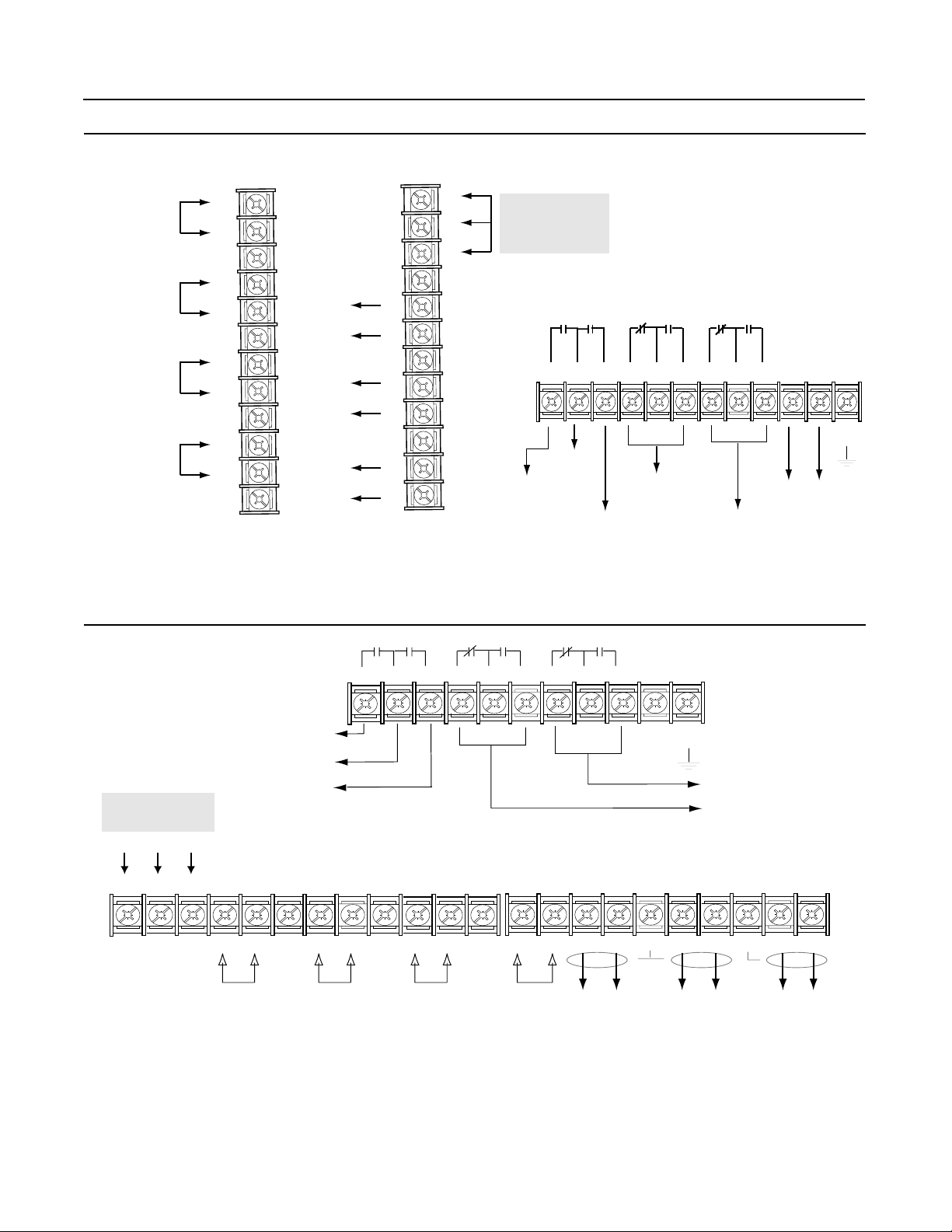
Wiring I/O – A-Frames
Analog
Input 1
Analog
Input 2
4 to 20 mA
Pulse
Source
J7 (TB7)
+
Shield
+
Shield
+
Shield
+
Shield
J4 (TB4)
1
-
-
-
-
2
3
4
5
6
7
8
9
10
11
12
Analog
Output 2
+10V
Com
-10V
Shield
Analog
Output 1
Shield
Shield
4 to 20 mA
+
-
+
-
+
-
1
2
3
4
5
6
7
8
9
10
11
12
DC Power
Supply*
J10 (TB10)
123456789101112
Supply
Relay 1
Default: At Speed
Default: Enable
* The power supply is for drive
input use only.
Relay 3
Default: Not Fault
Relay 2
Default: Not Warning
(Run)
TE
Voltage
Clearance
Relay 4
(Alarm)
Wiring I/O - All Other Frames
TB11
Relay 1
Default:
At Speed
Supply
TB10
DC Power
Supply
+10V Com -10V
1 2345 6789
+++++++-------
Analog
Input 1
Relay 2
Default:
Enable (Run)
SH SH SH SH SH
Analog
Input 2
123
10 11 12
4-20 mA
Input
4
6
5
789 10
TE
Voltage
Clearance
Relay 4 Default:
Not Warning (Alarm)
Relay 3 Default: Not Fault
13 14 15 16 17 18 19 20 21 22
Pulse
Source
Analog
Output 1
Analog
Output 2
4-20 mA
Output
2 Publication 1336 IMPACT-5.5ML – May, 1999
Page 3
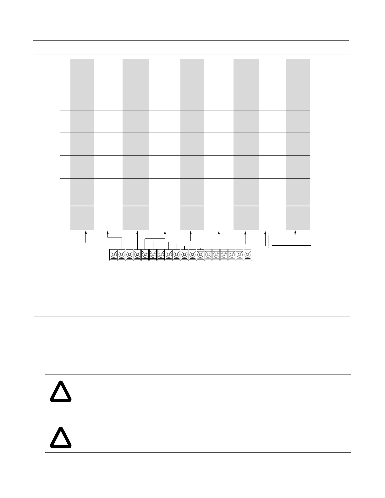
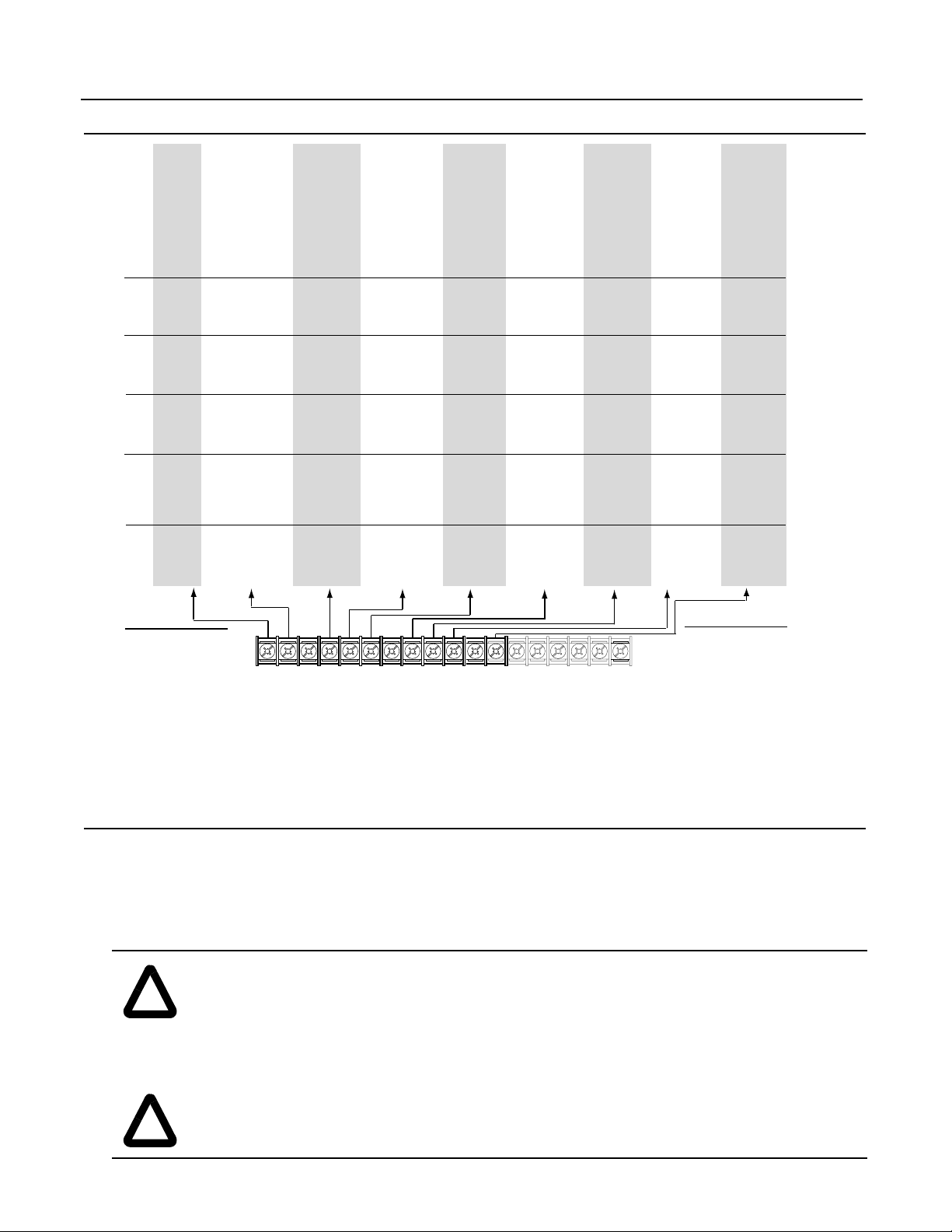
L Option Board
1
Status
2
Start
3
Start
4
Start
5
Start
6
Start
7
Start
8
Start
9
Start
10
Start
11
Start
12
Run Fwd
13
Run Fwd
14
Run Fwd
15
Run Fwd
16
Run Fwd
17
Start
18
Start
19
Start
20
Start
21
Start
22
Start
23
Run Fwd
24
Run Fwd
25
Run Fwd
26
Run Fwd
27
Start
28
Start
29
Start
30
Run Fwd
Spd Select
3
2
1
0
0
0 - Speed Ref 1
0
0
1 - Speed Ref 2
0
1
0 - Speed Ref 3
0
1
1 - Speed Ref 4
1
0
0 - Speed Ref 5
1
0
1 - Speed Ref 6
1
1
0 - Speed Ref 7
1
1
1 - No Change, Last State
1336 IMPACT Quick Start Guide
Stop/Clr Flt
Stop/Clr Flt
Stop/Clr Flt
Stop/Clr Flt
Stop/Clr Flt
Stop/Clr Flt
Stop/Clr Flt
Stop/Clr Flt
Stop/Clr Flt
Stop/Clr Flt
Stop/Clr Flt
Stop/Clr Flt
Stop/Clr Flt
Stop/Clr Flt
Stop/Clr Flt
Stop/Clr Flt
Stop/Clr Flt
Stop/Clr Flt
Stop/Clr Flt
Stop/Clr Flt
Stop/Clr Flt
Stop/Clr Flt
Stop/Clr Flt
Stop/Clr Flt
Stop/Clr Flt
Stop/Clr Flt
Stop/Clr Flt
Stop/Clr Flt
Stop/Clr Flt
Stop/Clr Flt
Status
Rev/Fwd
Rev/Fwd
Rev/Fwd
Rev/Fwd
Rev/Fwd
Reverse
Reverse
MOP Incr
Reverse
Accel 1
Run Rev
Run Rev
Run Rev
Run Rev
Run Rev
Rev/Fwd
Rev/Fwd
Spd/Trq 3
Spd/Trq 3
Reverse
Spd/Trq 3
Run Rev
Run Rev
Run Rev
Run Rev
Rev/Fwd
MOP Incr
Reverse
Run Rev
19 20 21 22 23 24 25 26 27 28 29 30 31 32 33 34 35 36
Common
Status
Jog
Stop Type
Accel 2*/1
MOP Incr
Jog
Forward
Forward
MOP Decr
Forward
Accel 2
Loc/Rem
Stop Type
Accel 2*/1
MOP Incr
Loc/Rem
PTrim En
Flux Enable
Spd/Trq 2
Spd/Trq 2
Forward
Spd/Trq 2
PTrim En
Flux Enable
PTrim En
Jog
MOP Incr
MOP Decr
Forward
MOP Incr
Common
Status
Ext Flt
Ext Flt
Ext Flt
Ext Flt
Ext Flt
Ext Flt
Ext Flt
Ext Flt
Ext Flt
Ext Flt
Ext Flt
Ext Flt
Ext Flt
Ext Flt
Ext Flt
Ext Flt
Ext Flt
Ext Flt
Ext Flt
Ext Flt
Ext Flt
Ext Flt
Ext Flt
Ext Flt
Ext Flt
Ext Flt
Ext Flt
Ext Flt
Ext Flt
Common
Status
Spd Sel 3
Spd Sel 3
Decel 2*/1
MOP Decr
Loc/Rem
Jog
Spd Sel 3
Spd Sel 3
MOP Incr
Decel 1
Spd Sel 3
Spd Sel 3
Decel 2*/1
MOP Decr
Stop Type
Ramp Dis
Reset
Spd/Trq 1
Spd/Trq 1
Ramp Dis
Spd/Trq 1
Reset
Reset
Ramp Dis
Spd Sel 3
MOP Decr
Spd Sel 3
MOP Incr
MOP Decr
Encoder B
Status
Spd Sel 2
Spd Sel 2
Spd Sel 2
Spd Sel 2
Spd Sel 2
Spd Sel 2
Spd Sel 2
Spd Sel 2
MOP Decr
Decel 2
Spd Sel 2
Spd Sel 2
Spd Sel 2
Spd Sel 2
Spd Sel 2
Spd Sel 2
Spd Sel 2
PTrim En
Flux Enable
Reset
Spd Sel 2
Spd Sel 2
Spd Sel 2
Spd Sel 2
Spd Sel 2
Spd Sel 2
Spd Sel 2
MOP Decr
Spd Sel 2
Encoder A
Encoder NOT A
Encoder NOT B
(200mA max.)
+12V
Encoder Common
Status
Spd Sel 1
Spd Sel 1
Spd Sel 1
Spd Sel 1
Spd Sel 1
Spd Sel 1
Spd Sel 1
Spd Sel 1
Spd Sel 1
Spd Sel 1
Spd Sel 1
Spd Sel 1
Spd Sel 1
Spd Sel 1
Spd Sel 1
Spd Sel 1
Spd Sel 1
Spd Sel 1
Spd Sel 1
Spd Sel 1
Spd Sel 1
Spd Sel 1
Spd Sel 1
Spd Sel 1
Spd Sel 1
Spd Sel 1
Spd Sel 1
Spd Sel 1
Spd Sel 1
3
0
0
0
0
1
1
1
1
Enable
Enable
Enable
Enable
Enable
Enable
Enable
Enable
Enable
Enable
Enable
Enable
Enable
Enable
Enable
Enable
Enable
Enable
Enable
Enable
Enable
Enable
Enable
Enable
Enable
Enable
Enable
Enable
Enable
Enable
Spd/Trq Select
2
1
0
0 - Zero Torque
0
1 - Speed Reg
1
0 - Torque Reg
1
1 - Min Trq/Spd
0
0 - Max Trq/Spd
0
1 - Sum Trq/Spd
1
0 - Zero Torque
1
1 - Zero Torque
Start-Up
This start-up procedure co vers only the most commonly adjusted values using the 1 336 IMPACT “Startup” mode. Refer to the
User Manual for detailed information.
The following procedure is written for users who have a Human Interface Module (HIM) installed. For users without a HIM,
respective external commands and signals must be supplied. It is also assumed that all parameters are at factory default
settings.
ATTENTION: Power must be applied to the drive to perform the following. Some of the voltages present
are at incoming line potential. T o avoid a shock hazard or damage to equipment, only qualified driv e service
!
!
Publication 1336 IMPACT-5.5ML – May, 1999 3
personnel should perfo rm the fo l lowing procedure. Thoroughly read and under sta n d th e pro cedure before
beginning. If an e ven t does not occur while perfor ming this procedure, Do Not Proceed. Remo ve po wer b y
opening the branch circuit disconnect device and correct the malfunction before continuing.
ATTENTION: To avoid a hazard of electric shock when wiring or servicing the drive, verify that the
voltage on the bus capacitors has discharged. Measure the DC bus v oltage at the + and - terminals of TB1.
The voltage must be zero.
Page 4
1336 IMPACT Quick Start Guide
1. Verify that AC line power and control power match the drive rating.
2. If an L option is installed, verify that the Stop and Enable interlock inputs are present. If this option is not installed, verify
that jumpers are installed at pins 3 and 4 and 17 and 18 on J5 on A Frame drives or J2 on B Frame and up drives. Ref er to
Jumper Locations.
3. If standard I/O is being used, verify that jumpers are wired correctly.
4. If Analog Option is installed, verify that parameters are properly configured (refer to the User Manual).
ATTENTION: In all of the following steps, rotation of the motor may occur. To guard against injury ,
incorrect rotation, and possible equipment damage, read each step carefully and perform with caution.
!
5. Apply AC power and control voltages to the drive. The LCD display should light and display a drive status of “Stopped”
and an output frequency of “+0.00 Hz.” If the drive detects a fault, a statement relating to the fault will be shown on the
display. Record the information, remove power, and correct the fault source before proceeding.
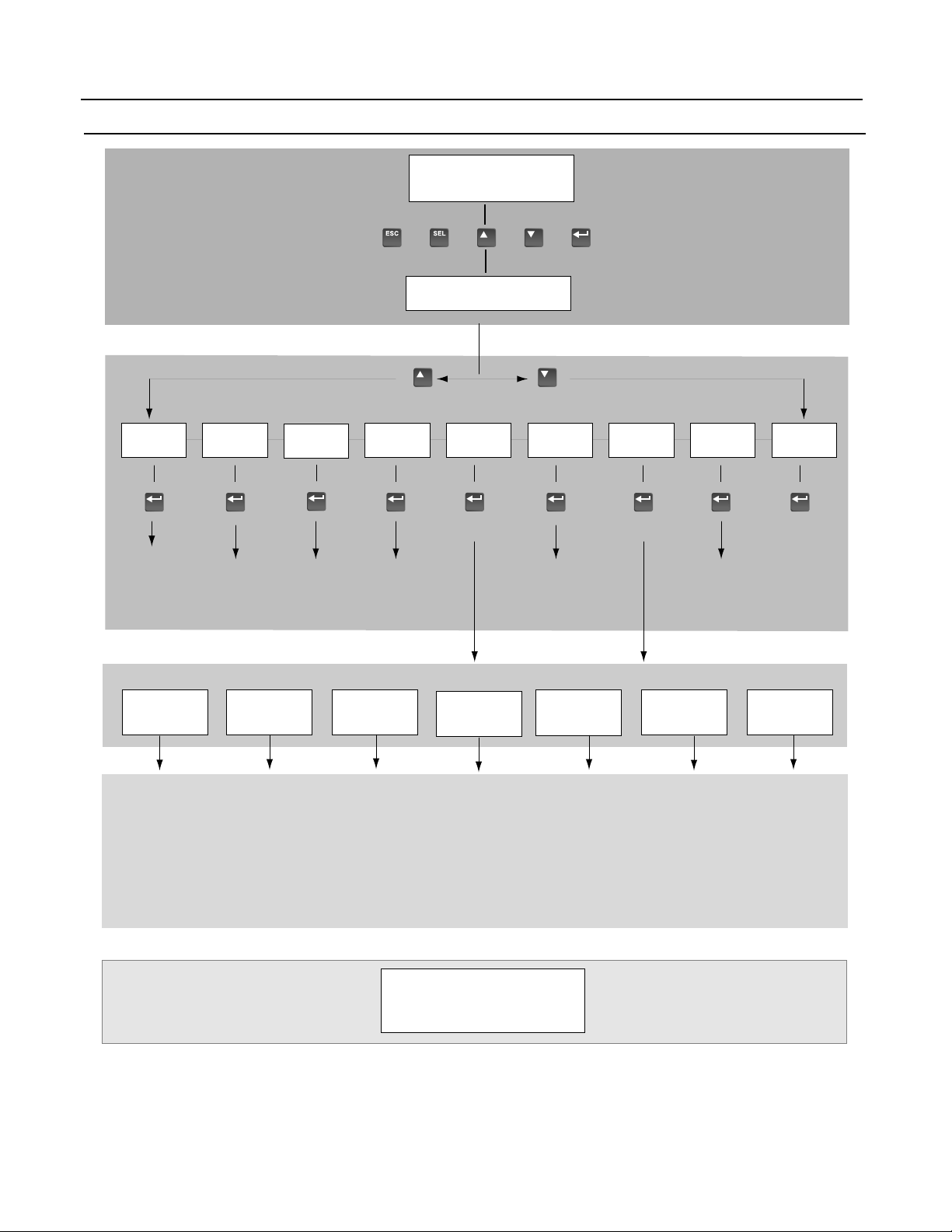
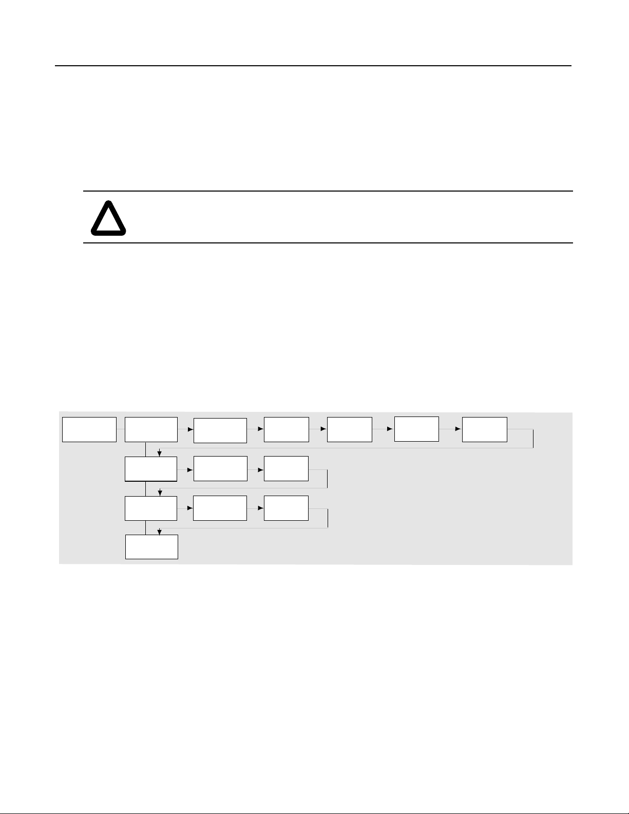
6. From the Status Display, press the Enter key (or any key). “Choose Mode” will be displayed . Pres s the Increment (or
Decrement) key until “Startup is displayed. Press Enter.
Important: All questions can be answered Yes or No. Pressing Enter will select the default (“Y” or “N”). Pressing the
Increment (or Decrement) key will change the selection. Press Enter to select. Choosing “Y” allows you to proceed
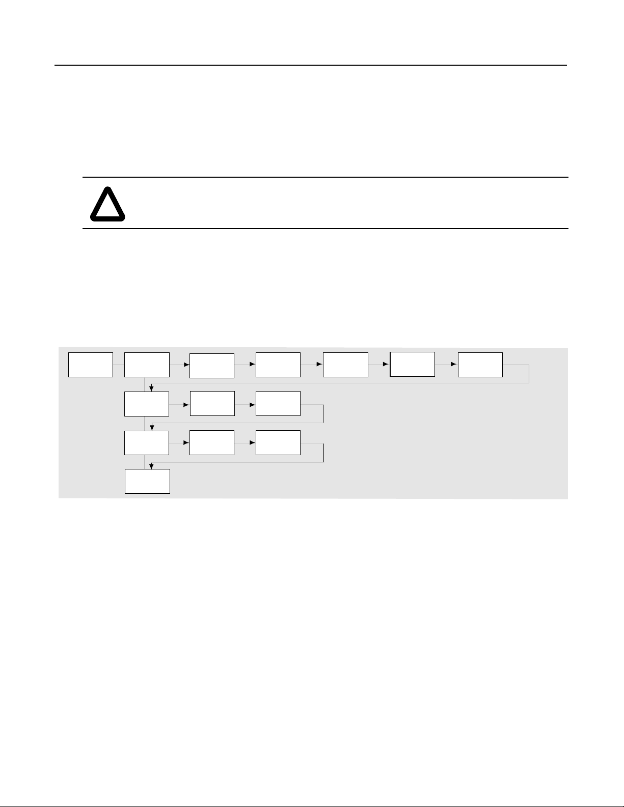
through the step, and choosing “No” will advance you to th e next step . The figure below shows the steps involved.
Startup
Quick Motor
Tune?
No
Configure
Digital?
No
Configure
Analog?
No
Done
Yes
Enter Motor
Data?
Relay
Yes Yes
Output
Inputs Outputs
Yes Yes
Yes Yes Yes Yes
Encoder?
L Option
Regen/
Brake?
Phase
Rotation?
Autotune?
Important: Pleas e note the following:
• The “Startup” mode can be e xit ed at an y time by pressing ESCape until the Status Display i s shown. If you wish
to re-enter the “Startup” mode, simply select “Reset Sequence” to start from the beginning. Selecting “Continue”
allows you to resume from the point where you left off.
• Completing the last action in any step will automatically take you to th e next step.
• Pressing SELect will activate line 2 of the display. This must be done for all values.
• Press the Increment (or Decrement) key to adjust a value (skip if value is correct). Press Enter to store the value
or retain existing value. Pressing Enter again will cause you to move to the next step (parameter)
7. Cycle power to acti v ate changes. This completes the “Assisted Startup” procedure. Depending o n your application, furt her
parameter programming and/or “Advanced Startup” may be required. Refer to the User Manual for details.
4 Publication 1336 IMPACT-5.5ML – May, 1999
Page 5
1336 IMPACT Quick Start Guide
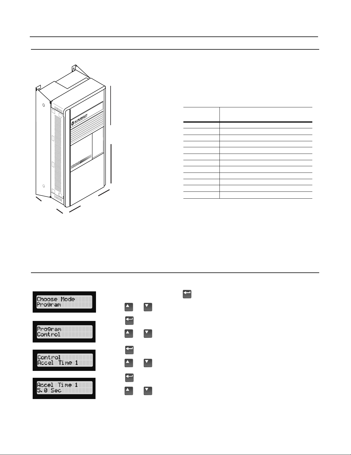
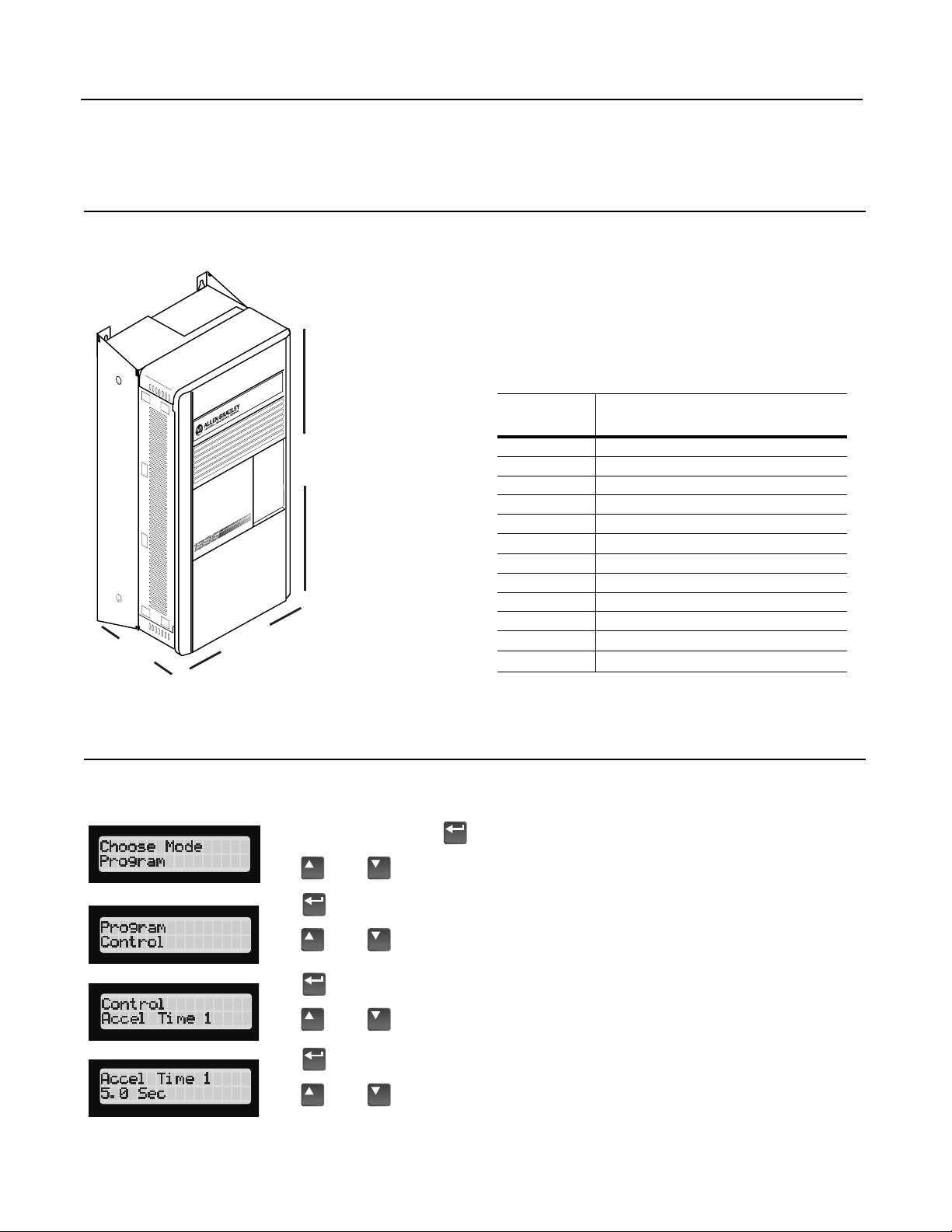
Drive Dimensions
To determine the size of your drive, refer to the following illustration and table.
Depth
HIM Operation
Width
Height
Frame
A1
A2
A3
A4
B
C
D
E-Enclosed
E-Open
F
G
H
➀
Fan height (635.0 (25.00)) not included.
Width x Height x Depth
Millimeters (inches)
215.9 (8.50) x 290.0 (11.42) x 160.0 (6.30)
215.9 (8.50) x 290.0 (11.42) x 180.5 (7.10)
215.9 (8.50) x 290.0 (11.42) x 207.0 (8.15)
260.0 (10.24) x 350.0 (13.78) x 212.0 (8.35)
276.4 (10.88) x 476.3 (18.75) x 225.0 (8.86)
301.8 (11.88) x 701.0 (27.60) x 225.0 (8.86)
381.5 (15.02) x 1240.0 (48.82) x 270.8 (10.66)
511.0 (20.12) x 1498.6 (59.00) x 477.5 (18.80)
511.0 (20.12) x 1498.6 (59.00) x 372.6 (14.67)
762.0 (30.00) x 2286.0 (90.00) x 635.0 (25.00)
762.0 (30.00) x 2387.6 (94.0) x 635.0 (25.00)
1270.0 (50) x 2324.1 (91.50)➀ x 635.0 (25)
Parameter programming or viewing is accomplished through the Program or Display modes shown below.
1. From the Status Display, press to display “Choose Mode.”
2. Press or to display “Program” (or “Display”).
3. Press .
4. Press or until the desired file is displayed.
5. Press .
6. Press or until the desired group is displayed.
7. Press .
8. Press or to scroll to the desired pa rameter.
Publication 1336 IMPACT-5.5ML – May, 1999 5
Page 6
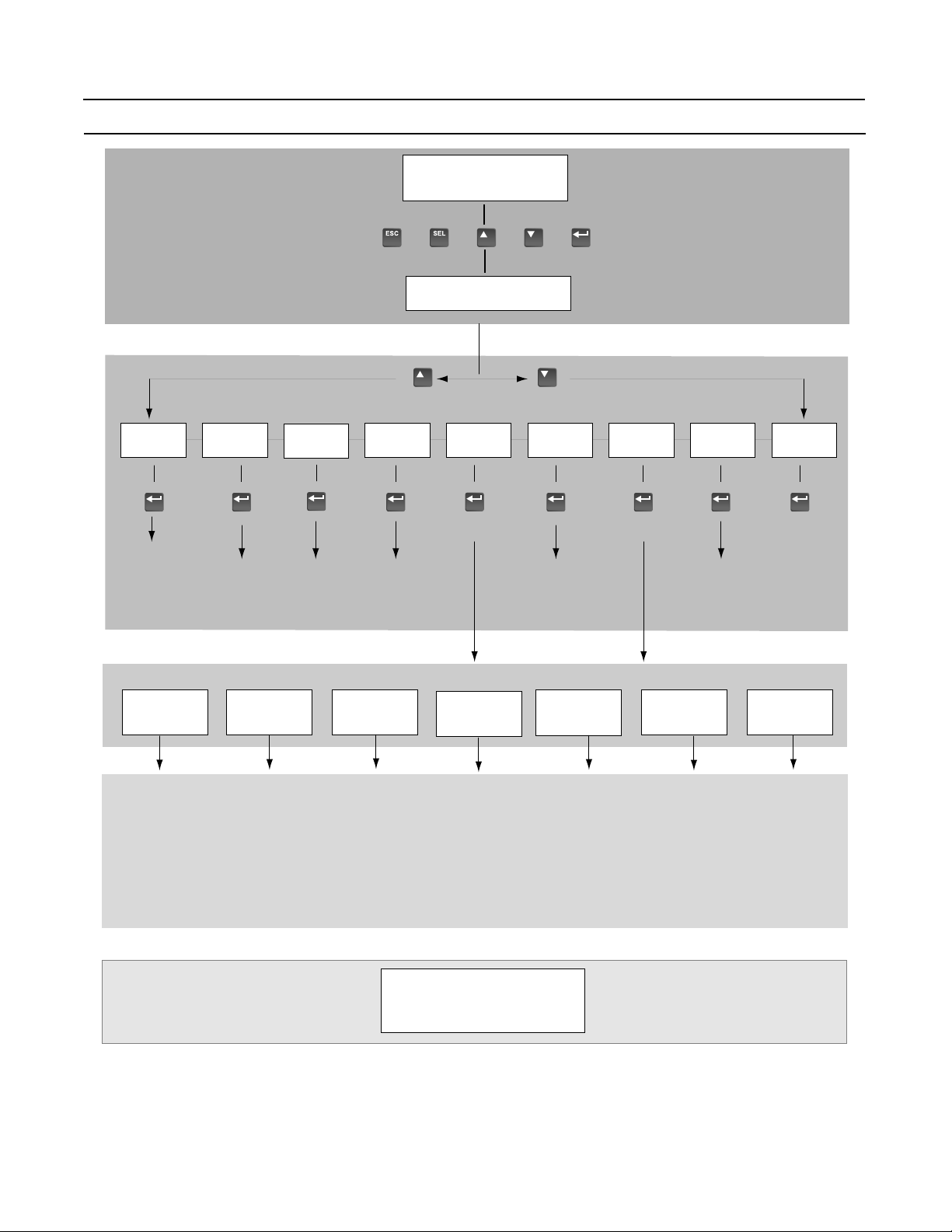
HIM Structure
1336 IMPACT Quick Start Guide
Power-Up and
Status Display
or or or or
Choose Mode
EEProm Search Password Display Process
Save Values
Recall Values
Reset Defaults
Drive to HIM
HIM to Drive
Parameters
Links
Control
Status
Control Logic
Reset Drive1
Fault Queue
Warning Queue
Login
Logout
Modify
Process Display
Program
Operator Level
Mode Level
Link Start Up
Set Links
Clear All Links
Monitor
Motor Status
Drive/Inv Status
SCANport Status
Fault Status
Testpoints
Control
Drive Logic Select
Control Limits
Speed/Torq Mode
Speed Reference
Accel/Decel
Torque Reference
Feedback Device
Speed Feedback
Speed Regulator
Fault Setup
Fault Config
Fault Limits
Test Points
Interface/
Comm
Digital Config
Analog Inputs
Analog Outputs
SCANport Config
SCANport Status
SCANport Analog
Gateway Data In
Gateway Data Out
Parameters
(See Next Page)
Motor/
Inverter
Motor Nameplate
Encoder Data
Inverter
Motor Constants
File Level
Application Autotune
Group Level
Flux Braking
DC Braking/Hold
Max Mtr Current
Fast Flux Up
Start Dwell
Prog Function
Bus Reg/Control
Process Trim
Flying Start
Autotune Setup
Autotune Status
Autotune Results
Drive to HIM
HIM to Drive
Element Level
Publication 1336 IMPACT-5.5ML – May, 1999 6
Page 7

1336 IMPACT Quick Start Guide
Parameters - Files, Groups, and Elements
Name No. Min./Max. Value Name No. Min./Max. Value
Monitor Neg Mtr Cur Lim 73 Calc/0.0%
Motor Status Pos Torque Lim 74 0.0%/Calc
Motor Speed 81 -8 x BMS/+8 x BMS Neg Power Lim 75 Calc/0.0%
Motor Frequency 89 -250.000/+250.000 Hz Regen Power Lim 76 -800.0%/0.0%
Motor Current 83 0.0/6553.5 amps Current Rate Lim 77 Calc/200.0%
Motor Voltage 85 0/+3000 volts Max Mtr Current 195 0/1
Motor Voltage % 234 0/800% Min Speed Limit 215 0.0
Motor Torque % 86 -800.0/+800.0%
Speed/Torq Mode
Motor Flux % 88 12.5/100.0% Spd/Trq Mode Sel 68 0/5
Motor Power% 90 -800.0/+800.0%
Speed Reference
Enc Pos Fdbk Low 227 0/65535 Speed Ref 1 29 -8x/+8xBMS rpm
Enc Pos Fdbk Hi 228 0/65535 Speed Scale 1 30 -3.9999/+3.9999
Int Torque Ref 229 -800/+800% Speed Ref 2 31 -8x/+8xBMS rpm
Drive/Inv Status Speed Ref 3 32 -8x/+8xBMS rpm
DC Bus Voltage 84 0/1000V Speed Ref 4 33 -8x/+8xBMS rpm
Logic Input Sts 14 Bit selection Speed Ref 5 34 -8x/+8xBMS rpm
Drive/Inv Status 15 Bit selection Speed Ref 6 35 -8x/+8xBMS rpm
Drive/Inv Sts 2 196 Bit selection Speed Ref 7 36 -8x/+8xBMS rpm
Run Inhibit Sts 16 Bit selection Speed Scale 7 37 -3.9999/+3.9999
Command Spd Sts 82 -8 x BMS/+8 x BMS Jog Speed 1 38 -8x/+8xBMS rpm
Torque Limit Sts 87 Bit selection Jog Speed 2 39 -8x/+8xBMS rpm
Spd Reg Output 225 -300.0/+300.0%
Accel/Decel
Spd Error 226 -8 x BMS/+8 x BMS Accel Time 1 42 0.0/6553.5 sec
SCANport Status Accel Time 2 43 0.0/6553.5 sec
Dir/Ref Owner 128 Bit selection Decel Time 1 44 0.0/6553.5 sec
Start/Stop Owner 129 Bit selection Decel Time 2 45 0.0/6553.5 sec
Jog1/Jog2 Owner 130 Bit selection S-Curve Percent 47 0.0/100.0%
Ramp/ClFlt Owner 131 Bit selection
Torque Reference
Flux/Trim Owner 132 Bit selection Torque Ref 1 69 -800.0/+800.0%
Fault Status Slave Torque % 70 -200.00/+200.00%
PwrUp Flt Status 219 Bit selection
Feedback Device
Ncfg Flt Status 220 Bit selection Fdbk Device Type 64 1/3
Fault Status 1 221 Bit selection Encoder PPR 8 Calc/20000 ppr
Fault Status 2 222 Bit selection
Speed Feedback
Warning Status 1 223 Bit selection Scaled Spd Fdbk 63 -32767/+32767
Warning Status 2 224 Bit selection Fdbk Filter Sel 65 0/4
Testpoints Fdbk Filter Gain 66 -5.00/+5.00
Test Data 1 92 -32768/+32767 Fdbk Filter BW 67 0.2/900.0 rad/sec
Test Select 1 93 0/65535 Notch Filtr Freq 185 5.0/135.0 Hz
Test Data 2 94 -32768/+32767 Notch Filtr Q 186 2/500
Test Select 2 95 0/65535
Speed Regulator
Control Total Inertia 157 0.01 sec/655.00 sec
Drive Logic Select Spd Desired BW 161 0.00 rad/sec/Calc
Logic Options 17 Bit selections Ki Speed Loop 158 0.0/4095.9
Stop Dwell Time 18 0.0/10.0 sec Kp Speed Loop 159 0.0/200.0
Zero Speed Tol 19 0.0 rpm/8xBMS rpm Kf Speed Loop 160 0.500/1.000
Start Dwell Spd 193 -0.1/+0.1 x BMS Error Filtr BW 162 Calc/1500.0 rad/sec
Start Dwell Time 194 0.0/10.0 sec Droop Percent 146 0.0/25.5%
Control Limits Fault Setup
Rev Speed Limit 40 -6xBMS rpm/0.0 rpm
Fault Config
Fwd Speed Limit 41 0.0 rpm/+6xBMS rpm Fault Select 1 20 Bit selection
Pos Mtr Cur Lim 72 0.0%/Calc Warning Select 1 21 Bit selection
/BMS rpm
7 Publication 1336 IMPACT-5.5ML – May, 1999
Page 8

1336 IMPACT Quick Start Guide
Name No. Min./Max. Value Name No. Min./Max. Value
Fault Config cont. SCANport Config
Fault Select 2 22 Bit Selection SP2 Wire Enable 181 Bit Selection
Warning Select 2 23 Bit Selection SP Enable Mask 124 Bit Selection
Fault Limits Dir/Ref Mask 125 Bit Selection
Absolute Overspd 24 0.0 rpm/BMS rpm Start/Jog Mask 126 Bit Selection
Motor Stall Time 25 0.1/3276.7 sec Clr Flt/Res Mask 127 Bit Selection
Motor Overload % 26 110.0/400.0%
SCANport Status
Line Undervolts 27 10.0/90.0% Dir/Ref Owner 128 Bit selection
Testpoints Start/Stop Owner 129 Bit selection
Test Data 1 92 -32768/+32768 Jog1/Jog2 130 Bit selection
Test Select 1 93 0/65535 Ramp/CIFlt Owner 131 Bit selection
Test Data 2 94 -32768/+32767 Flux/Trim Owner 132 Bit selection
Test Select 2 95 0/65535
SCANport Analog
Interface/Comm SP An In1 Select 133 1/16
Digital Config SP An In1 Value 134 -32767/+32767
Relay Config 114 0/38 SP An In1 Scale 135 -1.000/+1.000
Relay Config 1 115 -800.0/+800.0% Sp An In2 Select 136 1/16
Relay Config 2 187 0/36 Sp An In2 Value 137 -32767/+32767
Relay Setpoint 2 188 800.0/+800.0 Sp An In2 Scale 138 -1.000/+1.000
Relay Config 3 189 0/36 Sp An Output 139 -32767/+32767
Relay Setpoint 3 190 -800.0/+800.0
Gateway Data In
Relay Config 4 191 0/36 Data In A1 140 -32767/+32767
Relay Setpoint 4 192 -800/+800.0% Data In A2 141 -32767/+32767
L Option Mode 116 1/25 Data In B1 142 -32767/+32767
L Option In Sts 117 Bit Selection Data In B2 143 -32767/+32767
Mop Increment 118 0.0/BMS Data In C1 144 -32767/+32767
Mop Value 119 0.0/BSMNA Data In C2 145 -32767/+3276
Pulse In PPR 120 500/2000 Data In D1 146 -32767/+32767
Pulse In Scale 121 0.01/10.00 Data In D2 147 -32767/+32767
Pulse In Offset 122 -BMS/+BMS
Gateway Data Out
Pulse In Value 123 0.0/+8xBMS Data Out A1 148 -32767/+32767
Analog Inputs Data Out A2 149 -32767/+32767
An In 1 Value 96 -32767/+32767 Data Out B1 150 -32767/+32767
An In 1 Offset 97 -19.980/+19.980 volts Data Out B2 151 -32767/+32767
An In 1 Scale 98 -16.000/+16.000 Data Out C1 152 -32767/+32767
An In 1 Filter BW 182 0.0/200.0 rad/sec Data Out C2 153 -32767/+32767
An In 2 Value 99 -32767/+32767 Data Out D1 154 -32767/+32767
An In 2 Offset 100 -19.980/+19.980 volts Data Out D2 155 -32767/+32767
An In 2 Scale 101 -16.000/+16.000
An In2 Filter BW 183 0.0/200.0 rad/sec
mA Input Value 102 -32767/+32767
mA In Offset 103 -32.000/+32.000 mA
mA In Scale 104 -16.00
mA In Filter BW 184 0.0/200.0 rad/sec
Analog Outputs
An Out 1 Value +0 105 -32767/+32767
An Out 1 Offset 106 -20.000/+20.000
An Out 1 Scale 107 -1.000/+1.000
An Out 2 Value 108 -32767/+32767
An Out 2 Offset 109 -19.980/+19.980 volts
An Out 2 Scale 110 -1.000/+1.000
mA Out Value 111 -32767/+32767
mA Out Offset 112 -32.000/+32.000 mA
mA Out Scale 113 -1.000/+1.000
8 Publication 1336 IMPACT-5.5ML – May, 1999
Page 9

1336 IMPACT Quick Start Guide
Name No. Min./Max. Value Name No. Min./Max. Value
Motor Inverter Function Sel 212 0/27
Motor Nameplate Function Output1 213 Varies
Nameplate HP 2 0.2 hp/2000.0 hp Function Output2 214 0/65535
Nameplate RPM 3 1 rpm/1500 rpm Function In9 232 -32767/+32767
Nameplate Amps 4 0.1 amps/Calc Function In 10 233 -32767/+32767
Nameplate Volts 5 75 volts/575 volts
Bus Reg Control
Namplate Hz 6 1.0/250.0 Hz Bus/Brake Option 13 Bit selection
Motor Poles 7 2/40 poles
Process Trim
Service Factor 9 1.00/2.00 PTrim Output 48 -800.0/+800.0%
Encoder Data PTrim Reference 49 -800.0/+800.0%
Encoder PPR 8 Calc/2000 ppr PTrim Feedback 50 -800.0/+800.0%
Inverter PTrim Select 51 Bit selection
PWM Frequency 10 1000 Hz/From drive PTrim Filter BW 52 0.0/240.0 rad/sec
Inverter Amps 11 0.1 amps/From drive PTrim Preload 53 -800.0/+800.0%
Inverter Volts 12 75/575 volts PTrim Ki 54 0.000/16.000
Motor Constants PTrim Kp 55 0.000/16.000
Stator Resistance 166 0.00/100.00% PTrim Lo Limit 58 -800.0/+800.0%
Leak Inductance 167 0.00/100.00% PTrim Hi Limit 59 -800.0/+800.0%
Flux Current 168 0.00/75.00% PTrim Out Gain 60 -8.000/+8.000
Slip Gain 169 0.0/400.0% Max Rev Spd Trim 61 -6 x /0.0 BMS rpm
Motor Poles 7 2/40 poles Max Fwd Spd Trim 62 0.0 rpm/+6xBMS rpm
Application Flying Start
Flux Braking FStart Select 216 0/2
Bus/Brake Option 13 Bit selection FStart Speed 217 P40/P41
DC Braking/Hold Autotune
Bus/Brake Option 13 Bit selection Autotune Setup
DC Brake Current 79 0.0%/Calc Autotune/Dgn Sel 173 Bit selection
DC Brake Time 80 0.0/6553.5 sec Trans Dgn Config 172 Bit selection
400% Mtr Current Autotune Torque 64 250%/100.0%
Max Mtr Current 195 0/1 Autotune Speed 165 0.3 x BMS/BMS
Fast Flux Up Autotune Status
Bus/Brake Option 13 Bit selection Autotune Status 156 Bit selection
Fast Flux Level 78 100.0%/Calc Inverter Dgn 1 174 Bit selection
Start Dwell Inverter Dgn 2 175 Bit selection
Start Dwell Spd 193 -0.1 x / +0.1 x BMS Autotune Errors 176 Bit selection
Start Dwell Time 194 0.0/10.0 sec
Autotune Results
Prog Function Stator Resistance 166 0.00/100.00%
Function In1 198 Varies Leak Inductance 167 0.00/100.00%
Func 1 Mask/Val 199 Varies Flux Current 168 0.00/75.00%
Func 1 Eval Sel 200 0/17 Slip Gain 169 0.0/400%
Function In2 201 Varies Total Inertia 157 0.0/655.00 sec
Func 2 Mask/Val 202 Varies Spd Desired BW 161 0.00/Calc rad/sec
Func 2 Eval Sel 203 0/17
Function In3 204 Varies
Func 3 Mask/Val 205 Varies
Func 3 Eval Sel 206 0/17
Function In4 207 Varies
Function In5 208 Varies
Function In6 209 Varies
Function In7 210 Varies
Function In8 211 Bit selection
Publication 1336 IMPACT-5.5ML – May, 1999 9
Page 10

1336 IMPACT Quick Start Guide
This Page Intentionally Blank
10 Publication 1336 IMPACT-5.5ML – May, 1999
Page 11
1336 IMPACT Kurzanleitung
In dieser Kurzanleitung wird beschrieben, wie Sie d en Frequenzum richt er 133 6 IMPACT inst alli eren , in B etri eb nehmen u nd
Verdrahtung der Netzanschlüsse – TB1
Brückenpositionen
programmieren. Die hierin enthaltenen Informati onen si nd jedoch k ein Ers a tz fü r das Benu tzerhand buch und sind nur für
qualifiziertes FU-Wartungspersonal vorgesehen. Detailli erte Inf ormati onen ü ber andere Anwend ungs aspekte und di e
entsprechenden sicherheitstechnischen Hinweise finden Sie im 1336 IMPACT-Benutzerhandbuch ( Publi kation 1336
IMPACT-5.0).
TE
Erde
TE
(nicht bei allen Antrieben) (nicht bei allen Antrieben)
Erforderliche
Eingangssicherung
Leitung/Vierleiterkanal
Nächstgelegene
Gebäude-Stahlkonstruktion
FU-Netzeingang
R
S
(L1)
(L2)T(L3)
Erforderlicher
Zweigtrennschalter
PE
Erde
PE PE
Wichtig: Überprüfen Sie die Motorisolationsspannung. Wenn
Die Abbildung zeigt Anschlüsse, die für alle FUs gleich sind.
Detaillierte Informationen finden Sie im Benutzerhandbuch.
FU-Ausgang
zum Motor
U
(T1)V(T2)W(T3)
Ferritringkern*
Abschirmung*
* Optional
Motorabschlußwiderstand*
das Kabel über 6,1 m lang ist, ziehen Sie das
Benutzerhandbuch zu Rate.
Dynamische Bremse
DC
DC
+
–
Motorgehäuse
BRK
–
PE
Erde gem. lokalen
Vorschriften
J4 (TB4)
J5
J7 (TB7)
LANGUAGE MODULE
ALLEN-BRADLEY
J10 (TB10)
Baugröße A1 – A4
Publikation 1336 IMPACT-5.5DE – Mai 1999
L-Options-
platinen-Brücke
J2
TB10
TB11
LANGUAGE MODULE
ALLEN-BRADLEY
ESC
SEL
JOG
Alle anderen Baugrößen
Page 12
1336 IMPACT Kurzanleitung
Verdrahtungs-E/A – Baugröße A
Verdrahtungs-E/A – Alle anderen Baugrö ßen
J7 (TB7)
J4 (TB4)
Analogeingang 1
Analogeingang 2
4 bis 20 mA
Impulsquelle
Abschirmung
Abschirmung
Abschirmung
Abschirmung
+
-
+
-
+
-
+
-
1
Bezugspotential
2
3
4
5
Analogausgang 1
6
7
8
Analogausgang 2
9
10
11
12
+10V
-10V
Abschirmung
Abschirmung
Abschirmung
4 bis 20 mA
+
-
+
-
+
-
1
2
3
4
5
6
7
8
9
10
11
12
Gleichstrom-
netzteil*
J10 (TB10)
123456789101112
Stromver-
sorgung
Relais 1
Voreinstellung:
Bei Drehzahl
Aktiviert (in Betrieb)
* Das Netzteil ist nur zur Verwendung
für den FU-Eingang vorgesehen.
Voreinstellung:
Relais 2
Voreinstellung:
Kein Fehler
Relais 3
Voreinstellung:
Keine Warnung (Alarm)
TE
Nicht belegt
Relais 4
TB11
Relais 1
Voreinstellung:
Bei Drehzahl
Stromversorgung
TB10
Gleichstrom-
netzteil
+10V Com -10V
1 2345 6789
Aktiviert (in Betrieb)
+++++++-------
Analogein-
gang 1
Relais 2
Voreinstellung:
SH SH SH SH SH
Analogein-
gang 2
123
10 11 12
4-20 mA
4
6
5
789 10
TE
Nicht belegt
Relais 4 Voreinstellung:
Keine Warnung (Alarm)
Relais 3
Voreinstellung: Kein Fehler
13 14 15 16 17 18 19 20 21 22
Impulsquelle
Analogaus-
gang 1
Analogaus-
gang 2
4-20 mA
2 Publikation 1336 IMPACT-5.5DE – Mai 1999
Page 13
1336 IMPACT Kurzanleitung
L-Optionsplatine
Inbetriebnahme
1
Status
2
Start
3
Start
4
Start
5
Start
6
Start
7
Start
8
Start
9
Start
10
Start
11
Start
12
Vorwärts
13
Vorwärts
14
Vorwärts
15
Vorwärts
16
Vorwärts
17
Start
18
Start
19
Start
20
Start
21
Start
22
Start
23
Vorwärts
24
Vorwärts
25
Vorwärts
26
Vorwärts
27
Start
28
Start
29
Start
30
Vorwärts
Wahl Drz
3
2
1
0
0
0 - Drehzahlref. 1
0
0
1 - Drehzahlref. 2
0
1
0 - Drehzahlref. 3
0
1
1 - Drehzahlref. 4
1
0
0 - Drehzahlref. 5
1
0
1 - Drehzahlref. 6
1
1
0 - Drehzahlref. 7
1
1
1 - Keine Änderung,
letzter Zustand
Stop/Alarm Löschen
Stop/Alarm Löschen
Stop/Alarm Löschen
Stop/Alarm Löschen
Stop/Alarm Löschen
Stop/Alarm Löschen
Stop/Alarm Löschen
Stop/Alarm Löschen
Stop/Alarm Löschen
Stop/Alarm Löschen
Stop/Alarm Löschen
Stop/Alarm Löschen
Stop/Alarm Löschen
Stop/Alarm Löschen
Stop/Alarm Löschen
Stop/Alarm Löschen
Stop/Alarm Löschen
Stop/Alarm Löschen
Stop/Alarm Löschen
Stop/Alarm Löschen
Stop/Alarm Löschen
Stop/Alarm Löschen
Stop/Alarm Löschen
Stop/Alarm Löschen
Stop/Alarm Löschen
Stop/Alarm Löschen
Stop/Alarm Löschen
Stop/Alarm Löschen
Stop/Alarm Löschen
Stop/Alarm Löschen
19 20 21 22 23 24 25 26 27 28 29 30 31 32 33 34 35 36
Status
Rückw/Vorw
Rückw/Vorw
Rückw/Vorw
Rückw/Vorw
Rückw/Vorw
Rückwärts
Rückwärts
Pot.Schritt
Rückwärts
Beschl 1
Rückw Lauf
Rückw Lauf
Rückw Lauf
Rückw Lauf
Rückw Lauf
Rückw/Vorw
Rückw/Vorw
Drz/Drm 3
Drz/Drm 3
Rückwärts
Drz/Drm 3
Rückw Lauf
Rückw Lauf
Rückw Lauf
Rückw Lauf
Rückw/Vorw
Pot.Schritt
Rückwärts
Rückw Lauf
Bezugspotential
Status
Probelauf
Anhalteart
Beschl 2*/1
Pot.Schritt
Probelauf
Vorwärts
Vorwärts
Pot.Abnahme
Vorwärts
Beschl 2
Zentr/Dezentr
Anhalteart
Beschl 2*/1
Pot.Schritt
Zentr/Dezentr
PTrim akt
Fluß aktiv
Drz/Drm 2
Drz/Drm 2
Vorwärts
Drz/Drm 2
PTrim akt
Fluß aktiv
PTrim akt
Probelauf
Pot.Schritt
Pot.Abnahme
Vorwärts
Pot.Schritt
Bezugspotential
Status
Ext.Alarm
Ext.Alarm
Ext.Alarm
Ext.Alarm
Ext.Alarm
Ext.Alarm
Ext.Alarm
Ext.Alarm
Ext.Alarm
Ext.Alarm
Ext.Alarm
Ext.Alarm
Ext.Alarm
Ext.Alarm
Ext.Alarm
Ext.Alarm
Ext.Alarm
Ext.Alarm
Ext.Alarm
Ext.Alarm
Ext.Alarm
Ext.Alarm
Ext.Alarm
Ext.Alarm
Ext.Alarm
Ext.Alarm
Ext.Alarm
Ext.Alarm
Ext.Alarm
Bezugspotential
Status
Wahl Drz 3
Wahl Drz 3
Bremse 2*/1
Pot.Abnahme
Zentr/Dezentr
Probelauf
Wahl Drz 3
Wahl Drz 3
Pot.Schritt
Bremse 1
Wahl Drz 3
Wahl Drz 3
Bremse 2*/1
Pot.Abnahme
Anhalteart
Rampe deak
Rücksetzen
Drz/Drm 1
Drz/Drm 1
Rampe deak
Drz/Drm 1
Rücksetzen
Rücksetzen
Rampe deak
Wahl Drz 3
Pot.Abnahme
Wahl Drz 3
Pot.Schritt
Pot.Abnahme
Encoder B
Encoder NICHT A
Encoder NICHT B
Status
Wahl Drz 2
Wahl Drz 2
Wahl Drz 2
Wahl Drz 2
Wahl Drz 2
Wahl Drz 2
Wahl Drz 2
Wahl Drz 2
Pot.Abnahme
Bremse 2
Wahl Drz 2
Wahl Drz 2
Wahl Drz 2
Wahl Drz 2
Wahl Drz 2
Wahl Drz 2
Wahl Drz 2
PTrim akt
Fluß aktiv
Rücksetzen
Wahl Drz 2
Wahl Drz 2
Wahl Drz 2
Wahl Drz 2
Wahl Drz 2
Wahl Drz 2
Wahl Drz 2
Pot.Abnahme
Wahl Drz 2
Encoder A
+12 V (200 mA max.)
Encoder Bezugspotential
Status
Wahl Drz 1
Wahl Drz 1
Wahl Drz 1
Wahl Drz 1
Wahl Drz 1
Wahl Drz 1
Wahl Drz 1
Wahl Drz 1
Wahl Drz 1
Wahl Drz 1
Wahl Drz 1
Wahl Drz 1
Wahl Drz 1
Wahl Drz 1
Wahl Drz 1
Wahl Drz 1
Wahl Drz 1
Wahl Drz 1
Wahl Drz 1
Wahl Drz 1
Wahl Drz 1
Wahl Drz 1
Wahl Drz 1
Wahl Drz 1
Wahl Drz 1
Wahl Drz 1
Wahl Drz 1
Wahl Drz 1
Wahl Drz 1
3
2
0
0
0
0
0
1
0
1
1
0
1
0
1
1
1
1
Aktivieren
Aktivieren
Aktivieren
Aktivieren
Aktivieren
Aktivieren
Aktivieren
Aktivieren
Aktivieren
Aktivieren
Aktivieren
Aktivieren
Aktivieren
Aktivieren
Aktivieren
Aktivieren
Aktivieren
Aktivieren
Aktivieren
Aktivieren
Aktivieren
Aktivieren
Aktivieren
Aktivieren
Aktivieren
Aktivieren
Aktivieren
Aktivieren
Aktivieren
Aktivieren
Wahl Drz/Drm
1
0 - Null Drehmoment
1 - Drehzahl Strg.
0 - Drehmoment Strg.
1 - Min. Drm/Drz
0 - Max. Drm/Drz
1 - Summe Drm/Drz
0 - Null Drehmoment
1 - Null Drehmoment
Das hier beschriebene Inbetriebnahmeverfahren umfaßt nur die i m 1336 IMPACT „Start“-Modus am häufigst en ei ngest ellt en
Werte. Detailliertere Informationen finden Sie im Benutzerhandbuch.
Die folgenden Anleitungen gelten für Benutzer, die eine Bedieneinheit (HIM) verwenden. Wenn keine Bedieneinheit installiert
ist, sind die entsprechenden externen Befehle und Sig nale erford er lich. F erner wird dav on ausg eg angen, daß di e werkseitig
eingestellten Parameter verwendet werden.
!
!
Publikation 1336 IMPACT-5.5DE – Mai 1999 3
ACHTUNG:
Zur Durchführung der folgenden Schritte muß der FU mit St rom v er sorgt werden. Hierbei
ist zu beachten, daß die Netzspannung anliegen kann. Um der Gefahr eines elektrischen Schlags oder eines
Geräteschadens vorzubeugen, sollten die folg enden Schr it t e nur von q uali fiz iertem Wartungsper sonal
durchgeführt werden. Lesen Sie zuerst die nachstehenden Anleitungen. W enn ein hierin beschriebenes Ereignis
bei der Durchführung dieses Verfahrens ni cht eintritt, fahren Sie nicht fort. Schalten Sie die Stromzufuhr durch
Öffnen des Leistungsschalters aus, und beheben Sie den Fehler.
ACHTUNG:
Um der Gefahr eines elektrischen Schlags bei der Durchführung von Wartungsarbeiten
vorzubeugen, überprüfen Sie, ob die Buskondensatoren entladen wurden. Messen Sie die
Zwischenkreisspannung an der + und - Klemme von TB1. Die Spannung muß Null betragen.
Page 14
1336 IMPACT Kurzanleitung
1. Überprüfen Sie, ob die Netzspannung und die Steuerspannung der FU-Nennleistung entsprechen.
2. Falls eine L-Option installiert wurde, überprüfen Sie, ob die Stopp- und Freigabeeingänge vorhanden sind. Wurde diese
Options nicht installiert, überprüfen Sie, ob die Brücken bei FUs der Baugröße A an den Stiften 3 und 4 sowie 17 und
18 von J5 bzw. bei FUs der Baugröße B und höher von J2 angebracht wurden. Siehe „Brückenpositionen“.
3. Bei Verwendung von Standard-E/A überprüfen Sie, ob die Brücken ordnungsgemäß angebracht wurden.
4. Wurde eine Analogoptionskarte installiert, überprüfen Sie, ob die Parameter ordnungsgemäß konfigur iert sind (siehe
Benutzerhandbuch).
ACHTUNG: Bei allen nachstehend beschriebenen Schritten kann es zur Drehung des Motors kommen.
Um Verletzungen, falscher Drehrichtung bzw. einem Geräteschaden vorzubeugen, lesen Sie alle Schritte
!
genau, und lassen Sie Vorsicht walten.
5. Schalten Sie die Netz- und Steuerspannung ein. Jetzt sollte die LED-Anzeige leuchten und den FU-Status „Gestoppt“
sowie die Ausgangsfrequenz „+0,00 Hz“ anzeigen . Wenn der FU einen Fehler feststellt, wird eine entsprech ende Meldung
eingeblendet. Zeichnen Sie die eingeblend eten In for mationen auf , schalten Sie d ie Stromzu fuh r au s, un d b eheben Sie den
Fehler, bevor Sie fortfahren.
6. Drücken Sie bei eingeblendeter Statusanzeige die Eingabetaste (oder eine beliebige andere Taste). Jetzt wird „Modus
wählen“ eingeblendet. Drücken Sie die Aufwärts- oder Abwärtstaste, bis „Inbetriebnahme“ angezeigt wird. Drücken
Sie die Eingabetaste.
Wichtig: Alle Fragen können mit Ja oder Nein beantwortet werden. Durch Drücken der Eingabetaste wird der
Vorgabewert gewählt („Ja“ oder „Nein“). Durch Drücken der Aufwärts- oder Abwärtstaste wird der Wert geändert drücken Sie die Eingabetaste, um die entsprechende Auswahl anzunehmen. Wenn Sie „Ja“ drücken, fahren Sie mit
dem jeweiligen Schritt fort. Wenn Sie „Nein“ drücken, gelangen Sie zum nächsten Schritt. In der nachfolgenden
Abbildung werden die einzelnen Schritte dargestellt.
Inbetriebnahme
SchnelltuningVerfahren?
Nein
Digital
konfigurieren?
Nein
Analog
konfigurieren?
Nein
Fertig
Ja
Motordaten
eingeben?
Relaisausgang L-Option
Ja Ja
Eingänge Ausgänge
Ja Ja
Ja Ja Ja Ja
Encoder?
Regen./
Bremse?
Phasenrotation?
Autotune?
Wichtig: Bitte die folgenden Hinweise beachten:
• Der Modus „Inbetriebnahme“ kann jederzeit beendet werden, indem die ESC-Taste gedrückt wird, bis
die Statusanzeige erscheint. Soll wieder in den Modus „Inbetriebnahme“ gewechselt werden, einfach
„Rücksetzfolge“ auswählen, um nochmals von vorne zu beginnen. Durch Auswahl von „Weiter“ kann
das Verfahren an dem Punkt wiederaufgenommen werden, an dem es abgebrochen wurde.
• Wenn ein Schritt abgeschlossen ist, gelangen Sie automatisch zum nächsten Schritt.
• Durch Drücken von „Auswählen“ wird Zeile 2 der Anzeige aktiviert. Dies muß für alle Werte erfolgen.
• Mit den Aufwärts- oder Abwärtstasten kann ein bestimmter Wert gewählt werden (Wenn der Wert bereits richtig
ist, diesen Schritt auslassen). Danach die Eingabetaste drücken, u m den Wert zu speichern oder den vo rhandenen
Wert beizubehalten. Durch erneutes Betätigen der Eingabetaste wird zum nächsten Schritt (Parameter)
übergeleitet.
4 Publikation 1336 IMPACT-5.5DE – Mai 1999
Page 15
1336 IMPACT Kurzanleitung
7. Das Gerät aus- und wieder einschalten, um die vorgenommenen Änderungen zu aktivieren. Damit ist das
FU-Abmessungen
Bedieneinheit (HIM)
Baugröße
Breite x Höhe x Tiefe
Millimeter
A1
A2
A3
A4
B
C
D
E (IP20)
E (IP00)
F
G
H
Inbetriebnahmeverfahren beendet. Je nach Anwendung können eine weitere Parameterprogrammierung und/oder
eine erweiterte Inbetriebnahme erforderlich sein. Einzelheiten finden Sie im Benutzerhandbuch.
Ziehen Sie zur Feststellung der Größe des Frequenzumri chter s die fol gende Abbild ung und Tabelle zu Rate.
Tiefe
Breite
Höhe
➀
Lüfterhöhe (635, 0) ni cht inbegriffen
215,9 x 290,0 x 160,0
215,9 x 290,0 x 180,5
215,9 x 290,0 x 207,0
260,0 x 350,0 x 212,0
276,4 x 476,3 x 225,0
301,8 x 701,0 x 225,0
381,5 x 1240,0 x 270,8
511,0 x 1498,6 x 477,5
511,0 x 1498,6 x 372,6
762,0 x 2286,0 x 635,0
762,0 x 2387,6 x 635,0
1270,0 x 2324,1➀ x 635,0
Das Programmieren (oder Lesen) der Parameter erfolgt über den nachfolgend ab gebildet en Pr ogrammi er- bzw. Anzeigemodus.
1. Auf der Statusanzeige drücken, um „Modus wählen“ anzuzeigen.
2. oder drücken, um „Programmieren“ (oder „Anzeigen“) anzuzeigen.
Publikation 1336 IMPACT-5.5DE – Mai 1999 5
3. drücken.
4. oder drücken, bis die gewünschte Datei angezeigt wird.
5. drücken.
6. oder drücken, bis die gewünschte Gruppe angezeigt wird.
7. drücken.
8. oder drücken, um den gewünschten Parameter zu wählen.
Page 16
1336 IMPACT Kurzanleitung
Struktur der Bedieneinheit (HIM)
Inbetriebnahmemodus
und Statusanzeige
oder oder oder oder
Modus wählen
Bedienerebene
Modusebene
EEProm Suchen Kennwort Anzeige Prozeß
Werte speichern
Werte aufrufen
Std. wert rücks.
FU - HIM
HIM - FU
Monitor
Status Motor
Status Antrb/WR
Status SCANport
Status Fehler
Testpunkte
Parameter
Gruppen
Steuerung
Wahl AntriebLog.
Steuerg.Limit
Drehz/Drehm.Mod.
Drehzahlreferenz
Beschl/Brems
Drehm.Referenz
Gerät Meldung
Drehzahlmeldung
Drehz.Steuerung
Status
Steuerlogik
FU1 zurücksetzen
Fehlerwarteschlange
Warnungswarteschlange
Alarme Einricht.
Alarme Konfig.
Alarme Limit
Testpunkte
Anmelden
Abmelden
Ändern
Prozeßanzeige
Komm.
Interface
Digit.Konfig.
Analog Eing.
Analog Ausg.
SCANport Konfig.
SCANport Status
SCANport Analog
Gateway Eing.
Gateway Ausg.
Motor/
Wechselr
Motor Nennwert
Daten Encoder
Wechselrichter
Motor Konst.
Programm
Gruppen
Gruppen einstellen
Alle Gruppen löschen
Applikation Autotune
Flußbremse
GlStr Brms/Hold
Max. Strom Motor
Rasch.Flußaufbau
Startverzögerg
Prog Funktion
Bus Reg/Steuerg
Prozeß-Trim
Flieg. Start
Inbetriebnahme
Datei-Ebene
Gruppenebene
Autotune Einr.
Autotune Status
Autotune Auswrtg
Antr an HIM
HIM an Antr
6 Publikation 1336 IMPACT-5.5DE – Mai 1999
Parameter
(siehe nächste Seite)
Elementebene
Page 17

Publikation 1336 IMPACT-5.5DE – Mai 1999 7
1336 IMPACT Kurzanleitung
Parameter – Dateien, Gruppen und Elemente
Bezeichnung
Nr.
Min./Max. Wert
Bezeichnung
Nr.
Min./Max. Wert
Monitor
Max.Neg.Mtrspnng
73
Kalk/0,0%
Motorstatus
Pos.Drehm.Limit
74
0,0%/Kalk.
Motordrehzahl
81
-8 x BMS/+8 x BMS
Neg.Drehm.Limit
75
Kalk/0,0%
Motorfrequenz
89
-250,000/+250,000 Hz
Reg.Spann.Limit
76
-800,0%/0,0%
Strom Motor
83
0,0/6553,5 A
Max.Stromveränd
77
Kalk/200,0%
Motorspannung
85
0/+3000 V
Max.Strom Motor
195
0/1
Motorspannung %
234
0/800%
Mindestdrehzahl
215
0,0/ BMS U/Min.
Motordrehmom. %
86
-800,0/+800,0%
Drehz/Drehm.Mod
Motorflu ß %
88
12,5/100,0%
Drehz/Drehm Wahl
68
0/5
Motor Leistung %
90
-800,0/+800,0%
Drehzahlreferenz
Enc.Pos.Mldg. niedr
227
0/65535
Drehz.Ref.1
29
-8x/+8xBMS U/Min.
Enc.Pos.Mldg. hoch
228
0/65535
Drehz.Faktor 1
30
-3,9999/+3,9999
Int. Drehmomentref.
229
-800/+800%
Drehz.Ref.2
31
-8x/+8xBMS U/Min.
Status Antrieb/Wechselrichter
Drehz.Ref.3
32
-8x/+8xBMS U/Min.
Spanng.GS-Bus
84
0/1000 V
Drehz.Ref.4
33
-8x/+8xBMS U/Min.
Stat.Log.Eingabe
14
Bitwahl
Drehz.Ref.5
34
-8x/+8xBMS U/Min.
Stat.Antr/Wchslr
15
Bitwahl
Drehz.Ref.6
35
-8x/+8xBMS U/Min.
Stat.Antr/Wslr2
196
Bitwahl
Drehz.Ref.7
36
-8x/+8xBMS U/Min.
Störungsgrund
16
Bitwahl
Drehz.Faktor 7
37
-3,9999/+3,9999
Komm.Drehz.St
82
-8 x BMS/+8 x BMS
Probelauf Drz 1
38
-8x/+8xBMS U/Min.
Drehm.Begr.Stats
87
Bitwahl
Probelauf Drz 2
39
-8x/+8xBMS U/Min.
Drehzahlreg.Ausg.
225
-300,0/+300,0%
Beschl/Brems
Drehz.Alarm
226
-8 x BMS/+8 x BMS
Beschl.dauer 1
42
0,0/6553,5 s
SCANport Status
Beschl.dauer 2
43
0,0/6553,5 s
Richtg./Steuerg.
128
Bitwahl
Bremsdauer 1
44
0,0/6553,5 s
Start/Anh.
129
Bitwahl
Bremsdauer 2
45
0,0/6553,5 s
Probel1/Probel2
130
Bitwahl
Prozent S-Kurve
47
0,0/100,0%
Rampe/Al.Lösch
131
Bitwahl
Drehmomentreferenz
Fluß/Trim
132
Bitwahl
Drehm.Ref. 1
69
-800,0/+800,0%
Fehlerstatus
Drehm. Slave%
70
-200,00/+200,00%
Start Fehler.Stat.
219
Bitwahl
Meldegerät
Neg Fehler.Stat.
220
Bitwahl
Art Meldungsger.
64
1/3
Fehlerstatus 1
221
Bitwahl
Encoder PPU
8
Kalk./20000 ppu
Fehlerstatus 2
222
Bitwahl
Drehzahlmeldung
Warnstatus 1
223
Bitwahl
Drehzhlmld.Faktr
63
-32767/+32767
Warnstatus 2
224
Bitwahl
Wahl Meld.Filter
65
0/4
Testpunkte
Verst.Meld.Filt.
66
-5,00/+5,00
Daten Test 1
92
-32768/+32767
Meld.Filter BB
67
0,2/900,0 rad/s
Wahl Test 1
93
0/65535
Freq.Kerbfilter
185
5,0/135,0 Hz
Daten Test 2
94
-32768/+32767
BereichKerbfiltr
186
2/500
Wahl Test 2
95
0/65535
Drehzahlsteuerung
Steuerung
Gesamtträgheit
157
0,01 s/655,00 s
Wahl Antriebslogik
Bandbr.Regelschw
161
0,00 rad/s/Kalk.
Optionen Logik
17
Bitwahl
Dämpf.i.Reglschw
158
0,0/4095,9
Verzögerg.Anh.
18
0,0/10,0 s
Dämpf.p.Reglschw
159
0,0/200,0
Tol.Nullgeschw.
19
0,0 U/Min/8xBMS U/Min.
Dämpf.f.Reglschw
160
0,500/1,000
Startverz.Drehz
193
-0,1/+0,1 x BMS
Bandbr.Abweichg.
162
Kalk/1500,0 rad/s
Startverz.Dauer
194
0,0/10,0 s
Drosselung in %
146
0,0/25,5%
Steuerungslimits
Alarmeinrichtung
DrehzLimit Rückw
40
-6xBMS U/min./0,0 U/.min.
Alarme Konfig.
Drehz.Limit Vorw
41
0,0 U/Min/+6xBMS U/Min.
Fehlerwahl 1
20
Bitwahl
Max.Pos.Mtrspnng
72
0,0%/Kalk.
Alarmwahl 1
21
Bitwahl
Page 18

8 Publikation 1336 IMPACT-5.5DE – Mai 1999
1336 IMPACT Kurzanleitung
Alarme Konfig. (Forts.)
SCANport Konfig.
Fehlerwahl 2
22
Bitwahl
SCANport 2 Kabel
181
Bitwahl
Alarmwahl 2
23
Bitwahl
SCANPort ein/aus
124
Bitwahl
Alarme Limit
Richtg./Referenz
125
Bitwahl
Drz.absol.übschr
24
0,0 U/Min./BMS U/Min.
Start/Probelauf
126
Bitwahl
Verz.Störung
25
0,1/3276,7 s
Al.Lösch/M.Rücks
127
Bitwahl
Überbelastung %
26
110,0/400,0%
SCANport Status
Netz-Unterspann.
27
10,0/90,0%
Richtg./Referenz
128
Bitwahl
Testpunkte
Start/Anh.
129
Bitwahl
Daten Test 1
92
-32768/+32768
Probel1/Probel2
130
Bitwahl
Wahl Test 1
93
0/65535
Rampe/Al.Lösch
131
Bitwahl
Daten Test 2
94
-32768/+32767
Fluß/Trim
132
Bitwahl
Wahl Test 2
95
0/65535
SCANport Analog
Komm.Interface
Wahl SP.Anal.E1
133
1/16
Digit.Konfig.
Wert SP.Anal.E1
134
-32767/+32767
Relay Konfig 1
114
0/38
Fakt.SP.Anal.E1
135
-1,000/+1,000
Relay Wert 1
115
-800,0/+800,0%
Wahl SP.Anal.E2
136
1/16
Relay Konfig.2
187
0/36
Wert SP.Anal.E2
137
-32767/+32767
Relay Wert 2
188
-800,0/+800,0
Fakt.SP.Anal.E2
138
-1,000/+1,000
Relay Konfig.3
189
0/36
ScP Anal.Ausg.
139
-32767/+32767
Relay Wert 3
190
-800,0/+800,0
Gateway Eing.
Relay Konfig. 4
191
0/36
Daten Eing. A1
140
-32767/+32767
Relay Wert 4
192
-800,0/+800,0%
Daten Eing. A2
141
-32767/+32767
L-Option Modus
116
1/25
Daten Eing. B1
142
-32767/+32767
L-Opt.Eing.Stat.
117
Bitwahl
Daten Eing. B2
143
-32767/+32767
Pot.Schritt
118
0,0/BMS
Daten Eing. C1
144
-32767/+32767
Pot.Wert
119
0,0/BSMNA
Daten Eing. C2
145
-32767/+32767
Pulse Eing.PPU
120
500/2000
Daten Eing. D1
146
-32767/+32767
Pulse Eing.Fakt.
121
0,01/10,00
Daten Eing. D2
147
-32767/+32767
Pulse Eing.Vers.
122
-BMS/+BMS
Gateway Ausg.
Pulse Eing.Wert
123
0,0/+8xBMS
Daten Ausg. A1
148
-32767/+32767
Analogeingänge
Daten Ausg. A2
149
-32767/+32767
Anal.Eing.Wert 1
96
-32767/+32767
Daten Ausg. B1
150
-32767/+32767
Anal.Eing.Vers.1
97
-19,980/+19,980 V
Daten Ausg. B2
151
-32767/+32767
Anal.Eing.Fakt.1
98
-16,000/+16,000
Daten Ausg. C1
152
-32767/+32767
BB.Filtr Anal.E1
182
0,0/200,0 rad/s
Daten Ausg. C2
153
-32767/+32767
Anal.Eing.Wert 2
99
-32767/+32767
Daten Ausg. D1
154
-32767/+32767
Anal.Eing.Vers.2
100
-19,980/+19,980 V
Daten Ausg. D2
155
-32767/+32767
Anal.Eing.Fakt.2
101
-16,000/+16,000
BB.Filtr Anal.E2
183
0,0/200,0 rad/s
mA Eing.Wert
102
-32767/+32767
mA Eing.Vers.
103
-32,000/+32,000 mA
mA Eing.Faktor
104
-16,00
BB.Filtr mA.Eing
184
0,0/200,0 rad/s
Analogausgänge
Anal.Ausg.Wert 1 +0
105
-32767/+32767
Anal.Ausg.Vers.1
106
-20,000/+20,000
Anal.Ausg.Fakt.1
107
-1,000/+1,000
Anal.Ausg.Wert 2
108
-32767/+32767
Anal.Ausg.Vers.2
109
-19,980/+19,980 V
Anal.Ausg.Fakt.2
110
-1,000/+1,000
mA Ausg.Wert
111
-32767/+32767
mA Ausg.Vers.
112
-32,000/+32,000 mA
mA Ausg.Faktor
113
-1,000/+1,000
Bezeichnung
Nr.
Min./Max. Wert
Bezeichnung
Nr.
Min./Max. Wert
Page 19

Publikation 1336 IMPACT-5.5DE – Mai 1999 9
1336 IMPACT Kurzanleitung
Bezeichnung
Nr.
Min./Max. Wert
Bezeichnung
Nr.
Min./Max. Wert
Motorwechselrichter
Eval. Wahl
212
0/27
Motor Nennwert
Ausg.1 Eval
213
Variiert
Nenn-PS
2
0,2 PS/2000,0 PS
Ausg.2 Eval
214
0/65535
Nenn-U/Min
3
1 U/Min./1500 U/Min.
Eing.9 Eval.
232
-32767/+32767
Nenn-Amp.
4
0,1 A/Kalk.
Eing.10 Eval.
233
-32767/+32767
Nenn-Volt
5
75 V/575 V
Bus Reg/Steuerg
Nenn-Hz
6
1,0/250,0 Hz
Opt. Bus/Bremse
13
Bitwahl
Pole d. Motors
7
2/40 Pole
Prozeß-Trim
Servicefaktor
9
1,00/2,00
PTrim Ausgabe
48
-800,0/+800,0%
Daten Encoder
PTrim Referenz
49
-800,0/+800,0%
Encoder PPU
8
Kalk./2000 ppu
PTrim Meldung
50
-800,0/+800,0%
Wechselrichter
PTrim Wahl
51
Bitwahl
PWM-Frequenz
10
1000 Hz/Vom Antrieb
PTrim Filter BB
52
0,0/240,0 rad/s
Amp Wechs.richt
11
0,1 Hz/Vom Antrieb
PTrim Voreinst.
53
-800,0/+800,0%
Volt Wechs.richt
12
75/575 V
PTrim Dämpf.i
54
0,000/16,000
Motor Konst.
PTrim Dämpf.p
55
0,000/16,000
Widerstnd.Stator
166
0,00/100,00%
PTrim Min.
58
-800,0/+800,0%
Indukt.Verlust
167
0,00/100,00%
PTrim Max.
59
-800,0/+800,0%
Flußstrom
168
0,00/75,00%
Verst.PTrim Ausg
60
-8,000/+8,000
Schlupfkorr.
169
0,0/400,0%
Max.Trim Rück.
61
-6 x/0,0 BMS U/Min.
Pole d. Motors
7
2/40 Pole
Max.Trim Vorw.
62
0,0 U/Min/+6xBMS U/Min.
Applikation
Fliegender Start
Flußbremse
Wahl FStart
216
0/2
Opt. Bus/Bremse
13
Bitwahl
Drehz FStart
217
P40/P41
GlStr Brms/Hold
Autotune
Opt. Bus/Bremse
13
Bitwahl
Autotune Einr.
Gleichstrombremse
79
0,0%/Kalk.
Wahl Autot/Diagn
173
Bitwahl
GS.Bremsdauer
80
0,0/6553,5 s
Deakt.TransDiag
172
Bitwahl
400% Mtr.Strom
Drehm.f.Autotest
164
250%/100,0%
Max.Strom Motor
195
0/1
Drehz.f.Autotest
165
0,3 x BMS/BMS
Rasch.Flußaufbau
Autotune Status
Opt. Bus/Bremse
13
Bitwahl
Autotune Status
156
Bitwahl
LimitRschFlßaufb
78
100,0%/Kalk.
WechsR.Diag 1
174
Bitwahl
Startverzögerg
WechsR.Diag 2
175
Bitwahl
Startverz.Drehz
193
-0,1 x / +0,1 x BMS
Autotune-Fehler
176
Bitwahl
Startverz.Dauer
194
0,0/10,0 s
Autotune Auswrtg
Prog Funktion
Widerstnd.Stator
166
0,00/100,00%
Eing.1 Eval
198
Variiert
Indukt.Verlust
167
0,00/100,00%
E1Eval Mske/Wrte
199
Variiert
Flußstrom
168
0,00/75,00%
E1 Eval.Wahl
200
0/17
Schlupfkorr.
169
0,0/400%
Eing.2 Eval
201
Variiert
Gesamtträgheit
157
0,0/655,00 s
E2Eval Mske/Wrte
202
Variiert
Bandbr.Regelschw
161
0,00/Kalk. rad/s
E2 Eval.Wahl
203
0/17
Eing.3 Eval
204
Variiert
E3Eval Mske/Wrte
205
Variiert
E3 Eval.Wahl
206
0/17
Eing.4 Eval.
207
Variiert
Eing.5 Eval.
208
Variiert
Eing.6 Eval.
209
Variiert
Eing.7 Eval.
210
Variiert
Eing.8 Eval.
211
Bitwahl
Page 20

1336 IMPACT Kurzanleitung
Raum für Notizen
10 Publikation 1336 IMPACT-5.5DE – Mai 1999
Page 21

Publikation 1336 IMPACT-5.5DE – Mai 1999 11
1336 IMPACT Kurzanleitung
Page 22

Sie finden uns im Internet unter www.rockwellautomation.com
Rockwell Automation ist weltweit für Sie da und vereint führende Marken der
industriellen Automation. Wir bieten Ihnen Steuerungen von Allen-Bradley,
Antriebskomponenten von Reliance Electric, mechanische Antriebselemente
von Dodge sowie Software-Produkte von Rockwell Software. Rockwell
Automation sichert Ihren Wettbewerbsvorteil durch Flexibilität und mit der
Unterstützung von zahlreichen autorisierten Partnern, Distributoren und
Systemintegratoren weltweit.
WeltweiteHauptverwaltung, 1201 South Second Street, Milwaukee, WI 53204, USA, Tel: (1) 414 382-2000, Fax: (1) 414 382-4444
Hauptverwaltung Europa, 46, Avenue Debroux, 1160 Brüssel, Belgien, Tel: (32) 2 663 06 00, Fax: (32) 2 663 06 40
Hauptverwaltung Deutschland, Düsselberger Straße 15, 42781 Haan-Gruiten, Tel: (49) 2104 9600, Fax: (49) 2104 960121
Verkaufszentrum Schweiz, Hintermattlistraße 3, 5506 Mägenwit, Tel: (41) 62 889 77 77, Fax: (41) 62 889 77 66
Hauptverwaltung Österreich, Bäckermühlweg 1, 4030 Linz, Tel: (43) (732) 38 909 0, Fax: (43) (732) 38 909 61
Publikation 1336 IMPACT-5.5DE – Mai 1999
Copyright 1997 Rockwel l A ut om ation. Gedruckt in den USA
Page 23

Guide de mise en route rapide du variateur 1336 IMPACT
Ce guide de mise en route rapide résume les étapes de base nécessaires à l’installation, au démarrage et à la programmation
du variateur de vitesse c.a. 1336 IMPACT . Les info rmations fou rnies NE PEUVENT EN AUCUN CAS REMPLACER celles
du manuel utilisateur et ne peuvent être utilisées que par le perso nnel technique qualifié. Pour obtenir plus de détails sur les
questions concernant d’autres applications et sur les précautions à prendre, consulter le manuel utilisateur du 1336 IMPACT
(publication 1336 IMPACT-5.0).
Câblage électrique – TB1
Mise à la
terre TE
TE
(N’existe pas sur
tous les variateurs)
Fusibles
d’entrée requis
Conduit/Câble à 4 fils
Mise à la terre du
bâtiment le plus proche
Entrée c.a.
vers variateur
R
S
(L1)
(L2)T(L3)
Organe de
coupure requis
Emplacement des cavaliers
Mise à la
terre PE
PE PE
Important : vérifier le niveau crête d’isolation du moteur. Pour les
Le schéma indique les connexions communes à tous les variateurs.
Consulter le manuel utilisateur pour obtenir de plus amples renseignements.
Sortie variateur
vers moteur
U
(T1)V(T2)W(T3)
* En option
câbles d’une longueur supérieure à 6 mètres (20 pieds),
consulter le manuel utilisateur.
Freinage dynamique
DC
+
Tore mode commun*
Blindage*
Résistance d’atténuation
surtensions*
DC
–
(N’existe pas sur
tous les variateurs)
BRK
–
Bâti
moteur
selon les codes locaux
Mise à la terre PE
J4 (TB4)
J7 (TB7)
J10 (TB10)
Taille A1 – A4
Publication 1336 IMPACT-5.5FR – Mai 1999
J5
LANGUAGE MODULE
ALLEN-BRADLEY
Cavaliers de la
carte en option L
J2
TB10
TB11
LANGUAGE MODULE
ALLEN-BRADLEY
ESC
SEL
JOG
Toutes les autres tailles
Page 24

Guide de mise en route rapide du variateur de vitesse 1336 IMPACT
Câblage Entrées/Sorties (E/S) – Tailles A
Entrée
analogique 1
Entrée
analogique 2
4 à 20 mA
Source
d'impulsions
J7 (TB7)
+
Blindage
+
Blindage
+
Blindage
+
Blindage
J4 (TB4)
1
-
-
-
-
2
3
4
5
6
7
8
9
10
11
12
+10V
Commun
-10V
Blindage
Sortie
analogique 1
Blindage
Sortie
analogique 2
Blindage
4 à 20 mA
+
-
+
-
+
-
1
2
3
4
5
6
7
8
9
10
11
12
Source
d’alimentation
c.c.*
J10 (TB10)
123456789101112
Alimentation
Relais vitesse
atteinte
* Source d’alimentation destinée
uniquement à l’entrée variateur.
Relais
de défaut
Relais
de marche
d'alarme
TE
Borne libre
Relais
Câblage E/S – Toutes les autres tailles
TB11
123
Relais
vitesse
atteinte
Alimentation
TB10
Alim. c.c.
+10V Com -10V
1 2345 6789
+++++++-------
Entrée
analogique 1
Relais de
marche
SH SH SH SH SH
Entrée
analogique 2
4
10 11 12
Entrée
4-20 mA
6
5
789 10
TE
Borne libre
Relais
d'alarme
Relais
de défaut
13 14 15 16 17 18 19 20 21 22
Source
d'impulsions
Sortie
analogique 1
Sortie
analogique 2
Sortie
4-20 mA
2 Publication 1336 IMPACT-5.5FR – Mai 1999
Page 25

Carte en option L
1
Etat
2
Démarrage
3
Démarrage
4
Démarrage
5
Démarrage
6
Démarrage
7
Démarrage
8
Démarrage
9
Démarrage
10
Démarrage
11
Démarrage
12
Marche avant
13
Marche avant
14
Marche avant
15
Marche avant
16
Marche avant
17
Démarrage
18
Démarrage
19
Démarrage
20
Démarrage
21
Démarrage
22
Démarrage
23
Marche avant
24
Marche avant
25
Marche avant
26
Marche avant
27
Démarrage
28
Démarrage
29
Démarrage
30
Marche avant
Sélect. Vit.
3
2
1
0
0
0 - Réf. vitesse 1
0
0
1 - Réf. vitesse 2
0
1
0 - Réf. vitesse 3
0
1
1 - Réf. vitesse 4
1
0
0 - Réf. vitesse 5
1
0
1 - Réf. vitesse 6
1
1
0 - Réf. vitesse 7
1
1
1 - Aucun changement, dernier état
Démarrage
Guide de mise en route rapide du vari ateur de vitesse 1336 IMPACT
Arrêt/RAZ faute
Arrêt/RAZ faute
Arrêt/RAZ faute
Arrêt/RAZ faute
Arrêt/RAZ faute
Arrêt/RAZ faute
Arrêt/RAZ faute
Arrêt/RAZ faute
Arrêt/RAZ faute
Arrêt/RAZ faute
Arrêt/RAZ faute
Arrêt/RAZ faute
Arrêt/RAZ faute
Arrêt/RAZ faute
Arrêt/RAZ faute
Arrêt/RAZ faute
Arrêt/RAZ faute
Arrêt/RAZ faute
Arrêt/RAZ faute
Arrêt/RAZ faute
Arrêt/RAZ faute
Arrêt/RAZ faute
Arrêt/RAZ faute
Arrêt/RAZ faute
Arrêt/RAZ faute
Arrêt/RAZ faute
Arrêt/RAZ faute
Arrêt/RAZ faute
Arrêt/RAZ faute
Arrêt/RAZ faute
Etat
Arr./Av.
Arr./Av.
Arr./Av.
Arr./Av.
Arr./Av.
Arrière
Arrière
Augm. MOP
Arrière
Accél. 1
Marche arr.
Marche arr.
Marche arr.
Marche arr.
Marche arr.
Arr./Av.
Arr./Av.
Vit./Couple 3
Vit./Couple 3
Arrière
Vit./Couple 3
Marche arr.
Marche arr.
Marche arr.
Marche arr.
Arr./Av.
Augm. MOP
Arrière
Marche arr.
19 20 21 22 23 24 25 26 27 28 29 30 31 32 33 34 35 36
Commun
Etat
Impulsions
Type Arrêt
Accél. 2*/1
Augm. MOP
Impulsions
Avant
Avant
Réduct. MOP
Avant
Accél. 2
Local/À dist.
Type Arrêt
Accél. 2*/1
Augm. MOP
Local/À dist.
Valid. Ajust. P
Valid. flux
Vit./Couple 2
Vit./Couple 2
Avant
Vit./Couple 2
Valid. Ajust. P
Valid. flux
Valid. Ajust. P
Impulsions
Augm. MOP
Réduct. MOP
Avant
MOP Incr
Commun
Etat
Faute ext.
Faute ext.
Faute ext.
Faute ext.
Faute ext.
Faute ext.
Faute ext.
Faute ext.
Faute ext.
Faute ext.
Faute ext.
Faute ext.
Faute ext.
Faute ext.
Faute ext.
Faute ext.
Faute ext.
Faute ext.
Faute ext.
Faute ext.
Faute ext.
Faute ext.
Faute ext.
Faute ext.
Faute ext.
Faute ext.
Faute ext.
Faute ext.
Faute ext.
Commun
Etat
Sél. Vit. 3
Sél. Vit. 3
Décél. 2*/1
Réduct. MOP
Local/À dist.
Impulsions
Sél. Vit. 3
Sél. Vit. 3
Augm. MOP
Décél. 1
Sél. Vit. 3
Sél. Vit. 3
Décél. 2*/1
Réduct. MOP
Type Arrêt
Invalid. Rampe
Remise à zéro
Vit./Couple 1
Vit./Couple 1
Invalid. Rampe
Vit./Couple 1
Remise à zéro
Remise à zéro
Invalid. Rampe
Sél. Vit. 3
Réduct. MOP
Sél. Vit. 3
Augm. MOP
Réduct. MOP
Codeur B
Codeur NON A
Etat
Sél. Vit. 2
Sél. Vit. 2
Sél. Vit. 2
Sél. Vit. 2
Sél. Vit. 2
Sél. Vit. 2
Sél. Vit. 2
Sél. Vit. 2
Réduct. MOP
Décél. 2
Sél. Vit. 2
Sél. Vit. 2
Sél. Vit. 2
Sél. Vit. 2
Sél. Vit. 2
Sél. Vit. 2
Sél. Vit. 2
Valid. Ajust. P
Valid. flux
Remise à zéro
Sél. Vit. 2
Sél. Vit. 2
Sél. Vit. 2
Sél. Vit. 2
Sél. Vit. 2
Sél. Vit. 2
Sél. Vit. 2
Réduct. MOP
Sél. Vit. 2
Codeur A
Codeur NON B
+12 V (200 mA maxi.)
Etat
Sél. Vit. 1
Sél. Vit. 1
Sél. Vit. 1
Sél. Vit. 1
Sél. Vit. 1
Sél. Vit. 1
Sél. Vit. 1
Sél. Vit. 1
Sél. Vit. 1
Sél. Vit. 1
Sél. Vit. 1
Sél. Vit. 1
Sél. Vit. 1
Sél. Vit. 1
Sél. Vit. 1
Sél. Vit. 1
Sél. Vit. 1
Sél. Vit. 1
Sél. Vit. 1
Sél. Vit. 1
Sél. Vit. 1
Sél. Vit. 1
Sél. Vit. 1
Sél. Vit. 1
Sél. Vit. 1
Sél. Vit. 1
Sél. Vit. 1
Sél. Vit. 1
Sél. Vit. 1
3
0
0
0
0
1
1
1
1
Codeur commun
Validation
Validation
Validation
Validation
Validation
Validation
Validation
Validation
Validation
Validation
Validation
Validation
Validation
Validation
Validation
Validation
Validation
Validation
Validation
Validation
Validation
Validation
Validation
Validation
Validation
Validation
Validation
Validation
Validation
Validation
Sélection vitesse/couple
2
1
0
0 - Couple zéro
0
1 - Rég. vitesse
1
0 - Rég. Couple
1
1 - Couple/Vit. min.
0
0 - Couple/Vit. max.
0
1 - Somme couple/vit.
1
0 - Couple zéro
1
1 - Couple zéro
La procédure de démarrage concerne seulement le réglage des valeurs les plus courantes ; elle s’effectue via le mode « Mise en
route » [Startup] du 1336 IMPACT. Pour de plus amples renseignements, consulter le manuel utilisateur.
La procédure suivante a été élaborée et rédigée à l’intention des utilisateurs disposant d’un module interface opérateur (IHM).
Les commandes externes et les signaux adéquats doivent être fournis aux utilisateurs sans IHM. Nous partons du principe que
tous les paramètres ont conservé leur valeur par défaut.
A TTENTION :
pour procéder aux étapes suivantes, le variateur doit être mis sous tension. Certaines
tensions sont au potent iel de la ligne d’entrée. Afin d’évite r tout risque d’électrocution ou d’en dommagement
!
de votre équipement, seul le personnel qualifié peut effectuer les procédures suivantes. Il est recommandé
de lire attentivement cette procédure avant de commencer . Si, lors du déroulement de la procédu re, l’un des
événements ne se produit pas, ne continuez pas. Couper l’alimentation électrique en déclenchant le
sectionneur de dérivation et corriger le problème avant de continuer.
A TTENTION :
afin d’éviter tout risque d’électrocution durant le câblage ou l’entretien du variateur de
vitesse, vérifier que la tension des condensateurs de bus a été déchargée. Mesurer la tension du bus c.c. aux
!
Publication 1336 IMPACT-5.5FR – Mai 1999 3
bornes + et - de TB1. Cette tension doit être égale à zéro.
Page 26

Guide de mise en route rapide du variateur de vitesse 1336 IMPACT
1. Vérifier si l’alimentation secteur et l’alimentation de commande correspondent aux valeurs nominales spécifiées pour le
variateur.
2. Si une option L a été installée, vérifier si les contacts Arrêt et Validation sont présents. Si cette option n’a pas été installée,
vérifier si les cavaliers ont été installés sur les broches 3, 4, 17 et 18 sur J5 des variateurs de taille A, ou sur J2 pour les
variateurs de taille B et ultérieurs. Consulter la section Emplacement des cavaliers.
3. En cas d’utilisation d’Entrées/Sorties standard, vé rifier que les cavaliers ont été correctement câblés.
4. Si une option analogique a été installée, vérifier que les paramètres ont été configurés de façon appropriée (consulter le
manuel utilisateur).
A TTENTION : durant chacune des étapes suivantes, le moteur peut se mettre à tourner. Afin d’éviter
tout accident, rotation inappropriée et endommagement de l’équipement, lire attentivement les
!
instructions de chaque étape et procéder avec prudence.
5. Mettre le variateur sous tension, appliquer les tensions de commande. L’affichage à cristaux liquides doit s’allumer et
afficher l’état du variateur « Arrêté » [Stopped] et une fréquence de sortie de « +0,00 Hz ». Si le variateur détecte un
problème, un message relatif au défaut s’affiche. Enregistrer l’information, déconnecter la source d’alimentation et
corriger l’origine du problème avant de continuer.
6. A partir de l’écran d’affichage d’état, appuyer sur la touche Entrée (ou sur toute autre touche). Le message « Choisir
mode » apparaît. Appuyer sur la touche « Incrément » ou « Décrément » jusqu’à ce que le message « Mise en route »
[Startup] s’affiche. Appuyer sur « Entrée » [Enter].
Important : il est possible de répondre à toutes les questions par oui ou par non. Appuyer sur Entrée, puis sélectionner la
valeur par défaut (« O » ou « N ») [Oui ou Non]. On peut modi fier la s élect io n en appu yant sur la t ouche I ncrém ent ( ou
Décrément). Appuyer s ur Entrée pour eff ectuer une sé lection. En cho isissant « O », on accomplit les opérations de l ’étape,
et en choisissant « N » on passe directement à l’étape suivante. Le schéma ci-dessous illustre les différentes étapes.
Mise en route
Réglage rapide
du moteur?
Non
Configuration
numérique?
Non
Configuration
analogique?
Non
Terminé
Oui
Entrer données
moteur?
Sortie
Oui Oui
relais
Entrées Sorties
Oui Oui
Oui Oui Oui Oui
Codeur?
Option L
Régén./
Frein?
Rotation
de phase?
Réglage
auto?
Important : il est recommandé de prendre connaissance des informations suivantes :
• On peut sortir du mode « Mise en route » [Startup] à tout moment en appuyant sur ESC [Échap.] jusqu’à ce que
l’état soit affiché. Pour repasser en mode « Mise en ro ute » , sélectionner simplement « Réinit. séqu ence » [Reset
Sequence] pour recomm encer à p artir d u dé but. Choi sir « Cont inue r » [Cont in ue] permet de reprendr e à l’ endroi t
où l’on s’était arrêté.
• L’exécution de la dernière action d’une étape fait passer automatiquement à l’étape suivante.
• Appuyer sur SEL [sélectionner] pour activer la deuxième ligne de l’affichage. Ce processus doit être suivi pour
toutes les valeurs.
• Appuyer sur la touche Incrément (ou Décrément) pour régler une valeur (sauter cette étape si la valeur est
correcte). Appuyer sur Entrée pour enregistrer la nouvelle valeur ou pour sauvegarder la valeur existante.
Appuyer à nouveau sur Entrée, pour passer à l’étape suivante (paramètre).
7. Mettre hors/sous tension afin d’activer les changements. Cette action met un terme à la procédure de « Mise en route
assistée » [Assisted Startup]. Selon l’application, il peut s’avérer nécessaire d’effectuer d’autres programmations de
paramètres et/ou de « Mise en route évoluée » [Advanced Startup]. Consulter le manuel utilisateur pour obtenir plus de
détails.
4 Publication 1336 IMPACT-5.5FR – Mai 1999
Page 27

Guide de mise en route rapide du vari ateur de vitesse 1336 IMPACT
Dimensions du variateur de vitesse
Afin de déterminer la taille du variateur, consulter l’illustration et le tableau suivants.
Ta ille
Hauteur
Profondeur
Largeur
Fonctionnement avec module interface opérateur (IHM)
Largeur x Hauteur x Profondeur
en millimètres (pouces)
A1
A2
A3
A4
B
C
D
E-fermé
E-ouvert
F
G
H
➀
Hauteur du ventilateur non comprise (635,0 (25,00)).
215,9 (8,50) x 290,0 (11,42) x 160,0 (6,30)
215,9 (8,50) x 290,0 (11,42) x 180,5 (7,10)
215,9 (8,50) x 290,0 (11,42) x 207,0 (8,15)
260,0 (10,24) x 350,0 (13,78) x 212,0 (8,35)
276,4 (10,88) x 476,3 (18,75) x 225,0 (8,86)
301,8 (11,88) x 701,0 (27,60) x 225,0 (8,86)
381,5 (15,02) x 1240,0 (48,82) x 270,8 (10,66)
511,0 (20,12) x 1498,6 (59,00) x 477,5 (18,80)
511,0 (20,12) x 1498,6 (59,00) x 372,6 (14,67)
762,0 (30,00) x 2286,0 (90,00) x 635,0 (25,00)
762,0 (30,00) x 2387,6 (94,0) x 635,0 (25,00)
1270,0 (50) x 2324,1 (91,50)➀ x 635,0 (25)
La programmation ou l’affichage des paramètres s’effectue en mode Programme ou Affichage, comme indiqué ci-dessous.
1. Dans le menu Affichag e, ap puy er sur pour afficher « Choisir Mod e » [C hoo se Mode].
2. Appuyer sur ou sur pour afficher « Programme » [Program] (ou « Affichage »
[Display]).
3. Appuyer sur .
4. Appuyer sur ou sur jusqu’à ce que le fichier désiré s’affiche.
5. Appuyer sur .
6. Appuyer sur ou sur jusqu’à ce que le groupe désiré s’affiche.
7. Appuyer sur .
8. Appuyer sur ou sur pour faire défiler jusqu’au paramètre voulu.
Publication 1336 IMPACT-5.5FR – Mai 1999 5
Page 28

Guide de mise en route rapide du variateur de vitesse 1336 IMPACT
Structure du IHM
EEProm Recherche
Sauvegarde des valeurs
Rappel des valeurs
Réinitialisation
valeurs par défaut
Variateur vers IHM
IHM vers variateur
Paramètres
Liens
Etat de la
commande
Logique de commande
Réinit. variateur 1
File d'atiente défauts
File d'atiete avertissement
Mode Mise en route
et Affichage état
ou ou ou ou
Choisir Mode
Mot de
passe
Ouverlure session
Clôture session
Modifier
Affichage Traitement
Affichage du Traitement
Programme
Niveau de l'opérateur
Niveau mode
Lien Démarrage
Réglage des liens
Annulation tous liens
Mesures
Etat moteur variateur
Etat comm/inv
Etat SCANport
Etat faute
Points réglage
Commandes
Sélect. logique variateur
Limites de contrôle
Mode vit/couple
Réf vitesse
Accél/Décél
Référence couple
Dispos réaction
Réaction vitesse
Régulateur vit
Config. par
défaut
Config défauts
Limites défauts
Points d'essai
Interface/Comm
Config numér
Entrées analog
Sorties analog
Config SCANport
Etat SCANport
Analog SCANport
Ent donn Passer
Sor donn Passer
Paramètres
(voir page suivante)
Moteur/Variateur
Plaque sign motr
Données codeur
Variateur
Constantes du moteur
Application Autoréglage
Freinage flux
Freinage/maint cc
Maxi. cour mtr
Augm rapide flux
Tempor démarr
Fonction prog
Rég/contrôle bus
Rég process
Démarrage de volant
Niveau fichier
Niveau groupe
Config autorégl
Etat autorégl
Résult autorégl
Variateur vers IHM
IHM vers variateur
Niveau élément
6 Publication 1336 IMPACT-5.5FR – Mai 1999
Page 29

Guide de mise en route rapide du vari ateur de vitesse 1336 IMPACT
Paramètres – Fichiers, groupes et éléments
Nom
Mesures
N°
Valeur min./max. Nom
réf.
Lim int nég mot 73 Calc/0,0%
N°
réf.
Valeur min./max.
Etat moteur Lim couple pos 74 0,0%/Calc
Vitesse moteur 81 -8 x BMS/+8 x BMS Lim couple nég 75 Calc/0,0%
Fréquence moteur 89 -250,000/+250,000 Hz Lim courant réac 76 -800,0%/0,0%
Intens moteur 83 0,0/6553,5 ampères Lim taux chg int 77 Calc/200,0%
Tension moteur 85 0/+3000 volts Intens max motr 195 0/1
/
% tension moteur 234 0/800% Limite vit min 215 0,0
% couple moteur 86 -800,0/+800,0%
Mode vitesse/couple
BMS tr/min
% flux moteur 88 12,5/100,0% Sél mde vit/cple 68 0/5
% puiss moteur 90 -800,0/+800,0%
Réf. vitesse
Pos Asser Enc basse 227 0/65535 Réf vitesse 1 29 -8x/+8xBMS tr/min
Pos Asser Enc haute 228 0/65535 Echelle vit 1 30 -3,9999/+3,9999
Réf couple int 229 -800/+800% Réf vitesse 2 31 -8x/+8xBMS tr/min
Etat command/inv Réf vitesse 3 32 -8x/+8xBMS tr/min
Tension bus cc 84 0/1000 volts Réf vitesse 4 33 -8x/+8xBMS tr/min
Etat entrées log 14 Sélection de bit Réf vitesse 5 34 -8x/+8xBMS tr/min
Etat command/inv 15 Sélection de bit Réf vitesse 6 35 -8x/+8xBMS tr/min
Etat comm/inv 2 196 Sélection de bit Réf vitesse 7 36 -8x/+8xBMS tr/min
Etat inv marche 16 Sélection de bit Echelle vit 7 37 -3,9999/+3,9999
Etat vit command 82 -8 x BMS/+8 x BMS Vit pas à pas 1 38 -8x/+8xBMS tr/min
Etat lim couple 87 Sélection de bit Vit pas à pas 2 39 -8x/+8xBMS tr/min
Sortie régul Vit 225 -300,0/+300,0%
Accél/décél
Erreur vitesse 226 -8 x BMS/+8 x BMS Temps accél 1 42 0,0/6553,5 sec
Etat SCANport Temps accél 2 43 0,0/6553,5 sec
Contr dir/réf 128 Sélection de bit Temps décél 1 44 0,0/6553,5 sec
Contr dém/arrêt 129 Sélection de bit Temps décél 2 45 0,0/6553,5 sec
Contr p à p 1/2 130 Sélection de bit % courbe S 47 0,0/100,0%
Contr ramp/réarm 131 Sélection de bit
Référence couple
Contr flux/régl 132 Sélection de bit Réf couple 1 69 -800,0/+800,0%
Etat faute % couple second 70 -200,00/+200,00%
Etat faute démarr 219 Sélection de bit
Syst. réaction
Etat faute Ncfg 220 Sélection de bit Type disp réac 64 1/3
Etat faute 1 221 Sélection de bit Impuls/tr codeur 8 Calc/20000 ppr
Etat faute 2 222 Sélection de bit
Réaction Vitesse
Etat avertissement 1 223 Sélection de bit Réac vit proport 63 -32767/+32767
Etat avertissement 2 224 Sélection de bit S él filtre réac 65 0/4
Points réglage Gain filtre réac 66 -5,00/+5,00
Données essai 1 92 -32768/+32767 Bde pas fil réac 67 0,2/900,0 rad/sec
Sél essai 1 93 0/65535 Fréq fil cpe-bde 185 5,0/135,0 Hz
Données essai 2 94 -32768/+32767 Q filtre cpe-bde 186 2/500
Sél essai 2 95 0/65535
Commandes
Régulateur vit
Inertie totale 157 0,01 sec/655,00 sec
Sélect logique variateur Bde pas vit inv 161 0,00 rad/sec/Calc
Options logiques 17 Sélections de bit Bcle vitesse Ki 158 0,0/4095,9
Arrêt temporis 18 0,0/10,0 sec Bcle vitesse Kp 159 0,0/200,0
Tol vitesse zéro 19 0,0 tr/min/8xBMS tr/min Bcle vitesse Kf 160 0,500/1,000
Vit temp démarr 193 -0,1/+0,1 x BMS Bde pas fil err 162 Calc/1500,0 rad/sec
Tempor démarr 194 0,0/10,0 sec % réduction 46 0,0/25,5%
Limites contrôle
Limite vit ar 40 -6xBMS tr/min/0,0
Config par défaut
Config défauts
tr/min
Publication 1336 IMPACT-5.5FR – Mai 1999 7
Page 30

Guide de mise en route rapide du variateur 1336 IMPACT
x
Nom
Limite vit av 41 0,0 tr/min/+6xBMS
Lim int pos mot 72 0,0%/Calc Sélect avert 1 21 Sélection de bit
Config défaut (suite) Config SCANport
N°
Valeur min./max. Nom
Nom
réf.
Fac éch sor anal 2 110 -1,000/+1,000
tr/min
Valeur sortie mA 111 -32767/+32767
Dépl sortie mA 112 -32,000/+32,000 mA
Fac éch sortie mA 113 -1,000/+1,000
N°
Valeur min./max. Nom
réf.
Sélect défaut 1 20 Sélection de bit
N°
réf.
Valeur min./max.
Sélect défaut 2 22 Sélection de bit Val com 2 fil Sp 181 Sélection de bit
Sélect avert 2 23 Sélection de bit Msq val SCANport 124 Sélection de bit
Limites défaut Masque dir/réf 125 Sélection de bit
Survit absolue 24 0,0 tr/min/BMS tr/min Msq dém/p à p 126 Sélection de bit
Temp bloc moteur 25 0,1/3276,7 sec Msq réar/cnf déf 127 Sélection de bit
% surch moteur 26 110,0/400,0%
Etat SCANport
ss-tens secteur 27 10,0/90,0% Contr dir/réf 128 Sélection de bit
Points réglage Contr dém/arrêt 129 Sélection de bit
Données essai 1 92 -32768/+32768 Contr p à p 1/2 130 Sélection de bit
Sél essai 1 93 0/65535 Contr ramp/réarm 131 Sélection de bit
Données essai 2 94 -32768/+32767 Contr flux/régl 132 Sélection de bit
Sél essai 2 95 0/65535
Interface/comm
Analog SCANport
Sél en an 1 SP 133 1/16
Config numér Val ent an 1 SP 134 -32767/+32767
Config relais 1 114 0/38 Ech ent an 1 SP 135 -1,000/+1,000
Config relais 1 115 -800,0/+800,0% Sél ent an 2 SP 136 1/16
Config relais 2 187 0/36 Val ant an 2 SP 137 -32767/+32767
Pt régl relais 2 188 -800,0/+800,0 Ech ent an 2 SP 138 -1,000/+1,000
Config relais 3 189 0/36 Sort an SCANport 139 -32767/+32767
Pt régl relais 3 190 -800,0/+800,0
Passerelle Entrée données
Config relais 4 191 0/36 Entr données A1 140 -32767/+32767
Pt régl relais 4 192 -800/+800,0% Entr données A2 141 -32767/+32767
Mode option L 116 1/25 Entr données B1 142 -32767/+32767
Etat entr opt L 117 Sélection de bit Entr données B2 143 -32767/+32767
Incrémt pot man 118 0,0/BMS Entr données C1 144 -32767/+32767
Valeur pot man 119 0,0/BSMNA Entr données C2 145 -32767/+32767
Impuls par tr 120 500/2000 Entr données D1 146 -32767/+32767
Fac éch ent imp 121 0,01/10,00 Entr données D2 147 -32767/+32767
Dépl ent impuls 122 -BMS/+BMS
Passerelle Sortie données
Valeur ent impul 123 0,0/+8xBMS Sort données A1 148 -32767/+32767
Entrées analog Sort données A2 149 -32767/+32767
Val ent analog 1 96 -32767/+32767 Sort données B1 150 -32767/+32767
Dépl ent anal 1 97 -19,980/+19,980 volts Sort données B2 151 -32767/+32767
Fac éch ent an 1 98 -16,000/+16,000 Sort données C1 152 -32767/+32767
B ps fil en an 1 182 0,0/200,0 rad/sec Sort données C2 153 -32767/+32767
Val ent analog 2 99 -32767/+32767 Sort données D1 154 -32767/+32767
Dépl ent anal 2 100 -19,980/+19,980 volts Sort données D2 155 -32767/+32767
Fac éch ent an 2 101 -16,000/+16,000
B ps fil en an 2 183 0,0/200,0 rad/sec
Valeur entrée mA 102 -32767/+32767
Dépl entrée mA 103 -32,000/+32,000 mA
Fac éch entr mA 104 -16,00
B pas fil ent mA 184 0,0/200,0 rad/sec
Sorties analog
Valeur sort an 1 105 -32767/+32767
Dépl sort anal 1 106 -20,000/+20,000
Fac éch sort an 1 107 -1,000/+1,000
Valeur sort an 2 108 -32767/+32767
Dépl sort anal 2 109 -19,980/+19,980 volts
N°
réf.
Valeur min./ma
8 Publication 1336 IMPACT-5.5FR – Mai 1999
Page 31

Guide de mise en route rapide du vari ateur de vitesse 1336 IMPACT
Nom
Inverseur du moteur
N°
Valeur min./max. Nom
réf.
Sél fonction 212 0/27
N°
réf.
Valeur min./max.
Plaque signalétique du moteur Sort fonction 1 213 Diffère
Puiss nominale 2 0,2 hp/2000,0 hp Sort fonction 2 214 0/65535
Vitesse nominale 3 1 tr/min/1500 tr/min Entr fonction 9 232 -32767/+32767
Intens nominale 4 0,1 ampères/Calc Entr fonction 10 233 -32767/+32767
Tension nominale 5 75 volts/575 volts
Contrôle rég bus
Fréq nominale 6 1,0/250,0 Hz Option Bus/Frein 13 Sélection de bit
Pôles moteur 7 2/2 pôles
Réglage du processus
Facteur service 9 1,00/2,00 Sort ajust proc 48 -800,0/+800,0%
Données de l'encodeur Réf ajust proc 49 -800,0/+800,0%
Impuls/tr codeur 8 Calc/2000 ppr Réac ajust proc 50 -800,0/+800,0%
Variateur Sélec ajust proc 51 Sélection de bit
Fréquence MLI 10 1000 Hz/à partir du
Bde pas fil aj p 52 0,0/240,0 rad/sec
variat.
Intens inverseur 11 0,1 ampères/à.p.d.variat. Charg ajust proc 53 -800,0/+800,0%
Tens inverseur 12 75/575 volts Ajust proc Ki 54 0,000/16,000
Constantes du moteur Ajust proc Kp 55 0,000/16,000
Résistnce stator 166 0,00/100,00% Lim inf aj proc 58 -800,0/+800,0%
Inductance fuit 167 0,00/100,00% Lim sup aj proc 59 -800,0/+800,0%
Intensité flux 168 0,00/75,00% Gain sort aj pr 60 -8,000/+8,000
Gain glissement 169 0,0/400,0% Régl vit ar max 61 -6 x /0,0 BMS tr/min
Pôles moteur 7 2/40 pôles Régl vit av max 62 0,0 tr/min/+6xBMS
tr/min
Applications
Démarrage volant
Freinage du flux Sél démarr volant 216 0/2
Option bus/frein 13 Sélection de bit Vit démarr volant 217 P40/P41
Maintien de freinage cc
Autoréglage
Option bus/frein 13 Sélection de bit Config autoréglage
Int freinage cc 79 0,0%/Calc Sél autorégl/diag 173 Sélection de bit
Temps frein cc 80 0,0/6553,5 sec Conf diag trans 172 Sélection de bit
Intensité moteur 400% Couple autorégl 164 250%/100,0%
Intens max motr 195 0/1 Vitesse autorégl 165 0,3 x BMS/BMS
Augmentation rapide flux Etat autoréglage
Option bus/frein 13 Sélection de bit Etat autoréglage 156 Sélection de bit
Niv flux rapide 78 100,0%/Calc Diag invers 1 174 Sélection de bit
Temporiastion démarrage Diag invers 2 175 Sélection de bit
Vit temp démarr 193 -0,1 x / +0,1 x BMS Erreurs autorégl 176 Sélection de bit
Tempor démarr 194 0,0/10,0 sec
Résultat autoréglage
Fonction prog Résistnce stator 166 0,00/100,00%
Entr fonction 1 198 Diffère Inductance fuit 167 0,00/100,00%
Masq/val fonct 1 199 Diffère Intensité flux 168 0,00/75,00%
Sél éval fonct 1 200 0/17 Gain glissement 169 0,0/400%
Entr fonction 2 201 Diffère Inertie totale 157 0,0/655,00 sec
Masq/val fonct 2 202 Diffère Bde pas vit inv 161 0,00/Calc rad/sec
Sél éval fonct 2 203 0/17
Entr fonction 3 204 Diffère
Masq/val fonct 3 205 Diffère
Sél éval fonct 3 206 0/17
Entr fonction 4 207 Diffère
Entr fonction 5 208 Diffère
Publication 1336 IMPACT-5.5FR – Mai 1999 9
Page 32

Guide de mise en route rapide du variateur de vitesse 1336 IMPACT
Nom
N°
Valeur min./max. Nom
réf.
Entr fonction 6 209 Diffère
Entr fonction 7 210 Diffère
Entr fonction 8 211 Sélection de bit
Page intentionnellement laissée en blanc
N°
réf.
Valeur min./max.
10 Publication 1336 IMPACT-5.5FR – Mai 1999
Page 33

Guide de mise en route rapide du vari ateur de vitesse 1336 IMPACT
Publication 1336 IMPACT-5.5FR – Mai 1999 11
Page 34

Worldwide representation.
Allen-Bradley, a Rockwell Automation Business, has been helping its customers improve
productivity and quality for more than 90 years. We design, manufacture and support a broad
range of automation products worldwide. They include logic processors, power and motion
control devices, operator interfaces, sensors and a variety of software. Rockwell is one of
the world’s leading technology companies.
Argentina • Aust ralia • Aust ria • Bahrain • Belgium • Brazil • Bulgaria • Canada • Chile • China, PRC • Colombia • Costa Rica • Croatia • Cyprus • Czech Republic
Denmark• Ecuador • Egypt • El Salvador • Finland • Fran c e • Germany • Greece • Guatemala • Honduras • Hong Kong • Hungary • Iceland • India • Indonesia • Ireland
Israel • Italy• Jamaica • Japan • Jordan • Korea • Kuwa it • Lebanon • Malaysia • Mexico • Netherlands • New Zealand • Norway • Pakistan • Per u • Philippines • Pol an d
•
Portugal • Puerto Rico• Qatar • Romania • Russia-CIS • Saudi Arabia • Singapore • Slovakia • Slovenia • South Africa, Republic • Spain • Sweden • Switzerland • Ta i wa n
•
Thailand • Turkey • United Arab Emirates • United Kingdom • United States • Uruguay • Venezuela • Yugoslavia
•
Allen-Bradley Headquarters, 1201 South Second Street, Milwaukee, WI 53204 USA, Tel: (1) 414 382-2000 Fax: (1) 414 382-4444
Publication 1336 IMPACT-5.5FR – Mai 1999
Copyright 1997 Rockwell Automation. Printed in
•
Page 35

1336 IMPACT Guida all’avviamento rapido
Questa Guida all’avviamento rapido riassume le operazioni di base nec essarie per installare, avv iare e p rog rammar e l’inver ter
CA a frequenza variabile 1336 IMPACT. Le informazioni qui contenute NON sostituiscono il Manuale dell’utente e sono
rivolte esclusivamente al personale qualificato per la manutenzione dell’inverter. Per informazioni dettagliate su altre
considerazioni per l’uso dell’inverter e le relative precauzioni, consultare il Manuale dell’utente di 1336 IMPACT
(pubblicazione 1336 IMPACT-5.0).
Cablaggio – TB1
Massa
TE
TE
(non su tutti gli inverter) (non su tutti gli inverter)
Fusibili di
ingresso necessari
Cavo a 4 fili/ guaina protettiva
Struttura d’acciaio
dell’edificio più vicina
(L1)
Scollegamento necessario
del circuito di diramazione
Posizione dei ponticelli
Ingresso CA
all’inverter
R
S
(L2)T(L3)
Massa
PE
PE PE
Importante: verificare il valore nominale della tensione di picco per
Il diagramma mostra i collegamenti comuni a tutti gli inverter.
Riferirsi al manuale dell'utente per ulteriori informazione.
Uscita CA
al motore
U
(T1)V(T2)W(T3)
Nucleo modo comune*
Schermo*
* Opzionale
il sistema di isolamento del motore. Per cavi lunghi più
di 6,1 metri, consultare il Manuale dell’utente.
Freno dinamico
DC
+
Terminatore
del motore*
DC
–
BRK
–
Telaio del motore
Massa PE -
leggi locali
J4 (TB4)
J7 (TB7)
ALLEN-BRADLEY
J10 (TB10)
Telai A1 – A4
Pubblicazione 1336 IMPACT-5.5IT – maggio 1999
J5
LANGUAGE MODULE
Ponticelli scheda
opzione L
J2
TB10
TB11
LANGUAGE MODULE
ALLEN-BRADLEY
ESC
SEL
JOG
Tutti gli altri telai
Page 36

1336 IMPACT Guida all’avviamento rapido
Cablaggio I/O – Telai A
Ingresso
analogico 1
Ingresso
analogico 2
da 4 a 20 mA
Sorgente
impulsi
Schermo
Schermo
Schermo
Schermo
J7 (TB7)
+
-
+
-
+
-
+
-
1
2
3
4
5
6
7
8
9
10
11
12
J4 (TB4)
+10V
Com
-10V
Schermo
Uscita
analogica 1
Schermo
Uscita
analogica 2
Schermo
da 4 a 20 mA
1
2
3
4
+
-
+
-
+
-
5
6
7
8
9
10
11
12
Alimentazione
*
CC
J10 (TB10)
123456789101112
Alimenta-
zione
Relè 1
Predefinito: a velocità
Predefinito: attivato
* L’alimentazione viene usata
solamente per l’ingresso dell’inverter.
Relè 3
Predefinito:
Relè 2
(Marcia)
nessun guasto
Relè 4
Predefinito:
nessun avviso
(Allarme)
TE
Azzeramento
tensione
Cablaggio I/O – Tutti gli altri telai
TB11
Relè 1
Predefinito:
a velocità
Alimentazione
TB10
Alimentazione
CC
+10V Com -10V
1 2345 6789
attivato (Marcia)
+++++++-------
Ingresso
analogico 1
Relè 2
Predefinito:
SH SH SH SH SH
Ingresso
analogico 2
123
10 11 12
Ingresso
4-20 mA
4
6
5
789 10
TE
Azzeramento
tensione
Relè 4 Predefinito:
nessun avviso (Allarme)
Relè 3 Predefinito:
nessun guasto
13 14 15 16 17 18 19 20 21 22
Sorgente
impulsi
Uscita
analogica 1
Uscita
analogica 2
Uscita
3-20 mA
2 Pubblicazione 1336 IMPACT-5.5IT – maggio 1999
Page 37

Scheda opzione L
1
Stato
2
Avvio
3
Avvio
4
Avvio
5
Avvio
6
Avvio
7
Avvio
8
Avvio
9
Avvio
10
Avvio
11
Avvio
12
Marcia/Avanti
13
Marcia/Avanti
14
Marcia/Avanti
15
Marcia/Avanti
16
Marcia/Avanti
17
Avvio
18
Avvio
19
Avvio
20
Avvio
21
Avvio
22
Avvio
23
Marcia/Avanti
24
Marcia/Avanti
25
Marcia/Avanti
26
Marcia/Avanti
27
Avvio
28
Avvio
29
Avvio
30
Marcia/Avanti
Sel. velocità
3
2
1
0
Rif vel 1
0
0 -
0
1 -
Rif vel 2
0
0
1
0 -
Rif vel 3
0
1
1 -
Rif vel 4
1
0
0 -
Rif vel 5
1
0
1 -
Rif vel 6
1
1
0 -
Rif vel 7
1
1
1 -
Nessun cambio, ultima velocità
1336 IMPACT Guida all’avviamento rapido
Stop/Elimina Guasto
Stop/Elimina Guasto
Stop/Elimina Guasto
Stop/Elimina Guasto
Stop/Elimina Guasto
Stop/Elimina Guasto
Stop/Elimina Guasto
Stop/Elimina Guasto
Stop/Elimina Guasto
Stop/Elimina Guasto
Stop/Elimina Guasto
Stop/Elimina Guasto
Stop/Elimina Guasto
Stop/Elimina Guasto
Stop/Elimina Guasto
Stop/Elimina Guasto
Stop/Elimina Guasto
Stop/Elimina Guasto
Stop/Elimina Guasto
Stop/Elimina Guasto
Stop/Elimina Guasto
Stop/Elimina Guasto
Stop/Elimina Guasto
Stop/Elimina Guasto
Stop/Elimina Guasto
Stop/Elimina Guasto
Stop/Elimina Guasto
Stop/Elimina Guasto
Stop/Elimina Guasto
Stop/Elimina Guasto
19 20 21 22 23 24 25 26 27 28 29 30 31 32 33 34 35 36
Stato
Inversa/Avanti
Inversa/Avanti
Inversa/Avanti
Inversa/Avanti
Inversa/Avanti
Inversa
Inversa
Incr. MOP
Inversa
Accel 1
Marcia inversa
Marcia inversa
Marcia inversa
Marcia inversa
Marcia inversa
Inversa/Avanti
Inversa/Avanti
Vel/Coppia 3
Vel/Coppia 3
Inversa
Vel/Coppia 3
Marcia inversa
Marcia inversa
Marcia inversa
Marcia inversa
Inversa/Avanti
Incr. MOP
Inversa
Marcia inversa
Comune
Stato
Impulsi
Tipo arresto
Accel 2*/1
Incr. MOP
Impulsi
Avanti
Avanti
Decr. MOP
Avanti
Accel 2
Loc/Rem
Tipo arresto
Accel 2*/1
Incr. MOP
Loc/Rem
Attiva PTrim
Attiva Flusso
Vel/Coppia 2
Vel/Coppia 2
Avanti
Vel/Coppia 2
Attiva PTrim
Attiva Flusso
Attiva PTrim
Impulsi
Incr. MOP
Decr. MOP
Avanti
Incr. MOP
Comune
Stato
Gsto Est
Gsto Est
Gsto Est
Gsto Est
Gsto Est
Gsto Est
Gsto Est
Gsto Est
Gsto Est
Gsto Est
Gsto Est
Gsto Est
Gsto Est
Gsto Est
Gsto Est
Gsto Est
Gsto Est
Gsto Est
Gsto Est
Gsto Est
Gsto Est
Gsto Est
Gsto Est
Gsto Est
Gsto Est
Gsto Est
Gsto Est
Gsto Est
Gsto Est
Comune
Codificatore B
Codificatore NON A
Stato
Sel vel 3
Sel vel 3
Decel 2*/1
Decr. MOP
Loc/Rem
Impulsi
Sel vel 3
Sel vel 3
Incr. MOP
Decel 1
Sel vel 3
Sel vel 3
Decel 2*/1
Decr. MOP
Tipo arresto
Dis Rampa
Azzera
Vel/Coppia 1
Vel/Coppia 1
Dis Rampa
Vel/Coppia 1
Azzera
Azzera
Dis Rampa
Sel vel 3
Decr. MOP
Sel vel 3
Incr. MOP
Decr. MOP
Codificatore A
Codificatore NON B
Stato
Sel vel 2
Sel vel 2
Sel vel 2
Sel vel 2
Sel vel 2
Sel vel 2
Sel vel 2
Sel vel 2
Decr. MOP
Decel 2
Sel vel 2
Sel vel 2
Sel vel 2
Sel vel 2
Sel vel 2
Sel vel 2
Sel vel 2
Attiva PTrim
Attiva Flusso
Azzera
Sel vel 2
Sel vel 2
Sel vel 2
Sel vel 2
Sel vel 2
Sel vel 2
Sel vel 2
Decr. MOP
Sel vel 2
+12V 1200mA max
Codificatore comune
Stato
Sel vel 1
Sel vel 1
Sel vel 1
Sel vel 1
Sel vel 1
Sel vel 1
Sel vel 1
Sel vel 1
Sel vel 1
Sel vel 1
Sel vel 1
Sel vel 1
Sel vel 1
Sel vel 1
Sel vel 1
Sel vel 1
Sel vel 1
Sel vel 1
Sel vel 1
Sel vel 1
Sel vel 1
Sel vel 1
Sel vel 1
Sel vel 1
Sel vel 1
Sel vel 1
Sel vel 1
Sel vel 1
Sel vel 1
3
2
0
0
0
0
0
1
0
1
1
0
1
0
1
1
1
1
Attiva
Attiva
Attiva
Attiva
Attiva
Attiva
Attiva
Attiva
Attiva
Attiva
Attiva
Attiva
Attiva
Attiva
Attiva
Attiva
Attiva
Attiva
Attiva
Attiva
Attiva
Attiva
Attiva
Attiva
Attiva
Attiva
Attiva
Attiva
Attiva
Attiva
Selezione Vel/Coppia
1
Coppia zero
0 1 -
Reg vel
0 -
Reg coppia
1 -
Coppia/vel Min
0 -
Coppia/vel Max
1 -
Tot Coppia/vel
0 -
Coppia zero
1 -
Coppia zero
Avviamento
Questa procedura di avviamento illustra solamente i valo ri regolati più di frequente usando la modalità “Avviamento”
dell’inverter 1336 IMPACT. Per informazioni dettagliate, consultare il Manuale dell’utente.
La procedura che segue è concepita per gli utenti che hanno installato il Modulo di interfaccia operatore (HIM). Gli utenti
senza HIM dovranno fornire i rispettivi comandi e segnali esterni. Si presume inoltre che tutti i parametri siano sulle
impostazioni predefinite di fabbrica.
ATTENZIONE:
tensioni presenti sono al potenziale della linea in entrata. Per evitare il rischio di scoss a elettrica o danni
!
all’unità, la procedura segu ente deve essere eseguita solamente da pers onale qualificato per la manute nzione
dell’inverter. Leggere e capire l’intera procedura prima di iniziare. Se un evento non si verifica durante
l’esecuzione della procedura, NON CONTINUARE. Interrompere l’alimentazione dell’inverter aprendo il
dispositivo di scollegamento del circuito di diramazione e correggere il problema prima di continuare.
A TTENZIONE:
o durante la manutenzione dell’inverter, accertarsi che sia stata scaricata la tensione sui condensatori del
!
Pubblicazione 1336 IMPACT-5.5IT – maggio 1999 3
bus. Misurare la tensione CC del bus e i terminali + e - di TB1. La tensione deve essere zero
per eseguire le seguenti operazioni è necessario che l’inverter sia acceso. Alcune delle
per evitare il rischio di scossa elettrica mentre si effettuano i collegamenti dei fili elettrici
Page 38

1336 IMPACT Guida all’avviamento rapido
1. Verificare che la potenza CA di rete e la potenza dei controlli coincidano con la potenza nominale dell’inverter.
2. Se è installata l’opzione L, verificare che siano presenti gli ingressi dei d ispositivi di blocco Arresto e Attiva. Se questa
opzione non è installata, controllare che i ponticelli siano installati sui piedini 3 e 4, 17 e 18 di J5 sugli inverter Telaio A,
oppure J2 sugli inverter Telaio B e superiore. Vedere Posizione dei ponticelli.
3. Se viene usato un I/O standard, verificare che i ponticelli siano collegati correttamente.
4. Se è installata l’Opzione Analogica, verificare che i parametri siano correttamente configurati (vedere il Manuale
dell’utente).
ATTENZIONE: in tutte le operazioni seguenti, può verificarsi la rotazione del motore. Per proteggersi
da potenziali infortuni, rotazione scorretta e possibili danni all’unità, leggere attentamente ogni operazione
!
ed eseguirla con cautela.
5. Applicare la potenza CA e le tensioni dei controlli all’inverter. Il display a cristalli liquid i dov rebbe accendersi e
visualizzare la condizione di “Arrestato” dell’inverter ed una frequenza di uscita di “+0,00 Hz”. Se l’inverter rileva
un guasto, il display mostra informazioni relative al guasto. Prendere nota di tali informazioni, rimuovere la potenza e,
prima di continuare, correggere il guasto.
6. Dallo schermo della condizione dell’inverter, premere il tasto Invio (o un tasto qualsiasi). Viene visualizzato “Scegli
modalità”. Premere il tasto Incrementa (o Decrementa) fino a quando appare “Avvio”. Premere Invio.
Importante: a tutte le domande si risponde Sì o No. Premendo Invio viene selezionata la risposta predefinita
(“S” o “N”). Premendo il tasto Incrementa (o Decrementa) la selezione viene cambiata. Premere Invio per
selezionare. Selezionando “S” si può procedere con l’operazione; selezionando “N” si passa all’operazione
successiva. La figura qui sotto mostra la sequenza delle operazioni.
Avvio
Autoregolazione
rapida del
motore?
No
Configurazione
digitale?
No
Configurazione
analogica?
No
Esci
Immettere
Sì
dati motore?
Uscita relè Opzione L
Sì Sì
Ingressi Uscite
Sì Sì
Sì Sì Sì Sì
Codificatore?
Rigen/
Freno?
Rotazione
fase?
Autoregolazione
automatica?
Importante: notare quanto segue:
• È possibile uscire dalla modalità “Avvio” in qualsiasi momento premendo ESC fino a quando appare Display
Stato. Se si desidera passare di nuovo alla modalità “Avvio”, selezionare “Azzera sequenza” per ricominciare
dall’inizio. Selezionando “Continua” è possibile riprendere l’operazione dal punto in cui è stata interrotta.
• Il completamento dell’ultima azione di qualsiasi operazione produce il passaggio all’operazione successiva.
• Premendo SEL viene attivata la riga 2 del display. Questo deve essere fatto per tutti i valori.
• Premere il tasto Incrementa (o Decrementa) per regolare un valore (saltare se il valore è quello corretto) . Premere
Invio per memorizzare il nuovo valore o per conservare il valore esistente. Premendo di nuovo Invio si passa
all’operazione successiva (parametro).
7. Per rendere efficaci i cambiamenti, togliere e rinviare alimentazione. Con ciò si conclude la procedura “Avviamento
guidato”. A seconda della propria applicazione, può darsi sia necessaria una ulteriore programmazione di parametri e/o
la procedura “Avviamento avanzato”. Per informazioni, vedere il Manuale dell’utente.
4 Pubblicazione 1336 IMPACT-5.5IT – maggio 1999
Page 39

1336 IMPACT Guida all’avviamento rapido
Dimensioni dell’inverter
Per determinare la dimensione del proprio inverter, fare riferimento alla figura e alla tabella seguenti.
Telaio
Altezza
E-Con custodia
E-Aperto
Profondità
Larghezza
➀
L’altezza del ventilatore (635 mm) non è inclusa.
Funzionamento del Modulo di Interfaccia Operatore (HIM)
A1
A2
A3
A4
Larghezza x Altezza x Profondità
Millimetri
215,9 x 290,0 x 160,0
215,9 x 290,0 x 180,5
215,9 x 290,0 x 207,0
260,0 x 350,0 x 212,0
B
C
D
F
G
H
276,4 x 476,3 x 225,0
301,8 x 701,0 x 225,0
381,5 x 1240,0 x 270,8
511,0 x 1498,6 x 477,5
511,0 x 1498,6 x 372,6
762,0 x 2286,0 x 635,0
762,0 x 2387,6 x 635,0
1270,0 x 2324,1➀ x 635,0
La programmazione o la visualizzazione dei parametri è possibile usando le modalità Programma o Visualizzazione, indicate
qui sotto.
1. Da Display Stato, premere per visualizzare “Scegli modalità”.
2. Premere o per visualizzare “Programma” (o “Display”).
3. Premere .
4. Premere o fino a quando appare il file desiderato.
5. Premere .
6. Premere o fino a quando appare il gruppo desiderato.
7. Premere .
8. Premere o o per scorrere al parametro desiderato.
Pubblicazione 1336 IMPACT-5.5IT – maggio 1999 5
Page 40

Struttura HIM
1336 IMPACT Guida all’avviamento rapido
Accensione e
Display Stato
oooo
Scegli Modalità
EEProm Cerca Password Display Elaborazione
Salva valori
Richiama valori
Azzera predefiniti
Da inverter a HIM
Da HIM a inverter
Parametri
Collegamenti
Stato
controllo
Logica controllo
Azzera inverter 1
Code di errori
Code di avvertenze
Apertura sessione
Chiusura sessione
Modifica
Display processo
Programma-
zione
Livello Operatore
Livello Modalità
Collegamento Avvio
Stabilisci collegamenti
Cancella tutti i collegamenti
Monitor
Stato motore
Stato unità/inverter
Stato SCANport
Stato guasti
Punti test
Controllo
Selezione inverter logico
Limiti controllo
Modo velocità/coppia
Riferimento velocità
Accel/Decel
Riferimento coppia
Dispositivo feedback
Feedback velocità
Regolatore velocità
Impostazione
guasti
Config guasti
Limiti guasti
Punti test
Interfaccia/
Comunicazione
Config digitale
Ingressi analogici
Uscite analogiche
Config SCANport
Stato SCANport
Analog SCANport
Dati in ingresso gateway
Dati in uscita gateway
Parametri
(vedi pagina seguente)
Motore/
Inverter
Targhetta motore
Dati codificatore
Inverter
Costanti motore
Livello file
Applicazione Autoregolazione
Livello gruppo
Frenaggio flusso
Manten/frenag CC
Cor mtr max
Aumento rapido flusso
Tempo pre-avvio
Funz prog
Rigen/contr bus
Comp processo
Avvio lanciato
Impostazione
autoregolazione
Stato autoregolazione
Risultati autoregolazione
Da inverter a HIM
Da HIM a inverter
Livello elementi
6 Pubblicazione 1336 IMPACT-5.5IT – maggio 1999
Page 41

1336 IMPACT Guida all’avviamento rapido
Parametri – File, Gruppi ed Elementi
Nome N. Val. Min/Max Nome N. Val. Min/Max
Monitor
Stato del monitor Lim posit coppia 74 0,0%/Calc
Velocità motore 81 -8 x BMS/+8 x BMS Lim negat coppia 75 Calc/0,0%
Frequenza motore 89 -250,000/+250,000 Hz Lim alim rigen 76 -800,0%/0,0%
Corrente motore 83 0,0/6553,5 amps Lim tasso corren 77 Calc/200,0%
Tensione motore 85 0/+3000 volts Corrente max mtr 195 0/1
% tensione motore 234 0/800% Limite vel. min 215 0,0
% coppia motore 86 -800,0/+800,0%
% flusso motore 88 12,5/100,0% Sel modo vel/cop 68 0/5
% alim motore 90 -800,0/+800,0%
Rit Bs Pos Cod 227 0/65535 Rif. vel. 1 29 -8x/+8xBMS gir i/min.
Rit Alto Pos Cod 228 0/65535 Scala vel. 1 30 -3,9999/+3,9999
Rif Int Coppia 229 -800/+800% Rif. vel. 2 31 -8x/+8xBMS giri/min.
Stato unità/inverter Rif. vel. 3 32 -8x/+8xBMS giri/min.
Tensione bus CC 84 0/1000 volts Rif. vel. 4 33 -8x/+8xBMS giri/min.
Stat imp logica 14 Selezione bit Rif. vel. 5 34 - 8x/+8xBMS giri/min.
Stat unità/inverter 15 Selezione bit Rif. vel. 6 35 -8x/+8xBMS giri/min.
Stat unit/inv 2 196 Selezione bit Rif. vel. 7 36 -8x/+8xBMS giri/min.
Causa non funz 16 Selezione bit Scala vel. 7 37 -3,9999/+3,9999
Stato vel cmd 82 -8 x BMS/+8 x BMS Vel. jog 1 38 -8x/+8xBMS giri/min.
Stat lim coppia 87 Selezione bit Vel. jog 2 39 -8x/+8xBMS giri/min.
Usc Regol Veloc 225 -300,0/+300,0%
Errore Velocità 226 -8 x BMS/+8 x BMS Tempo accel. 1 42 0,0/6553,5 sec
Stato SCANport Tempo accel. 2 43 0,0/6553,5 sec
Prop dir/rif 128 Selezione bit Tempo decel. 1 44 0,0/6553,5 sec
Prop avv/arresto 129 Selezione bit Tempo decel. 2 45 0,0/6553,5 sec
Prop jog1/jog2 130 Selezione bit % curva S 47 0,0/100,0%
Pr ramp/eli gst 131 Selezione bit
Prop flusso/comp 132 Selezione bit Rif. coppia 1 69 -800,0/+800,0%
Stato guasti % coppia slave 70 -200,00/+200,00%
St Gua Acc. 219 Selezione bit
St Gua Non Conf 220 Selezione bit Tipo disp fdbk 64 1/3
St Guasto 1 221 Selezione bit Codificatore PPR 8 Calc/20000 ppr
St Guasto 2 222 Selezione bit
Avvert Guasto 1 223 Selezione bit Fdb vel in scala 63 -32767/+32767
Avvert Guasto 2 224 Selezione bit Sel filtro fdbk 65 0/4
Punti di test Guad filtr fdbk 66 -5,00/+5,00
Dati test 1 92 -32768/+32767 Banda filtr fdbk 67 0,2/900,0 rad/sec
Test 1 93 0/65535 Frq filtro intagl 185 5,0/135,0 Hz
Dati test 2 94 -32768/+32767 Q filtro intaglio 186 2/500
Test 2 95 0/65535
Controllo
Selezione logica unità Banda per vel 161 0,00 rad/sec/Calc
Opzioni logica 17 Selezione bit Ciclo vel. Ki 158 0,0/4095,9
Tipo pre-arresto 18 0,0/10,0 sec Ciclo vel. Kp 159 0,0/200,0
Toll vel. zero 19 0,0 giri/min./8xBMS
giri/min.
Vel pre-avvio 193 -0,1/+0,1 x BMS Banda filtro err 162 Calc/1500,0 rad/sec
Tpo pre-avvio 194 0,0/10,0 sec Percentuale scarto giri 46 0,0/25,5%
Limiti controllo
Vel. max ind. 40 -6xBMS giri/min./0,0
giri/min.
Lim neg cor mtr 73 Calc/0,0%
/
BMS giri/min.
Modo velocità/coppia
Riferimento velocità
Accel/Decel
Riferimento coppia
Dispositivo feedback
Feedback velocità
Regolatore velocità
Inerzia totale 157 0,01 sec/655,00 sec
Ciclo vel. Kf 160 0,500/1,000
Impostazione guasti
Config guasti
Pubblicazione 1336 IMPACT-5.5IT – maggio 1999 7
Page 42

1336 IMPACT Guida all’avviamento rapido
Nome N. Val. Min/Max Nome N. Val. Min/Max
Vel. max av. 41 0,0 giri/min./+6xBMS
Lim pos cor mtr 72 0,0%/Calc Avvertimento 1 21 Selezione bit
Config guasti (continua) Config SCANport
Nome N. Val. Min/Max Nome N. Val. Min/Max
Scala An Out 2 110 -1,000/+1,000
giri/min.
Valore Output mA 111 -32767/+32767
Errore 1 20 Selezione bit
Scarto Output mA 112 -32,000/+32,000 mA
Scala Output mA 113 -1,000/+1,000
Errore 2 22 Selezione bit Fili SP 2 181 Selezione bit
Avvertimento 2 23 Selezione bit Maschera abil SP 124 Selezione bit
Limiti guasti Maschera dir/rif 125 Selezione bit
Sovravel. Assol 24 0,0 giri/min./BMS
Masch avvio/jog 126 Selezione bit
giri/min.
Tempo pre-stallo 25 0,1/3276,7 sec Msch eli gst/res 127 Selezione bit
% Sovrac motore 26 110,0/400,0%
Stato Scanport
Sottovoltaggio 27 10,0/90,0% Prop dir/rif 128 Selezione bit
Punti di test Prop avv/arresto 129 Selezione bit
Dati test 1 92 -32768/+32768 Jog1/Jog2 130 Selezione bit
Test 1 93 0/65535 Pr ramp/eli gst 131 Selezione bit
Dati test 2 94 -32768/+32767 Prop flusso/comp 132 Selezione bit
Test 2 95 0/65535
Interf./Comun.
Analog SCANport
SP An In 1 133 1/16
Config digitale Val SP An In 1 134 -32767/+32767
Config rel 114 0/38 Scala SP An In 1 135 -1,000/+1,000
Config rel 1 115 -800,0/+800,0% SP An In 2 136 1/16
Config rel 2 187 0/36 Val SP An In 2 137 -32767/+32767
Soglia rel 2 188 -800,0/+800,0 Scala SP An In 2 138 -1,000/+1,000
Config rel 3 189 0/36 Output anal. SP 139 -32767/+32767
Soglia rel 3 190 -800,0/+800,0
Inp dati gateway
Config rel 4 191 0/36 Dati Input A1 140 -32767/+32767
Soglia rel 4 192 -800/+800,0% Dati Input A2 141 -32767/+32767
Modo opzione L 116 1/25 Dati Input B1 142 -32767/+32767
Stat Input Opz L 117 Selezione bit Dati Input B2 143 -32767/+32767
Incremento MOP 118 0,0/BMS Dati Input C1 144 -32767/+32767
Valore MOP 119 0,0/BSMNA Dati Input C2 145 -32767/+32767
Impulsi per giro 120 500/2000 Dati Input D1 146 -32767/+32767
Scala impulsi 121 0,01/10,00 Dati Input D2 147 -32767/+32767
Scarto impulsi 122 -BMS/+BMS
Out dati gateway
Valore impulsi 123 0,0/+8xBMS Dati Output A1 148 -32767/+32767
Input analogici Dati Output A2 149 -32767/+32767
Valore An In 1 96 -32767/+32767 Dati Output B1 150 -32767/+32767
Scarto An In 1 97 -19,980/+19,980 volts Dati Output B2 151 -32767/+32767
Scala An In 1 98 -16,000/+16,000 Dati Output C1 152 -32767/+32767
Bda ftro An In 1 182 0,0/200,0 rad/sec Dati Output C2 153 -32767/+32767
Valore An In 2 99 -32767/+32767 Dati Output D1 154 -32767/+32767
Scarto An In 2 100 -19,980/+19,980 volts Dati Output D2 155 -32767/+32767
Scala An In 2 101 -16,000/+16,000
Bda ftro An In 2 183 0,0/200,0 rad/sec
Valore Input mA 102 -32767/+32767
Scarto Input mA 103 -32,000/+32,000 mA
Scala Input mA 104 -16,00
Bda filtro in mA 184 0,0/200,0 rad/sec
Output analogici
Valore An Out 1 105 -32767/+32767
Scarto An Out 1 106 -20,000/+20,000
Scala An Out 1 107 -1,000/+1,000
Valore An Out 2 108 -32767/+32767
Scarto An Out 2 109 -19,980/+19,980 volts
8 Pubblicazione 1336 IMPACT-5.5IT – maggio 1999
Page 43

1336 IMPACT Guida all’avviamento rapido
Nome N. Valore Min/Max Nome N. Valore Min/Max
Motore/Inverter
Selez funzione 212 0/27
Targhetta motore Output funz 1 213 Variabile
HP su targhetta 2 0,2 hp/2000,0 hp Output funz 2 214 0/65535
RPM su targhetta 3 1 giri/min./1500
Input funzione 9 232 -32767/+32767
giri/min.
Amp su targhetta 4 0,1 amps/Calc Input funzione 10 233 -32767/+32767
Volt su targhetta 5 75 volts/575 volts
Rigen/contr bus
Hz su targhetta 6 1,0/250,0 Hz Opz bus/frenagg 13 Selezione bit
Poli motore 7 2/40 poli
Comp. Processo
Fattore servizio 9 1,00/2,00 Uscita compens. 48 -800,0/+800,0%
Dati codificatore Rif. compens. 49 -800,0/+800,0%
Codificatore PPR 8 Calc/2000 ppr Fdbk compens. 50 -800,0/+800,0%
Inverter Selez. Compens. 51 Selezione bit
Frequenza PWM 10 1000 Hz/Da inverter Banda filt comp 52 0,0/240,0 rad/sec
Amp inverter 11 0,1 amps/Da inverter Precaric compens 53 -800,0/+800,0%
Volt inverter 12 75/575 volts Ki compensazione 54 0,000/16,000
Costanti motore Kp compensazione 55 0,000/16,000
Resist. Statore 166 0,00/100,00% Limite inf comp 58 -800,0/+800,0%
Indutt. Dispers. 167 0,00/100,00% Limite sup comp 59 -800,0/+800,0%
Corrente flusso 168 0,00/75,00% Guad usc compen 60 -8,000/+8,000
Guad scorrimento 169 0,0/400,0% Comp vel max ind 61 -6 x /0,0 BMS giri/min.
Poli motore 7 2/40 poli Comp vel max av 62 0,0 giri/min./+6xBMS
giri/min.
Applicazione
Avvio lanciato
Frenaggio flusso Selez Avvio Vel 216 0/2
Opz bus/frenagg 13 Selezione bit Veloc Avvio Vel 217 P40/P41
Manten/frenagg CC
Autoregolazione
Opz bus/frenagg 13 Selezione bit Impost. Autoreg
Corrente fren CC 79 0,0%/Calc Sel autoreg/diag 173 Selezione bit
Tempo frenagg CC 80 0,0/6553,5 sec Config trns diag 172 Selezione bit
Cor mtr 400% Coppia autoreg 164 250%/100,0%
Corrente max mtr 195 0/1 Vel. autoreg 165 0,3 x BMS/BMS
Aum rapido flus Stato autoreg
Opz bus/frenagg 13 Selezione bit Stato autoregol 156 Selezione bit
Liv flusso rapid 78 100,0%/Calc Diag invert 1 174 Selezione bit
Tempo pre-avvio Diag invert 2 175 Selezione bit
Vel pre-avvio 193 -0,1 x / +0,1 x BMS Errori autoreg 176 Selezione bit
Tpo pre-avvio 194 0,0/10,0 sec
Risult autoreg
Funzione Prog Resist. Statore 166 0,00/100,00%
Input funzione 1 198 Variabile Indutt. Dispers 167 0,00/100,00%
Masch/val funz 1 199 Variabile Corrente flusso 168 0,00/75,00%
Sel valut funz 1 200 0/17 Guad scorrim 169 0,0/400%
Input funzione 2 201 Variabile Inerzia totale 157 0,0/655,00 sec
Masch/val funz 2 202 Variabile Banda per vel. 161 0,00/Calc rad/sec
Sel valut funz 2 203 0/17
Input funzione 3 204 Variabile
Masch/val funz 3 205 Variabile
Sel valut funz 3 206 0/17
Input funzione 4 207 Variabile
Input funzione 5 208 Variabile
Input funzione 6 209 Variabile
Pubblicazione 1336 IMPACT-5.5IT – maggio 1999 9
Page 44

1336 IMPACT Guida all’avviamento rapido
Nome N. Valore Min/Max Nome N. Valore Min/Max
Input funzione 7 210 Variabile
Input funzione 8 211 Selezione bit
Questa pagina è stata lasciata intenzionalmente in bianco
10 Pubblicazione 1336 IMPACT-5.5IT – maggio 1999
Page 45

1336 IMPACT Guida all’avviamento rapido
Pubblicazione 1336 IMPACT-5.5IT – maggio 1999 11
Page 46

Worldwide representation.
Allen-Bradley, a Rockwell Automation Business, has been helping its customers improve
productivity and quality for more than 90 years. We design, manufacture and support a broad
range of automation products worldwide. They include logic processors, power and motion
control devices, operator interfaces, sensors and a variety of software. Rockwell is one of
the world’s leading technology companies.
Argentina • Aust ralia • Aust ria • Bahrain • Belgium • Brazil • Bulgaria • Canada • Chile • China, PRC • Colombia • Costa Rica • Croatia • Cyprus • Czech Republic
Denmark• Ecuador • Egypt • El Salvador • Finland • Fran c e • Germany • Greece • Guatemala • Honduras • Hong Kong • Hungary • Iceland • India • Indonesia • Ireland
Israel • Italy• Jamaica • Japan • Jordan • Korea • Kuwa it • Lebanon • Malaysia • Mexico • Netherlands • New Zealand • Norway • Pakistan • Per u • Philippines • Pol an d
•
Portugal • Puerto Rico• Qatar • Romania • Russia-CIS • Saudi Arabia • Singapore • Slovakia • Slovenia • South Africa, Republic • Spain • Sweden • Switzerland • Ta i wa n
•
Thailand • Turkey • United Arab Emirates • United Kingdom • United States • Uruguay • Venezuela • Yugoslavia
•
Allen-Bradley Headquarters, 1201 South Second Street, Milwaukee, WI 53204 USA, Tel: (1) 414 382-2000 Fax: (1) 414 382-4444
Pubblicazione 1336 IMPACT-5.5IT – maggio 1999
Copyright 1997 Rockwell Automation. Printed in
•
Page 47

Guia de Inicialização Rápida 1336 IMPACT
Este Guia de Inicialização Rápida resume as etapas necessárias para instalar, inicializar e programar o Inversor de Freqüência
Ajustável CA 1336 IMPACT. As informações fornecidas NÃO substituem o Manual do Usuário e destinam-se unicamente
ao pessoal qualificado de manutenção de inversores. Cons ulte o Manual do Usuário do 1336 IMPACT (publicação 1336
IMPACT-5.0) para maiores detalhes sobre outras considerações das aplicações e precauções relacionadas.
Fiação de Alimentação – TB1
TE
Terra
TE
(Não está presente em
todos os inversores)
Conjunto de fusíveis
de entrada requerido
Conduíte/Cabo de 4 fios
Aço da estrutura
do prédio
Entrada CA
para o inversor
R
S
(L1)
(L2)T(L3)
Circuito de
Desconexão Requerido
Localização dos Jumpers
PE
Terra
PE PE
Importante: Verifique a classificação da tensão de pico do sistema de
O diagrama mostra as conexões que são comuns para todos os inversores.
Saída do inversor
para o motor
U
(T1)V(T2)W(T3)
Núcleo de modo comum*
Blindagem*
* Opcional
isolamento do motor. Consulte o Manual do Usuário para
cabos com comprimentos superiores a 6,1 metros (20 pés).
Consulte o Manual do Usuário para maiores detalhes.
Freio dinâmico
DC
DC
+
–
Terminação
do motor*
(Não está presente em
todos os inversores)
Carcaça do motor
BRK
–
PE
Faça o aterramento
conforme os
regulamentos locais
J4 (TB4)
J5
J7 (TB7)
LANGUAGE MODULE
ALLEN-BRADLEY
J10 (TB10)
Gabinetes A1 – A4
Publicação 1336 IMPACT-5.5PT _ Maio de 1999
Jumpers da
Placa L Opcional
J2
TB10
TB11
LANGUAGE MODULE
ALLEN-BRADLEY
ESC
SEL
JOG
Todos os demais gabinetes
Page 48

1336 IMPACT Guia de Inicialização Rápida
Fiação E/S – Gabinete - A
Entrada
analógica 1
Entrada
analógica 2
4 a 20 mA
Fonte
de pulso
J7 (TB7)
Blindagem
Blindagem
Blindagem
Blindagem
J4 (TB4)
+
-
+
-
+
-
+
-
1
2
3
4
5
6
7
8
9
10
11
12
+10V
Blindagem
Saída
analógica 1
Blindagem
Saída
analógica 2
Blindagem
4 a 20 mA
Com
-10V
+
-
+
-
+
-
1
2
3
4
5
6
7
8
9
10
11
12
Alimentação CC*
J10 (TB10)
Relé 1
Default: em velocidade
Fonte de
123456789101112
Fonte de
alimentação
Default: Ativar
(Executar)
* A fonte de alimentação é somente
para a entrada do inversor
Relé 3
Default: Não falha
Relé 2
Default: Sem advertência
Relé 4
(Alarme)
Distância de proteção
de tensão
TE
Fiação E/S – Todos os demais gabinetes
TB11
123
Relé 1
Default:
em velocidade
Fonte de
TB10
Fonte de
Alimentação CC
+10V Com -10V
1 2345 6789
Alimentação
Relé 2
Ativar (Executar)
+++++++-------
Entrada
Analógica 1
Default:
SH SH SH SH SH
Entrada
Analógica 2
4
10 11 12
Entrada
4-20 mA
6
5
789 10
TE
Distância de
proteção de tensão
Relé 4 Default:
Sem advertência (Alarme)
Relé 3 Default: Não falha
13 14 15 16 17 18 19 20 21 22
Fonte do
Pulso
Saída
Analógica 1
Saída
Analógica 2
Saída de
4-20 mA
2 Publicação 1336 IMPACT-5.5PT
_
Maio de 1999
Page 49

Placa L Opcional
1
Status
2
Partida
3
Partida
4
Partida
5
Partida
6
Partida
7
Partida
8
Partida
9
Partida
10
Partida
11
Partida
12
Executar para frente
13
Executar para frente
14
Executar para frente
15
Executar para frente
16
Executar para frente
17
Partida
18
Partida
19
Partida
20
Partida
21
Partida
22
Partida
23
Executar para frente
24
Executar para frente
25
Executar para frente
26
Executar para frente
27
Partida
28
Partida
29
Partida
30
Executar para frente
Seleção vel.
3
2
1
0
0
0 - Vel. ref. 1
0
0
1 - Vel. ref. 2
0
1
0 - Vel. ref. 3
0
1
1 - Vel. ref. 4
1
0
0 - Vel. ref. 5
1
0
1 - Vel. ref. 6
1
1
0 - Vel. ref. 7
1
1
1 - Sem mudança no último status
Start-up
1336 IMPACT Guia de Inicialização Rápida
Parar/Remover falha
Parar/Remover falha
Parar/Remover falha
Parar/Remover falha
Parar/Remover falha
Parar/Remover falha
Parar/Remover falha
Parar/Remover falha
Parar/Remover falha
Parar/Remover falha
Parar/Remover falha
Parar/Remover falha
Parar/Remover falha
Parar/Remover falha
Parar/Remover falha
Parar/Remover falha
Parar/Remover falha
Parar/Remover falha
Parar/Remover falha
Parar/Remover falha
Parar/Remover falha
Parar/Remover falha
Parar/Remover falha
Parar/Remover falha
Parar/Remover falha
Parar/Remover falha
Parar/Remover falha
Parar/Remover falha
Parar/Remover falha
Parar/Remover falha
19 20 21 22 23 24 25 26 27 28 29 30 31 32 33 34 35 36
Status
Para trás/Para frente
Para trás/Para frente
Para trás/Para frente
Para trás/Para frente
Para trás/Para frente
Reverso
Reverso
Incr MOP
Reverso
Acel 1
Exec Rev
Exec Rev
Exec Rev
Exec Rev
Exec Rev
Para trás/Para frente
Para trás/Para frente
Vel/Trq 3
Vel/Trq 3
Reverso
Vel/Trq 3
Exec Rev
Exec Rev
Exec Rev
Exec Rev
Para trás/Para frente
Incr MOP
Reverso
Exec Rev
Comum
Comum
Status
Jog
Tipo Parada
Acel 2*/1
Incr MOP
Jog
Para frente
Para frente
Dim MOP
Para frente
Acel 2
Loc/Rem
Tipo Parada
Acel 2*/1
Incr MOP
Loc/Rem
PTrim En
Fluxo Ativ
Vel/Trq 2
Vel/Trq 2
Para frente
Vel/Trq 2
PTrim En
Fluxo Ativ
PTrim En
Jog
Incr MOP
Dim MOP
Para frente
Incr MOP
Comum
Status
Ext Fit
Ext Fit
Ext Fit
Ext Fit
Ext Fit
Ext Fit
Ext Fit
Ext Fit
Ext Fit
Ext Fit
Ext Fit
Ext Fit
Ext Fit
Ext Fit
Ext Fit
Ext Fit
Ext Fit
Ext Fit
Ext Fit
Ext Fit
Ext Fit
Ext Fit
Ext Fit
Ext Fit
Ext Fit
Ext Fit
Ext Fit
Ext Fit
Ext Fit
Codificador B
Status
Vel Sel 3
Vel Sel 3
Desac 2*/1
Dim MOP
Loc/Rem
Jog
Vel Sel 3
Vel Sel 3
Incr MOP
Desac 1
Vel Sel 3
Vel Sel 3
Desac 2*/1
Dim MOP
Tipo Parada
Desac Rampa
Reaj
Vel/Trq 1
Vel/Trq 1
Desac Rampa
Vel/Trq 1
Reaj
Reaj
Desac Rampa
Vel Sel 3
Dim MOP
Vel Sel 3
Incr MOP
Dim MOP
Codificador NÃO A
Codificador NÃO B
Codificador A
Status
Vel Sel 2
Vel Sel 2
Vel Sel 2
Vel Sel 2
Vel Sel 2
Vel Sel 2
Vel Sel 2
Vel Sel 2
Dim MOP
Desac 2
Vel Sel 2
Vel Sel 2
Vel Sel 2
Vel Sel 2
Vel Sel 2
Vel Sel 2
Vel Sel 2
PTrim En
Fluxo Ativ
Reaj
Vel Sel 2
Vel Sel 2
Vel Sel 2
Vel Sel 2
Vel Sel 2
Vel Sel 2
Vel Sel 2
Dim MOP
Vel Sel 2
Codificador comum
+12 V (200 mA máx)
Status
Vel Sel 1
Vel Sel 1
Vel Sel 1
Vel Sel 1
Vel Sel 1
Vel Sel 1
Vel Sel 1
Vel Sel 1
Vel Sel 1
Vel Sel 1
Vel Sel 1
Vel Sel 1
Vel Sel 1
Vel Sel 1
Vel Sel 1
Vel Sel 1
Vel Sel 1
Vel Sel 1
Vel Sel 1
Vel Sel 1
Vel Sel 1
Vel Sel 1
Vel Sel 1
Vel Sel 1
Vel Sel 1
Vel Sel 1
Vel Sel 1
Vel Sel 1
Vel Sel 1
3
2
1
0
0
0 - Torque zero
0
0
1 - Reg Velocidade
0
1
0 - Reg Torque
0
1
1 - Trq/Vel Mín
1
0
0 - Trq/Vel Máx
1
0
1 - Trq/Vel Sum
1
1
0 - Torque zero
1
1
1 - Torque zero
Ativar
Ativar
Ativar
Ativar
Ativar
Ativar
Ativar
Ativar
Ativar
Ativar
Ativar
Ativar
Ativar
Ativar
Ativar
Ativar
Ativar
Ativar
Ativar
Ativar
Ativar
Ativar
Ativar
Ativar
Ativar
Ativar
Ativar
Ativar
Ativar
Ativar
Seleção de Vel/Trq
Este procedime nto de star t-up abra nge os valor es mais comuns ut il izando -se o modo de sta rt -up do 133 6 IMPACT . Consult e o
Manual do Usuário para informações detalhadas.
O procedimento a seguir foi escrito para os usuários que possuem a Interface de Operaçã o e Programação instalada. Para
usuários sem a interface, deve-se fornecer os respectivos sinais e comandos externos. Considera-se também que todos os
parâmetros est ejam nos valores definidos de fábrica.
A TENÇÃO:
É necessário fornecer alimentação para o inversor para realizar o seguinte procedimento.
Algumas das tensões presentes estão no potencial da linha de entrada. Somente pessoas qualificadas na
!
manutenção devem realizar o procedimento a seguir, para evitar o perigo de choques ou danos no
equipamento. Ante s de iniciar , leia e compreenda com pletamente o procedi mento. Se não ocorrer um eve nto
durante a realização desse procedi mento , NÃ O pro ssiga. Remova a alimentação abrindo o circuito de
desconexão e corrija o problema antes de continuar.
A TENÇÃO:
Verifique se a tensão nos capacitores de barramento está descarregada a fim de evitar o
perigo de choque elétrico ao fazer a fiação ou manutenção do inversor. Meça a tensão do barramento CC
!
Publicação 1336 IMPACT-5.5PT
nos terminais + e – do TB1. A tensão deve ser zero.
_
Maio de 1999 3
Page 50

1336 IMPACT Guia de Inicialização Rápida
1. Verifique se a alimentação da linha CA e a alimentação de controle correspondem à classificação do inversor.
2. Se a opção L estiver instalada, verifique se as entradas de intertravamento de Habilitação e Parada estão presentes. Caso
esta opção não este ja instalada, verifique se os jump ers estão instalados nos pinos 3 e 4 e 17 e 18 no J5 nos inversores de
Gabinete A ou J2 nos inversores de Gabinete. Consulte as localizações dos Jumpers.
3. Se a E/S Padrão estiver sendo usada, verifique se os jumpers estão com a fiação corret a.
4. Se a opção analógica estiver instalada, verifique se os parâmetros estão devidamente configurados (consulte o Manual do
Usuário).
ATENÇÃO: Poderá ocorrer a rotação do motor em todas as etapas seguintes. Para se proteger contra
lesões, rotação incorreta e possível dano ao equipamento, leia e execute cada uma das etapas seguintes
!
com cuidado.
5. Forneça a alimentação CA para o inversor. O display LCD deverá acender e exibir o status “Stoppe d (P arado)” do
inversor e uma freqüência de saída de “+0,00 Hz”. Se o inversor detectar alguma falha, uma mensagem referente à
falha será exibi da na tela. Registre a informação, remova a alimentação e corrija a fonte de falha antes de proceder.
6. A partir de Stat us Display (Exibição do Status), pressione a tecla Enter (ou qualquer outra te cla). Será exibido “Choose
Mode” (Selecione Modo). Pressione as teclas para cima/ para baixo, até que seja exibido “Startup” (Partida). Selecion e
Enter.
Importante: T odas as questões respondidas com Yes (Sim) ou No (Não). Ao pressionar Enter será selecionado o
padrão definido de fábrica (“Y” ou “N”) (S ou N). Para alterar a seleção, pressione as teclas para cima/para baixo.
Pressione Ente r para sele ciona r . Ao seleciona r “Y” você terá c ondiçõe s de continua r na mesma et apa e, ao sele cionar
“N”, vo cê prosseguirá para a etapa seguinte . A figura abaixo mostra as et apas envolvidas.
Start-up
Ajuste rápido
do motor?
Não
Configuração
digital?
Não
Configuração
analógica?
Não
Fim
Sim
Entrar dados
do motor?
Saída a
Sim Sim
relé
Entradas Saídas
Sim Sim
Sim Sim Sim Sim
Codificador?
Opção L
Regen/
Freio?
Rotação
de fase?
Sintonia
automática?
Importante: Observe o seguinte:
• Para sair do modo “Sta rtup” (Pa rti da) a qualqu er moment o, press ione a tecl a ESCape até q ue seja e xibido “ Sta tus
Display” (Display de Status). Se desejar retornar ao modo de Startup, basta selecion ar “Reset Sequence” (Reset
da Seqüência) para começar do início. Ao selecionar “Continue” (Continuar) pode-se recomeçar a partir do
ponto em que se tinha para do.
• Ao completar a última ação de uma etapa, a etapa seguinte começa automaticamente.
• Ao pressionar SELect (Selecionar) a linha 2 da tela será ativada. Isso deve ser feito para todos os valores.
• Pressione as teclas para cima/para baixo para ajustar o valor (pule essa etapa se o valor estiver correto).
Pressione Enter para salvar o valor ou manter o valor existente. Pressione ENTER novamente, para avançar
para a próxima etapa (parâmetro).
7. Desligue e ligue novamente para ativar as mud anças. Isso completa o procedimento “Assisted Startup” (Partida com
Assistência) . Dependendo da sua aplicação, poderá ser necessária a programação de outros parâmetros e/ou “Advanced
Startup” (Par tida Avança da). Consulte o Manual do Usuário para maiores detalhes.
4 Publicação 1336 IMPACT-5.5PT
_
Maio de 1999
Page 51

1336 IMPACT Guia de Inicialização Rápida
Dimensões do inversor
Para determinar o tamanho do inversor, veja a ilustração e tabela abaixo.
Altura
Profundidade
Largura
Operação da Interface de Operação e Programação
Gabinete
A1
A2
A3
A4
B
C
D
E-fechado
E-aberto
F
G
H
➀
A altura do ventilador (635,0 (25,00)) não está incluída.
Largura x Altur a x Profundidade
Milímetros (polegadas)
215,9 (8,50) x 290,0 (11,42) x 160,0 (6,3 0)
215,9 (8,50) x 290,0 (11,42) x 180,5 (7,1 0)
215,9 (8,50) x 290,0 (11,42) x 207,0 (8,1 5)
260,0 (10,24) x 350,0 (13,78) x 212,0 (8, 35)
276,4 (10,88) x 476,3 (18,75) x 225,0 (8, 86)
301,8 (11,88) x 701,0 (27,60) x 225,0 (8, 86)
381,5 (15,02) x 1240,0 (48,82) x 270 ,8 (10,66)
511,0 (20,12) x 1498,6 (59,00) x 477 ,5 (18,80)
511,0 (20,12) x 1498,6 (59,00) x 372 ,6 (14,67)
762,0 (30,00) x 2286,0 (90,00) x 635 ,0 (25,00)
762,0 (30,00) x 2387,6 (94,0) x 635,0 (25, 00)
1270,0 (50) x 2324,1 (91,50)➀ x 635,0 (25)
A visualização ou progra mação dos parâmetros é realizada através dos modos Prog ram ( Pr ogramação) ou Display mostrados
abaixo.
1. A partir de Status Display, pressione para exibir “Choose Mode”.
2. Pressione ou para exibir “Program” ou “Display”.
3. Pressione .
4. Pressione ou até que o arquivo desej ado s eja exibido.
5. Pressione .
6. Pressione ou até que o grupo desejado seja exibido.
7. Pressione .
8. Pressione ou para exibir o parâmetro desej ado.
Publicação 1336 IMPACT-5.5PT
_
Maio de 1999 5
Page 52

1336 IMPACT Guia de Inicialização Rápida
Estrutura da Interface de Operação e Programação (HIM)
Display de Status
e Energização
ou ou ou ou
Selecionar Modo
EEProm Search Password Display Process
Salvar valores
Rechamar valores
Reajustar defaults
Inversor para HIM
HIM par inversor
Parâmetros
Links
Control
Status
Lógica de controle
Reajustar inversor 1
Fila de falhas
Fila de advertências
Entrada no sistema
Saída do sistema
Modificar
Processar display
Program
Nível do operador
Nível do modo
Link Start-up
Ajustar links
Limpar todos os links
Monitor
Status do motor
Status do inversor/
conversor
Status do SCANport
Status de falha
Pontos de teste
Control
Selecionar lógica do inversor
Limites de controle
Modo de velocidade/torque
Referência de velocidade
Acel/Desacel
Referência de torque
Dispositivo de feedback
Feedback de velocidade
Regulador de velocidade
Fault
Setup
Config. de falha
Limites de falha
Pontos de teste
Interface/
Comm
Config. digital
Entradas analógicas
Saídas analógicas
Config do SCANport
Status do SCANport
SCANport analóg
Entrada de dados
do gateway
Saída de dados do gateway
Placa de identificação
do motor
Dados do codificador
Conversor
Constantes do motor
Parâmetros
(Veja na página seguinte)
Motor/
Inverter
Nível do arquivo
Application Autotune
Nível do grupo
Frenamento do fluxo
Frenamento CC/Retenção
Corrente màx. motor
Fluxo rápido para cima
Início espera
Função de programação
Controle/reg do bus
Ajuste Processo
Partida Plena Veloc
Nível do elemento
Configuração de
sintonia automática
Status de sintonia
automática
Resultados da sintonia
automática
Inversor para HIM
HIM para inversor
6 Publicação 1336 IMPACT-5.5PT
_
Maio de 1999
Page 53

1336 IMPACT Guia de Inicialização Rápida
Parâmetros – Arquivos, Grupos e Elementos
Nome No. Valor Mín./Máx. Nome No. Valor Mín./Máx.
Monitorização
Status do motor Lim Torque Pos 74 0, 0%/ Calc
Velocidade do motor 81 -8 x BMS/+8 x BMS Lim Torque Neg 75 Calc/0,0%
Freqüência do motor 89 -250,000/+250,000 Hz Lim Poten Realim 76 -800,0%/0,0%
Corrente do motor 83 0,0/6553,5 amps Lim Variação Cor 77 Calc/200,0%
Tensão do motor 85 0/+3000 volts Corrente Mot Máx. 195 0/1
% tensão do motor 234 0/800% Limite vel. mín 215 0,0
% torque do motor 86 -800,0/+800,0%
% fluxo do motor 88 12,5/100,0% Sel modo veloc/torq 68 0/5
% força do motor 90 -800,0/+800,0%
Baixo fdbk pos fech 227 0/65535 Ref. velocidade 1 29 -8x/+8xBMS rpm
Alto fdbk pos fech 228 0/65535 Mult. veloc. 1 30 - 3,9999/+3,9999
Ref torque int 229 -800/+800% Velocidade ref. 2 31 - 8x/+8xBM S rpm
Status inversor/conversor Veloci dade ref. 3 32 -8x/+8xBMS rpm
Tensão barra CC 84 0/1000 volts Velocidade ref. 4 33 -8x/+8xBMS rpm
Stat entrada lógica 14 Bit selection Velocidade ref. 5 34 -8x/+8xBMS rpm
Stat inversor/conversor 15 Bit selection Velocidade ref. 6 35 -8x/+8xBMS rpm
Stat inversor/conversor 2 196 Bit selection Velocidade ref. 7 36 -8x/+8xBMS rpm
Stat inibição execução 16 Bit selection Mult. veloc. 7 37 -3,9999/+3,9999
Status veloc comando 82 -8 x BMS/+8 x BMS Velocidade jog 1 38 -8x/+8xBM S rpm
Stat limite torque 87 Bit selection Velocidade jog 2 39 -8x/+8xBM S rpm
Saída reg veloc 225 - 300,0/+300,0%
Erro veloc 226 -8 x BMS/+8 x BMS Tempo acel 1 42 0,0/6553,5 sec
Stat SCANport Tempo acel 2 43 0,0/6553,5 sec
Cont Inic/Parar 128 Bit selection Tempo desacel 1 44 0, 0/6553,5 sec
Prop partida/parada 129 B it selection Tempo desacel 2 45 0,0/6553,5 sec
Cont Jog1/Jog2 130 Bit selection Percent curva S 47 0,0/100,0%
Cont Ramp/ApFalh 131 Bit selection
Cont Flux/Aju 132 Bit selection Ref. torque 1 69 -800,0/+800,0%
Status de falha % Mult Torque 70 -200,00/+200,00%
Status falha energ 219 Bit selection
Status falha não config. 220 Bit selection Tipo Dispos Aliment 64 1/3
Status falha 1 221 Bit selection PPR Codificador 8 Calc/20000 ppr
Status falha 2 222 Bit selection
Status advertência 1 223 Bit selection Realim Vel Mul 63 -32767/+32767
Status advertência 2 224 Bit selection Sel Filtr Realim 65 0/4
Pontos de teste Gan Filtr Realim 66 -5,00/+5,00
Dados teste 1 92 -32768/+32767 LF Filtro Realim 67 0,2/900,0 rad/sec
Seleção teste 1 93 0/65535 Frq Filtr Sintn 185 5,0/135,0 Hz
Dados teste 2 94 -32768/+32767 Q Filtro Sintn 186 2/500
Seleção teste 2 95 0/65535
Controle
Sel Lógic Acion LF Circ Velocid 161 0,00 rad/sec/Calc
Opções lógica 17 Bit selections Ki Circ Velocid 158 0,0/4095,9
Tempo Esp Parad 18 0,0/10,0 sec Kp Circ Velocid 159 0,0/200,0
Faixa Vel Zero 19 0,0 rpm/8xBMS rpm Kf Circ Velocid 160 0,500/1,000
Vel Inic Espera 193 -0,1/+0,1 x BMS LF Filtro Erro 162 Calc/1500,0 rad/sec
Tempo Ini Espera 194 0,0/10,0 sec Queda percentual 46 0,0/25,5%
Limites de controle
Limite Vel Rev 40 -6xBMS rpm/0,0 rpm
Lim V el F rente 41 0,0 rpm/+6xBMS rpm Seleção Falha 1 20 Bit selection
Lim Cor Pos Mot 72 0,0%/Calc Seleção Adv 1 21 Bit selection
Lim Cor Neg Mot 73 Calc/0,0%
BMS rpm
/
Modo Veloc/Torq
Referência velocidade
Acel/Desacel
Referência torque
Dispos Aliment
Realim Veloc
Regulador veloc
Inércia total 157 0,01 sec/655,00 sec
Prep Falha
Config Falha
Publicação 1336 IMPACT-5.5PT
_
Maio de 1999 7
Page 54

1336 IMPACT Guia de Inicialização Rápida
Nome No. Valor Mín./Máx. Nome No. Valor Mín./Máx.
Config Falha (cont.) Config SCANport
Seleção falha 2 22 Bit Selection Fio SP 2 Ativado 181 Bit Selection
Seleção Adv 2 23 Bit Selection Másc Ativação SP 124 Bit Selection
Limites falha Másc Dir/Ref 125 Bit Selection
Ultrap V el Máx 24 0,0 rpm/BMS rpm Másc Iniciar/Jog 126 Bit Selection
Tempo Mot Parado 25 0,1/3276,7 sec Másc Apa Fal/Rei 127 Bit Selection
% Sobrec Motor 26 110,0/400,0%
Status SCANport
Subtensão Linha 27 10,0/90,0% Cont Dir/Ref 128 Bit selection
Pontos de Teste Cont Inic/Parar 129 Bit selection
Dados Teste 1 92 -32768/+32768 Cont Jog1/Jog2 130 Bit selection
Seleção Teste 1 93 0/65535 Cont Ramp/ApFalh 131 Bit selection
Dados Teste 2 94 -32768/+32767 Cont Flux/Ajus 132 Bit selection
Seleção Teste 2 95 0/65535
Interface/Com
SCANport Analóg
Sel SP Ana Ent 1 133 1/16
Config Digital Val SP Ana Ent 1 134 -32767/+32767
Config Relé 114 0/38 Fat SP Ana Ent 1 135 -1,000/+1,000
Config Relé 1 115 -800,0/+800,0% Sel SP Ana Ent 2 136 1/16
Config Relé 2 187 0/36 Val SP Ana Ent 2 137 -32767/+32767
Parâmetro Relé 2 188 -800,0/+800,0 Fat SP Ana Ent 2 138 -1,000/+1,000
Config Relé 3 189 0/36 Saída Ana SP 139 -32767/+32767
Parâmetro Relé 3 190 -800,0/+800,0
Gateway Entrada Dados
Config Relé 4 191 0/36 Dados Ent A1 140 -32767/+32767
Parâmetro Relé 4 192 -800/+800,0% Dados Ent A2 141 - 32767/+32767
Modo Opção L 116 1/25 Dados Ent B1 142 -32767/+32767
Stat Ent Opcao L 117 Bit Selection Dados Ent B2 143 -32767/+32767
Mudanca Pot Man 118 0,0/BMS Dados Ent C1 144 -32767/+32767
Valor Pot Man 119 0,0/BSMNA Dados Ent C2 145 -32767/+32767
PPR Pulsos Ent 120 500/2000 Dados Ent D1 146 -32767/+32767
Fator Pulsos Ent 121 0,01/10,00 Dados Ent D2 147 -32767/+32767
Offset Pulso Ent 122 -BMS/+BMS
Gateway Saída Dados
Val Pulsos Ent 123 0,0/+8xBMS Dados Saída A1 148 -32767/+32767
Entradas Analóg Dados Saída A2 149 -32767/+32767
Valor Ana Ent 1 96 -32767/+32767 Dados Saída B1 150 -32767/+32767
Offset Ana Ent 1 97 -19,980/+19,980 volts Dados Saída B2 151 -32767/+32767
Fator Ana Ent 1 98 -16,000/+16,000 Dados Saída C1 152 -32767/+32767
LF Fltr Ana Ent 1 182 0,0/200,0 rad/sec Dados Saída C2 153 -32767/+32767
Valor Ana Ent 2 99 -32767/+32767 Dados Saída D1 154 -32767/+32767
Offset Ana Ent 2 100 -19,980/+19,980 volts Dados Saída D2 155 -32767/+32767
Fator Ana Ent 2 101 -16,000/+16,000
LF Fltr Ana Ent 2 183 0,0/200,0 rad/sec
Valor Entrada mA 102 -32767/+32767
Offset Ent mA 103 -32,000/+32,000 mA
Fator Ent mA 104 -16,00
LF Fltr Ent mA 184 0,0/200,0 rad/sec
Saídas Analog
Val Ana Saída 1 105 -32767/+32767
Offst Ana Saída 1 106 - 20,000/+20,000
Fator Ana Saída 1 107 -1,000/+1,000
Val Ana Saída 2 108 -32767/+32767
Offst Ana Saída 2 109 - 19,980/+19,980 volts
Fator Ana Saída 2 110 -1,000/+1,000
Valor Saída mA 111 -32767/+32767
Offset Saída mA 112 -32,000/+32,000 mA
Fator Saída mA 113 -1,000/+1,000
8 Publicação 1336 IMPACT-5.5PT
_
Maio de 1999
Page 55

1336 IMPACT Guia de Inicialização Rápida
Nome No. Valor Mín./Máx. Nome No. Valor Mín./Máx.
Motor/Inversor
Sel Função 212 0/27
Placa-Id Motor Saída 1 Função 213 Varies
HP Placa-Id 2 0,2 hp/2000,0 hp Saída 2 Função 214 0/65535
RPM Placa-Id 3 1 rpm/1500 rpm Ent 9 Função 232 -32767/+32767
Amps Placa-Id 4 0,1 amps/Calc Ent 10 Função 233 -32767/+32767
Volts Placa-Id 5 75 volts/575 volts
Controle Reg Barra
Hz Placa-Id 6 1,0/250,0 Hz Opções Barr/Freio 13 Bit selection
Polos do Motor 7 2/40 poles
Processo Ajuste
Fator serviço 9 1,00/2,00 Saida AjusProc 48 -800,0/+800,0%
Dados codificador Ref er ên AjusProc 49 -800,0/+800,0%
PPR Codificador 8 Calc/2000 ppr R eAlim AjusProc 50 -800,0/+800,0%
Inversor Seleção AjusProc 51 Bit selection
Freqüência PWM 10 1000 Hz/From drive LF Filtro AjusProc 52 0,0/240,0 rad/sec
Amps Inversor 11 0,1 amps/From drive P recarr AjusProc 53 - 800,0/+800,0%
Volts Inversor 12 75/575 volts Ki AjusProc 54 0,000/16,000
Constantes motor Kp AjusProc 55 0,000/16,000
Resistnc Estator 166 0,00/100,00% Lim Inf AjusPro 58 -800,0/+800,0%
Indutanc Disper 167 0,00/100,00% Lim Sup AjusPro 59 -800,0/+800,0%
Corrente Fluxo 168 0,00/75,00% G an Saíd AjusPro 60 -8,000/+8,000
Ganho Desvio 169 0,0/400,0% Ajus V el Rev Máx 61 -6 x /0,0 BMS rpm
Polos do motor 7 2/40 poles Ajus Vel Fre Máx 62 0,0 rpm/+6xBMS rpm
Aplicativo
Partida Plena Vel
Freio fluxo Sele ção PartPlnVel 216 0/2
Opções Barr/Freio 13 Bit selection Seleção PartPlnVel 217 P40/P41
Freio/Trava CC Sintonia Automática
Opções Barr/Freio 13 Bit selection Instal Sint Auto
Corrente CC freio 79 0, 0%/ Calc Sel SintAut/Diag 173 Bi t selection
Tempo freio CC 80 0,0/6553,5 sec Config Diag Tran 172 Bit selection
400% corrente motor Torque Sint Auto 164 250%/100,0%
Corrente Mot Máx 195 0/1 Vel oc Sint Aut o 165 0,3 x BMS/BMS
Ráp Subd Flux Status Sint Auto
Opções Barr/Freio 13 Bit selection Status Sint Auto 156 Bit selection
Nível Flux Ráp 78 100,0%/Calc Inversor Diag 1 174 B it selection
Início espera Inversor Diag 2 175 Bit selection
Vel Inic Espera 193 -0,1 x / +0,1 x BMS Erros SintAuto 176 Bit selection
Tempo Ini Espera 194 0,0/10,0 sec
Result Sint Auto
Função Prog Resistnc Estator 166 0,00/100,00%
Ent 1 Função 198 Varies Indutanc Disper 167 0,00/100,00%
Mas/Val Funç 1 199 Varies Corr ente Fluxo 168 0,00/75,00%
Sel Aval Funç 1 200 0/17 Ganho Desvio 169 0,0/400%
Ent 2 Função 201 Varies Inércia Total 157 0,0/655,00 sec
Mas/Val Func 2 202 Varies LF Circ Velocid 161 0,00/Calc rad/sec
Sel Aval Func 2 203 0/17
Ent 3 Função 204 Varies
Mas/Val Func 3 205 Varies
Sel Aval Func 3 206 0/17
Ent 4 Função 207 Varies
Ent 5 Função 208 Varies
Ent 6 Função 209 Varies
Ent 7 Função 210 Varies
Ent 8 Função 211 Bit selection
Publicação 1336 IMPACT-5.5PT
_
Maio de 1999 9
Page 56

Worldwide rep resentation.
Allen-Bradley, a Rockwell Automation Business, has been helping its customers improve
productivity and quality for more than 90 years. We design, manufacture and support a broad range
of automation products worldwide. They include logic processors, power and motion control de vices,
operator interfaces, sensors and a variety of software. Rockwell is one of the world’s leading
technology companies.
Argentina • Australia • Aus tria • Bahrain • Belgium • Brazil • Bulgaria • Canada • Chile • China, PRC • Colombia • Costa Rica • Croatia • Cypr us • Czech Republic • Denmark
Ecuador • Egypt • El Salvador • Finland • Franc e • Germa ny • Greece • Guatemala • Honduras • Hong Kong • Hungary • Iceland • India • Indonesia • Ireland • Israel • Italy
Jamaica • Japan • Jordan • Korea • Kuwait • Lebanon • Malaysia • Mexico • Netherland s • New Zealand • Norway • Pakistan • Peru • Philip pine s • Poland • Portug al • Puerto Rico
Qatar • Romania • Russia-CIS • Saudi Arabia • Singapore • Slov akia • Slov eni a • South Africa , Repub lic • Spain • Sweden • Switzerland • Taiwan • Thailand • Turkey • United Arab
Emirate s • United Kingdom • United St ates • Uruguay • Venezuela • Yugoslavia
Allen-Bradley Headquarters, 1201 South Second Street, Milwaukee, WI 53204 USA, Tel: (1) 414 382-2000 Fax: (1) 414 382-4444
Publicação 1336 IMPACT-5.5PT _ Maio de 1999
Copyri ght 1997 R ockwell Au tomatio n. Pri nted in
•
•
•
Page 57

Guía rápida 1336 IMPACT
Esta Guía rápida resume los pasos básicos necesarios para la instalación, arranque y programación del Variador de velocidad
CA de frecuencia ajustable 1336 IMPACT. La información aquí proporcionada no sustituye de ninguna manera lo estipulado
en el Manual del usuario y está dirigida únicamente a personal calificado que preste servicio al variador. Consulte el Manual
del usuario 1336 IMPACT (publicación 1336 IMPACT-5.0) para obtener mayores detalles sobre otras consideraciones de
aplicación y precauciones pertinentes.
Cableado de la potencia – TB1
Tierra
TE
TE
(No aplica a todos
los variadores)
Fusión de
entrada necesaria
Conducto/cable de 4 hilos
Acero estruct. edif.
más cercana
Entrada CA
al variador
R
S
(L1)
(L2)T(L3)
Desconexión necesaria del
circuito de derivación
PE PE
El diagrama muestra las conexiones comunes a todos los variadores de velocidad.
Ubicación de los puentes conectores
Tierra
PE
Importante: Verifique la capacidad de voltaje máximo del sistema de
Consulte el Manual del usuario para obtener información detallada.
Salida del
variador al motor
U
(T1)V(T2)W(T3)
Núcleo de señales en fase*
Pantalla*
* Opcional
aislamiento del motor. Para cables con una longitud mayor
a 6,1 metros (20 pies), consulte del Manual del usuario.
Freno dinámico
DC
DC
+
–
(No aplica a todos los variadores)
Terminador del motor*
Bastidor del motor
BRK
–
PE
Tierra según
códigos locales
J4 (TB4)
J5
J7 (TB7)
ALLEN-BRADLEY
J10 (TB10)
Bastidores A1 – A4
Publicación 1336 IMPACT-5.5ES - Mayo de 1999
LANGUAGE MODULE
Tarjeta Opción L
Puentes conectores
J2
TB10
TB11
LANGUAGE MODULE
ALLEN-BRADLEY
ESC
SEL
JOG
Demás bastidores
Page 58

Guía rápida 1336 IMPACT
Cableado E/S – Bastidores A
Entrada
analógica 1
Entrada
analógica 2
4 a 20 mA
Fuente de
impulsos
J7 (TB7)
Pantalla
Pantalla
Pantalla
Pantalla
J4 (TB4)
+
-
+
-
+
-
+
-
1
2
3
4
5
6
7
8
9
10
11
12
+10V
Pantalla
Salida
analógica 1
Pantalla
Salida
analógica 2
Pantalla
4 a 20 mA
Com
-10V
+
-
+
-
+
-
1
2
3
4
5
6
7
8
9
10
11
12
Valor por defecto:
A velocidad
Suministro de
* Este suministro de potencia es
para entrada del variador solamente.
potencia CC*
J10 (TB10)
123456789101112
Suministro
Relé 1
Relé 2
Valor por defecto:
Activar (Operar)
Relé 3
Valor por defecto:
Sin falla
Relé 4
Valor por defecto:
No advertencia (Alarma)
TE
Márgen de
Voltaje
Cableado E/S – Demás bastidores
TB11
Valor por defecto:
TB10
Suministro de
potencia CC
+10V Com -10V
1 2345 6789
+++++++-------
Entrada
analógica 1
1- Relé 1
A velocidad
Suministro
Relé 2
Valor por defecto:
Activar (Operar)
SH SH SH SH SH
Entrada
analógica 2
123
10 11 12
Entrada
4-20 mA
4
6
5
789 10
TE
Margen
de voltaje
Relé 4 Valor por defecto:
No advertencia (Alarma)
Relé 3 Valor por defecto:
Sin falla
13 14 15 16 17 18 19 20 21 22
Fuente de
impulsos
Salida
analógica 1
Salida
analógica 2
Salida
4-20 mA
2 Publicación 1336 IMPACT-5.5ES - Mayo de 1999
Page 59

Tarjeta Opción L
1
Estatus
2
Arranque
3
Arranque
4
Arranque
5
Arranque
6
Arranque
7
Arranque
8
Arranque
9
Arranque
10
Arranque
11
Arranque
12
Ejec. Avanzar
13
Ejec. Avanzar
14
Ejec. Avanzar
15
Ejec. Avanzar
16
Ejec. Avanzar
17
Arranque
18
Arranque
19
Arranque
20
Arranque
21
Arranque
22
Arranque
23
Ejec. Avanzar
24
Ejec. Avanzar
25
Ejec. Avanzar
26
Ejec. Avanzar
27
Arranque
28
Arranque
29
Arranque
30
Ejec. Avanzar
Sel. Veloc.
3
2
1
0
0
0 - Ref. Veloc. 1
0
0
1 - Ref. Veloc. 2
0
1
0 - Ref. Veloc. 3
0
1
1 - Ref. Veloc. 4
1
0
0 - Ref. Veloc. 5
1
0
1 - Ref. Veloc. 6
1
1
0 - Ref. Veloc. 7
1
1
1 - No Cambio/Últ. Est.
Arranque
Det./Elim. Falla
Det./Elim. Falla
Det./Elim. Falla
Det./Elim. Falla
Det./Elim. Falla
Det./Elim. Falla
Det./Elim. Falla
Det./Elim. Falla
Det./Elim. Falla
Det./Elim. Falla
Det./Elim. Falla
Det./Elim. Falla
Det./Elim. Falla
Det./Elim. Falla
Det./Elim. Falla
Det./Elim. Falla
Det./Elim. Falla
Det./Elim. Falla
Det./Elim. Falla
Det./Elim. Falla
Det./Elim. Falla
Det./Elim. Falla
Det./Elim. Falla
Det./Elim. Falla
Det./Elim. Falla
Det./Elim. Falla
Det./Elim. Falla
Det./Elim. Falla
Det./Elim. Falla
Det./Elim. Falla
Estatus
Reversa/Avanzar
Reversa/Avanzar
Reversa/Avanzar
Reversa/Avanzar
Reversa/Avanzar
Reversa
Reversa
Aumentar MOP
Reversa
Acel. 1
Ejec. Reversa
Ejec. Reversa
Ejec. Reversa
Ejec. Reversa
Ejec. Reversa
Reversa/Avanzar
Reversa/Avanzar
Veloc./Tors. 3
Veloc./Tors. 3
Reversa
Veloc./Tors. 3
Ejec. Reversa
Ejec. Reversa
Ejec. Reversa
Ejec. Reversa
Reversa/Avanzar
Aumentar MOP
Reversa
Ejec. Reversa
19 20 21 22 23 24 25 26 27 28 29 30 31 32 33 34 35 36
Común
Estatus
Avan. Impul.
Tipo Paro
Acel. 2*/1
Aumentar MOP
Avan. Impul.
Avanzar
Avanzar
Disminuir MOP
Avanzar
Acel. 2
Loc./Rem.
Tipo Paro
Acel. 2*/1
Aumentar MOP
Loc./Rem.
Reg. Ajste. Pcso.
Activ. Flujo
Veloc./Tors. 2
Veloc./Tors. 2
Avanzar
Veloc./Tors. 2
Reg. Ajste. Pcso.
Activ. Flujo
Reg. Ajste. Pcso.
Avan. Impul.
Aumentar MOP
Disminuir MOP
Avanzar
Aumentar MOP
Común
Estatus
Falla Externa
Falla Externa
Falla Externa
Falla Externa
Falla Externa
Falla Externa
Falla Externa
Falla Externa
Falla Externa
Falla Externa
Falla Externa
Falla Externa
Falla Externa
Falla Externa
Falla Externa
Falla Externa
Falla Externa
Falla Externa
Falla Externa
Falla Externa
Falla Externa
Falla Externa
Falla Externa
Falla Externa
Falla Externa
Falla Externa
Falla Externa
Falla Externa
Falla Externa
Común
Estatus
Sel. Veloc. 3
Sel. Veloc. 3
Desacel. 2*/1
Disminuir MOP
Loc./Rem.
Avan. Impul.
Sel. Veloc. 3
Sel. Veloc. 3
Aumentar MOP
Desacel. 1
Sel. Veloc. 3
Sel. Veloc. 3
Desacel. 2*/1
Disminuir MOP
Tipo Paro
Des. Rampa
Restablecer
Veloc./Tors. 1
Veloc./Tors. 1
Des. Rampa
Veloc./Tors. 1
Restablecer
Restablecer
Des. Rampa
Sel. Veloc. 3
Disminuir MOP
Sel. Veloc. 3
Aumentar MOP
Disminuir MOP
Decodific. B
Guía rápida 1336 IMPACT
Estatus
Sel. Veloc. 2
Sel. Veloc. 2
Sel. Veloc. 2
Sel. Veloc. 2
Sel. Veloc. 2
Sel. Veloc. 2
Sel. Veloc. 2
Sel. Veloc. 2
Disminuir MOP
Desacel. 2
Sel. Veloc. 2
Sel. Veloc. 2
Sel. Veloc. 2
Sel. Veloc. 2
Sel. Veloc. 2
Sel. Veloc. 2
Sel. Veloc. 2
Reg. Ajste. Pcso.
Activ. Flujo
Restablecer
Sel. Veloc. 2
Sel. Veloc. 2
Sel. Veloc. 2
Sel. Veloc. 2
Sel. Veloc. 2
Sel. Veloc. 2
Sel. Veloc. 2
Disminuir MOP
Sel. Veloc. 2
Decodific. A
NO Decodific. A
NO Decodific. B
Decodific. Común
+12V (200mA máx.)
Estatus
Sel. Veloc. 1
Sel. Veloc. 1
Sel. Veloc. 1
Sel. Veloc. 1
Sel. Veloc. 1
Sel. Veloc. 1
Sel. Veloc. 1
Sel. Veloc. 1
Sel. Veloc. 1
Sel. Veloc. 1
Sel. Veloc. 1
Sel. Veloc. 1
Sel. Veloc. 1
Sel. Veloc. 1
Sel. Veloc. 1
Sel. Veloc. 1
Sel. Veloc. 1
Sel. Veloc. 1
Sel. Veloc. 1
Sel. Veloc. 1
Sel. Veloc. 1
Sel. Veloc. 1
Sel. Veloc. 1
Sel. Veloc. 1
Sel. Veloc. 1
Sel. Veloc. 1
Sel. Veloc. 1
Sel. Veloc. 1
Sel. Veloc. 1
3
2
1
0
0
0 - Tors. Cero
0
0
1 - Reg. Veloc.
0
1
0 - Reg. Tors.
0
1
1 - Tors./Veloc.Mín.
1
0
0 - Tors./Veloc.Máx.
1
0
1 - Tors./Veloc.Sum
1
1
0 - Torsión Cero
1
1
1 - Torsión Cero
Activar
Activar
Activar
Activar
Activar
Activar
Activar
Activar
Activar
Activar
Activar
Activar
Activar
Activar
Activar
Activar
Activar
Activar
Activar
Activar
Activar
Activar
Activar
Activar
Activar
Activar
Activar
Activar
Activar
Activar
Sel. Vel./Torsión
El siguiente procedimiento de arranque comprende únicamente los valores ajustados más comunes que emplean el modo
“Startup” (Arranque) del 1336 IMPACT. Consulte el Manual del usuario para obtener información más detallada.
El siguiente procedimiento está dirigido a los usuarios que cuentan con un Módulo de Interfaz Humano (HIM, por sus siglas
en inglés). Aquellos usuarios que no cuenten con un HIM deberán proporcionar señales y comandos externos. Se da por
sentado que todos los parámetros mantienen los valores por defecto establecidos en fábrica.
ATENCIÓN:
Para efectuar el siguiente procedimiento de arranque, se debe conectar la potencia al
variador . Hay voltajes presentes al potencial de línea de entrada. Para evitar el peligro de descargas eléctricas
!
o daño al equipo, el siguiente procedimiento deberá ser realizado sólo por personal de servicio calificado.
Antes de comenzar, lea y entienda bien el procedimiento. Si se presenta alguna falla al realizar este
procedimiento, No Prosiga. Desconecte la potencia abriendo el dispositivo de desconexión del bus de
derivación y corrija el funcionamiento defectuoso antes de continuar.
ATENCIÓN:
Para evitar el peligro de descargas eléctricas al realizar el cableado o darle servicio al
variador, verifique que se haya descargado el voltaje de los capacitores del bus de CC. Mida el voltaje del
!
Publicación 1336 IMPACT-5.5ES - Mayo de 1999 3
bus de CC en los terminales + y – del bloque de term inales de alimentaci ón TB1. El voltaje deberá ser cero.
Page 60

Guía rápida 1336 IMPACT
1. Verifique que la línea y el control de potencia de CA coincidan con el valor nominal del variador.
2. Si se instala una Opción L, verifique que las entradas de enclavamiento “Stop” (Detener) y “Enable” (Activar) se
encuentren presentes. Si no se instala esta opción, verifique que los puentes conectores se hallen instalados en las clavijas
3, 4, 17 y 18 en J5 en los variadores de bastidores A o en J2, en los variadores de bastidores B y superiores. Consulte el
diagrama de ubicación de los puentes conectores.
3. Si se utiliza una E/S estándar, verifique que los puentes conectores se encuentren debidamente cableados.
4. Si se instala una Opción analógica, verifique que los parámetros hayan sido debidamente configurados (consulte el
Manual del usuario).
ATENCIÓN: En todos los pasos a continuación puede producirse un giro del motor. Para protegerse
contra lesiones, giro incorrecto y posibles daños al equipo, lea cada uno de los pasos detenidamente y
!
llévelos a cabo con precaución.
5. Aplique potencia de CA y voltajes de control al variador. La pantalla LCD (pantalla de cristal líquido) deberá encenderse
y mostrar el estatus de funcionamiento del variador “Stopped” (Detenido) y una frecuencia de salida de “+0,00 Hz”. Si el
variador detecta una falla, la pantalla mostrará el informe correspondiente. An ote esta información, desconecte la potencia
y corrija el origen de la falla antes de proceder.
6. Desde el “Status Display” (pantalla de estatus), oprima la tecla “Enter” (Ingresar) (o cualquier tecla). En la pantalla
aparecerá “Choose Mode” (Seleccionar Modo). Oprima la tecla “Increment” (Incrementar) (o “Decrement” [Disminuir])
hasta que aparezca “Startup” (Arranque). Oprima “Enter”.
Importante: T odas las pregun tas pueden responderse contestando Sí o No. Si oprime la tecla “Enter”, seleccionará el
valor por defecto (“Y” o “N”). Si oprime la tecla “Increment” (o “Decrement”), podrá cambiar la selección. Oprima
“Enter” para seleccionar. Si elige “Y” podrá continuar a través de todo el paso; si elige “N”, avanzará al próximo
paso. La figura a continuación muestra los pasos comprendidos.
Arranque
¿Sintonizar
mtr. rápido?
No
¿Config.
digital?
No
¿Config.
analógica?
No
Listo
Sí
¿Ingresar
datos mtr.?
Salida relé Opción L
Sí Sí
Entradas Salidas
Sí Sí
Sí Sí Sí Sí
¿Encoder?
¿Regen./
Freno?
¿Rot. fase?
¿Autosintonización?
Importante: Observ e lo si gu i e nt e :
• Se puede salir del modo “Startup” en cualquier momento oprimiendo la tecla ESCape hasta que aparezca la
pantalla de estatus. Si desea volver a entrar al modo “Startup”, simplemente seleccione “Reset Sequence”
(Restablecer secuencia) para comenzar desde el principio. Si selecciona “Continue” (Continuar) podrá
proseguir desde el punto donde había concluido la operación.
• Luego de completar la última acción avanzará automáticamente al próximo paso.
• Al oprimir SELect activará la línea 2 de la pantalla. Esto deberá llevarse a cabo para todos los valores.
• Oprima la tecla “Increment” (o “Decrement”) para ajustar un valor (salvo que el valor sea correcto). Oprima
“Enter” para almacenar el valor o mantener el valor existente. Si oprime “Enter” nuevamente avanzará al
próximo paso (parámetro).
7. Desconecte y conecte de nuevo la potencia para activar los cambios. Esto da por terminado el procedimiento de “Assisted
Startup” (Arranque suplementario). Dependiendo de su aplicación, se necesitará programar parámetros adicionales y/o el
“Advanced Startup” (Arranque avanzado). Consulte el Manual del usuario para mayores detalles.
4 Publicación 1336 IMPACT-5.5ES - Mayo de 1999
Page 61

Guía rápida 1336 IMPACT
Dimensiones del variador
Para determinar el tamaño de su variador, consulte la siguiente tabla e ilustración.
Profundidad
Operación HIM
Ancho
Bastidor
Altura
A1
A2
A3
A4
B
C
D
E-Cerrado
E-Abierto
F
G
H
➀
Altura del ventilador (635,0 (25,00)) no incluido.
Ancho x Altura x Profundidad
Milímetros (pulgadas)
215,9 (8,50) x 290,0 (11,42) x 160,0 (6,30)
215,9 (8,50) x 290,0 (11,42) x 180,5 (7,10)
215,9 (8,50) x 290,0 (11,42) x 207,0 (8,15)
260,0 (10,24) x 350,0 (13,78) x 212,0 (8,35)
276,4 (10,88) x 476,3 (18,75) x 225,0 (8,86)
301,8 (11,88) x 701,0 (27,60) x 225,0 (8,86)
381,5 (15,02) x 1240,0 (48,82) x 270,8 (10,66)
511,0 (20,12) x 1498,6 (59,00) x 477,5 (18,80)
511,0 (20,12) x 1498,6 (59,00) x 372,6 (14,67)
762,0 (30,00) x 2286,0 (90,00) x 635,0 (25,00)
762,0 (30,00) x 2387,6 (94,0) x 635,0 (25,00)
1270,0 (50) x 2324,1 (91,50)➀ x 635,0 (25)
La programación o visualización de los parámetros se logra a través de los modos “Program” (Programar) o “Display”
(Visualizar) que aparecen a continuación.
1. Desde la pantalla de estatus, oprima para visualizar “Choose Mode” (Seleccionar
Modo).
2. Oprima o para visualizar “Program” (o “Display”).
3. Oprima .
4. Oprima o hasta que aparezca en la pantalla el archivo deseado.
5. Oprima .
6. Oprima o hasta que aparezca en la pantalla el grupo deseado.
7. Oprima .
8. Oprima o para desplazarse hasta el parámetro deseado.
Publicación 1336 IMPACT-5.5ES - Mayo de 1999 5
Page 62

Guía rápida 1336 IMPACT
Estructura del HIM
Conexión y
Pantalla de estatus
oooo
Seleccionar Modo
EEProm Buscar Contraseña Visualizar Procesar
Guardar valores
Repetir valores
Restablecer valores
por defecto
Variador a HIM
HIM a variador
Parámetros
Enlaces
Estatus
de control
Lógica de control
Restablecer variador 1
Cola de fallas
Cola de advertencia
Entrar en el sistema
Salir del sistema
Modificar
Visualizar procesos
Programar
Nivel del operador
Nivel de modo
Enlazar Arrancar
Establecer enlaces
Borrar todo enlace
Monitor
Estatus Motor
Estatus Acc./Inv.
Estatus SCANport
Estatus Falla
Puntos de Prueba
Control Instal. Falla
Sel. Lóg.Acc.
Lím. Control
Modo Veloc./Tors.
Ref. Veloc,
Acel./Desacel.
Ref. Par de Tors.
Dispos. Retroal.
Retroal. Veloc.
Regul. Veloc.
Config. Falla
Lím. Falla
Puntos de Prueba
Interfaz/
Com.
Config. Digital
Entr. Analóg.
Salidas Analóg.
Config. SCANport
Estatus SCANport
Analóg. SCANport
En. Info. Vía Acc.
Sal. Info. Vía Acc.
Parámetros
(Ver la página siguiente)
Motor/
Invert.
Identif. Motor
Info. Decodif.
Invertidor
Constantes Motor
Nivel del archivo
Aplicación Autoafin.
Nivel de grupo
Freno flujo
Freno/Mant. CC
Corr. Mtr Máx.
Flujo Rápido
Retraso Inicio
Func. Prog.
Bus Reg./Contr.
Reg. Ajus. Proceso
Arranque Rápido
Establ. Autoafin.
Estatus Autoafin.
Res. Autoafin.
Variador a HIM
HIM a Variador
Nivel de elementos
6 Publicación 1336 IMPACT-5.5ES - Mayo de 1999
Page 63

Guía rápida 1336 IMPACT
Parámetros – Archivos, Grupos y Elementos
Nombre No. Valor Mín./Máx. Nombre No. Valor Mín./Máx.
Monitor
Estatus Motor Lím. Torsión. Pos. 74 0,%/Cálc.
Veloc. Motor 81 -8 x BMS/+8 x BMS Lím. Torsión. Neg. 75 Cálc./0,0%
Frecuencia Motor 89 -250,000/+250,000 Hz Lím. Potenc. Regen. 76 -800,0%/0,0%
Corriente Motor 83 0,0/6553,5 amperios Lím. Coef. Cte. 77 Cálc./200,0%
Volt. Motor 85 0/+3000 voltios Corr. Máx. Mtr. 195 0/1
% Voltaje Motor 234 0/800% Lím. Veloc. Mín. 215 0,0
% Tors. Motor 86 -800,0/+800,0%
% Flujo Motor 88 12,5/100,0% Sel. Modo Vel./Tors. 68 0/5
% Potencia Motor 90 -800,0/+800,0%
Ret. Pos. Cerr. Baja 227 0/65535 Ref. Veloc. 1 29 -8x/+8x BMS rpm
Ret. Pos. Cerr. Alta 228 0/65535 Escala Veloc. 1 30 -3,9999/+3,9999
Ref. Tors. Int. 229 -800,0/+800,0% Ref. Veloc. 2 31 -8x/+8x BMS rpm
Estatus Variador/Inv. Ref. Veloc. 3 32 -8x/+8x BMS rpm
Volt. Bus CC 84 0/1000 voltios Ref. Veloc. 4 33 -8x/+8x BMS rpm
Espec. Oper. Lóg. 14 Selec. bit Ref. Veloc. 5 34 -8x/+8x BMS rpm
Estatus Acc./Inv. 15 Selec. bit Ref. Veloc. 6 35 -8x/+8x B MS rpm
Estatus Acc/Inv. 2 196 Selec. bit Ref. Veloc. 7 36 -8x/+8x BMS rpm
Estatus. Inh. Ejec. 16 Selec. bit Escala Veloc. 7 37 -3,9999/+3,9999
Estatus. Veloc. Comndo. 82 -8 x BMS/+8 x BMS Veloc. Jog. 1 38 -8x/+8x BMS rpm
Estatus Lím. Tors. 87 Selec. bit Veloc. Jog. 2 39 -8x/+8x BMS rpm
Salida Reg. Veloc. 225 -300,0/+300,0%
Error Veloc. 226 -8 x BMS/+8 x BMS Tmpo. Acel. 1 42 0,0/6553,5 seg.
Estatus SCANport Tmpo. Acel. 2 43 0,0/6553,5 seg.
Ctl. Direc./Refer. 128 Selec. bit Tmpo. Desacel. 1 44 0,0/6553,5 seg.
Ctl. Inic./Deten. 129 Selec. bit Tmpo. Desacel. 2 45 0,0/6553,5 seg.
Ctl. Acel.1/Acel.2 130 Selec. bit % Cur va-S 47 0,0/100,0%
Ctl. Ramp./Elim. Fall. 131 Selec. bit
Ctl. Fljo./Reg. Ajste. 132 Selec. bit Ref. Tors.1 69 -800,0/+800,0%
Estatus Fallas % Tors. Escl. 70 -200,00/+200,00%
Estatus Falla Conex. 219 Selec. bit
Estatus Falla No Config. 220 Selec. bit Tipo Disposit. Realim. 64 1/3
Estatus Falla 1 221 Selec. bit Decodif. de PPR 8 Cálc./20000 ppr
Estatus Falla 2 222 Selec. bit
Estatus Advertencia 1 223 Selec. bit Realim. Vel. Esc. 63 -32767/+32767
Estatus Advertencia 2 224 Selec. bit Sel. Filtro Realim. 65 0/4
Puntos de Prueba Inc. Filtro Realim. 66 -5,00/+5,00
Info. Prueba 1 92 -32768/+32767 aB. Filtro Realim. 67 0,2/900,0 rad./seg.
Sel. Prueba 1 93 0/65535 Frec. Fil. Muesca 185 5,0/135,0 Hz
Info. Prueba 2 94 -32768/+32767 Cal. Fil. Muesca 186 2/500
Sel. Prueba 2 95 0/65535
Control
Sel. Accel. Lóg. aB. Bucle Veloc. 161 0,00 rad./seg./Cálc.
Opc. Lógicas 17 Selec. bit Ki Bucle Veloc. 158 0,0/4095,9
Tmpo. Retr. Detnr. 18 0,0/10,0 seg. Kp Bucle Veloc. 159 0,0/200,0
Tol. Veloc. Cero. 19 0,0 rpm/8x BMS rpm Kf Bucle Veloc. 160 0,500/1,000
Veloc. Retr. Arrq. 193 -0,1/+0,1 x BMS aB. Filtr. Error 162 Cálc./1500,0 rad./seg.
Tmpo. Retr. Arrq. 194 0,0/10,0 seg. % Caída 46 0,0/25,5%
Lim. Control
Límit. Veloc. Rev. 40 -6x BMS rpm/0,0 rpm
Límit. Veloc. Vc. 41 0,0 rpm/+6x BMS rpm Selec. Falla 1 20 Selec. bit
Lím. Cte. Pos. Mtr. 72 0,0%/Cálc. Selec. Advert. 1 21 Selec. bit
Lím. Cte. Neg. Mtr. 73 Cálc./0,0%
/
BMS rpm
Modo Veloc./Tors.
Ref. Veloc.
Acel./Desacel.
Ref. Tors.
Disposit. Realim.
Realim. Veloc.
Regul. Veloc.
Inercia Total 157 0,01 seg./655,00 seg.
Establ. Fallas
Config. Fallas
Publicación 1336 IMPACT-5.5ES - Mayo de 1999 7
Page 64

Guía rápida 1336 IMPACT
Nombre No. Valor Mín./Máx. Nombre No. Valor Mín./Máx.
Config. Fallas Cont. Config. SCANport
Selec. Falla 2 22 Selec. bit Activ. Cable SP2 181 Selec. bit
Selec. Advert. 2 23 Selec. bit Activ. SP. Accion. 124 Selec. bit
Límit. Fallas Direcc./Ref. 125 Selec. bit
Exceso Vel. Absol. 24 0,0 rpm/BMS rpm Iniciar/Acelerar 126 Selec. bit
Tmpo. Atasque Mtr. 25 0,1/3276,7 seg. El. Falla/Reac. Mtr. 127 Selec. bit
% Sobrecarga Mtr. 26 110,0/400,0%
Estatus SCANport
Lín. Volt. Mín. 27 10,0/90,0% Ctl. Direc./Ref. 128 Selec. bit
Puntos de Prueba Ctl. Inic./Deten. 129 Selec. bit
Info. Prueba 1 92 -32768/+32768 Ctl. Acel. 1/Acel. 2 130 Selec. bit
Sel. Prueba 1 93 0/65535 Ctl. Ramp./Elim. Fall. 131 Selec. bit
Info. Prueba 2 94 -32768/+32767 Ctl. Fljo./Reg. Ajste. 132 Selec. bit
Sel. Prueba 2 95 0/65535
Interfaz/Com.
SCANport Analógico
Sel. Sp. Ent. Anál. 1 133 1/16
Config. Digital Val. Sp. Ent. Anál. 1 134 -32767/+32767
Config. Relé ‘ 0/38 Esc. Sp. Ent. Anál. 1 135 -1,000/+1,000
Config. Relé 1 115 -800,0/+800,0% Sel. Sp. Ent. Anál. 2 136 1/16
Config. Relé 2 187 0/36 Val. Sp. Ent. Anál. 2 137 -32767/+32767
Parám. Relé 2 188 -800,0/+800,0 Esc. Sp. Anál. 2 138 -1,000/+1,000
Config. Relé 3 189 0/36 Sal. Sp. Anál. 139 -32767/+32767
Parám. Relé 3 190 -800,0/+800,0
Info. Sal. In.
Config. Relé 4 191 0/36 Info. Entr. A1 140 -32767/+32767
Parám. Relé 4 192 -800/+800,0% Info. Entr. A2 141 -32767/+32767
Modo Opción L 116 1/25 Info. Entr. B1 142 -32767/+32767
Conf. Entr. Opción L 117 Selec. bit Info. Entr. B2 143 -32767/+32767
Incr. Oper. Man. 118 0,0/BMS Info. Entr. C1 144 -32767/+32767
Valor Oper. Man. 119 0,0/BMSNA Info. Entr. C2 145 -32767/+32767
Número de PPR 120 500/2000 Info. Entr. D1 146 -32767/+32767
Escala Pulso Entr. 121 0,01/10,00 Info. Entr. D2 147 -32767/+32767
Valor Pulso Entr. 122 -BMS/+BMS
Info. Sal.
Valor Impulso 123 0,0/+8xBMS Info. Sal. A1 148 -32767/+32767
Entradas Analógicas Info. Sal. A2 149 -32767/+32767
Val. Anál. Entr. 1 96 -32767/+32767 Info. Sal. B1 150 -32767/+32767
Comp. Anál. Entr.1 97 -19,980/+19,980 voltios Info. Sal. B2 151 -32767/+32767
Esc. Anál. Entr. 1 98 -16,000/+16,000 Info. Sal. C1 152 -32767/+32767
aB. Fil. Entr. Anál. 1 182 0,0/200,0 rad./seg. Info. Sal. C2 153 -32767/+32767
Val. Anál. Entr. 2 99 -32767/+32767 Info. Sal. D1 154 -32767/+32767
Comp. Val. Anál. 2 100 -19,980/+19,980 voltios Info. Sal. D2 155 -32767/+32767
Esc. Anál. Entr. 2 101 -16,000/+16,000
aB. Filt. Ent. Anál. 2 183 0,0/200,0 rad./seg.
Val. Entr. mA 102 -32767/+32767
Comp. Entr. mA 103 -32,000/+32,000 mA
Esc. Entr. mA 104 -16,00
aB. Fil. Entr. mA 184 0,0/200,0 rad./seg.
Salidas Analóg.
Valor Anál. Sal. 1 105 -32767/+32767
Comp. Anál. Sal. 1 106 -20,000/+20,000
Esc. Anál. Sal. 1 107 -1,000/+1,000
Val. Anál. Sal. 2 108 -32767/+32767
Comp. Anál. Sal. 2 109 -19,980/+19,980 voltios
Esc. Anál. Sal. 2 110 -1,000/+1,000
Val. Salida mA 111 -32767/+32767
Comp. Salida mA 112 -32,000/+32,000 mA
Escala Sal. mA 113 -1,000/+1,000
8 Publicación 1336 IMPACT-5.5ES - Mayo de 1999
Page 65

Guía rápida 1336 IMPACT
Nombre No. Valor Mín./Máx. Nombre No. Valor Mín./Máx.
Inversor motor
Sel. Func. 212 0/27
Identif. Motor Salida Func. 1 213 Varía
CF Nominal 2 0,2 cf/2000,0 cf Salida Func. 2 214 0/65535
R.P.M. Nominal 3 1 rpm/1500 rpm Entr. Func. 9 232 -32767/+32767
Amperaje Nominal 4 0,1 amperios/Cálc. Entr. Func. 10 233 -32767/+32767
Volt. Nominal 5 75 voltios/575 voltios
Control Reg. Bus
Hz Nominal 6 1,0/250,0 Hz Opc. Bus/Freno 13 Selec. bit
Polos del Motor 7 2/40 polos
Ajuste proceso
Factor de Servic. 9 1,00/2,00 Salida Reg. Ajste. 48 -800,0/+800,0%
Info. Decodif. Ref. Reg. Ajste. 49 -800,0/+800,0%
Decodif. de PPR 8 Cálc./2000 ppr Realim. Ajste. 50 -800,0/+800,0%
Inversor Selec. Reg. Ajste. 51 Selec. bit
Frecuenc. PWM 10 1000 Hz/desde variador aB. Fil. Reg. Ajst. 52 0,0/240,0 rad./seg.
Amps. del Invert. 11 0,1 amps./desde variador Pres. Sal. Reg. Ajst. 53 -800,0/+800,0%
Volt. del In. 12 75/575 voltios Inc. Itgrl. Reg. Ajst 54 0,000/16,000
Constantes del Motor Inc. Prop. Reg. Ajst. 55 0,000/16,000
Resistenc. Estát. 166 0,00/100,00% Lím. Bjo. Reg. Ajst. 58 -800,0/+800,0%
Inductanc. Pérd. 167 0,00/100,00% Lím. Alt. Reg. Ajst. 59 -800,0/+800,0%
Corriente. Flujo 168 0,00/75,00% Ftr. Inc. Reg. Ajst. 60 -8,000/+8,000
Incr. Desliz. 169 0,0/400,0% Mx. Rev. Vel. Ajst. 61 -6 x/0,0 BMS rpm
Polos del Motor 7 2/40 polos Mx. Vel. Avce. Ajst. 62 0,0 rpm/+6xBMS rpm
Aplicación
Arranque rápido
Fren. flujo Selec. Arrnq. Ráp. 216 0/2
Opc. Bus/Freno 13 Selec. bit Veloc. Arrq. Ráp. 217 P40/P41
CC fren./mant.
Autoafinación
Opc. Bus/Freno 13 Selec. bit Sel. Autoafin.
Corriente de frenado de CC79 0,0%/Cálc. Sel. Autoafin./Diag. 173 Selec. bit
Tiempo Frenado CC 80 0,0/6553,5 seg. Config Diag. Trans. 172 Selec. bit
400% Cte. Mtr. Tors. Autoafin. 164 250%/100,0%
Corr. Máx. Mtr. 195 0/1 Veloc. Autoafin. 165 0,3 x BMS/BMS
Flujo Rápido Estatus Autoafin.
Opc. Bus/Freno 13 Selec. bit Estatus Autoafin. 156 Selec. bit
Nivel Flujo Rápido 78 100,0%/Cálc. Diag. Invert. 1 174 Selec. bit
Retr. Arranque Diag. Invert. 2 175 Selec. bit
Veloc. Retr. Arrq. 193 -0,1 x / +0,1 x BMS Errores Autoafin. 176 Selec. bit
Tmpo. Retr. Arrq. 194 0,0/10,0 seg.
Resultados Autoafin.
Func. Prog. Resistenc. Estát. 166 0,00/100,00%
Entr. Func. 1 198 Varía Inductanc. Pérd. 167 0,00/100,00%
Másc./Val. Func. 1 199 Varía Corriente. Flujo 168 0,00/75,00%
Sel. Eval. Func. 1 200 0/17 Incr. Desliz. 169 0,0/400%
Entr. Func. 2 201 Varía Inercia Total 157 0,0/655,00 seg.
Másc./Val. Func. 2 202 Varía aB. Bucle Veloc. 161 0,00/Cálc. rad./seg.
Sel. Eval. Func. 2 203 0/17
Entr. Func. 3 204 Varía
Másc./Val. Func. 3 205 Varía
Sel. Eval. Func. 3 206 0/17
Entr. Func. 4 207 Varía
Entr. Func. 5 208 Varía
Entr. Func. 6 209 Varía
Entr. Func. 7 210 Varía
Entr. Func. 8 211 Selec. bit
Publicación 1336 IMPACT-5.5ES - Mayo de 1999 9
Page 66

Worldwide representation.
Allen-Bradley, a Rockwell Automation Business, has been helping its customers improve
productivity and quality for more than 90 years. We design, manufacture and support a broad
range of automation products worldwide. They include logic processors, power and motion
control devices, operator interfaces, sensors and a variety of software. Rockwell is one of
the world’s leading technology companies.
Argentina • Aust ralia • Aust ria • Bahrain • Belgium • Brazil • Bulgaria • Canada • Chile • China, PRC • Colombia • Costa Rica • Croatia • Cyprus • Czech Republic
Denmark• Ecuador • Egypt • El Salvador • Finland • Fran c e • Germany • Greece • Guatemala • Honduras • Hong Kong • Hungary • Iceland • India • Indonesia • Ireland
Israel • Italy• Jamaica • Japan • Jordan • Korea • Kuwa it • Lebanon • Malaysia • Mexico • Netherlands • New Zealand • Norway • Pakistan • Per u • Philippines • Pol an d
•
Portugal • Puerto Rico• Qatar • Romania • Russia-CIS • Saudi Arabia • Singapore • Slovakia • Slovenia • South Africa, Republic • Spain • Sweden • Switzerland • Ta i wa n
•
Thailand • Turkey • United Arab Emirates • United Kingdom • United States • Uruguay • Venezuela • Yugoslavia
•
Allen-Bradley Headquarters, 1201 South Second Street, Milwaukee, WI 53204 USA, Tel: (1) 414 382-2000 Fax: (1) 414 382-4444
Publicación 1336 IMPACT-5.5ES - Mayo de 1999
Copyright 1997 Rockwell Automation. Printed in
•
Page 67

Page 68

Allen-Bradley, a Rockwell Automation Business, has been helping its customers improve
productivity and quality for more than 90 years. We design, manufacture and support a broad range
of automation products worldwide. They include logic processors, power and motion control devices,
operator interfaces, sensors and a variety of software. Rockwell is one of the world’s leading
technology companies.
Worldwide representation.
Argentina • Australia • Austria • Bahr ain • Belgium • Brazil • Bulgaria • Canada • Chile • China, PRC • Colombia • Costa Rica • Croatia • Cyprus • Czech Republic • Denmark •
Ecuador • Egypt • El Salvador • Finland • France • Germany • Greece • Guatemala • Honduras • Hong Kong • Hungary • Iceland • India • Indonesia • Ireland • Israel • Italy •
Jamaica • Japan • Jordan • Korea • Kuwait • Lebanon • Malaysia • Mexico • Netherlands • New Zealand • Norway • Pakistan • Peru • Philippines • Poland • Portugal • Puerto Rico •
Qatar • Romania • Russia-CIS • Saudi Arabia • Singapore • Slovakia • Slovenia • South Africa, Republic • Spain • Sweden • Switzerland • Taiwan • Thailand • Turkey • United Arab
Emirates • United Kingdom • United States • Uruguay • Venezuela • Yugoslavia
Allen-Bradley Headquarters, 1201 South Second Street, Milwaukee, WI 53204 USA, Tel: (1) 414 382-2000 Fax: (1) 414 382-4444
Publication 1336 IMPACT-5.5ML – May, 1999
Copyright 1997 Rockwell Automat ion. Printed in USA
P/N 194177 (01)
 Loading...