

Page 1

X-10 Instructions
General Description
The X-10 Adapter Module is a unique service component, which enables RISCO's security panels to activate X – 10
devices. The X–10-adapter module converts the information sent from the programmable utility output into the X – 10
protocol.
Terminal Wiring:
The X-10 adapter module is connected to the 4-wire bus (RS485).
1. Connect the first 4 terminals, marked as AUX (RED), COM (BLK) and BUS (YEL, GRN) to the corresponding
terminals on the main board of the security panels.
2. Connect the Tamper terminal to a Tamper switch or to GND.
3. Connect the telephone plug on the module board, marked as “X10” to the X-10 transmitter.
Note:
The maximum wire run permitted is 300 meters (1000 feet)
Leds Indication
LED State Description
Power
(Red)
X10COM
(Yellow)
Indicates communication with the Control panel
On BUS Communication OK
Flashing BUS Communication failure
Indicates communication with the X-10 transmitter
On Communication with X-10 transmitter is OK
Flashing Communication trouble with the X-10
transmitter
ID Dip-Switch: Identifying the X-10
The X-10 adapter module must be given a unique I.D number, with which it is recognized by the security panel.
To program the I.D. number, set the DIP switches, located on the module board and marked as “ID”, according to the
following table.
Note:
When connected to the WisDom all Dipswitches should be in the OFF position.
01
02
03
04
05
06
07
08
1 2 3 4
OFF
ON OFF OFF OFF
OFF ON OFF OFF
ON ON OFF OFF
OFF OFF ON OFF
ON OFF ON OFF
OFF ON ON OFF
ON ON ON OFF
OFF OFF OFF
HOUSE Dip-Switch: Identifying the X-10 Transmitter
Defines the house code, which matches the code defined by the X-10 modules. Use the table printed on the X-10 board
to define the house ID number.
Jumper Setting (J2)
The X-10 adapter module has a jumper to determine the number off X-10 outputs that can be activated by the panel.
Jumper on one pin: 8-output module.
Jumper on both pins: 16-output module (2 ID numbers)
Page 2
X-10 Allocation in the panel
To add the X-10 adapter module perform the following instructions:
ProSYS WisDom
1. Set the ID number of the X-10 adapter module by the
DIP switches on the board.
2. Enter the Installer menu.
3. Press [7] for "ACCESSORIES” menu.
4. Press [1] for “ADD/DELETE MDL” menu.
5. Press [3] for “UTIL OUTPUT”.
6. Place the cursor over the X-10 ID field.
If J2 is positioned on 1 PIN select ID number identical to
the physical ID number indicated by the Dipswitches.
If J2 is positioned on 2 PINs the system automatically
relates two ID numbers for x-10. The first is the ID
number indicated by the physical dipswitches (eight X10 outputs) and the second is consecutive ID numbers
(Additional eight X-10 outputs).
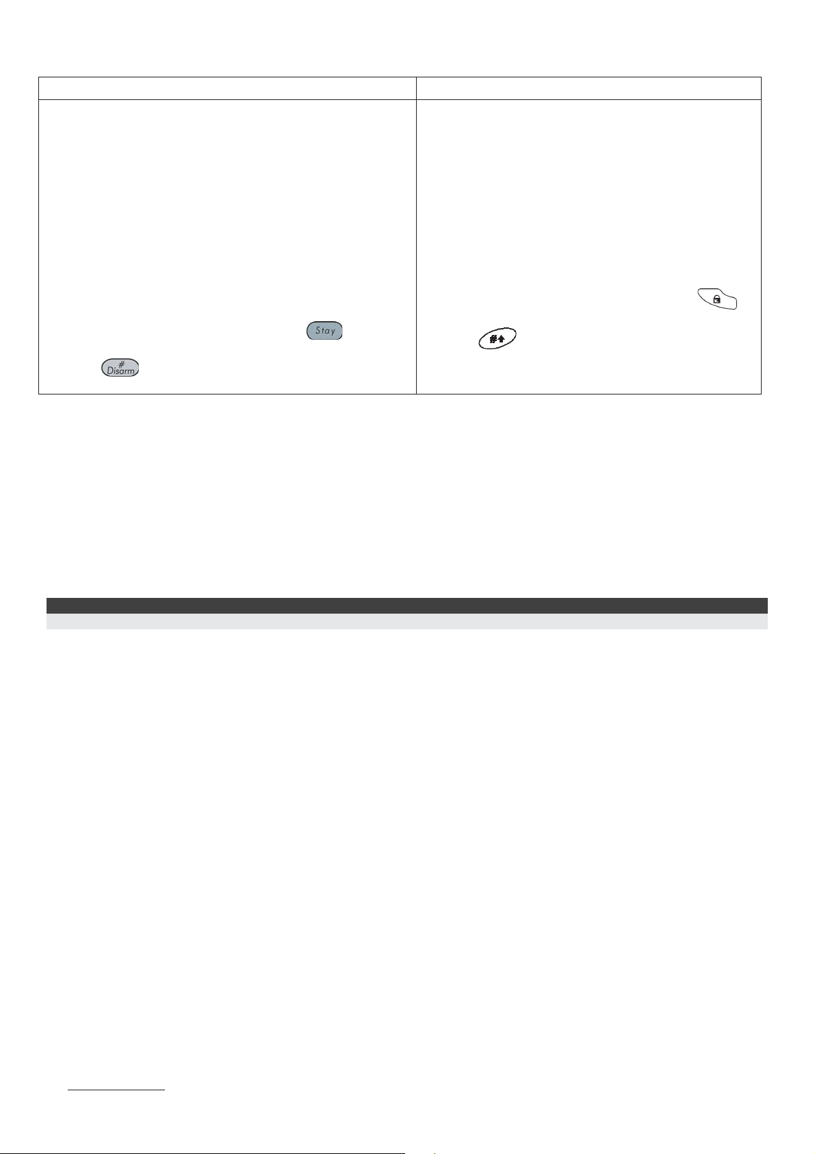
7. Select the UO type as “XO08” using the
key to
toggle between the options.
8. Press
to store the choice and to repeat the
process for any other utility output.
1. Set the ID DIP switches to the OFF position.
2. Enter the Installer menu
3. Press [9] for “More Devices” menu.
4. Press [3] for X-10.
5. Press [1] for the Add/Del X-10 menu
6. Place the cursor over the X-10 ID field.
If J2 is positioned on 1 PIN:
Select ID 1. Utility outputs 5-12 will be added to the
system outputs.
If J2 is positioned on 2 PINs :
ID1 for utility outputs 5-12
ID2 for utility outputs 13-20
7. Place the cursor on the type field. Use the
key to select the X-10 as "XO08"
8. Press
to store the choice.
Communication Test
After allocating the X-10 it performs a communication test between the module and the security panel. The quality of the
communication is displayed in percentages. A result of less than 100% means that there is a BUS connection problem
(for example bad wiring or cabling located in harsh electrical environment).
ProSYS: Installer programming menu, Quick key [7][3]
WisDom: Installer programming menu [9][3][2]
Defining X-10 Output Parameters
The definition and operation of the X-10 outputs is identical to the outputs in the security system.
Note
In the WisDom only outputs 5-20 are used for X-10.
USA
Tel:+305-592-3820
ssaalleess--uussaa@@rriissccooggrroouupp..ccoom
ssuuppppoorrtt--uussaa@@rriissccooggrroouupp..ccoom
wwwwww..rriissccooggrroouupp..ccoom
© RISCO Group
m
m
UK
Tel: +44-161-655-5500
sales@riscogroup.co.uk
m
technical@riscogroup.co.uk
ITALY
Tel: +39-02-66590054
info@riscogroup.it
support@riscogroup.it
SPAIN
Tel: +34-91-490-2133
sales-es@riscogroup.com
support-es@riscogroup.com
BRAZIL
Tel: +55-11-3661-8767
sales-br@riscogroup.com
support-br@riscogroup.com
ISRAEL
Tel: +972-3963-7777
iinnffoo@@rriissccooggrroouupp..ccoom
ssuuppppoorrtt@@rriissccooggrro
2/14 5IN128X10 B
m
o
uupp..ccoom
m
 Loading...