


Brivis StarPro SP615UN
Rinnai Brivis StarPro SP615UN, Brivis StarPro SP615IN, Brivis StarPro Series, Brivis StarPro SP635UN, Brivis StarPro SP630UN XA Installation Manual
...
Brivis StarPro
by
Ducted Gas Heater
Installation Manual
SP623 UN
BX5
PLEASE READ THESE INSTRUCTIONS CAREFULLY
BEFORE INSTALLING THIS PRODUCT
SP521IN

This page is intentionally blank
Rinnai 2 Ducted Gas Heater IM

Table of Contents
Warnings and Important Information 5
1. Scope 7
1.1 SP Heater Overview......................................................................................................................................... 7
1.2 BX5 Heater Overview....................................................................................................................................... 7
1.3 Installer Due Diligence for Changeovers ......................................................................................................... 8
Definitions ................................................................................................................................................................... 8
Disclaimer ................................................................................................................................................................... 8
2. General Product Guidelines 9
2.1 Application and Sizing ...................................................................................................................................... 9
2.2 Inspection ......................................................................................................................................................... 9
2.3 Unpacking the Heater ...................................................................................................................................... 9
2.4 Unloading or Lifting the Heater ........................................................................................................................ 9
2.5 Service Connection Guidelines ...................................................................................................................... 10
2.5.1 Gas Inlet Connection ......................................................................................................................... 10
2.5.2 Electrical Power Supply ..................................................................................................................... 10
3. Heater Dimensions and Clearances 11
3.1 Heater Dimensions – SP4, SP5 and SP6 ...................................................................................................... 11
3.2 Heater Dimensions – BX5 .............................................................................................................................. 12
3.3 Service Clearances – Internal ........................................................................................................................ 13
3.3.1 Service Clearance Notes ................................................................................................................... 13
3.3.2 Internal Clearances ............................................................................................................................ 13
3.4 Service Clearances – External ....................................................................................................................... 14
3.4.1 Installation of Flashing ....................................................................................................................... 14
3.4.2 SP4, SP5 and SP6 External Clearances ........................................................................................... 14
3.4.3 BX5 Service Clearances .................................................................................................................... 15
4. Heater Configuration 16
4.1 Heater Duct Pop Installation .......................................................................................................................... 16
4.2 Duct Connection Configuration Options ......................................................................................................... 16
Return Air Orientation............................................................................................................................................... 17
4.2.1 SP430U and SP435U Fan Cabinet: Swap F1 – F2 .......................................................................... 17
4.2.2 SP415U, SP421U Fan Cabinet: Swap F1/F2 – F3 ........................................................................... 17
4.2.3 SP5U and SP6U Fan Cabinet: Swap F1 – F2 .................................................................................. 17
4.2.4 SP5U and SP6U Fan Cabinet: Swap F1/F2 – F3 ............................................................................. 17
4.2.5 SP5 and SP6 Internal Fan Cabinet: Swap F1 – F2/F3 ..................................................................... 17
Supply Air Orientation .............................................................................................................................................. 18
4.2.6 SP4 Heater Cabinet: Swap H1/H2 – H3 ............................................................................................ 18
4.2.7 SP5 and SP6 Heater Cabinet: Swap Any Combination of H1, H2 or H3 .......................................... 18
Supply Air Switch Position – SP623U/630U/521U ................................................................................................... 18
4.2.8 Supply Air Switch Position ................................................................................................................. 18
4.3 SP Series Gas Feed Tube Installation ........................................................................................................... 19
5. Condensate Removal 20
5.1 Condensate Drain .......................................................................................................................................... 20
5.1.1 Install a Condensate Drain to an SP6 Universal and Internal Units .................................................. 20
6. Heater Positioning 21
6.1 Wall Cut-out Area ........................................................................................................................................... 21
6.2 Splitting Heater for Assisted Lifting and Positioning ...................................................................................... 21
6.2.1 SP4 Universal Heater ........................................................................................................................ 21
6.2.2 SP5 Universal Heater ........................................................................................................................ 22
6.2.3 SP5 and SP6 Internal Heater ............................................................................................................ 22
6.2.4 SP6 Universal Heater ........................................................................................................................ 22
Rinnai 3 Ducted Gas Heater IM

6.3 Internal Installations ....................................................................................................................................... 23
6.3.1 Installation in the Roof Space ............................................................................................................ 23
6.3.2 Installation Beneath the Floor ............................................................................................................ 23
6.3.3 Ventilation Calculations ...................................................................................................................... 23
6.4 External Installations ...................................................................................................................................... 24
6.4.1 SP4 – Installation of Flashing ............................................................................................................ 25
6.4.2 SP5 and SP6 – Installation of Flashing ............................................................................................ 25
7. Flue Instructions and Clearances 26
7.1 Internal – SP Series ....................................................................................................................................... 26
7.1.1 General .............................................................................................................................................. 26
7.1.2 SP4 and SP5 Models – 100mm Non-corrosive Metal Flue. .............................................................. 26
7.1.3 SP6 Universal Models – 100mm Drainage Waste Vent (DWV) Flue ................................................ 26
7.1.4 Remote Terminal (Part No. B018384) Internal Model Applications ................................................... 27
7.2 External – SP Series Flue Terminal Clearances ........................................................................................... 28
7.2.1 Installation of Flue Terminal ............................................................................................................... 28
7.3 External – BX5 Flue Terminal Clearances ..................................................................................................... 29
8. Thermistor Installation 30
8.1 SP Series Thermistor Installation ................................................................................................................... 30
8.2 BX5 Thermistor Installation ............................................................................................................................ 30
9. Ducting and Outlets 32
9.2 Return Air Grille.............................................................................................................................................. 32
9.3 Return Air Pop Configuration Changes ......................................................................................................... 32
9.4 Outlet Chart Information ................................................................................................................................. 33
10. Thermostat Installation 35
10.1 SP and BX5 Series Thermostat Positioning Guidelines ................................................................................ 35
10.2 Programmable and Manual Thermostat Installation ...................................................................................... 35
10.2.1 Connect a Programmable Thermostat ............................................................................................... 35
10.2.2 Connect a Manual Thermostat .......................................................................................................... 36
11. Networker Installation: Single and Multiple Connections 38
11.1 Networker Installation ..................................................................................................................................... 38
11.2 Connect a Networker to SP or BX5 Series Heaters ...................................................................................... 38
11.3 Connect a Networker to a BX5 Heater .......................................................................................................... 38
11.3.1 Connect Multiple Heaters to a Networker .......................................................................................... 39
11.3.2 Connect Dual Networkers .................................................................................................................. 39
11.3.3 Change a Networker from Slave to Master ....................................................................................... 40
11.3.4 Network 516 Manual .......................................................................................................................... 40
11.3.5 ZonePlus ............................................................................................................................................ 40
12. Adaptive Zoning and Add-on Air Conditioning 41
12.1 Options ........................................................................................................................................................... 41
12.2 Damper Motor Connections ........................................................................................................................... 41
12.3 Connect a Damper Motor to the Control Module ........................................................................................... 42
13. Commissioning and Control Settings 43
13.1 SP4, SP5, SP6 and BX5 Heater Control Settings ......................................................................................... 43
13.2 SP4, SP5, SP6 and BX5 Commissioning Instructions .................................................................................. 45
13.2.1 Initial Damper Settings ....................................................................................................................... 45
13.2.2 Initial Ignition and Gas Inlet Pressure Check .................................................................................... 45
13.2.3 Heater Temperature Settings and Fan Speed ................................................................................... 45
13.3 Final Checks (SP4, SP5, SP6 and BX5 Heaters) .......................................................................................... 47
13.4 Fault Code Identification on Heater PCB ....................................................................................................... 47
14. Technical Specifications 49
Rinnai 4 Ducted Gas Heater IM
WARNING
WARNING
NOTE
WARNINGS AND IMPORTANT INFORMATION
READ ALL INSTRUCTIONS BEFORE USING THE APPLIANCE.
Always comply with the following precautions to avoid dangerous situations and to ensure
optimum performance.
Failure to carefully read and follow all instructions in this manual can result in equipment
malfunction, property damage, personal injury and/or death.
DANGER: Indicates an imminently hazardous situation which, if not avoided, will result in
personal injury or death.
WARNINGS: Indicates a potentially hazardous situation which, if not avoided, could result in
personal injury or death.
CAUTIONS: Indicates a potentially hazardous situation which, if not avoided, could result in
minor or moderate injury or damage to the appliance. It may also be used to alert against unsafe
practices.
REGULATORY / INSTALLATION
This appliance shall be installed in accordance with:
• Manufacturer’s Installation Instructions.
• Current AS/NZS 5601, AS/NZS 5141 and AS/NZ 3000.
• AS 4254 - Ductwork for air-handling systems in buildings.
• HB 276-2004 – A Guide to Good Practice.
• Local Gas and Electricity Authorities.
• “SuperSizeGuide”
• Building Code of Australia (BCA) including local OH&S requirements
• Environment Authorities
This appliance must be installed, maintained and removed by an Authorised Person.
For continued safety of this appliance it must be installed and maintained in accordance with the
manufacturers instructions.
This appliance is heavy, use 2 people or mechanical lifting device. Improper lifting may result in
serious injury.
Take care when opening or unpacking this appliance. Failure to do so may result in serious injury
or product failure.
DO NOT modify the electrical wiring of this appliance. If the control power wiring is damaged
or deteriorated then it must be replaced by an authorised person. Failure to do so may result in
electric shock, re, serious injury or product failure.
DO NOT install the heater on an unstable or non level surface or where there may be a danger
of it falling. It may result in death, serious injury, or product failure.
DO NOT install the outdoor unit where noise may cause nuisance.
A NOTE ON ILLUSTRATIONS
The illustrations used in this manual are for explanatory purposes only and the shape of your unit
may vary slightly from that which is shown in this manual.
Rinnai 5 Ducted Gas Heater IM

NOTE
The manufacturer cannot guarantee compatibility and support for anyone using 3rd party
accessory/devices (device) on any of their appliances.
The suitability, compatibility or functional performance of any 3rd party device is entirely the
responsibility of the device’s supplier or installer.
Any 3rd party device, technical, installation, operation, performance or other enquiries need to be
referred to the device’s supplier or installer.
Any adverse eects of 3rd party devices on the operation, performance or reliability of this
appliance is not covered by the manufacturer’s product warranty.
Rinnai 6 Ducted Gas Heater IM
1. SCOPE
This installation manual is intended to be used as a guideline for the installation of Gas Fired Central Heaters.
It covers only the installation and commissioning of the heater and the allowable ueing congurations. Although
recommended return air grilles and allowable duct outlet quantities are specied, it does not cover the actual ducting
design required to suit the installation.
This installation manual is based on Australian codes. For all other applications, please refer to local codes and
regulations.
These heaters must be installed and serviced only by qualied personnel. This manual applies to the following
models:
6 Series Heaters 5 Series Heaters 4 Series Heaters
Universal Internal Universal External Internal Universal
SP615UN SP615IN SP521UN BX520EN SP521IN SP415UN
SP623UN SP623IN SP521UN XA SP521IN-XA SP421UN
SP623UN XA SP623IN XA SP530UN BX526EN SP530IN SP430UN
SP630UN SP630IN SP530UN XA SP530IN-XA SP435UN
SP630UN XA SP630IN XA SP535UN SP535IN
SP635UN SP635IN
1.1 SP Heater Overview
SP6 series heaters are condensing heaters.
SP4 and SP5 series heaters are non-condensing heaters.
Universal models may be used in both internal and external applications.
For more details refer to Technical Specications section.
1.2 BX5 Heater Overview
The BX520 and BX526 ducted heaters are designed primarily to replace Bualo 85 and Bualo 120 heaters
respectively. Their conguration allows for seamless changeover onto an existing base box, where applicable, with
identical service connections, capacities and airows commensurate with the original units. They also incorporate
on-board controls providing greater exibility for thermostat and zone control options.
Rinnai 7 Ducted Gas Heater IM

1.3 Installer Due Diligence for Changeovers
Modern ducted gas heaters, even those that are physically ‘like-for-like’, typically have dierent technical specications
and control systems to existing, older models. Modern units usually have higher Star Ratings, which are accompanied
by higher airows. Higher eciency heaters with modulating gas valves also operate dierently to non-modulating
units.
When doing a direct unit change over:
Do a comprehensive inspection of the entire existing system to ensure it is ‘t for purpose’ with the new heater
•
Check existing items that are not being replaced; i.e. ensure the soundness and suitability of all ttings and
•
controls for use with the new ducted gas heater (e.g. Duct sizes, Flue, Return Air grille size, Thermostat, Zoning
etc.)
Correctly commission the new ducted gas heater – where possible, align it with the performance characteristics
•
of the original system – do not leave units at the factory default settings unless you are absolutely certain the
settings are appropriate
Failure to observe best practice can lead to costly call backs for installers, unnecessary manufacturer warranty calls
and a poor customer experience.
With our policy of continuous improvement, we reserve the right to change, or discontinue at any time, specications
or designs without notice.
Definitions
Shall
Indicates a mandatory requirement of this manual.
Should
Indicates a recommended requirement of this manual.
Any deviations from these instructions may, at the discretion of the manufacturer, void the warranty. As a result, the
customer and/or installer may be charged a fee for non-product warranty related call outs. Also note that failure to
comply with these instructions may preclude company service personnel from being able to service the unit.
Disclaimer
IMPORTANT: This document is a guide only. Laws, regulations and industry standards can vary between States and Territories.
Accordingly, this guide must be read in conjunction with, and subject to, all laws, regulations and industry standards
applicable in the State or Territory in which the products are installed. You must ensure that the installation of the
products will comply with those laws, regulations and standards, and that the products recommended to customers
are fit for the purpose for which they are intended.
Rinnai 8 Ducted Gas Heater IM

2. GENERAL PRODUCT GUIDELINES
2.1 APPLICATION AND SIZING
These heaters are designed to provide a central source of heat for a ducted central heating system.
The heaters should not be installed downstream from an air washer, an evaporative cooler or refrigerative cooling
system. Nor are they designed to be installed on a marine craft, houseboat, or any similar environment.
The heaters must be installed in accordance with these instructions and related regulations, codes, standards, and
authorities. These include but may not be limited to:
• AS/NZS 3000 - Electrical Installations
• AS/NZS 5601 - Gas Installations
• AS 4254 - Ductwork for air-handling systems in buildings
• HB 276 - A Guide to Good Practice
• AS/NZS 5141 - Residential Climate Control Systems
• Local Gas and Electricity Authority Codes
Note: The manufacturer assumes no responsibility for equipment installed in violation of any code, regulations and these installation
instructions..
It is recommended the Product Sizing Guide is followed in estimating heating requirements and for system design
that will result in efficient installation and provide a higher level of comfort and economical operation.
For the hourly input and the gas type to be used, refer to the appliance data label located inside the service
compartment or the Technical Specifications at the rear of this manual.
Note: All installations should only be carried out by a qualified tradesperson. Installations at altitudes above 1000m above sea level
may require main burner injector upgrading. Please contact the Customer Service Centre for advice.
• Product Sizing Guide
• Local Building Regulations
• Environment Authorities
• National Construction Code of Australia (NCC)
2.2 INSPECTION
This appliance has been inspected and tested at the time of manufacture and packaging and released for
transportation without known damage. Upon receipt, inspect the exterior for evidence of rough handling in shipment.
Ensure that the appliance is labelled correctly for the gas to which it is intended to be connected. If a discrepancy or
damage to the appliance is identified DO NOT install the appliance and report findings back to supplier.
2.3 UNPACKING THE HEATER
Some heaters are supplied on a pallet with a plastic sleeve. To unpack:
Cut and remove the external plastic packaging and dispose of thoughtfully.
Remove heater from pallet (if supplied).
Some heaters are supplied with a base box assembly wrapped with a removable plastic film to protect the surface.
Note: Always remove and dispose of the plastic film before mounting the heater onto the base box.
2.4 UNLOADING OR LIFTING THE HEATER
When unloading or lifting the heater, ensure lifting equipment is in good operating condition and capable of lifting
the total load. Be sure there is a clear area to place the heater down, which is within reach of the lifting equipment.
Note: Do not use the lifting handles provided to lift the heater above head height. If fitting the heater to elevated heights such as a
roof, use suitable lifting equipment.
Rinnai 9 Ducted Gas Heater IM

2.5 SERVICE CONNECTION GUIDELINES
2.5.1 Gas Inlet Connection
• All piping must be in accordance with AS/NZS 5601 and any local gas regulations.
• The connection point for universal and external model heaters is a female G3/4 compression fitting to AS 3688.
This is either located on the outer cabinet of the heater, or supplied loose within the heater.
• The connection point for internal model heaters is a male G3/4 compression fitting to AS 3688.
• A gas cock shall be fitted in the gas line adjacent to the heater and in a convenient location so it can be turned
OFF quickly and easily.
• The gas supply shall in no way interfere with any servicing of the heater.
Note: The gas supply must be installed by a licensed gas fitter. The gas pipe and gas meter should be sized so the heater can
maintain its required incoming gas pressure at maximum consumption with all other gas appliances operating at their maximum
capacity at the same time as the heater.
2.5.2 Electrical Power Supply
The heater is pre-wired with a 3-pin plug and lead, and shall be plugged into a standard 10 Amp 220-240V fixed
switched socket outlet adjacent to the heater in a convenient location so it can be turned OFF quickly and easily.
Note: A qualified electrician must install the 220 to 240 volt wiring according to local regulations.
IMPORTANT: Switch OFF the power and unplug the heater before touching any wiring. If any electrical wiring is damaged, it must
be replaced by the manufacturer, its service agents or an electrically qualified technician, in order to avoid a hazard.
The electricity supply must be 220-240V at 50Hz, and supplied by an authorised power supplier. Generators should
never be used to supply this system as their output may be incompatible with, or prone to damage electronic
components of the heater.
Rinnai 10 Ducted Gas Heater IM
3. HEATER DIMENSIONS AND CLEARANCES
3.1 HEATER DIMENSIONS – SP4, SP5 AND SP6
Diagram 1. SP4, SP5 and SP6 Universal Heater Dimensions (SP6U illustrated)
M
L
POWER LEAD
FLUE OUTLET
ØRa
H
G
K
J
N
GAS INLET
B
ØSa
E
F
D
C
Table 1. SP4, SP5 and SP6 Universal Heater Dimensions (mm)
UNIVERSAL
MODEL
SP415UN 14 397 197 235 625 467 448 845 197 235 95 495 447 300 300
SP421UN 14 397 197 235 625 467 448 845 197 235 95 495 447 300 300
A B C D E F G H J K L M N øSa øRa
A
SP430UN 14 549 197 235 644 487 497 923 237 235 250 515 487 350 350
SP435UN 14 549 197 235 644 487 497 923 237 235 250 515 487 400 400
SP521UN-XA 14 428 214 222 658 478 419 991 209 222 110 517 574 350 350
SP521UN 14 428 214 222 658 478 419 991 209 222 110 517 574 300 300
SP530UN-XA 14 550 275 222 707 526 419 1083 209 222 250 565 574 400 400
SP530UN 14 550 275 247 707 526 539 1083 270 247 250 565 539 350 350
SP535UN 14 550 275 247 707 526 539 1083 270 247 250 565 539 450 450
SP615UN 14 428 214 222 658 478 419 991 209 222 110 517 574 300 300
SP623UN-XA 14 428 214 222 658 478 419 991 209 222 110 517 574 350 350
SP623UN 14 428 214 222 658 478 419 991 209 222 110 517 574 300 300
SP630UN-XA 14 550 275 247 707 526 539 1083 270 247 250 565 539 400 400
SP630UN 14 550 275 247 707 526 539 1083 270 247 250 565 539 350 350
SP635UN 14 550 275 247 707 526 539 1083 270 247 250 565 539 450 450
Note: SP4, SP5 and SP6 Universal models are approved for internal or external applications.
Rinnai 11 Ducted Gas Heater IM
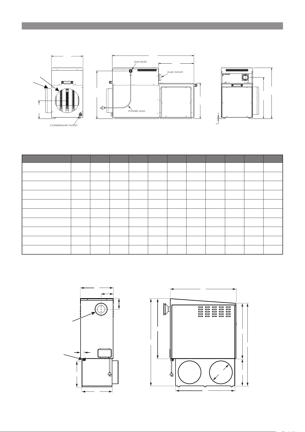
Diagram 2. SP5/6 Internal Heater Dimensions
N
H
C
SP6 & SP5 Internal
A
C
øSa
øRa
D
J
(SP6 MODELS ONLY)
B
E
H
F
G
Table 2. SP5/6 Internal Heater Dimensions (mm)
INTERNAL MODEL A B C D E F G H J øSa øRa
SP521IN 634 1021 395 594 440 440 15 513 224 300 300
SP521IN-XA 634 1021 395 594 440 440 15 513 224 350 350
SP530IN 684 1070 547 643 491 490 15 563 253 350 350
SP530IN-XA 684 1070 547 643 491 490 15 563 253 400 400
SP535IN 684 1070 547 643 491 490 15 563 253 450 450
SP615IN 634 1021 395 594 440 440 15 513 224 300 300
SP623IN 634 1021 395 594 440 440 15 513 224 350 350
SP623IN-XA 684 1070 547 643 491 490 15 563 253 350 350
SP630IN 684 1070 547 643 491 490 15 563 253 400 400
SP630IN-XA 684 1070 547 643 491 490 15 563 253 450 450
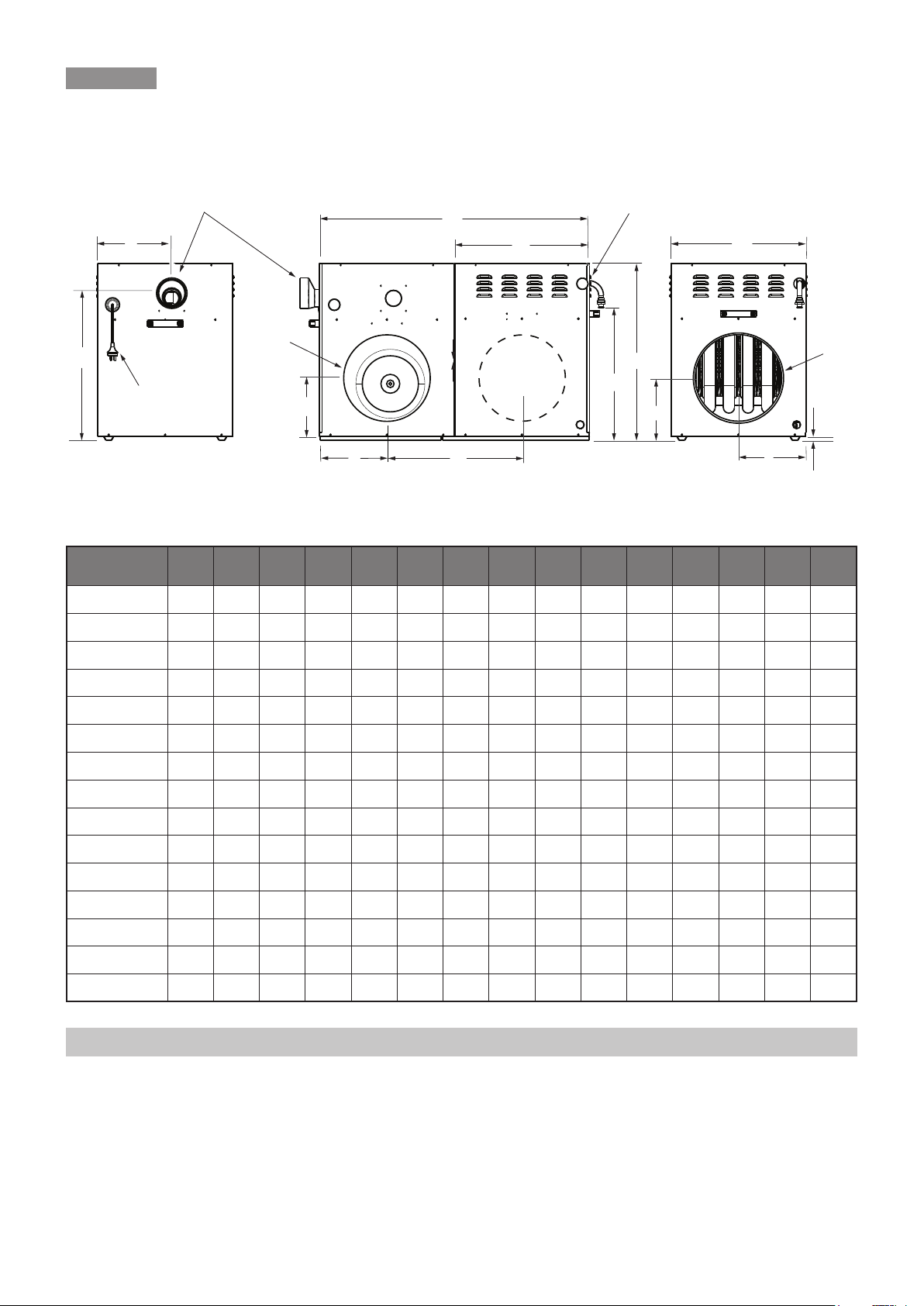
3.2 HEATER DIMENSIONS – BX5
Diagram 3. BX5 Heater Dimensions
TERMINAL
INLET
GAS
FLUE
F
G
A
J
E
B
K
L
D
Ø P
M
Rinnai 12 Ducted Gas Heater IM
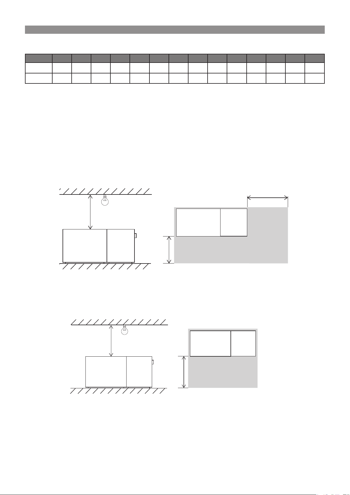
Table 3. BX5 Heater Dimensions (mm)
Side View Plan View
MODEL A B C D E F G H J K L M N P
BX520 775 852 420 341 41 156 135 391 1145 715 1085 370 771 300
BX526 866 1028 582 387 41 238 135 557 1280 805 1220 415 951 350
3.3 SERVICE CLEARANCES – INTERNAL
3.3.1 Service Clearance Notes
All SP6 models, SP5 models, SP415 and SP421 models can be installed in accordance with 'Method 1',
'Method 2', 'Method 3' and 'Method 4' below. The SP430 and SP435 can be installed in accordance with 'Method 1'
and 'Method 2' only.
3.3.2 Internal Clearances
Method 1: In Ceiling and Under Floor
Diagram 4. Method 1 Clearances
750mm
Minimum
250 mm
Minimum
Heat
Exchanger
Cabinet
Fan Cabinet
Heat
Exchanger
Cabinet
Fan
Cabinet
Side View Plan View
Method 2: In Ceiling and Under Floor
Diagram 5. Method 2 Clearances
800 mm
Minimum
Heat
Exchanger
Cabinet
Fan
Cabinet
750mm
Minimum
750mm
Minimum
Service Clearance
Heat
Exchanger
Cabinet
Service Clearance
Platform
Fan Cabinet
Platform
Rinnai 13 Ducted Gas Heater IM

Method 3: Lay-down Option – In Ceiling
Diagram 6. Method 3 Clearances
700 mm
Service
Clearance
(Full length of heater)
300 mm (refer to AS5601)
750 mm
Method 4: Lay-down Option – Under Floor
Diagram 7. Method Clearances
700 mm
Service
Clearance
(Full length of heater)
750 mm
200 mm (
Side View
refer to AS5601)
Concrete Base 50mm
Side View
Fire resistant board
(refer to AS5601)
Lowest part of floor structure
Ground
Note: Method 3 and Method 4 are not options for SP430 and SP435 models. These models may be installed to Method 1 or Method
2 only.
3.4 SERVICE CLEARANCES – EXTERNAL
3.4.1 Installation of Flashing
The flashing must be fitted to ensure the ductwork is adequately weather protected.
Note: To allow the heater to be moved out from the wall such as for servicing, it is important to provide additional length in the ducting
connected to the pops.
3.4.2 SP4, SP5 and SP6 External Clearances
Front: A minimum of 500mm must be provided at the side facing away from the house.
End: A minimum of 300mm must be provided at each end of the heater.
Top: A minimum of 1000mm must be provided above the heater roof. This clearance must be maintained for the
entire surface area of the heater roof.
Rinnai 14 Ducted Gas Heater IM

Diagram 8. External Clearances
Plan View
1000 mm min
Service
Clearance
(Top)
Side View
500 mm min
(Front)
Service Clearance
Flashing
Service
Clearance
(Front)
300 mm
min
300 mm
min
(End)(End)
500 mm
min
3.4.3 BX5 Service Clearances
Front: A minimum of 500mm must be provided at the side facing away from the house.
End: A minimum of 300mm must be provided at each end of the heater.
Top: A minimum of 1000mm must be provided above the heater roof. This clearance must be maintained for the
entire surface area of the heater roof.
Diagram 9. BX5 Clearances
Plan View
1000 mm min
Service
Clearance
(Top)
Side View
500 mm min
(Front)
300 mm
min
(End) (End)
Service Clearance
300 mm
min
Service
Clearance
(Front)
500 mm
min
Flashing
Rinnai 15 Ducted Gas Heater IM

4. HEATER CONFIGURATION
4.1 HEATER DUCT POP INSTALLATION
On all SP series heaters, the duct connection pops need to be fastened to the heater cabinet as follows:
• Insert pops into the hole in the pop plate, ensuring the pop flange is placed over the prescribed wall of the
cabinet, refer to Table 4.
• Spread pop flange to fit tightly into the hole in the cabinet (the notch side overlapping the other).
• Secure pops with the rivets supplied.
Table 4. Pop Installation
Matrix
Universal Model Cabinet
Internal Model Cabinet
No. of Walls Install Pop No. of Walls Install Pop
SP4 2 Inner Wall 2 Inner Wall
SP5 1 No Option 2 Inner Wall
SP6 1 No Option 2 Inner Wall
SP5 1 No Option 2 Inner Wall
SP6 1 No Option 2 Inner Wall
Return Air Supply Air
4.2 DUCT CONNECTION CONFIGURATION OPTIONS
(Not applicable BX5 Models)
For SP Series heaters, the return air and supply air duct connections can be reconfigured. That is, the heater panels
can be repositioned to move the duct outlet/inlet to the back or to the side of the unit to suit the specific installation.
Change Duct Connection Locations
Simplistically, the heater unit is made up of two cabinets: a heater cabinet (air heating components) and a fan
cabinet, (supply air fan). Diagram 10 identifies three pop positions on the heater cabinet (H1, H2 and H3) and three
pop positions on the fan cabinet (F1, F2 and F3).
Diagram 10. Duct Connection Options
Return Pop Position
from Factory
H1
HEATER CABINET FAN CABINET
F1
SUPPLY AIR
SIDE
Supply Pop
H3 F3
Position
from
Factory
H2
RETURN AIR
SIDE
F2
SP430U and SP435U: The pops can be configured to support any combination of the following options:
• Return air pop: Can be positioned at F1 or F2 (Diagram 10).
• Supply air pop: Can be positioned at H1, H2 or H3.
SP415U, SP421U, SP5U and SP6U: The pops can be configured to support any combination of the following
options:
• Return air pop: Can be positioned at F1, F2 or F3 (Diagram 10).
• Supply air pop: Can be positioned at H1, H2 or H3.
SP5 and SP6 Internal: The return air pop can be configured to support any combination of the following options:
• Return air pop: Can be positioned at F1 or F2 or F3 (Diagram 10).
• Supply air pop: Can be positioned at H3 only.
Rinnai 16 Ducted Gas Heater IM
 Loading...