


Direct Vent Wall Furnace
 Installation and Operation Manual
EX17CT...............(RHFE-434FTA2)
EX22CT...............(RHFE-559FTA2)
Installer: Leave this manual with the appliance.
Consumer: Retain this manual for future reference.
READ ALL OF THE INSTRUCTIONS THOROUGHLY BEFORE INSTALLING OR OPERATING THIS HEATER.
This manual provides information on the installation, operation, and maintenance of the heater. For proper operation and safety, it is important to follow the instructions and adhere to the safety precautions.
A licensed professional must install the fan convection heater according to the exact instructions within this manual.
The consumer must read the entire manual to properly operate the heater and to have regular maintenance performed.

 WARNING If the information in these instructions is not followed exactly, a fire or explosion may result causing property damage, personal injury or death.
—Do not store or use gasoline or other flammable vapors and liquids in the vicinity of this or any other appliance.
—WHAT TO DO IF YOU SMELL GAS
Do not try to light any appliance.
Do not touch any electrical switch; do not use any phone in your building.
Immediately call your gas supplier from a neighbor’s phone. Follow the gas supplier’s instructions.
If you cannot reach your gas supplier, call the fire department.
—Installation and service must be performed by a licensed professional.
Register your product at www.rinnairegistration.com or call 1-866-RINNAI1 (746-6241)
Table of Contents
Table of Contents............................................. |
2 |
Safety Definitions ............................................. |
2 |
Safety Behaviors and Practices for the Consumer |
|
and Installer...................................................... |
3 |
Installation Instructions |
|
(for the licensed professional) |
|
State Regulations ............................................. |
4 |
Included Installation and Vent Components .... |
5 |
Installation Instructions..................................... |
6 |
Prepare for Installation ..................................... |
7 |
Determine Installation Location........................ |
7 |
Flue Terminal Clearances ................................ |
8 |
Clearances to Combustibles ............................ |
9 |
Checklist to Determine Installation Location .... |
9 |
Drilling Flue Hole............................................ |
10 |
Flue Manifold Installation ............................... |
10 |
Extension Kit Installation ................................ |
12 |
Connecting the Appliance .............................. |
15 |
Gas Connection ............................................. |
16 |
Adjust Gas Pressure Settings ........................ |
16 |
Dimensions .................................................... |
20 |
Specifications ................................................. |
21 |
Direct Vent Furnace Operation Instructions |
|
Safe Operation .............................................. |
23 |
Getting to Know Your Appliance .................... |
24 |
Control Panel ................................................. |
25 |
ON / OFF........................................................ |
25 |
Child Lock ...................................................... |
25 |
Remote Thermostat Mode |
|
(Optional Accessory) ..................................... |
26 |
Setting the Clock............................................ |
27 |
Setting and Operating the Timers.................. |
27 |
Override Function .......................................... |
27 |
Economy (Energy Saving Mode) ................... |
28 |
Set Back......................................................... |
28 |
Humidifier and Air Flow Direction .................. |
29 |
Required Care and Maintenance |
|
Care and Maintenance .................................. |
30 |
Before Making a Service Call ........................ |
31 |
Diagnostic Codes and Remedies .................. |
32 |
Restart Function............................................. |
33 |
Troubleshooting ............................................. |
33 |
Cut-Away Diagram......................................... |
34 |
Wiring Diagram .............................................. |
35 |
Ladder Diagram ............................................. |
36 |
Parts List ........................................................ |
37 |
Warranty |
|
Warranty ........................................................ |
47 |
French Version............................................... |
49 |
NOTICE: Rinnai sometimes shares customer contact information with businesses that we believe provide products or services that may be useful to you. By providing this information, you agree that we can share your contact information for this purpose. If you prefer not to have your information shared with these businesses, please contact customer service and ask not to have your information shared. We will however, continue to contact you with information relevant to the product(s) you registered and/or your account with us.
If you have any questions or feel that the manual is incomplete contact Rinnai at 1-800-621-9419.
Important Safety Information
Safety Definitions
This is the safety alert symbol. This symbol alerts you to potential hazards that can kill or hurt you and others.
 DANGER
 WARNING
CAUTION
2
Indicates an imminently hazardous situation which, if not avoided, will result in death or serious injury.
Indicates a potentially hazardous situation which, if not avoided, could result in death or serious injury.
Indicates a potentially hazardous situation which, if not avoided, could result in minor or moderate injury. It may also be used to alert against unsafe practices.
Rinnai Corporation EX17CT, EX22CT Manual

Safety Behaviors and Practices for the Consumer and Installer
 WARNING
Repairs should be performed by a qualified service technician.
Keep the area around the appliance clear and free from combustible materials, gasoline, and other flammable vapors and liquids.
Never store liquid propane containers indoors.
Do not use this appliance if any part has been under water. Immediately call a qualified service technician to inspect the appliance and to replace any part of the control system and any gas control which has been under water.
This appliance is equipped with a three-prong plug for your protection against shock hazard and should be plugged directly into a properly grounded threeprong receptacle. Do not cut or remove the ground prong from this plug.
Any alteration to the appliance or its controls can be dangerous.
Do not operate appliance with the panels removed, cracked or broken. Replacement of the panels should be done by a licensed or qualified service person.
 CAUTION
Do not block the warm air discharge. Do not allow anyone to sleep directly in front of the appliance.
Due to high temperatures, the appliance should be located out of traffic and away from furniture and draperies.
Children and adults should be alerted to the hazards of high surface temperature and should stay away to avoid burns or clothing ignition.
Young children should be carefully supervised when they are in the same room as the appliance.
Clothing or other flammable material should not be placed on or near the appliance.
Any safety screen or guard removed for servicing must be replaced prior to operating the appliance.
Do not insert items into the louvers.
Do not spray aerosols near the appliance while it is operating. Most aerosols contain butane gas which is flammable.
Do not unplug the appliance while it is operating or while the fans are on.
Do not use bare hands to touch the front louvers due to high temperatures which may cause burns.
Wear hand protection when touching the side back covers, front louver, and rear intake for the convection fan.
Prevent dust from accumulating on the power cord, side covers, and parts behind the appliance.
Do not sit on the heater.
Do not place containers of liquid on top of the heater. Water spillage can cause extensive damage to the appliance and may result in electric shock.
Rinnai Corporation EX17CT, EX22CT Manual |
3 |
Installation Instructions (for the licensed professional)
State Regulations
NOTICE BEFORE INSTALLATION
Rinnai direct-vent appliance must be installed by a state qualified or licensed contractor and a properly
trained Rinnai Installer. If you are not properly trained, you must not install this unit.
IMPORTANT: In the State of Massachusetts (248 CMR 4.00 & 5.00)
For all side wall horizontally vented gas fueled equipment installed in every dwelling, building or structure used in whole or in part for residential purposes, including those owned or operated by the Commonwealth and where the side wall exhaust vent termination is less than seven (7) feet above finished grade in the area of the venting, including but not limited to decks and porches, the following requirements shall be satisfied:
1.INSTALLATION OF CARBON MONOXIDE DETECTORS. At the time of installation of the side wall horizontal vented gas fueled equipment, the installing plumber or gasfitter shall observe that a hard wired carbon monoxide detector with an alarm and battery back-up is installed on the floor level where the gas equipment is to be installed. In addition, the installing plumber or gasfitter shall observe that a battery operated or hard wired carbon monoxide detector with an alarm is installed on each additional level of the dwelling, building or structure served by the side wall horizontal vented gas fueled equipment. It shall be the responsibility of the property owner to secure the services of qualified licensed professionals for the installation of hard wired carbon monoxide detectors
a.In the event that the side wall horizontally vented gas fueled equipment is installed in a crawl space or an attic, the hard wired carbon monoxide detector with alarm and battery back-up may be installed on the next adjacent floor level.
b.In the event that the requirements of this subdivision can not be met at the time of completion of installation, the owner shall have a period of thirty (30) days to comply with the above requirements; provided, however, that during said thirty (30) day period, a battery operated carbon monoxide detector with an alarm shall be installed.
2.APPROVED CARBON MONOXIDE DETECTORS. Each carbon monoxide detector as required in accordance with the above provisions shall comply with NFPA 720 and be ANSI/UL 2034 listed and IAS certified.
3.SIGNAGE. A metal or plastic identification plate shall be permanently mounted to the exterior of the building at a minimum height of eight (8) feet above grade directly in line with the exhaust vent terminal for the horizontally vented gas fueled heating appliance or equipment. The sign shall read, in print size no less than one-half (1/2) inch in size, "GAS VENT DIRECTLY BELOW. KEEP CLEAR OF ALL OBSTRUCTIONS".
4.INSPECTION. The state or local gas inspector of the side wall horizontally vented gas fueled equipment shall not approve the installation unless, upon inspection, the inspector observes carbon monoxide detectors and signage installed in accordance with the provisions of 248 CMR 5.08(2)(a)1 through 4.
4 |
Rinnai Corporation EX17CT, EX22CT Manual |

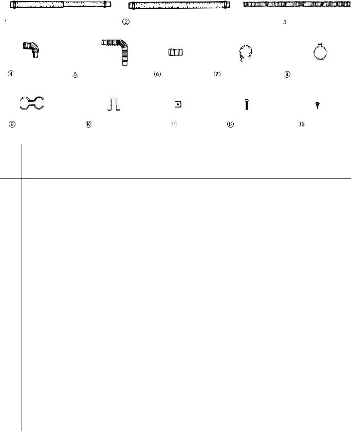
Included Installation and Venting Components
The following items are included with the appliance:
Flue Manifold  1 Spare rubber seal
  1
1
(‘A’ Flue units only)
“A” Vent Kit, FOT-151
(For weatherboard installations)
|
|
|
|
Pipe Stopper A |
|
|
|
|
|
|
|
|
Ring |
|
|
|
|
Back Spacer |
|
|
|
|
|
|
|
|
Set |
|
|
1 |
|
|
|
|
|
|
|
|
Manual Valve |
|
|
|
||
|
|
|
|
|
|
|
||
|
|
|
|
Set |
|
|
|
|
|
|
|
|
Plastic tie |
|
|
|
|
|
|
|
|
for air inlet |
|
|
|
|
|
Owner’s Manual |
|
Plastic tie* |
|
|
|
||
|
1 |
(L=250mm) |
|
|
|
|||
|
|
|
|
|
|
|
||
Screw |
|
|
|
Screw |
|
|
|
|
(M4) |
|
|
4 |
(M4) |
|
|
|
|
For Back Spacer Set |
|
|
For Flue Manifold |
|||||
|
|
|
|
|||||
Screw |
|
|
4 |
Wood Screw |
|
|
|
|
|
|
|
|
|
||||
(M4) |
|
|
(M4.8 |
32) |
|
|
|
|
For Spacer Bracket |
|
Wall Bracket Screws |
||||||
|
|
|
|
|||||
Wall Bracket |
|
|
1 |
Spacer Bracket |
|
|
|
|
|
|
|
|
|
||||
|
|
|
|
|
||||
* This plastic tie
Flue Manifolds should be located here
The following flue manifold sizes are available for different wall thicknesses:
|
|
|
|
|
|
|
|
|
|
|
|
|
|
|
(Vent A Kit is included |
|
|
|
|
|
|
|
|
|
|
|
|
|
|
|
|
||
|
|
|
|
|
|
|
|
|
|
|
|
|
|
|
with the appliance.) |
|
|
|
|
|
|
|
|
|
|
|
|
|
|
|
|
||
|
|
|
|
|
|
|
|
|
|
|
|
|
|
|
|
|
Name |
|
Kit No. |
|
|
|
|
fits walls |
|
||||||||
|
|
|
|
|
|
|
|
|
|
|
|
|
|
|
|
|
S Vent Kit |
|
FOT-150 |
|
|
3 - 4 1/2 in (75 - 115 mm) |
|
||||||||||
|
|
|
|
|
|
|
|
|
|
|
|
|
|
|
|
|
A Vent Kit |
|
FOT-151 |
4 |
1/2 - 9 1/2 in (115 - 240 mm) |
|
|||||||||||
|
|
|
|
|
|
|
|
|
|
|
|
|
|
|
|
|
B Vent Kit |
|
FOT-152 |
|
9 1/2 - 15 3/4 in (240 - 400mm) |
|
|||||||||||
|
|
|
|
|
|
|
|
|
|
|
|
|
|
|
|
|
C Vent Kit |
|
FOT-153 |
15 |
3/4 - 23 5/8 in (400 - 600 mm) |
|
|||||||||||
|
|
|
|
|
|
|
|
|
|
|
|
|
|
|
|
|
D Vent Kit |
|
FOT-154 |
23 |
5/8 - 31 1/2 in (600 - 800 mm) |
|
|||||||||||
|
|
|
|
|
|
|
|
|
|
|
|
|
|
|
|
|
Rinnai Corporation EX17CT, EX22CT Manual
1
1
1
1
1
3
5
1
5

Installation Instructions
Installer Qualifications
A licensed professional must install the appliance, inspect it, and leak test it before use. The warranty will be voided due to any improper installation.
The installer should have skills such as:
Gas sizing.
Connecting gas lines, valves, and electricity.
Knowledge of applicable national, state, and local codes.
Installing venting through a wall.
Training in installation of direct vent furnaces. (Training can be accessed on-line at www.trainingevents.rinnai.us)
Type of installation
For installation in residential and commercial applications.
Certified for installation in manufactured (mobile) homes.
This appliance may be installed as an OEM installation in a manufactured home (USA only) or mobile home and must be installed in accordance with the manufacturer’s instructions and the Manufactured Home construction and Safety Standard, Title 24 CFR, Part 3280, in the United States, or the Mobile Home Standard, CAN/CSA Z240 MH Series, in Canada.
This appliance may be installed in an aftermarket, permanently located, manufactured home (USA only) or mobile home, where not prohibited by local codes.
This appliance is only for use with the type of gas indicated on the rating plate. This appliance is not convertible for use with other gases, unless a certified kit is used.
NOTICE |
If installation is at a location above |
|
2001 ft (610 m), then follow the Adjust |
|
|
|
Gas Pressure Settings procedure. |
|
Appliance input ratings are based on |
|
sea level operation and need not be |
|
changed for operation up to 2000 ft |
|
(610 m) elevation. |
|
|
General Instructions
This appliance discharges a large volume of warm air next to the floor. Any particles in the air such as cigarette smoke could cause discoloration in nylon carpets containing dyes or vinyl surfaces.
Rinnai suggests that a dedicated electrical circuit with a 120VAC, 60 Hz, 10 amp power source be used.
A test plug is provided for testing of manifold differential pressure. It is located on the modulating gas valve.
MUST DO
If you move, check the gas type in your new area. The local gas authority will be able to advise on local regulations.
The installation must conform with local codes or, in the absence of local codes, with the National Fuel Gas Code, ANSI Z223.1/NFPA 54, or the Natural Gas and Propane Installation Code, CSA B149.1.
A manufactured home (USA only) or mobile home OEM installation must conform with the
Manufactured Home Construction and Safety Standard, Title 24 CFR, Part 3280, or, when such a standard is not applicable, the standard for
Manufactured Home Installations, ANSI Z225.1, or the standard for Gas Equipped Recreational Vehicles and Mobile Housing, CSA Z240.4.
The appliance, when installed, must be electrically grounded in accordance with local codes or, in the absence of local codes, with the National Electrical Code, ANSI/NFPA 70, or the Canadian Electrical Code, CSA C22.1.
The appliance and its appliance main gas valve must be disconnected from the gas supply piping system during any pressure testing of that system at test pressures in excess of 1/2 psi (3.5 kPa).
The appliance must be isolated from the gas supply piping system by closing its equipment shutoff valve during any pressure testing of the gas supply piping system at test pressures equal to or less than 1/2 psi (3.5 kPa).
If the flooring is carpet or other combustible material other than wood, then the appliance must be installed on a metal or wood panel extending the full width and depth of the appliance.
This appliance is only for use with the type of gas indicated on the rating plate. This appliance is not convertible for use with other gases unless a certified kit is used. If conversion of the unit is needed, conversions must be performed by a qualified service provider at the owner’s expense.
The appliance should be correctly sized for the space it is required to heat. It is recommended that an Industry standard BTU Heat Loss Calculation be conducted to determine the proper sizing.
Follow the installations instructions and those in Care and Maintenance for adequate combustion and ventilation air.
6 |
Rinnai Corporation EX17CT, EX22CT Manual |

DO NOT |
|
Determine Installation Location |
|
This appliance is not designed to built in. |
|||
You must ensure that clearances will be met and that |
|||
This appliance must not be connected to a chimney |
|||
the vent length will be within required limits. Consider |
|||
flue serving a separate solid-fuel burning appliance. |
the installation environment. Requirements for the |
||
The flow of combustion and ventilation air shall not |
gas line and electrical connection can be found in their |
||
be obstructed. |
respective installation sections of this manual. |
||
|
|||
|
|
|
Environment |
|
WARNING |
|
|
||
|
|
Air surrounding the venting, and vent termination(s) is |
||
|
|
|
||
Do not use substitute materials. |
used for combustion and must be free of any |
|||
Use only parts certified with the appliance. |
compounds that cause corrosion of internal |
|||
components. These include corrosive compounds |
||||
|
|
|
||
|
|
|
that are found in aerosol sprays, detergents, bleaches, |
|
Prepare for Installation |
||||
cleaning solvents, oil based paints/ varnishes, and |
||||
Tools needed |
|
refrigerants. |
||
|
The furnace, venting, and vent termination(s) should |
|||
|
|
|
||
Pipe wrenches (2) |
Safety glasses |
not be installed in any areas where the air may |
||
contain these corrosive compounds. If it is necessary |
||||
Adjustable pliers |
Level |
|||
for a furnace to be located in areas that may contain |
||||
Screwdrivers (2) |
|
|||
|
corrosive compounds, the following |
|||
Wire cutters |
|
instructions are strongly recommended. |
||
Gloves |
|
IMPORTANT CONSIDERATIONS FOR: |
||
Tools that might be needed |
DO NOT Install in areas where air for combustion |
|||
might be contaminated with chemicals. |
||||
Hammer drill with |
Torch set |
Before installation, consider where air has the |
||
concrete bits |
Copper tubing cutter |
ability to travel within the building to the furnace. |
||
Saw |
Steel pipe cutter |
Terminate the unit as far away as possible from |
||
Threading machine with |
|
any air inlet vents. Corrosive fumes may be |
||
heads and oiler |
|
released through these vents when air is not |
||
Core drill with diamond |
|
being brought in through them. |
||
head |
|
Chemicals that are corrosive in nature should not |
||
|
|
|
be stored or used near the furnace or vent |
|
Materials needed |
|
termination. |
||
|
|
|||
Soap or gas leak |
Teflon tape |
Damage and repair due to corrosive compounds in the |
||
air is not covered by warranty. |
||||
detector solution |
(recommended) or pipe |
|||
|
||||
Approved venting |
compound |
|
||
Materials that may be needed
Heat tape
Pipe insulation
Concrete wall anchors
Optional pipe cover
Optional temperature controller
2 conductor 22 AWG wire for controller
Single gang electrical box
Wire nuts
Rinnai Corporation EX17CT, EX22CT Manual |
7 |
Flue Terminal Clearances
TERMINATION
Clearanceinin
Ref..AAalso applies to applies to anticipated anticipated snow line snow line
SNOW
D
E
 B
B
L
F 
INSIDE
CORNERDETAIL
G
A
|
|
|
B |
|
|
B |
FIXED |
|
|
CLOSED |
|
|
|
|
|
|
|
|
OPERABLE |
C |
|
B |
|
FIXED |
|
J |
|
|
|
B |
|
|
CLOSED |
|
|
|
|
A |
|
|
|
|
|
|
OPERABLE |
|
|
B 
H
I |
M |
|
K 
|
|
|
|
|
|
|
|
|
|
X |
|
|
||
AIR SUPPLY INLET |
||||
|
|
|||
|
|
VENT TERMINAL |
||
V |
|
|||
|
AREA WHERE |
|||
|
|
|||
|
|
TERMINAL IS NOT |
||
|
|
PERMITTTED |
||
|
|
|
|
|
Ref |
Description |
Canadian Installations |
US Installations |
|
|
|
|
|
|
A |
Clearance above grade, veranda, porch, deck, or balcony |
12 inches (30 cm) |
12 inches (30 cm) |
|
|
|
|
|
|
B |
Clearance to window or door that may be opened |
12 inches (30 cm) |
9 inches (23 cm) |
|
|
|
|
|
|
C |
Clearance to permanently closed window |
* |
* |
|
|
|
|
|
|
|
Vertical clearance to ventilated soffit, located above the terminal |
|
|
|
D |
within a horizontal distance of 2 feet (61 cm) from the center line |
* |
* |
|
|
of the terminal |
|
|
|
|
|
|
|
|
E |
Clearance to unventilated soffit |
* |
* |
|
|
|
|
|
|
F |
Clearance to outside corner |
* |
* |
|
|
|
|
|
|
G |
Clearance to inside corner |
* |
* |
|
|
|
|
|
|
|
Clearance to each side of center line extended above meter/ |
3 feet (91 cm) within a height |
|
|
H |
15 feet (4.5 m) above the |
* |
||
regulator assembly |
||||
|
meter/regulator assembly |
|
||
|
|
|
||
|
|
|
|
|
I |
Clearance to service regulator vent outlet |
36 inches (91 cm) |
* |
|
|
|
|
|
|
J |
Clearance to nonmechanical air supply inlet to building or the |
12 inches (30 cm) |
9 inches (23 cm) |
|
combustion air inlet to any other appliance |
||||
|
|
|
||
|
|
|
|
|
K |
Clearance to a mechanical air supply inlet |
6 feet (1.83 m) |
3 feet (91 cm) above if within |
|
10 feet (3 m) horizontally |
||||
|
|
|
||
|
|
|
|
|
L |
Clearance above paved sidewalk or paved driveway located on |
7 feet (2.13 m) |
* |
|
public property |
||||
|
|
|
||
|
|
|
|
|
M |
Clearance under veranda, porch, deck, or balcony |
12 inches (30 cm) |
* |
[1]A vent shall not terminate directly above a sidewalk or paved driveway that is located between two single family dwellings and serves both dwellings.
[2]Permitted only if veranda, porch, deck, or balcony is fully open on a minimum of two sides beneath the floor.
For clearances not specified in ANSI Z223.1/NFPA 54, clearances are in accordance with local installation codes and the requirements of the gas supplier.
Clearance to opposite wall is 24 inches (60 cm).
8 |
Rinnai Corporation EX17CT, EX22CT Manual |
Additional Clearances
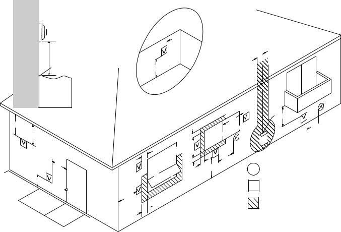
Clearances to access the appliance during servicing are 10 inches (254 mm) from the sides, 40 inches (1 m) from the front, and the area shown above the appliance in the picture.
clearance for |
maintenance |
Clearances to Combustibles
When determining where to install the appliance the clearances to combustibles shown in the figure must be followed. Also refer to the Safety Behaviors and Practices section.
Rinnai recommends 10” (254 mm) clearance from the top and on both sides for servicing.
0” (0 mm)
0” (0 mm)
2 in
(50 mm)
2 in
(50 mm)
40 in (1 m)
NOTICE |
The 40 inch (1 meter) clearance from the |
front of the appliance does not include |
|
|
flooring material or carpeting that is less |
|
|
|
than 1.2 inches (30 mm) in height. |
|
|
Checklist to Determine Installation Location
□The furnace is not exposed to corrosive compounds in the air.
□The furnace location complies with the clearances.
□The planned venting will not exceed the maximum length for the number of elbows used.
□The planned venting termination/air intake location meets the clearances.
□Indoor air is not being used for combustion.
□A standard 3 prong 120 VAC, 60 Hz properly grounded wall outlet.
□The installation must conform with local codes or,
in the absence of local codes, with the National Fuel Gas Code, ANSI Z223.1/NFPA 54, or the Natural Gas and Propane Installation Code, CSA B149.1. If installed in a manufactured home, the installation must conform with the Manufactured Home Construction and Safety Standard, Title 24 CFR, Part 3280 and/or CAN/SCA Z240 MH Series, Mobile Homes.
□Leave the entire manual with the consumer.
Rinnai Corporation EX17CT, EX22CT Manual |
9 |

Drilling Flue Hole
Ensure that there are no gas or water lines, or electrical circuits in the wall location where the flue hole is to be drilled. Drill the flue hole using a 3 1/8 inch (80 mm) drill. The center of the hole must be located exactly at the specified point.
See diagram. For weatherboard walls, drill through the center of the weatherboard from the outside first and then through the plasterboard. A template is provided.
For installation without using extension kits, the configuration of the flue manifold, air intake hose, and exhaust slide pipe should be as shown when installation is completed. The 60 degree arc shows where the flue manifold can be located.
|
|
|
|
|
|
|
|
R |
mm |
|
8 7/16" (214 mm) |
|
|
||||||
|
|
(R206 |
|||||||
|
|
|
|
|
|||||
Flue Hole |
|
8 9/16" |
|||||||
|
|
|
|
3 1/8" |
(80 mm) |
|
(217 mm) |
||
|
|
|
|
|
|
|
|||
|
|
|
|
|
|
|
|||
|
|
|
|
|
|
|
|||
|
|
|
|
||||||
|
|
|
|
|
|
|
|
||
|
|
||||||||
NOTICE |
Use a template (included) to |
||||||||
|
|
|
|
|
|
determine allowable location of the |
|||
|
|
|
|
|
|
||||
|
|
|
|
|
|
flue hole. |
|
|
|
|
|
|
|
|
|
|
|
|
|
Flue Manifold Installation
The flue manifold must exhaust to the outside. Do not exhaust into other rooms.
The flue manifold is not designed to be positioned under floors or below the heater.
The termination cannot be vertical.
This appliance can only be used with one of the five types of Rinnai flue kits. The flue kits and their dimensions are listed in the Specifications section.
Refer to the Flue Terminal Clearances section.
1.Disassemble the flue manifold The flue consists of 3 parts:
|
Inside Connection |
Terminal |
sleeve |
|
inside connection
outside terminal
Disassemble the flue manifold by first pulling out the inside connection. To remove the outer terminal pull and release the two internal ties and then pull out the outer terminal.
Sleeve
Clearance to combustibles for the sleeve and flanges is zero inches.
2.Adjust the sleeve length
Measure wall thickness through previously drilled 3 1/8 inch (80 mm) hole.
The end of the sleeve should protrude 3/16 - 3/8 inch (5-10 mm) from the outside wall.
The sleeve is threaded for adjustment. Adjust the sleeve length to wall thickness plus 3/16 - 3/8 inch (5-10 mm).
NOTE: Do not extend beyond the red line.
For other than the “S” type flue manifold, if a shorter length is necessary an extension can be removed. Cut the outer plastic laminate (with a utility knife or similar) and remove the extension. The metal should not be cut.
Remove extension if necessary
10 |
Rinnai Corporation EX17CT, EX22CT Manual |
Flue Manifold Installation
3.Attach the sleeve
Attach to the inside wall using 3 screws arranging the flange so that the marking “TOP” is at the top.
The flange is offset 2° to allow the condensate drain to the outside.
3 screws
sleeve should extend 3/16 - 3/8 in (5-10 mm)
4. |
Install the Terminal |
Terminal seal |
|
Check that the terminal seal is in place. For |
|
|
|
|
|
weatherboard walls, add the second seal next |
|
|
to the terminal seal to compensate for |
|
|
weather board angle. |
|
|
From the outside insert the terminal into the |
|
|
sleeve with the marking “TOP” at the top. |
|
|
The left hand side locking tie should be |
Terminal |
|
marked “LEFT”. |
|
|
|
|
|
|
Locking tie |
5. |
Lock the ties |
|
|
Pulling hard on the left and right hand ties, |
Locking ties |
|
clip the ties over the notches inside the |
Sleeve |
|
sleeve. You should be able to pull the ties 2 |
|
|
or 3 notches past the starting point. Cut the |
|
|
ties, leaving about 3/4 inch (20 mm) past the |
|
|
notch. Bend the ties back into the sleeve and |
|
|
parallel to the wall. |
|
6. Insert Inside Connection Assembly
Push the assembly into the terminal tube, ensuring that the seal is in place on the inner tube.
Attach the inside connection with 3 screws. The inner connection can still be turned to install the screws.
3 screws
Rinnai Corporation EX17CT, EX22CT Manual |
11 |

Extension Kit Installation
If necessary, extension kits are available to extend the exhaust line and air intake hose between the manifold and the appliance.
(1)The maximum vent length is 13 feet (4 m) with 2 bends. The bent pipe attached to the appliance does not count toward the max limit of 2 bends.
(2)Maximum vertical length allowed is 10 feet (3 m).
(3)If the extension is longer than 10 feet (3 m), the condensate may overflow the condensation pan. Therefore, extension exceeding this length should drain to the outside and sloped 3° downward.
(4)Do not allow any low points or sagging in the exhaust line. Otherwise, condensate may block the exhaust and affect combustion.
(5)Vent extensions installed in unconditioned air space must be insulated with high temperature insulation and must be accessible.
(6)Vent extensions must not be concealed per NFPA 54 and must be accessible allowing inspection and repair. Decorative covers are available from Rinnai.
These figures show the 2 possible ways that the extension exhaust line and air intake hose may be directed away from the appliance. All views are from behind the appliance. For your configuration, position the air intake hose as shown.
INCORRECT
Too many bends (limit is 2)
Air intake hose is above exhaust pipe
Exhaust Line
 Pipe
Pipe
Stopper A
Pipe Clamp
Air Intake Hose
Plastic Tie
Extension lines are through the side panel of the appliance.
It is not possible to position the extension lines through the other side panel of the appliance.
One elbow is shown. One additional elbow may be added.
Instructions (1)-(6) must be followed.
Exhaust Line
 Pipe Stopper A
 Pipe Clamp
 Air Intake Hose
Plastic Tie
Extension lines are through the top panel of the appliance above where the exhaust exits the appliance.
No elbows are shown. Two additional elbows may be added.
Instructions (1)-(6) must be followed.
12 |
Rinnai Corporation EX17CT, EX22CT Manual |
Extension Kit Installation
CAUTION |
Use the pipe stoppers, connectors, clamps, and screws according to these instructions in |
|
order to ensure no leakage of exhaust gases. |
|
|
|
|
Clearances |
exhaust pipe to combustibles |
1 inch (25.4 mm) |
|
|
|
|
|
|
exhaust pipe to non-combustibles |
zero |
|
|
|
|
|
Clamps |
Exhaust pipe |
||
|
|
||
Both the exhaust line and air intake hose are |
|
|
|
supported by clamps which are attached to the wall. |
|
|
|
A wall fixture can be used to offset the clamp from the |
|
|
|
wall. Use Screw B to attach the wall fixture to the |
|
|
|
wall. If the wall fixture is not used then use Screw A |
|
|
|
and the nut to attach the clamp to the wall. |
|
|
|
The air intake hose should always be underneath the |
|
|
|
exhaust line so that in case the air intake hose sags it |
|
|
|
will not come into contact with the exhaust line. |
|
|
|
|
|
Air intake hose |
|
Exhaust pipe
Air intake hose
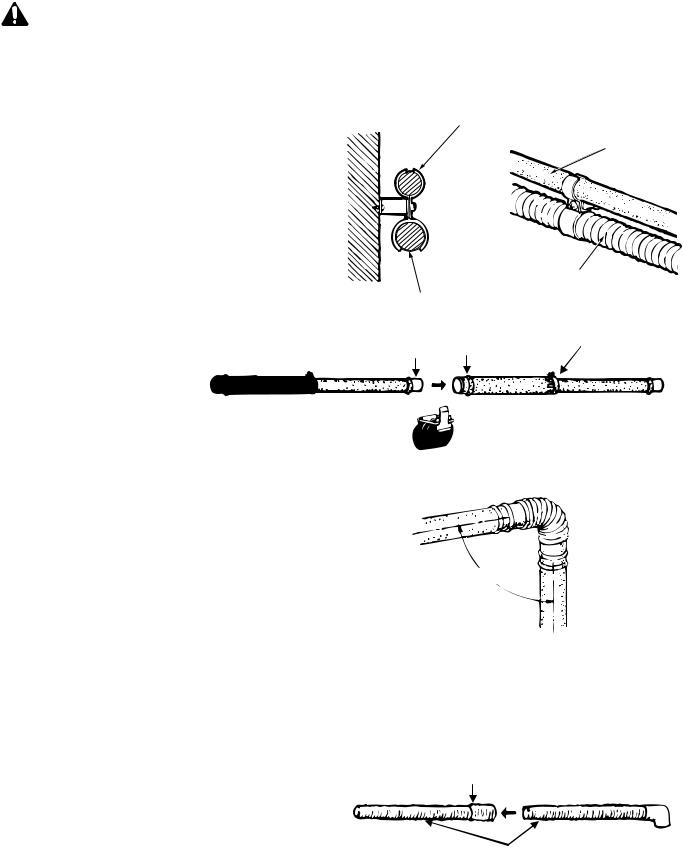
Installing the Exhaust Line
The exhaust line is connected between the bent pipe at the rear of the heater and the exhaust port on the flue manifold.
To connect exhaust pipes with other straight pipes or bends, fit the male end into the female end. Use pipe stopper A to clamp the connection.
Use pipe stopper B to fix the length on the adjustable exhaust pipes. Do not extend these pipes beyond the red line.
Do not cut the exhaust pipe. Use the adjustable pipes if necessary.
To bend the elbow, insert exhaust pipes into both ends for additional leverage. Bend to desired angle.
Do not straighten the bent pipe attached to the appliance.
Connecting the Air Intake Hose
The air intake hose is connected between the air connection at the rear of the heater and the air intake port on the flue manifold.
Push the air intake hose onto the flue manifold and secure with the plastic cable tie.
Join air intake hoses by screwing the hose joint half of its length into the air intake hose and then screwing another air intake hose into the hose joint.
NOTICE |
Do not cut the intake hose. Cutting |
|
the intake hose may result in noise. |
|
|
|
|
Male end |
Female end |
Pipe stopper B |
|


 Pipe stopper A
Adjust the
The lengths of the air intake hose and the exhaust pipe must be the same in order for the appliance to operate properly. The hose can be cut to the required length. Deburr all rough edges. Do not cut the hose attached to the appliance.
Support the air intake hose with pipe clamps.
Hose joint
Air intake hoses
Rinnai Corporation EX17CT, EX22CT Manual |
13 |
Extension Kit Installation
Extension Kits and Parts
EXHAUST PIPE (ADJUSTABLE) |
EXHAUST PIPE (NON ADJUSTABLE) |
AIR INTAKE HOSE |
BENT ELBOW |
LONG BENT ELBOW HOSE JOINT |
PIPE STOPPER A PIPE STOPPER B |
PIPE CLAMP |
WALL-FIXTURE |
|
NUT |
SCREW A |
SCREW B |
||||
|
|
|
|
|
|
|
|
|
|
Item |
|
Description |
|
FOT-201 |
FOT-219 |
FOT-220 |
FOT-221 |
FOT-158 |
FOT-190 |
|
|
|
|
|
|
|
|
|
|
1 |
Exhaust Pipe (adjustable) |
|
|
1 |
|
|
|
|
|
|
11.4-20.3 in (290-515 mm) |
|
|
|
|
|
|
|
|
TOP STOPPER |
|
|
|
|
|
|
|
||
1 |
Exhaust Pipe (adjustable) |
|
|
|
1 |
1 |
|
|
|
|
21.0-39.6 in (533-1005 mm) |
|
|
|
|
|
|
|
|
|
|
|
|
|
|
|
|
|
|
2 |
Exhaust Pipe - 40 in (1016 mm) |
|
|
|
|
1 |
|
|
|
|
|
|
|
|
|
|
|
|
|
3 |
Air Intake Hose - 29.5 in (750 mm); |
|
1 |
|
|
|
|
|
|
|
1.5 in (38 mm) inner dia. |
|
|
|
|
|
|
|
|
|
|
|
|
|
|
|
|
|
|
3 |
Air Intake Hose - 29.5 in (750 mm); |
|
1 |
1 |
|
|
|
|
|
|
2.0 in (50 mm) inner dia. |
|
|
|
|
|
|
|
|
|
|
|
|
|
|
|
|
|
|
3 |
Air Intake Hose - 49.2 in (1.25 m) |
|
|
|
1 |
|
|
|
|
|
2.0 in (50 mm) inner dia. |
|
|
|
|
|
|
|
|
|
|
|
|
|
|
|
|
|
|
3 |
Air Intake Hose - 90.6 in (2.3 m) |
|
|
|
|
1 |
|
|
|
|
2.0 in (50 mm) inner dia. |
|
|
|
|
|
|
|
|
|
|
|
|
|
|
|
|
|
|
4 |
|
Bent Elbow |
|
|
|
|
|
1 |
|
|
|
|
|
|
|
|
|
|
|
5 |
Long Bent Elbow |
|
1 |
|
|
|
|
1 |
|
|
|
|
|
|
|
|
|
|
|
6 |
Hose Joint - 1.5 in (38 mm) inner dia. |
|
1 |
|
|
|
|
|
|
|
|
|
|
|
|
|
|
|
|
6 |
Hose Joint - 2.0 in (50 mm) inner dia. |
|
1 |
1 |
1 |
1 |
|
|
|
|
|
|
|
|
|
|
|
|
|
7 |
|
Pipe Stopper A |
|
1 |
1 |
1 |
2 |
1 |
1 |
|
|
|
|
|
|
|
|
|
|
8 |
|
Pipe Stopper B |
|
|
1 |
1 |
1 |
|
|
|
|
|
|
|
|
|
|
|
|
9 |
|
Pipe Clamp |
|
|
2 sets |
3 sets |
4 sets |
|
|
|
|
|
|
|
|
|
|
|
|
10 |
|
Wall Fixture |
|
|
2 |
3 |
4 |
|
|
|
|
|
|
|
|
|
|
|
|
11 |
|
Nut |
|
|
2 |
3 |
4 |
|
|
|
|
|
|
|
|
|
|
|
|
12 |
|
Screw A |
|
|
2 |
3 |
4 |
|
|
|
|
|
|
|
|
|
|
|
|
13 |
|
Screw B |
|
|
4 |
6 |
8 |
|
|
|
|
|
|
|
|
|
|
|
|
14 |
Rinnai Corporation EX17CT, EX22CT Manual |

Connecting the Appliance
1. Attach the air inlet hose to the flue manifold on |
a |
|
|
either inlet position “a” or “b”. |
|
The plastic tie should be tight over the sleeve. |
|
The unused inlet is plugged with the rubber cap |
b |
supplied on the manifold. |
|
2.Connect the flue elbow to the manifold while moving the appliance into position.
Flue Manifold
3.Fit the pipe stopper over the connection between the flue elbow and the manifold. Engage the hook and rotate it until it snaps against the body of the clamp.
Pipe stopper
|
Hook |
|
Manifold |
Elbow |
Pipe stopper |
4.Slide the insulation sleeve up to the flue manifold and slip the securing clip over the sleeve as shown.
5.Install the bracket on the rear of the top spacer by tightening 2 screws.
Spacer bracket
Top Spacer
6.Install the wall bracket with two screws. Install the top spacer by clipping the spacer into the wall brackets and attaching it to the heater with 2 screws.
Top Spacer
Wall bracket
Top Spacer
Spacer
Bracket
Wall
Bracket
Rinnai Corporation EX17CT, EX22CT Manual |
15 |
Checklist for Venting
□Verify proper clearances around the vents and air intakes.
□Ensure you have used the correct venting
products for the model installed and that you have completely followed the venting manufacturer’s installation instructions and these installation instructions.
□Verify that the vent system does not exceed the maximum length for the number of elbows used.
Gas Connection
 WARNING
When connecting the gas valve or other gas components in the gas line, use a backup wrench to ensure the connection is gas tight.
The gas supply line shall be gas tight, sized and so installed as to provide a supply of a gas sufficient to meet the maximum demand of the furnace without loss of pressure.
A shut off valve and appliance connector valve should be installed in the upstream of the gas line to permit servicing.
Flexible pipe and any appliance connector valve used for gas piping shall be types approved by nationally recognized agencies.
Any compound used on the threaded joint of the gas piping shall be a type which resists the action of liquefied petroleum gas (propane / LPG).
After completion of gas pipe connections all joints including the furnace must be checked for gas tightness by means of leak detector solution, soap and water, or an equivalent nonflammable solution, as applicable. (Since some leak test solutions, including soap and water, may cause corrosion or stress cracking, the piping shall be rinsed with water after testing, unless it has been determined that the leak test solution is non-corrosive.)
Check the gas supply pressure immediately upstream at a location provided by the gas company. Supplied gas pressure must be within the limits shown in the Specifications section.
Refer to an approved pipe sizing chart if in doubt about the size of the gas line.
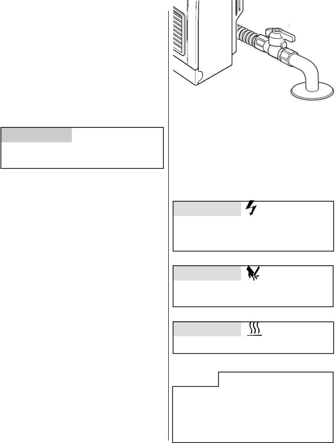
Install manual gas cut-off valve so that it can be accessed for easy operation. Do not conceal manual cut-off valve behind back spacer.
Manual gas shut-off valve
Adjust Gas Pressure Settings
Complete these instructions for altitude and vent length. (Default altitude: 0ft - 2,000ft. Default vent length: 0 - 7ft+1 elbow )
For high altitude installations in Canada, the conversion shall be carried out by a manufacturer’s authorized representative, in accordance with the requirements of the manufacturer, provincial or territorial authorities having jurisdiction and in accordance with the requirements of CAN/CGA-B149.1 or CAN/CGA-B149 installation codes.
 CAUTION
Do not touch any other areas on the PC board besides the “SW” switches while power is supplied to the appliance. Parts of the PC board are supplied with 120 volts AC.
 CAUTION
Do not insert hands or objects into the circulation fans while they are running. Injury or mechanical malfunction may occur.
 CAUTION
Do not touch the areas at or near the exhaust. This area becomes very hot and could cause burns.
NOTICE
The regulator has been factory pre-set. If the pressure is incorrect, check the supply pressure first, before making any adjustments to the appliance. Also, if the low control pressure cannot be obtained, adjust the adjustment screw on the proportional valve to roughly set pressure and then recheck both the low and high fire pressures.
16 |
Rinnai Corporation EX17CT, EX22CT Manual |

Adjust Gas Pressure Settings
1.Turn off the gas and the power supply.
2.Remove the 5 screws that hold the louver assembly and front panel. Lift the panel straight up and then remove it.
3.Remove two pressure point screws (1/8 NPT tap) with 3/16 Allen wrench and attach the manometer to both pressure points. Both pressure points must be used in order to measure the differential pressure. Ensure that the manometer is properly calibrated.
4.Turn on the gas and power supply to the appliance. (Press the “Set back” button after turning on the power supply.) With the unit in the off position, press the test switch at the top of PC board until it beeps.
5.Select the correct code for gas type and altitude using ▲ and ▼ buttons. Refer to the table below.
6.Press the test switch twice to record the gas type code into memory. .
7.Press the ON/OFF button to operate the appliance.
8.Press the test switch twice. The LED will display “PL” indicating low fire mode.
9.Compare the pressure reading on the manometer to the desired manifold test pressure (low) for your gas type and altitude. If necessary adjust the low fire pressure using the ▲ and ▼ buttons.
10.Press the test switch. The LED will display “PH” indicating high fire mode.
Pressure
Point
Test Switch
PC
Board
Nozzle
Manifold
Pressure
Point
|
|
Natural Gas |
|
|
Propane Gas |
|
|||
|
|
|
|
|
|
|
|
|
|
Code |
A1 / A5 |
A2 / A6 |
A3 / A7 |
A4 /A8 |
L1 / L5 |
L2 / L6 |
L3 / L7 |
L4 / L8 |
|
|
|
|
|
|
|
|
|
|
|
|
0-2000 ft |
2001-5200 ft |
5201-7700 ft |
7701-10200 ft |
0-2000 ft |
2001-5200 ft |
5201-7700 ft |
7701-10200 ft |
|
Altitude |
0-610 m |
611-1585 m |
1586-2347 m |
2348-3109 m |
0-610 m |
611-1585 m |
1586-2347 m |
2348-3109 m |
|
|
|||||||||
|
|
|
|
|
|
|
|
|
|
EX17CT |
|
|
|
|
|
|
|
|
|
|
|
|
|
|
|
|
|
|
|
Manifold test |
0.44 in |
0.48 in |
0.54 in |
0.60 in |
0.68 in |
0.74 in |
0.82 in |
0.92 in |
|
pressure - |
|||||||||
(11 mm) |
(12 mm) |
(14 mm) |
(15 mm) |
(17 mm) |
(19 mm) |
(21 mm) |
(23 mm) |
||
W.C. Low |
|||||||||
|
|
|
|
|
|
|
|
||
|
|
|
|
|
|
|
|
|
|
Manifold test |
1.6 in |
1.4 in |
1.2 in |
1.1 in |
2.7 in |
2.4 in |
2.2 in |
2.0 in |
|
pressure - |
|||||||||
(40 mm) |
(35 mm) |
(32 mm) |
(29 mm) |
(69 mm) |
(61 mm) |
(55 mm) |
(50 mm) |
||
W.C. High |
|||||||||
|
|
|
|
|
|
|
|
||
|
|
|
|
|
|
|
|
|
|
EX22CT |
|
|
|
|
|
|
|
|
|
|
|
|
|
|
|
|
|
|
|
Manifold test |
0.44 in |
0.48 in |
0.54 in |
0.60 in |
0.68 in |
0.74 in |
0.82 in |
0.92 in |
|
pressure - |
|||||||||
(11 mm) |
(12 mm) |
(14 mm) |
(15 mm) |
(17 mm) |
(19 mm) |
(21 mm) |
(23 mm) |
||
W.C. Low |
|||||||||
|
|
|
|
|
|
|
|
||
|
|
|
|
|
|
|
|
|
|
Manifold test |
2.6 in |
2.2 in |
2.0 in |
1.8 in |
4.0 in |
3.5 in |
3.1 in |
2.9 in |
|
pressure - |
|||||||||
(65 mm) |
(57 mm) |
(52 mm) |
(47 mm) |
(101 mm) |
(89 mm) |
(80 mm) |
(72 mm) |
||
W.C. High |
|||||||||
|
|
|
|
|
|
|
|
||
|
|
|
|
|
|
|
|
|
|
Rinnai Corporation EX17CT, EX22CT Manual |
17 |
Adjust Gas Pressure Settings
11.Compare the pressure reading on the manometer to the desired manifold test pressure (high) for your gas type and altitude. If necessary adjust the high fire pressure using the ▲ and ▼ buttons.
12.Press the ON/OFF button again. The LED display turns blank and the appliance returns to the normal OFF mode.
13.Remove manometer and install Allen head screws. Operate the unit and
check the normal operating sequencevisually inspect the flame
check for gas leaks at the test points
Normal Operating Sequence
When you press the ON/OFF button, the LED display will illuminate, the combustion fan will begin to run, and the spark will ignite the main burner.
This heater has an automatic ignition system. When the main burner has lit, the combustion lamp will glow red, and the spark will stop.
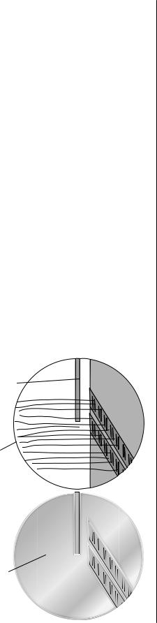
Visual Inspection of Flame
Check that the burner flames are operating normally. The flame can be seen through the circular window through the louvers.
When operating normally the burner flame should appear as long, clear, blue, stable, streaks. Yellow flames or an orange color is abnormal and maintenance is required.
NORMAL
Flame Rod
Long, clear, blue, stable flames
ABNORMAL
Flame Rod 
Yellow flames or orange color
Final Assembly
1.Install the front panel and bottom cover.
2.If doing a gas type conversion, place the new conversion plate (label) on the front cover.
Checklist for Gas and Electricity
□A manual gas control valve is placed in the gas line to the heater.
□Check the gas lines and connections for leaks.
□Confirm that the gas inlet pressure is within limits.
□Confirm that the heater is rated for the gas type supplied.
□Confirm that the electricity is supplied from 120 VAC, 60 Hz power source and is in a properly grounded circuit.
□Confirm that an extension cord or an adapter plug has NOT been used with the heater.
18 |
Rinnai Corporation EX17CT, EX22CT Manual |

Final Checklist
□The heater is not subject to corrosive compounds in the air.
□Clearances from the heater unit are met.
□Clearances from the vent termination are met.
□Ensure you have used the correct venting
products for the model installed and that you have completely followed the venting manufacturer’s installation instructions and these installation instructions.
□Verify that the vent system does not exceed the maximum length for the number of elbows used.
□A manual gas control valve has been placed in the gas line to the heater.
□Check the gas lines and connections for leaks.
□Confirm that the gas inlet pressure is within limits.
□Confirm that the heater is rated for the gas type supplied.
□Confirm that the electricity is supplied from a 120
VAC, 60 Hz power source, is in a properly grounded circuit, and turned on.
□Verify the system is functioning correctly by
connecting your manometer to the gas pressure test port on the water heater. Operate all gas appliances in the home or facility at high fire. The inlet gas pressure at the heater must not drop below that listed on the rating plate.
□Install the front panel.
□Explain to the customer the importance of not blocking the vent termination.
□Explain to the customer the operation of the
heater, safety guidelines, maintenance, and warranty.
□The installation must conform with local codes or,
in the absence of local codes, with the National Fuel Gas Code, ANSI Z223.1/NFPA 54, or the Natural Gas and Propane Installation Code, CSA B149.1. If installed in a manufactured home, the installation must conform with the Manufactured Home Construction and Safety Standard, Title 24 CFR, Part 3280 and/or CAN/SCA Z240 MH Series, Mobile Homes.
□Leave the entire manual with the consumer.
Rinnai Corporation EX17CT, EX22CT Manual |
19 |
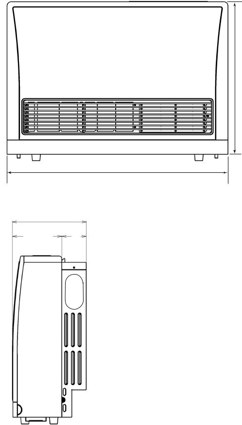
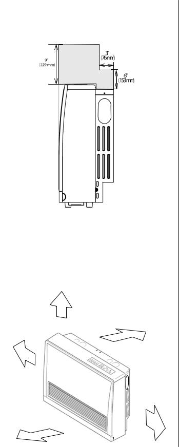
Dimensions
inches (mm)
10.1 in
257mm
6.8in
172 mm
22.9 in
(582 mm)
29.9 in
(760 mm)
3.3 in
85 mm
NOTICE |
A full size template is provided on the |
|
cardboard packaging. |
|
|
|
DO NOT DISCARD until installation is |
|
completed. |
|
|
20 |
Rinnai Corporation EX17CT, EX22CT Manual |
Specifications
Safety Features
Overheat: The appliance will automatically shut down when the appliance exceeds a predetermined temperature.
Flame Failure: The appliance will automatically shut down if the burner flame is extinguished.
Power Failure: The appliance will shut off the gas if it loses electrical power.
Power Surge Fuse: A glass fuse on the PC board protects against overcurrent. If the fuse blows then all indicator lamps will be off.
Spark Detector: The appliance automatically shuts down if there is an abnormal spark at ignition.
Fusible Link: In case the overheat feature does not prevent an overheat then the fusible link could break, shutting off the appliance.
Appliance Specifications
|
EX17CT |
EX22CT |
|||
|
|
|
|
||
|
Approved for manufactured home (USA only) or mobile home or residential installation |
||||
|
convertible for use with natural gas and liquefied petroleum gases (propane / LPG) |
||||
Application |
when provision is made for the simple conversion from one gas to the other. |
||||
|
Approved for commercial setting. |
|
|
||
|
Approved for installation at altitudes up to 10,200 feet (3109 m). |
|
|||
|
|
|
|
||
|
Natural Gas |
Propane Gas |
|||
|
|
|
|||
Min. Supply Gas Pressure |
3.5 in(89 mm) W.C. |
8.0 in(203 mm) W.C. |
|||
|
|
|
|||
Max. Supply Gas Pressure |
10.5 in(267 mm) W.C. |
13.0 in(330 mm) W.C. |
|||
|
|
|
|||
BTU/hour input |
Low 8200 High 16700 |
Low 8200 High 21500 |
Low 8200 High 20700 |
||
|
|
|
|
||
BTU/hour output |
Low 6560 High 13360 |
Low 6560 High 17200 |
Low 6560 High 16560 |
||
|
|
|
|
||
|
|
|
|||
General Description |
Forced combustion, forced convection, flued gas furnace |
|
|||
|
|
|
|
|
|
Operation |
Push button electronic |
|
|
|
|
|
|
|
|
|
|
Gas Connection |
1/2 in male NPT |
|
|
|
|
|
|
|
|
|
|
Gas Control |
Electronic |
|
|
|
|
|
|
|
|
||
Burners |
Stainless steel Bunsen burner |
|
|
||
|
|
|
|||
Temperature Control |
Electronic thermostat, (Low, 60-80ºF in 2ºF increments, High) |
|
|||
|
|
|
|
||
Temperature Range |
Low, 60 - 80°F (in 2°F increments), High |
|
|
||
|
|
|
|
|
|
Ignition System |
Electronic spark ignition |
|
|
|
|
|
|
||||
Flue System |
The flue must be terminated to atmosphere with only flue components listed with the |
||||
appliance’s certification. Warranty will be voided if non listed components are installed. |
|||||
|
|||||
|
|
|
|
||
Humidifier Tray |
Capacity - 2.1 pints (1000 cc) |
|
|
||
|
|
|
|||
Electrical Connection |
AC 120V, 60 Hz, 46 watts |
AC 120V, 60 Hz, 56 watts |
|||
|
|
|
|
|
|
Standby Power |
0.5 watt |
|
|
|
|
|
|
|
|
|
|
Weight |
57 lbs (26 kg) |
|
|
|
|
|
|
|
|
|
|
Noise Level |
33-38 dB |
|
33-42 dB |
|
|
|
|
|
|
|
|
AFUE Rating |
Natural Gas: 81% |
Propane: 82% |
Natural Gas: 80% |
Propane: 82% |
|
|
|
|
|
|
|
Rinnai is continually updating and improving products. Therefore, specifications are subject to change without prior notice.
The efficiency rating of this appliance is a product thermal efficiency rating determined under continuous operating conditions and was determined independently of any installed system.
Rinnai Corporation EX17CT, EX22CT Manual |
21 |
Direct Vent Furnace Operation Instructions
EX17CT .............. (RHFE-434FTA2)
EX22CT .............. (RHFE-559FTA2)
Important Facts about your Direct Vent Furnace
Thank you for purchasing a Rinnai Direct Vent Furnace. For proper operation and safety, it is important to follow the instructions and adhere to all safety precautions.
Read all of the instructions and the warranty thoroughly before operating this heater. Keep this manual in a safe place.
NOTICE: Rinnai sometimes shares customer contact information with businesses that we believe provide products or services that may be useful to you. By providing this information, you agree that we can share your contact information for this purpose. If you prefer not to have your information shared with these businesses, please contact customer service and ask not to have your information shared. We will however, continue to contact you with information relevant to the product(s) you registered and/or you account with us.

 WARNING If the information in these instructions is not followed exactly, a fire or explosion may result causing property damage, personal injury, or death.
—Do not store or use gasoline or other flammable vapors and liquids in the vicinity of this or any other appliance.
—WHAT TO DO IF YOU SMELL GAS
Do not try to light any appliance.
Do not touch any electrical switch; do not use any phone in your building.
Immediately call your gas supplier from a neighbor’s phone. Follow the gas supplier’s instructions.
If you cannot reach your gas supplier, call the fire department.
—Installation and service must be performed by a licensed professional.
22 |
Rinnai Corporation EX17CT, EX22CT Manual |
Safe Operation
FOR YOUR SAFETY READ BEFORE OPERATING
|
WARNING |
If you do not follow these instructions exactly, a fire or explosion |
|
||
|
|
may result causing property damage, personal injury or loss of life. |
|
||
|
|
||||
|
|
|
|
||
A.This appliance does not have a pilot. It is equipped |
department. |
||||
with an ignition device which automatically lights |
C.Use only your hand to push in or turn the gas control |
||||
the burner. Do not try to light the burner by hand. |
|||||
knob. Never use tools. If the knob will not push in |
|||||
|
|
|
|||
B.BEFORE OPERATING smell all around the |
or turn by hand, do not try to repair it, call a |
||||
appliance area for gas. Be sure to smell next to |
qualified service technician. Force or attempted |
||||
the floor because some gas is heavier than air and |
repair may result in a fire or explosion. |
||||
will settle on the floor. |
|
D.Do not use this appliance if any part has been under |
|||
|
|
|
|||
WHAT TO DO IF YOU SMELL GAS |
water. Immediately call a qualified service |
||||
Do not try to light any appliance. |
technician to inspect the appliance and to replace |
||||
Do not touch any electric switch; do not use any |
any part of the control system and any gas control |
||||
phone in your building. |
|
which has been under water. |
|||
Immediately call your gas supplier from a neighbor’s phone. Follow the gas supplier’s instructions.
If you cannot reach your gas supplier, call the fire
OPERATING INSTRUCTIONS
STOP! Read the safety information above. |
5. |
Turn the manual gas valve counterclockwise |
|
1. Set the thermostat to lowest setting. |
|
|
to the full ON position. |
|
|
|
|
2. Turn off all electric power to the appliance using |
6. |
Turn on all electric power to the appliance using the |
|
|
ON/OFF button. |
||
the ON/OFF button on the control panel. Locate |
|
||
|
|
||
the manual gas valve on the back side of the |
7. |
Set the thermostat to desired setting. |
|
heater. |
|
8. |
Burner is lit when indicator lamp “ON turns red. |
|
|
||
3. Turn the manual valve clockwise |
to the full |
9. |
“ON” indicator and fault code 11, flash when burner |
OFF position. |
|
||
|
|
fails to ignite. |
|
|
|
|
|
Manual Valve |
|
10. If the appliance will not operate, follow the |
|
|
|
||
CLOSE |
OPEN |
|
instructions “To Turn Off Gas To Appliance” and |
|
|
|
call your service technician or gas supplier. See |
|
|
|
manual for additional information. |
4. Wait five (5) minutes to clear out any gas. Then smell for gas, including near the floor. If you smell gas, STOP! Follow “B” in the safety information above. If you don’t smell gas, go to the next step.
|
TO TURN OFF GAS TO APPLIANCE |
|
|
||
1.Set the thermostat to lowest setting. |
|
NOTE: The fan will continue to operate until the |
|
||
2.Turn off all electric power to the appliance using the |
appliance is cool. Do not turn the appliance off |
||||
by unplugging it from the wall. Keep burner |
|
||||
ON/OFF button on the control panel. |
|
|
|||
|
and control compartment clean. |
|
|||
|
|
|
|
||
3.Locate the manual gas valve on the side of the unit. |
|
|
|
||
Turn the manual valve clockwise |
to the full |
|
|
|
|
OFF position. |
|
|
|
|
|
|
Rinnai Corporation EX17CT, EX22CT Manual |
23 |
|||
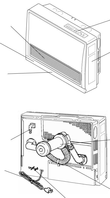
Getting to Know Your Appliance
WARM AIR OUTLET
HUMIDIFIER
REMOVE BOTTOM
COVER AND PULL OUT
TO REFILL
BOTTOM COVER
HOLD BOTH SIDES
AND PULL TOWARD
YOU
GAS CONNECTION
1/2” MALE NPT
POWER CORD
PLUG 120V AC, 60 Hz
CONTROL PANEL
RATING PLATE
MODEL NUMBER,
SERIAL NUMBER,
GAS TYPE, ETC.
ENGLISH IS ON THE
RIGHT; FRENCH IS
ON THE LEFT
 AIR FILTER
VENT TERMINAL
COMBUSTION AIR/
EXHAUST
 EXHAUST PIPE
COMBUSTION AIR
INTAKE HOSE
ROOM TEMPERATURE
SENSOR/THERMISTOR
24 |
Rinnai Corporation EX17CT, EX22CT Manual |

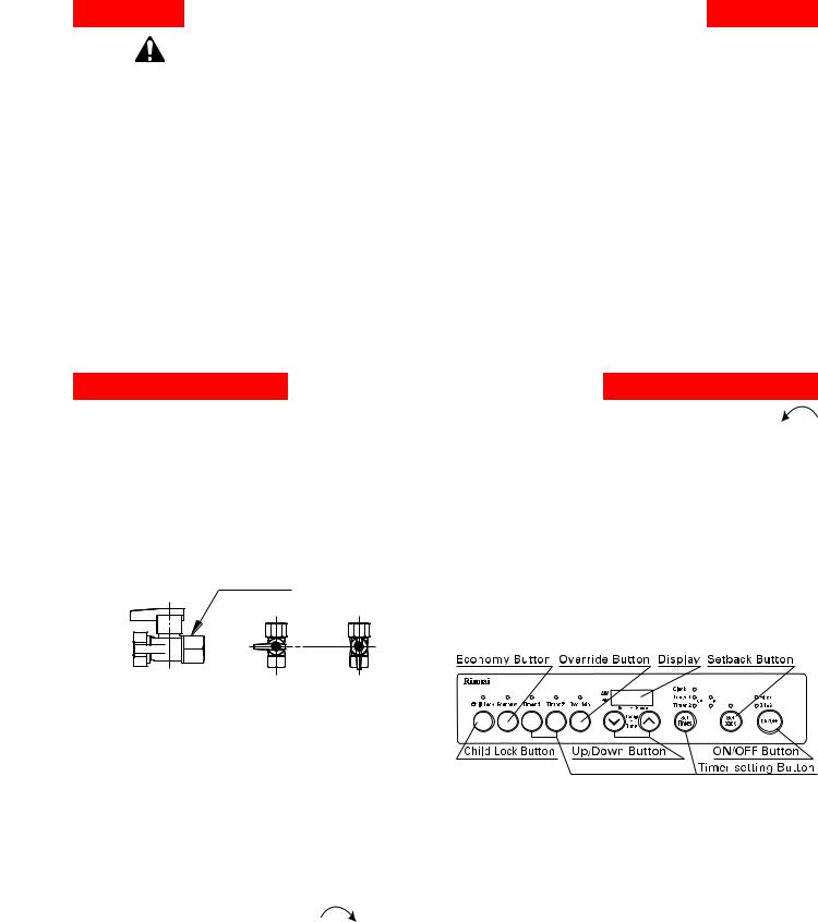
Control Panel
Sensible Temperature Control
The sensible temperature control feature allows comfortable heating which matches the conditions in the room.
Based on the information collected by the room temperature thermistor when the heating starts, the heating capacity is automatically adjusted to achieve a
comfortable heating effect and to reach the temperature setting quickly.
Occasionally, the room temperature may briefly exceed the temperature setting due to the layout of the room or heating area.
Display
After the heater is turned on and begins operating, the display will dim. The display will turn off when the heater is turned off. While programming the timers the display will turn off several seconds after a button is last pushed.
Fahrenheit or Celsius
1.The heater must be turned off.
2.Press the Timer 1 and Timer 2 button at the same time for about 5 seconds. The display will show “ºC” or “ºF”.
3.Use the arrow keys to select the temperature scale.
4.Press the ON/OFF button.
ON / OFF
Press the ON/OFF button to operate the heater. The ON indicator will glow green. Once the burner ignites the ON indicator will glow red. When the heater warms up, the fan will automatically start.
To turn the heater off, press the ON/OFF button. The ON indicator light will go out. The fan will continue to operate for several minutes after the burner has gone out in order to cool the heater. Do not unplug the heater while the fan is running.
Child Lock
The Child Lock will help to prevent accidental operation of the appliance and to prevent children from operating the appliance.
To activate Child Lock, press the Child Lock button. The indicator will light and a beep will sound.
To deactivate Child Lock, press the Child Lock button and hold for about 2 seconds. The indicator light will go out and a beep will sound.
The lock can be activated when the heater is ON or OFF.
If activated while the heater is ON, all controls other than the OFF switch will be locked.
If activated while the heater is OFF, then all controls will be locked.
If the heater is turned off while the Child Lock is activated, it cannot be turned on again until the lock is deactivated.
Deactivating the lock releases the control buttons.
Rinnai Corporation EX17CT, EX22CT Manual |
25 |

Remote Thermostat Mode (Optional Accessory)
A remote thermostat can be installed for the furnace with the Remote Thermostat Installation Kit (Part # 204000045). Once installed, the furnace must be placed in Remote Thermostat mode by following the steps below:
1.Ensure the furnace is plugged in but is turned OFF.
2.Ensure the Set back feature is turned OFF.
3.Press and hold the Economy + Up + Program buttons for 2.5 seconds and then release (00 appears in the display).
4.Press the UP button (01 appears in the display).
5.Press the ON/OFF button; the display will go blank. The furnace is now in Remote Thermostat mode.
ATTENTION Do not unplug the furnace within two hours of entering Remote Thermostat mode. This will cause the furnace to revert back to Control Panel mode (default).
Note: To return the furnace back to Control Panel mode, repeat steps 1-3. At step 4, press the UP button until 02 appears in the display. Next, press the ON/OFF button; the display will go blank. The furnace is now in Control Panel mode.
00 -
01 -
02 -
Default Factory Setting
Remote Thermostat Mode
Control Panel Mode
|
|
|
|
|
|
|
|
|
|
|
|
|
|
|
|
|
|
|
|
|
|
|
|
|
|
|
|
|
|
|
|
|
|
|
|
|
|
|
|
|
|
|
|
|
|
|
|
|
ECONOMY |
|
UP |
|
SET TIMES |
|
|
|
|
|
|
|
|
|
|
 ATTENTION
DO NOT place heater back into “00” default factory setting without wall thermostat connection components. Failure to do so may cause the unit not to function properly.
The following buttons/indicators on the control panel will remain functional in either mode:
ON/OFF Button
FILTER Indicator
ON Indicator
DISPLAY (The DISPLAY will be blank except in the event of an error code. All error codes will show on the DISPLAY in either mode. Error codes will not show on the remote thermostat even when in remote thermostat mode.)
ATTENTION |
The remote thermostat will NOT control the heaters ability to power on or power down. |
|
This must still be done by using the ON/OFF button of the heater. |
|
|
26 |
Rinnai Corporation EX17CT, EX22CT Manual |
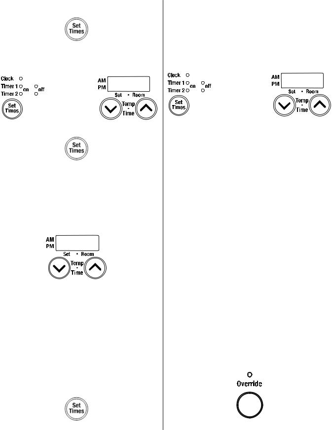
Setting the Clock
1.Press the “Set Times” button.
2.The light next to “Clock” should be lit. Press the up and down arrows to set the time. Holding down either of the arrow keys will change the time more quickly.
3.Press the “Set Times” button until none of the time options are lit up.
Operating the Furnace Manually
1.Turn the heater on by pressing the “ON/OFF” button.
2.Press the up or down arrows to set the temperature. The left side of the display shows the temperature setting. The right side of the display shows the room temperature.
Setting and Operating the Timers
Confirm the clock is correct.
NOTE: The clock will have to be reset in case of a power failure. However the timers will retain their settings.
The heater will start before the programmed starting time in order to heat the room by the programmed starting time.
The timers can be set while the heater is on or off. To operate the timer, the heater must be on.
Setting the timers:
1. Press the “Set Times” button twice to set Timer 1.
2.The light next to “Timer 1 on” should be lit. Press the up or down arrows to set the start time. Holding down either of the arrow keys will change the time more quickly.
3.Press the “Set Times” button again so that the Timer 1 off position is lit. Press the up or down arrows to set the end time. Holding down either of the arrow keys will change the time more quickly.
4.Press the “Set Times” button again to set the times for Timer 2. Follow the same steps above to set the start and end times.
5.Press the “Set Times” button until none of the time options are lit up.
Operating the timers:
To operate the heater using a Timer, press ON/OFF button and the appropriate Timer button. The heater will operate from the start to end times you have entered for that Timer. It will operate at the temperature setting that has been set for the heater. The timer can be set while the heater is operating.
Override Function
This function is used only when the heater is in Timer operation.
It allows you to “override” the reset timer setting until the beginning of the next Timer period.
For example, if the heater is ON, pressing the “Override” button will turn the heater OFF until the next period. If the heater is OFF, pressing the “Override” button will turn the heater ON, and allow you to select a temperature setting, until the next period. The heater will remain on until the next timer period or until the Override function is turned off.
When in override function, pressing the “Override” button will return the heater to the operation of the current timer period.
Rinnai Corporation EX17CT, EX22CT Manual |
27 |
 Loading...